


Installation
Instructions
EasyLAN Wireless
Interface Kit
(for EasyCoder® PF2i,
PF4i, PF4i Compact
Industrial, PM4i, PX4i,
and PX6i Printers)

Intermec Technologies Corporation
Worldwide Headquarters
6001 36th Ave. W.
Everett, WA 98203
U.S.A.
www.intermec.com
e information contained herein is provided solely for the purpose of allowing
customers to operate and service Intermec-manufactured equipment and is
not to be released, reproduced, or used for any other purpose without written
permission of Intermec Technologies Corporation.
Information and specifications contained in this document are subject to
change without prior notice and do not represent a commitment on the part of
Intermec Technologies Corporation.
© 2004-2007 by Intermec Technologies Corporation. All rights reserved.
e word Intermec, the Intermec logo, Norand, ArciTech, Beverage Routebook,
CrossBar, dcBrowser, Duratherm, EasyADC, EasyCoder, EasySet, Fingerprint,
INCA (under license), i-gistics, Intellitag, Intellitag Gen2, JANUS, LabelShop,
MobileLAN, Picolink, Ready-to-Work, RoutePower, Sabre, ScanPlus, ShopScan,
Smart Mobile Computing, TE 2000, Trakker Antares, and Vista Powered
are either trademarks or registered trademarks of Intermec Technologies
Corporation.
ere are U.S. and foreign patents as well as U.S. and foreign patents pending.
Microsoft, Windows, and the Windows logo are registered trademarks of
Microsoft Corporation in the United States and/or other countries.
Torx is a registered trademark of Camcar Division of Textron Inc.
is product includes software developed by the OpenSSL Project for use in the
OpenSSL Toolkit (http://www.openssl.org/).
is product includes cryptographic software written by Eric Young (eay@
cryptsoft.com).

Document Change Record
is page records changes to this document. e document was
originally released as version -00.
Version Date Description of Change
-03 11/2006 Added WPA wireless security features, and descriptions of the
ROAM and AUTH parameters.
-04 08/2007 Removed transceiver module information and put this in a
separate document (P/N 933-134-001).
EasyLAN Wireless Interface Kit Installation Instructions iii

iv EasyLAN Wireless Interface Kit Installation Instructions

Contents
Before You Begin ........................................................................... ix
Safety Information .......................................................... ix
Global Services and Support ............................................ x
Who Should Read is Manual ......................................xi
Related Documents ........................................................ xi
Introduction
1
2
About ese Instructions ...............................................................2
Printer Firmware ............................................................................ 2
Installation Kit ...............................................................................2
Physical Installation
Step-by-Step Instructions ...............................................................4
EasyCoder PF2/4i Printers ...............................................4
EasyCoder PM4i Printers ................................................8
EasyCoder PX4/6i Printers ............................................ 11
Contents
Warranty Information ....................................... x
Web Support ..................................................... x
Telephone Support ............................................ x
Setup (General)
3
Setting up Network Parameters .................................................... 16
Establishing Serial Communications ............................................ 16
Setup with CompactFlash (Fingerprint only) ............................... 17
User and Password .......................................................................18
Setup in Fingerprint
4
EasyLAN Wireless Interface Kit Installation Instructions v
Setting Up Wireless Communications .......................................... 20
General .......................................................................... 20
Display Current User ......................................20
Changing User ................................................ 21
Changing Passwords ........................................ 22
Active ..............................................................22
SSID (Network Name) .................................................. 24
WEP ..............................................................................24

Contents
802.11 Authentication ................................................... 25
WPA ..............................................................................26
Roaming Bias ................................................................27
802.1x ...........................................................................27
Supported EAP Types ...................................... 27
802.1x Settings ................................................ 28
Using Certificates ............................................ 29
Examples .........................................................30
Reading Other Wireless Connection Variables .............................31
Active Channel .............................................................. 31
Access Point Information ...............................................32
Signal Strength ..............................................................32
Speed ............................................................................. 32
Region (a.k.a. Regulatory Domain) ...............................32
Reading Wireless Connection Setup .............................................33
Setting Up Network Parameters ................................................... 34
New Line ...................................................................... 34
IP Selection Method ......................................................34
IP Address .....................................................................35
Subnet Mask ..................................................................35
Default Router ...............................................................35
Name Server .................................................................. 35
Finishing the Setup ...................................................................... 35
Setup in IPL
5
vi EasyLAN Wireless Interface Kit Installation Instructions
Setting Up Wireless Communications .......................................... 38
General .......................................................................... 38
Display Current User ......................................38
Changing User ................................................ 38
Changing Passwords ........................................ 39
Active ..............................................................39
SSID (Network Name) .................................................. 40
WEP ..............................................................................40
802.11 Authentication ................................................... 41
WPA ..............................................................................42
Roaming Bias ................................................................43
802.1x ...........................................................................43
Supported EAP Types ...................................... 43
802.1x Settings ................................................ 44
Using Certificates ............................................ 45

Examples .........................................................46
Reading Other Wireless Connection Variables .............................47
Active Channel .............................................................. 48
Access Point Information ...............................................48
Signal Strength ..............................................................48
Speed ............................................................................. 48
Region (a.k.a. Regulatory Domain) ...............................49
Finishing the Wireless Setup ........................................................49
Setting Up Network Parameters ................................................... 50
Setting the IP Selection Method ....................................50
Reading the IP Address .................................................. 51
Reading the Netmask, Default Router, and
Name Server ................................................................. 52
Using ARP’n’PING to set an IP Address (Windows) .....52
Setting Network Parameters in Manual Mode ...............54
Accessing the Printer’s Home Page
6
Using the Web Browser ................................................................ 56
Contents
EasyLAN Wireless Interface Kit Installation Instructions vii

Contents
viii EasyLAN Wireless Interface Kit Installation Instructions

Before You Begin
Before You Begin
is section provides you with safety information, technical support
information, and sources for additional product information.
Safety Information
Your safety is extremely important. Read and follow all warnings and
cautions in this document before handling and operating Intermec
equipment. You can be seriously injured, and equipment and data can be
damaged if you do not follow the safety warnings and cautions.
is section explains how to identify and understand dangers, warnings,
cautions, and notes that are in this document. You may also see icons
that tell you when to follow ESD procedures.
A warning alerts you of an operating procedure, practice,
condition, or statement that must be strictly observed to
avoid death or serious injury to the persons working on the
equipment.
A caution alerts you to an operating procedure, practice,
condition, or statement that must be strictly observed to
prevent equipment damage or destruction, or corruption or
loss of data.
is icon appears at the beginning of any procedure in this
manual that could cause you to touch components (such as
printed circuit boards) that are susceptible to damage from
electrostatic discharge (ESD). When you see this icon, you
must follow standard ESD guidelines to avoid damaging the
equipment you are servicing.
Note: Notes either provide extra information about a topic or
contain special instructions for handling a particular condition
or set of circumstances.
EasyLAN Wireless Interface Kit Installation Instructions ix

Before You Begin
Global Services and Support
Warranty Information
To understand the warranty for your Intermec product, visit the
Intermec web site at www.intermec.com and click Service & Support >
Warranty.
Disclaimer of warranties: e sample code included in this document
is presented for reference only. e code does not necessarily represent
complete, tested programs. e code is provided “as is with all faults.” All
warranties are expressly disclaimed, including the implied warranties of
merchantability and fitness for a particular purpose.
Web Support
Visit the Intermec web site at www.intermec.com to download our
current manuals (in PDF). To order printed versions of the Intermec
manuals, contact your local Intermec representative or distributor.
Visit the Intermec technical knowledge base (Knowledge Central) at
intermec.custhelp.com to review technical information or to request
technical support for your Intermec product.
Telephone Support
ese services are available from Intermec:
Services
Order Intermec
products
Order Intermec Media Order printer labels and
Order spare parts Order spare parts. 1 or 2 and then choose 4
Technical Support Talk to technical support about
Service Get a return authorization
x EasyLAN Wireless Interface Kit Installation Instructions
Description
Place an order.
•
Ask about an existing order.
•
ribbons.
your Intermec Product.
•
number for authorized
service center repair.
Request an on-site repair
•
technician.
In the USA and Canada
call 1-800-755-5505 and
choose this option
1 and then choose 2
1 and then choose 1
2 and then choose 2
2 and then choose 1

Before You Begin
Services
Service contracts Ask about an existing
Description
•
contract.
Renew a contract.
•
Inquire about repair billing
•
or other service invoicing
questions.
In the USA and Canada
call 1-800-755-5505 and
choose this option
1 or 2 and then choose 3
Outside the U.S.A. and Canada, contact your local Intermec
representative. To search for your local representative, from the Intermec
web site, click Contact.
Who Should Read This Manual
ese Installation Instructions are for the person who is responsible for
installing and setting up the EasyLAN Wireless network interface in an
EasyCoder PF/PM/PX printer.
ese Installation Instructions provide you with information about
how to install the EasyLAN Wireless network interface and set it up in
Fingerprint and IPL.
Related Documents
is table contains a list of related Intermec documents and their part
numbers.
Document Title Part Number
EasyLAN User’s Guide 1-960590-xx
Fingerprint v8.xx.x Programmer’s Reference Manual 937-005-xxx
IPL Programmer’s Reference Manual 937-007-xxx
802MIG2 Important Information 933-134-xxx
e Intermec web site at www.intermec.com contains our documents (as
PDF files) that you can download for free.
To download documents
Visit the Intermec web site at www.intermec.com.
1
Click Service & Support > Manuals.
2
EasyLAN Wireless Interface Kit Installation Instructions xi

Before You Begin
In the Select a Product field, choose the product whose
3
documentation you want to download.
To order printed versions of the Intermec manuals, contact your local
Intermec representative or distributor.
xii EasyLAN Wireless Interface Kit Installation Instructions

Introduction
1
is chapter describes the EasyLAN Wireless Interface
Kit for EasyCoder PF2/4i-, PM4i-, and PX4/6i-series
printers.
EasyLAN Wireless Interface Kit Installation Instructions 1

Chapter 1 — Introduction
About These Instructions
ese instructions describe how to install an EasyLAN Wireless network
interface in an EasyCoder PF2i, PF4i, PF4i Compact Industrial, PM4i,
PX4i, or PX6i printer and how to connect it to a LAN, WAN, Intranet,
or Internet network via a wireless connection.
e installation instructions describe how to physically install the
interface board in a printer and how to set up the IP address, subnet
mask, default router, and name server. e instructions end when you
have the printer’s home page up and running. From there, please refer to
the Intermec EasyLAN User’s Guide on the included CD.
is interface kit must only be installed by an authorized
service technician. e device is country/region specific
and must be ordered for the correct country/region. Use of
this device in other region than shown on the device home
page/test label may violate applicable law.
Printer Firmware
e printer must be running either Intermec Fingerprint v8.40 (or later)
or IPL v2.40 (or later). In Intermec Fingerprint, the network port is
addressed as device "net1:" (communication channel #5).
Installation Kit
e EasyLAN Interface Kit contains:
• One EasyLAN adapter board complete with radio module fitted
• Rear plate (for EasyCoder PF2/4i-series printers only)
• RJ-45 plug (for EasyCoder PM4i- and PX4/6i series printers only)
• One light guide
• One hexagonal threaded spacer
• One antenna extension cable
• One antenna
• One cable clip
• One cable tie
• One CD with software and manuals
• is Installation Instruction booklet
e only tools required for the installation are #T10 and #T20 Torx
screwdrivers and a small wrench.
2 EasyLAN Wireless Interface Kit Installation Instructions

Physical Installation
2
is chapter describes how to physically install the
EasyLAN Wireless Interface Kit in a PF2/4i-, PM4i-,
or PX4/6i-series printer.
e installation described in this
chapter must only be performed by an
authorized service technician. Intermec
assumes no responsibility for personal
injury or damage to the equipment
if the installation is performed by an
unauthorized person.
Take precautions against electrostatic
discharges, for example by wearing
grounded bracelets.
Note: When the EasyLAN Wireless
interface is factory-installed in a printer,
the antenna is packed separately in the box
and must be fitted to its connector on the
printer’s rear plate as illustrated at the end
of this chapter.
EasyLAN Wireless Interface Kit Installation Instructions 3

Chapter 2 — Physical Installation
Step-by-Step Instructions
Switch off the printer and disconnect the power cord.
1
Disconnect all communication cables.
2
Remove the cover over the electronics compartment, as described on
3
the pages ahead.
e electronic compartment contains wires and
components with dangerous voltage (up to 380V). Make
sure that the printer is switched off and the power cord is
disconnected before the left-hand cover is removed.
EasyCoder PF2/4i Printers
Open the right-hand door.
4
Using a #T20 Torx screwdriver, remove the three screws and lift the
5
cover up so it disengages the bottom plate.
Swing out the rear part of the cover so you can disconnect the console
6
cable from the CPU board.
Put the cover aside on a soft cloth or similar to avoid scratches.
7
4 EasyLAN Wireless Interface Kit Installation Instructions
Chapter 2 — Physical Installation
Remove any optional interface board or blind cover plate fitted on the
8
rear plate.
Remove any present EasyLAN Ethernet interface installed in the
9
printer including cables etc.
Remove the present rear plate like this:
10
Loosen but do not remove the two #T20 Torx screws that hold
a
the rear plate and the #T20 Torx screw that holds the rear bottom
corner of the CPU board.
Carefully manipulate the rear plate out of the groove in the chassis.
b
Allow the CPU board to flex a little to be able to get the connectors
out of their slots.
Install the rear plate included in the kit in reverse order and tighten all
11
three screws.
Reinstall any optional interface board or blind cover plate previously
12
removed.
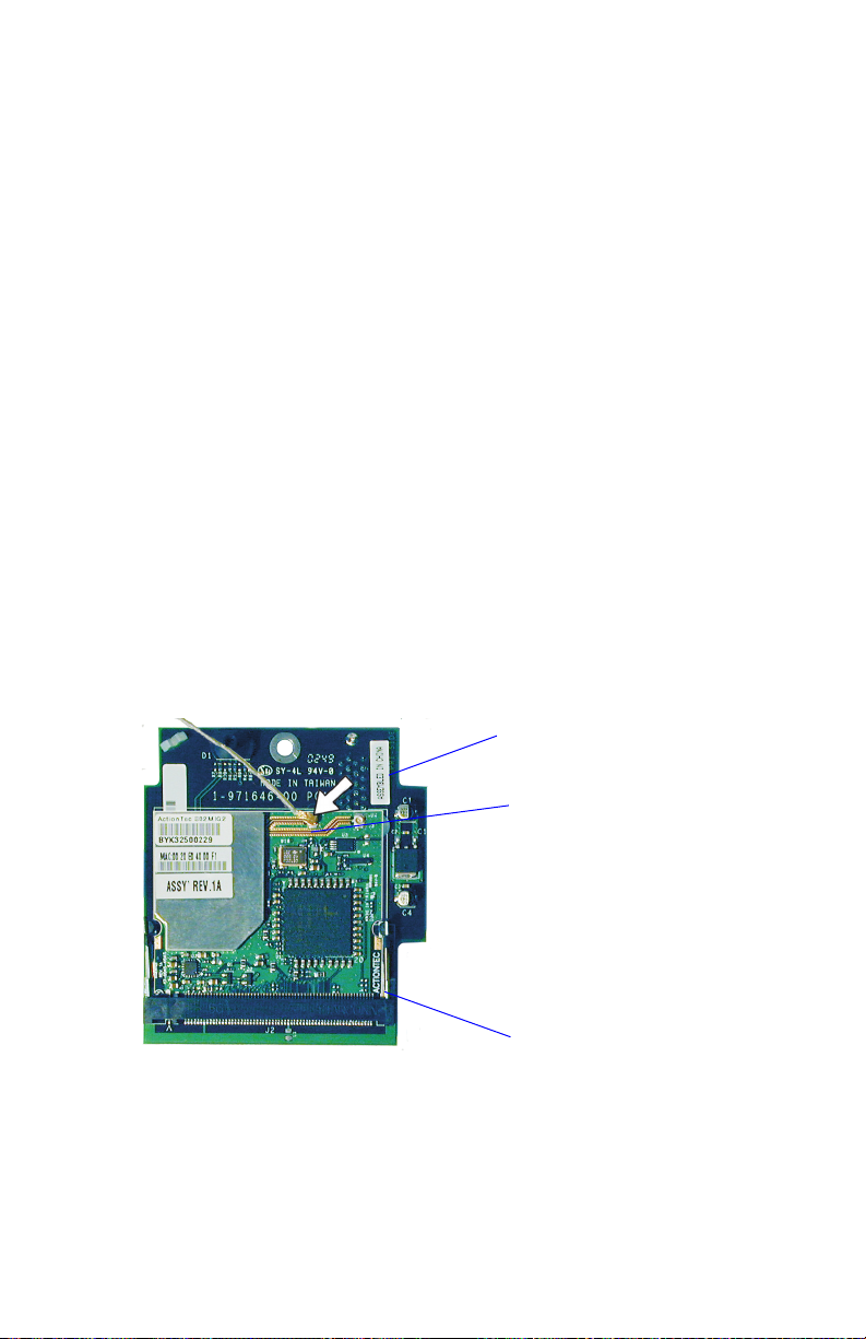
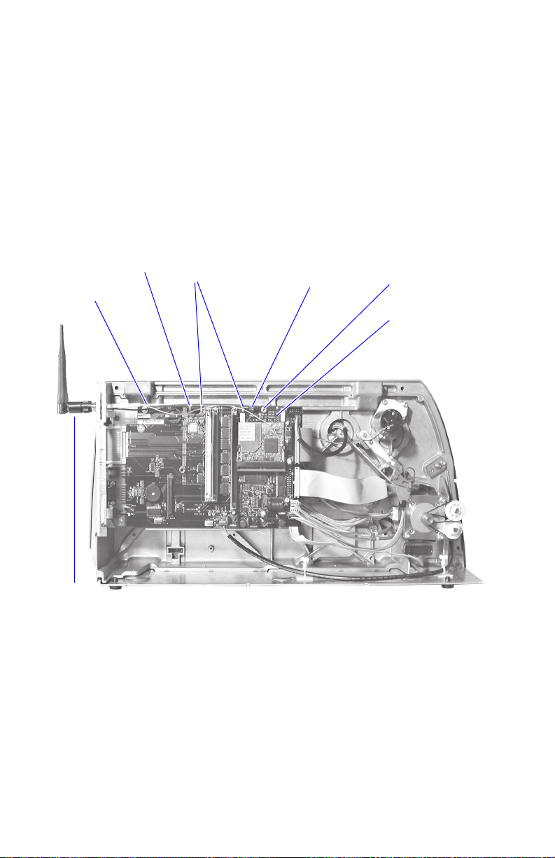
Connect the antenna cable to the radio module, which is factory-
13
fitted on the EasyLAN adapter board, as illustrated below. Support
the upper edge of the radio module with a finger while connecting the
cable.
Adapter board
Connect antenna
cable here
Radio module
Remove the #T20 Torx screw that holds the upper/front part of the
14
CPU board to the power supply unit and replace it with the hexagonal
spacer included in the kit. Keep the screw.
EasyLAN Wireless Interface Kit Installation Instructions 5

Chapter 2 — Physical Installation
Connect the EasyLAN adapter board to the PCI connector (J84) on
15
the CPU board so the hole in the board becomes aligned with the
spacer and secure the board with the #T20 Torx screw.
Route the antenna cable over the SIMMs on the CPU board towards
16
the rear plate and secure it using the cable clips included in the kit.
One clip is factory-fitted on the EasyLAN adapter board and the
other should be fitted in the small hole at the top of the CPU board
immediately to the rear of the memory SIMM sockets.
From the inside of the electronics compartment, insert the antenna
17
connector through the round hole in the rear plate and lock it with
the washer and nut on the outside.
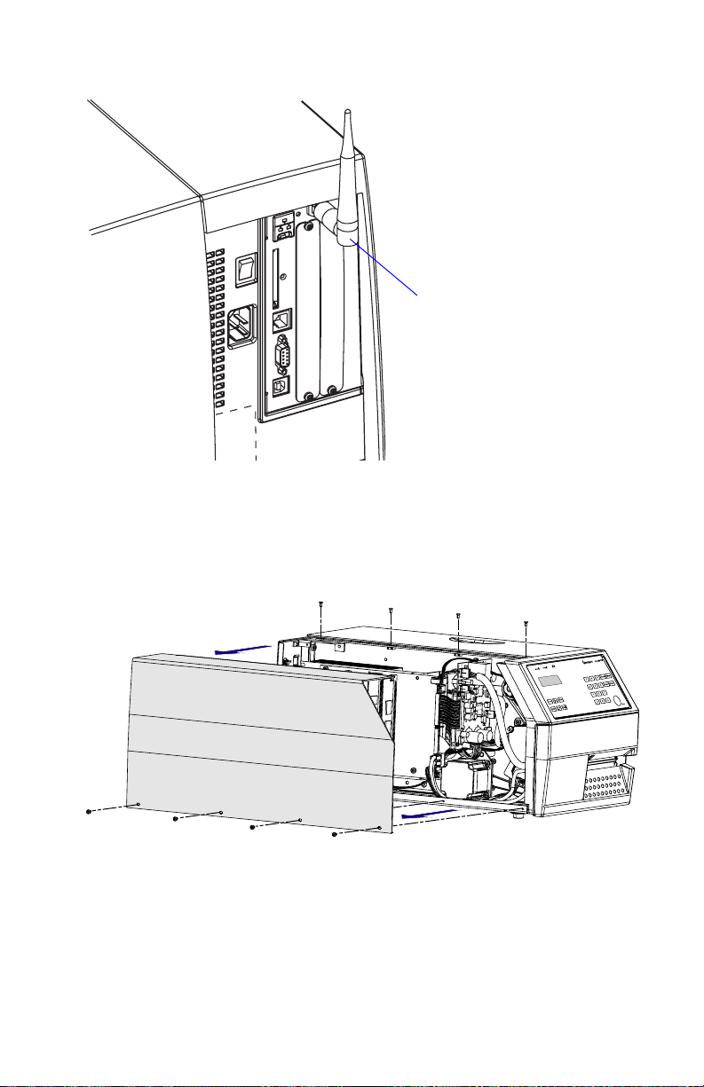
Fit the antenna to the connector of the antenna cable and bend the
18
hinge so the antenna points straight up.
From the outside, insert the thin end of the light guide through the
19
small hole next to the antenna on the rear plate. Press the clear plastic
“lamp” in place. Connect the other end to the black plastic socket
(D1) at the top of the EasyLAN adapter board. Secure it with the
cable tie through the hole at the upper edge of the CPU board.
Put back the cover over the electronics compartment.
20
Route the cable from the display unit above the ribbon motor.
21
Connect the cable to connector J50 at the upper front corner of the
CPU board.
Connect the power cord and switch on the power.
22
Enter the Setup Mode and print the test label “Hardware Info” in
23
Fingerprint or “HW” in IPL to see if the printer detects the EasyLAN
Wireless interface board. For information on how to enter the Setup
Mode and print test labels, refer to the printer’s user’s guide.
6 EasyLAN Wireless Interface Kit Installation Instructions
Chapter 2 — Physical Installation
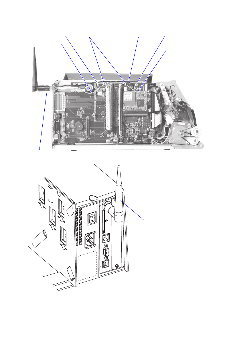
Cable tie
Antenna cable
Antenna
EasyCoder PF2/4i-Series Printer
Light guideCable clips
#T20 Torx screw
and spacer
EasyLAN adapter
board
Antenna
(packed separately when the
EasyLAN Wireless interface is
factory-installed)
EasyCoder PF2/4i-Series Printer, Rear View
EasyLAN Wireless Interface Kit Installation Instructions 7
Chapter 2 — Physical Installation
EasyCoder PM4i Printers
Using a #T20 Torx screwdriver, loosen the four screws that holds the
4
cover along the lower left edge of the bottom plate.
Remove the four screws that hold the cover to the center section.
5
Pull out the cover so you can disconnect the console cable from the
6
CPU board.
Put the cover aside on a soft cloth or similar to avoid scratches.
7
Remove any present EasyLAN Ethernet interface including cables etc.
8
Fit the RJ-45 plug included in the kit into the square hole left by the
RJ-45 Ethernet connector.
Remove the antenna plug, which is snap-locked into the rear plate.
9
8 EasyLAN Wireless Interface Kit Installation Instructions
Chapter 2 — Physical Installation
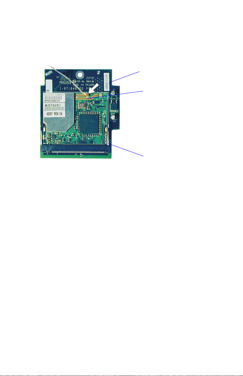
Connect the antenna cable to the radio module, which is factory-
10
fitted on the EasyLAN adapter board, as illustrated below. Support
the upper edge of the radio module with a finger while connecting the
cable.
Adapter board
Connect antenna
cable here
Radio module
Remove the #T20 Torx screw that holds the upper/front part of the
11
CPU board to the power supply unit and replace it with the hexagonal
spacer included in the kit. Keep the screw.
Connect the EasyLAN adapter board to the PCI connector (J84) on
12
the CPU board so the hole in the board becomes aligned with the
spacer and secure the board with the #T20 Torx screw.
Route the antenna cable over the SIMMs on the CPU board towards
13
the rear plate and secure it using the cable clips included in the kit.
One clip is factory-fitted on the EasyLAN adapter board and the
other should be fitted in the small hole at the top of the CPU board
immediately to the rear of the memory SIMM sockets.
From the inside of the electronics compartment, insert the antenna
14
connector through the round hole in the rear plate and lock it with
the washer and nut on the outside.
Fit the antenna to the connector of the antenna cable and bend the
15
hinge so the antenna points straight up.
From the outside, insert the thin end of the light guide through the
16
small hole next to the antenna on the rear plate. Press the clear plastic
“lamp” in place. Connect the other end to the black plastic socket
(D1) at the top of the EasyLAN adapter board. Secure it with the
cable tie through the hole at the upper edge of the CPU board.
EasyLAN Wireless Interface Kit Installation Instructions 9
Chapter 2 — Physical Installation
Put back the cover over the electronics compartment.
17
Route the cable from the display unit above the ribbon motor.
18
Connect the cable to connector J50 at the upper front corner of the
CPU board.
Connect the power cord and switch on the power.
19
Enter Setup Mode and print the test label “Hardware Info” in
20
Fingerprint or “HW” in IPL to see if the printer detects the EasyLAN
Wireless interface board. For information on how to enter the Setup
Mode and print test labels, refer to the printer’s user's guide.
Cable tie
Antenna
cable
Cable clips
Light guide
#T20 Torx screw
and spacer
EasyLAN adapter
board
Antenna
EasyCoder PM4i Printer
10 EasyLAN Wireless Interface Kit Installation Instructions
EasyCoder PM4i Printer, Rear View
EasyCoder PX4/6i Printers
Open the front and right-hand doors.
4
Chapter 2 — Physical Installation
Antenna
(packed separately
when the EasyLAN
Wireless interface is
factory-installed)
Remove the eight #T10 Torx screws that hold the left-hand cover.
5
Put the cover aside on a soft cloth or similar to avoid scratches.
6
EasyLAN Wireless Interface Kit Installation Instructions 11

Chapter 2 — Physical Installation
Remove any present EasyLAN Ethernet interface including cables etc.
7
Fit the RJ-45 plug included in the kit into the square hole left by the
RJ-45 Ethernet connector.
Remove the antenna plug, which is snap-locked into the rear plate.
8
Connect the antenna cable to the radio module, which is factory-
9
fitted on the EasyLAN adapter board, as illustrated below. Support
the upper edge of the radio module with a finger while connecting the
cable.
Adapter board
Connect antenna
cable here
Radio module
Remove the #T20 Torx screw that holds the upper/front part of the
10
CPU board to the power supply unit and replace it with the hexagonal
spacer included in the kit. Keep the screw.
Connect the EasyLAN adapter board to the PCI connector (J84) on
11
the CPU board so the hole in the board becomes aligned with the
spacer and secure the board with the #T20 Torx screw.
Route the antenna cable over the SIMMs on the CPU board towards
12
the rear plate and secure it using the cable clips included in the kit.
One clip is factory-fitted on the EasyLAN adapter board and the
other should be fitted in the small hole at the top of the CPU board
immediately to the rear of the memory SIMM sockets.
12 EasyLAN Wireless Interface Kit Installation Instructions

Chapter 2 — Physical Installation
From the inside of the electronics compartment, insert the antenna
13
connector through the round hole in the rear plate and lock it with
the washer and nut on the outside.
Fit the antenna to the connector of the antenna cable and bend the
14
hinge so the antenna points straight up.
From the outside, insert the thin end of the light guide through the
15
small hole next to the antenna on the rear plate. Press the clear plastic
“lamp” in place. Connect the other end to the black plastic socket
(D1) at the top of the EasyLAN adapter board. Secure it with the
cable tie through the hole at the upper edge of the CPU board.
Put back the cover over the electronics compartment.
16
Connect the power cord and switch on the power.
17
Enter Setup Mode and print the test label “Hardware Info” in
18
Fingerprint or “HW” in IPL to see if the printer detects the EasyLAN
Wireless interface board. For information on how to enter the Setup
Mode and print test labels, refer to the printer’s user's guide.
Antenna
cable
Cable tie
Antenna
EasyCoder PX4/6i Printer
EasyLAN Wireless Interface Kit Installation Instructions 13
Cable clips
Light guide
#T20 Torx screw
and spacer
EasyLAN adapter
board

Chapter 2 — Physical Installation
EasyCoder PX4/6i Printer, Rear View
Antenna
(packed separately
when the EasyLAN
Wireless interface is
factory-installed)
14 EasyLAN Wireless Interface Kit Installation Instructions

Setup (General)
3
is chapter describes the various ways which you can
connect your EasyLAN-equipped printer to your PC,
in order to set the network parameters.
It also provides information about the default user
name and password, which are needed to change the
setup parameters.
EasyLAN Wireless Interface Kit Installation Instructions 15

Chapter 3 — Setup (General)
Setting up Network Parameters
ere are several different ways you can set up your network parameters:
• Connect the printer to a PC and run the PrintSet program which
can be found on the EasyLAN CD and on the Intermec website.
PrintSet requires a PC running Windows 98 or later. is is the
easiest and most convenient way to set up your printer.
• Fingerprint:
Establish a serial (RS-232) communication with the printer and
set it up using Fingerprint setup strings or setup files. IP address,
subnet mask, default router, and name server can also be set
using the printer’s built-in keyboard. See Chapter 4, “Setup in
Fingerprint.” e only requirement on the PC side is a terminal
program that can transmit and receive ASCII characters on an
RS-232 line. Fingerprint users can also create a configuration file
on a CompactFlash card that can be used to update the printer
automatically. is is particularly convenient if you are planning to
set up several printers with the same network parameters. Please see
“Setup with CompactFlash” on the next page.
• IPL:
Establish a serial (RS-232) communication with the printer and
set it up using IPL commands. You need a PC with a terminal
program that can transmit and receive ASCII characters. Select the
method of obtaining IP address, subnet mask, default router, and
name server automatically from the server using the printer’s builtin keyboard. is requires a server that supports DHCP and/or
BOOTP. See Chapter 5, “Setup in IPL.”
Establishing Serial Communications
To modify your network parameters, you need to first establish a serial
connection with a PC using a cable. is applies both to setup using the
PrintSet program and setup using Fingerprint or IPL commands.
To set up a serial connection
Connect a common RS-232 cable between a serial port, for example
1
COM1, on the PC and the RS-232 port on the printer.
Start a terminal program, such as Microsoft HyperTerminal.
2
16 EasyLAN Wireless Interface Kit Installation Instructions

Chapter 3 — Setup (General)
Set up the printer and the terminal for the communication parameters
3
and type of handshake.
Press the <i> key on the printer’s keyboard to check that the printer
4
uses either auto or an RS-232 serial channel as I/O channel.
Check that the connection is working.
5
Also refer to your printer’s user’s guide and the Intermec Fingerprint
Programmer’s Reference Manual or the IPL Programmer’s Reference
Manual.
Setup with CompactFlash (Fingerprint only)
If you are planning to update several printers with the same network
setup parameters, you may want to consider creating a configuration file
for this purpose. Once created, you copy the file to a CompactFlash card,
insert the card in the printer, restart the printer and the parameters will
be set up automatically.
To Create a CompactFlash Card with a Configuration File
Open a new document in a text editor.
1
Write a Fingerprint program (syntax is described in Chapter 4, “Setup
2
in Fingerprint”), that sets the desired network parameters. Here is an
example of what it might look like:
10 RUN"su -p pass admin"
20 SETUP "wlan","SSID","Milkyway"
30 SETUP "wlan","WEP1","0x1138170147"
40 SETUP "wlan","AUTH","SHARED"
50 SETUP "wlan","WEP_KEY","1"
60 SETUP "8021x","EAP_TYPE","OFF"
Save your file as “WLAN.PRG” and copy it to the CompactFlash
3
card.
Now, create the file which executes the update itself. Open a new
4
document in a text editor, and write the following:
RUN "card1:WLAN.PRG"
Save your file as “AUTOEXEC.BAT” and copy it to the
5
CompactFlash card.
EasyLAN Wireless Interface Kit Installation Instructions 17

Chapter 3 — Setup (General)
User and Password
By default, the user is admin and the password is pass. Initially, this
user and password gives unrestricted access to all setup parameters,
except Region. Changing the Region requires a special password, which
is distributed only to authorized personnel.
Use of the EasyLAN Wireless network interface with an
incorrect REGION setting may be in violation of applicable
laws.
18 EasyLAN Wireless Interface Kit Installation Instructions

Setup in Fingerprint
4
is chapter explains how to set up the wireless
network communication in printers running Intermec
Fingerprint v8.40 (or later). e only requirement on
the PC side is a terminal program that can transmit
and receive ASCII characters on an RS-232 line.
us, this method is recommended when you do not
have the opportunity to run the PrintSet program,
for example when you are using an operating system
other than Windows.
For information on how to set up the network
communication in printers running IPL, refer to
Chapter 5.
EasyLAN Wireless Interface Kit Installation Instructions 19

Chapter 4 — Setup in Fingerprint
Setting Up Wireless Communications
is section describes how to perform some common tasks such as
changing user and passwords, as well as setting individual network
parameters with Fingerprint commands.
General
Once a wired serial communication is established, you can use
Fingerprint setup strings or setup files to set up the necessary EasyLAN
Wireless parameters. All settings are saved in files on the printer flash
memory. If a factory default upgrade is performed, all settings described
in this section are reset to (factory) default values.
e default allowed user is admin. All settings are restricted to readonly for all users except the allowed user, who can change all settings. If
unauthorized access is attempted, error 1076 (Operation not permitted)
will occur. Settings beginning with a period “.” character are readprotected from non-authorized users. Some settings are not possible to
read even by the allowed user, for instance WEP keys, which return the
same string regardless of the actual key.
Display Current User
To display who the current user is in Fingerprint, the “whoami”
command is used.
Syntax:
RUN"whoami"
Note: is command is case-sensitive.
e command echoes the current user to the standard out channel.
Example:
RUN"whoami"
user
Ok
20 EasyLAN Wireless Interface Kit Installation Instructions

Chapter 4 — Setup in Fingerprint
Changing User
To change the current user in Fingerprint, the “su”command is used.
Syntax:
RUN"su [-p <password>] <user>"
su requests the password for <user>, and switches to that user after
checking the password file.
Valid <user> names are admin and user.
Everyone can become user even if user’s password is set.
No password is requested if the current user already is the one to switch
to.
e option is as follows:
-p password Do not query for a password; use the one supplied at
the command line.
Note: Everything is case sensitive (user name, su command,
passwords).
Examples:
To become “admin”.
RUN"su admin"
Password:[enter password (default: pass)]
Ok
Or:
RUN"su -p pass admin": RUN"whoami"
admin
To switch back to user:
RUN"su user"
EasyLAN Wireless Interface Kit Installation Instructions 21

Chapter 4 — Setup in Fingerprint
Changing Passwords
To change the password for a user in Fingerprint, the “passwd”command
is used.
Syntax:
RUN"passwd [<user>]"
passwd changes the user’s password. First, the user is prompted for the
current password (if it exists). If the current password is correctly typed,
a new password is requested. e new password must be entered twice
to avoid typing errors. e new password’s total length must be less
than 128 characters. Numbers, uppercase letters and meta characters are
encouraged. Valid user names are admin and user.
You can also use this command:
RUN"passwd <user> '<oldpasswd>' '<newpasswd>' '<newpasswd>'
Examples:
To change password for the current user (user, without password):
RUN"passwd"
Changing local password for user.
New password:[enter new password]
Retype new password:[enter new password]
To change password for “admin”:
RUN"passwd admin"
Changing local password for admin.
Old password:[enter current password]
New password:[enter new password]
Retype new password:[enter new password]
Note: You do not have to change to the user whose password is
changed.
Active
While setting up the printer’s network settings, it is preferable that
the changes do not take effect until all the changes have been made.
All settings are saved to non-volatile memory immediately after the
command has been given, but they are not committed to the NIC/driver
until these “current” settings have been “activated.”
A reboot will cause the current settings to be used. e alternative to
22 EasyLAN Wireless Interface Kit Installation Instructions

Chapter 4 — Setup in Fingerprint
rebooting the printer is the “ACTIVE” setting. Setting this to anything
other than a “0” will cause the current settings to be activated. Reading
the ACTIVE setting will indicate whether the current settings are being
used or not. 0 indicates that the current settings are not active (changes
have been made since startup or last non-zero setting of ACTIVE). 1
indicates that the settings are being used. ACTIVE cannot be set to 0
explicitly (but is implicitly set to 0 by changing another setting). Any
changes made on the web page(s) will be activated when the user submits
the form (given that the settings are correctly entered).
In Fingerprint, there are two sections with an “ACTIVE” setting: “wlan”
for wireless LAN settings, and "8021x" for IEEE 802.1x settings.
Setting ACTIVE to “1” in either section will cause the settings in both
sections to become active - given that ACTIVE was "0" in both sections.
Note: Both sections are controlled by the “setup wlan”
restrictions.
SETUP "wlan","ACTIVE","1" activates the current settings in the
“wlan” section and any changes made in the “8021x” section (forcing a
re-association).
SETUP "8021x","ACTIVE","1" activates the current settings in the
“8021x” section and any changes made in the “wlan” section (forcing a
re-association).
SETUP GET/WRITE for “ACTIVE” will get 1 if the current settings
are in use, 0 if a setting has been changed.
EasyLAN Wireless Interface Kit Installation Instructions 23

Chapter 4 — Setup in Fingerprint
SSID (Network Name)
e SSID (Service Set Identifier) is 0-32 characters used to differentiate
wireless LANs that overlap in frequency and physical coverage area.
An empty SSID string signifies that the printer will associate with any
network. By default SSID is INTERMEC.
Non-alphanumeric octets are entered by “%HH” (a percent sign and two
hexadecimal digits (0-9, a-f, A-F) representing the value of the character).
Example: “12%2034” is equivalent to “12 34”. e percent sign is
represented by “%25”. e SSID can be changed by authorized users
and on the printer’s web page.
SETUP "wlan","SSID","milkyway"
Sets SSID to “milkyway”.
SETUP GET/WRITE reports the SSID.
e SSID is shown on the test label and on the printer’s home page.
WEP
Note: WEP functionality is only supported by Fingerprint
8.10 or later.
WEP (Wired Equivalent Privacy) uses a secret (40 or 104 bits long)
together with a 24-bit “IV” (Initialization Vector) to form a key used to
encrypt the data sent over radio.
e printer can have up to four WEP 64 and/or WEP 128 keys. ere
is a key selection setting for selecting the key that will be used when
transmitting. Its value is 0-4 (0 signifying that WEP is disabled, or that
WEP keys will be generated via 802.1x or WPA; 1-4 selecting one of
the configured keys). It is possible to select an unconfigured key, which
disables WEP. By default, WEP is disabled, and no keys are configured.
WEP keys are entered either in a hexadecimal notation or in an
alphanumerical notation. A string starting with “0x” (a zero followed
by a lowercase x) followed by 10 or 26 characters is interpreted as a
WEP key in hex-notation; anything else is interpreted as a WEP key in
alphanumerical notation. If a key is set to the empty string it is said to
be unconfigured. If the wireless data is WEP encrypted, it is possible to
change the WEP keys on the printer’s home page.
24 EasyLAN Wireless Interface Kit Installation Instructions

Chapter 4 — Setup in Fingerprint
Examples:
SETUP "wlan","WEP1","0x1138170147"
Sets key #1 (WEP 64, hexadecimal)
SETUP "wlan","WEP2","abcde"
Sets key #2 (WEP 64, alphanumerical)
SETUP "wlan","WEP3","0x123456789abcdef0123456789a"
Sets key #3 (WEP 128, hexadecimal)
SETUP "wlan","WEP4","Manufacturing"
Sets key #4 (WEP 128, alphanumerical)
SETUP "wlan","WEP2",""
Removes key #2
SETUP "wlan",".WEP_KEY","0"
Disables WEP
SETUP "wlan",".WEP_KEY","1"
Selects WEP key #1 for use in transmission (0-4 accepted)
SETUP WRITE/GET for WEP1-4 returns empty string if that key is
not configured, “****” otherwise.
It is not possible for any user to read the WEP key(s).
WEP Enabled/Disabled is shown on the printer's web page and the
network test label. WEP is considered disabled if no key has been
selected, or if the selected key is not configured.
802.11 Authentication
Note: e AUTH function is only supported by Fingerprint
8.72 or later.
e 802.11 standard has two subtypes of network authentication
services: Shared Key and Open System. Shared Key assumes that each
wireless station has received a secret shared key (WEP key) over a secure
channel. If Shared Key is selected but no WEP keys are configured, the
printer will automatically use Open System authentication, which means
that any wireless station can request authentication.
In addition to the OPEN and SHARED settings, EasyLAN Wireless can
also be set to AUTO authenticate. With this setting active, the network
adapter will decide what to do. However, this setting has been found
EasyLAN Wireless Interface Kit Installation Instructions 25

Chapter 4 — Setup in Fingerprint
to cause problems in certain environments, which is why the two other
alternatives have been made available.
Example:
SETUP "wlan","AUTH","SHARED"
Shared Key Authentication will be used.
e AUTH setting can also be changed via the printer’s homepage,
provided the user is logged in as Admin.
WPA
Note: WPA functionality is only supported by Fingerprint
8.50 or later.
WPA (Wi-Fi Protected Access) is compatible with the 802.11i standard
and was developed to counter the weaknesses of WEP and some flaws in
the key distribution of 802.1x.
WPA can be turned ON or OFF, and the default setting is WPA ON. A
Pre-Shared Key (PSK, also known as pass phrase) can be used instead of
802.1x authentication. e PSK must be between 8 and 64 characters
long. A standardized algorithm is used to convert the PSK to a 256-bit
key. If the PSK is exactly 64 characters in length, it is interpreted as a
hexadecimal string specifying the 256-bit key directly. If the PSK is set,
802.1x settings are not used. It is not possible for any user to read the
WPA PSK value.
Note: It is not enough to set ACTIVE (page 22) to 1, the
printer has to be rebooted before WPA changes will take effect.
Examples:
SETUP "wlan","WPA","ON"
Enables WPA.
SETUP "wlan","WPA","OFF"
Disables WPA.
SETUP "wlan","WPA_PSK","mykey"
Sets WPA pre-shared key to “mykey”.
26 EasyLAN Wireless Interface Kit Installation Instructions

Chapter 4 — Setup in Fingerprint
SETUP "wlan","WPA_PSK",""
Removes the pre-shared key.
SETUP GET/WRITE returns an empty string if the key has not been
set, and “****” for any pre-shared key regardless of length.
Roaming Bias
In an environment with several access points, the network adapter may
have problems deciding which access point to connect to. In order to
make the adapter less inclined to switch access points, it is possible for
the admin to change the ROAM setting.
ROAM can be set to a value of 1,2, or 3. A higher ROAM value means
that the network adapter is less inclined to roam. e default setting is 1.
Example:
SETUP "wlan","ROAM","2"
Sets roaming inclination to medium.
802.1x
Note: 802.1x functionality is supported only by Fingerprint
8.40 or later.
To increase security in wireless networks, IEEE 802.1x was introduced.
is method authenticates stations to the network (and in some cases
vice versa), via a supplicant subsystem so that only authorized devices can
get access to the network.
To increase the available memory, the supplicant subsystem can be
disabled if:
• 802.1x is disabled by setting EAP_Type and WPA to OFF.
• the printer has 8MB of SDRAM installed.
• there is no EasyLAN Wireless interface installed.
Supported EAP Types
EasyLAN Wireless supports these EAP types:
• TTLS: With PAP or MSCHAPv2 in the tunnel. Token Card (GTC
with static password), MD5-Challenge, and MSCHAPv2 may also be
run inside an EAP session.
EasyLAN Wireless Interface Kit Installation Instructions 27

Chapter 4 — Setup in Fingerprint
• LEAP: Cisco proprietary EAP type, requiring a Cisco access point.
• PEAP: With EAP/MSCHAPv2, EAP/Token Card (static password),
or EAP/MD5-Challenge in the tunnel.
802.1x Settings
ese 802.1x parameters can be configured:
• EAP type: TTLS (default), LEAP, or PEAP, and can also be set to
OFF to disable 802.1x. When selecting PEAP or TTLS, the inner
authentication type will be changed appropriately for the selected
EAP type. For example, if TTLS is selected with inner authentication
type MSCHAPv2, changing the EAP type to PEAP changes the inner
authentication type to EAP/MSCHAPv2.
Note: If you start the printer with EAP type set to OFF and
then change the EAP type to TTLS, LEAP, or PEAP, you need
to reboot the printer for your new settings to take effect. You
cannot set ACTIVE to “1” to enable 802.1x settings without
rebooting.
• User name and password for logging onto the network. e default is
“anonymous”/“anonymous”.
• Outer name (TTLS only): e EAP identity passed in the clear in
TTLS. e default is “anonymous”.
• Inner Authentication type (TTLS and PEAP only): MSCHAPv2
(default), PAP (TTLS only), EAP/MSCHAPv2, EAP/MD5, or
EAP/GTC. Because PEAP uses EAP in the tunnel, for PEAP
“MSCHAPv2” and “EAP/MSCHAPv2” are equivalent settings.
TTLS can use other authentication protocols directly, so you need to
specify whether EAP will be used or if the protocol will run directly in
the tunnel.
• CA Certificate (TTLS and PEAP only): A certificate which should
contain the public key corresponding to the private key that was used
to sign the server's certificate, or the top certificate in a chain leading
to the server's certificate. e default is /rom/intermec.cer, provided
by Intermec and delivered with firmware containing the supplicant
functionality. e default certificate can be overridden by loading
another certificate in PEM, DER (.der, .cer), or PKCS #12 (.p12,
.pfx) format.
28 EasyLAN Wireless Interface Kit Installation Instructions

Chapter 4 — Setup in Fingerprint
• Two Common names (TTLS and PEAP only): Two different
common names may be configured. If both are empty, the supplicant
will accept certificates regardless of the server certificate’s common
name. If the first common name is configured, the common name
(CN) of the server’s certificate must match the first common name.
If both common names are configured, the server’s certificate must
match one of them. e default is “” (accepts any common name).
• Validate server certificate (TTLS and PEAP only): Verifies that the
installed CA certificate is the root of the server certificate. e default
is ON.
Note: Adverse effects on validation can occur if a real-time
clock (RTC) is not installed. Without an RTC, the current
time cannot be reliably read and validation does not take into
account the current date. Validation may still occur, but less
reliably than with an RTC.
For all 802.1x parameters, string length is limited to 96 characters.
For all parameters applicable to TTLS or PEAP: Selecting another EAPtype disables these parameters, but does not erase their settings.
Using Certificates
When an overriding certificate is installed, it is converted to DER format
and copied to a specific location (/c/ADMIN/root.cer) so that accidental
removal is unlikely. You do not need to keep additional copies of the
certificate on the printer after you install the certificate.
Some certificate formats (notably PKCS #12) encrypt data using a pass
phrase. To import certificates that include anything other than an empty
pass phrase, the pass phrase is given in the same string as the path to the
certificate file. e pass phrase is never stored on the printer and is used
only once to convert the public key to a non-encrypted format.
To reinstall the default root CA certificate, install /rom/intermec.cer, or
remove the /c/ADMIN/root.cer file.
EasyLAN Wireless Interface Kit Installation Instructions 29

Chapter 4 — Setup in Fingerprint
Examples
SETUP "8021x","EAP_TYPE","TTLS|LEAP|PEAP|OFF"
Sets preferred EAP type.
SETUP "8021x",".EAP_USER","Admin01"
Sets logon username to “Admin01”.
SETUP "8021x","EAP_PASS","InfoTech"
Sets logon password to “InfoTech”.
Note: It is not possible for any user to read the EAP_PASS
value.
SETUP "8021x","TTLS_USER","Manufacturing"
Sets TTLS outer name to “Manufacturing”.
SETUP "8021x","INNER_AUTH","PAP|MSCHAPv2|EAP/
MSCHAPv2|EAP/MD5|EAP/GTC"
Sets inner authentication type (TTLS/PEAP only).
SETUP "8021x","CA_CERT","/tmp/mycacert.cer"
Installs overriding CA certificate (TTLS/PEAP only).
SETUP "8021x","CA_CERT","/tmp/mycacert.pfx@
verysecret"
Installs overriding CA certificate (TTLS/PEAP only), encrypted with the
pass phrase “verysecret”.
SETUP "8021x",".SERVER_CN1","Printer33"
Sets common name 1 to “Printer33” (TTLS/PEAP only).
SETUP "8021x",".SERVER_CN2","Printer34"
Sets common name 2 to “Printer34” (TTLS/PEAP only).
SETUP "8021x","VALIDATE","ON|OFF"
Enables or disables validation of the server certificate (TTLS/PEAP
only).
SETUP WRITE/GET for all settings returns the set value, except for
EAP_PASS which always returns “****” if configured, and for “CA_
CERT” which returns the common name of the last certificate authority
successfully installed (but not the path to the file).
An additional item is “STATE”, which is read-only for all users:
30 EasyLAN Wireless Interface Kit Installation Instructions

Chapter 4 — Setup in Fingerprint
SETUP GET "8021x","STATE",A$
Gets the supplicant state: “Disabled”, “Failed”, “Authenticating”, or
“Authenticated”.
Note: If you start the printer with EAP type set to OFF and
then change the EAP type to TTLS, LEAP, or PEAP, you need
to reboot the printer for your new settings to take effect. Until
you reboot, STATE returns “Disabled.”
802.1x supplicant state, EAP type, outer name, inner authentication,
installed root certificate, server common names, and server certificate
validation can be seen on the printer's web page and the network test
label.
Reading Other Wireless Connection Variables
In addition to SSID, WEP, WLAN, and 802.1x settings, the following
information can be read using SETUP GET instructions:
• Active channel
• MAC address of the access point
• Signal strength
• Speed
• Region
1
/. e information is also given on the network test label and on the
1
2
web page.
2
/. e current region is also presented on the web page.
3
/. Active channel and signal strength is shown in the printer’s display
window when the <i> key is pressed.
1,3
1
1,3
Active Channel
802.11b/g operates on a number of different channels, corresponding
to different frequencies. e printer scans for a suitable access point and
channel. e selected channel can be read from the printer. e readonly setup-variable “CHANNEL” can assume values from 0 up to 14
depending on the region setting. 0 signifies that an association has not
yet been made, 1-14 is the currently selected channel.
EasyLAN Wireless Interface Kit Installation Instructions 31

Chapter 4 — Setup in Fingerprint
SETUP GET "wlan","CHANNEL",A$
gets the current channel in A$.
Access Point Information
e printer associates with an access point. e read-only setup-variable
“AP_MAC” will assume the MAC address of the access point that the
printer is currently associated with. If no association has been performed,
the value of “AP_MAC” is “00:00:00:00:00:00”.
SETUP GET "wlan","AP_MAC",A$
gets the MAC address of the associated access point in A$.
Signal Strength
An important tool when working out problems with wireless LANs
is a signal strength meter. e printer monitors the received signal
strength, and makes it available to the user. e read-only setup variable
“SIGNAL” assumes the value of the current received signal strength. e
value may vary from 0 (no signal) to 100 (maximum strength).
SETUP GET "wlan","SIGNAL",A$
gets signal strength in A$.
Speed
Depending on different (radio) network parameters, such as distribution
of access points, frequencies, number of clients, etc., the network
card may select a lower speed than the maximum for better overall
performance. e selected speed (rounded down to whole Mbps) can be
read from the printer. e read-only setup-variable “SPEED” can assume
values from 0 up to 54 (Mbps).
SETUP GET "wlan","SPEED",A$
gets the speed in A$.
Region (a.k.a. Regulatory Domain)
Some countries and regulatory authorities only allow the use of a subset
of the 14 channels specified in the 802.11b/g standard. To make the
product world configurable the setup variable “.REGION” is used.
e region can only be set by personnel authorized by Intermec. If the
32 EasyLAN Wireless Interface Kit Installation Instructions

Chapter 4 — Setup in Fingerprint
wrong region/domain is set, please contact your Intermec representative
immediately. Continued use of the EasyLAN Wireless network interface
with an incorrect REGION setting may be in violation of applicable
laws.
e region setting will not be reset to default, even if a factory default
upgrade is performed.
e following regulatory domains are implemented:
Regulatory Domains
Value Countries Allowed Channels
FCC (or USA) U.S.A 1-11 (default)
IC (or Canada) Canada 1-11
ETSI (or EU) EU countries1 + Iceland,
Liechtenstein, Norway, and
Switzerland
MKK (or Japan) Japan 1-14
1
/. Certain restrictions apply to outdoor use in France.
SETUP GET "wlan",".REGION",A$
1-13
Gets the active region in A$.
Reading Wireless Connection Setup
All settings can be returned to the host via a specified serial
communication port, usually "uart1:", using the Fingerprint instruction
SETUP WRITE "wlan" or SETUP WRITE "8021x".
Example:
SETUP WRITE "wlan","uart1:"
Provided the current user is logged in as admin, this will produce a full
list of wireless setup parameters:
SSID qwerty
WEP1 ****
WEP2 ****
WEP3
WEP4
.WEP_KEY 0
AUTH SHARED
WPA OFF
EasyLAN Wireless Interface Kit Installation Instructions 33

Chapter 4 — Setup in Fingerprint
WPA_PSK
.REGION USA (FCC)
ROAM 1
# CHANNEL 11
# AP_MAC 00:10:40:25:ee:a9
# SIGNAL 49
# SPEED 11
ACTIVE 1
Setting Up Network Parameters
In this document, the use of setup strings or setup files are described.
Network parameters could also be set via the printer’s built-in keyboard
as described in the printer user’s guide.
New Line
Set the New Line parameter using a setup string or setup file:
SETUP"NET-COM,NET1,NEW LINE,CR/LF"
SETUP"NET-COM,NET1,NEW LINE,LF"
SETUP"NET-COM,NET1,NEW LINE,CR"
Default is CR/LF.
IP Selection Method
ere are four methods for setting the IP address. DHCP, BOOTP, and
DHCP+BOOTP let the server assign a temporary IP address to the
printer. e method to choose depends on the server. DHCP, BOOTP,
and DHCP+BOOTP also sets the subnet mask, default router, and
name server automatically. If the server neither supports DHCP nor
BOOTP, or if you want to set a permanent IP address manually, use the
MANUAL option. In this case, you will also have to set the subnet mask,
default router, and name server manually via the printer’s keyboard.
Always consult the network administrator before assigning
a permanent IP address to avoid having more than one
device with the same IP address in the network.
Set the IP selection method parameter using a setup string or setup file
(by default only allowed for admin1):
34 EasyLAN Wireless Interface Kit Installation Instructions

Chapter 4 — Setup in Fingerprint
SETUP"NETWORK,IP SELECTION,DHCP+BOOTP" (default)
SETUP"NETWORK,IP SELECTION,MANUAL"
SETUP"NETWORK,IP SELECTION,DHCP"
SETUP"NETWORK,IP SELECTION,BOOTP"
1
/. However, anybody can change the IP selection method from the
printer’s keyboard using the Setup Mode.
IP Address
If you have selected MANUAL as manual selection method, you can
assign a permanent IP address to the printer:
SETUP"NETWORK,IP ADDRESS,nnn.nnn.nnn.nnn"
Subnet Mask
If you have selected MANUAL as manual selection method, you can
specify a netmask for the printer:
SETUP"NETWORK,NETMASK,nnn.nnn.nnn.nnn"
Default Router
If you have selected MANUAL as manual selection method, you can
specify a default router for the printer:
SETUP"NETWORK,DEFAULT ROUTER,nnn.nnn.nnn.nnn"
Name Server
If you have selected MANUAL as manual selection method, you can
specify a name server for the printer:
SETUP"NETWORK,NAME-SERVER,nnn.nnn.nnn.nnn"
Finishing the Setup
You can now disconnect the printer from the PC and use your web
browser to test the wireless communication as described in Chapter 6,
assuming that there is a working wireless LAN and the printer is inside
the coverage area of an access point.
EasyLAN Wireless Interface Kit Installation Instructions 35

Chapter 4 — Setup in Fingerprint
36 EasyLAN Wireless Interface Kit Installation Instructions

Setup in IPL
5
is chapter explains how to set up the wireless
network communication in printers running IPL
v2.40 (or later). e only requirement on the PC side
is a terminal program that can transmit and receive
ASCII characters on an RS-232 line. us, this
method is recommended when you do not have the
opportunity to run the PrintSet program, for example
because you use some other operating system than
Windows.
For information on how to set up the network
communication in printers running Fingerprint, refer
to Chapter 4, “Setup in Fingerprint.”
EasyLAN Wireless Interface Kit Installation Instructions 37

Chapter 5 — Setup in IPL
Setting Up Wireless Communications
is section describes how to perform some common tasks such as
changing user and passwords, as well as setting individual network
parameters with IPL commands.
General
Once a wired serial communication is established, you can use IPL
commands to set up the necessary EasyLAN Wireless parameters. All
settings are saved in files on the printer flash memory. If a factory default
upgrade is performed, all settings described in this section are set to their
(factory) default values.
e default allowed user is “admin”. All settings are restricted to readonly for all users except the allowed user, who can change all settings.
Settings beginning with a period “.” character are read-protected from
non-authorized users. Some settings are not possible to read even by
the allowed user, for instance WEP keys, which return the same string
regardless of the actual key.
Display Current User
To display who the current user is in IPL, the “whoami” command is
used.
<STX><ESC>.x,whoami<ETX>
Changing User
To change the current user in IPL, the “xu” command is used.
<STX><SI>xu,user,password<ETX>
xu switches to the specified user after checking the password against the
password file.
Valid user names are admin and user.
Everyone can become user even if user’s password is set.
Example:
<STX><SI>xu,admin,pass<ETX>
changes the current user to “admin” provided that the admin’s password
is “pass.”
38 EasyLAN Wireless Interface Kit Installation Instructions

Chapter 5 — Setup in IPL
Changing Passwords
To change the password for a user in IPL, the “passwd”command is used.
<STX><SI>xp,user,oldpass,newpass,retyped<ETX>
is command changes the user’s password. If the current password
(oldpass) is correctly typed, the password will be changed to
newpass. e new password must be entered twice to avoid typing
errors. e new password’s total length must be less than 128 characters.
Numbers, uppercase letters, and metacharacters are encouraged. Comma
signs (,) are not allowed. Valid user names are admin and user.
Example:
<STX><SI>xp,admin,pass,?pw,?pw<ETX>
Active
While setting up the printer’s network settings, it is preferable that
the changes do not take effect until all the changes have been made.
All settings are saved to non-volatile memory immediately after the
command has been given, but they are not committed to the NIC/driver
until these “current” settings have been “activated.”
A reboot will cause the current settings to be used. e alternative to
rebooting the printer is the “ACTIVE” setting. Setting this to anything
other than a “0” will cause the current settings to be activated. Reading
the ACTIVE setting will indicate whether the current settings are being
used or not. 0 indicates that the current settings are not active (changes
have been made since startup or last non-zero setting of ACTIVE). 1
indicates that the settings are being used. ACTIVE cannot be set to 0
explicitly (but is implicitly set to 0 by changing another setting). Any
changes made on the web page(s) will be activated when the user submits
the form (given that the settings are correctly entered).
Unlike Fingerprint, IPL has no distinction between setup sections.
<STX><SI>ws,ACTIVE,1<ETX>
Sets ACTIVE to 1
<STX><SI>wt,ACTIVE<ETX>
Transmits ACTIVE status
EasyLAN Wireless Interface Kit Installation Instructions 39

Chapter 5 — Setup in IPL
SSID (Network Name)
e SSID (Service Set Identifier) is 0-32 characters used to differentiate
wireless LANs that overlap in frequency and physical coverage area.
An empty SSID string signifies that the printer will associate with any
network. By default SSID is “INTERMEC”.
Non-alphanumeric octets are entered by “%HH” (a percent sign and two
hexadecimal digits (0-9, a-f, A-F) representing the value of the character).
Example: “12%2034” is equivalent to “12 34”. e percent sign is
represented by “%25’. e SSID is possible to change by allowed users
on the printer’s web page.
<STX><SI>ws,SSID,qwerty<ETX>
Sets SSID to “qwerty”.
<STX><SI>wt,SSID<ETX>
Transmits current SSID.
e SSID is shown on the test label and on the printer’s home page.
WEP
Note: WEP is only supported by IPL v2.10 or later.
WEP (Wired Equivalent Privacy) uses a secret (40 or 104 bits long)
together with a 24-bit “IV” (Initialization Vector) to form a key used to
encrypt the data sent over radio.
e printer can have up to four WEP 64 and/or WEP 128 keys. ere
is a key selection setting to select which key that will be used when
transmitting. Its value will be 0-4 (0 signifying that WEP is disabled,
or that WEP keys will be generated via 802.1x or WPA; 1-4 selecting
one of the configured keys). It is possible to select an unconfigured key
(this disables WEP). By default, WEP is disabled, and no keys will be
configured.
WEP keys are entered either in a hexadecimal notation or in an
alphanumerical notation. A string starting with “0x” (a zero followed
by a lower-case x) followed by 10 or 26 characters is interpreted as a
WEP key in hex-notation; anything else is interpreted as a WEP key in
alphanumerical notation. If a key is set to the empty string it is said to
be unconfigured. If the wireless data is WEP encrypted, it is possible to
change the WEP keys on the printer’s home page.
40 EasyLAN Wireless Interface Kit Installation Instructions

Chapter 5 — Setup in IPL
Examples:
<STX><SI>ws,WEP1,0x1138170147<ETX>
Sets key #1 (WEP 64, hexadecimal)
<STX><SI>ws,WEP2,Admin<ETX>
Sets key #2 (WEP 64, alphanumerical)
<STX><SI>ws,WEP3,0x123456789abcdef0123456789a<ETX>
Sets key #3 (WEP 128, hexadecimal)
<STX><SI>ws,WEP4,Manufacturing<ETX>
Sets key #4 (WEP 128, alphanumerical)
<STX><SI>ws,WEP2,<ETX>
Removes key #2
<STX><SI>ws,.WEP_KEY,0<ETX>
Disables WEP
<STX><SI>ws,.WEP_KEY,1<ETX>
Select WEP key 1 for use in transmission (0-4 accepted).
<STX><SI>wt,WEP1<ETX>
Transmits WEP key #1 (empty string if that key is not configured, “****”
otherwise). WEP2-4 transmits key #2-4.
<STX><SI>wt,.WEP_KEY<ETX>
Transmits selected WEP key: 0 when disabled, 1-4 when enabled. Only
allowed users may see this. It is not possible for any user to read the WEP
key(s).
WEP Enabled/Disabled is shown on the printer web page and the
network test label. WEP is considered disabled if no key has been
selected, or if the selected key is not configured.
802.11 Authentication
Note: e AUTH function is only supported by IPL 2.72 or
later.
e 802.11 standard has two subtypes of network authentication
services: Shared Key and Open System. Shared Key assumes that each
wireless station has received a secret shared key (WEP key) over a secure
channel. If Shared Key is selected but no WEP keys are configured, the
printer will automatically use Open System authentication, which means
that any wireless station can request authentication.
EasyLAN Wireless Interface Kit Installation Instructions 41

Chapter 5 — Setup in IPL
In addition to the OPEN and SHARED settings, EasyLAN Wireless can
also be set to AUTO authenticate. With this setting active, the network
adapter will decide what to do. However, this setting has been found
to cause problems in certain environments, which is why the two other
settings have been made available.
Example:
<STX><SI>ws,AUTH,SHARED<ETX>
Shared Key Authentication will be used.
e AUTH setting can also be changed via the printer’s homepage,
provided the user is logged in as Admin.
WPA
Note: WPA functionality is only supported by IPL v2.50 or
later.
WPA (Wi-Fi Protected Access) is compatible with the 802.11i standard
and was developed to counter the weaknesses of WEP and some flaws in
the key distribution of 802.1x.
WPA can be turned ON or OFF, and the default setting is WPA ON. A
Pre-Shared Key (PSK, also known as pass phrase) can be used instead of
802.1x authentication. e PSK must be between 8 and 64 characters
long. A standardized algorithm is used to convert the PSK to a 256-bit
key. If the PSK is exactly 64 characters in length, it is interpreted as a
hexadecimal string specifying the 256-bit key directly. If the PSK is set,
802.1x settings are not used. It is not possible for any user to read the
WPA PSK value.
Note: It is not enough to set ACTIVE (page 39) to “1”, the
printer has to be rebooted before WPA changes take effect.
Examples:
<STX><SI>ws,WPA,ON<ETX>
Enables WPA.
<STX><SI>ws,WPA,OFF<ETX>
Disables WPA.
42 EasyLAN Wireless Interface Kit Installation Instructions

Chapter 5 — Setup in IPL
<STX><SI>ws,WPA_PSK,mykey<ETX>
Sets WPA pre-shared key to “mykey”.
<STX><SI>ws,WPA_PSK,<ETX>
Removes the pre-shared key.
Roaming Bias
In an environment with several access points, the network adapter may
have problems deciding which access point to connect to. In order to
make the adapter less inclined to switch access points, it is possible for
the admin to change the ROAM setting.
ROAM can be set to a value of 1,2, or 3. A higher ROAM value means
that the network adapter is less inclined to roam. e default setting is 1.
Example:
<STX><SI>ws,ROAM,2<ETX>
Sets roaming inclination to medium.
802.1x
Note: 802.1x is only supported by IPL v2.40 or later.
To increase security in wireless networks, IEEE 802.1x was introduced.
is method authenticates stations to the network (and in some cases
vice versa), via a supplicant subsystem so that only authorized devices can
get access to the network.
To increase the available memory, the supplicant subsystem is disabled if:
• EAP type and WPA is set to OFF.
• the printer has 8MB of SDRAM installed.
• there is no EasyLAN Wireless interface installed.
Supported EAP Types
EasyLAN Wireless supports these EAP types:
• TTLS: With PAP or MSCHAPv2 in the tunnel. Token Card (GTC
with static password), MD5-Challenge, and MSCHAPv2 may also be
EasyLAN Wireless Interface Kit Installation Instructions 43

Chapter 5 — Setup in IPL
run inside an EAP session.
• LEAP: Cisco proprietary EAP type, requiring a Cisco access point.
• PEAP: With EAP/MSCHAPv2, EAP/Token Card (static password),
or EAP/MD5-Challenge in the tunnel.
802.1x Settings
ese 802.1x parameters can be configured:
• EAP type: TTLS (default), LEAP, or PEAP, and can also be set to
OFF to disable 802.1x. When selecting PEAP or TTLS, the inner
authentication type will be changed appropriately for the selected
EAP type. For example, if TTLS is selected with inner authentication
type MSCHAPv2, changing the EAP type to PEAP changes the inner
authentication type to EAP/MSCHAPv2.
Note: If you start the printer with EAP type set to OFF and
then change the EAP type to TTLS, LEAP, or PEAP, you need
to reboot the printer for your new settings to take effect. You
cannot set ACTIVE to “1” to enable 802.1x settings without
rebooting.
• User name and password for logging onto the network. e default is
“anonymous”/“anonymous”.
• Outer name (TTLS only): e EAP identity passed in the clear in
TTLS. e default is “anonymous”.
• Inner Authentication type (TTLS and PEAP only): MSCHAPv2
(default), PAP (TTLS only), EAP/MSCHAPv2, EAP/MD5, or
EAP/GTC. Because PEAP uses EAP in the tunnel, for PEAP
“MSCHAPv2” and “EAP/MSCHAPv2” are equivalent settings.
TTLS can use other authentication protocols directly, so you need to
specify whether EAP will be used or if the protocol will run directly in
the tunnel.
• CA Certificate (TTLS and PEAP only): A certificate which should
contain the public key corresponding to the private key that was used
to sign the server's certificate, or the top certificate in a chain leading
to the server's certificate. e default is /rom/intermec.cer, provided
by Intermec and delivered with firmware containing the supplicant
functionality. e default certificate can be overridden by loading
44 EasyLAN Wireless Interface Kit Installation Instructions

Chapter 5 — Setup in IPL
another certificate in PEM, DER (.der, .cer), or PKCS #12 (.p12,
.pfx) format.
• Two Common names (TTLS and PEAP only): Two different
common names may be configured. If both are empty, the supplicant
will accept certificates regardless of the server certificate's common
name. If the first common name is configured, the common name
(CN) of the server's certificate must match the first common name.
If both common names are configured, the server's certificate must
match one of them. e default is “” (accepts any common name).
• Validate server certificate (TTLS and PEAP only): Verifies that the
installed CA certificate is the root of the server certificate. e default
is ON.
Note: Adverse effects on validation can occur if a real-time
clock (RTC) is not installed. Without an RTC, the current
time cannot be reliably read and validation does not take into
account the current date. Validation may still occur, but less
reliably than with an RTC.
For all 802.1x parameters, string length is limited to 96 characters.
For all parameters applicable to TTLS or PEAP: Selecting another EAP
type disables these parameters but does not erase their settings.
Using Certificates
When an overriding certificate is installed, it is converted to DER format
and copied to a specific location (/c/ADMIN/root.cer) so that accidental
removal is unlikely. You do not need to keep additional copies of the
certificate on the printer after you install the certificate.
Some certificate formats (notably PKCS #12) encrypt data using a pass
phrase. To import certificates that include anything other than an empty
pass phrase, the pass phrase is given in the same string as the path to the
certificate file. e pass phrase is never stored on the printer and is used
only once to convert the public key to a non-encrypted format.
EasyLAN Wireless Interface Kit Installation Instructions 45

Chapter 5 — Setup in IPL
To reinstall the default root CA certificate, install /rom/intermec.cer, or
remove the /c/ADMIN/root.cer file.
Examples
<STX><SI>ws,EAP_TYPE,TTLS|LEAP|PEAP|OFF<ETX>
Sets preferred EAP type.
<STX><SI>ws,.EAP_USER,Admin01<ETX>
Sets logon user name to “Admin01”.
<STX><SI>ws,EAP_PASS,InfoTech<ETX>
Sets logon password to “InfoTech”.
Note: It is not possible for any user to read the EAP_PASS
value.
<STX><SI>ws,TTLS_USER,Manufacturing<ETX>
Sets TTLS outer name to “Manufacturing”.
<STX><SI>ws,INNER_AUTH,PAP|MSCHAPv2|EAP/
MSCHAPv2|EAP/MD5|EAP/GTC<ETX>
Sets inner authentication type (TTLS/PEAP only).
<STX><SI>ws,CA_CERT,/tmp/mycacert.cer<ETX>
Installs overriding CA certificate (TTLS/PEAP only).
<STX><SI>ws,CA_CERT,/tmp/mycacert.pfx@
verysecret<ETX>
Installs overriding CA certificate with pass phrase “verysecret”(TTLS/
PEAP only). is method can be used only when the certificate has
already been transferred to the printer (for example, via FTP or an
installed Compact Flash card).
<STX><SI>ws,DOWNLOAD_CA<ETX>
Start receiving the CA certificate via Zmodem and install it.
<STX><SI>ws,DOWNLOAD_CA,verysecret<ETX>
Start receiving the CA certificate via Zmodem and install it, using the
pass phrase “verysecret”.
<STX><SI>ws,.SERVER_CN1,Printer33<ETX>
Sets common name 1 to “Printer33” (TTLS/PEAP only).
<STX><SI>ws,.SERVER_CN2,Printer34<ETX>
Sets common name 2 to “Printer34” (TTLS/PEAP only).
46 EasyLAN Wireless Interface Kit Installation Instructions

Chapter 5 — Setup in IPL
<STX><SI>ws,VALIDATE,ON|OFF<ETX>
Enables validation of the server certificate (TTLS/PEAP only).
All variables may be transmitted by means of:
<STX><SI>wt,[variable name]<ETX>
except EAP_PASS which always returns “****” if configured, CA_CERT
which transmits the name of the last certificate authority successfully
installed, and DOWNLOAD_CA which does not transmit anything.
An additional read-only variable is the supplicant state, STATE:
<STX><SI>wt,STATE<ETX>
Transmits the supplicant state: “Disabled”, “Failing”, “Authenticating”,
or “Authenticated”.
Note: If you start the printer with EAP type set to OFF and
then change the EAP type to TTLS, LEAP, or PEAP, you need
to reboot the printer for your new settings to take effect. Until
you reboot, STATE returns “Disabled”.
802.1x supplicant state, EAP type, outer name, inner authentication,
installed root certificate, server common names, and server certificate
validation can be seen on the printer's web page and the network test
label.
Reading Other Wireless Connection Variables
In addition to SSID, WEP, and 802.1x information, the following
wireless connection variables can be read using IPL commands:
• Active channel
• MAC address of the access point
• Signal strength
• Speed
• Region
1
/. e information is also given on the network test label and on the
1
2
web page.
2
/. e current region is also presented on the web page.
EasyLAN Wireless Interface Kit Installation Instructions 47
1,3
1
1,3

Chapter 5 — Setup in IPL
3
/. Active channel and signal strength is shown in the printer’s display
window when the <i> key is pressed.
Active Channel
802.11b/g operates on a number of different channels, corresponding
to different frequencies. e printer scans for a suitable access point and
channel. e selected channel can be read from the printer. e readonly setup-variable “CHANNEL” can assume values from 0 up to 14
depending on the region setting. 0 signifies that an association has not
yet been made, 1-14 is the currently selected channel.
<STX><SI>wt,CHANNEL<ETX>
Transmits current channel.
Access Point Information
e printer associates with an access point. e read-only setup-variable
“AP_MAC” will assume the MAC address of the access point which the
printer is currently associated with. If no association has been performed,
the value of “AP_MAC” is “00:00:00:00:00:00”.
<STX><SI>wt,AP_MAC<ETX>
Transmits the MAC address of the associated access point.
Signal Strength
An important tool when working out problems with wireless LANs
is a signal strength meter. e printer monitors the received signal
strength, and makes it available to the user. e read-only setup variable
“SIGNAL” assumes the value of the current received signal strength. e
value may vary from 0 (no signal) to 100 (maximum strength).
<STX><SI>wt,SIGNAL<ETX>
Transmits signal strength.
Speed
Depending on different (radio) network parameters—such as distribution of access points, frequencies, number of clients, etc.—the network
card may select a lower speed than the maximum for better overall performance. e selected speed (rounded down to whole Mbps) can be
read from the printer. e read-only setup-variable “SPEED” can assume
values from 0 up to 54 (Mbps).
48 EasyLAN Wireless Interface Kit Installation Instructions

Chapter 5 — Setup in IPL
<STX><SI>wt,SPEED<ETX>
Transmits network speed.
Region (a.k.a. Regulatory Domain)
Some countries and regulatory authorities only allow the use of a subset
of the 14 channels specified in the 802.11b/g standard. To make the
product world configurable the setup variable “.REGION” is used.
e region can only be set by personnel authorized by Intermec. If the
wrong region/domain is set, please contact your Intermec representative
immediately. Continued use of the EasyLAN Wireless network interface
with an incorrect REGION setting may be in violation of applicable
laws.
e region setting will not be reset to default, even if a factory default
upgrade is performed.
e following regulatory domains are implemented:
Regulatory Domains
Value Countries Allowed Channels
FCC (or USA) U.S.A 1-11 (default)
IC (or Canada) Canada 1-11
ETSI (or EU) EU countries1 + Iceland,
Liechtenstein, Norway, and
Switzerland
MKK (or Japan) Japan 1-14
1
/. Certain restrictions apply to outdoor use in France.
1-13
<STX><SI>wt,.REGION<ETX>
Transmits the active region.
Finishing the Wireless Setup
You can now disconnect the printer from the PC. You still need to assign
an IP address, subnet mask, default router, and name server. is can be
done via the printer’s display and keyboard (provided the server supports
DHCP or BOOTP). If not, you must rely on wireless communication
and use the ARP’n’PING method, which require that there is a working
wireless LAN and the printer is inside the coverage area of an access
point.
EasyLAN Wireless Interface Kit Installation Instructions 49

Chapter 5 — Setup in IPL
Setting Up Network Parameters
You can now disconnect the printer from the PC. You still need to assign
an IP address, subnet mask, default router, and name server. is can be
done via the printer’s display and keyboard (provided the server support
either DHCP or BOOTP (or both). If not, you must rely on wireless
communication and use the ARP’n’PING method, which require that
there is a working wireless LAN and the printer is inside the coverage
area of an access point. You can also assign network values manually.
Setting the IP Selection Method
ere are four methods for setting the IP address. DHCP, BOOTP, and
DHCP+BOOTP let the server assign a temporary IP address to the
printer. e method to choose depends on your server. DHCP, BOOTP,
and DHCP+BOOTP also set the subnet mask, default router, and name
server automatically. If the server neither supports DHCP nor BOOTP,
you will have to use the ARP’n’PING method. Finally, you can assign a
static IP address and other network values in MANUAL mode.
Always consult the network administrator before assigning
a permanent IP address to avoid having more than one
device with the same IP address in the network.
To set your IP selection method
1 Press the <Setup> key on the printer’s built-in keyboard. is message
appears in the display window:
SETUP:
SER-COM
2 Repeatedly press the key until the following message appears:
SETUP:
NETWORK
3 Press the key. e display shows:
NETWORK:
IP SELECTION
50 EasyLAN Wireless Interface Kit Installation Instructions
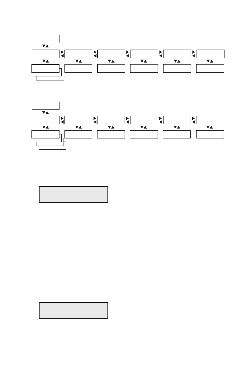
PARITY:
BOOTP
PARITY:
DHCP
PARITY:
MANUAL
SETUP:
NETWORK
NETWORK:
IP SELECTION
NETWORK:
IP ADDRESS
NETWORK:
NETMASK
NETWORK:
DEFAULT ROUTER
NETWORK:
NAMESERVER
IP SELECTION:
DHCP+BOOTP
IP ADDRESS:
192.168.1.79
NETMASK:
255.255.255.0
DEFAULT ROUTER:
192.168.1.1
NAMESERVER:
192.168.1.7
NETWORK:
MAC ADDRESS
MAC ADDRESS:
00104017b80e
Read-only Read-only Read-only Read-only Read-only
These menus will only be displayed when an optional EasyLAN interface board is installed.
PARITY:
DHCP+BOOTP
PARITY:
BOOTP
PARITY:
DHCP
SETUP:
NETWORK
NETWORK:
IP SELECTION
NETWORK:
IP ADDRESS
NETWORK:
NETMASK
NETWORK:
DEFAULT ROUTER
NETWORK:
NAMESERVER
IP SELECTION:
MANUAL
IP ADDRESS:
0.0.0.0
NETMASK:
0.0.0.0
DEFAULT ROUTER:
0.0.0.0
NAMESERVER:
0.0.0.0
NETWORK:
MAC ADDRESS
MAC ADDRESS:
00104017b80e
Read-only Read-only Read-only Read-only Read-only
These menus will only be displayed when an optional EasyLAN interface board is installed.
Chapter 5 — Setup in IPL
Example of the network setup when an automatic IP selection method is used.
Example of the network setup when the manual IP selection method is used or when
the network does not have an DHCP or BOOTP server.
4 Press the key. e display shows the default setting:
IP SELECTION:
DHCP+BOOTP
5 Here, you can select the method for assigning the IP address for the
printer as discussed earlier. ere are four options; DHCP+BOOTP,
MANUAL, DHCP, and BOOTP. If you do not use a DHCP or
BOOTP server, you can either set the IP address manually or use the
ARP'n'PING method.
6 Use the or keys to browse through the options. When the desired
option is displayed, press the <Enter> key.
Reading the IP Address
1 After having selected the method for assigning the IP address, the
display shows:
NETWORK:
IP ADDRESS
EasyLAN Wireless Interface Kit Installation Instructions 51

Chapter 5 — Setup in IPL
2 If you have chosen either DHCP+BOOTP, DHCP, or BOOTP, press
the key and you can read the temporary IP address automatically
assigned by the server, for example:
IP ADDRESS:
192.168.1.79
3 After having read the IP address, press the <Enter> key to go on to
Netmask parameter or press the <Setup> key to exit the Setup Mode.
Reading the Netmask, Default Router, and Name Server
ese parameters work in the same way as reading the IP address. In
case of DHCP, BOOTP, or DHCP+BOOTP, these parameters are set
automatically by the server. In case of the ARP’n’PING method, you will
have to set these parameters via the printer’s home page once the network
communication has been established.
Using ARP’n’PING to set an IP Address (Windows)
e ARP’n’PING method is intended for networks that do not have an
DHCP or BOOTP server.
You must have a free IP address, which will be permanently assigned to
the printer. However, it could be changed later from the printer’s home
page once the communication is established.
You must also have the printer’s MAC address. You can get the MAC
address from the Setup Mode as shown above or from the serial number
label on the EasyLAN board.
If the printer is started with DHCP and/or BOOTP, the printer will try
to find an IP address five times before it considers it a failure. is takes
about 2 minutes during which you cannot start using the ARP’n’PING
method.
e following instructions apply to Windows 2000, but similar methods
can be used on other operating systems, both in Windows and in Unix.
In Windows, the groups of digits in the MAC address are separated by
hyphens (-), and in Unix by colons (:).
52 EasyLAN Wireless Interface Kit Installation Instructions

Chapter 5 — Setup in IPL
To set an IP address with ARP ‘n’ Ping
On the task bar of the host, choose Start > Accessories > Command
1
Prompt.
In the Command Prompt, type:
2
arp -s <desired IP address><printer MAC-address>
While still using the Command Prompt, use ping to make the printer
3
set the IP address by typing:
ping <IP address>
Exit the Command Prompt.
4
EasyLAN Wireless Interface Kit Installation Instructions 53

Chapter 5 — Setup in IPL
Setting Network Parameters in Manual Mode
Note: MANUAL mode is only supported by IPL 2.40 or later.
You can use MANUAL mode to assign a static IP address to the printer.
To assign network values manually, connect the printer to the serial
port on the host PC and open a communications program such as
HyperTerminal. Send this command:
<SI>nn[,m1[,m2]]
where:
n is the IP address, in the format n.n.n.n, where n is a number in the
range 0-255.
,m1 is the subnet mask address written in the same format.
,m2 is the router address written in the same format.
Sending this command places the printer in MANUAL mode
automatically if you specify at least two of the three parameters. If you
specify only one parameter, such as the IP address, you need to place the
printer in MANUAL mode via the printer's keyboard before you send
the command. Otherwise, the command will have no effect.
You can confirm the IP address by sending the upload configuration
parameters command.
Examples:
<STX><SI>n192.168.235.86,255.255.254.0,192.168.234.
1<ETX>
Sets the IP address to 192.168.235.86, the subnet mask to
255.255.254.0, and the router to 192.168.234.1.
<STX><SI>n192.168.235.86<ETX>
Sets the IP address to 192.168.235.86 and uses the default subnet mask
and router settings. You need to place the printer in MANUAL mode via
the printer's keyboard before you send this command.
54 EasyLAN Wireless Interface Kit Installation Instructions

Accessing the Printer’s
6
Home Page
is chapter describes how to access the printer’s
home page in order to determine that the network
communication works properly.
EasyLAN Wireless Interface Kit Installation Instructions 55
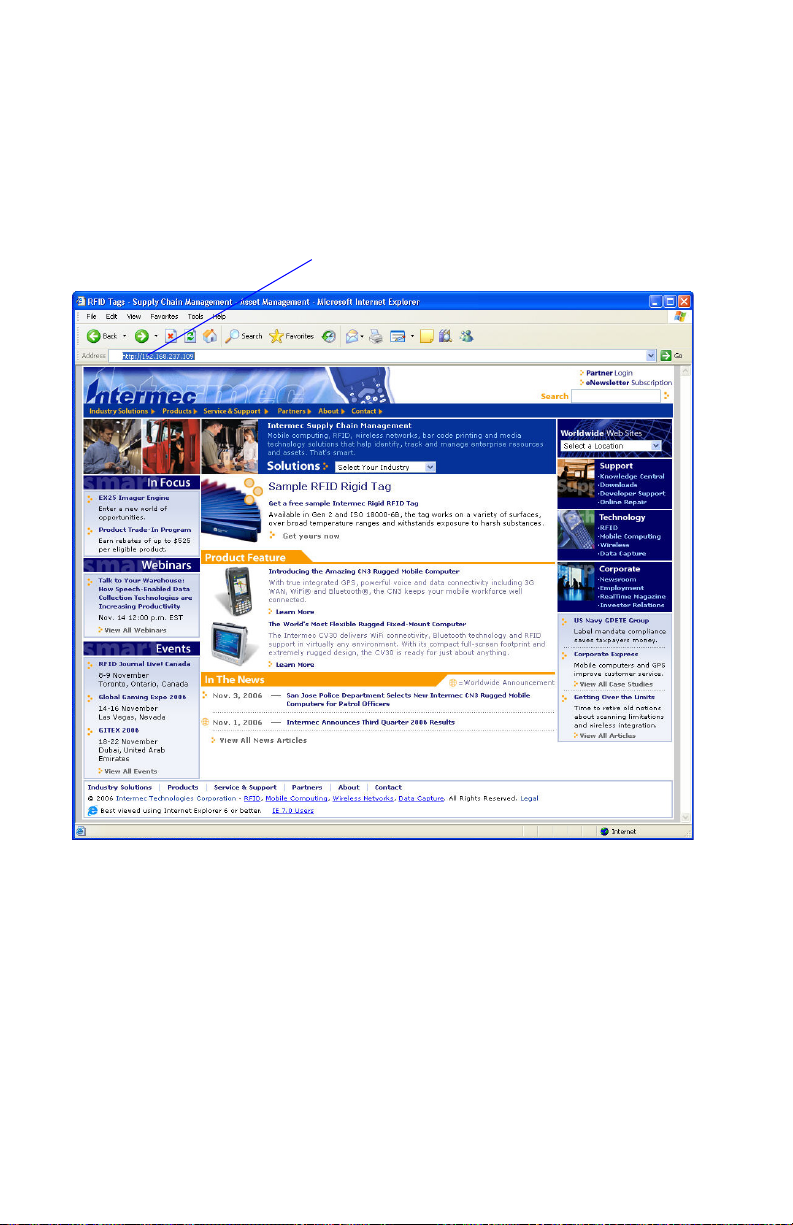
Chapter 6 — Accessing the Printer’s Home Page
Using the Web Browser
Start your web browser (in this example Microsoft Internet Explorer)
and enter the printer’s IP address in the Address field (for example,
http://192.168.237.109).
Enter IP Address
Use your web browser to access the printer’s home page
56 EasyLAN Wireless Interface Kit Installation Instructions

Chapter 6 — Accessing the Printer’s Home Page
e printer’s home page will appear:
The EasyCoder PM4i Home Page
From the printer’s home page, you can perform a large number of tasks,
including changing or setting the IP address, subnet mask, default router,
and name server and changing some of the wireless communication
parameters. Please refer to the EasyLAN User's Guide on the CD included
with the EasyLAN Wireless Interface Kit.
EasyLAN Wireless Interface Kit Installation Instructions 57

Chapter 6 — Accessing the Printer’s Home Page
58 EasyLAN Wireless Interface Kit Installation Instructions


Worldwide Headquarters
6001 36th Avenue West
Everett, Washington 98203
U.S.A.
tel 425.348.2600
fax 425.355.9551
www.intermec.com
EasyLAN Wireless Interface Kit Installation Instructions
*1-960610-04*
P/N 1-960610-04
 Loading...