

Page 1
NX-480 Wireless
Motion Sensor
Document Number: 466-1479 Rev. D
May 1998
60-639
Installation
Instructions
Product Summary
A motion sensor (passive-infrared or PIR) detects
movement within a specific area by sensing the infrared energy emitted from a body as it moves across the
sensor’s field of view, causing a temperature change in
the sensor’s zones. When this motion is detected, the
sensor transmits an alarm signal to the control panel.
Use motion sensors to protect locations where door/
window sensors are impractical or not needed. For
example, use a motion sensor to protect large areas or
open floor plans. Motion sensors also provide backup
protection for door/window sensors.
The NX-480 Wireless Motion Sensor includes the following features:
■ 35 feet by 40 feet coverage area for standard and
animal- alley lenses
■ Masking kit provided to block portions of cover-
age area
■ 3-minute transmitter lockout time after an alarm
that helps extend battery life
■ Cover-activated tamper (optional wall-activated
tamper is included)
■ Supervisory signal transmitted every 64 minutes
to the control panel
■ Sensor low battery reports (trouble) to the control
panel
■ Field-selectable sensitivity options
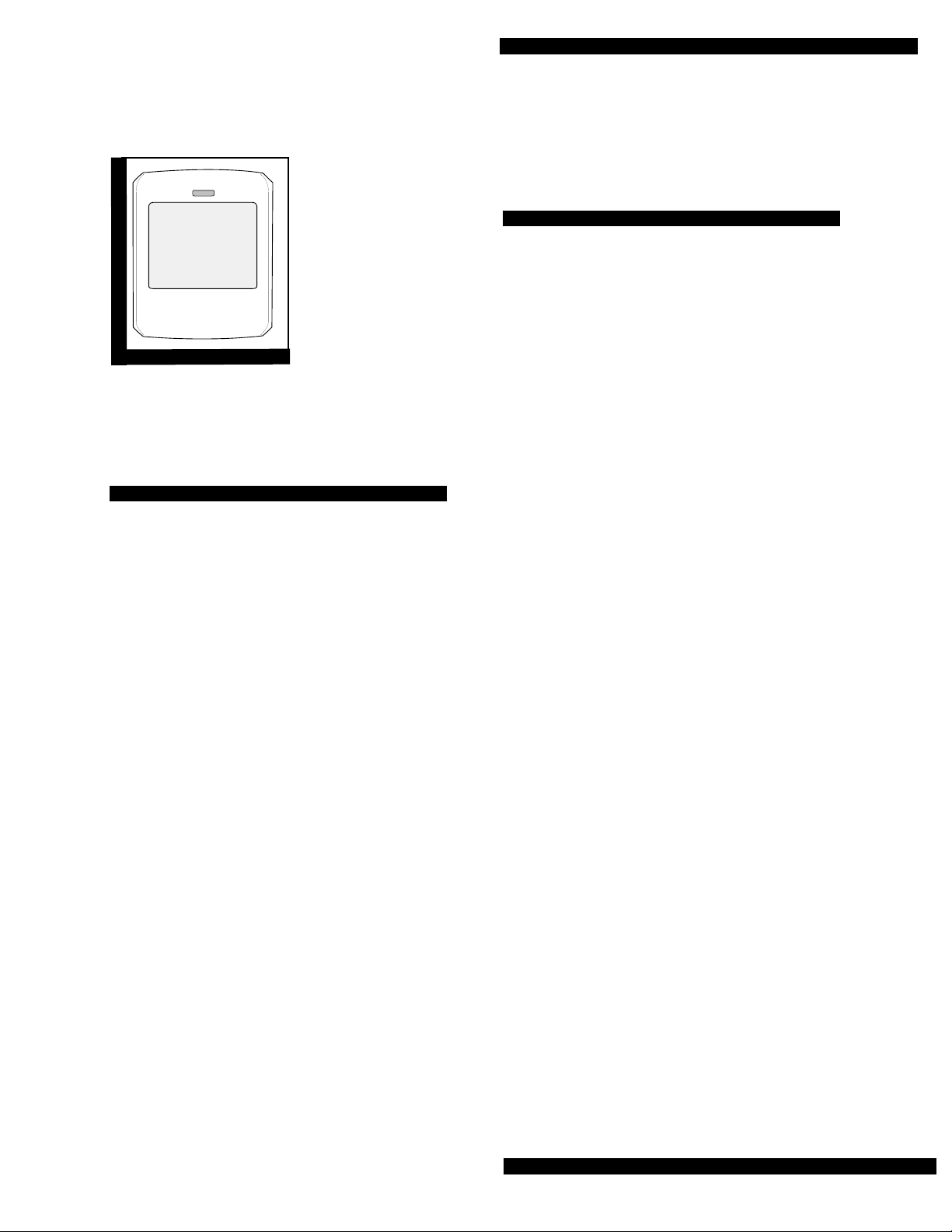
NX-480 Wireless Motion Sensor
Installation Guidelines
Motion sensors are ideal whenever it is not practical to
install Door/Window sensors on every opening. Large
areas in an open floor plan, downstairs family rooms,
and hallways are candidates for motion sensors.
Motion sensors are not suitable for rooms where pets
can enter.
Use the following guidelines for installing motion sensors.
■ If possible, locate sensors within 100 feet of the
panel. While a transmitter may have a range of
500 feet or more out in the open, the environment
at the installation site can have a significant effect
on transmitter range. Sometimes a change in sensor location can help overcome adverse wireless
conditions.
■ Mount the motion sensor on an insulated, outside
wall facing in.
■ Mount the motion sensor on a rigid surface which
is free from vibrations.
■ Position the sensor so it faces a solid reference
point, like a wall.
■ Do not aim the sensor at windows, fireplaces, air
conditioners, area heaters, forced air heating
vents, or place it in direct sunlight. Sudden
changes in temperature may trigger a false alarm
from these devices.
■ Do not mount the sensor near duct work or other
large metallic surfaces which may affect the RF
signals (see RF Testing). Actual acceptable transmitter range should be verified for each installation.
■ Mount the sensor permanently on a flat wall or in
a corner. Do not set it on a shelf.
■ Windows should be closed in any area which has
an armed motion sensor.
■ A pet will trigger a motion sensor. See Animal
Alley lens guidelines to use a motion sensor when
pets are present.
■ Position the sensor to protect an area where an
intruder would be most likely to walk across the
detection pattern (see Figure 1).
Page 1
Page 2
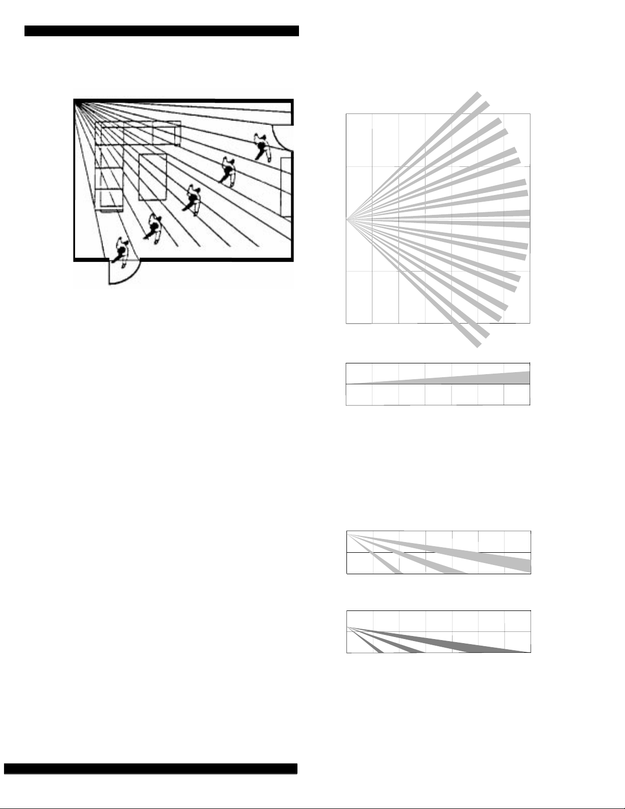
NX-480 Wireless Motion Sensor
Person walking across detection path
8362G04B.DS4
Figure 1. Overhead (Bird’s Eye View) Detection Path
■ For best coverage, mount the sensor from 5 to 8
feet high in the corner of the area you want to
protect. See the Animal Alley lens guidelines for
mounting the Animal Alley lens. Higher mounting provides better range (up to 35 feet), and
lower mounting provides better protection close
to the motion sensor (see Figures 2 and 3).
Animal Alley Lens Guidelines
The animal alley lens provides protection in installations where pets move about freely.
■ Allowed mounting height is between 3 and 5 feet.
■ Position the sensor to have a clear line of sight
across the protected room.
■ For best results, install the sensor higher than the
highest point that the pet might reach in the
detection area.
■ If the detection area contains furniture or other
objects upon which the pet could climb or jump,
either remove these objects, mount the PIR a safe
distance above these objects, or mask these areas.
TOP VIEW
SIDE VIEW
11 m
35 ft
11 ft
2.4 m
1.2 m
0 m
35 ft
8362G07A.DS4
6 m
3 m
0 m
3 m
6 m
0 ft
0 ft
0 ft
0 ft
0 ft
ft
ft
ft
0 m
0 ft
0 m
0 ft
VERTICAL TILT OF 12 DEGREES
Figure 2. Top Graph Shows Both Standard & Animal
Alley Lens Coverage Area. Lower Graph shows Side
View Coverage Area Using the Animal Alley Lens
SIDE VIEWS (STANDARD LENS)
0 m
ft
ft
ft
0 ft
7 1/2 FOOT MOUNTING HEIGHT
11 ft
35 ft
2.4 m
1.2 m
0 m
Page 2
8 ft
4 ft
0 ft
0 m
0 ft
5 FOOT MOUNTING HEIGHT
11 ft
35 ft
8362G09A.DS4
Figure 3. Side Views Show the Differences in the
Coverage Area when using the standard lens
mounted at Different Heights.
2.4 m
1.2 m
0 m
Page 3

Mounting the Sensor
The sensor can be flush-mounted, incline-mounted, or
corner-mounted depending on the application (see
Figure 4).
FLUSH MOUNT
CORNER MOUNT
INCLINED MOUNT
USE WITH
ANIMAL ALLEY LENS
WALL
TAMPER
KNOCKOUT
USE WITH
STANDARD LENS
Figure 5. PIR Mounting Plate Knockouts
NX-480 Wireless Motion Sensor
8362G01B.DS4
8362G03A.DS4
Figure 4. Wall Mount Options: use the inclined
position for surface or corner mounting with the
standard lens. Use the flush position for surface or
corner mounting with the animal alley lens.
Use the following procedure to mount the sensor.
1. Remove the mounting plate by depressing the
button on the top of the sensor body. With the
opposite hand pull the mounting plate away from
the body of the sensor.
2. Punch out the mounting holes that best fit your
application. See Figure 4 for wall mount options.
See also Figure 5 to determine which knockouts to
use when mounting the motion sensor. Use the
lower-side holes for corner mounting, or the
lower-back holes for surface mounting with the
standard lens.
For applications without pets, use the lower
mounting holes. For applications with pets, use
the upper mounting holes and the animal alley
lens.
3. If you desire wall-tamper functionality, remove
the wall-tamper knockout (see Figure 5).
Note: The wall-tamper switch cannot b e used when the
sensor is swivel or corner mounted.
4. Mark the location of the required holes on the
mounting surface.
5. Use wall anchors and screws to secure into
place.Attach the sensor to the mounting plate.
Lens Replacement:
To change the lens, first remove the sensor from
1.
its mounting plate by depressing the button on
the top of the sensor.
2. Remove the cover by depressing the two tabs on
the top and the one tab on the bottom of the sensor body and sliding the cover off (see Figure 7).
3. Remove the installed lens by gently placing pres-
sure on the lens from the outside of the lens.
4. Replace with the appropriate lens by aligning its
notches with the appropriate tabs in the cover.
5. Install the new lens with the smooth side facing
out and the grooved side facing in.
6. Replace the cover and then replace the sensor in
its mounting plate.
Setting the Sensitivity
The PIR is set to standard sensitivity at the factory.
This sensitivity is preferred for most applications and
provides the best immunity to false alarms.
CAUTION: High sensitivity should only be used
in extremely quiet environments
where thermal transients are not
expected.
Page 3
Page 4

NX-480 Wireless Motion Sensor
1. Locate the sensitivity pins by first removing the
mounting plate and the sensor cover as described
in steps 1 and 2 of Lens Replacement process.
STANDARD
HIGH
Figure 6. Sensitivity Pins Locations
8362G06A.DS4
2. Locate the sensitivity pins under the battery on
the right side of the PIR when looking at the front
of the PIR.
3. The sensor is set to standard sensitivity at the fac-
tory. To change this to high sensitivity move the
shorting jumper to the pair of pins that are closer
to the top of the PIR (see Figure 6)
Note: When the walk test mode has ended, an alarm
can be transmitted only after 3 minutes have
passed since the previous alarm. This 3 minute
lockout time reduces unnecessary RF transmissions in high traffic areas thereby extending battery life.
Environment Testing
Turn on all heating or air conditioning sources which
would normally be active during the protection
period. Stand away from the sensor and outside the
coverage pattern and watch for alarms.
Coverage Masking
After walk-testing and environment testing are completed, apply masking labels to the sensor’s lens to
block detection of desired areas. The masking labels
provided are cut to match the corresponding lens segments.
1. Determine which detection zone/lens segment
needs a masking label.
2. Peel the desired mask label from its backing and
apply to the inside of the lens segment to be
blocked.
Note: If the shorting jumper is not used or placed incor-
rectly, the sensor defaults to standard sensitivity.
4. Walk test the PIR to verify the sensitivity.
Walk-Testing
Walk- testing should be done to determine the sensor’s actual coverage area. The edge of the coverage
pattern is determined by the first flash of the LED.
This may change slightly depending upon the sensitivity setting. Walk test the unit from both directions
to determine the pattern boundaries.
1. Removing the sensor body from the mounted
mounting plate and then remounting the body to
activate the 60-second walk test mode.
2. Walk across the coverage pattern to determine the
coverage area, indicated by LED activation. Each
activation extends the walk test mode for an additional 60 seconds.
After the walk test mode has expired, the LED will not
activate when motion is detected.
Note: Excessive use of the walk test mode may reduce
battery life. Use only for initial setup and maintenance testing.
Programming
For complete programming instructions, refer to the
NX-Series Receiver Modules Installation Instructions.
Maintenance
At least once a year, the range and coverage should be
verified for proper operation. The end user should be
instructed to put the sensor in walk test mode and
walk through the far end of the coverage pattern to
verify proper detection.
Replacing Batteries
When battery replacement is necessary, observe
proper polarity (as shown in the battery compartment)
when installing the new battery, or the sensor may be
damaged. Be sure to note that as you look at the battery compartment, on the left side the positive side is
down and on the right side the positive end is up.
When the battery is replaced, wait at least 3 minutes
after installing the battery before activating the walk
test mode. See Figure 7 for battery locations.
Page 4
Page 5

PWB
COVER
MOUNTING
PLATE
TABS
PIR
COVER
SENSOR
BODY
TAMPER
SWITCH
LENS
8362G02A.DS4
NX-480 Wireless Motion Sensor
To relocate a sensor:
1. Test the sensor a few inches from the original
position.
2. Increase the distance from the original position
and retest until an acceptable location is found.
3. Mount the sensor in the new location.
4. If no location is acceptable, replace the sensor.
To replace a sensor:
1. Test a known good sensor at the same location.
2. If the system does not respond, avoid mounting a
sensor at that location.
3. If the replacement sensor functions, return the
problem sensor for repair or replacement.
Specifications
Figure 7. PIR Components, Battery Locations, &
Tamper Switch
Final Testing
Final testing should be done to verify radio signal
integrity and confirm control panel programming and
response. The actual transmitter range can be determined by performing a sensor test as follows:
1. After the sensor has been mounted, remove it
from its mounting plate to activate the walk test
mode.
2. Replace the sensor in its mounting plate.
3. Place the control panel in test mode. Move across
the detection pattern until the sensor’s LED turns
on. STOP your motion.
4. Listen for the appropriate system response. If the
system does not respond, proceed to the “Troubleshooting “section.
Troubleshooting
Frequency: 319.5 MHz. (NX-480)
433 MHz. (60-639-43-EUR)
Power source: 2 AA alkaline batteries
Typical battery life: 3 - 4 years (not verified by U.L.)
Operating temperature range: 32° to 120° F
Dimensions: L = 2.875” X W = 2.375” X H = 1.875”
Notices
These devices comply with part 15 of the FCC rules. Operation is subject to the following two conditions:
1. These devices may not cause harmful interference.
2. These devices must accept any interference received, including
interference that may cause undesire d oper ation.
Changes or modifications not expressly approved by Interactive Technologies, Inc. can void the users’ authority to operate the equipment.
Use the following guidelines if the system does not
respond correctly when the sensor is activated.
■ Check programming and re-program sensor into
panel if necessary.
■ Use an RF Sniffer (NX-468) test tool to verify that
the sensor is transmitting. Constant beeps from
the RF Sniffer indicate a runaway (faulty) sensor.
Replace the sensor.
■ Move the sensor to another location and test for
correct response.
Page 5
Page 6

NX-480 Wireless Motion Sensor
Page 6
Caddx Controls, Inc. 1420 North Main Street Gladewater, Texas 75647
Toll Free: 1-800-727-2339 FAX: (903) 845-6811
Caddx is a registered trademark of Caddx Controls, Inc.
 Loading...