

Page 1
1HWZ RU ;1 ; (6HULHV
5HFHLY HU0RGXOHV
ITI Part No. 60-904
Document Number: 466-1427 Rev. F
July 2001
Product Summary
The NX-E Series Receiver Modules (8-zone NX-408E, 16zone NX-416E, and 48-zone NX-448E) add wireless capabilities to the Caddx
®
NetworX NX-4, NX-6, NX-8, and
NX-8E control panels. Adding a receiver module makes
these control panels compatible with NX wireless transmitters and keychain touchpads (keyfobs).
The receiver modules mount inside the control panel cabinet and require just three wire connections for power and
data communications to the motherboard.
Installation Guidelines
Use the following guidelines when installing receiver modules:
❑ Leave at least 10" above the control panel for the mod-
ule’s antennas.
❑ Avoid areas that are likely to expose the module to
moisture.
❑ Avoid areas with excessive metal or electrical wiring,
including furnace and utility rooms.
Installing the Receiver Module
The following steps describe mounting the circuit board
edge guide standoff, securin g the module to the ca binet, and
inserting the antennas.
9740G15A.DS4
Installation Instructions
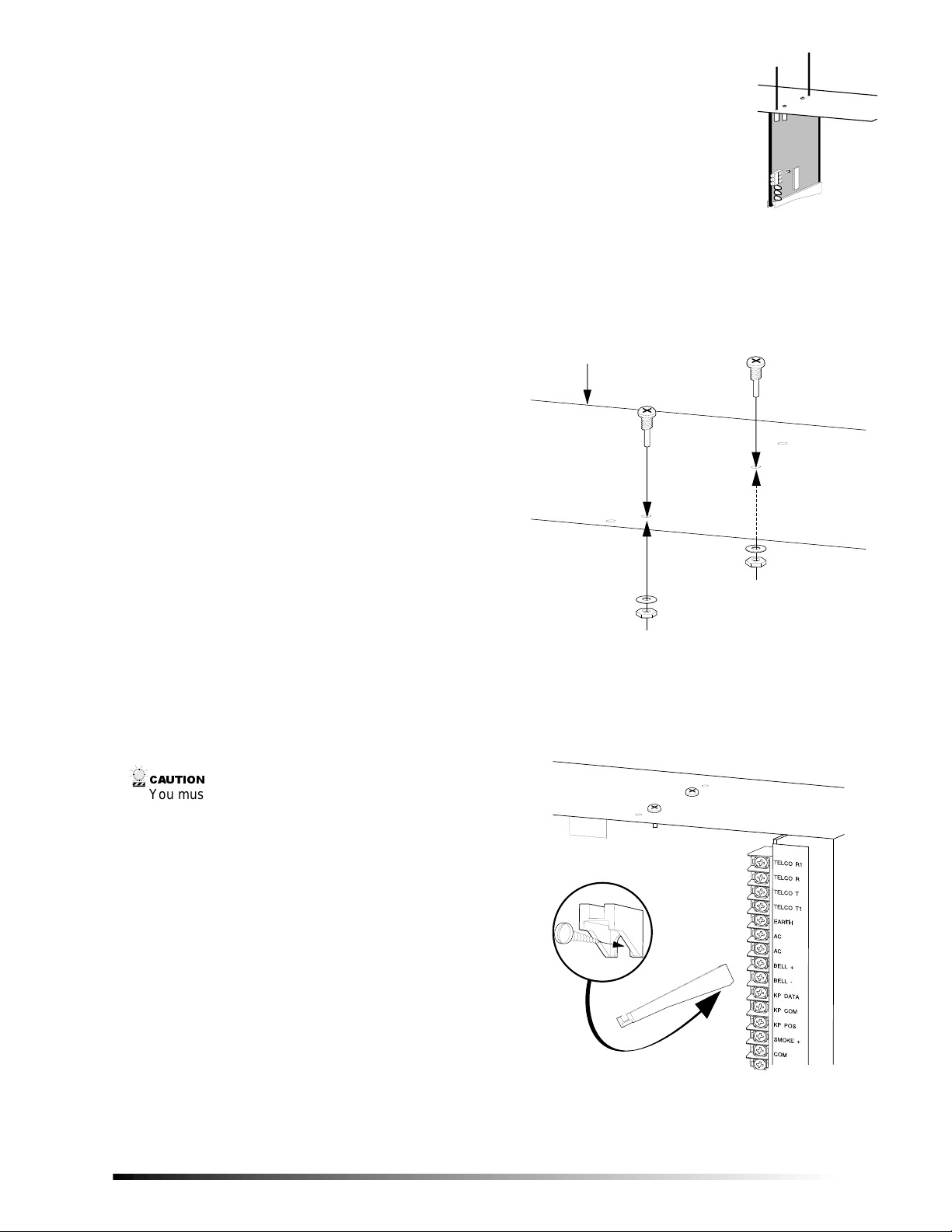
1. After mounting the control panel cabinet, install the
ground plane screws, washers, and nuts (included) in
the holes on top of the cabinet (see Figure 1).
TOP OF
ENCLOSURE
9740G05A.DS4
Figure 1. Installin g the Ground Plane Screws, Wash-
ers, and Nuts
2. Install the circuit board edge guide standoff in the
lower mounting hole, in either of the two spaces
located just to the left of the motherboard (see Figure
2). Do not tighten the standoff at this time.
&$87,21
You must be free of static electricity before handling
circuit boards. Touch a bare metal surface or wear a
grounding strap to discharge yourself.
9740G08A.DS4
Figure 2. Installing the Circuit Board Edge Guide
Standoff
1
Page 2
Installation Guidelines
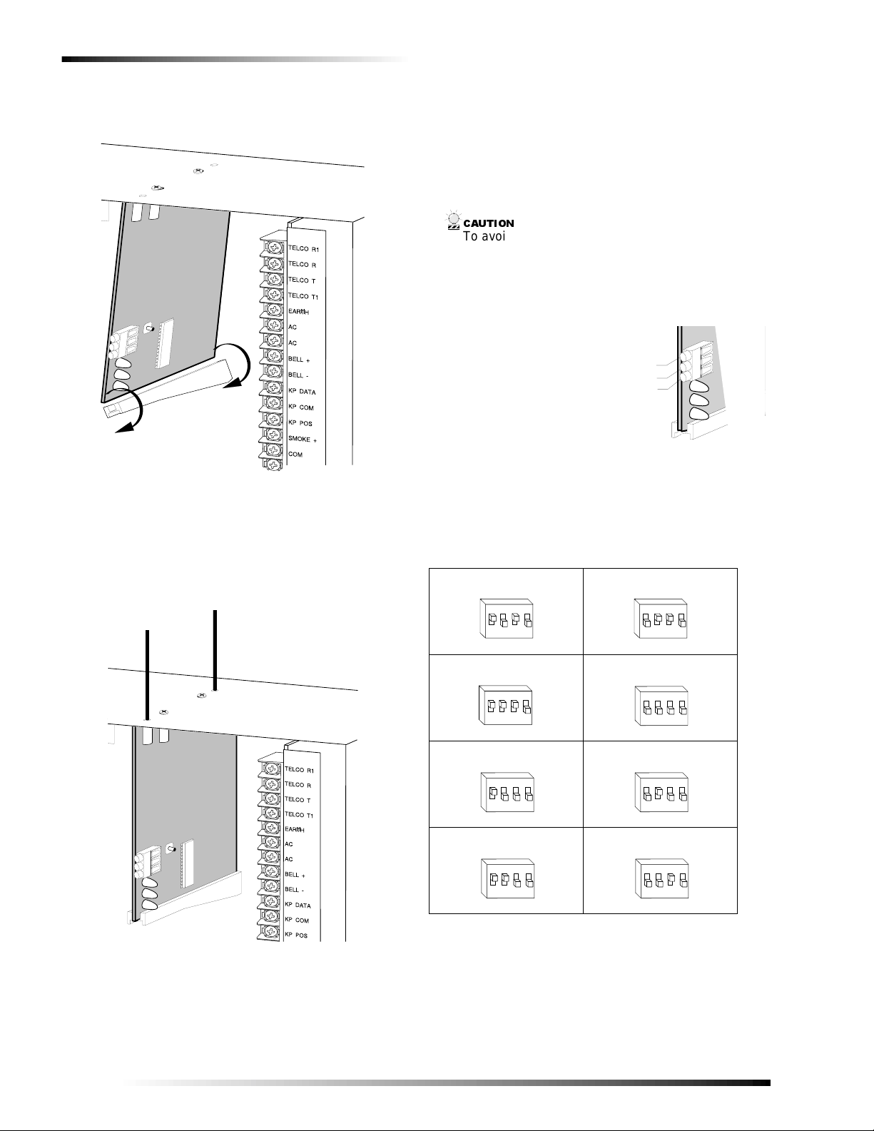
3. Install the module into the cabinet by turning the standoff sideways, then sli de the mo dul e up onto t he g rou nd
plane screw posts (see Figure 3).
9740G04A.DS4
Figure 3. Installing the Module into the Cabinet
4. Turn the standoff so the slot is facing up, insert the
back corner of the module into the standoff slot, then
press up at the front of the standoff and tighten the
standoff screw.
5. Insert the antennas through the holes on top o f the cabinet and into the module antenna sockets (see Figure 4).
Wiring, Module Number DIP Switch
Settings, and Power Up
The following steps describe wiring the module to the control panel, setting the module number DIP switches, and
powering up the control panel.
1. Remove power (if applied) from the control panel.
&$87,21
To avoid possible equipment damage or personal
injury, remove power from the control panel before
making any wiring connections to the module.
2. Connect the module power and data terminals to the
control panel power and data te rminal s us i ng 2 2-gau ge
or larger, stranded wire (see Figure 5).
P O W E R + ( T O P A N E L A U X P W R + )
Figure 5. Wiring the Module Power and Data Terminals
3. Set the module DIP switches to the desired module
number (see Table 1).
Table 1. Receiver Module Number Settings
Module Number 32 Module Number 33
O N
1 2
G N D ( T O P A N E L C O M )
D A T A ( T O P A N E L K P D A T A )
9 7 4 0 G 1 4 B . D S 4
to the Panel Power and Data Terminals
E D G O N
43
E D G
43
1 2
Module Number 34 Module Number 35
O N
E D G
43
1 2
ON
EDG
43
1 2
Module Number 36 Module Number 37
O N
E D G O N
43
1 2
E D G
43
1 2
Module Number 38 Module Number 39
O N
E D G O N
43
1 2
9740G10A.DS4
Figure 4. Inserting the Antennas
2
E D G
43
1 2
Page 3

Programming
4. Apply power to the control panel. The middle (red )
LED on the module should start blinking. Table 2
describes the module’s statu s based on LED conditi ons.
Table 2. Module Status Conditions
LED Module Status
Red-blinking
Red-off
Yellow-blinking
Yellow-off
Note
The red LED at the bottom of the module may emit a dim
glow but is not used as an indicat or and can be ignored.
Normal data communication with
the control panel.
No data communication with
control panel. Check wiring and
power source.
Receiving radio signals from
wireless sensors.
No radio signals currently being
received.
Programming
Special Settings for Door/Window Transmitters
Use the following guidelines when setting features 4 and 5
for door/window transmitters and wireless smoke detectors.
❑ Feature 4—Input Option 1
For door/window transmitters, turn on thi s feature to
disable the transmitter’s internal reed switches.
For wireless smoke detectors with tamper switches, turn on
this feature to enable the tamper feature.
Note
Feature 4—Input Option 1, must be off (disabled) when
using wireless smoke detectors without tamper switches.
❑ Feature 5—Input Option 2
For door/window transmitters that use a normally open
external contact, leave this feature off (N/O).
For door/window transmitters that use a normally
closed external contact, turn this feature on (N/C).
Light and Star Buttons on 4-Button Keyfobs
When using 4-button keyfobs, turning on Input Option 1
(feature 4) changes the light button to Keyfob Function 1.
Turning on Input Option 2 (feature 5) changes the star button to Keyfob Function 2. These functions can be used to
control relays, outputs, or X-10 devices.
This section describes the following programming steps:
❑ Determine Programming Settings—provi des tables to
record wireless transmitter and partition settings .
❑ Enroll the Module—sets up the module to be super-
vised by the control panel.
❑ Program the Module—puts the module into program so
you can program zone bank settings, transmitters, and
enter the settings for transmitters and partitions.
Determine Programming Settings
When programming wireless transmitters into the mod ule,
there are various options and partitions you can set for each
transmitter. These settings appear in segments of each programming location.
Use “T able 3: Module Programming Settings” on pages 3 7 to record zone assignments and settings. Be sure to circle
the module type in the location column to help identify
where each zone resides; RM = receiver module, HE =
hardwire expander, P = panel. This gives you all the programming information in one place and helps speed up the
programming process.
Zone Locations 1 - 192
Zone locations 1 - 192 are not numbered in Table 3 since
these locations vary depending on location 194—Receiver
Zone Bank Setting (see page 8).
For example, if location 194 is set to 3, the first available
location is 25. The total number of available locations is
dependant on the zone limits for both the pan el and receiver.
Note
The default settings shown fo r Se gm ents 1 and 2 in the
first zone location apply to all zone locations.
Table 3. Module Programming Settings
Location Segment 1 Segment 2
0
Transmitter
to be programmed)
Zone _____
Assigned to
module
#_____.
RM HE P
None None
1 - Enable senso r ❏
(default = off)
2 - Supervised ❏
(default = on)
3 - Fire supervisi on ❏
(default = off)
4 - Input option 1 ❏
(default = off)
5 - Input option 2 ❏
(default = off)
6 - 8 Not used
Partition 1 keyfob ❏
(default = on)
Partition 2 keyfob ❏
(default = off)
Partition 3 keyfob ❏
(default = off)
Partition 4 keyfob ❏
(default = off)
Partition 5 keyfob ❏
(default = off)
Partition 6 keyfob ❏
(default = off)
Partition 7 keyfob ❏
(default = off)
Partition 8 keyfob ❏
(default = off)
3
Page 4

Programming
Table 3. Module Programming Settings
(Continued)
Location Segment 1 Segment 2
Zone _____
Assigned to
module
#_____.
RM HE P
Zone _____
Assigned to
module
#_____.
RM HE P
Zone _____
Assigned to
module
#_____.
RM HE P
1 - Enable sensor ❏
2 - Supervised ❏
3 - Fire supervision ❏
4 - Input option 1 ❏
5 - Input option 2 ❏
6 - 8 Not used
1 - Enable sensor ❏
2 - Supervised ❏
3 - Fire supervision ❏
4 - Input option 1 ❏
5 - Input option 2 ❏
6 - 8 Not used
1 - Enable sensor ❏
2 - Supervised ❏
3 - Fire supervision ❏
4 - Input option 1 ❏
5 - Input option 2 ❏
6 - 8 Not used
Partition 1 keyfob ❏
Partition 2 keyfob ❏
Partition 3 keyfob ❏
Partition 4 keyfob ❏
Partition 5 keyfob ❏
Partition 6 keyfob ❏
Partition 7 keyfob ❏
Partition 8 keyfob ❏
Partition 1 keyfob ❏
Partition 2 keyfob ❏
Partition 3 keyfob ❏
Partition 4 keyfob ❏
Partition 5 keyfob ❏
Partition 6 keyfob ❏
Partition 7 keyfob ❏
Partition 8 keyfob ❏
Partition 1 keyfob ❏
Partition 2 keyfob ❏
Partition 3 keyfob ❏
Partition 4 keyfob ❏
Partition 5 keyfob ❏
Partition 6 keyfob ❏
Partition 7 keyfob ❏
Partition 8 keyfob ❏
Table 3. Module Programming Settings
(Continued)
Location Segment 1 Segment 2
Zone _____
Assigned to
module
#_____.
RM HE P
Zone _____
Assigned to
module
#_____.
RM HE P
Zone _____
Assigned to
module
#_____.
RM HE P
1 - Enable senso r ❏
2 - Supervised ❏
3 - Fire supervisi on ❏
4 - Input option 1 ❏
5 - Input option 2 ❏
6 - 8 Not used
1 - Enable senso r ❏
2 - Supervised ❏
3 - Fire supervisi on ❏
4 - Input option 1 ❏
5 - Input option 2 ❏
6 - 8 Not used
1 - Enable senso r ❏
2 - Supervised ❏
3 - Fire supervisi on ❏
4 - Input option 1 ❏
5 - Input option 2 ❏
6 - 8 Not used
Partition 1 keyfob ❏
Partition 2 keyfob ❏
Partition 3 keyfob ❏
Partition 4 keyfob ❏
Partition 5 keyfob ❏
Partition 6 keyfob ❏
Partition 7 keyfob ❏
Partition 8 keyfob ❏
Partition 1 keyfob ❏
Partition 2 keyfob ❏
Partition 3 keyfob ❏
Partition 4 keyfob ❏
Partition 5 keyfob ❏
Partition 6 keyfob ❏
Partition 7 keyfob ❏
Partition 8 keyfob ❏
Partition 1 keyfob ❏
Partition 2 keyfob ❏
Partition 3 keyfob ❏
Partition 4 keyfob ❏
Partition 5 keyfob ❏
Partition 6 keyfob ❏
Partition 7 keyfob ❏
Partition 8 keyfob ❏
Zone _____
Assigned to
module
#_____.
RM HE P
Zone _____
Assigned to
module
#_____.
RM HE P
Zone _____
Assigned to
module
#_____.
RM HE P
1 - Enable sensor ❏
2 - Supervised ❏
3 - Fire supervision ❏
4 - Input option 1 ❏
5 - Input option 2 ❏
6 - 8 Not used
1 - Enable sensor ❏
2 - Supervised ❏
3 - Fire supervision ❏
4 - Input option 1 ❏
5 - Input option 2 ❏
6 - 8 Not used
1 - Enable sensor ❏
2 - Supervised ❏
3 - Fire supervision ❏
4 - Input option 1 ❏
5 - Input option 2 ❏
6 - 8 Not used
Partition 1 keyfob ❏
Partition 2 keyfob ❏
Partition 3 keyfob ❏
Partition 4 keyfob ❏
Partition 5 keyfob ❏
Partition 6 keyfob ❏
Partition 7 keyfob ❏
Partition 8 keyfob ❏
Partition 1 keyfob ❏
Partition 2 keyfob ❏
Partition 3 keyfob ❏
Partition 4 keyfob ❏
Partition 5 keyfob ❏
Partition 6 keyfob ❏
Partition 7 keyfob ❏
Partition 8 keyfob ❏
Partition 1 keyfob ❏
Partition 2 keyfob ❏
Partition 3 keyfob ❏
Partition 4 keyfob ❏
Partition 5 keyfob ❏
Partition 6 keyfob ❏
Partition 7 keyfob ❏
Partition 8 keyfob ❏
Zone _____
Assigned to
module
#_____.
RM HE P
Zone _____
Assigned to
module
#_____.
RM HE P
Zone _____
Assigned to
module
#_____.
RM HE P
1 - Enable senso r ❏
2 - Supervised ❏
3 - Fire supervisi on ❏
4 - Input option 1 ❏
5 - Input option 2 ❏
6 - 8 Not used
1 - Enable senso r ❏
2 - Supervised ❏
3 - Fire supervisi on ❏
4 - Input option 1 ❏
5 - Input option 2 ❏
6 - 8 Not used
1 - Enable senso r ❏
2 - Supervised ❏
3 - Fire supervisi on ❏
4 - Input option 1 ❏
5 - Input option 2 ❏
6 - 8 Not used
Partition 1 keyfob ❏
Partition 2 keyfob ❏
Partition 3 keyfob ❏
Partition 4 keyfob ❏
Partition 5 keyfob ❏
Partition 6 keyfob ❏
Partition 7 keyfob ❏
Partition 8 keyfob ❏
Partition 1 keyfob ❏
Partition 2 keyfob ❏
Partition 3 keyfob ❏
Partition 4 keyfob ❏
Partition 5 keyfob ❏
Partition 6 keyfob ❏
Partition 7 keyfob ❏
Partition 8 keyfob ❏
Partition 1 keyfob ❏
Partition 2 keyfob ❏
Partition 3 keyfob ❏
Partition 4 keyfob ❏
Partition 5 keyfob ❏
Partition 6 keyfob ❏
Partition 7 keyfob ❏
Partition 8 keyfob ❏
4
Page 5

Programming
Table 3. Module Programming Settings
(Continued)
Location Segment 1 Segment 2
Zone _____
Assigned to
module
#_____.
RM HE P
Zone _____
Assigned to
module
#_____.
RM HE P
Zone _____
Assigned to
module
#_____.
RM HE P
1 - Enable senso r ❏
2 - Supervised ❏
3 - Fire supervision ❏
4 - Input option 1 ❏
5 - Input option 2 ❏
6 - 8 Not used
1 - Enable senso r ❏
2 - Supervised ❏
3 - Fire supervision ❏
4 - Input option 1 ❏
5 - Input option 2 ❏
6 - 8 Not used
1 - Enable senso r ❏
2 - Supervised ❏
3 - Fire supervision ❏
4 - Input option 1 ❏
5 - Input option 2 ❏
6 - 8 Not used
Partition 1 keyfob ❏
Partition 2 keyfob ❏
Partition 3 keyfob ❏
Partition 4 keyfob ❏
Partition 5 keyfob ❏
Partition 6 keyfob ❏
Partition 7 keyfob ❏
Partition 8 keyfob ❏
Partition 1 keyfob ❏
Partition 2 keyfob ❏
Partition 3 keyfob ❏
Partition 4 keyfob ❏
Partition 5 keyfob ❏
Partition 6 keyfob ❏
Partition 7 keyfob ❏
Partition 8 keyfob ❏
Partition 1 keyfob ❏
Partition 2 keyfob ❏
Partition 3 keyfob ❏
Partition 4 keyfob ❏
Partition 5 keyfob ❏
Partition 6 keyfob ❏
Partition 7 keyfob ❏
Partition 8 keyfob ❏
Table 3. Module Programming Settings
(Continued)
Location Segment 1 Segment 2
Zone _____
Assigned to
module
#_____.
RM HE P
Zone _____
Assigned to
module
#_____.
RM HE P
Zone _____
Assigned to
module
#_____.
RM HE P
1 - Enable senso r ❏
2 - Supervised ❏
3 - Fire supervisi on ❏
4 - Input option 1 ❏
5 - Input option 2 ❏
6 - 8 Not used
1 - Enable senso r ❏
2 - Supervised ❏
3 - Fire supervisi on ❏
4 - Input option 1 ❏
5 - Input option 2 ❏
6 - 8 Not used
1 - Enable senso r ❏
2 - Supervised ❏
3 - Fire supervisi on ❏
4 - Input option 1 ❏
5 - Input option 2 ❏
6 - 8 Not used
Partition 1 keyfob ❏
Partition 2 keyfob ❏
Partition 3 keyfob ❏
Partition 4 keyfob ❏
Partition 5 keyfob ❏
Partition 6 keyfob ❏
Partition 7 keyfob ❏
Partition 8 keyfob ❏
Partition 1 keyfob ❏
Partition 2 keyfob ❏
Partition 3 keyfob ❏
Partition 4 keyfob ❏
Partition 5 keyfob ❏
Partition 6 keyfob ❏
Partition 7 keyfob ❏
Partition 8 keyfob ❏
Partition 1 keyfob ❏
Partition 2 keyfob ❏
Partition 3 keyfob ❏
Partition 4 keyfob ❏
Partition 5 keyfob ❏
Partition 6 keyfob ❏
Partition 7 keyfob ❏
Partition 8 keyfob ❏
Zone _____
Assigned to
module
#_____.
RM HE P
Zone _____
Assigned to
module
#_____.
RM HE P
Zone _____
Assigned to
module
#_____.
RM HE P
1 - Enable senso r ❏
2 - Supervised ❏
3 - Fire supervision ❏
4 - Input option 1 ❏
5 - Input option 2 ❏
6 - 8 Not used
1 - Enable senso r ❏
2 - Supervised ❏
3 - Fire supervision ❏
4 - Input option 1 ❏
5 - Input option 2 ❏
6 - 8 Not used
1 - Enable senso r ❏
2 - Supervised ❏
3 - Fire supervision ❏
4 - Input option 1 ❏
5 - Input option 2 ❏
6 - 8 Not used
Partition 1 keyfob ❏
Partition 2 keyfob ❏
Partition 3 keyfob ❏
Partition 4 keyfob ❏
Partition 5 keyfob ❏
Partition 6 keyfob ❏
Partition 7 keyfob ❏
Partition 8 keyfob ❏
Partition 1 keyfob ❏
Partition 2 keyfob ❏
Partition 3 keyfob ❏
Partition 4 keyfob ❏
Partition 5 keyfob ❏
Partition 6 keyfob ❏
Partition 7 keyfob ❏
Partition 8 keyfob ❏
Partition 1 keyfob ❏
Partition 2 keyfob ❏
Partition 3 keyfob ❏
Partition 4 keyfob ❏
Partition 5 keyfob ❏
Partition 6 keyfob ❏
Partition 7 keyfob ❏
Partition 8 keyfob ❏
Zone _____
Assigned to
module
#_____.
RM HE P
Zone _____
Assigned to
module
#_____.
RM HE P
Zone _____
Assigned to
module
#_____.
RM HE P
1 - Enable senso r ❏
2 - Supervised ❏
3 - Fire supervisi on ❏
4 - Input option 1 ❏
5 - Input option 2 ❏
6 - 8 Not used
1 - Enable senso r ❏
2 - Supervised ❏
3 - Fire supervisi on ❏
4 - Input option 1 ❏
5 - Input option 2 ❏
6 - 8 Not used
1 - Enable senso r ❏
2 - Supervised ❏
3 - Fire supervisi on ❏
4 - Input option 1 ❏
5 - Input option 2 ❏
6 - 8 Not used
Partition 1 keyfob ❏
Partition 2 keyfob ❏
Partition 3 keyfob ❏
Partition 4 keyfob ❏
Partition 5 keyfob ❏
Partition 6 keyfob ❏
Partition 7 keyfob ❏
Partition 8 keyfob ❏
Partition 1 keyfob ❏
Partition 2 keyfob ❏
Partition 3 keyfob ❏
Partition 4 keyfob ❏
Partition 5 keyfob ❏
Partition 6 keyfob ❏
Partition 7 keyfob ❏
Partition 8 keyfob ❏
Partition 1 keyfob ❏
Partition 2 keyfob ❏
Partition 3 keyfob ❏
Partition 4 keyfob ❏
Partition 5 keyfob ❏
Partition 6 keyfob ❏
Partition 7 keyfob ❏
Partition 8 keyfob ❏
5
Page 6

Programming
Table 3. Module Programming Settings
(Continued)
Location Segment 1 Segment 2
Zone _____
Assigned to
module
#_____.
RM HE P
Zone _____
Assigned to
module
#_____.
RM HE P
Zone _____
Assigned to
module
#_____.
RM HE P
1 - Enable sensor ❏
2 - Supervised ❏
3 - Fire supervision ❏
4 - Input option 1 ❏
5 - Input option 2 ❏
6 - 8 Not used
1 - Enable sensor ❏
2 - Supervised ❏
3 - Fire supervision ❏
4 - Input option 1 ❏
5 - Input option 2 ❏
6 - 8 Not used
1 - Enable sensor ❏
2 - Supervised ❏
3 - Fire supervision ❏
4 - Input option 1 ❏
5 - Input option 2 ❏
6 - 8 Not used
Partition 1 keyfob ❏
Partition 2 keyfob ❏
Partition 3 keyfob ❏
Partition 4 keyfob ❏
Partition 5 keyfob ❏
Partition 6 keyfob ❏
Partition 7 keyfob ❏
Partition 8 keyfob ❏
Partition 1 keyfob ❏
Partition 2 keyfob ❏
Partition 3 keyfob ❏
Partition 4 keyfob ❏
Partition 5 keyfob ❏
Partition 6 keyfob ❏
Partition 7 keyfob ❏
Partition 8 keyfob ❏
Partition 1 keyfob ❏
Partition 2 keyfob ❏
Partition 3 keyfob ❏
Partition 4 keyfob ❏
Partition 5 keyfob ❏
Partition 6 keyfob ❏
Partition 7 keyfob ❏
Partition 8 keyfob ❏
Table 3. Module Programming Settings
(Continued)
Location Segment 1 Segment 2
Zone _____
Assigned to
module
#_____.
RM HE P
Zone _____
Assigned to
module
#_____.
RM HE P
Zone _____
Assigned to
module
#_____.
RM HE P
1 - Enable senso r ❏
2 - Supervised ❏
3 - Fire supervisi on ❏
4 - Input option 1 ❏
5 - Input option 2 ❏
6 - 8 Not used
1 - Enable senso r ❏
2 - Supervised ❏
3 - Fire supervisi on ❏
4 - Input option 1 ❏
5 - Input option 2 ❏
6 - 8 Not used
1 - Enable senso r ❏
2 - Supervised ❏
3 - Fire supervisi on ❏
4 - Input option 1 ❏
5 - Input option 2 ❏
6 - 8 Not used
Partition 1 keyfob ❏
Partition 2 keyfob ❏
Partition 3 keyfob ❏
Partition 4 keyfob ❏
Partition 5 keyfob ❏
Partition 6 keyfob ❏
Partition 7 keyfob ❏
Partition 8 keyfob ❏
Partition 1 keyfob ❏
Partition 2 keyfob ❏
Partition 3 keyfob ❏
Partition 4 keyfob ❏
Partition 5 keyfob ❏
Partition 6 keyfob ❏
Partition 7 keyfob ❏
Partition 8 keyfob ❏
Partition 1 keyfob ❏
Partition 2 keyfob ❏
Partition 3 keyfob ❏
Partition 4 keyfob ❏
Partition 5 keyfob ❏
Partition 6 keyfob ❏
Partition 7 keyfob ❏
Partition 8 keyfob ❏
Zone _____
Assigned to
module
#_____.
RM HE P
Zone _____
Assigned to
module
#_____.
RM HE P
Zone _____
Assigned to
module
#_____.
RM HE P
1 - Enable sensor ❏
2 - Supervised ❏
3 - Fire supervision ❏
4 - Input option 1 ❏
5 - Input option 2 ❏
6 - 8 Not used
1 - Enable sensor ❏
2 - Supervised ❏
3 - Fire supervision ❏
4 - Input option 1 ❏
5 - Input option 2 ❏
6 - 8 Not used
1 - Enable sensor ❏
2 - Supervised ❏
3 - Fire supervision ❏
4 - Input option 1 ❏
5 - Input option 2 ❏
6 - 8 Not used
Partition 1 keyfob ❏
Partition 2 keyfob ❏
Partition 3 keyfob ❏
Partition 4 keyfob ❏
Partition 5 keyfob ❏
Partition 6 keyfob ❏
Partition 7 keyfob ❏
Partition 8 keyfob ❏
Partition 1 keyfob ❏
Partition 2 keyfob ❏
Partition 3 keyfob ❏
Partition 4 keyfob ❏
Partition 5 keyfob ❏
Partition 6 keyfob ❏
Partition 7 keyfob ❏
Partition 8 keyfob ❏
Partition 1 keyfob ❏
Partition 2 keyfob ❏
Partition 3 keyfob ❏
Partition 4 keyfob ❏
Partition 5 keyfob ❏
Partition 6 keyfob ❏
Partition 7 keyfob ❏
Partition 8 keyfob ❏
Zone _____
Assigned to
module
#_____.
RM HE P
Zone _____
Assigned to
module
#_____.
RM HE P
Zone _____
Assigned to
module
#_____.
RM HE P
1 - Enable senso r ❏
2 - Supervised ❏
3 - Fire supervisi on ❏
4 - Input option 1 ❏
5 - Input option 2 ❏
6 - 8 Not used
1 - Enable senso r ❏
2 - Supervised ❏
3 - Fire supervisi on ❏
4 - Input option 1 ❏
5 - Input option 2 ❏
6 - 8 Not used
1 - Enable senso r ❏
2 - Supervised ❏
3 - Fire supervisi on ❏
4 - Input option 1 ❏
5 - Input option 2 ❏
6 - 8 Not used
Partition 1 keyfob ❏
Partition 2 keyfob ❏
Partition 3 keyfob ❏
Partition 4 keyfob ❏
Partition 5 keyfob ❏
Partition 6 keyfob ❏
Partition 7 keyfob ❏
Partition 8 keyfob ❏
Partition 1 keyfob ❏
Partition 2 keyfob ❏
Partition 3 keyfob ❏
Partition 4 keyfob ❏
Partition 5 keyfob ❏
Partition 6 keyfob ❏
Partition 7 keyfob ❏
Partition 8 keyfob ❏
Partition 1 keyfob ❏
Partition 2 keyfob ❏
Partition 3 keyfob ❏
Partition 4 keyfob ❏
Partition 5 keyfob ❏
Partition 6 keyfob ❏
Partition 7 keyfob ❏
Partition 8 keyfob ❏
6
Page 7

Programming
Table 3. Module Programming Settings
(Continued)
Location Segment 1 Segment 2
Zone _____
Assigned to
module
#_____.
RM HE P
Zone _____
Assigned to
module
#_____.
RM HE P
Zone _____
Assigned to
module
#_____.
RM HE P
1 - Enable senso r ❏
2 - Supervised ❏
3 - Fire supervision ❏
4 - Input option 1 ❏
5 - Input option 2 ❏
6 - 8 Not used
1 - Enable senso r ❏
2 - Supervised ❏
3 - Fire supervision ❏
4 - Input option 1 ❏
5 - Input option 2 ❏
6 - 8 Not used
1 - Enable senso r ❏
2 - Supervised ❏
3 - Fire supervision ❏
4 - Input option 1 ❏
5 - Input option 2 ❏
6 - 8 Not used
Partition 1 keyfob ❏
Partition 2 keyfob ❏
Partition 3 keyfob ❏
Partition 4 keyfob ❏
Partition 5 keyfob ❏
Partition 6 keyfob ❏
Partition 7 keyfob ❏
Partition 8 keyfob ❏
Partition 1 keyfob ❏
Partition 2 keyfob ❏
Partition 3 keyfob ❏
Partition 4 keyfob ❏
Partition 5 keyfob ❏
Partition 6 keyfob ❏
Partition 7 keyfob ❏
Partition 8 keyfob ❏
Partition 1 keyfob ❏
Partition 2 keyfob ❏
Partition 3 keyfob ❏
Partition 4 keyfob ❏
Partition 5 keyfob ❏
Partition 6 keyfob ❏
Partition 7 keyfob ❏
Partition 8 keyfob ❏
Table 3. Module Programming Settings
(Continued)
Location Segment 1 Segment 2
Zone _____
Assigned to
module
#_____.
RM HE P
Zone _____
Assigned to
module
#_____.
RM HE P
Zone _____
Assigned to
module
#_____.
RM HE P
1 - Enable senso r ❏
2 - Supervised ❏
3 - Fire supervisi on ❏
4 - Input option 1 ❏
5 - Input option 2 ❏
6 - 8 Not used
1 - Enable senso r ❏
2 - Supervised ❏
3 - Fire supervisi on ❏
4 - Input option 1 ❏
5 - Input option 2 ❏
6 - 8 Not used
1 - Enable senso r ❏
2 - Supervised ❏
3 - Fire supervisi on ❏
4 - Input option 1 ❏
5 - Input option 2 ❏
6 - 8 Not used
Partition 1 keyfob ❏
Partition 2 keyfob ❏
Partition 3 keyfob ❏
Partition 4 keyfob ❏
Partition 5 keyfob ❏
Partition 6 keyfob ❏
Partition 7 keyfob ❏
Partition 8 keyfob ❏
Partition 1 keyfob ❏
Partition 2 keyfob ❏
Partition 3 keyfob ❏
Partition 4 keyfob ❏
Partition 5 keyfob ❏
Partition 6 keyfob ❏
Partition 7 keyfob ❏
Partition 8 keyfob ❏
Partition 1 keyfob ❏
Partition 2 keyfob ❏
Partition 3 keyfob ❏
Partition 4 keyfob ❏
Partition 5 keyfob ❏
Partition 6 keyfob ❏
Partition 7 keyfob ❏
Partition 8 keyfob ❏
Zone _____
Assigned to
module
#_____.
RM HE P
Zone _____
Assigned to
module
#_____.
RM HE P
Zone _____
Assigned to
module
#_____.
RM HE P
1 - Enable senso r ❏
2 - Supervised ❏
3 - Fire supervision ❏
4 - Input option 1 ❏
5 - Input option 2 ❏
6 - 8 Not used
1 - Enable senso r ❏
2 - Supervised ❏
3 - Fire supervision ❏
4 - Input option 1 ❏
5 - Input option 2 ❏
6 - 8 Not used
1 - Enable senso r ❏
2 - Supervised ❏
3 - Fire supervision ❏
4 - Input option 1 ❏
5 - Input option 2 ❏
6 - 8 Not used
Partition 1 keyfob ❏
Partition 2 keyfob ❏
Partition 3 keyfob ❏
Partition 4 keyfob ❏
Partition 5 keyfob ❏
Partition 6 keyfob ❏
Partition 7 keyfob ❏
Partition 8 keyfob ❏
Partition 1 keyfob ❏
Partition 2 keyfob ❏
Partition 3 keyfob ❏
Partition 4 keyfob ❏
Partition 5 keyfob ❏
Partition 6 keyfob ❏
Partition 7 keyfob ❏
Partition 8 keyfob ❏
Partition 1 keyfob ❏
Partition 2 keyfob ❏
Partition 3 keyfob ❏
Partition 4 keyfob ❏
Partition 5 keyfob ❏
Partition 6 keyfob ❏
Partition 7 keyfob ❏
Partition 8 keyfob ❏
Zone _____
Assigned to
module
#_____.
RM HE P
Zone _____
Assigned to
module
#_____.
RM HE P
1 - Enable senso r ❏
2 - Supervised ❏
3 - Fire supervisi on ❏
4 - Input option 1 ❏
5 - Input option 2 ❏
6 - 8 Not used
1 - Enable senso r ❏
2 - Supervised ❏
3 - Fire supervisi on ❏
4 - Input option 1 ❏
5 - Input option 2 ❏
6 - 8 Not used
Partition 1 keyfob ❏
Partition 2 keyfob ❏
Partition 3 keyfob ❏
Partition 4 keyfob ❏
Partition 5 keyfob ❏
Partition 6 keyfob ❏
Partition 7 keyfob ❏
Partition 8 keyfob ❏
Partition 1 keyfob ❏
Partition 2 keyfob ❏
Partition 3 keyfob ❏
Partition 4 keyfob ❏
Partition 5 keyfob ❏
Partition 6 keyfob ❏
Partition 7 keyfob ❏
Partition 8 keyfob ❏
7
Page 8

Programming
Table 3. Module Programming Settings
(Continued)
Location Segment 1 Segment 2
193
Receiver
Options (All
default off)
194
Receiver
Zone Bank
Setting
(Default =
0—set this
before learning any sensors. See step
5 under “To
program the
module.”)
195
Supervision
Windows
1 - Enable jam detect ❏
2 - Enable auto
advance to next
zone number ❏
3 - Keyfob user ID ❏
(off = all keyfobs
report as user 99;
on = keyfob repor t s
as learned zone #)
4 - Enable antenna
tamper (Only
selectable on International versions;
reports as box
tamper) ❏
5 - Enable case
tamper ❏
6-8 Not used
Starting zone numbers
by bank setting:
0 = 1 ❏
1 = 9 ❏
2 = 17 ❏
3 = 25 ❏
4 = 33 ❏
5 = 41 ❏
6 = 49 ❏
7 = 57 ❏
8 = 65 ❏
9 = 73 ❏
10 = 81 ❏
11 = 89 ❏
12 = 97 ❏
13 = 105 ❏
14 = 113 ❏
15 = 121 ❏
16 = 129 ❏
17 = 137 ❏
18 = 145 ❏
19 = 153 ❏
20 = 161 ❏
21 = 169 ❏
22 = 177 ❏
23 = 185 ❏
1 - Normal ______hrs.
(0 - 255 hours;
default = 24 hours )
(Do not change Segment 3 setting unless
required. See step 9
under “Changing the
Transmitter Supe rvi sion Windows.”)
None
Fire ______hrs.
(0 - 255 hours;
default = 4 hours)
Segment 3
Transmitter Checkin Window ____min
(1 - 30 minutes,
default = 40—dis-
abled)
Table 3. Module Programming Settings
(Continued)
Location Segment 1 Segment 2
200
Number of
rounds
received
from last
transmitter
learned
None None
Program m ing the Module
This section describes programming guidelines, how to get
the module into program mode and set receiver options,
zone banks, supervision windows, and program transmitters
into memory.
Programming Guidelines
❑ NX-4 and NX-6 control panels can have receivers
added with zones that overlap those contained in the
control panel. No hardwire expanders can be used.
❑ NX-8 control panels may have expansion zones (hard-
wire or wireless) set the same as those contained in the
control panel. To do this you must disable the onboard
control panel zones. All zone expansion modules must
not overlap any blocks of 8 zones.
❑ All other control panels can have wireless zones added
to any zone. If a hardwire input (on either the control
panel or hardwire expander) is also present on the same
zone as an enabled wireless zone, the wireless transmitter takes priority.
To program the module:
1. Enter [✻] [8] at the keypad. The five function lights
should start flashing.
2. Enter the “Go To Program Code” (factory default is 9 7
1 3). The service light should flash and the five function lights should change from flashing to on steady.
3. Enter [XX] [#], where [XX] is the DIP switch setting
module number and [#] is the entry key. The Armed
LED should turn on, indicating the control panel is
waiting for a programming location entry.
4. For new installations, enter [9] [1] [0] [#] to load factory defaults and clear any unwanted information in
memory before any further programming.
5. For new installations, set the receiver zone bank (Location 194) to determine the starting zone number for the
specific receiver module. This must be set bef ore learning sensors. The bank setting is based on the zone capabilities of both the receiver and the panel.
6. Enter [0] [#] to enter the sensor learning location. The
Ready LED should turn on and the Armed LED should
turn off.
8
Page 9

Programming
7. Enter [XXX] [✻], where [XXX] is a zone number (1
through 192) and [
Notes
Three beeps from the keypad indicates an entry error.
This occurs if you enter a transmitter number that is not
within the module’s zone block or if you try learning a
sensor that is already learned into the module.
If you change your mind a bout your entry, terminate programming by entering [0] [#] [0] [
step 6.
✻] is the entry key.
✻] and start over from
8. Trip the desired transmitter (within 250 seconds) as
described in Table 4. Listen for the ‘ding dong’ for con-
firmation.
Table 4. Tripping Transmitters for Learning
Transmitter Action
Door/Window, Shock,
Glass Guard, Freeze
Door/Window with External Contact
Recesse d Door /Window Activat e t amp er swi t ch b y
Micro Door/Window Slide the battery about
PIR Activat e t amp er swi t ch b y
Smoke Detector Press and hold the test but-
Heat Detector Press, then release the
Fire Pull Activat e t amp er swi t ch b y
Single Button Panic Press and hold the button.
Dual Button Panic Press and hold both but-
Keyfobs Press and hold the arm and
Repeater Press, then release the
Activat e t amp er swi t ch b y
removing cover.
Activat e t amp er swi t ch b y
removing cover. (Note:
Feature 4—Input Option
1, must be on.)
removing circuit board
until tamper switch is
exposed.
half-way out of the battery
holder, then back.
removing back plate from
PIR.
ton.
tamper switch.
removing sensor cov er.
tons together.
disarm buttons together.
tamper switch.
Program Transmitter and Partition
Settings
This section describes programming guidelines, how to
change the supervision windows, and program the transmitter and partition settings using the information you entered
in “Table 3: Module Programming Settings.”
Changing the Transmitter Supervision
Windows
Note
For UL Listed installations, the normal supervision window must be set to 24 hours and the fire supervision window must be set to 4 hours.
&$87,21
Do not set the normal or fire su perv is io n win dow s to 1
hour. This causes false trouble reports from all learned
wireless transmitters.
1. Enter [✻] [8] at the keypad. The five function lights
should start flashing.
2. Enter the “Go T o Program Code” (factory default is 9 7
1 3). The service light should flash and the five function lights should change from flashing to on steady.
3. Enter [XX] [#], where [XX] is the DIP switch setting
module number and [#] is the entry key. The Armed
LED should turn on, indicating the control panel is
waiting for a programming location entry.
4. Enter [195] [#] to enter location 195, segment 1.
5. Enter the new normal supervision time (0 - 255).
Note
Choosing 0 sets the normal supervision wi ndow to 256
hours.
6. Press [✻] to save any changes and automatically enter
segment 2.
7. Enter the new fire supervision time (0 - 255).
Note
Choosing 0 sets the fire supervision window to 256
hours.
8. Press [✻] to save any changes and automatically enter
segment 3.
9. Enter new short supervision time (up to 30 minutes).
Note
Segment 3 is a short supervision window setting (up t o
30 minutes) that preven ts arm in g if a t ra nsm i t te r ha s not
checked in within the set time. This applies only to specific coun t ries outside the U.S. Check the control pan el
installation manual to determine if this setting is available.
Entering a number higher than 30 (the default value is
40) disables the feature.
10. Press [✻] to save any changes. The panel is now waiting for the next location entry.
Note
Pressing [#] does not save changes to the current segment, but does save chan ges made in previous seg ments.
11. Enter [EXIT] [EXIT] when all changes are completed.
9. Program remaining transmitters by rep eating steps 5-7.
10. Exit program mode by entering [EXIT] [EXIT].
9
Page 10

Testing Wireless Transmitters
Programming Transmitter and Partition
Settings
1. Enter [
✻] [8] at the keypad. The five function lights
should start flashin g.
2. Enter the “Go T o Program Code” (factory default is 9 7
1 3). The service light should flash and the five function lights should change from flashing to on steady.
3. Enter [XX] [#], where [XX] is the DIP switch setting
module number and [#] is the entry key. The Armed
LED should turn on, indicating the control panel is
waiting for a programming location entry.
4. Enter [XX] [#] to enter a location. For example, enter
[1] [#] to enter location 1, segment 1. The Armed LED
should turn on and the zon e LEDs display the binary
data for the current settings.
or-- Enter [1] [#] [✻] to enter location 1, segment 2.
5. Enter [X] [✻], where [X] is the setting number (1 - 8)
from Table 3 that corresponds to the desired feature or
partition setting number and [
✻] is the entry key. The
keypad displays the settings for that location and segment.
6. Press the keypad button that corresponds to the feature
number you want changed. Ligh ts corres ponding to th e
feature number turn on or off each time the button is
pressed. Lights that turn on indicate the feature is on,
lights that turn off indicate the feature is off.
For example, turn on transmitter features 1 (Transmitter
Enabled) and 4 (Input Option 1) by pressing [1] [4]. The 1
and 4 LEDs turn on to indicate the features are turned on and
the Ready LED flashes to indicate the change request.
7. Press [✻] to enter the changes and automatically
advance to segment 2.
Note
Pressing [#] does not save changes to the current segment, but does save chan ges made in previous seg ments. Repeat steps 4 - 7 to re-enter and make changes
to a location and segment.
8. Press the keypad button that corresponds to the partition number you want changed. Lights corresponding
to the partition number turn on or off each time the button is pressed. Lights that turn on indicate the keyfob is
active in that partition, lights that turn off indicate the
keyfob is inactive.
9. Repeat steps 4 - 8 to continue programming transmitter
partition settings.
10. Enter [EXIT] [EXIT] when finished.
2. Enter the “Go To Program Code” (factory default is 9 7
1 3). The service light should flash and the five function lights should change from flashing to on steady.
3. Enter [XX] [#], where [XX] is the DIP switch setting
module number and [#] is the entry key. The Armed
LED should turn on, indicating the control panel is
waiting for a programming location entry.
4. Enter [XX] [#] to enter the zone location to be deleted.
The Armed LED should turn on and the zone LEDs
display the binary data for the current settings.
5. Change transmitter feature 1 (Transmitter Enabled) by
pressing [1]. The 1 LED turns off to indicate the feature
change and the Ready LED flashes to indicate the
change request.
6. Enter [
✻] [#]. The Ready LED stops flashing, indicat-
ing the new settings are stored in memory and the system automatically exits from that location.
7. Continue deleting transmitters by entering th e desired
locations and segments in steps 4 through 6.
8. Enter [9] [1] [0] [#] to delete all transmitters and load
factory defaults.
9. Enter [EXIT] [EXIT] when finished.
Testing Wireless Transmitters
Test all transmitters to verify correct programming and
operation by following the “Walk Test” instructions in the
specific control panel installation manual.
Troubleshooting
Any transmitters that consistently test below margin should
be rotated in mounting position (90°, 180°, or 270°) and
retested.
If rotating the transmitter mounting position does not
improve signal reception or is not practical, move the transmitter to different locations near the desired mounting area.
Test each location until the transmitter consistently tests
good, then mount the transmitter.
Deleting Transmitters
The following steps describe how to delete transmitters
from the module.
This procedure makes the module ignore a transmitter but
does not remove transmitter identification from the module’s memory. The transmitter can be reactivated later or a
new one can be learned into the zone.
1. Enter [
10
✻] [8] at the keypad. The five function lights
should start flashin g.
Page 11

Specifications
Compatibility: NX-4, NX-6, NX-8, NX-8E control panels
Frequency: 319.5 MHz (NX-408E, NX-416E, & NX-448E)
Specifications
433 MHz (NX-408E-I, NX-416E-I, &
NX-448E-I)
Required Pow er: 12.0 VDC ( provided by panel)
Current Draw: 20 mA maximum
Operating Temperature Range: 32° to 120°F ( 0° to 49°C)
Storage Temperature: -30° to 120°F (-34° to 60°C)
Maximum Humidity: 90% relative humidity, non-
condensing
Dimensions: 4.65" (11.8 cm) x 3.20" (8.1 cm)
U.L. Lis tings
The NetworX NX-E Series Receiver Modules (60-904) are
U.L. Listed for UL1023 Household Burglary, UL985
Household Fire, and are listed for use with the following
U.L. Listed devices:
NX-451 Door/Window Sensor (60-670-95R)
NX-470 4-Button Keychain Touchpad (60-659-95R)
NX-475 Water-Resistant Pendant Panic Button (60-578)
NX-480 PIR Motion Sensor (60-639-95R)
NX-490 Wireless Smoke Sensor (60-506)
Notices
This device complies with FCC Rul es Pa rt 15 . Ope ra ti on is subject to
the following two conditions:
1. This device may not cause h arm ful interference.
2. This device mu s t accept any inter ference that may be received,
including interferenc e that may cause undesired operation.
Changes or modifications not expressly approved by Interlogix, Inc. can
void the user’s authority to operate the equipment.
11
Page 12

Notices
12
1420 NORTH MAIN STREET | Gladewater, TX | 7564 7 | 800-727-2339 | www.interlogixinc.com
©2001 Interlogix,™ Inc. Interlogix is a tr ademark of Interlogix, Inc. C addx, and ITI are register ed trademarks of Interlogix, I nc.
 Loading...