

Page 1

Intel® Modular Server System User Guide
A Guide for Technically Qualified Assemblers of Intel® Identified
Subassemblies/Products
Intel Order Number D90833-018
Page 2

Disclaimer
The source code contained or described herein and all documents related to the source code (Material) are owned
by Intel Corporation or its suppliers or licensors. Title to the Material remains with Intel Corporation or its suppliers
and licensors. The Material may contain trade secrets and proprietary and confidential information of Intel
Corporation and its suppliers and licensors, and is protected by worldwide copyright and trade secret laws and treaty
provisions. No part of the Material may be used, copied, reproduced, modified, published, uploaded, posted,
transmitted, distributed, or disclosed in any way without Intel
®
’s prior express written permission. No license under
any patent, copyright, trade secret or other intellectual property right is granted to or conferred upon you by
disclosure or delivery of the Materials, either expressly, by implication, inducement, estoppel or otherwise. Any
license under such intellectual property rights must be express and approved by Intel
®
Unless otherwise agreed by Intel
in writing, you may not remove or alter this notice or any other notice embedded in
®
in writing.
Materials by Intel® or Intel®’s suppliers or licensors in any way.
®
Information in this document is provided in connection with Intel
estoppel or otherwise, to any intellectual property rights is granted by this document. Except as provided in Intel
Terms and Conditions of Sale for such products, Intel
®
assumes no liability whatsoever, and Intel® disclaims any
express or implied warranty, relating to sale and/or use of Intel
fitness for a particular purpose, merchantability, or infringement of any patent, copyright or other intellectual property
right. Intel
applications or for any other application in which the failure of the Intel
personal injury or death may occur. Intel
®
products are not designed, intended or authorized for use in any medical, life saving, or life sustaining
®
may make changes to specifications and product descriptions at any time,
products. No license, express or implied, by
®
products including liability or warranties relating to
®
product could create a situation where
®
’s
without notice.
®
server boards contain a number of high-density VLSI and power delivery components that need adequate
Intel
airflow for cooling. Intel
components when the fully integrated system is used together. It is the responsibility of the system integrator that
chooses not to use Intel
®
’s own chassis are designed and tested to meet the intended thermal requirements of these
®
developed server building blocks to consult vendor datasheets and operating parameters
to determine the amount of airflow required for their specific application and environmental conditions. Intel
Corporation can not be held responsible if components fail or the server board does not operate correctly when used
outside any of their published operating or non-operating limits.
Intel, Intel Core, and Xeon are trademarks or registered trademarks of Intel Corporation or its subsidiaries in the
United States and other countries.
* Other names and brands may be claimed as the property of others.
Copyright © 2007- 2010, Intel Corporation. All Rights Reserved
Page 3

Preface
About this Manual
Thank you for purchasing and using the Intel® Modular Server System.
This manual is written for system technicians who are responsible for troubleshooting,
upgrading, and repairing modular server systems. This document provides reference
information, feature information, and step-by-step instructions for adding and replacing
components in the Intel
visit:
http://www.intel.com/p/en_US/support/highlights/server/mfsys25
http://www.intel.com/p/en_US/support/highlights/server/mfsys35.
Manual Organization
Chapter 1 provides a brief overview of the modular server system. This includes a list of
the modular server system features, illustrations of the product, and product diagrams to
help you identify components and their locations.
®
Modular Server System. For the latest version of this manual,
Chapter 2 provides instructions for adding and replacing components. It provides step-bystep instructions and diagrams for installing or replacing components such as the fans,
power supplies, hard drives, compute modules, and other components.
Chapter 3 provides instructions and information on using the modular server system. This
includes information for powering on and powering off the modular server system and
installing an operating system.
®
Chapter 4 provides information and instructions on how to use the Intel
Control user interface to configure the modular server system. This includes step-by-step
instructions and screenshots for configuring the system components, updating the modular
server system firmware, and monitoring system health.
Chapter 5 provides information to assist you in troubleshooting the Intel
System. This includes information on hardware diagnostics as well as a list of possible
solutions for problems like no video display, no available storage, network problems, and
several other possible issues.
The back of this manual provides technical specifications, regulatory information, ‘getting
help’ information, and the warranty.
Modular Server
®
Modular Server
Intel® Modular Server System User Guide iii
Page 4

iv Intel® Modular Server System User Guide
Page 5
Safety Information
Important Safety Instructions
Read all caution and safety statements in this document before performing any of the
instructions. See also Intel
http://support.intel.com/support/motherboards/server/sb/cs-010770.htm
®
Server Boards and Server Chassis Safety Information at:
Wichtige Sicherheitshinweise
Lesen Sie zunächst sämtliche Warn- und Sicherheitshinweise in diesem Dokument, bevor
Sie eine der Anweisungen ausführen. Beachten Sie hierzu auch die Intel
and Server Chassis Safety Information unter:
http://support.intel.com/support/motherboards/server/sb/cs-010770.htm
Consignes de sécurité
Lisez attention toutes les consignes de sécurité et les mises en garde indiquées dans ce
document avant de suivre toute instruction. Consultez Intel
Chassis Safety Information sur le site:
http://support.intel.com/support/motherboards/server/sb/cs-010770.htm
Instrucciones de seguridad importantes
®
Server Boards
®
Server Boards and Server
Lea todas las declaraciones de seguridad y precaución de este documento antes de realizar
cualquiera de las instrucciones. Vea Intel
Information en:
http://support.intel.com/support/motherboards/server/sb/cs-010770.htm
Intel® Modular Server System User Guide v
®
Server Boards and Server Chassis Safety
Page 6

Warnings
These warnings and cautions apply whenever you remove the compute module enclosure
cover to access components inside the system. Only a technically qualified person should
maintain or configure the system.
Heed safety instructions: Before working with your server product, whether you are
using this guide or any other resource as a reference, pay close attention to the safety
instructions. You must adhere to the assembly instructions in this guide to ensure and
maintain compliance with existing product certifications and approvals. Use only the
described, regulated components specified in this guide. Use of other products/
components will void the UL listing and other regulatory approvals of the product and
will most likely result in noncompliance with product regulations in the region(s) in which
the product is sold.
System power on/off: The power button DOES NOT turn off the system AC power. To
remove power from the system, you must unplug the AC power cord from the wall outlet
or the chassis. Make sure the AC power cord is unplugged before you open the chassis,
add, or remove any components.
Hazardous conditions, devices and cables: Hazardous electrical conditions may be
present on power, telephone, and communication cables. Turn off the system and
disconnect the power cord, telecommunications systems, networks, and modems attached
to the system before opening it. Otherwise, personal injury or equipment damage
can result.
Electrostatic discharge (ESD) and ESD protection: ESD can damage disk drives,
boards, and other parts. We recommend that you perform all procedures in this document
only at an ESD workstation. If one is not available, provide some ESD protection by
wearing an anti-static wrist strap attached to chassis ground (any unpainted metal surface)
on your system when handling parts.
ESD and handling electronic devices: Always handle electronic devices carefully. They
can be extremely sensitive to ESD. Do not touch the connector contacts.
Installing or removing jumpers: A jumper is a small plastic encased conductor that slips
over two jumper pins. Some jumpers have a small tab on top that you can grip with your
fingertips or with a pair of fine needle nosed pliers. If your jumpers do not have such a tab,
take care when using needle nosed pliers to remove or install a jumper; grip the narrow
sides of the jumper with the pliers, never the wide sides. Gripping the wide sides can
damage the contacts inside the jumper, causing intermittent problems with the function
controlled by that jumper. Take care to grip with, but not squeeze, the pliers or other tool
you use to remove a jumper, or you may bend or break the pins on the board.
Reinstalling enclosure cover: To protect internal components and for proper cooling and
airflow, the compute module should not be inserted into the chassis with the cover
removed; operating it without the enclosure cover in place can damage system parts.
vi Intel® Modular Server System User Guide
Page 7

Table of Contents
Preface ........................................................................................................................iii
About this Manual ................................................................................................................. iii
Manual Organization ............................................................................................................. iii
Safety Information ...................................................................................................... v
Important Safety Instructions .................................................................................................v
Wichtige Sicherheitshinweise ................................................................................................ v
Consignes de sécurité ........................................................................................................... v
Instrucciones de seguridad importantes ................................................................................v
Warnings............................................................................................................................... vi
Modular Server System Features ..............................................................................1
Modular Server System Feature Overview ............................................................................2
®
Intel
Modular Server Systems Content and References .....................................................3
Additional Information and Software...................................................................................... 6
Major Components ...............................................................................................................7
Front View ................................................................................................................................... 7
Rear View ................................................................................................................................. 11
Front Chassis Connectors and Indicators............................................................................ 13
Compute Module Connectors and Indicators ........................................................................... 14
Back Chassis Connectors and Indicators............................................................................ 15
Rack Mount Options ............................................................................................................16
Hardware Installations and Upgrades ....................................................................17
Before You Begin .................................................................................................................17
Tools and Supplies Needed ......................................................................................................17
Chassis References .................................................................................................................. 17
Installing the Intel® Modular Server System MFSYS25/MFSYS35
in a Rack ......................................................................................................................17
Installation Guidelines ............................................................................................................... 17
Installing Temporary Handles on System ................................................................................. 18
Mounting System in Rack ......................................................................................................... 19
Hot-Swap Module Installation and Removal Guidelines ......................................................19
Replacing the Management Module ....................................................................................20
Removing the Management Module ......................................................................................... 20
Installing the Management Module ........................................................................................... 21
Installing and Removing an Ethernet Switch Module ..........................................................23
Installing an Ethernet Switch Module ........................................................................................ 23
Removing an Ethernet Switch Module ...................................................................................... 24
Installing and Removing a Storage Control Module ............................................................ 26
Installing a Storage Control Module .......................................................................................... 26
Intel® Modular Server System User Guide vii
Page 8

Removing a Storage Control Module ....................................................................................... 27
Installing and Removing the Backup Battery....................................................................... 29
Installing a Backup Battery ....................................................................................................... 29
Removing a Backup Battery ..................................................................................................... 30
Installing and Removing a Power Supply Module ............................................................... 32
Installing a Power Supply Module ............................................................................................ 33
Removing a Power Supply Module .......................................................................................... 34
Replacing a Main Cooling Module ....................................................................................... 35
Removing a Main Cooling Module ............................................................................................ 36
Installing a Main Cooling Module .............................................................................................. 37
Replacing the I/O Cooling Module ....................................................................................... 37
Removing the I/O Cooling Module ............................................................................................ 38
Installing the I/O Cooling Module ..............................................................................................39
Installing and Removing Hard Drives .................................................................................. 39
Installing a 2.5-inch Hard Drive into the Storage Bay ............................................................... 40
Removing a 2.5-inch Hard Drive from the Storage Bay ........................................................... 43
Installing a 3.5-inch Hard Drive into the Storage Bay ............................................................... 46
Removing a 3.5-inch Hard Drive from the Storage Bay ........................................................... 49
Installing and Removing an Intel® Compute Module........................................................... 52
Installing an Intel® Compute Module ........................................................................................ 52
Removing an Intel
®
Compute Module ...................................................................................... 53
Using the Modular Server System ...........................................................................55
Minimum Hardware Requirements ...................................................................................... 55
Starting Up Server System .................................................................................................. 55
Installing an Operating System ........................................................................................... 56
Monitoring the Server System ............................................................................................. 56
Shutting Down the Server System ...................................................................................... 56
Using the Intel® Modular Server Control User Interface .......................................57
Introduction .......................................................................................................................... 57
System Configuration Requirements ................................................................................... 58
Setting Up a Remote Connection ........................................................................................ 59
Remote Client System Requirements ..................................................................................... 60
Log in to the Intel® Modular Server Control ......................................................................... 60
Layout and Key Navigation Features .................................................................................. 62
Chassis Front ...................................................................................................................... 66
System ................................................................................................................................ 67
Intel® Compute Module View .................................................................................................... 67
Storage Configuration ............................................................................................................... 72
®
Intel
Gigabit Ethernet Switch Module 1 and 2 ........................................................................ 91
Chassis Back ....................................................................................................................... 97
Intel® Storage Control Module 1 and 2 .................................................................................... 98
®
Intel
Management Module .................................................................................................... 102
®
Modular Server Fans and Power Supplies ................................................................... 105
Intel
viii Intel® Modular Server System User Guide
Page 9

Reports ..............................................................................................................................106
Storage Layout ....................................................................................................................... 107
Events .................................................................................................................................... 109
Dashboard .............................................................................................................................. 111
Diagnostics ............................................................................................................................. 112
Settings ..............................................................................................................................116
Storage Drive Caching Options .............................................................................................. 116
Storage Redundancy Check Options ..................................................................................... 118
IP Configuration ...................................................................................................................... 118
Date and Time ........................................................................................................................ 120
Simple Network Management Protocol (SNMP) ..................................................................... 122
User Accounts ........................................................................................................................ 126
LDAP .................................................................................................................................... 126
Event Policies ......................................................................................................................... 127
Notification .............................................................................................................................. 129
Import/Export .......................................................................................................................... 131
Language Option Setting ........................................................................................................131
Feature Activation ................................................................................................................... 132
Firmware Updates .................................................................................................................. 133
Restore System Settings ........................................................................................................135
Access Online Help ...........................................................................................................137
Log Out from the Intel
®
Modular Server Control ................................................................137
Troubleshooting .....................................................................................................139
First Steps Checklist ..........................................................................................................139
Specific Issues and Corrective Actions ..............................................................................139
Chassis Fan Module Not Functioning ..................................................................................... 140
Cannot Connect to the Management Module ......................................................................... 140
Cannot Connect to a Compute Module .................................................................................. 140
Cannot Connect a Compute Module to a Storage Control Module ........................................ 141
Diagnostic LED Information .................................................................................................... 141
A Product Regulatory Requirements ...................................................................145
Regulatory and Certification Information ...........................................................................145
Product Regulatory Compliance ........................................................................................145
Product Regulatory Compliance Markings ........................................................................147
Regulated Specified Components ..................................................................................... 153
Electromagnetic Compatibility Notices .............................................................................. 154
FCC Verification Statement (USA) ......................................................................................... 154
B Installation/Assembly Safety Instructions .......................................................159
English ...............................................................................................................................159
Deutsch ..............................................................................................................................161
Français .............................................................................................................................164
Español ..............................................................................................................................166
Italiano ...............................................................................................................................168
Intel® Modular Server System User Guide ix
Page 10

C Safety Information ..............................................................................................171
English ............................................................................................................................... 171
Server Safety Information ....................................................................................................... 171
Safety Warnings and Cautions ............................................................................................... 171
Intended Application Uses ......................................................................................................172
Site Selection .......................................................................................................................... 172
Equipment Handling Practices ............................................................................................... 172
Power and Electrical Warnings ............................................................................................... 173
Access Warnings .................................................................................................................... 173
Electrostatic Discharge (ESD) ................................................................................................ 174
Other Hazards ........................................................................................................................ 174
Deutsch ............................................................................................................................. 175
Sicherheitshinweise für den Server ........................................................................................ 175
Sicherheitshinweise und Vorsichtsmaßnahmen ..................................................................... 175
Zielbenutzer der Anwendung .................................................................................................. 176
Standortauswahl ..................................................................................................................... 176
Handhabung von Geräten ...................................................................................................... 177
Warnungen zu Netzspannung und Elektrizität ....................................................................... 178
Warnhinweise für den Systemzugang .................................................................................... 178
Elektrostatische Entladungen (ESD) ...................................................................................... 179
Andere Gefahren .................................................................................................................... 180
Français ............................................................................................................................. 181
Consignes de sécurité sur le serveur ..................................................................................... 181
Sécurité: avertissements et mises en garde ........................................................................... 181
Domaines d’utilisation prévus ................................................................................................. 182
Sélection d’un emplacement .................................................................................................. 182
Pratiques de manipulation de l’équipement ............................................................................ 182
Alimentation et avertissements en matière d’électricité .......................................................... 183
Avertissements sur l’accès au système .................................................................................. 183
Décharges électrostatiques (ESD) ......................................................................................... 184
Autres risques ......................................................................................................................... 184
Español ............................................................................................................................. 185
Información de seguridad del servidor ................................................................................... 185
Advertencias y precauciones sobre seguridad ....................................................................... 185
Aplicaciones y usos previstos ................................................................................................. 186
Selección de la ubicación ....................................................................................................... 186
Manipulación del equipo ......................................................................................................... 187
Advertencias de alimentación y eléctricas .............................................................................. 187
Advertencias el acceso al sistema ......................................................................................... 188
Descarga electrostática (ESD) ............................................................................................... 189
Otros peligros ......................................................................................................................... 189
x Intel® Modular Server System User Guide
Page 11

List of Figures
Figure 1. Intel® Modular Server System MFSYS25 ...................................................................1
Figure 2. Intel
Figure 3. Front View of Intel
Figure 4. Front View of Intel
®
Modular Server System MFSYS35 ...................................................................2
®
Modular Server System MFSYS25 .............................................8
®
Modular Server System MFSYS35 .............................................9
Figure 5. Rear View of Server System..................................................................................... 11
Figure 6. Intel
Figure 7. Intel
®
Modular Server System MFSYS25 Front Chassis Connectors and Indicators13
®
Modular Server System MFSYS35 Front Chassis Connectors and Indicators14
Figure 8. Rear Chassis Connectors and Indicators..................................................................15
Figure 9. Installing Temporary Handles ...................................................................................18
Figure 10. Removing the Management Module.......................................................................21
Figure 11. Installing the Management Module ......................................................................... 22
Figure 12. Installing an Ethernet Switch Module...................................................................... 24
Figure 13. Removing an Ethernet Switch Module.................................................................... 25
Figure 14. Installing a Storage Control Module........................................................................ 27
Figure 15. Removing a Storage Control Module...................................................................... 28
Figure 16. Removing Top Cover from Storage Control Module............................................... 29
Figure 17. Installing Backup Battery.........................................................................................30
Figure 18. Removing Top Cover from Storage Control Module............................................... 31
Figure 19. Removing Backup Battery.......................................................................................32
Figure 20. Removing Filler Module ..........................................................................................33
Figure 21. Installing Power Supply Module.............................................................................. 34
Figure 22. Removing a Power Supply Module......................................................................... 35
Figure 23. Removing a Main Cooling Module .......................................................................... 36
Figure 24. Installing a Main Cooling Module ............................................................................ 37
Figure 25. Removing an I/O Cooling Module ........................................................................... 38
Figure 26. Installing an I/O Cooling Module ............................................................................. 39
Figure 27. Removing a 2.5-inch Drive Carrier from a Drive Bay Module ................................. 40
Figure 28. Installing Hard Drive into Drive Carrier....................................................................41
Figure 29. Attaching AXXTM3SATA to the Drive..................................................................... 42
Figure 30. Installing 2.5-inch Drive Carrier in Drive Bay Module.............................................. 43
Figure 31. Removing a 2.5-inch Drive Carrier from the Drive Bay Module .............................. 44
Figure 32. Removing Hard Drive from a Drive Carrier ............................................................. 45
Figure 33. Removing AXXTM3SATA from the Drive................................................................ 46
Figure 34. Removing a 3.5-inch Drive Carrier from the Drive Bay Module .............................. 47
Figure 35. Installing Hard Drive into Drive Carrier....................................................................48
Figure 36. Installing 3.5-inch Drive Carrier in Drive Bay Module.............................................. 49
Figure 37. Removing a 3.5-inch Drive Carrier from the Drive Bay Module .............................. 50
Figure 38. Removing Hard Drive from a Drive Carrier ............................................................. 51
Figure 39. Installing an Intel
Figure 40. Removing an Intel
®
Compute Module....................................................................... 52
®
Compute Module..................................................................... 53
Figure 41. Connection using a switch ......................................................................................59
Figure 42. Connection using a cross-over cable...................................................................... 59
Intel® Modular Server System User Guide xi
Page 12

Figure 43. Intel® Modular Server Control Login....................................................................... 61
®
Figure 44. Intel
Figure 45. Intel
Modular Server Control General Layout ....................................................... 62
®
Modular Server Control Configuration Screen Layout .................................. 63
Figure 46. Chassis Front View................................................................................................. 66
Figure 47. Intel
®
Compute Module View.................................................................................. 67
Figure 48. Server Action - Remote KVM & CD........................................................................ 71
Figure 49. Initial Storage Configuration Screen....................................................................... 73
Figure 50. Create Storage Pool Dialog Box............................................................................. 73
Figure 51. Create Storage Pool Dialog Box Example.............................................................. 74
Figure 52. Storage Pool Screen............................................................................................... 75
Figure 53. Create Virtual Drive Dialog Box.............................................................................. 79
Figure 54. Virtual Drive Screen................................................................................................ 80
Figure 55. Assign Virtual Drive ................................................................................................ 84
Figure 56. Deleted Virtual Drive............................................................................................... 85
Figure 57. Physical Drives ....................................................................................................... 86
Figure 58. External Ports ......................................................................................................... 91
Figure 59. Intel
®
Gigabit Ethernet Switch Module View........................................................... 92
Figure 60. Configure Ports Dialog Box .................................................................................... 96
Figure 61. Advanced Configuration Screen............................................................................. 97
Figure 62. Chassis Back View ................................................................................................. 98
Figure 63. Intel
Figure 64. Intel
®
Storage Control Module View ....................................................................... 99
®
Management Module View ......................................................................... 103
Figure 65. Storage Layout Graphical View ............................................................................ 108
Figure 66. Storage Layout Tabular View ............................................................................... 109
Figure 67. System Event Log Screen .................................................................................... 110
Figure 68. Event Policy Record Window................................................................................ 111
Figure 69. Dashboard View ................................................................................................... 112
Figure 70. Diagnostics ........................................................................................................... 113
Figure 71. Diagnostic Tests ................................................................................................... 114
Figure 72. System Information Report Download.................................................................. 114
Figure 73. System Information Report................................................................................... 115
Figure 74. Diagnostics - Service Data ................................................................................... 116
Figure 75. Settings - Storage Caching Options Configuration............................................... 117
Figure 76. Storage Redundancy Check schedule ................................................................. 118
Figure 77. Settings - IP Configuration.................................................................................... 119
Figure 78. Settings - System Date and Time Configuration................................................... 120
Figure 79. Calendar ............................................................................................................... 121
Figure 80. SNMP Options...................................................................................................... 123
Figure 81. SNMP V3..............................................................................................................124
Figure 82. Reset SNMP v3 .................................................................................................... 125
Figure 83. Settings - User Account Configuration Screen ..................................................... 126
Figure 84. LDAP Authentication Configuration ...................................................................... 127
Figure 85. Settings - Event Policies Configuration Screen .................................................... 128
Figure 86. Email Notification Configuration............................................................................ 129
Figure 87. SYSLOG Notification Setting................................................................................ 130
Figure 88. Configuration Import /Export................................................................................. 131
Figure 89. Settings - Help Language Selection ..................................................................... 132
xii Intel® Modular Server System User Guide
Page 13

Figure 90. Settings - Feature Activation................................................................................. 133
Figure 91. Settings - Firmware Update Screen...................................................................... 134
Figure 92. Settings - Restore System Settings ...................................................................... 135
Figure 93. Online Help ...........................................................................................................137
Intel® Modular Server System User Guide xiii
Page 14

xiv Intel® Modular Server System User Guide
Page 15

List of Tables
Table 1. Modular Server System Features.................................................................................3
Table 2. Intel
Table 3. Intel
Table 4. Intel
®
Modular Server System MFSYS25 Contents..................................................... 3
®
Modular Server System MFSYS25V2 Contents................................................. 4
®
Modular Server System MFSYS35 Contents .....................................................5
Table 5. Modular Server System References ............................................................................ 6
Table 6. Hardware Requirements ............................................................................................55
Table 7. Minimum System Requirements for Remote Web Console....................................... 60
Table 8. Intel
®
Modular Server Control Configuration Screen Layout...................................... 64
Table 9. Health Icons ...............................................................................................................68
Table 10. Server Action Menu.................................................................................................. 68
Table 11. Server Tabs.............................................................................................................. 70
Table 12. Health Icons .............................................................................................................75
Table 13. Storage Pool Actions Menu...................................................................................... 76
Table 14. Storage Pool Tabs.................................................................................................... 78
Table 15. Health Icons .............................................................................................................81
Table 16. Virtual Drive Action Menu.........................................................................................82
Table 17. Virtual Drive Tabs..................................................................................................... 83
Table 18. Health Icons .............................................................................................................87
Table 19. Physical Drive Action Menu......................................................................................88
Table 20. Physical Drive Tabs..................................................................................................89
Table 21. Health Icons .............................................................................................................93
Table 22. Switch Module Action Menu..................................................................................... 93
Table 23. Switch Module Tabs................................................................................................. 94
Table 24. Health Icons ...........................................................................................................100
Table 25. Status Messages....................................................................................................100
Table 26. Storage Control Module Action Menu ....................................................................101
Table 27. Storage Control Module Tabs ................................................................................102
Table 28. Health Icons ...........................................................................................................104
Table 29. Management Module Action Menu.........................................................................104
Table 30. Management Module Tabs.....................................................................................105
Table 31. Health Icons ...........................................................................................................106
Table 32. Fans and Power Supplies Tabs .............................................................................106
Table 33. Diagnostic LEDs..................................................................................................... 142
Table 34. NIC LEDs ...............................................................................................................143
Intel® Modular Server System User Guide xv
Page 16

xvi Intel® Modular Server System User Guide
Page 17
1 Modular Server System Features
AF002423
1
I/O
2
ID
1 2
1
I/O
2
ID
1 2
8
9
10
1
1
12
1
3
1
4
1
2
3
4
5
6
7
1
2
3
4
5
6
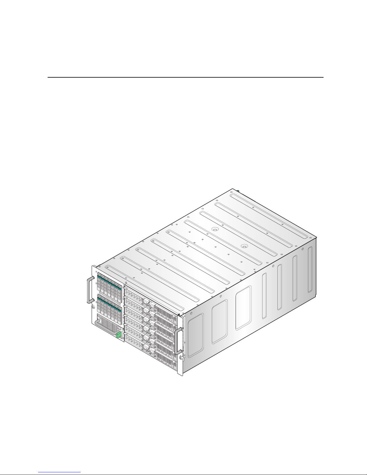
The following three versions of the Intel® Modular Server System are available:
• Intel
• Intel
• Intel
All references in the document to MFSYS25 are for both MFSYS25 and MFSYS25V2.
Exceptions will call out either MFSYS25 or MFSYS25V2. This chapter briefly describes
the main features of the Intel
and illustrations of the product, a features list, and diagrams showing the location of
important components and connections on the server chassis.
®
Modular Server System MFSYS25
®
Modular Server System MFSYS35
®
Modular Server System MFSYS25V2
®
Modular Server System. This chapter provides photographs
Intel® Modular Server System User Guide 1
Figure 1. Intel
®
Modular Server System MFSYS25
Page 18
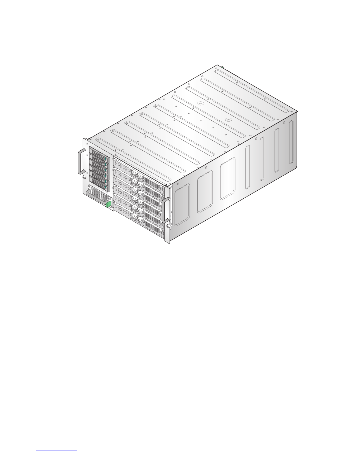
Figure 2. Intel® Modular Server System MFSYS35
AF002661
1
I/O
2
ID
1
2
1
I/O
2
ID
1 2
Modular Server System Feature Overview
Table 1 provides an overview of the modular server system configuration.
2 Intel® Modular Server System User Guide
Page 19

Table 1. Modular Server System Features
Feature Description
Chassis Dimensions
• 10.3 inches (261.4 mm) high – 6U
• 17.5 inches (444.4 mm) wide
• 28.4 inches (720.2) mm long
• 187 lbs (85 kg) - maximum full configuration weight
Module Bays (rear) • Four hot-plug 110/220V power module bays
• Two hot-swap Ethernet switch module bays
• Two hot-swap storage control module bays
• Two hot-swap main cooling module bays
• One hot-swap management module bay
Module Bays (front) • Six hot-plug compute module bays
• One hot-swap I/O cooling module bay
• One hard disk drive bay
Hard Disk Drive Bay • Intel® Modular Server System MFSYS25: 14 hot-swap 2.5-
Intel® Modular Server Control • Powerful integrated management GUI for configuration and
inch SAS hard disk drive carriers with filler blanks installed
(hard disk drives are NOT included)
®
• Intel
Modular Server System MFSYS35: 6 hot-swap 3.5inch SAS or SATA hard disk drive carriers with filler blanks
installed (hard disk drives are NOT included)
chassis management
• Provides a single interface for system updates
Intel® Modular Server Systems Content and References
The following three versions of the Intel® Modular Server System are available:
• Intel
• Intel
• Intel
Intel® Modular Server System MFSYS25 Contents
Your Intel® Modular Server System MFSYS25 ships with the following items:
One Chassis enclosure
One Intel
One Intel
One Intel
Intel® Modular Server System User Guide 3
®
Modular Server System MFSYS25
®
Modular Server System MFSYS35
®
Modular Server System MFSYS25V2
Table 2. Intel® Modular Server System MFSYS25 Contents
Quantity Description
®
Management Module
®
Gigabit Ethernet Switch Module
®
Storage Control Module
Page 20

Table 2. Intel® Modular Server System MFSYS25 Contents
Quantity Description
14 2.5" hard disk drive carriers
Two 1000W Power Supply Modules
Two Main Cooling Fan Modules
One I/O Cooling Fan Module
Two Blank Power Supply Fan Blanks
Five Server Blanks (Compute Module filler panels)
Two Blank filler panels for rear module bays SCM2 and SWM2
One Documentation package including: System Quick Start Guide,
Safety Flyer and Resource CD
Note: The MFSYS25 base configuration does not include hard drives, compute modules or
power cords.
Intel® Modular Server System MFSYS25V2 Contents
You r I nt el® Modular Server System MFSYS25V2 ships with the following items:
Table 3. Intel® Modular Server System MFSYS25V2 Contents
Quantity Description
One Chassis enclosure
One Intel® Management Module 2
One Intel
One Intel® Storage Control Module
14 2.5" hard disk drive carriers
Two 1000W Power Supply Modules
Two Main Cooling Fan Modules
One I/O Cooling Fan Module
Two Blank Power Supply Fan Blanks
Five Server Blanks (Compute Module filler panels)
Two Blank filler panels for rear module bays SCM2 and SWM2
One Documentation package including: System Quick Start Guide,
®
Gigabit Ethernet Switch Module
Safety Flyer and Resource CD
Note: The MFSYS25V2 base configuration does not include hard drives, compute modules or
power cords.
Intel® Modular Server System MFSYS35 Contents
You r I nt el® Modular Server System MFSYS35 ships with the following items:
4 Intel® Modular Server System User Guide
Page 21

Table 4. Intel® Modular Server System MFSYS35 Contents
Quantity Description
One Chassis enclosure
One Intel® Management Module
One Intel
One Intel® Storage Control Module
Six 3.5" hard disk drive carriers
Two 1000W Power Supply Modules
Two Main Cooling Fan Modules
One I/O Cooling Fan Module
Two Blank Power Supply Fan Blanks
Five Server Blanks (Compute Module filler panels)
Two Blank filler panels for rear module bays SCM2 and SWM2
One Documentation package including: System Quick Start Guide,
®
Gigabit Ethernet Switch Module
Safety Flyer and Resource CD
Note: The MFSYS35 base configuration does not include hard drives, compute modules or
power cords.
Intel® Modular Server System User Guide 5
Page 22

Additional Information and Software
If you need more information about this products or information about the accessories that
can be used with this modular server system, use the following resources.
Table 5. Modular Server System References
For this information or
software
For in-depth technical
information about the
modular server system,
including subsystem
overviews and
mechanical drawings
For in-depth technical
information about the
server board, including
board layout, connector
pin-outs, timing
information, mechanical
drawings and LED
information
If you just received this
product and you need to
assemble your modular
server system and install
components
Use this Document or Software
®
Intel
Modular Server System Technical Product Specification
Available at:
http://www.intel.com/p/en_US/support/highlights/server/mfsys25
®
Intel
Compute Module MFS5000SI Technical Product
Specification
Available at:
http://www.intel.com/p/en_US/support/highlights/server/mfs5000si
®
Intel
Compute Module MFS5000SI User Guide
Available at:
http://www.intel.com/p/en_US/support/highlights/server/mfs5000si
®
Intel
Compute Module MFS5520VI Technical Product
Specification
Available at:
http://www.intel.com/p/en_US/support/highlights/server/mfs5520vi
Intel® Compute Module MFS5520VI User Guide
Available at:
http://www.intel.com/p/en_US/support/highlights/server/mfs5520vi
®
Intel
Modular Server System Quick Start User’s Guide
Provided in the product box or available for download at:
http://www.intel.com/p/en_US/support/highlights/server/mfsys25
Accessories or other Intel
server products
6 Intel® Modular Server System User Guide
Spares, Parts List, and Configuration Guide
Available at:
http://www.intel.com/p/en_US/support/highlights/server/mfsys25
or by using the Server Configurator Tool
Available at:
http://serverconfigurator.intel.com/default.aspx
Page 23

Table 5. Modular Server System References
For this information or
software
Hardware (peripheral
boards, adapter cards)
and operating systems
that have been tested with
this product
Processors that have
been tested with this
product
DIMMs that have been
tested with this product
Hard Drives that have
been tested with this
product
Latest drivers, Unified
Firmware Update
packages, and utilities
For software to manage
your Intel
®
server
Use this Document or Software
Server Configurator Tool
Available at:
http://serverconfigurator.intel.com/default.aspx
Available for download at:
http://www.intel.com/p/en_US/support/highlights/server/mfsys25
Click the Software and Drivers link on the left side of the web
page.
®
Modular Server Control UI: The Intel® Management Module
Intel
integrated management interface for the modular server system.
For instructions and information, refer to the Intel® Modular Server
System User Guide.
Available at:
http://www.intel.com/p/en_US/support/highlights/server/mfsys25
Major Components
Front View
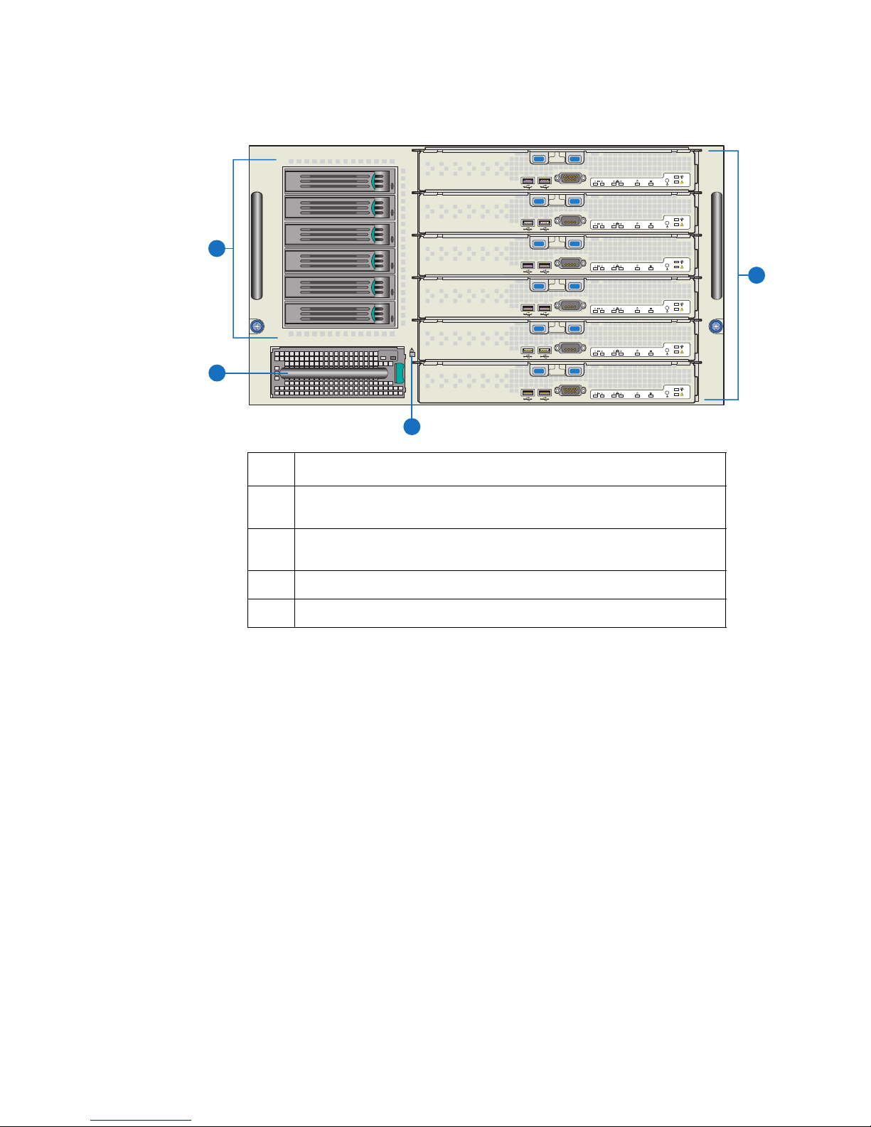
Figure 3 shows the front view of the platform. The front provides access to the following
components.
Intel® Modular Server System User Guide 7
Page 24
Item Description
12
34567
89
10 11
12
13 14
1
2
3
4
5
6
A
AF002062
C
B
D
A Compute modules or filler panels (six) [Compute Module 1 on top and
Compute Module 6 on bottom]
B Hard Disk Drive bay module with hot-swap 2.5-inch SAS hard disk drives
(14) [HDD 1 on the upper left and HDD 14 on the lower right]
C I/O cooling module
D System Status LED
Figure 3. Front View of Intel® Modular Server System MFSYS25
8 Intel® Modular Server System User Guide
Page 25
Item Description
A
AF002657
C
B
D
Compute Module
The Intel® Modular Server System supports up to six compute modules. Each compute
module is a general-purpose server built around the following minimum features:
• Processor(s)
• Memory
• Integrated Baseboard Management Controller
• Network interface
• Storage control module
For more information, refer to the appropriate compute module Technical Product
Specification and User Guide.
A Compute modules or filler panels (six) [Compute Module 1 on top and
Compute Module 6 on bottom]
B Hard Disk Drive bay module with hot-swap 3.5-inch SAS or SATA hard
disk drives (6) [HDD 1 on top and HDD 6 on bottom]
C I/O cooling module
D System Status LED
Figure 4. Front View of Intel® Modular Server System MFSYS35
Hard Disk Drive Bay Module
The Intel® Modular Server System has an integrated hard disk drive bay module with the
following features:
Intel® Modular Server System User Guide 9
Page 26

• Intel
®
Modular Server System MFSYS25 has an integrated hot-swap 2.5-inch SAS
hard disk drive bay module that can support up to a maximum of 14 hard disk drives.
• Intel
®
Modular Server System MFSYS35 has an integrated hot-swap 3.5-inch SAS/
SATA hard disk drive bay module that can support up to a maximum of 6 hard disk
drives.
• Storage configuration and management are supported via the Intel
®
Modular Server
Control UI.
®
To access the installed physical drives, you must install at least one Intel
Storage Control
Module in the rear bay labeled SCM1.
Because hard disk drives have different cooling, power, and vibration characteristics, Intel
validates specific hard disk drive types in the platforms. See the Intel
System Tested Hardware and Operating System List for a list of qualified drives.
I/O Cooling Module
The I/O cooling module consists of six fans in a hot-swap module with power and status
indicators. These fans provide cooling for all I/O modules. The I/O cooling module is
accessible from the front of the system even though it cools the I/O modules in the rear of
the system.
®
Modular Server
10 Intel® Modular Server System User Guide
Page 27
Rear View
AF002064
C
B
D
E
A
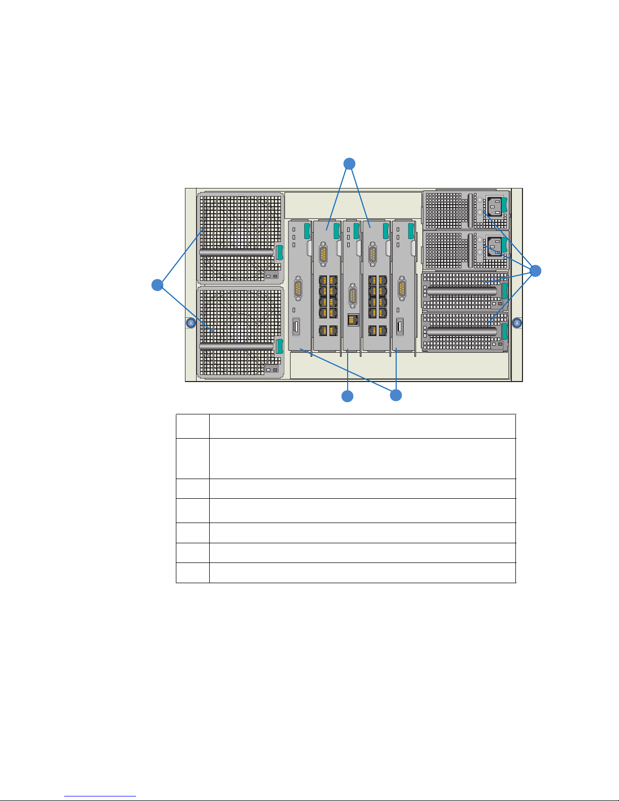
Figure 5 shows a rear view of the platform. The rear provides access to the following
components:
Item Description
A Power supply module bays (four) (as illustrated: two top bays occupied by
power supply modules; two bottom bays occupied by power supply
blanks)
B Main cooling module bays (two)
I/O Module Slots
C Ethernet switch module slots (two)
D Storage control module slots (two)
E Management module slot (one)
Figure 5. Rear View of Server System
Power Supply Module
Up to four hot-swap power supply modules can be installed in the right rear of the chassis.
Each supply has its own AC input power connector and is rated at 1000 watts over an
input range of 100-240 VAC. Each power supply includes two fans that provide cooling
for hot-swap disk drives. All four power supply bays must be populated with either a
power supply module or a power supply blank. The power supply blank has two fans that
ensure proper system cooling.
Intel® Modular Server System User Guide 11
Page 28

One power supply supports one compute module plus all other modules in the system.
Two power supplies support two to three compute modules (in any slot) plus all other
modules in the system.
Three power supplies support four to six compute modules (in any slot) plus all other
modules in the system.
Any additional power supplies above the minimum required (based on configuration)
provide redundancy.
I/O Module Slots
The middle-rear of the chassis can accommodate up to four expansion modules.
Ethernet Switch Module
One or two hot-swap Intel
switch has ten uplink ports and twelve internal server bay ports, two ports routed to each
compute module. One switch module is the minimum configuration; a second switch
module allows for network redundancy.
Storage Control Module
One or two hot-swap Intel
SAS hard drives in the Intel
SAS/SATA hard drives in the Intel
control module is the minimum configuration; a second storage control module allows for
storage control module redundancy. When two storage control modules are installed and
one fails, drive access is maintained through the operational storage control module.
®
Gigabit Ethernet Switch Modules can be installed. Each
®
Storage Control Modules can be used for up to 14 hot-swap
®
Modular Server System MFSYS25 and up to 6 hot-swap
®
Modular Server System MFSYS35. One storage
Management Module
®
The Intel
Management Module 2 is installed in the middle-rear of the chassis, between
the four I/O slots. This module provides an Internet browser interface that enables the
configuration and management of the entire modular server system. This module is not
redundant but the system will continue to operate normally if this module fails. However,
any changes to the system configuration will not be recognized until the failed
management module is replaced.
Main Cooling Modules
Two hot-swap main cooling modules are installed on the left rear of the chassis. Each
module contains a redundant fan. Main cooling modules maintain separate zones in the
chassis. Both modules are required to properly cool all compute modules.
12 Intel® Modular Server System User Guide
Page 29
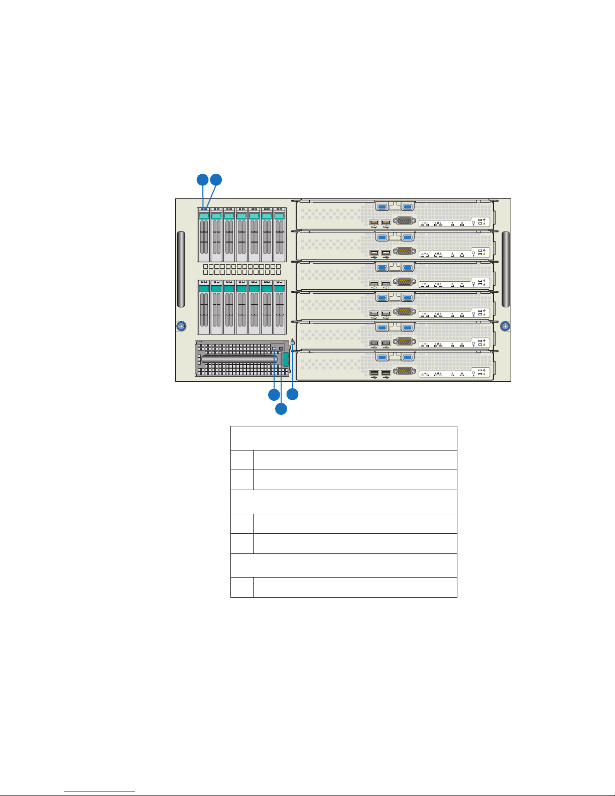
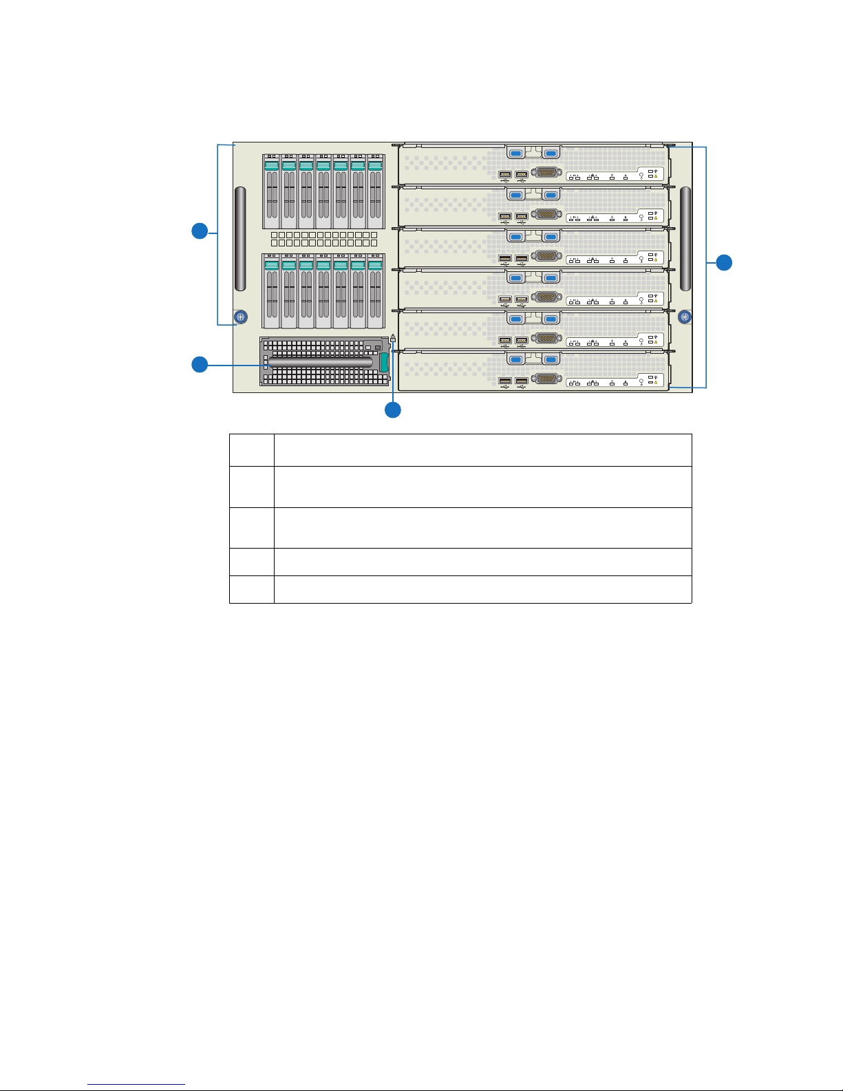
Front Chassis Connectors and Indicators
12
34567
89
10 11
12
13 14
1
2
3
4
5
6
A
AF002063
B
C
D
E
The indicator modes for the Hard Drive Carrier, I/O Cooling Module, and Chassis
indicators illustrated in the following figures are described in “Diagnostic LED
Information” on page 141.
A Hard drive power/activity LED – Green
B Hard drive fault LED – Amber
C I/O cooling module power LED – Green
D I/O cooling module fault LED – Amber
E System Fault LED - Amber
Figure 6. Intel
Hard Drive Carrier
I/O Cooling Module
Chassis
®
Modular Server System MFSYS25 Front Chassis
Connectors and Indicators
Intel® Modular Server System User Guide 13
Page 30
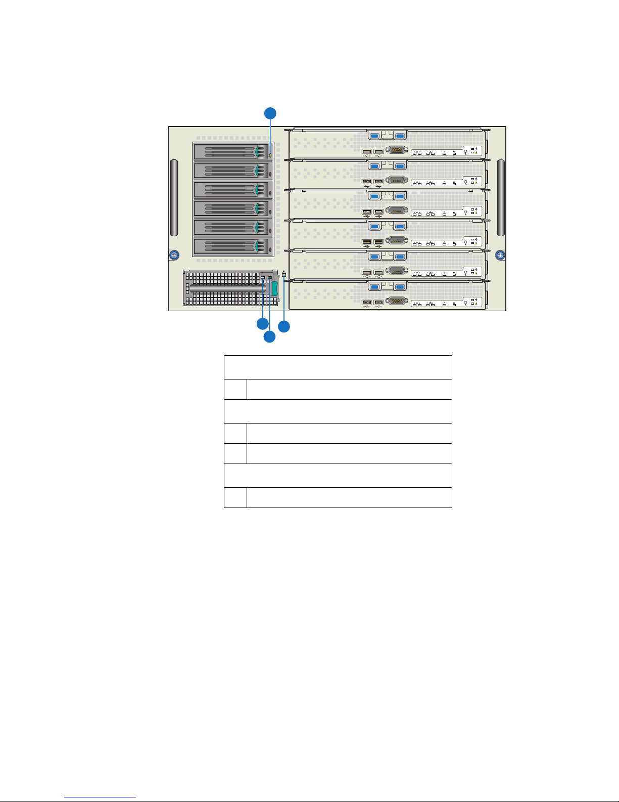
Hard Drive Carrier
AF002658
C
B
A
D
A Hard drive power/activity LED – Green
I/O Cooling Module
B I/O cooling module power LED – Green
C I/O cooling module fault LED – Amber
Chassis
D System Fault LED - Amber
Figure 7. Intel® Modular Server System MFSYS35 Front Chassis
Connectors and Indicators
Compute Module Connectors and Indicators
For detailed information on compute module connectors and indicators, refer to the
appropriate compute module Technical Product Specification and User Guide.
14 Intel® Modular Server System User Guide
Page 31

Back Chassis Connectors and Indicators
AF002065
G
J
H
LIK
FED
A
M
C
B
O N
P
Storage Control Module
A Storage control module dirty cache LED – Green
B Storage control module fault LED – Amber
C Storage control module power LED – Green
M Storage control module Ethernet SAS connector
Ethernet Switch Module
D Ethernet switch module power LED – Green
E Ethernet switch module fault LED – Amber
L Ethernet switch module 1-Gb Ethernet connectors (10) with LEDs
P Serial cable connectors (manufacturing only)
Management Module
F Management module power LED – Green
G Management module fault LED – Amber
H Management module reset switch
K Management module NIC connectors with LEDs
I Power supply module power LED – Green
J Power supply fault indicator LED – Amber
N Main cooling module fault LED – Amber
O Main cooling module power LED – Green
Power Supply Module
Main Cooling Module
Intel® Modular Server System User Guide 15
Figure 8. Rear Chassis Connectors and Indicators
Page 32

All indicator modes are described in “Diagnostic LED Information” on page 141.
Rack Mount Options
You r I nt el® Modular Server System MFSYS25/MFSYS35 can be mounted into a 4-post
fixed mount rack.
16 Intel® Modular Server System User Guide
Page 33

2 Hardware Installations and Upgrades
Before You Begin
Before working on your server system, review the safety and ESD information at the
beginning of this manual and in the appendices.
Tools and Supplies Needed
• Phillips
*
(cross head) screwdriver (#1 bit and #2 bit)
• Needle-nosed pliers
• A ruler
• Pen or pencil
• Anti-static wrist strap and conductive foam pad (recommended)
Chassis References
All references to left, right, front, top, and bottom are based on the reader facing the front
of the chassis as it would be positioned for normal operation.
Installing the Intel® Modular Server System MFSYS25/MFSYS35
in a Rack
The Intel® Modular Server System MFSYS25/MFSYS35 is designed for fixed mount
rack installation only; all service events will be performed from either the front or back of
the system.
Caution: When removing the system from its packaging, DO NOT lift the system by the power
supply or fan module handles.
Installation Guidelines
• Review the safety and ESD information at the beginning of this manual and in the
appendices.
• Use a mechanical lift to install the Intel
MFSYS35 in a rack cabinet.
• When lifting the system, DO NOT lift by the power supply or fan module handles.
• All compute modules, hard drives, power supply modules, I/O modules, and cooling
modules should be removed before placing the Intel
MFSYS25/MFSYS35 in a rack.
Intel® Modular Server System User Guide 17
®
Modular Server System MFSYS25/
®
Modular Server System
Page 34

• The Intel
®
Modular Server System MFSYS25/MFSYS35 can only be installed in a
rack cabinet with perforated front and rear doors.
• Plan device installation starting with the bottom of the rack cabinet.
• Do not leave unused space within the rack cabinet opening; blank filler panels must be
used to fill gaps and prevent recirculation of warm air.
• Ensure the power outlets in the rack are sufficient in quantity and load capacity to
support all devices intended to be installed in the rack.
Installing Temporary Handles on System
Temporary handles are provided with your Intel® Modular Server System. These handles
are intended to aid in the movement of the system during removal from packaging and
during initial configuration and installation. However, the profile of the handles is such
that it prevents their use when the system is installed in a standard 19-inch rack.
To install the temporary handles on the system, follow these steps:
1. Mount the handles to the top edges of both the front and rear of the system.
2. Insert the handle tabs of each front and rear handle into the chassis slots and tighten
captive screws.
1
2
3
4
5
6
7
8
9
1
0
1
1
1
2
1
3
1
4
1
I/O
2
1
2
ID
1
2
3
4
5
1
I/O
2
1
2
ID
6
AF002418
Figure 9. Installing Temporary Handles
The system can now be moved as required to aid in removal from packaging, installation
of the remaining modules in the system, or installation of the system in a rack.
18 Intel® Modular Server System User Guide
Page 35

Warni n g: If using the handles during rack installation, the rear handles must be removed prior to
setting the system on the rack rails to avoid interference of the handles with the rack. The
front handles must also be removed before sliding the system completely into the rack and
securing the front chassis tabs to the rack.
Mounting System in Rack
Please read the safety information at the beginning of this book before installing the
chassis in a rack.
Warni n g: If you have installed temporary handles to aid in moving and/or configuring the system,
you must remove the rear handles prior to setting the system on the rack rails to avoid
interference of the handles with the rack. The front handles must also be removed before
sliding the system completely into the rack and securing the front chassis tabs to the rack.
1. Review the safety and ESD information at the beginning of this manual and in the
appendices.
2. Identify the location within the rack where the server system is to be installed.
3. Install the rack mount rails as described in the rail installation instructions.
4. Remove the compute modules, hard drives, power supply modules, I/O modules, and
cooling modules.
5. Working with at least two people, slide the server system into the rack so that it rests
on the rack mounting rails.
6. Secure the server system in the rack as described in the rail installation instructions.
7. Install all compute modules, hard drives, power supply modules, I/O modules, and
cooling modules.
Hot-Swap Module Installation and Removal Guidelines
• The green color on components and labels in your chassis identifies hot-swap
components. You can install or remove hot-swap modules and hot-plug compute
modules, with some restrictions, while the server system is powered on.
• You do not need to disconnect the server system from power to install or replace any
of the hot-swap modules; however, to avoid data corruption, you must shut down the
operating system and power off the compute module before removing it from the
server system.
• Hot-swap cooling modules must be replaced within one minute. All other hot-swap
and hot-plug components must be replaced within two minutes. Compute modules,
management modules, switch modules, storage control modules, power modules, and
cooling modules should be replaced with a like component or a filler panel within two
minutes.
Intel® Modular Server System User Guide 19
Page 36

Replacing the Management Module
The Intel® Modular Server System MFSYS25/MFSYS35 ships with a management
module pre-installed in the middle bay of the rear of the chassis. The middle bay is
dedicated to the management module and is labeled CMM. For the exact location of the
management module bay, see Figure 5.
The management module can only be installed in a module bay that is designed to support
that device type. If necessary, the management module may be removed and replaced
using the steps detailed in the following sections:
• “Removing the Management Module” on page 20
• “Installing the Management Module” on page 21
Removing the Management Module
To remove the management module, follow these steps:
1. Review the safety and ESD information at the beginning of this manual and in the
appendices.
2. Remove the Ethernet cable from the management module.
3. Press the retention latch (see letter “A” in Figure 10) to release the retention lever.
4. Rotate the lever out and away from the module bay (see letter “B” in Figure 10) and
pull the module straight out the back of the chassis (see letter “C” in Figure 10).
20 Intel® Modular Server System User Guide
Page 37

AF002436
C
B
A
Figure 10. Removing the Management Module
5. Install another management module in the management module bay within two
minutes.
Installing the Management Module
To install the management module, follow these steps:
1. Review the safety and ESD information at the beginning of this manual and in the
appendices.
2. Locate the management module bay and remove the module to be replaced.
Intel® Modular Server System User Guide 21
Page 38

3. Release and rotate the module retention lever out and away from the replacement
management module (see letter “A” in Figure 11).
4. Slide the replacement management module into the management module bay (see
letter “B” in Figure 10) until the bottom of the retention lever engages with the
module bay.
B
5. Rotate the lever handle in toward the module bay until it is latched.
6. Reconnect the Ethernet management port to the management network.
22 Intel® Modular Server System User Guide
A
AF002414
Figure 11. Installing the Management Module
Page 39

Installing and Removing an Ethernet Switch Module
The Intel® Modular Server System MFSYS25/MFSYS35 ships with one Ethernet switch
module pre-installed. Optionally, a second switch module may be installed in the second
switch module bay. An ethernet switch module can only be installed in a module bay that
is designed to support that device type. The two bays located immediately to the left and
right of the Management Module are dedicated to the Ethernet Switch Modules and are
labeled ESM. For the exact location of the switch module bay, see Figure 5.
The Ethernet switch module may be removed and installed using the steps detailed in the
following sections:
• “Installing an Ethernet Switch Module” on page 23
• “Removing an Ethernet Switch Module” on page 24
Installing an Ethernet Switch Module
To install an ethernet switch module, follow these steps:
1. Review the safety and ESD information at the beginning of this manual and in the
appendices.
2. Locate an available switch bay and remove any installed module or filler panel.
3. Release and rotate the module retention lever out and away from the switch module
(see letter “A” in Figure 12).
4. Slide the switch module into the selected module bay (see letter “B” in Figure 12)
until the bottom of the retention lever engages the bay.
Intel® Modular Server System User Guide 23
Page 40

B
A
5. Rotate the lever handle in toward the module bay until it is latched.
6. Connect one or more Ethernet switch ports to your network as is appropriate.
Removing an Ethernet Switch Module
To remove an ethernet switch module, follow these steps:
1. Review the safety and ESD information at the beginning of this manual and in the
appendices.
2. Remove and label the connected Ethernet cables, as necessary.
3. Press the retention latch (see letter “A” in Figure 13) to release the retention lever.
4. Rotate the lever out and away from the module bay (see letter “B” in Figure 13) and
pull the module straight out the back of the chassis (see letter “C” in Figure 13).
24 Intel® Modular Server System User Guide
AF002437
Figure 12. Installing an Ethernet Switch Module
Page 41

AF002413
C
B
A
Figure 13. Removing an Ethernet Switch Module
5. Install a filler panel or another Ethernet switch module in the switch module bay
within two minutes.
Intel® Modular Server System User Guide 25
Page 42

Installing and Removing a Storage Control Module
The Intel® Modular Server System MFSYS25/MFSYS35 ships with one storage control
module pre-installed. Optionally, a second storage control module may be installed in the
open storage control module bay. A Storage Control module can only be installed in a
module bay that is designed to support that device type. The farthest bay on the left and
the farthest bay on the right are dedicated to the Storage Control Modules and are labeled
SCM. For the exact location of the storage control module bay, see Figure 5.
The Storage Control module may be removed and installed using the steps detailed in the
following sections:
• “Installing a Storage Control Module” on page 26
• “Removing a Storage Control Module” on page 27
Installing a Storage Control Module
To install a storage control module, follow these steps:
1. Review the safety and ESD information at the beginning of this manual and in the
appendices.
2. Locate an available storage control module bay and remove any installed module or
filler panel.
3. Release and rotate the module retention lever out and away from the storage control
module (see letter “A” in Figure 14).
4. Slide the storage control module into the selected module bay (see letter “B” in
Figure 14) until the bottom of the retention lever engages with the module bay.
26 Intel® Modular Server System User Guide
Page 43

B
A
AF002412
Figure 14. Installing a Storage Control Module
5. Rotate the lever handle in toward the module bay until it latches.
Removing a Storage Control Module
If only one Intel® Storage Control Module is installed in the Intel® Modular Server
System, power off all compute modules prior to removing the Intel
Module
To remove a storage control module, follow these steps:
1. Review the safety and ESD information at the beginning of this manual and in the
appendices.
Intel® Modular Server System User Guide 27
®
Storage Control
Page 44

2. Press the retention lever latch button to release the retention lever (see letter “A” in
AF002430
A
C
B
Figure 15).
3. Rotate the lever out and away from the module bay (see letter “B” in Figure 15) and
pull the storage control module straight out the back of the chassis (see letter “C” in
Figure 15).
Warni n g: You must replace the storage control module with a filler panel or
another storage control module within two minutes.
Figure 15. Removing a Storage Control Module
4. Install a filler panel or another storage control module in the storage control module
bay within two minutes.
28 Intel® Modular Server System User Guide
Page 45

Installing and Removing the Backup Battery
A
B
C
AF002563
Installing a Backup Battery
To install a backup battery, follow these steps:
1. Review the safety and ESD information at the beginning of this manual and in the
appendices.
2. Remove the storage control module from the system. For instructions, see “Removing
a Storage Control Module” on page 27.
Warnin g: You must replace the storage control module with a filler panel or
another storage control module within two minutes.
3. Place the storage control module sideways on a work surface so that its largest surface
area is touching the work surface and the retention lever is on the top.
4. With a Phillips* screwdriver, remove the screw securing the top cover to the storage
control module (see letter “A” in Figure 16).
Figure 16. Removing Top Cover from Storage Control Module
5. Slide the cover towards the rear of the storage control module (see letter “B” in
Figure 16) and lift upward (see letter “C” in Figure 16).
Intel® Modular Server System User Guide 29
Page 46

6. Install the backup battery in the black plastic battery holder (see letter “A” in
Figure 17). Connect the battery cable to the battery connector on the printed circuit
board (see letter “B” in Figure 17).
A
B
AF002440
Figure 17. Installing Backup Battery
7. Align notches in the top cover with corresponding tabs in the storage control module.
Slide the top cover forward to close.
8. Secure the top cover to the storage control module with the two screws previously
removed.
9. Re-install the storage control module in the server system. For instructions, see
“Installing a Storage Control Module” on page 26.
Removing a Backup Battery
To remove a backup battery, follow these steps:
1. Review the safety and ESD information at the beginning of this manual and in the
appendices.
2. Remove the storage control module from the system. For instructions, see “Removing
a Storage Control Module” on page 27.
Warni n g: You must replace the storage control module with a filler panel or
30 Intel® Modular Server System User Guide
another storage control module within two minutes.
Page 47

3. Place the storage control module sideways on a work surface so that its largest surface
A
B
C
AF002563
area is touching the work surface and the retention lever is on the top.
4. With a Phillips* screwdriver, remove the screw securing the top cover to the storage
control module (see letter “A” in Figure 18).
Figure 18. Removing Top Cover from Storage Control Module
5. Slide the cover towards rear of the storage control module (see letter “B” in
Figure 18) and lift upward (see letter “C” in Figure 18).
Intel® Modular Server System User Guide 31
Page 48

6. Disconnect the battery cable from the battery connector on the printed circuit board
(see letter “A” in Figure 19). Remove the battery from the black plastic battery holder
(see letter “B” in Figure 19).
B
A
AF002461
Figure 19. Removing Backup Battery
7. Align notches in the top cover with corresponding tabs in the storage control module.
Slide the top cover forward to close.
8. Secure the top cover to the storage control module with the two screws previously
removed.
9. Re-install the storage control module in the server system. For instructions, see
“Installing a Storage Control Module” on page 26.
Installing and Removing a Power Supply Module
The Intel® Modular Server System MFSYS25/MFSYS35 ships with two power supply
modules pre-installed. A single power supply is suitable to support the power requirement
for the chassis, including fan modules, storage control module, switch module, storage
bay, and a single compute module. Additional power modules are required as the number
of installed compute modules increases.
Note: One power supply module supports one compute module plus all other modules in the
system.
Two power supply modules support two to three compute modules (in any slot) plus all
other modules in the system.
32 Intel® Modular Server System User Guide
Page 49

Three power supply modules support four to six compute modules (in any slot) plus all
AF002420
B
A
other modules in the system.
Any additional power supply modules above the minimum required (based on
configuration) provide redundancy.
Installing a Power Supply Module
To install a power supply module, follow these steps:
1. Review the safety and ESD information at the beginning of this manual and in the
appendices.
2. Locate the power supply module bay and remove any installed module or filler
module.
— For instructions on removing a power supply module, see “Removing a Power
Supply Module” on page 34.
— To remove a filler module, press the retention lever latch (see letter “A” in
Figure 20) to release the filler module from the module bay. Slide the filler
module out of the bay (see letter “B” in Figure 20).
Intel® Modular Server System User Guide 33
Figure 20. Removing Filler Module
Page 50

3. Slide the power supply module into the power supply module bay until the retention
AF002434
latch engages.
Figure 21. Installing Power Supply Module
4. Connect a power cable from the power supply module to an appropriate power source.
Removing a Power Supply Module
To remove a power supply module, follow these steps:
1. Review the safety and ESD information at the beginning of this manual and in the
appendices.
2. Locate the power supply module to be removed.
3. Remove the power cord from both the power supply module and the power source.
34 Intel® Modular Server System User Guide
Page 51

4. Press the power supply module retention latch to release the power supply module
AF002433
B
A
from the bay (see letter “A” in Figure 22). Slide the power supply module out of the
module bay (see letter “B” in Figure 22).
5. Replace the power supply module with a filler panel or another power supply module
within two minutes.
Replacing a Main Cooling Module
The Intel® Modular Server System MFSYS25/MFSYS35 ships with two main cooling
modules pre-installed at the back of the chassis. For the exact location of the Main
Cooling Modules, see Figure 5.
Intel® Modular Server System User Guide 35
Figure 22. Removing a Power Supply Module
Page 52

Removing a Main Cooling Module
To remove a main cooling module, follow these steps:
1. Review the safety and ESD information at the beginning of this manual and in the
appendices.
2. Locate the main cooling module to be replaced.
3. Press the main cooling module retention clip to release the main cooling module from
the module bay (see letter “A” in Figure 23).
4. Slide the main cooling module out of the module bay (see letter “B” in Figure 23).
Warni n g: Replace the cooling module with another cooling module within two minutes.
5. Install another cooling module into the cooling module bay within two minutes.
36 Intel® Modular Server System User Guide
B
A
AF002438
Figure 23. Removing a Main Cooling Module
Page 53

Installing a Main Cooling Module
To install a main cooling module, follow these steps:
1. Review the safety and ESD information at the beginning of this manual and in the
appendices.
2. Locate the cooling module bay and remove the cooling module to be replaced.
3. Slide the replacement cooling module into the unoccupied cooling module bay until
the retention latch engages (see Figure 24).
Replacing the I/O Cooling Module
The Intel® Modular Server System MFSYS25/MFSYS35 ships with one I/O cooling
module pre-installed at the front of the chassis. For the exact location of the I/O Cooling
Module in
Intel® Modular Server System User Guide 37
AF002439
Figure 24. Installing a Main Cooling Module
Page 54

• Intel
A
B
8
9
1
0
1
1
1
2
1
3
1
4
1
2
3
4
5
6
7
AF003160
• Intel
®
Modular Server System MFSYS25, see Figure 3
®
Modular Server System MFSYS35, see Figure 4.
Removing the I/O Cooling Module
To remove the I/O cooling module, follow these steps:
1. Review the safety and ESD information at the beginning of this manual and in the
appendices.
2. Locate the I/O cooling module to be replaced.
3. Press the I/O cooling module retention latch to release the I/O cooling module from
the module bay (see letter “A” in Figure 26).
4. Slide the I/O cooling module out of the module bay (see letter “B” in Figure 26).
5. Install another cooling module into the cooling module bay within two minutes.
38 Intel® Modular Server System User Guide
Figure 25. Removing an I/O Cooling Module
Page 55

Installing the I/O Cooling Module
To install the I/O cooling module, follow these steps:
1. Review the safety and ESD information at the beginning of this manual and in the
appendices.
2. Locate the cooling module bay and remove the cooling module to be replaced.
3. Slide the replacement I/O cooling module into the vacant module bay (see Figure 26)
until the retention latch engages.
Warni n g: Replace the cooling module with another cooling module within two minutes.
1
2
3
4
5
6
7
8
9
1
0
1
1
1
2
1
3
1
4
Installing and Removing Hard Drives
The Intel® Modular Server System MFSYS25/MFSYS35 provides storage for installed
compute modules by way of an on-board storage bay combined with a storage
management module. The on-board storage bay supports the installation of up to 14 hotswap 2.5-inch SAS/SATA hard drives in the Intel
6 hot-swap 3.5-inch SAS/SATA hard drives in the Intel
MFSYS35 that are configured through the integrated Intel
For more information, see “Using the Intel
page 57.
Intel® Modular Server System User Guide 39
AF002417
Figure 26. Installing an I/O Cooling Module
®
Modular Server System MFSYS25 or
®
Modular Server System
®
®
Modular Server Control User Interface” on
Modular Server Control UI.
Page 56

Caution: Only hard drives validated for use in the Intel® Modular Server System MFSYS25/
AF002425
B
A
8
9
1
0
1
1
1
2
1
3
1
4
1
2
3
4
5
6
7
MFSYS35 should be installed. You may damage the Intel
®
Modular Server System
MFSYS25/MFSYS35 if you install a hard drive that is not listed in the Intel
Server System Tested Hardware and Operating System List.
Installing a 2.5-inch Hard Drive into the Storage Bay
To install a 2.5-inch hard drive into the storage bay, follow these steps:
1. Review the safety and ESD information at the beginning of this manual and in the
appendices.
2. Press the retaining lever on an available drive carrier to release the drive carrier from
the drive bay module (see letter “A” in Figure 27). Remove the drive carrier from the
drive bay module (see letter “B” in Figure 27).
®
Modular
Figure 27. Removing a 2.5-inch Drive Carrier from a Drive Bay Module
3. With a Phillips* screwdriver, remove the four screws securing the filler panel to the
drive carrier.
40 Intel® Modular Server System User Guide
Page 57

4. Align the holes in the hard drive to the holes in the drive carrier (see letter “A” in
AF002428
B
A
Figure 28) and attach it to the drive carrier using the four screws removed in the
previous step (see letter “B” in Figure 28).
Figure 28. Installing Hard Drive into Drive Carrier
Intel® Modular Server System User Guide 41
Page 58

5. For 2.5" SSD and SATA hard drives, attach the AXXTM3SATA (SATA to SAS
Converter Board) to the drive. See the below figure.
6. With the drive carrier retaining lever in the open position (see letter “A” in Figure 30),
carefully slide the drive carrier into the drive bay module until it is fully seated and
the retaining lever starts to engage. Press firmly to latch the retaining lever (see letter
“B” in Figure 30).
42 Intel® Modular Server System User Guide
Figure 29. Attaching AXXTM3SATA to the Drive
Page 59

Figure 30. Installing 2.5-inch Drive Carrier in Drive Bay Module
AF002426
A
B
8
9
1
0
1
1
1
2
1
3
1
4
1
2
3
4
5
6
7
Removing a 2.5-inch Hard Drive from the Storage Bay
To remove a 2.5-inch hard drive from the storage bay, follow these steps:
1. Review the safety and ESD information at the beginning of this manual and in the
appendices.
2. To avoid data corruption, ensure that the drive you intend to remove is not online and
actively providing data storage to any of the installed compute modules.
Intel® Modular Server System User Guide 43
Page 60

3. Press the retaining lever on the selected drive carrier to release the drive carrier from
AF002425
B
A
8
9
1
0
1
1
1
2
1
3
1
4
1
2
3
4
5
6
7
the drive bay module (see letter “A” in Figure 31). Remove the drive carrier from the
drive bay module (see letter “B” in Figure 31).
Figure 31. Removing a 2.5-inch Drive Carrier from the Drive Bay Module
44 Intel® Modular Server System User Guide
Page 61

4. With a Phillips* screwdriver, remove the four screws securing the hard drive to the
drive carrier (see letter “A” in Figure 32). Lift the hard drive from the carrier (see
letter “B” in Figure 32) and store the hard drive in an anti-static container or bag.
B
A
AF002429
Figure 32. Removing Hard Drive from a Drive Carrier
Intel® Modular Server System User Guide 45
Page 62

5. For 2.5" SSD and SATA hard drives, remove the AXXTM3SATA (SATA from SAS
Converter Board) from the drive. See the below figure.
Figure 33. Removing AXXTM3SATA from the Drive
6. Install either another hot-swap hard drive or a filler blank in the drive carrier.
7. Install the drive carrier into the empty drive bay module within two minutes; this step
is required to maintain proper airflow throughout the chassis and to ensure proper
system cooling.
Installing a 3.5-inch Hard Drive into the Storage Bay
To install a 3.5-inch hard drive into the storage bay, follow these steps:
1. Review the safety and ESD information at the beginning of this manual and in the
appendices.
46 Intel® Modular Server System User Guide
Page 63

2. Press the retaining lever on an available drive carrier to release the drive carrier from
the drive bay module (see letter “A” in Figure 34). Remove the drive carrier from the
drive bay module (see letter “B” in Figure 34).
B
A
AF002662
Figure 34. Removing a 3.5-inch Drive Carrier from the Drive Bay Module
3. With a Phillips* screwdriver, remove the four screws securing the filler panel to the
drive carrier.
Intel® Modular Server System User Guide 47
Page 64

4. Align the holes in the hard drive to the holes in the drive carrier (see letter “A” in
AF00317
B
A
Figure 35) and attach it to the drive carrier using the four screws removed in the
previous step (see letter “B” in Figure 35).
Figure 35. Installing Hard Drive into Drive Carrier
48 Intel® Modular Server System User Guide
Page 65

5. With the drive carrier retaining lever in the open position (see letter “A” in Figure 36),
carefully slide the drive carrier into the drive bay module until it is fully seated and
the retaining lever starts to engage. Press firmly to latch the retaining lever (see letter
“B” in Figure 36).
A
B
AF002663
Figure 36. Installing 3.5-inch Drive Carrier in Drive Bay Module
Removing a 3.5-inch Hard Drive from the Storage Bay
To remove a 3.5-inch hard drive from the storage bay, follow these steps:
1. Review the safety and ESD information at the beginning of this manual and in the
appendices.
2. To avoid data corruption, ensure that the drive you intend to remove is not online and
actively providing data storage to any of the installed compute modules.
Intel® Modular Server System User Guide 49
Page 66

3. Press the retaining lever on the selected drive carrier to release the drive carrier from
AF002662
B
A
the drive bay module (see letter “A” in Figure 37). Remove the drive carrier from the
drive bay module (see letter “B” in Figure 37).
Figure 37. Removing a 3.5-inch Drive Carrier from the Drive Bay Module
50 Intel® Modular Server System User Guide
Page 67

4. With a Phillips* screwdriver, remove the four screws securing the hard drive to the
drive carrier (see letter “A” in Figure 38). Lift the hard drive from the carrier (see
letter “B” in Figure 38) and store the hard drive in an anti-static container or bag.
B
A
AF003171
Figure 38. Removing Hard Drive from a Drive Carrier
5. Install either another hot-swap hard drive or a filler blank in the drive carrier.
6. Install the drive carrier into the empty drive bay module within two minutes; this step
is required to maintain proper airflow throughout the chassis and to ensure proper
system cooling.
Intel® Modular Server System User Guide 51
Page 68

Installing and Removing an Intel® Compute Module
1
I/O
2
ID
1
2
Installing an Intel® Compute Module
To install an Intel® Compute Module, follow these steps:
1. Review the safety and ESD information at the beginning of this manual and in the
appendices.
2. If you have not done so already, install any necessary options, such as processor and
memory, in the compute module.
Note: The top cover is a required component of the compute module assembly. Do
not attempt to insert a compute module into the chassis without ensuring an
installed top cover is in place.
3. Make sure the release handles on the compute module are in the open position (see
letter “A” in Figure 39). Insert the compute module into an open slot in the chassis
and slide it in until it stops (see letter “B” in Figure 39).
1
2
3
4
5
6
7
8
9
10
1
1
1
2
1
3
1
4
B
A
1
I/O
2
1 2
ID
A
Figure 39. Installing an Intel
®
Compute Module
4. Close the release handles on the front of the compute module.
1
2
3
4
5
6
AF002431
52 Intel® Modular Server System User Guide
Page 69

Removing an Intel® Compute Module
1
I/O
2
ID
1
2
To remove an Intel® Compute Module, follow these steps:
1. Review the safety and ESD information at the beginning of this manual and in the
appendices.
2. If the compute module is operating, shut down the operating system and power it
down.
3. Open the two release handles at the front of the compute module (see letter “A” in
Figure 40) and pull the compute module out of the server system (see letter “B” in
Figure 40).
1
2
3
4
5
6
7
8
9
1
0
1
1
1
2
1
3
14
1
2
3
4
B
5
6
A
4. Place either a filler or another compute module in the bay within two minutes. This
step is required to maintain proper airflow throughout the server system and to ensure
proper system cooling.
Intel® Modular Server System User Guide 53
1
I/O 2
1 2
ID
A
Figure 40. Removing an Intel
®
Compute Module
AF002432
Page 70

54 Intel® Modular Server System User Guide
Page 71

3 Using the Modular Server System
Minimum Hardware Requirements
To successfully power up the Intel® Modular Server System MFSYS25/MFSYS35 and to
avoid integration difficulties and possible system damage, your modular server system
must meet the minimum hardware requirements listed in the
following table.
Table 6. Hardware Requirements
Component Quantity Location
Ethernet switch module 1 Slot labeled SWM1
Storage control module 1 Slot labeled SCM1
Management module 1 Slot labeled CMM
Power supply module 1* Power supply module bay 1
Power supply blank 3 Power supply module bays 2, 3 and 4
I/O cooling module 1 I/O cooling module bay
Main cooling module 2 Main cooling module bays 1 and 2
Intel® Compute Module 1 Compute module slot 1
Compute module blanks 5 Compute module slots 2, 3, 4, 5, and 6
Note: * Base MFSYS25 and MFSYS35 configurations include two power supply
modules and two blank power supply fan modules
Starting Up Server System
The Intel® Modular Server System MFSYS25/MFSYS35 does not have a power switch.
When the chassis has at least one power supply with power cord plugged into an
appropriate electrical outlet, standby power is available. With standby current, a user can
remotely connect to the management module and/or power on a compute module. Each
compute module has a front panel power switch. Refer to the appropriate compute module
Technical Product Specification and User Guide.
Intel® Modular Server System User Guide 55
Page 72

Installing an Operating System
Before installing an operating system, you must first configure storage and networking via
the management module’s graphical user interface (GUI).
One possible way to install an operating system is as follows:
1. Connect a remote client machine to the management module in the Intel
Server System MFSYS25/MFSYS35 via a cross-over cable.
2. Connect a USB hub to one of the USB ports to allow more than two USB devices to
be used.
3. Connect a video monitor and USB mouse and keyboard to the front of the compute
module using the USB hub.
4. Connect a USB CD-ROM/DVD-ROM drive to the compute module.
5. From the remote client machine, log into the management module and configure
storage and (optionally) networking for the compute module.
6. Power on the CD-ROM/DVDROM drive and insert the operating system
install media.
7. Power on the compute module and install the operating system.
®
Modular
For configuration details, see “Using the Intel
on page 57.
Monitoring the Server System
The management module reports complete system health. From a remote client, an IT
administrator can easily monitor the state of the server system. For more details, see
“Using the Intel
®
Modular Server Control User Interface” on page 57 .
Shutting Down the Server System
To remove power from the Intel® Modular Server System MFSYS25/MFSYS35, you
must first properly power down all compute modules. Next, disconnect all power cables
from the power source. For more information on powering down the compute module(s),
refer to the Intel
®
Compute Module MFS50000SI User Guide.
®
Modular Server Control User Interface”
56 Intel® Modular Server System User Guide
Page 73

4 Using the Intel
User Interface
®
Modular Server Control
This section provides an overview of the Intel® Modular Server Control for the Intel
Modular Server System MFSYS25/MFSYS35. The Intel® Modular Server Control User
Interface (UI) provides complete system hardware management by enabling users to
securely configure and monitor the system. The system is intended to be managed over a
secure, private management network. It is recommended that the Intel
Module not be connected to a publicly accessible network.
Full system management is only supported via the Intel
addition to the Intel
information remotely via SNMP. For information regarding SNMP v2 and v3 support,
refer to the installed Unified Firmware Update (UFU) Release Notes.
This section covers the Intel
instructions for configuring the modular server system.
Introduction
The Intel® Management Module provides a simple and intuitive browser-based graphical
user interface that IT administrators can use to monitor and configure the Intel
Server System MFSYS25/MFSYS35. This GUI is referred to as the Intel
Server Control UI. No CDs or additional installation steps are required to use the UI. To
initially launch the UI and configure the system hardware, a default static IP address and
user account are provided. After logging into the UI, IT administrators can:
®
Management
®
®
Modular Server Control UI, administrators can access system-level
®
Modular Server Control UI features and provides detailed
Modular Server Control. In
®
®
Modular
Modular
®
• Quickly access system and component information.
• Configure and manage storage subsystems, including but not limited to:
— Create, delete and/or rename a storage pool
— Create, delete, rename and/or reassign a virtual drive to a compute module
— Create or delete hot spares
• Configure and manage switch modules, including but not limited to:
— Assign internal and external ports to a virtual LAN (VLAN)
— Configure external port settings
— Launch an Advanced Configuration for additional switch configuration features
• Quickly view hardware inventory, system event logs, storage allocation and system
configuration reports.
• Easily view current status for all hardware components (servers, hard drives, switch
modules, storage control modules, management module, cooling modules, and
power modules).
Intel® Modular Server System User Guide 57
Page 74

• Configure common settings, such as:
— View and modify the IP address assigned to the management module.
— Configure alert notification destinations and policies
— Manage Intel
®
Modular Server Control user accounts
— Update system firmware
System Configuration Requirements
This section provides an overview of the modular server system configuration
requirements. Specifically, you must complete each of the following requirements:
• Update System Firmware (recommended):
Prior to configuring the modular server system, it is recommended that you update the
system firmware to the latest release. For more information regarding the firmware
update process, see “Steps to Update the System Firmware” on page 134.
• Install physical hard drives (required):
Physical hard drives must be present in the modular server system before you can
configure the modular server system storage.
• Configure Storage (required):
Configuring storage includes grouping installed physical hard drives into storage
pools, creating virtual drives, and assigning the virtual drives to one or more compute
modules. Storage configuration also includes creating and assigning hot spares to
storage pools. For more information, see “Storage Configuration” on page 72.
• Install at least one Intel
When configuring storage, a compute module does not need to be present in the
system. Virtual drives can be assigned to a compute module slot/bay in the chassis
regardless of whether or not a compute module is present. However, in order to install
an operating system, you must first insert a compute module into the Intel
Server System MFSYS25/MFSYS35.
• Modify the Intel
(recommended):
For security reasons, it is recommended that you change the default administrator
password once the system is configured. For more informatin, see “User Accounts”
on page 126.
• Modify the external IP address for the Intel
This is the IP Address used to access the Intel
installing the modular server system on a network, change the external IP address and
hostname as needed. You will need to change the management module default static
IP address if more than one Intel
present on the network, or if the default management module IP address cannot be
accessed in the installed network environment. For more information, see “IP
Configuration” on page 118.
®
Compute Module MFS5000SI/MFS5520VI (required):
®
Modular Server Control UI Administrator account password
®
®
Modular
®
Management Module (required):
®
Modular Server Control UI. Before
Modular Server System MFSYS25/MFSYS35 is
• View modular server system health and additional required actions (recommended):
58 Intel® Modular Server System User Guide
Page 75

To ensure the modular server system is functioning properly, it is recommended that
you review the current health status for installed components and verify all required
actions are completed. The Dashboard provides an easy-to-use interface to quickly
view all required actions, health status for all installed components, and information
on all recent critical events. From the Dashboard, you can select any required action,
component, or event to get detailed information. For more information, see
“Dashboard” on page 111.
Setting Up a Remote Connection
The modular server system is intended to be managed over a secure, private management
network. It is recommended that the Intel
®
Management Module not be connected to a
publicly accessible network.
The two recommended options for connecting a client system to the Intel
Module in order to launch the Intel
®
Modular Server Control UI are illustrated below.
®
Management
Before connecting the remote system, ensure all hardware components (servers, hard
drives, switch modules, storage control modules, the management module, cooling
modules, and power modules) are installed in the Intel
Option 1: Connect the client system and the Intel
®
Modular Server System.
®
Management Module to an external
switch using two Ethernet cables, as illustrated in the following image.
Switch
AF002069
Figure 41. Connection using a switch
Option 2: Connect the client system directly to the Intel
cross-over cable, as illustrated in the following image.
Intel® Modular Server System User Guide 59
®
Management Module using a
Cross-over Cable
AF002068
Figure 42. Connection using a cross-over cable
Page 76

Remote Client System Requirements
This section describes the minimum system requirements for a client computer that is
accessing the Intel
Table 7. Minimum System Requirements for Remote Web Console
Requirement Remote Web Consoles/Clients
Operating System Any operating system that supports either the
Web Browser Microsoft Internet Explorer* 6 or 7
Browser Plug-ins Adobe* Flash Player Version 9 plug-in or later
TCP/IP Network Stack Yes
Download Browser Plug-ins
Download the latest required Microsoft Internet Explorer* and Mozilla* Firefox plug-ins
at:
®
Modular Server Control user interface through a web browser.
Microsoft Internet Explorer* or Mozilla Firefox* web
browser.
Mozilla Firefox* version 2.0 or later
NOTE: For more information on web browser
support and feature functionality, refer to
the Release Notes.
Java* SE Runtime Environment 6 Update 1 or later
• Adobe* Flash Player: http://www.adobe.com/products/flashplayer/
• Java* SE Runtime Environment 6, Update 1: http://www.java.sun.com/javase/
downloads/index.jsp
Log in to the Intel® Modular Server Control
To launch the Intel® Modular Server Control, open a browser session on the remote client
system.
®
Enter the Intel
address bar of the web browser. The login screen (see Figure 43) is displayed.
An administrator user account is enabled for the system. This default administrator
account provides access to all available management configuration settings and actions.
User Account information:
— Username: admin
— Password: admin
Note: Username and password are case sensitive.
Management Module default static IP address of 192.168.150.150 in the
60 Intel® Modular Server System User Guide
Page 77

A
B
C
A Enter Management Module IP Address, 192.168.150.150
B Enter Default Username (admin)
C Enter Default Password (admin)
Figure 43. Intel® Modular Server Control Login
AF002066
Intel® Modular Server System User Guide 61
Page 78

Layout and Key Navigation Features
The Intel® Modular Server Control interface simplifies system configuration and
management through use of navigation and common layouts. The general screen layout
consists of the following:
• Top Menu: This menu provides tabs for quick access to multiple system views. For
more information regarding the top menu tabs, see Table 8.
• Left navigation panel: This panel provides access to system configuration screens,
reports, and general setting configuration screens. For more information regarding the
menus in the left navigation panel, see Table 8.
• Main body: This section provides the content for the selected view or screen. The
system configuration screens are designed to present all available information and
actions for a selected system component in the main body of the interface.
Top Menu
Figure 44. Intel
Main BodyLeft Navigation
AF002459
®
Modular Server Control General Layout
62 Intel® Modular Server System User Guide
Page 79

Figure 8 illustrates the layout and types of information presented on the system
AF002067
D
H
E
P
S
I
N
L
B
C
J
A
O
K
M
QGR
F
configuration screens.
®
Figure 45. Intel
Modular Server Control Configuration Screen Layout
Intel® Modular Server System User Guide 63
Page 80

Table 8. Intel® Modular Server Control Configuration Screen Layout
Item Description
General Navigation
A Current User Displays username for the currently logged in user.
B Logoff Ends current session and returns to Login screen.
C Help Intel® Modular Server Control UI Help
D Top Menu Tabs Quickly switches between key sections of the Intel® Modular Server Control. In
particular, the following tabs are provided:
• Dashboard: This tab is displayed by default after logging into the Intel
Server Control UI. It provides a snapshot view of the overall system and component
health, and also lists all the required actions and critical events.This screen can also
be accessed from the left navigation panel by clicking Reports > Dashboard. For
more information, see “Dashboard” on page 111.
®
Modular
• Chassis Front: This tab provides an accurate visual view of the front of the chassis,
which can be used to view the current health and determine the availability of each
component. For more information, see “Chassis Front” on page 66.
• Chassis Back: This tab provides an accurate visual view of the back of the chassis,
which can be used to view the current health and determine the availability of each
rear component. For more information, see “Intel® Gigabit Ethernet Switch Module 1
and 2” on page 91.
• Storage: This tab provides access to the Storage Configuration screen, which can
be used to quickly group drives, create and assign virtual drives to servers, assign
hot-spare drives, and also view system health, status, and product details. This
screen can also be accessed from the left navigation panel by clicking System >
Storage. For more information, see “Storage Configuration” on page 72.
• Events: This tab provides access to the Events screen, which can be used to
quickly view and acknowledge new events for all system components in a single
location. This screen can also be accessed from the left navigation panel by clicking
Reports > Events. For more information, see “Events” on page 109.
E Left Navigation
Panel
The left naviagation panel contains links to the following main menus:
• System: This menu provides direct links to configure and manage individual
hardware components. For detailed information on the System menu and the
submenus available under the System menu, see “System” on page 67.
• Reports: This menu provides access to various reports. For detailed information on
the Reports menu and the submenus available under the Reports menu, see
“Reports” on page 106
• Settings: This menu provides access to general configuration settings. For detailed
information on the Settings menu and the submenus available under the Settings
menu, see “Settings” on page 116.
F Main Body Displays content for the selected menu item or view. For the system items, the main
body is divided into four panes: the system graphic, action menu, context-sensitive help,
and informational tabs.
System Screen Layout
G System Graphic Interactive visual representation of the current state of the system hardware. By
64 Intel® Modular Server System User Guide
selecting a system component from the chassis graphic, the content changes in the
main body to display all available actions and information for the selected component.
Page 81

Item Description
H Change Chassis
Switches between the front and back views of the system chassis.
View
Switches the chassis view from back to front.
Switches the chassis view from front to back.
I Action Menu Displays all available actions for the selected chassis component.
J Context-Sensitive
Quick tips and links to context-sensitive help for the selected component.
Help
K Informational Tabs Displays detailed information, including, but not limited to, current status, configuration
and events for the selected component.
Component Health and State Icons
L Information Icon – hover over icon to view component summary information.
M Health Icon - health OK
N Health Icon – warning; hover over icon to view component summary information.
O Health Icon – critical; hover over icon to view component summary information.
P Storage Pool - indicates drive is included in an existing storage pool.
Q Dedicated Hot Spare Icon - indicates hard drives that have been designated as
designated hot spares to specific storage pools. Hover over icon to view component
summary information.
R Global Hot Spare Icon – indicates hard drives that have been designated as global hot
spares. Hover over icon to view component summary information.
S Server is powered off.
Ready for Transport
Intel® Modular Server System User Guide 65
Page 82

Item Description
Chassis Front
The Chassis Front view provides an accurate visual view of the front of the chassis, which
includes all compute modules, hard drives and the I/O fan. This real-time view enables an
IT administrator to select the component of interest, quickly view the current health, and
also determine which components are present or not present. The icons present on each
component indicate the current health and provide additional information regarding power
state and role. By hovering over the component icon, a brief summary of the current
health, state and component description is displayed in a pop-up box.
To access the Chassis Front view, click the Chassis Front tab in the top menu. By default, no components are selected on the chassis in this view.
Transitioning – Indicates either a firmware update or other background activity is in
progress
66 Intel® Modular Server System User Guide
Figure 46. Chassis Front View
Page 83

System
The System menu in the left navigation panel enables IT administrators to quickly
configure and view the most commonly accessed components (compute modules, storage
control modules, and switch modules). When a system component is selected, the content
in the action box, help box and informational tabs change to reflect the current actions and
information for the selected component.
Intel® Compute Module View
The Intel® Modular Server System MFSYS25/MFSYS35 supports up to six Intel®
Compute Modules. To maintain the proper cooling within the modular server system, all
empty bays must be populated with the appropriate filler panels.
®
The Intel
cycle compute modules, launch a remote KVM (keyboard, video and mouse) session, and
view health information and product details. To view the current status, available actions,
and product details for an installed Intel
in the left navigation panel or click the Chassis Front tab in the top menu to display the
front of the system and select the specific compute module from the system graphic. The
content displayed on the informational tabs, action box, and help box will be updated with
product-specific information and actions available for the selected compute module
highlighted in green. The current health and product summary information is quickly
available by moving the mouse over the Health/Information icon located on the selected
compute module.
Modular Server Control UI enables an IT administrator to remotely power-
®
Compute Module, either click System > Servers
Intel® Modular Server System User Guide 67
Figure 47. Intel
®
Compute Module View
Page 84

Health Icons
The following information and actions are available for a selected server.
The health icons are displayed on the graphical representation of the component when the
component is selected.
Table 9. Health Icons
Health Icon Meaning
Critical (For details, see the Event Log. For information about
accessing the Event Log, see “Events” on page 109.)
Warning (For details, see the Event Log. For information about
accessing the Event Log, see “Events” on page 109.)
Information
OK
Intel® Compute Module Actions
The actions available for a selected server are displayed to the right of the system graphic.
For a description of these actions, refer to the following table.
Action Menu Item Description
Power On (if Off) Allows the user to remotely power on the selected server.
Powered Off
Firmware update or other background activity
Table 10. Server Action Menu
68 Intel® Modular Server System User Guide
Page 85

Table 10. Server Action Menu
Action Menu Item Description
Power Off (if On) Allows the user to remotely power off the selected server. The
following two options are presented in a pop-up menu when Power
Off is selected:
• Graceful: Ends the current operating system session on the
selected server before powering off the server.
• Forced: Bypasses the shutdown of the operating system and
immediately powers down the server.
CAUTION: A “Forced” Power Off could result in a loss of data and/
Reset Allows the user to remotely reset the selected server. This action has
the same effect as pressing the front panel reset button.
CAUTION: This may cause data loss on the server. Use the
Remote Serial Console Opens a new window that includes instructions on how to connect to
the server's remote serial port using a secure shell (SSH) client
application. The serial port, if enabled in BIOS enables you to view
server startup messages, enter the BIOS Setup (use <Escape>+2
key sequence), view OS initialization messages and interact with an
application or OS that makes use of the serial port.
Remote KVM & CD Opens a new window, allowing an IT administrator to use remote
keyboard, video, and mouse (KVM) and media to monitor and
manage the selected server remotely. The KVM functionality allows
you to view server startup messages, enter the BIOS setup, and
interact with the server operating system. The remote CD capability
allows you to share a CD drive or CD image on your client machine
with the remote server.
Terminate KVM Session Sends a message to the KVM session user and terminates the KVM
session.
Identify Illuminates the server ID LED, which enables easy onsite
identification of a selected server.
Server Failover Rapidly reassigns all virtual drives from the currently assigned
server slot to another server slot. As an example, this may be
required when a server encounters hardware problems.
Note: All drive positions are preserved during this operation.
or damage to the server. It is highly recommended to
use the “Graceful” option under normal circumstances.
Graceful Shutdown to shut down applications and the
operating system.
Global Action Menu Item Description
Power On/Off Multiple
Servers
Intel® Modular Server System User Guide 69
Enables an IT administrator to power on or off multiple servers at
once. Select the type of action first (power on, power off, reset).
Then select the servers to apply the action.
CAUTION: To avoid potential data loss when selecting power off
the Graceful Shutdown option is recommended to shut
down applications and the operating system.
Page 86

Intel® Compute Module Details
The tabs displayed below the system graphic provide detailed information on the selected
server. For a description of these tabs, refer to the following table.
Tab Heading Description
General The General tab displays:
Events Displays all system events for the selected server.
Sensors Displays current sensor information.
Virtual Drives Displays a detailed table of all virtual drives assigned to the selected
Intel® Compute Module Help
To quickly access additional help regarding the Intel® Compute Module screen, actions,
and tabs, click the Get Help button in the Server help box located under Actions.
Table 11. Server Tabs
• Current status of the selected server (i.e., health, power state,
etc.)
• Product data information (i.e., manufacturer, model number,
serial number, firmware versions, etc.)
server. The table provides the following details: Name, Size, RAID
Level, Status, Drive Number and Assigned Server.
Remote KVM & CD
The Remote KVM & CD feature can be used to connect a remote text-based or graphical
console to any of the compute modules. This feature supports remote keyboard, video,
mouse, and CD drive. This may be used, for example, to load an operating system.
Steps to Launch the Remote KVM Console
1. Click System > Servers in the left navigation panel.
2. Select the target compute module server.
A compute module must be present in the system to start a remote KVM & CD
session.
3. If the server is off, click Power On on the Actions menu and click Apply to confirm
the action.
4. Click Remote KVM & CD to start a KVM Remote Console.
5. In the dialog box that appears, complete the following:
a. Select Video display color resolution: High resolution for 65,536 colors, or Low
resolution for 125 colors. Choose the lower color depth if you are experiencing
network or performance problems on the client computer.
b. Select Mouse Mode. Choose Absolute if the remote server is running the
Microsoft Windows* operating system. Choose Relative if the remote server is
running the Linux* operating system.
70 Intel® Modular Server System User Guide
Page 87

c. If you selected the Relative Mouse Mode, enter the Mouse Acceleration and
Threshold values. These values must match the settings on your remote server.
d. Click Apply to start a Remote Keyboard, Video, Mouse (KVM) with CD
redirection on the target server.
6. Accept all the dialog boxes that appear to open the KVM session in a new window.
The following KVM window is displayed.
Figure 48. Server Action - Remote KVM & CD
7. Select Start Redirection from the Redirection menu.
If the option is grayed out, then the session has been automatically started.
8. To install an application from a CD, insert the CD into the remote console’s CD-ROM
drive and select CD from the Devices menu.
Intel® Modular Server System User Guide 71
Page 88

Storage Configuration
The Intel® Modular Server System MFSYS25 supports up to 14 2.5-inch SAS drives and
the Intel
®
Modular Server System MFSYS35 supports up to six 3.5-inch SAS/SATA
drives. These drives are shared between all compute modules. The physical disk drives are
not directly connected to the compute modules. To assign storage to a compute module, a
storage pool must be created first. Once a storage pool is created, a virtual drive can be
created and assigned to one or more compute modules. This process is referred to as
storage configuration. The Intel
for the Intel
involves the creation and management of storage pools, virtual drives, and hot spares.
This includes assigning virtual drives to one or more compute modules.
This section provides information on creating an initial storage pool, creating an initial
virtual drive and mapping the virtual drive to a compute module using the Intel
Server Control UI. Once a virtual drive is mapped to a compute module, an operating
system can be installed.
To access the storage configuration screen, either click the top menu Storage tab or click
System > Storage in the left navigation panel.
Creating a Storage Pool
The initial storage configuration step is to create a storage pool or grouping of physical
disk drives. Once a storage pool is created, virtual drives can be created within the storage
pool and assigned to a compute module.
®
®
Modular Server System MFSYS25/MFSYS35. Storage configuration
Modular Server Control UI is used to configure storage
®
Modular
Steps to create a storage pool
1. To configure storage, click the top menu Storage tab or click System > Storage in the
left navigation panel.
When the storage configuration screen is displayed for the first time, no storage pools
or virtual drives are present. The storage screen looks similar to the following image.
72 Intel® Modular Server System User Guide
Page 89

Figure 49. Initial Storage Configuration Screen
2. To assign one or more drives to a storage pool, click Create Storage Pool on the
Storage Pool Actions menu.
The following dialog box appears.
3. Enter a name or label for the storage pool.
4. Select the physical hard drives that are to be grouped together to create a single
storage pool.
Intel® Modular Server System User Guide 73
Figure 50. Create Storage Pool Dialog Box
Page 90

If a hard drive is available, the drive size is displayed. Selected drives are highlighted
in green with the drive size displayed on each of the drives. Hard drives that are either
included in an existing storage pool or configured as a hot-spare drive cannot be
selected on this screen and are considered unavailable. Unavailable drives are
displayed as darker than the available hard drives and do not have the drive size
displayed on the image. The highlighted drive carriers identify the physical hard
drives that have been selected for the storage pool. In this example (see Figure 51),
drives 1, 2, 3, and 4 are selected.
5. Verify that the overall storage pool capacity and available RAID level options
supported by the number of physical drives selected meets your storage requirements.
The Pool Capacity displays the total available storage space for the new storage pool.
In Figure 51, four 67 GB hard drives are selected to be grouped together to create a
single storage pool with a Pool Capacity of 268 GB.
The RAID level options are determined based on the number of hard drives selected
for the storage pool. In Figure 51, four hard drives are selected. The RAID levels
supported by grouping hard drives 1, 2, 3, and 4 together as a single storage pool are:
0, 5, 6, 10, and 1E. RAID levels that are not available are displayed in light gray text.
In this example, RAID levels 1, 50, and 60 are grayed out. It is important to note that
the RAID level is not assigned to a storage pool. Instead, it is assigned to the virtual
drives within a storage pool. This enables a single storage pool to support many
virtual drives with different RAID levels.
Figure 51. Create Storage Pool Dialog Box Example
6. Click Create to create the new storage pool.
Once a storage pool has been created, the Storage screen changes to highlight the
newly created storage pool. The action box, help box, and informational tabs update
to provide all available actions and information for the selected storage pool. Current
health and product summary is quickly available by moving the mouse over the
Health/Information icon located on the selected storage pool.
74 Intel® Modular Server System User Guide
Page 91

The following image displays information for the storage pool.
Figure 52. Storage Pool Screen
Health Icons
The health icons are displayed on the graphical representation of the component when the
component is selected.
Table 12. Health Icons
Health Icon Meaning
Critical (For details, see the Event Log. For information about
accessing the Event Log, see “Events” on page 109.)
Warning (For details, see the Event Log. For information about
accessing the Event Log, see “Events” on page 109.)
Information
OK
Intel® Modular Server System User Guide 75
Page 92

You may see one of the following health status descriptions as you move the mouse cursor
over the storage pool icon or the status health icon on the General Tab:
• Incomplete: The Storage Pool is missing one or more physical disk drives. This can
occur if the drives in a Storage Pool are transported to another system, but not all the
drives are inserted. You can insert the missing drives, or choose to accept the
incomplete status when prompted.
• Media Patrol Running: The storage pool is operational and the media patrol
background task is running (this is a background task that looks for defects).
• Rebuilding: The storage pool is rebuilding as a background task.
• Migrating: The storage pool has a background task that is expanding the storage pool
or one of the virtual drives.
• Transitioning: The storage pool is running a background task that is rebuilding the
storage pool to another drive using a hot spare.
• Predictive Data Migration Running: An error detection background task is running.
• Degraded: One or more physical disk drives in the storage pool are offline and the
storage pool is operating in a degraded mode.
• Offline: All the physical disk drives are offline.
• Transport Ready: All the physical disk drives are prepared for transport and can now
be removed from the system.
Storage Pool Actions
The Storage Pool Actions displayed to the right of the system graphic enable an IT
administrator to modify existing storage pools, remotely identify drives contained in a
storage pool and create virtual drives. For a complete list of actions, refer to the following
table.
Global Action Menu Item Description
Create Storage Pool Designates one or more drives as a storage pool. Global storage
Selected Storage Pool
Action Menu Items
Rename Renames an existing storage pool. A dialog box will be displayed
Delete Deletes an existing storage pool. This action will delete all virtual
Identify Illuminates the hard drive ID LED, which enables easy onsite
Create Virtual Drive A virtual drive is assigned a name, RAID level, size and server. Once
Table 13. Storage Pool Actions Menu
actions are available at all times on the storage screen.
Description
prompting the user for the new storage pool name.
drives contained in the selected storage pool and release the drives
for future storage pool configuration.
ALL DATA WILL BE LOST.
identification of the drives included in the selected storage pool.
a virtual drive is created, an operating system can be installed.
76 Intel® Modular Server System User Guide
Page 93

Global Action Menu Item Description
Expand Storage Pool Allows the user to add one or more physical drives to an existing
Prepare for Transport Prepares drives for removal from system.
Accept Incomplete State Enables an IT administrator to accept a condition where the storage
Start Rebuild This action is available if a physical drive in a storage pool has failed
Storage Pool Details
The tabs displayed below the system graphic provide detailed information on the selected
storage pool. For a description of these tabs, refer to the following table.
Table 13. Storage Pool Actions Menu
storage pool to increase available space.
pool has fewer physical drives than it requires. The incomplete state
occurs when some but not all physical drives belonging to a storage
pool have been transported to a new system.
NOTE: Virtual drives in an incomplete storage pool can be
recovered by rebuilding the storage pool after you accept
the incomplete state only if the RAID level of the virtual drive
allows it to handle the loss of the number of drives that are
missing from the storage pool.
and needs to be recovered by rebuilding with the hot-spare drive.
Intel® Modular Server System User Guide 77
Page 94

Table 14. Storage Pool Tabs
Tab Heading Description
General The General tab displays:
• Current status of the storage pool (i.e., status, health, operation
state)
• Storage pool configuration data (i.e., storage pool ID, name,
total managed space, total unallocated space, number of
physical and virtual drives included in the selected storage pool)
Events Displays all system events for the selected storage pool.
Physical Drives Displays a table with detailed information on the physical drives
Virtual Drives Displays a table with detailed information on all virtual drives
Spares Displays a table with detailed information on all hot-spare drives.
Background Tasks Displays status and state of current tasks, such as Predictive Data
included in the selected storage pool (i.e., Drive number,
Manufacturer, Product ID, Serial Number, Firmware Revision, Size,
Status).
contained within the selected storage pool. The table provides the
following details: Name, Size, RAID Level, Status, Drive Number,
and Assigned Server.
The table includes the following information: Drive Number, Role
(Global versus Dedicated), Manufacturer, Product ID, Serial
Number, Firmware Revision, Size and Status.
Migrations and Media Patrol.
Storage Pool Help
To quickly access additional help regarding the storage pool screen, actions, and tabs,
click on the Get Help button in the Storage Pool help box located under the actions.
Creating a Virtual Drive
Once a storage pool has been created, the next step is to create a virtual drive. Virtual
drives are created in the storage pools and assigned to individual Server Compute
Modules. The following are the key benefits of virtual drives:
• Virtual drives can be quickly reassigned to different servers with a couple of mouse
clicks in the Intel
storage pool.
• Virtual drives in a single storage pool can be set to any RAID level that is supported
by the selected storage pool.
• You can quickly and easily expand the size of a virtual drive to increase storage
capacity.
• The assigned server's operating system will detect the virtual drive (and its associated
drive position) during the boot process. Drive position 0 is the boot device. To the
operating system, the virtual drive will be indistinguishable from the local physical
drive on the server (if installed).
• If the Intel
sharing LUNs, a virtual drive can be assigned to two or more servers.
®
Modular Server Control UI without powering down the server or
®
Shared LUN feature is activated and the operating system supports
78 Intel® Modular Server System User Guide
Page 95

The steps to create a virtual drive are as follows:
1. Select the existing storage pool, which will contain the virtual drive.
2. Select Create Virtual Drive from the storage pool action menu.
The following dialog box is displayed.
Figure 53. Create Virtual Drive Dialog Box
3. Enter a name for the virtual drive.
4. Select the RAID level for the virtual drive from the drop-down box.
The options available in the drop-down box are determined by the number of drives in
the selected storage pool.
5. Enter the size for the virtual drive.
Depending on the RAID level selected, the maximum size displayed may change (i.e.,
if mirroring is selected).
6. Select the Initialize Boot Sector check box if an operating system will be installed on
this virtual drive.
This will ensure a fresh volume for partitioning.
7. In the Controller Affinity list, select the preferred storage control module to handle
requests for the virtual drive.
By default, this option is set to “auto (recommended)” but can be changed to either
®
Intel
Storage Control Module 1 (SCM1) or Intel® Storage Control Module 2
(SCM2). By selecting “auto (recommended)”, the system assigns a storage control
module for the virtual drive.
8. Assign or map the virtual drive to a server.
A virtual drive can be assigned to any of the six server slots. A server does not have to
be present in the Intel
®
Modular Server System MFSYS25/MFSYS35 for selection.
Intel® Modular Server System User Guide 79
Page 96

This enables an IT administrator to assign virtual drives to servers that will be added
to the system.
If the Intel
box is displayed. When the check box is selected, the Intel
®
Shared LUN feature is activated, the “Assign to multiple servers” check
®
Shared LUN feature
allows a virtual drive to be assigned to two or more servers. This feature requires
operating system support for sharing LUNs.
9. Select the “Drive Position” for the virtual drive.
The drive position sets the drive number for this server. The drop-down box will show
all available drive numbers (0 through 127).
10. Click Apply to create the virtual drive and return to the main Storage screen.
The virtual drive created will be displayed as a volume in the selected storage pool on
the main storage screen. Depending on the RAID level selected, the virtual drive may
continue to synchronize after it is created and displayed on the storage screen.
11. To view current status of the virtual drive, select the General, Virtual Drive or
Background tasks tab to view more information about the virtual drive created.
Once a virtual drive is created and selected, the action menu and tabs change to display all
available actions and details for the selected virtual drive. The following image shows the
storage screen with a virtual drive selected.
80 Intel® Modular Server System User Guide
Figure 54. Virtual Drive Screen
Page 97

Health Icons
The health icons are displayed on the graphical representation of the component when the
component is selected.
Table 15. Health Icons
Health Icon Meaning
Critical (For details, see the Event Log. For information about
accessing the Event Log, see “Events” on page 109.)
Warning (For details, see the Event Log. For information about
accessing the Event Log, see “Events” on page 109.)
Information
OK
Activity (such as rebuild or data migration)
You may see the following health status description as you move the mouse cursor over
the health icon:
• Degraded: The virtual drive RAID array is available but has lost one or more disks.
The virtual drive will be rebuilt automatically if a global or dedicated spare is
available.
Intel® Modular Server System User Guide 81
Page 98

Virtual Drive Actions
The actions available for a selected virtual drive are displayed to the right of the system
graphic. For a description of these actions, refer to the following table.
Global Action Menu Item Description
Create Storage Pool Designates one or more drives as a storage pool. Global storage
Table 16. Virtual Drive Action Menu
actions are available at all times on the storage screen.
Selected Virtual Drive
Action Menu Item
Assign Allows an IT administrator to:
Description
• Assign an existing virtual drive to a different server
• Change the current drive assignment for a server
• Assign the virtual drive to no server.
Delete Deletes an existing virtual drive. This action will delete the selected
virtual drive.
ALL DATA WILL BE LOST.
Rename Renames an existing virtual name. A dialog box will display
prompting the IT administrator for the new virtual drive name.
Expand Expands the size of an existing virtual drive using any unallocated
space within the storage pool in which the virtual drive resides.
Initialize Boot Sector Clears the first 64 MB of data that is used on boot disks for the
Change Affinity Changes the storage control module affinity for the selected virtual
Master Boot Record, which ensures that a fresh volume for
partitioning is available for operating system installation.
drive. The dialog box indicates which storage control module is
currently assigned and provides the capability to change control
modules.
NOTE: Changing affinity will cause the selected virtual drive (LUN)
to failover to the selected controller. If the virtual drive is in
active use, there will be a slight pause in system I/O while
the failover operation is handled by the multipath driver on
the host operating system.
Virtual Drive Details
The tabs displayed below the system graphic provide detailed information on the selected
virtual drive. For a description of these tabs, refer to the following table.
82 Intel® Modular Server System User Guide
Page 99

Table 17. Virtual Drive Tabs
Tab Heading Description
General The General tab displays a table with the following information:
• Current status of the virtual drive (i.e., status, health, operation
• Virtual drive configuration data (i.e., name, total space, RAID
Events Displays all system events for the selected virtual drive.
Background Tasks Displays all active tasks.
Virtual Drive Help
To quickly access additional help regarding the virtual drive actions and tabs, click on the
Get Help button in the Virtual Drive help box located under the actions box.
Editing Virtual Drive Server Configuration
Once a virtual drive is created, an IT administrator can change the name, size, server
assignment, and storage control module affinity at any time. This section describes the
Assign action.
Use the assign action to change the current virtual drive server assignment. A virtual drive
can be assigned to one or more servers and can be assigned any drive number that is
available on the selected server. Each drive found by the operating system is given a
number (drive position) based on the order found. The server does not need to be present
to assign a drive because the system maintains the assignment based on server slot
position.
state)
level, server assignment and drive number)
When a compute module is replaced, the virtual drives assigned to the compute module
bay are automatically assigned to the replacement compute module. This allows an IT
administrator to quickly replace a compute module without changing the storage
configuration or assigned resources, thereby resulting in no impact to stored data.
The virtual drive in drive position 0 is the only drive available for the boot device. For
example, if you assign five virtual drives to a server and then enter the BIOS boot order
setup menu for that server, you will only see one virtual drive listed there and that would
be the virtual drive at drive position 0. However, after the operating system boots, all five
virtual drives will be available for use.
To assign a virtual drive to a server, follow these steps:
1. From the Storage view, select a virtual drive.
2. Choose Assign from the action menu.
The following dialog box appears.
Intel® Modular Server System User Guide 83
Page 100

Figure 55. Assign Virtual Drive
3. From the Server list, either select a server or select Do not assign.
4. Select the desired drive number if you selected a server in step 3. (Drive #0 is the boot
device.)
5. Click Assign to apply the changes.
To assign a virtual drive to multiple servers (available only when the Intel
feature has been activated - for instructions to activate the Intel
®
Shared LUN feature, see
®
Shared LUN
“Feature Activation” on page 132), follow these steps:
1. From the Storage view, select a virtual drive.
2. Choose Assign from the action menu.
3. Select Assign to multiple servers check box.
4. Select the desired drive number or the Do not assign option for each server.
5. Click Assign to apply the changes.
Warni n g: It is not safe to unassign virtual drives from a compute module that is powered on because
the compute module may be actively using the virtual drive. It is recommended to power
off the compute module before reassigning virtual drives to another compute module.
However, it is safe to make new assignments to compute modules regardless of whether
the compute module is powered on or off.
84 Intel® Modular Server System User Guide
 Loading...