

Page 1

Intel® Compute Module MFS5520VI User Guide
A Guide for Technically Qualified Assemblers of Intel® Identified Subassemblies/
Products
Intel Order Number E60459-006
Page 2

Disclaimer
Information in this document is provided in connection with Intel® products. No license, express or implied, by
estoppel or otherwise, to any intellectual property rights is granted by this document. Except as provided in Intel's
Terms and Conditions of Sale for such products, Intel assumes no liability whatsoever, and Intel disclaims any
express or implied warranty, relating to sale and/or use of Intel
®
products including liability or warranties relating to
fitness for a particular purpose, merchantability, or infringement of any patent, copyright or other intellectual property
right. Intel products are not designed, intended or authorized for use in any medical, life saving, or life sustaining
applications or for any other application in which the failure of the Intel product could create a situation where
personal injury or death may occur. Intel may make changes to specifications and product descriptions at any time,
without notice.
®
server boards contain a number of high-density VLSI and power delivery components that need adequate
Intel
airflow for cooling. Intel's own chassis are designed and tested to meet the intended thermal requirements of these
components when the fully integrated system is used together. It is the responsibility of the system integrator that
chooses not to use Intel developed server building blocks to consult vendor datasheets and operating parameters to
determine the amount of airflow required for their specific application and environmental conditions. Intel
Corporation can not be held responsible if components fail or the server board does not operate correctly when used
outside any of their published operating or non-operating limits.
Intel, Intel Pentium, and Intel Xeon are trademarks or registered trademarks of Intel Corporation or its subsidiaries in
the United States and other countries.
* Other names and brands may be claimed as the property of others.
Copyright © 2008-2010, Intel Corporation. All Rights Reserved
Page 3

Preface
About this Manual
Thank you for purchasing and using the Intel® Compute Module MFS5520VI.
This manual is written for system technicians who are responsible for troubleshooting,
upgrading, and repairing compute modules. This document provides reference
information, feature information, and step-by-step instructions for adding and replacing
components in the compute module. For the latest version of this manual,see http://
www.intel.com/support/motherboards/server/MFS5520VI/.
Manual Organization
Chapter 1 provides a brief overview of the compute module. This includes a list of the
compute module features, illustrations of the product, and product diagrams to help you
identify components and their locations.
Chapter 2 provides instructions for adding and replacing components. It provides step-bystep instructions and diagrams for installing or replacing components such as the
processors, memory DIMMs, and other components.
Chapter 3 provides information regarding the BIOS Setup Utility and how to update the
compute module BIOS. This section includes information on how to access and use the
BIOS Setup Utility as well as update the compute module firmware using the Intel
Modular Server Control UI and the latest Intel
MFSYS35 Unified Firmware Update (UFU).
Chapter 4 provides information to assist you in troubleshooting the Intel
Module MFS5520VI. This section also includes information on hardware diagnostics.
The back of this manual provides technical specifications, regulatory information,"getting
help" information, and the warranty.
®
Modular Server System MFSYS25/
®
Compute
®
Intel® Compute Module MFS5520VI User Guide iii
Page 4

iv Intel® Compute Module MFS5520VI User Guide
Page 5
Safety Information
重要安全指导
Important Safety Instructions
Read all caution and safety statements in this document before performing any of the
instructions. See also Intel
http://support.intel.com/support/motherboards/server/sb/cs-010770.htm.
®
Server Boards and Server Chassis Safety Information at
Wichtige Sicherheitshinweise
Lesen Sie zunächst sämtliche Warn- und Sicherheitshinweise in diesem Dokument, bevor
Sie eine der Anweisungen ausführen. Beachten Sie hierzu auch die Intel
and Server Chassis Safety Information unter
http://support.intel.com/support/motherboards/server/sb/cs-010770.htm.
Consignes de sécurité
Lisez attention toutes les consignes de sécurité et les mises en garde indiquées dans ce
document avant de suivre toute instruction. Consultez Intel
Chassis Safety Information sur le site
http://support.intel.com/support/motherboards/server/sb/cs-010770.htm.
Instrucciones de seguridad importantes
®
Server Boards
®
Server Boards and Server
Lea todas las declaraciones de seguridad y precaución de este documento antes de realizar
cualquiera de las instrucciones. Vea Intel
Information en http://support.intel.com/support/motherboards/server/sb/cs-010770.htm.
Intel® Compute Module MFS5520VI User Guide v
®
Server Boards and Server Chassis Safety
Page 6

Warnings
These warnings and cautions apply whenever you remove the compute module enclosure
cover to access components inside the chassis. Only a technically qualified person should
maintain or configure the chassis.
Heed safety instructions: Before working with your server product, whether you are
using this guide or any other resource as a reference, pay close attention to the safety
instructions. You must adhere to the assembly instructions in this guide to ensure and
maintain compliance with existing product certifications and approvals. Use only the
described, regulated components specified in this guide. Use of other products /
components will void the UL listing and other regulatory approvals of the product and
will most likely result in noncompliance with product regulations in the region(s) in which
the product is sold.
Compute module power on/off: The power button turns off only DC power to the
compute module; standby power is still present in the compute module. To remove all
power from the compute module, uninstall or remove the compute module from the
chassis.
Hazardous conditions, devices and cables: Hazardous electrical conditions may be
present on power, telephone, and communication cables. Turn off the chassis and
disconnect the power cord, telecommunications systems, networks, and modems attached
to the chassis before opening it. Otherwise, personal injury or equipment damage can
result.
Electrostatic discharge (ESD) and ESD protection: ESD can damage disk drives,
boards, and other parts. We recommend that you perform all procedures in this document
only at an ESD workstation. If one is not available, provide some ESD protection by
wearing an anti-static wrist strap attached to chassis ground (any unpainted metal surface)
on your chassis when handling parts.
ESD and handling electronic devices: Always handle electronic devices carefully. They
can be extremely sensitive to ESD. Do not touch the connector contacts.
Installing or removing jumpers: A jumper is a small plastic encased conductor that slips
over two jumper pins. Some jumpers have a small tab on top that you can grip with your
fingertips or with a pair of fine needle nosed pliers. If your jumpers do not have such a
tab, take care when using needle nosed pliers to remove or install a jumper; grip the
narrow sides of the jumper with the pliers, never the wide sides. Gripping the wide sides
can damage the contacts inside the jumper, causing intermittent problems with the
function controlled by that jumper. Take care to grip with, but not squeeze, the pliers or
other tool you use to remove a jumper, or you may bend or break the pins on the board.
Reinstalling enclosure cover: To protect internal components and for proper cooling and
airflow, the compute module should not be inserted into the chassis with the cover
removed; operating it without the enclosure cover in place can damage compute module
parts.
vi Intel® Compute Module MFS5520VI User Guide
Page 7

Contents
Preface ........................................................................................................................iii
About this Manual ................................................................................................................. iii
Manual Organization ............................................................................................................. iii
Safety Information ......................................................................................................v
Important Safety Instructions .................................................................................................v
Wichtige Sicherheitshinweise ................................................................................................v
Consignes de sécurité ...........................................................................................................v
Instrucciones de seguridad importantes ................................................................................v
Warnings............................................................................................................................... vi
Compute Module Features ........................................................................................1
Feature Overview .................................................................................................................. 3
Connector and Component Locations................................................................................... 4
Configuration Jumpers........................................................................................................... 5
Front Panel Connectors and Indicators................................................................................. 7
Front Panel Indicators ................................................................................................................. 7
Hardware Requirements ........................................................................................................8
Processor ......................... ......... ....... ......... .......... .......... .......... ......... .......... ...... .......... ................. 8
Memory ........................ ....................................... ....................................... ................................. 8
Power Supply ................... ... ... ....................................... ... ... .... ...................................... .............. 9
Additional Information and Software ....................................................................................10
Hardware Installations and Upgrades ....................................................................13
Before You Begin .................................................................................................................13
Tools and Supplies Needed ......................................................................................................13
Installation Guidelines ......... ....................................... ... ... ... ....................................... ... ... ......... 13
Removing and Installing an Intel® Compute Module MFS5520VI .......................................13
Removing a Compute Module from the Chassis ...................................................................... 13
Installing a Compute Module into the Chassis .......................................................................... 14
Removing or Installing the Top Cover .................................................................................14
Removing the Top Cover .......................................................................................................... 14
Installing the Top Cover ... ... ...................................................................................................... 16
Installing or Replacing a Processor..................................................................................... 17
Installing a Processor ...................... ....................................... ... ... ... ......................................... 17
Replacing a Processor .............................................................................................................. 25
Installing and Removing Memory Modules.......................................................................... 33
Supported Memory ................................................................................................................... 33
Memory Map and Population Rules .......................................................................................... 33
Installing DIMMs ................................................. ... .... ... ....................................... ... ... ... ............ 35
Removing DIMMs ..................................................................................................................... 38
Intel® Compute Module MFS5520VI User Guide vii
Page 8

Installing and Removing Mezzanine Card........................................................................... 42
Installing the Mezzanine Card ..................................................................................................42
Removing a Mezzanine Card ................................................................................................... 46
Replacing the CMOS Battery.............................................................................................. 49
BIOS Setup Utility .....................................................................................................53
Starting BIOS Setup Utility ..................................................................................................53
If You Cannot Access Setup ...............................................................................................53
General Layout and Navigation ...........................................................................................53
Setup Menus....................................................................................................................... 57
Main ...................................................................................................................................... 58
Advanced ........................ .................... ................... .................... ................... ................ ............ 60
Security ........................ .................... ................... ................... .................... ................ ............... 73
Server Management .............. ... ... .... ... ....................................... ... ... ... ... ................................... 76
Boot Options ................ ... ....................................... ... .... ... ....................................... ... ... ............ 81
Boot Manager .......................... ... ....................................... ... .... ... ... ......................................... 84
Error Manager ......................................................................................................................... 85
Exit ...................................................................................................................................... 86
Upgrading the BIOS............................................................................................................ 88
Preparing for the Upgrade ........................................................................................................ 88
Clearing the Password ........................................................................................................89
Clearing the CMOS............................................................................................................. 92
BIOS Recovery Procedure ..................................................................................................93
Troubleshooting ........................................................................................................95
First Steps Checklist ............................................................................................................95
Hardware Diagnostic Testing ..............................................................................................96
Specific Problems and Corrective Actions ..........................................................................96
Power LED Does Not Light . ... ....................................... ... ... ... ....................................... ... ... .... ..97
No Video Display ...................................................................................................................... 97
Characters are Distorted or Incorrect .... ... ... .... ... ....................................... ... ... ... .... .................. 97
No Available Storage ................................................................................................................ 97
Cannot Connect to a Compute Module .................................................................................... 98
Problems with Newly Installed Application Software ................................. ... ... ... .... ... ............... 98
Problems with Application Software that Previously Functioned Properly ............................... 99
Devices are Not Recognized within the Operating System ...................................................... 99
A Getting Help ........................................................................................................101
World Wide Web ............................................................................................................... 101
Telephone ......................................................................................................................... 101
U.S. and Canada .................................................................................................................... 101
Europe .................................................................................................................................... 101
In Asia-Pacific region .............................................................................................................. 102
Japan .................................................................................................................................... 102
Latin America .......................................................................................................................... 102
B Product Regulatory Requirements ...................................................................105
viii Intel® Compute Module MFS5520VI User Guide
Page 9

Regulatory and Certification Information ...........................................................................105
Product Regulatory Compliance and Safety Markings ......................................................105
Product Environmental/Ecology Requirements .................................................................105
Product Environmental/Ecology Markings .........................................................................105
C Safety Information .............................................................................................107
English ...............................................................................................................................107
Server Safety Information ....................................................................................................... 107
Safety Warnings and Cautions ........................ ... ....................................... ... ... .... ... ................ 107
Intended Application Uses ........................ .... ... ... ... .... ...................................... .... ... ... ... ..........108
Site Selection .......................................................................................................................... 108
Equipment Handling Practices .. .... ... ....................................... ... ... ... ....................................... 108
Power and Electrical Warnings ........ ... ... ....................................... ... ... .... ................................ 108
Access Warnings .................................................................................................................... 109
Electrostatic Discharge (ESD) ......................... ... ... .... ... ....................................... ... ... ... ... ....... 110
Other Hazards ........................................................................................................................ 110
Deutsch ..............................................................................................................................111
Sicherheitshinweise für den Server ........................................................................................ 111
Sicherheitshinweise und Vorsichtsmaßnahmen ..................................................................... 111
Zielbenutzer der Anwendung .................................................................................................. 112
Standortauswahl .............. ................................................................... .................................... 112
Handhabung von Geräten ...................................................................................................... 112
Warnungen zu Netzspannung und Elektrizität .............................. ... ... .... ... ............................. 113
Warnhinweise für den Systemzugang .................................................................................... 113
Elektrostatische Entladungen (ESD) ...................................................................................... 114
Andere Gefahren ................................... ... .... ... ....................................... ... ... ... .... ................... 115
Français .............................................................................................................................116
Consignes de sécurité sur le serveur ..................................................................................... 116
Sécurité: avertissements et mises en garde ........................................................................... 116
Domaines d’utilisation prévus ................................................................................................. 117
Sélection d’un emplacement .. ... .... ... ... ....................................... ... ... ... .... ................................ 117
Pratiques de manipulation de l’équipement ............................................................................ 117
Alimentation et avertissements en matière d’électricité .......................................................... 118
Avertissements sur l’accès au système .................................................................................. 118
Décharges électrostatiques (ESD) ......................................................................................... 119
Autres risques ......................................................................................................................... 119
Español ..............................................................................................................................120
Información de seguridad del servidor .................................................................................... 120
Advertencias y precauciones sobre seguridad ....................................................................... 120
Aplicaciones y usos previstos ................................................................................................. 121
Selección de la ubicación ....................................................................................................... 121
Manipulación del equipo ........................... ....................................... ... .... ... ............................. 122
Advertencias de alimentación y eléctricas .............................................................................. 122
Advertencias el acceso al sistema .......................................................................................... 122
Descarga electrostática (ESD) ............................................................................................... 123
Otros peligros ............................................... ... ... ... ....................................... ... .... ... ... ............. 124
Intel® Compute Module MFS5520VI User Guide ix
Page 10

D Installation/Assembly Safety Instructions .......................................................131
English ............................................................................................................................... 131
Deutsch ............................................................................................................................. 133
Français ............................................................................................................................. 136
Español ............................................................................................................................. 138
Italiano ............................................................................................................................... 140
x Intel® Compute Module MFS5520VI User Guide
Page 11

List of Figures
Figure 1. Intel® Compute Module MFS5520VI...........................................................................1
Figure 2. Server Board...............................................................................................................2
Figure 3. Component and Connector Locations.........................................................................4
Figure 4. Configuration Jumper Locations .................................................................................5
Figure 5. Front Panel Connectors and Indicators.......................................................................7
Figure 6. Removing Top Cover................................................................................................15
Figure 7. Installing Top Cover..................................................................................................16
Figure 8. Removing Processor Air Duct...................................................................................18
Figure 9. Removing the Heatsink.............................................................................................19
Figure 10. Lifting the Processor Socket Lever .........................................................................20
Figure 11. Opening the Load Plate ..........................................................................................20
Figure 12. Removing the Protective Socket Cover ..................................................................21
Figure 13. Removing the Processor Protective Cover.............................................................21
Figure 14. Installing the Processor...........................................................................................22
Figure 15. Closing the Load Plate............................................................................................22
Figure 16. Installing the Heatsink.............................................................................................23
Figure 17. Reinstalling Processor Air Duct...............................................................................24
Figure 18. Removing Processor Air Duct.................................................................................25
Figure 19. Removing the Heatsink...........................................................................................26
Figure 20. Lifting Processor Socket Handle.............................................................................27
Figure 21. Opening the Load Plate ..........................................................................................27
Figure 22. Removing the Processor.........................................................................................28
Figure 23. Removing Protective Shipping Cover .....................................................................29
Figure 24. Orienting and Installing Processor..........................................................................29
Figure 25. Closing the Load Plate and Socket Lever...............................................................30
Figure 26. Reinstalling Heatsink...............................................................................................31
Figure 27. Reinstalling Processor Air Duct...............................................................................32
Figure 28. DIMM Nomenclature...............................................................................................33
Figure 29. DIMM Slot Order.....................................................................................................35
Figure 30. Removing Processor Air Duct.................................................................................36
Figure 31. Installing DIMMs......................................................................................................37
Figure 32. Reinstalling Processor Air Duct...............................................................................38
Figure 33. Removing Processor Air Duct.................................................................................39
Figure 34. Removing DIMMs....................................................................................................40
Figure 35. Reinstalling Processor Air Duct...............................................................................41
Figure 36. Removing Screws from Server Board.....................................................................43
Figure 37. Installing Standoffs for Mezzanine Card .................................................................44
Figure 38. Installing and Securing the Mezzanine Card...........................................................45
Figure 39. Removing Screws from Mezzanine Card................................................................46
Figure 40. Removing Mezzanine Card.....................................................................................47
Figure 41. Removing Standoffs................................................................................................48
Figure 42. CMOS Battery Location ..........................................................................................50
Intel® Compute Module MFS5520VI User Guide xi
Page 12

Figure 43. Setup Layout........................................................................................................... 54
Figure 44. Main Screen............................................................................................................ 58
Figure 45. Advanced Screen ................................................................................................... 60
Figure 46. Advanced Processor Configuration Screen............................................................ 61
Figure 47. Advanced Memory Configuration Screen............................................................... 64
Figure 48. Memory RAS and Performance Configuration Screen........................................... 66
Figure 49. Advanced Mass Storage Controller Configuration Screen..................................... 67
Figure 50. Advanced Serial Port Configuration Screen........................................................... 68
Figure 51. Advanced USB Configuration Screen..................................................................... 69
Figure 52. Advanced PCI Configuration Screen...................................................................... 71
Figure 53. Advanced System Acoustics and Performance Configuration Screen................... 73
Figure 54. Security Screen ......................................................................................................74
Figure 55. Server Management Screen................................................................................... 76
Figure 56. Server Management - Console Redirection Enabled Screen................................. 79
Figure 57. Server Management - System Information Screen................................................. 81
Figure 58. Boot Options Screen............................................................................................... 82
Figure 59. Boot Manager Screen............................................................................................. 84
Figure 60. Error Manager Screen............................................................................................ 85
Figure 61. Exit Screen ............................................................................................................. 86
Figure 62. Password Clear Jumper ......................................................................................... 90
Figure 63. CMOS Clear Jumper .............................................................................................. 92
Figure 64. BIOS Recover Jumper............................................................................................ 94
xii Intel® Compute Module MFS5520VI User Guide
Page 13

List of Tables
Table 1. Compute Module Features...........................................................................................3
Table 2. Configuration Jumper Description................................................................................6
Table 3. Diagnostic LED Information..........................................................................................7
Table 4. Keyboard Commands.................................................................................................55
Table 5. Main Screen Details...................................................................................................59
Table 6. Advanced Processor Configuration Details................................................................62
Table 7. Advanced Memory Configuration Screen Details.......................................................65
Table 8. USB Configuration Details..........................................................................................70
Table 9. Advanced PCI Configuration Details..........................................................................72
Table 10. Security Screen Details............................................................................................75
Table 11. Server Management Screen Details........................................................................77
Table 12. Server Management Console Redirection Details...................................................80
Table 13. Boot Options Details.................................................................................................83
Table 14. Exit Screen Details...................................................................................................86
Intel® Compute Module MFS5520VI User Guide xiii
Page 14

xiv Intel® Compute Module MFS5520VI User Guide
Page 15
1 Compute Module Features
1 I/O 2
ID
1 2
AF003075
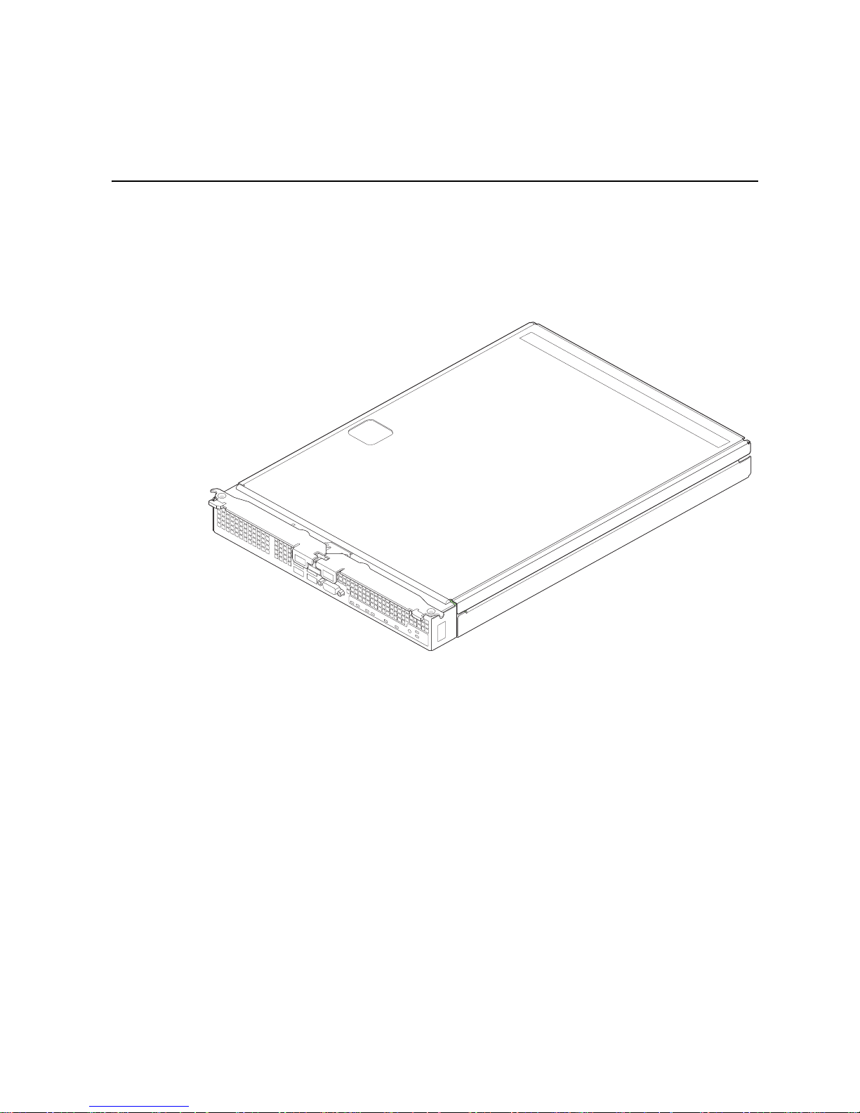
This chapter briefly describes the main features of the Intel® Compute Module
MFS5520VI, as well as provides illustrations showing the location of important
components and connections on the compute module.
®
The Intel
Compute Module MFS5520VI is shown in the following pictures.
Intel® Compute Module MFS5520VI User Guide 1
Figure 1. Intel
®
Compute Module MFS5520VI
Page 16
2 Intel® Compute Module MFS5520VI User Guide
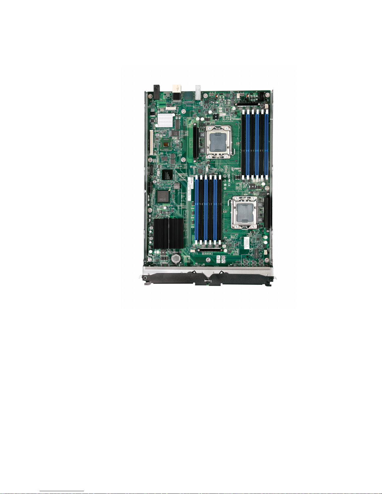
Figure 2. Server Board
Page 17

Feature Overview
The following table summarizes the major features of the compute module.
Table 1. Compute Module Features
Feature Description
Processor Support for one or two Intel® Xeon® Processors 5500 Series or two
®
Xeon® Processor 5600 Series in FC-LGA 1366 Socket B
Intel
package with up to 95 W Thermal Design Power (TDP)
• 4.8 GT/s, 5.86 GT/s and 6.4 GT/s Intel
(Intel
®
QPI)
®
QuickPath Interconnect
• Enterprise Voltage Regulator-Down (EVRD) 11.1
Memory • T w elve DIMMs across six memory channels (three channels per
processor)
• Support for 1066/1333-MT/s ECC registered (RDIMM) or
unbuffered (UDIMM) DDR3 memory
Chipset
Video On-board ServerEngines* LLC Pilot II Controller
• Intel
• Intel
®
5520 Chipset I/O Hub
®
82801Jx I/O Controller Hub
• Integrated 2D Video Controller
• 32 MB DDR2 Memory
LAN One 10/100/1000 Intel® 82575 Gigabit Ethernet Controller
Hard Drive LSI* 1064e SAS Controller
Server Management On-board ServerEngines* LLC Pilot II Controller
• Integrated Baseboard Management Controller (Integrated
BMC), IPMI 2.0 compliant
• Integrated Super I/O on LPC interface
Intel® Compute Module MFS5520VI User Guide 3
Page 18
Connector and Component Locations
AF003077
J
Q
F
B
G
H
P
O
N
L
M
A
C
E
D
I
K
M
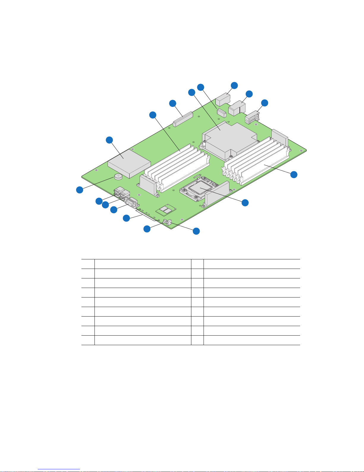
AIntel® 5520 Chipset I/O Hub J CPU 2 Socket
B CPU2 DIMM Slots K Power/Fault LEDs
C Mezzanine Card Connector 1 L Power Switch
D CPU 1 with Heatsink M Activity and ID LEDs
E Mezzanine Card Connector 2 N Video Connector
F Midplane Power Connector O USB Ports 2 and 3
G Midplane Signal Connector P USB Ports 0 and 1
H Midplane Guide Pin Receptacle Q CMOS Battery
I CPU 1 DIMM Slots
4 Intel® Compute Module MFS5520VI User Guide
Figure 3. Component and Connector Locations
Page 19
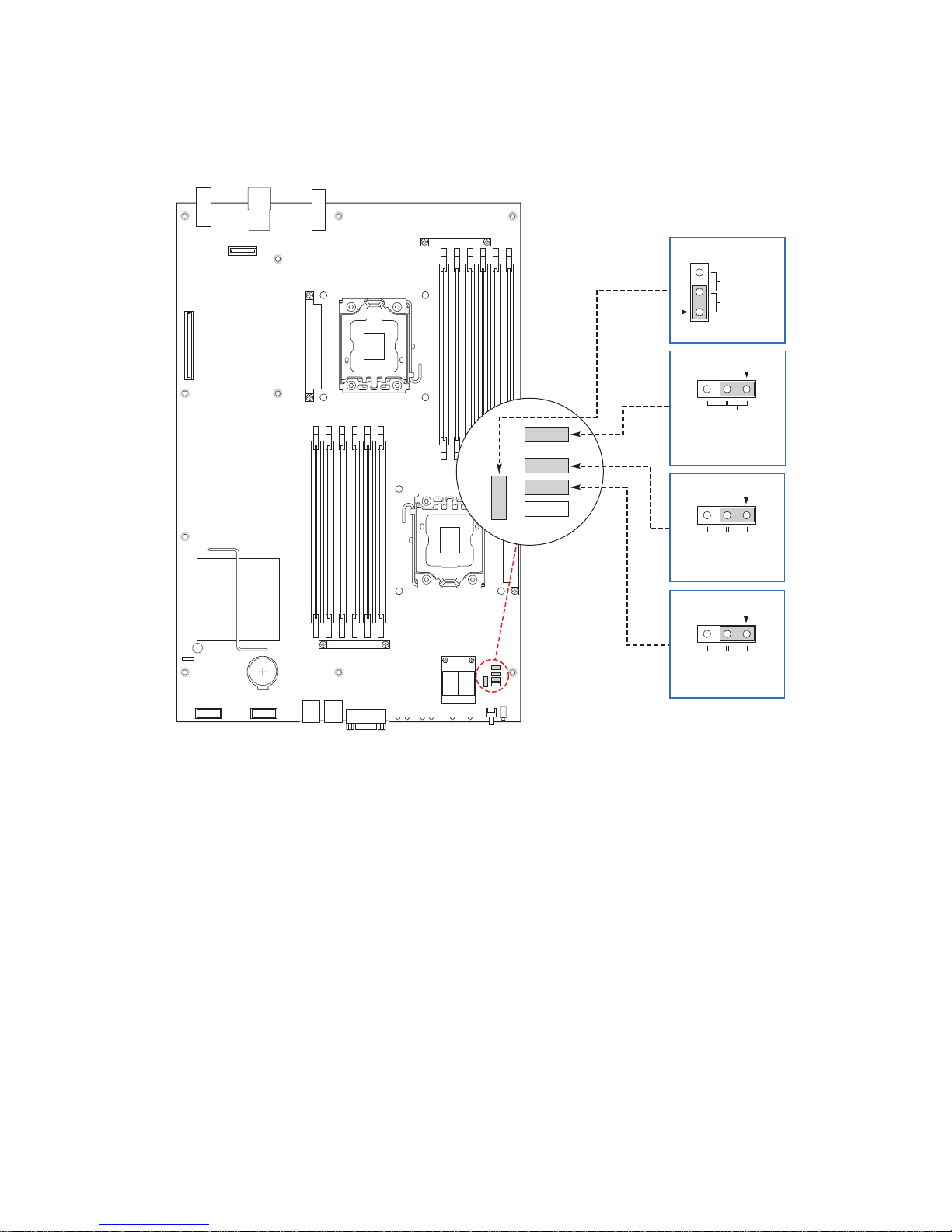
Configuration Jumpers
BMC Force Update
J9A5
3
2
Default
Disabled
Enabled
CMOS Clear
J9A4
3
2
Default
Clear
CMOS
32
PASSWORD Clear
DefaultClear
Password
J9A3
AF003078
3
2
BIOS Recover
Default
Boot from
Emergency
BIOS Image
J9B9
Figure 4. Configuration Jumper Locations
Intel® Compute Module MFS5520VI User Guide 5
Page 20

Table 2. Configuration Jumper Description
Jumper Name Pins What happens at reset…
J9B9: BIOS
Recover
J9A3: Password
Clear
J9A4: CMOS
Clear
J9A5: BMC Force
Update
1-2 These pins should have a jumper in place for normal operation.
(Default)
2-3 If these pins are jumpered, the compute module boots from the
emergency BIOS image. These pins should not be jumpered for
normal operation.
1-2 These pins should have a jumper in place for normal operation
(Default)
2-3 If these pins are jumpered, administrator and user passwords are
cleared immediately. These pins should not be jumpered for normal
operation.
1-2 These pins should have a jumper in place for normal operation.
(Default)
2-3 If these pins are jumpered, the CMOS setti n gs are cleared
immediately. These pins should not be jumpered for normal
operation.
To clear the CMOS, you must only momentarily move the jumper to
position 2-3 . You must then move the jumper back to the default
position 1-2 and reinstall the compute module into the chassis.
1-2 BMC Firmware Force Update Mode - Disabled (Default)
2-3 BMC Firmware Force Update Mode - Enabled
6 Intel® Compute Module MFS5520VI User Guide
Page 21
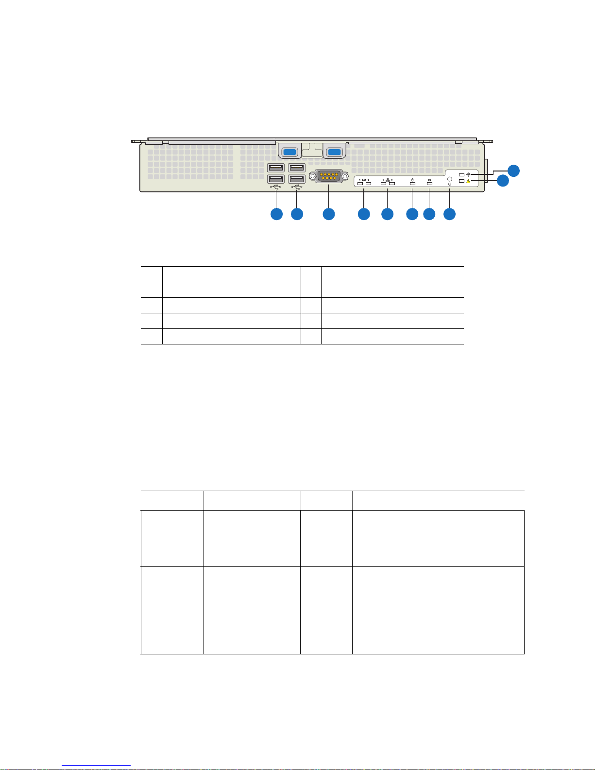
Front Panel Connectors and Indicators
B
A
A USB Ports 0 and 1 B USB2 Ports 2 and 3
C Video Connector D I/O 1 and I/O 2 Activity LEDs
E NIC1 and NIC2 Activity LEDs F Drive Activity LED
G ID LED H Power Button
I Fault LED J Power LED
Figure 5. Front Panel Connectors and Indicators
J
I
C
D
F
E
G
H
AF003079
Front Panel Indicators
The Intel® Compute Module MFS5520VI includes a number of diagnostic LEDs on the
front of the compute module to aid in troubleshooting. The following table lists these
LEDs along with a usage description of each LED.
Table 3. Diagnostic LED Information
LED Name Function Color Indicator
Power LED Identifies power state
of compute module
Fault LED Identifies fault warning Amber Off = No Fault
Green Off = Power is off
On = Power on
Slow Blink = Power is in standby or
sleeping mode
On = Critical error or non-recoverable
Slow blink = Non-critical
Fast blink = Locate (when de vice does not
have an ID LED)
Double blink = Degraded state
Intel® Compute Module MFS5520VI User Guide 7
Page 22

Table 3. Diagnostic LED Information
LED Name Function Color Indicator
ID LED Provides an aid in
identifying a compute
module from the front
panel
Drive activity
LED
NIC1—2
LEDs
I/O 1 - I/O 2
Activity LEDs
Indicates drive activity Green Off = No drive activity
Indicates network
activity and link
Indicates network
activity and link of
NICs on I/O
mezzanine card
Hardware Requirements
To avoid integration difficulties and possible board damage, your server compute module
must meet the requirements outlined below.
Processor
The Intel® Compute Module MFS5520VI supports up to two Intel® Xeon® Processors
5500 series or two Intel
package with up to 95-W Thermal Design Power (TDP):
• 4.8 GT/s, 5.86 GT/s and 6.4 GT/s Intel
Blue Use the Intel® Modular Server Control
software to activate or inactivate the LED.
Blink = Drive activity
Green Blink = Outbound activity
Green Off = No link
On = Link established
Blink = Activity
®
Xeon® Processor 5600 series in FC-LGA 1366 Socket B
®
QuickPath Interconnect (Intel® QPI)
• Enterprise Voltage Regulator-Down (EVRD) 11.1
Memory
The Intel® Compute Module MFS5520VI supports six DDR3 memory channnels (three
per processor socket) with two DIMMs per channel, thereby supporting up to 12 DIMMs
with dual-processor sockets.
The compute module supports DDR3 1066 and DDR3 1333 memory technologies and
supports both registered DIMMs (RDIMMs) and unbuffered DIMMs (UDIMMs).
RDIMMs must be ECC only, while UDIMMs can be ECC or non-ECC.
8 Intel® Compute Module MFS5520VI User Guide
Page 23

Power Supply
A minimum of one 1000-Watt power supply is required to turn on a compute module.
One power supply supports one compute module plus all other modules in the chassis.
Two power supplies support two to three compute modules (in any slot) plus all other
modules in the chassis.
Three power supplies support four to six compute modules (in any slot) plus all other
modules in the chassis.
Any additional power supplies above the minimum required (based on configuration)
provide redundancy.
Intel® Compute Module MFS5520VI User Guide 9
Page 24

Additional Information and Software
If you need more information about this product or information about the modular server
systems that can be used with the compute module, use the following resources.
For this information
or software
If you just received
this product and you
need to install
components in your
compute module
For in-depth technical
information about the
compute module,
including chipset
information and
mechanical drawings
If you just received
this product and you
need to assemble
your modular server
system and install
components
For in-depth technical
information about the
modular server
system, including
subsystem overviews
and mechanical
drawings
Use this Document or Software
®
Compute Module MFS5520VI Quick Start User’s Guide
Intel
Available in the product box or for download at:
http://www.intel.com/support/motherboards/server/mfs5520vi/
®
Intel
Compute Module MFS5520VI Technical Product
Specification
Available at:
http://www.intel.com/support/motherboards/server/mfs5520vi/
®
Intel
Modular Server System MFSYS25/MFSYS35 Quick Start
User's Guide
Available in the product box or for download at:
http://www.intel.com/support/motherboards/server/mfsys25/
Intel®Modular Server System MFSYS25/MFSYS35 User's
Guide
Available at:
http://www.intel.com/support/motherboards/server/mfsys25/
®
Intel
Modular Server System MFSYS25/MFSYS35 Technical
Product Specification
Available at:
http://www.intel.com/support/motherboards/server/mfsys25/
Accessories or other
Intel server products
10 Intel® Compute Module MFS5520VI User Guide
Spares, Parts List, and Configuration Guide
Available at:
http://www.intel.com/support/motherboards/server/mfs5520vi/
or by using the Server Configurator Tool
Available at:
http://serverconfigurator.intel.com/default.aspx
Page 25

For this information
or software
Use this Document or Software
Hardware (peripheral
boards, adapter
cards) and operating
systems that have
been tested with this
product
Processors that have
been tested with this
product
DIMMs that have
been tested with this
product
Hard Drives that have
been tested with this
product
Latest drivers, Unified
Firmware Update
packages and utilities
For software to
manage your Intel
®
Modular Server
System
Tested Product Lists
Av a ilable at:
http://www.intel.com/support/motherboards/server/mfs5520vi/
or by using Server Configurator Tool
Av a ilable at:
http://serverconfigurator.intel.com/default.aspx
Available for download at:
http://www.intel.com/support/motherboards/server/mfs5520vi/
Click the "Software and Drivers" link on the left side of the web
page.
®
Modular Server Control UI
Intel
The Intel® Management Module integrated management
interface for the modular server system. For instructions and
information refer to the Intel® Modular Server System
MFSYS25/MFSYS35 User Guide
Av a ilable at:
http://www.intel.com/support/motherboards/server/mfsys25/
®
Intel
System Management Software
Av a ilable at:
http://www.intel.com/go/servermanagement/
Intel® Compute Module MFS5520VI User Guide 11
Page 26

12 Intel® Compute Module MFS5520VI User Guide
Page 27

2 Hardware Installations and Upgrades
Before You Begin
Before working with your server product, review the safety and ESD information at the
beginning of this manual and in the appendices.
Tools and Supplies Needed
• Phillips
*
(cross head) screwdriver (#1 bit and #2 bit)
• 1/4-inch nut driver
• Anti-static wrist strap and conductive foam pad (recommended)
Installation Guidelines
Before installing options:
1. Observe the safety and ESD information at the beginning of this manual and in the
appendices.
2. Remove the compute module from the chassis. Before doing so, you must first shut
down the operating system and turn off the compute module.
3. Take note of the following color coding on components:
— Blue on a component indicates a touch point, where you can grip the component
to install or remove it from the server.
— Green on a component indicates that the component may be hot-swapped. For a
complete list of installation or removal steps, see the instructions included with
the hot-swap component.
Removing and Installing an Intel® Compute Module MFS5520VI
Removing a Compute Module from the Chassis
To remove a compute module from the chassis, follow these steps:
1. Observe the safety and ESD information at the beginning of this manual and in the
appendices.
2. If the compute module is operating, shut down the operating system and power it
down.
3. Release the two retention levers by pressing on the release button located between
the two lever handles.
Intel® Compute Module MFS5520VI User Guide 13
Page 28

4. Rotate the two lever handles outward and pull the compute module from the chassis
slot.
5. Place either a filler or another compute module into the bay within one minute. This
step is required to maintain proper airflow patterns throughout the chassis and to
ensure proper chassis cooling.
Installing a Compute Module into the Chassis
To install a compute module into the chassis, follow these steps:
1. Observe the safety and ESD information at the beginning of this manual and in the
appendices.
2. If you have not done so already, install any necessary options, such as processors,
memory, hard drives and expansion cards in the compute module.
Note: The top cover is a required component of the compute module; do not attempt
to insert a compute module into a chassis without a top cover installed.
3. Make sure the retention levers on the compute module are in the open position.
4. Insert the compute module into an open slot in the chassis and slide it in until it
stops.
5. Close the retention lever handles on the front of the compute module.
Removing or Installing the Top Cover
Removing the Top Cover
To remove the top cover, follow these steps:
1. Observe the safety and ESD information at the beginning of this manual and in the
appendices.
2. If the compute module is installed in a chassis, remove it. For instructions, see
“Removing a Compute Module from the Chassis” on page 13.
3. Carefully lay the compute module down on a flat, non-conductive surface, with the
cover side up.
14 Intel® Compute Module MFS5520VI User Guide
Page 29
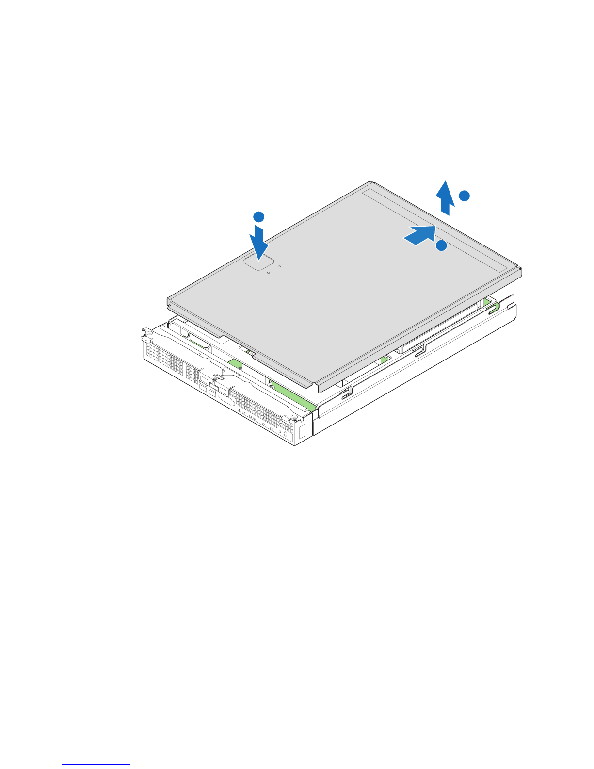
4. Press the top cover release button (see letter “A” in Figure 6) and slide the top cover
1 I/O 2
ID
1 2
AF003088
A
B
C
back, away from the compute module bezel (see letter “B” in Figure 6).
5. Lift the top cover up and off the compute module (see letter “C” in Figure 6) .
Caution: Always install the top cover before installing the compute module into a
chassis.
Figure 6. Removing Top Cover
Intel® Compute Module MFS5520VI User Guide 15
Page 30

Installing the Top Cover
To install the top cover, follow these steps:
1. Observe the safety and ESD information at the beginning of this manual and in the
appendices.
2. Place the top cover on the compute module so that it engages the cover guide
notches (see letter “A” in Figure 7).
Note: Before closing the top cover, check that all components are installed and
seated correctly and that no loose tools or parts are inside the compute
module.
3. Slide the top cover forward to the closed position until the retention latch fully
engages (see letter “B” in Figure 7).
A
B
16 Intel® Compute Module MFS5520VI User Guide
1 I/O 2
1 2
ID
Figure 7. Installing Top Cover
AF003089
Page 31

Installing or Replacing a Processor
Caution: Processor must be appropriate: You may damage the compute module if you install an
inappropriate processor.
Caution: ESD and handling processors: Reduce the risk of electrostatic discharge (ESD) damage to
the processor by doing the following: (1) Touch the metal chassis before touching the
processor or compute module. Keep part of your body in contact with the metal chassis to
dissipate the static charge while handling the processor. (2) Avoid moving around
unnecessarily.
Caution: Protective socket cover needs to be removed for proper cooling of the processor; failure to
remove the cover could result in damage to the compute module.
Installing a Processor
To install a processor, follow these steps:
1. Observe the safety and ESD information at the beginning of this manual and in the
appendices.
Removing Components
2. If the compute module is installed in a chassis, remove it. For instructions, see
“Removing a Compute Module from the Chassis” on page 13.
3. Remove the top cover. For instructions, see “Removing the Top Cover” on page 14.
Intel® Compute Module MFS5520VI User Guide 17
Page 32
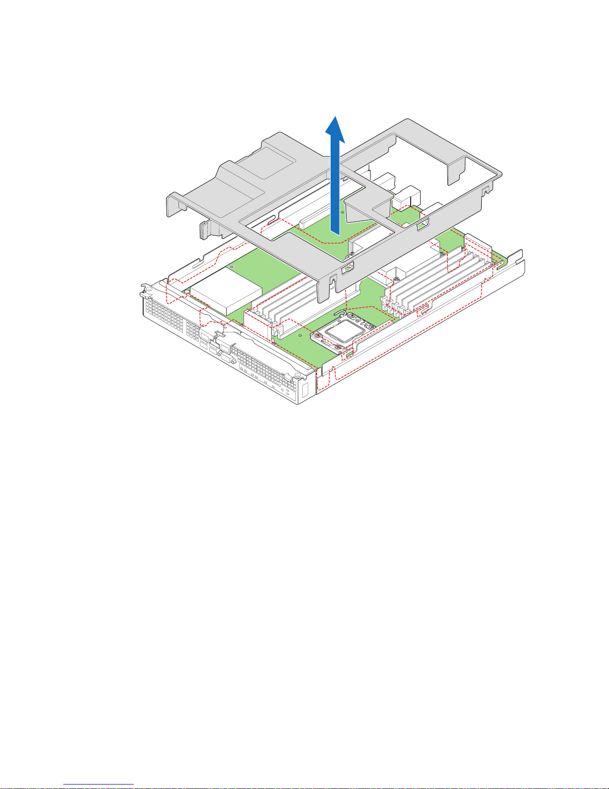
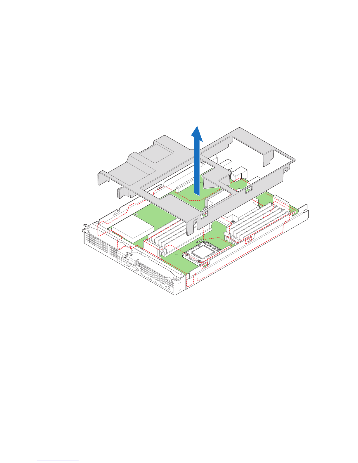
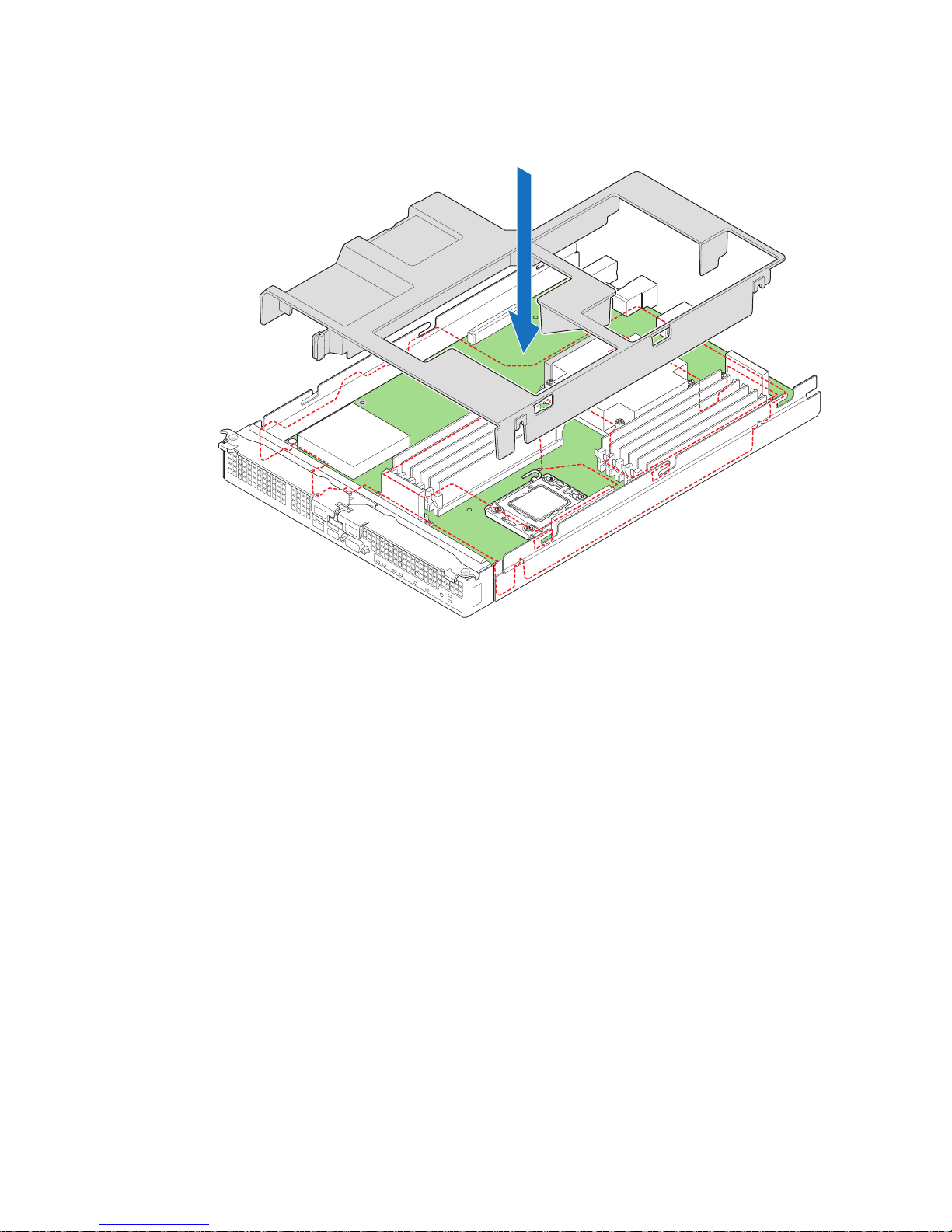
4. Remove the processor air duct (see Figure 8).
1 I/O 2
ID
1 2
AF003080
Figure 8. Removing Processor Air Duct
18 Intel® Compute Module MFS5520VI User Guide
Page 33
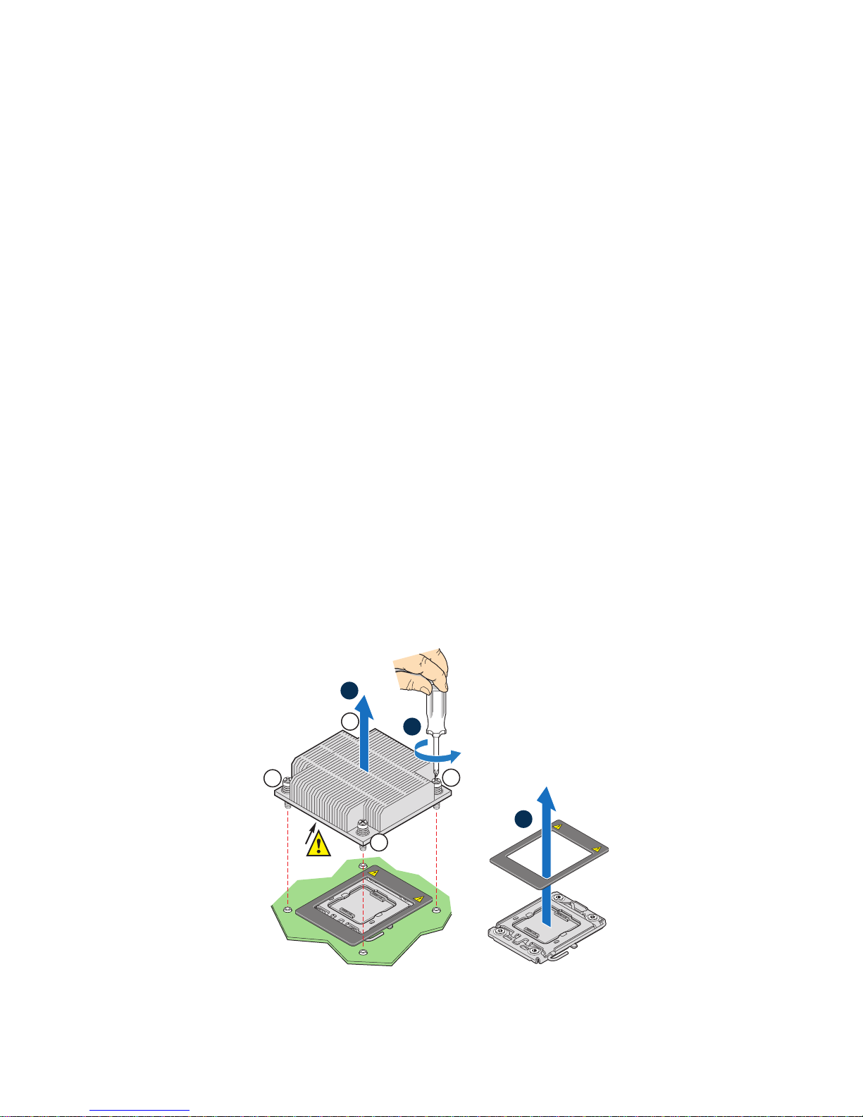
Removing the Heatsink
Caution: Improper removal can damage the heatsink. Pay close attention to the steps and perform
each step exactly as indicated to avoid damage.
Note: This procedure assumes that you are removing the heatsink for the first time.
Note: If you are installing only a single processor on your server board, do not remove the
heatsink and spacer over the second processor.
5. Loosen the four captive screws on the heatsink corners in a diagonal manner
according to the numbers shown in Figure 9 as follows:
a. Starting with the screw at location 1, loosen it by giving it two rotations in the
anticlockwise direction (see letter “A” in Figure 9) and stop. (IMPORTANT:
Do not fully loosen.)
b. Proceed to the screw at location 2 and loosen it by giving it two rotations and
stop.
c. Loosen screws at locations 3 and 4 by giving each screw two rotations and then
stop.
d. Repeat steps 5a through 5c by giving each screw two rotations each time until
all screws are loosened.
6. Lift the heatsink from the board (see letter “B” in Figure 9).
7. Remove and discard the spacer (see letter “C” in Figure 9).
Note: The system is shipped with a spacer installed between the heatsink and the processor
socket to protect the socket protective cover. This spacer will need to be removed and
discarded before installing the processor.
B
3
2
TIM
Discard to Install CPU
4
This Side Up
A
1
C
This Side Up
Discard to Install CPU
AF003161
Intel® Compute Module MFS5520VI User Guide 19
Figure 9. Removing the Heatsink
Page 34
Installing the Processor
AF002836
B
A
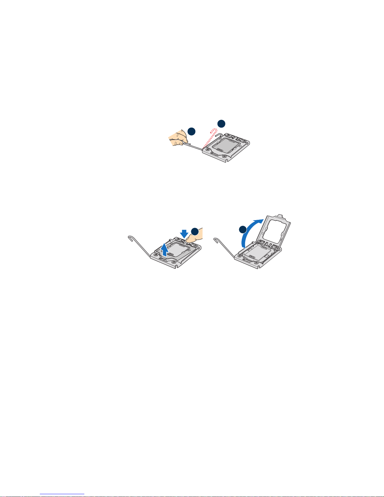
8. Locate the processor socket.
9. Push the lever handle down and away from the socket to release it (see letter “A” in
Figure 10).
10. Rotate the lever open all the way (see letter “B” in Figure 10).
A
B
AF002835
Figure 10. Lifting the Processor Socket Lever
11. Push the rear tab with your finger tip to bring the front end of the load plate open
slightly (see letter “A” in Figure 11).
12. Open the load plate (see letter “B” in Figure 11).
Figure 11. Opening the Load Plate
13. Remove the protective socket cover (see Figure 12).
Note: Do not touch the socket pins; they are very sensitive and easily damaged.
Note: Retain the protective socket cover for use when removing a processor that will not be
replaced.
20 Intel® Compute Module MFS5520VI User Guide
Page 35

AF002837
AF002838
Figure 12. Removing the Protective Socket Cover
14. Remove the processor from the packaging box and remove the protective shipping
cover (see Figure 13).
Figure 13. Removing the Processor Protective Cover
15. Orient the processor with the socket so that the processor cutouts match the two
socket pins, and insert the processor into the socket (see Figure 14).
Intel® Compute Module MFS5520VI User Guide 21
Page 36

A
A
B
AF002840
AF002839
Figure 14. Installing the Processor
Note: Make sure the alignment triangle mark and the alignment triangle cutout align correctly.
16. Close the CPU load plate all the way (see letter “A” in Figure 15).
17. Close the socket lever completely and ensure that the load plate tab engages under
the socket lever when fully closed (see letter “B” in Figure 15).
Installing the Heatsink
Caution: Improper installation can damage the heatsink. Pay close attention to the steps and
perform each step exactly as indicated to avoid damage.
Caution: The heatsink has Thermal Interface Material (TIM) located on the bottom of it. Use
caution when you unpack the heatsink so you do not damage the TIM.
Note: New unused heatsinks have adequate TIM on the bottom. If you are reusing a heatsink
from replacing a processor, make sure there is adequate TIM present on the heatsink to
support processor cooling.
18. Remove the protective film on the TIM, if present.
19. Orient the heatsink over the processor as shown in Figure 16. The heatsink fins must
be positioned as shown to provide correct airflow through the system. Airflow goes
from front-to-back of the compute module.
22 Intel® Compute Module MFS5520VI User Guide
Figure 15. Closing the Load Plate
Page 37

Note: Figure 16 illustrates the heatsink orientation for CPU 1. The heatsink over CPU 2 should
be oriented in a reverse direction so as to provide correct airflow through the compute
module.
20. Set the heatsink over the processor, lining up the four captive screws with the four
posts surrounding the processor.
21. Loosely screw in the captive screws on the heatsink corners in a diagonal manner
according to the numbers shown in Figure 16 as follows:
a. Starting with the screw at location 1, engage the screw threads by giving it two
rotations in the clockwise direction and stop. (IMPORTANT: Do not fully
tighten.)
b. Proceed to the screw at location 2 and engage the screw threads by giving it two
rotations and stop.
c. Engage screws at locations 3 and 4 by giving each screw two rotations and then
stop.
d. Repeat steps 21a through 21c by giving each screw two rotations each time until
all screws are lightly tightened upto a maximum of 8 inch-lbs torque.
2
TIM
Compute Module Front
Figure 16. Installing the Heatsink
Reinstalling components
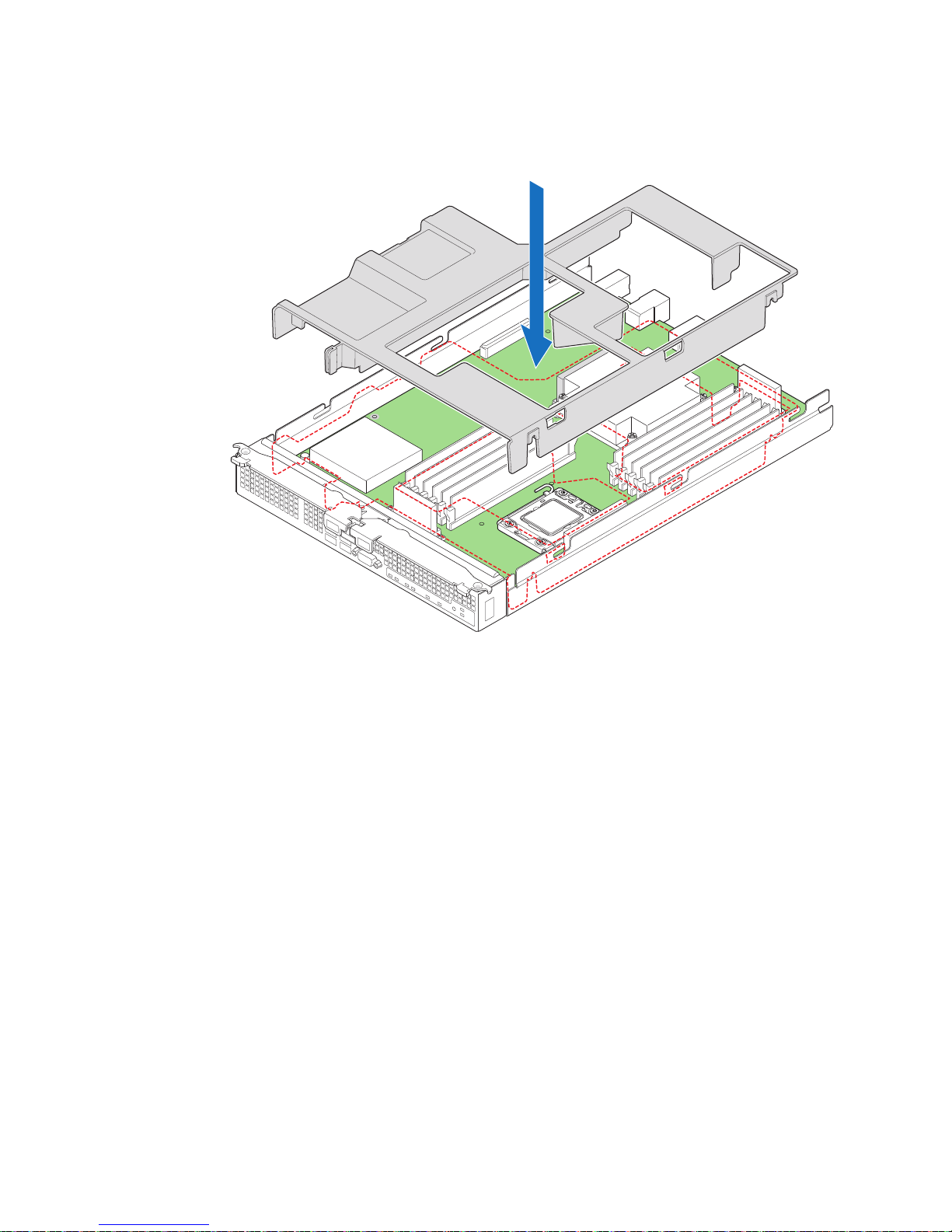
22. Reinstall the processor air duct.
3
Air Flow
1
4
CPU 1 Socket
AF003122
Intel® Compute Module MFS5520VI User Guide 23
Page 38

Figure 17. Reinstalling Processor Air Duct
1 I/O 2
ID
1 2
AF003080
23. Reinstall the top cover. For instructions, see “Installing the Top Cover” on page 16.
24. Reinstall the server compute module in the chassis. For instructions, see “Installing
a Compute Module into the Chassis” on page 14.
24 Intel® Compute Module MFS5520VI User Guide
Page 39

Replacing a Processor
To replace a processor, follow these steps:
1. Observe the safety and ESD information at the beginning of this manual and in the
appendices.
Removing Components
2. If the compute module is installed in a chassis, remove it. For instructions, see
“Removing a Compute Module from the Chassis” on page 13.
3. Remove the top cover. For instructions, see “Removing the Top Cover” on page 14.
4. Remove the processor air duct (see Figure 18).
Intel® Compute Module MFS5520VI User Guide 25
1 I/O 2
1 2
ID
Figure 18. Removing Processor Air Duct
AF003080
Page 40

Removing the Heatsink
2
3
1
4
TIM
Air Flow
AF003123
A
B
5. Loosen the four captive screws on the heatsink corners in a diagonal manner
according to the numbers shown in Figure 19 as follows:
a. Starting with the screw at location 1, loosen it by giving it two rotations in the
anticlockwise direction (see letter “A” in Figure 19) and stop. (IMPORTANT:
Do not fully loosen.)
b. Proceed to the screw at location 2 and loosen it by giving it two rotations and
stop.
c. Loosen screws at locations 3 and 4 by giving each screw two rotations and then
stop.
d. Repeat steps 5a through 5c by giving each screw two rotations each time until
all screws are loosened.
6. Twist the heatsink slightly to break the seal between the heatsink and the processor.
7. Lift the heatsink from the processor (see letter “B” in Figure 19). If it does not pull
up easily, twist the heatsink again. Do not force the heatsink from the processor.
Doing so could damage the processor.
26 Intel® Compute Module MFS5520VI User Guide
Removing the Old Processor
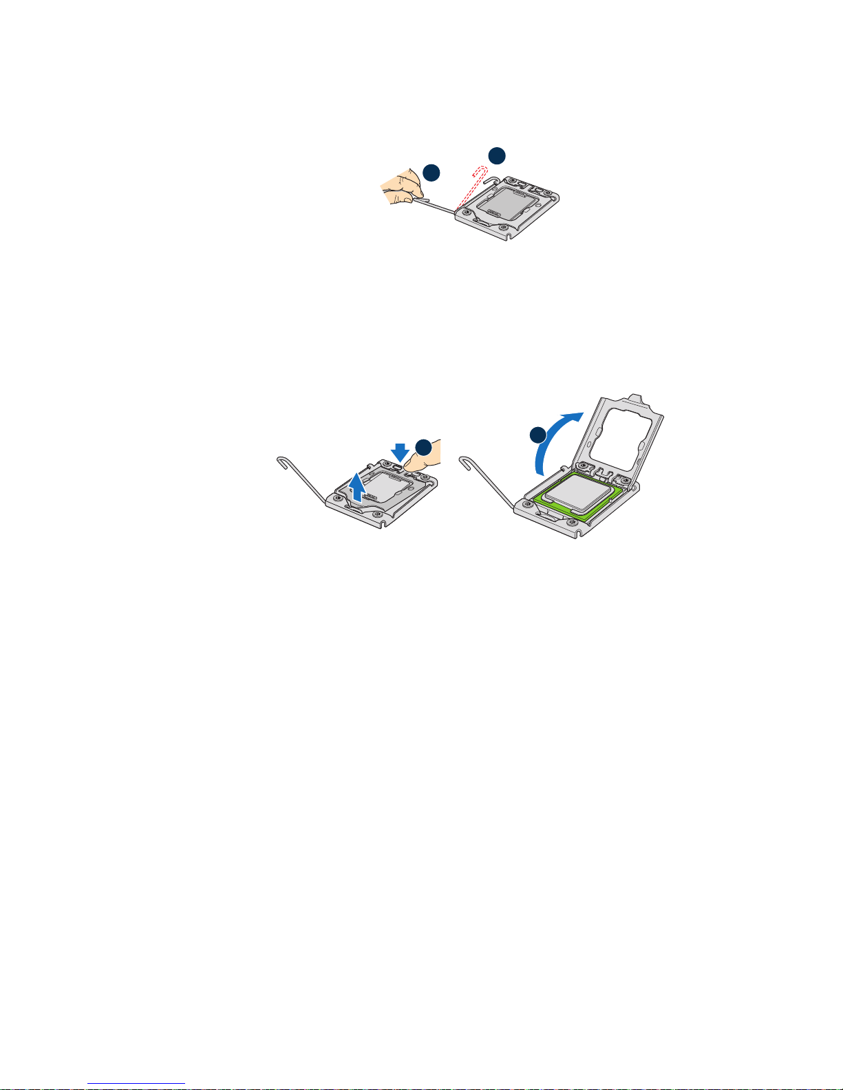
8. Push the lever handle down and away from the socket to release it (see letter “A” in
Figure 20).
9. Rotate the lever open all the way (see letter “B” in Figure 20).
Figure 19. Removing the Heatsink
Page 41
A
AF003096
A
B
B
AF002835
Figure 20. Lifting Processor Socket Handle
10. Push the rear tab with your finger tip to bring the front end of the load plate open
slightly (see letter “A” in Figure 21).
11. Open the load plate (see letter “B” in Figure 21).
Figure 21. Opening the Load Plate
12. Remove the processor.
Note: Do not touch the socket pins; they are very sensitive and easily damaged.
Intel® Compute Module MFS5520VI User Guide 27
Page 42

A
Figure 22. Removing the Processor
AF003097
28 Intel® Compute Module MFS5520VI User Guide
Page 43

Installing the Replacement Processor
AF002838
13. If present, remove the protective shipping cover from the replacement processor.
Figure 23. Removing Protective Shipping Cover
14. Orient the replacement processor with the processor socket so that the processor
cutouts match the socket notches. Install the replacement processor (see Figure 24).
Caution: The underside of the processor has components that may damage the
socket pins if installed improperly. Processor must align correctly with
socket opening before installation. DO NOT DROP processor into socket.
A
AF002839
Figure 24. Orienting and Installing Processor
15. Close the processor load plate (see letter “A” in Figure 25).
16. Close the socket lever completely and ensure that the load plate tab engages under
the socket lever when fully closed (see letter “B” in Figure 25).
Intel® Compute Module MFS5520VI User Guide 29
Page 44

Figure 25. Closing the Load Plate and Socket Lever
A
B
AF002840
Installing the Heatsink
Caution: Improper installation can damage the heatsink. Pay close attention to the steps and
perform each step exactly as indicated to avoid damage.
Caution: The heatsink has Thermal Interface Material (TIM) located on the bottom of it. Use
caution when you unpack the heatsink so you do not damage the TIM.
Note: New unused heatsinks have adequate TIM on the bottom. If you are reusing a heatsink
from replacing a processor, make sure there is adequate TIM present on the heatsink to
support processor cooling.
17. Remove the protective film on the TIM, if present.
18. Orient the heatsink over the processor as shown in Figure 26. The heatsink fins must
be positioned as shown to provide correct airflow through the system. Airflow goes
from front-to-back of the compute module.
Note: Figure 26 illustrates the heatsink orientation for CPU 1. The heatsink over CPU 2 should
be oriented in a reverse direction so as to provide correct airflow through the compute
module.
19. Set the heatsink over the processor, lining up the four captive screws with the four
posts surrounding the processor.
20. Loosely screw in the captive screws on the heatsink corners in a diagonal manner
according to the numbers shown in Figure 26 as follows:
a. Starting with the screw at location 1, engage the screw threads by giving it two
rotations in the clockwise direction and stop. (IMPORTANT: Do not fully
tighten.)
b. Proceed to the screw at location 2 and engage the screw threads by giving it two
rotations and stop.
c. Engage screws at locations 3 and 4 by giving each screw two rotations and then
stop.
d. Repeat steps 20a through 20c by giving each screw two rotations each time until
all screws are lightly tightened upto a maximum of 8 inch-lbs torque.
30 Intel® Compute Module MFS5520VI User Guide
Page 45

TIM
3
Air Flow
2
1
4
Front
CPU 1 Socket
AF002841
Figure 26. Reinstalling Heatsink
Intel® Compute Module MFS5520VI User Guide 31
Page 46

Reinstalling Components
1 I/O 2
ID
1 2
AF003080
21. Reinstall the processor air duct.
Figure 27. Reinstalling Processor Air Duct
22. Reinstall the top cover. For instructions, see “Installing the Top Cover” on page 16.
23. Reinstall the server compute module in the chassis. For instructions, see “Installing
a Compute Module into the Chassis” on page 14.
32 Intel® Compute Module MFS5520VI User Guide
Page 47

Installing and Removing Memory Modules
Supported Memory
The compute module provides support for up to twelve DIMMs across six memory
channels (three channels per processor).
DIMMs must be populated in pairs across consecutive channels starting with the lowest
numbered slot in each channel.
Memory Map and Population Rules
The nomenclature for DIMM sockets implemented on the Intel® Compute Module
MFS5520VI is detailed in the following figure.
Processor Socket 1 Processor Socket 2
Channel A Channel B Channel C Channel D Channel E Channel F
A1 A2 B1 B2 C1 C2 D1 D2 E1 E2 F1 F2
Figure 28. DIMM Nomenclature
The following general rules must be observed when selecting and configuring memory to
obtain the best performance from the compute module.
• Mixing RDIMMs and UDIMMs is not supported.
• DIMMs are organized into physical slots on DDR3 memory channels that belong to
processor sockets.
• The memory channels from processor socket 1 are identified as Channel A, B, and C.
The memory channels from processor socket 2 are identified as Channel D, E, and F.
• The DIMM slot identifiers on the compute module Quick Reference Label provide
information about the channel, and therefore the processor to which they belong. For
example, DIMM_A1 is the first DIMM slot on Channel A on processor 1; DIMM_D1
is the first DIMM socket on Channel D on processor 2.
• When CPU Socket 1 is empty, any DIMM memory in Channel A through Channel C
is unavailable.
• When CPU Socket 2 is empty, any DIMM memory in Channel D through Channel F
is unavailable.
• If both processor sockets are populated but Channel A through Channel C is empty,
the platform can still function with remote memory in Channel D through Channel F.
However, platform performance suffers latency due to remote memory.
• The memory operational mode is configurable at the channel level. Two modes are
supported: Independent Channel Mode and Mirrored Channel Mode.
Intel® Compute Module MFS5520VI User Guide 33
Page 48

• The memory slots of each DDR3 channel from the Intel
series or Intel
This holds true even for the Independent Channel mode. Therefore, if A1 is empty, A2
cannot be populated or used.
®
Xeon® Processor 5600 series are populated on a farthest first fashion.
®
Xeon® processor 5500
• The BIOS selects the Independent Channel mode by default, which enables all
installed memory on all channels simultaneously.
• Mirrored Channel mode is not available when only one processor is populated (CPU
Socket 1).
• If both processor sockets are populated and the installed DIMMs are associated with
both processor sockets, then a given RAS mode is selected only if both the processor
sockets are populated to conform to that mode.
• The minimum memory population possible is one DIMM in slot A1. In this
configuration, the compute module operates in the Independent Channel mode; RAS
is not available.
• If both processor sockets are populated, the next upgrade from the Single Channel
mode installs DIMM_D1. This configuration results in an optimal memory thermal
spread, as well as Non-Uniform Memory Architecture (NUMA) aware interleaving.
The BIOS selects the Independent Channel mode of operation.
• If only one processor socket is populated, the next upgrade from the Single Channel
mode is installing DIMM_B1 to allow channel interleaving. The compute module
operates in the Independent Channel mode.
• If an installed DDR3 DIMM has faulty or incompatible SPD data, it is ignored during
memory initialization and is (essentially) disabled by the BIOS. If a DDR3 DIMM has
no SPD data or is missing SPD information, the slot in which it is placed is treated as
empty by the BIOS.
• The DIMM parameter matching requirements for memory RAS is local to a socket.
For example, while Channels A/B/C can have one match of timing, technology, and
size, Channels D/E/F can have a different set of parameters and RAS still functions.
• DDR3 DIMMs on adjacent slots on the same channel do not need to be identical.
• For the Mirrored Channel mode, the memory in Channels A and B of Socket 1 must
be identical and Channel C should be empty. Similarly, the memory in Channels D
and E of Socket 2 must be identical and Channel F should be empty.
— The minimum population upgrade for the Mirrored Channel mode is DIMM_A1,
DIMM_B1, DIMM_D1, and DIMM_E1 with both processor sockets populated.
DIMM_A1 and DIMM_B1 as a pair must be identical, and so must DIMM_D1
and DIMM_E1, but the DIMMs on different processor sockets do not need to be
identical. Failing to comply with these rules results in a switch back to the
Independent Channel mode.
— If Mirrored Channel mode is selected and the third channel of each processor
socket is not empty, the BIOS disables the memory in the third channel of each
processor socket.
34 Intel® Compute Module MFS5520VI User Guide
Page 49

• In the Mirrored Channel mode, both sockets must simultaneously satisfy the DIMM
matching rules on their respective adjacent channels. If the DDR3 DIMMs on
adjacent channels of a socket are not identical, the BIOS configures both the
processor sockets to default to the Independent Channel mode. If DIMM_D1 and
DIMM_E1 are not identical, then the compute module switches to the Independent
Channel Mode.
Installing DIMMs
DIMM slots are numbered as follows:
DIMM B2
DIMM A1
DIMM A2
DIMM B1
DIMM C2
DIMM C1
Intel® Compute Module MFS5520VI User Guide 35
DIMM F1
DIMM F2
DIMM E1
DIMM D2
DIMM D1
DIMM E2
Figure 29. DIMM Slot Order
AF003098
Page 50
To install DIMMs, follow these steps:
1 I/O 2
ID
1 2
AF003080
1. Observe the safety and ESD information at the beginning of this manual and in the
appendices.
2. If the compute module is installed in a chassis, remove it. For instructions, see
“Removing a Compute Module from the Chassis” on page 13.
3. Remove the top cover. For instructions, see “Removing the Top Cover” on page 14.
4. Remove the processor air duct (see Figure 30).
5. Locate the DIMM sockets.
6. Holding the DIMM by the edges, remove it from the package.
7. Make sure the clips at either end of the DIMM socket(s) are pushed outward to the
open position (see letter “A” in Figure 31).
8. Holding the DIMM by the edges, remove it from its anti-static package.
9. Position the DIMM above the socket. Align the notch on the bottom edge of the
DIMM with the key in the DIMM socket (see letter “B” in Figure 31 - the arrow is
pointing to the key in the socket).
10. Insert the bottom edge of the DIMM into the socket.
11. When the DIMM is correctly positioned, push down on the top edge of the DIMM
until the retaining clips snap into place (see letter “C” in Figure 31).
36 Intel® Compute Module MFS5520VI User Guide
Figure 30. Removing Processor Air Duct
Page 51

12. Make sure the clips are firmly in place (see letter “D” in Figure 31).
AF003099
D
A
B
E
C
DIMM B2
DIMM A1
DIMM A2
DIMM B1
DIMM C2
DIMM C1
DIMM F1
DIMM F2
DIMM E1
DIMM D2
DIMM D1
DIMM E2
Important: Visually check that each latch is fully closed and correctly engaged with
each DIMM edge slot (see letter “E” in Figure 31).
Figure 31. Installing DIMMs
13. Reinstall the processor air duct (see Figure 32).
Intel® Compute Module MFS5520VI User Guide 37
Page 52
14. Reinstall the top cover. For instructions, see “Installing the Top Cover” on page 16.
1 I/O 2
ID
1 2
AF003080
15. Reinstall the server compute module in the chassis. For instructions, see “Installing
a Compute Module into the Chassis” on page 14.
Removing DIMMs
To remove DIMMs, follow these steps:
1. Observe the safety and ESD information at the beginning of this manual and in the
appendices.
2. If the compute module is installed in a chassis, remove it. For instructions, see
“Removing a Compute Module from the Chassis” on page 13.
3. Remove the top cover. For instructions, see “Removing the Top Cover” on page 14.
Figure 32. Reinstalling Processor Air Duct
38 Intel® Compute Module MFS5520VI User Guide
Page 53

4. Remove the processor air duct (see Figure 33).
1 I/O 2
1 2
ID
AF003080
Figure 33. Removing Processor Air Duct
5. Locate the DIMM socket.
6. Gently open the retaining clips at each end of the socket (see letter “A” in Figure 34).
This slightly lifts the DIMM from its socket.
7. Holding the DIMM by the edges, remove it from the socket (see letter “B” in
Figure 34).
Intel® Compute Module MFS5520VI User Guide 39
Page 54

Important: Store the removed DIMM in an anti-static package.
DIMM B2
DIMM A1
DIMM A2
DIMM B1
DIMM C2
DIMM C1
E
B
D
A
DIMM F1
DIMM F2
DIMM E1
DIMM D2
DIMM D1
DIMM E2
AF003100
40 Intel® Compute Module MFS5520VI User Guide
Figure 34. Removing DIMMs
Page 55
8. Reinstall the processor air duct (see Figure 35).
1 I/O 2
1 2
ID
AF003080
Figure 35. Reinstalling Processor Air Duct
9. Reinstall the top cover. For instructions, see “Installing the Top Cover” on page 16.
10. Reinstall the server compute module in the chassis. For instructions, see “Installing
a Compute Module into the Chassis” on page 14.
Intel® Compute Module MFS5520VI User Guide 41
Page 56

Installing and Removing Mezzanine Card
Installing the Mezzanine Card
To install the mezzanine card, follow these steps:
1. Observe the safety and ESD information at the beginning of this manual and in the
appendices.
2. If the compute module is installed in a chassis, remove it. For instructions, see
“Removing a Compute Module from the Chassis” on page 13.
3. Remove the top cover. For instructions, see “Removing the Top Cover” on page 14.
4. Holding the mezzanine card by its edges, remove it from the packaging.
5. Remove the protective connector cover from the mezzanine card.
6. Locate the mezzanine card connectors on the server board.
42 Intel® Compute Module MFS5520VI User Guide
Page 57

7. Using a Phillips* screwdriver, remove four screws from the server board
(see Figure 36).
1 I/O 2
1 2
ID
Figure 36. Removing Screws from Server Board
AF003090
Intel® Compute Module MFS5520VI User Guide 43
Page 58
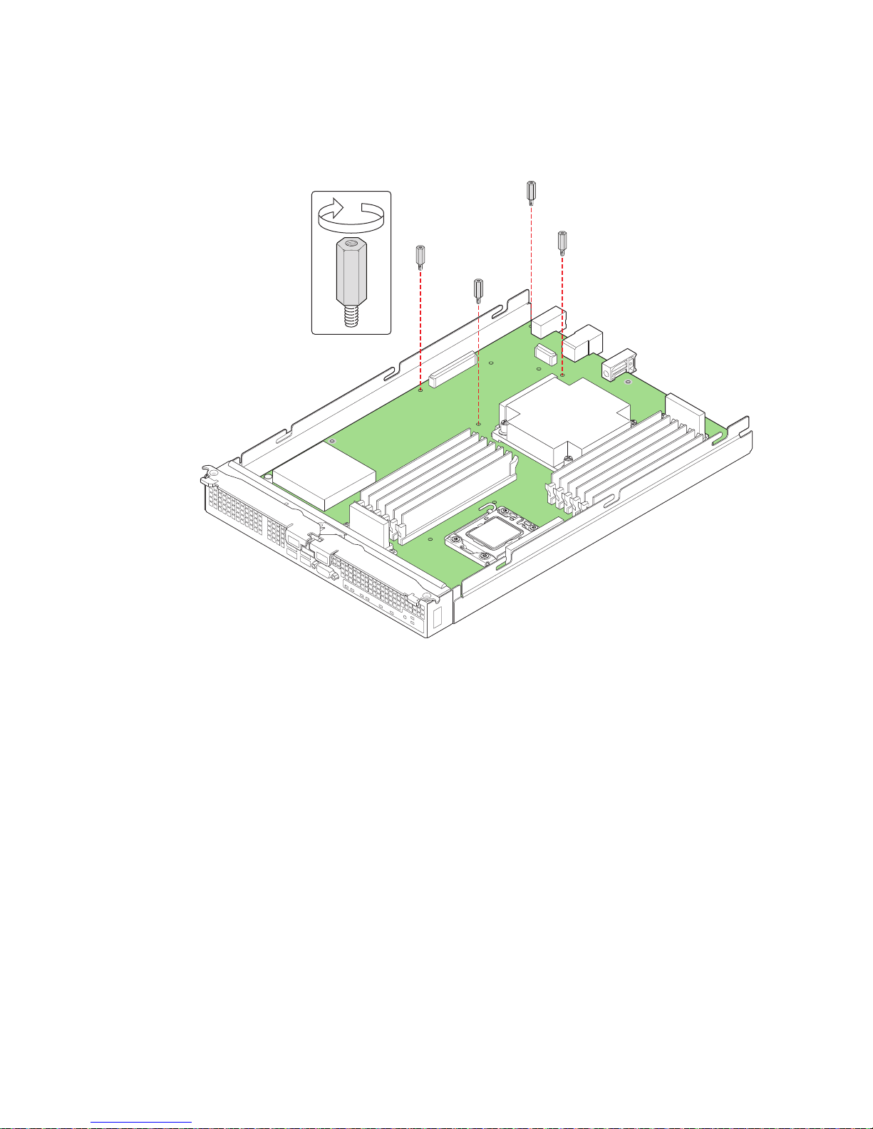
8. Using a 1/4-inch nut driver, install the four standoffs that shipped with the mezzanine
card (see Figure 37).
1 I/O 2
1 2
ID
Figure 37. Installing Standoffs for Mezzanine Card
AF003082
44 Intel® Compute Module MFS5520VI User Guide
Page 59
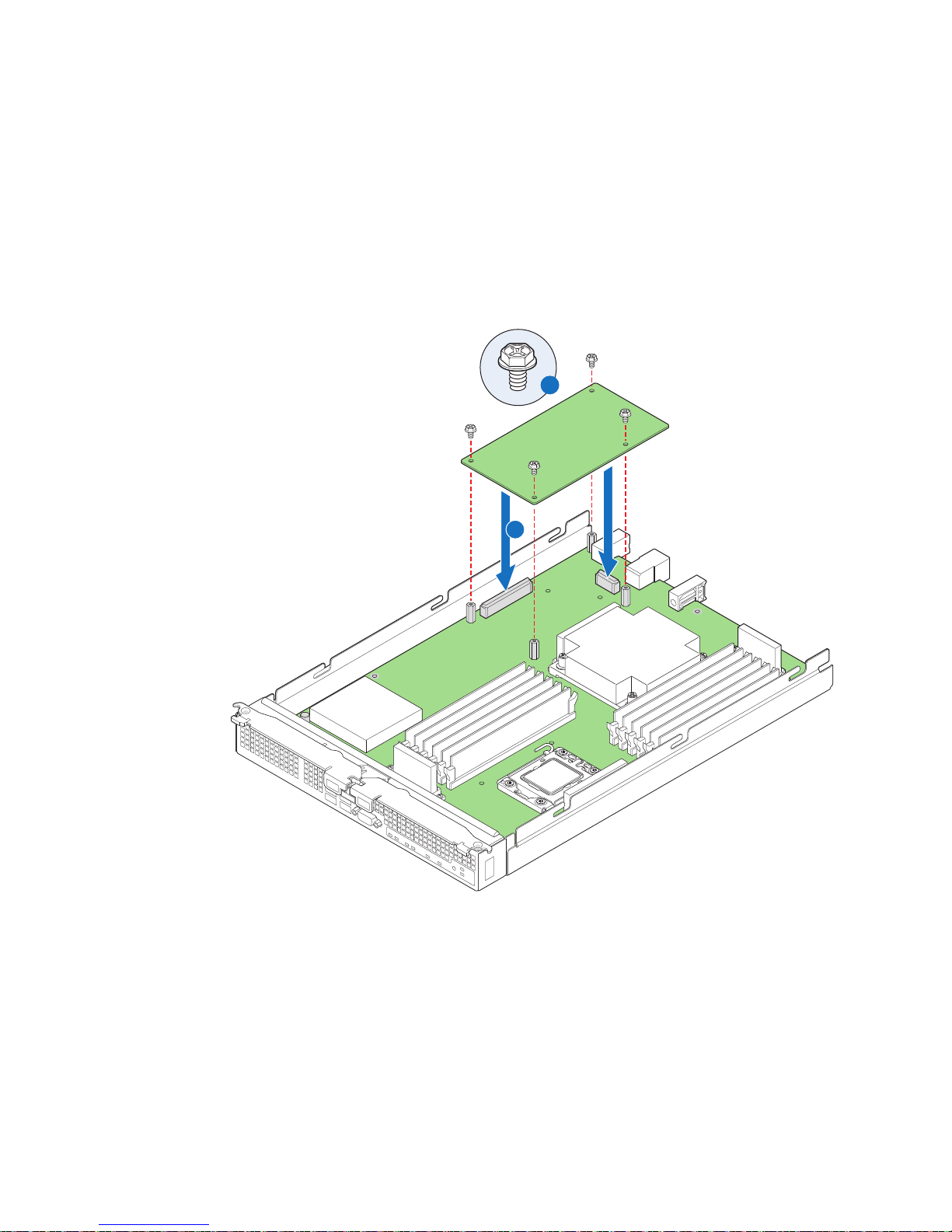
9. Position the mezzanine card above the mezzanine card connectors on the server board
1 I/O 2
ID
1 2
AF003083
Mezzanine Card
A
B
and align the four screw holes with the standoffs taking care to position each
connector housing on the mezzanine card with the connectors on the server board (see
letter “A” in Figure 38).
10. Carefully press the mezzanine card into place until it is fully seated in the connectors
and resting on the standoff supports.
11. Secure the mezzanine card to the standoffs with the four screws previously removed
(see letter “B” in Figure 38).
Figure 38. Installing and Securing the Mezzanine Card
12. Reinstall the top cover. For instructions, see “Installing the Top Cover” on page 16.
13. Reinstall the server compute module in the chassis. For instructions, see “Installing
a Compute Module into the Chassis” on page 14.
Intel® Compute Module MFS5520VI User Guide 45
Page 60

Removing a Mezzanine Card
1 I/O 2
ID
1 2
AF003091
To remove a mezzanine card, follow these steps:
1. Observe the safety and ESD information at the beginning of this manual and in the
appendices.
2. If the compute module is installed in a chassis, remove it. For instructions, see
“Removing a Compute Module from the Chassis” on page 13.
3. Remove the top cover. For instructions, see “Removing the Top Cover” on page 14.
4. Locate the mezzanine card.
5. Using a Phillips* screwdriver, remove the four screws securing the mezzanine card to
the standoffs (see Figure 39).
Figure 39. Removing Screws from Mezzanine Card
46 Intel® Compute Module MFS5520VI User Guide
Page 61

6. Holding the mezzanine card by its edges, gently lift it from the connectors and store it
1 I/O 2
ID
1 2
AF003092
Mezzanine Card
in an anti-static package (see Figure 40).
Intel® Compute Module MFS5520VI User Guide 47
Figure 40. Removing Mezzanine Card
Page 62

7. Using a 1/4-inch nut driver, remove the standoffs (see Figure 41).
1 I/O 2
1 2
ID
AF003093
Figure 41. Removing Standoffs
8. Using a Phillips* screwdriver, secure the four screws (that were previously
removed) into the holes vacated by the standoffs.
9. Reinstall the top cover. For instructions, see “Installing the Top Cover” on page 16.
10. Reinstall the server compute module in the chassis. For instructions, see “Installing
a Compute Module into the Chassis” on page 14.
48 Intel® Compute Module MFS5520VI User Guide
Page 63

Replacing the CMOS Battery
The lithium battery on the server board powers the RTC for up to 10 years in the absence
of power. When the battery starts to weaken, it loses voltage, and the server settings stored
in the CMOS RAM (for example, the date and time) may be wrong. Contact your
customer service representative or dealer for a list of approved replacement batteries.
Warni n g: Danger of explosion if battery is incorrectly replaced. Replace only with the same or
equivalent type recommended by the equipment manufacturer. Discard used batteries
according to manufacturer’s instructions.
Advarsel: Lithiumbatteri - Eksplosionsfare ved fejlagtig håndtering. Udskiftning må kun ske med
batteri af samme fabrikat og type. Levér det brugte batteri tilbage til leverandøren.
Advarsel: Lithiumbatteri - Eksplosjonsfare. Ved utskifting benyttes kun batteri som anbefalt av
apparatfabrikanten. Brukt batteri returneres apparatleverandøren.
Va rn i ng : Explosionsfara vid felaktigt batteribyte. Använd samma batterityp eller en ekvivalent typ
som rekommenderas av apparattillverkaren. Kassera använt batteri enligt fabrikantens
instruktion.
Varoitus: Paristo voi räjähtää, jos se on virheellisesti asennettu. Vaihda paristo ainoastaan
laitevalmistajan suosittelemaan tyyppiin. Hävitä käytetty paristo valmistajan ohjeiden
mukaisesti.
To replace the battery, follow these steps:
1. Observe the safety and ESD information at the beginning of this manual and in the
appendices.
2. If the compute module is installed in a chassis, remove it. For instructions, see
“Removing a Compute Module from the Chassis” on page 13.
3. Remove the top cover. For instructions, see “Removing the Top Cover” on page 14.
Intel® Compute Module MFS5520VI User Guide 49
Page 64
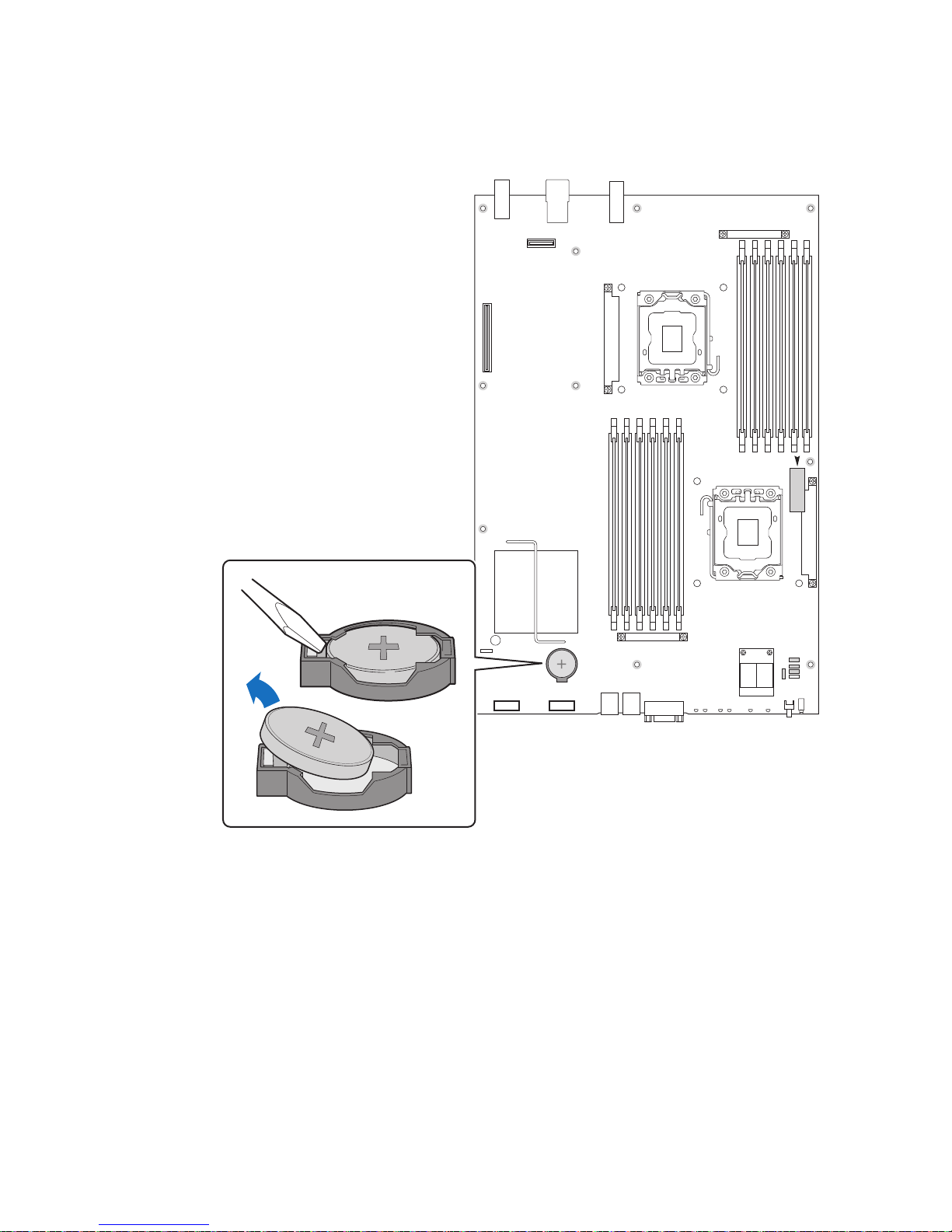
4. Locate the CMOS battery (see letter “A” in Figure 41).
5. Insert the tip of a small flat-head screwdriver, or equivalent, under the tab in the
plastic retainer. Gently push down on the screwdriver to lift the battery.
6. Remove the battery from its socket.
7. Dispose of the battery according to local ordinance.
8. Remove the new lithium battery from its package, and, being careful to observe the
correct polarity, insert it in the battery socket.
9. Reinstall the top cover. For instructions, see “Installing the Top Cover” on page 16.
10. Reinstall the server compute module in the chassis. For instructions, see “Installing
a Compute Module into the Chassis” on page 14
50 Intel® Compute Module MFS5520VI User Guide
AF003101
Figure 42. CMOS Battery Location
Page 65

11. Run the BIOS setup to restore the configuration settings to the RTC.
Intel® Compute Module MFS5520VI User Guide 51
Page 66

52 Intel® Compute Module MFS5520VI User Guide
Page 67

3 BIOS Setup Utility
This section describes the text-based BIOS Setup Utility. The BIOS Setup Utility is used
to view and modify configuration settings for the Intel
built-in devices, boot manager, and error manager. You can run the BIOS Setup Utility
with or without an operating system present.
Starting BIOS Setup Utility
To enter the BIOS Setup Utility, complete the following steps:
1. Before you begin either:
a. Start a Remote KVM and CD session with the target compute module through the
b. Or, connect a keyboard and monitor directly to the target compute module.
2. Power on or reboot the compute module using either the Intel
Control UI or by manually pressing the compute module power button.
3. Press the <F2> function key when the below message is displayed during boot time.
Press <F2> to enter SETUP
The message above is displayed after POST completes the memory test either below
the BIOS splash screen if quiet boot is enabled, or on the diagnostic screen if quiet
boot is disabled when you power on the compute module.
®
Intel
Modular Server Control UI. Refer to the Intel® Modular Server System
MFSYS25/MFSYS35 User Guide for information on using the Intel
Server Control UI.
®
Compute Module MFS5520VI’s
®
Modular
®
Modular Server
When the BIOS Setup Utility is entered, the Main screen is displayed by default. If
serious errors have occurred, the Error Manager screen is displayed instead of the
Main screen.
If You Cannot Access Setup
If you cannot access the BIOS Setup, you might need to clear the CMOS memory. For
instructions on clearing the CMOS, see Section , “Clearing the CMOS” on page -92.
General Layout and Navigation
The BIOS Setup page layout is sectioned into functional areas. Each occupies a specific
area of the screen and has a dedicated functionality. The following table lists and describes
each functional area.
Intel® Compute Module MFS5520VI User Guide 53
Page 68
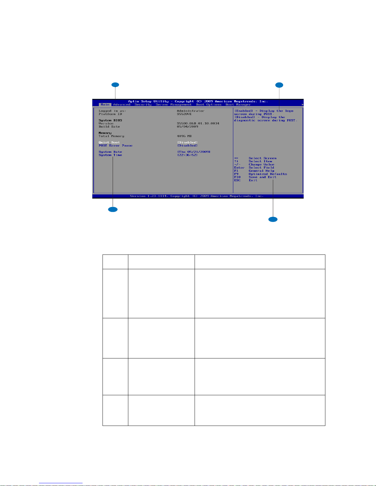
Functional Area Description
A
B
C
D
A Menu Selection Bar The Menu selection bar is located at the top of the
BIOS Setup Utility screen. It displays the major
menu selections available to the user. By using the
left and right arrow keys, the user can select the
listed menus. Some menus are hidden and
become available by scrolling to the left or right of
the current selection.
B Setup Item List The Setup Item List is a set of controllable and
informational items. Each item in the list occupies
the left column of the screen.
A Setup Item may also open a new window with
more options for that functionality on the board.
C Item-Specific Help Area The Item-specific Help area is located on the right
side of the screen and contains help text for the
highlighted Setup Item. Help information may
include the meaning and usage of the item,
allowable values, effects of the options, and so on.
D Keyboard Command Bar The Keyboard Command Bar is located at the
bottom right of the screen and continuously
displays help for keyboard special keys and
navigation keys.
Figure 43. Setup Layout
54 Intel® Compute Module MFS5520VI User Guide
Page 69

Table 4, “Keyboard Commands” , describes the keyboard commands you can use in the
BIOS Setup menus.
Table 4. Keyboard Commands
Press Description
<F1> Help - Pressing F1 on any menu invokes the general Help window.
← → The left and right arrow keys are used to move between the major menu
pages. The keys have no effect if a submenu or pick list is displayed.
↑ Select Item up - The up arrow is used to select the previous value in a menu
item's option list, or a value field pick list. Pressing the Enter key activates
the selected item.
↓ Select Item down - The down arrow is used to select the next value in a
menu item's option list, or a value field pick list. Pressing the Enter key
activates the selected item.
F5/- Change Value - The minus key or the F5 function key is used to change the
value of the current item to the previous value. This key scrolls through the
values in the associated pick list without displaying the full list.
F6/+ Change Value - The plus key or the F6 function key is used to change the
value of the current menu item to the next value. This ke y scrolls through the
values in the associated pick list without displaying the full list.
<Enter> Execute Command - The Enter key is used to activate submenus when the
selected feature is a submenu, or to display a pick list if a selected feature
has a value field, or to select a sub-field for multi-valued features like time
and date. If a pick list is displayed, the Enter key will undo the pick list, and
allow another selection in the parent menu.
<Esc> Exit - The ESC key provides a mechanism for backing out of any field. This
<F9> Setup Optimized Defaults - Pressing F9 causes the following to display:
key will undo the pressing of the Enter key. Wh en the ESC key is pressed
while editing any field or selecting features of a menu, the parent menu is reentered. When the ESC key is pressed in any submenu, the parent menu is
re-entered. When the ESC key is pressed in any major menu, the exit
confirmation window is displayed and the user is asked whether changes
can be discarded.
Intel® Compute Module MFS5520VI User Guide 55
If “Yes” is selected and the Enter key is pressed, all Setup fields are set to
their default values. If “No” is selected and the Enter key is pressed, or if the
ESC key is pressed, the user is returned to where they were before F9 was
pressed without affecting any existing field values.
Page 70
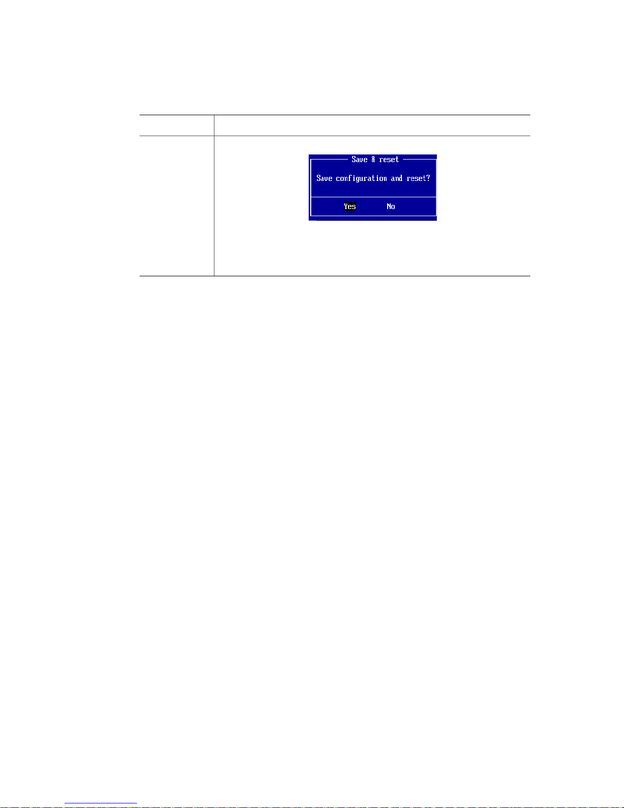
Table 4. Keyboard Commands
Press Description
<F10> Save and Exit - Pressing F10 causes the following message to display:
If “Yes” is selected and the Enter key is pressed, all changes are saved and
Setup is exited. If “No” is selected and the Enter key is pressed, or the ESC
key is pressed, the user is returned to where they were before F10 was
pressed without affecting any existing values.
56 Intel® Compute Module MFS5520VI User Guide
Page 71

Setup Menus
Each BIOS Setup menu page contains a number of features. Except for those features
provided only to display automatically configured information, each feature is associated
with a value field that contains user-selectable parameters. A user can change these
parameters if they have adequate security rights. If a value cannot be changed for any
reason, the feature’s value field is inaccessible.
The following sections describe the look and behavior for the BIOS Setup Utility. In these
sections, tables describe the contents of each screen. These tables follow the below
mentioned guidelines:
• The text and values in the Setup Item and Options columns are displayed on the BIOS
Setup screens.
• In the Options column, the default values are displayed in bold. These values do not
appear in bold on the BIOS Setup screen. The bold text in this document is to serve as
a reference point.
• Changes (except Date and Time) made in the Setup Utility are not applied until they
have been saved and the compute module has been rebooted.
Intel® Compute Module MFS5520VI User Guide 57
Page 72
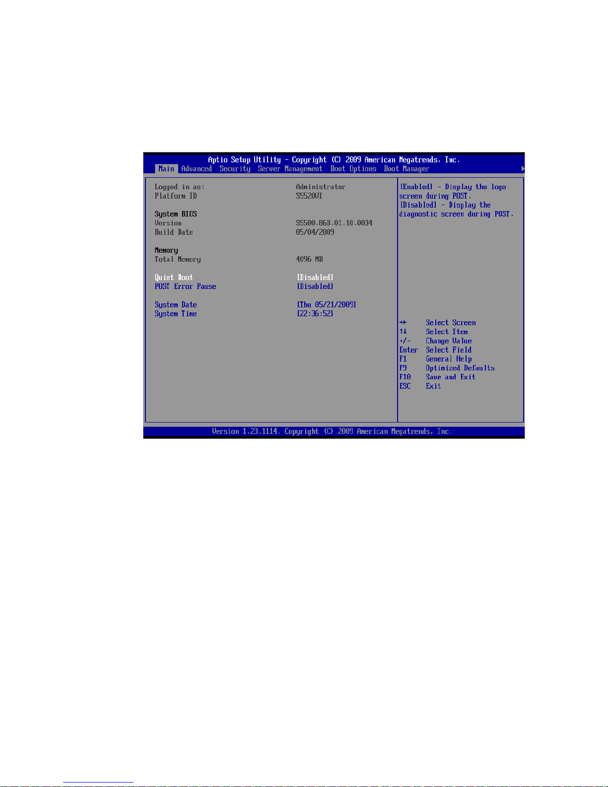
Main
The Main screen is the first screen that appears when the BIOS Setup is entered, unless an
error has occurred. If an error has occurred, the Error Manager screen is displayed instead.
Figure 44. Main Screen
58 Intel® Compute Module MFS5520VI User Guide
Page 73

The following table describes the features of the Main Setup screen.
Table 5. Main Screen Details
Setup Item Options Description
Logged in as Information only. Displays the current BIOS
Setup password level, Administrator or User. If no
passwords are set, Administrator is the default
mode.
Platform ID Information only. Displays the Platform ID
S5520VI
System BIOS
Version
System BIOS
Build Date
Total Memory Information only. Displays the total physical
Quiet Boot Enabled
Disabled
POST Error
Pause
System Date [Day of week
System Time [HH:MM:SS] System Time has configurable fields for Hours,
Enabled
Disabled
MM/DD/YYYY]
Information only. Displays the current BIOS
version.
Information only. Displays the current BIOS
build date.
memory installed in the compute module, in MB or
GB. The term physical memory indicates the total
memory discovered in the form of installed
DIMMs.
If Quiet Boot is enabled a logo screen is displayed
during POST. By default, Quiet Boot is enabled in
the BIOS setup. If the logo is displayed during
POST, press <Esc> to hide the logo and display
the diagnostic screen.
If a logo screen is not present in the flash ROM, or
if Quiet Boot is disabled, the summary and
diagnostic screen is displayed during POST.
If enabled, the POST Error Pause option takes the
compute module to the error manager to review
the critical POST errors when they occur. Minor
and fatal error displays are not affected by thi s
setting.
If disabled the compute module attempts to boot
and does not go to the Error Manager for critical
POST errors.
System Date has configurable fields for Month,
Day, and Year.
Use [Enter] or [Tab] key to select the next field.
Use [+] or [-] key to modify the selected field.
Minutes, and Seconds.
Hours are in 24-hour format.
Use the [Enter] or [T ab] k e y to select the next field.
Use the [+] or [-] key to modify the selected field.
Intel® Compute Module MFS5520VI User Guide 59
Page 74

Advanced
The Advanced screen provides a list of categories that can be configured by the user. The
categories act as links to the specific configuration screens for each option. Configuration
changes are note performed directly on the Advanced screen.
To access this screen from the Main screen, press the right arrow key until the Advanced
menu option is selected.
The following sections provide detailed information including images of the configuration
screens for each of the categories listed on the Advanced menu.
Processor Configuration
The Processor Configuration screen allows you to view detailed information for each
installed processor as well as configure several processor options.
60 Intel® Compute Module MFS5520VI User Guide
Figure 45. Advanced Screen
Page 75

To access this screen from the Main screen, press the right arrow key until the Advanced
menu option is selected then select Processor Configuration from the Advanced menu..
Figure 46. Advanced Processor Configuration Screen
Intel® Compute Module MFS5520VI User Guide 61
Page 76

The following table describes the features of the Advanced Processor Configuration
screen.
Table 6. Advanced Processor Configuration Details
Setup Item Options Description
Processor
Title
Configuration
Processor
Socket
Separates processor socket CPU1 and CPU2
information into two columns for the page layout.
Processor ID Information only. Processor CPUID.
Processor
Information only. Current frequency of the processor.
Frequency
Microcode
Information only. Revision of the loaded microcode.
Revision
L1 Cache RAM Information only. Size of the Processor L1 Cache.
L2 Cache RAM Information only. Size of the Processor L2 Cache
L3 Cache RAM Information only. Size of the Processor L3 Cache.
Processor 1
Information only. ID string from the Processor.
Version
Processor 2
Information only. ID string from the Processor.
Version
Current Intel
QPI Link Speed
®
Intel
QPI Link
Frequency
®
Intel
Turbo
Boost
Technology
Enabled
Disabled
Information only. Current speed used by the QPI
Link.
Information only. Current frequency used by the QPI
Link.
Intel® Turbo Boost Technology allows the processor
to automatically increase its frequency if it is running
below power, temperature, and current
®
specifications.
Enhanced Intel
SpeedStep
®
Te
chnology
Enabled
Disabled
Enhanced Intel SpeedStep
system to dynamically adjust processor voltage and
core frequency, which can result in decreased
®
Technology allows the
average power consumption and decreased average
heat production.
Contact your OS vendor regarding OS support of this
feature.
®
Intel
HyperThreading Tech
Enabled
Disabled
Intel® Hyper-Threading Technology allows multi
threaded software applications to execute threads in
parallel within each processor.
Contact your OS vendor regarding OS support of this
feature.
Core MultiProcessing
All
1
Enable 1, 2, or all cores of the installed processor
packages.
2
62 Intel® Compute Module MFS5520VI User Guide
Page 77

Table 6. Advanced Processor Configuration Details
Setup Item Options Description
Execute
Disable Bit
Intel®
Virtualization
Technology
Intel®
Virtualization
Technology for
Directed I/O
Hardware
Prefetcher
Adjacent Cache
Line Prefetch
Direct Cache
Access (DCA)
Enabled
Disabled
Enabled
Disabled
Enabled
Disabled
Enabled
Disabled
Enabled
Disabled
Enabled
Disabled
Execute Disable Bit can help prev ent certain classes
of malicious buffer overflow attacks.
Contact your OS vendor regarding OS support of this
feature.
Intel® Virtualization Technology allows a platform to
run multiple operating systems and applications in
independent partitions.
Enable/Disable Intel® Virtualization Technology for
Directed I/O.
Hardware Prefetcher is a speculative prefetch unit
within the processor(s).
NOTE: Modifying this setting may affect system
performance.
[Enabled] - Cache lines are fetched in pairs (even
line + odd line).
[Disabled] - Only the current cache line required is
fetched.
NOTE: Modifying this setting may affect system
performance.
Allows processors to increase the I/O performance
by placing data from I/O devices directly into the
processor cache.
Memory Configuration
The Advanced Memory Configuration screen provides information about the installed
memory modules. This screen also provides a link to configure memory RAS (Reliability,
Availability, and Serviceability) and view memory performance information and settings.
To access this screen from the Main screen press the right arrow key until the Advanced
menu option is selected then select Memory Configuration from the Advanced menu.
Intel® Compute Module MFS5520VI User Guide 63
Page 78

.
Figure 47. Advanced Memory Configuration Screen
64 Intel® Compute Module MFS5520VI User Guide
Page 79

The following table describes the features of the Advanced Memory Configuration screen.
Table 7. Advanced Memory Configuration Screen Details
Setup Item Options Description
Total Memory Information only. The amount of memory available in
the system in the form of installed DIMMs, in units of MB
or GB.
Effective
Memory
Current
Configuration
Information only. The amount of memory available to
the OS in MB or GB.
The Effective Memory is the difference between the
Total Physical Memory and the sum of all memory
reserved for internal usage, RAS redundancy and
SMRAM. This difference includes the sum of all DIMMs
that failed Memory BIST during POST or were disabled
by the BIOS during the memory discovery phase in
order to optimize memory configuration.
Information only. Displays one of the following:
• Independent Mode: System memory is configured
for optimal performance and efficiency and no RAS
is enabled.
• Mirror Mode: System memory is configured for
maximum reliability in the form of memory
mirroring.
Current
Memory Speed
Memory RAS
and
Performance
Configuration
DIMM_ XY Displays the state of each DIMM socket present on the
Information only. Displays the speed at which the
memory is running.
Select to configure memory RAS (Reliability , A v ailability,
and Serviceability) and view current memory
performance information and settings. This takes the
user to a different screen.
board. Each DIMM socket field reflects one of the
following possible states:
• Installed: There is a DIMM installed in this slot.
• Not Installed: There is no DIMM installed in this
slot.
• Disabled: The DIMM installed in this slot has been
disabled by the BIOS in order to optimize memory
configuration.
• Failed: The DIMM installed in this slot is faulty /
malfunctioning.
Note: X denotes the Channel Identifier and Y denotes
the DIMM Identifier within the Channel.
Memory RAS and Performance Configuration
The Memory RAS (Reliability, Availability, and Serviceability) and Performance
Configuration screen displays current memory performance information and settings.
Under capabilities, this screen displays whether memory mirroring is possible (Yes / No)
and allows the user to enable or disable NUMA optimization.
Intel® Compute Module MFS5520VI User Guide 65
Page 80

To access this screen from the Main screen press the right arrow key until the Advanced
menu is selected then select Memory Configuration. From the Memory Configuration
screen, select Memory RAS and Performance Configuration and press <Enter>.
Figure 48. Memory RAS and Performance Configuration Screen
Mass Storage Controller Configuration
The Mass Storage Controller Configuration screen allows you to enable or disable the
SAS controller. By default, the SAS controller is set to [Enabled]. This enables the
compute module to access the system storage. If the SAS controller is set to [Disabled],
the compute module will not be able to access storage.
66 Intel® Compute Module MFS5520VI User Guide
Page 81
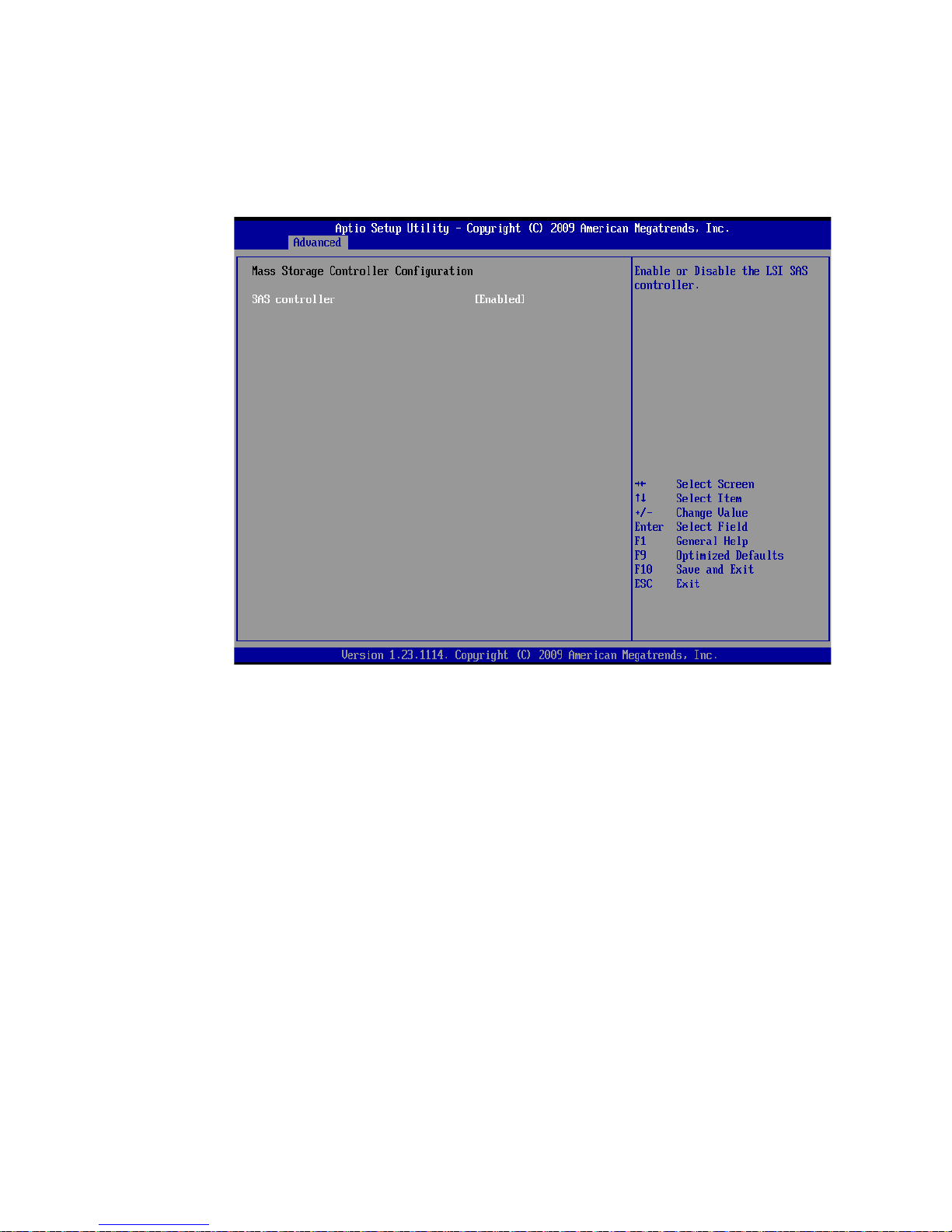
To access this screen from the Main menu press the right arrow key until the Advanced
menu is selected the press the down arrow key until Mass Storage Controller
Configuration is highlighted and press <Enter>.
Figure 49. Advanced Mass Storage Controller Configuration Screen
Serial Port Configuration
The Serial Port Configuration screen enables the user to configure the Network Serial
Console and the Debug Serial Port. To configure both the Network Serial Console and the
Debug Serial Port, the user can modify the following settings:
• Enable or Disable the serial port (Network Serial Console or Debug Serial Port)
• Select the base I/O address
• Select the interrupt request (IRQ) line
Intel® Compute Module MFS5520VI User Guide 67
Page 82

To access this screen from the Main screen press the right arrow key until the Advanced
menu is selected then press the down or up arrow key until Serial Port Configuration is
highlighted and press <Enter>..
USB Configuration
The USB Configuration screen allows you to configure the USB controller options.
Figure 50. Advanced Serial Port Configuration Screen
68 Intel® Compute Module MFS5520VI User Guide
Page 83
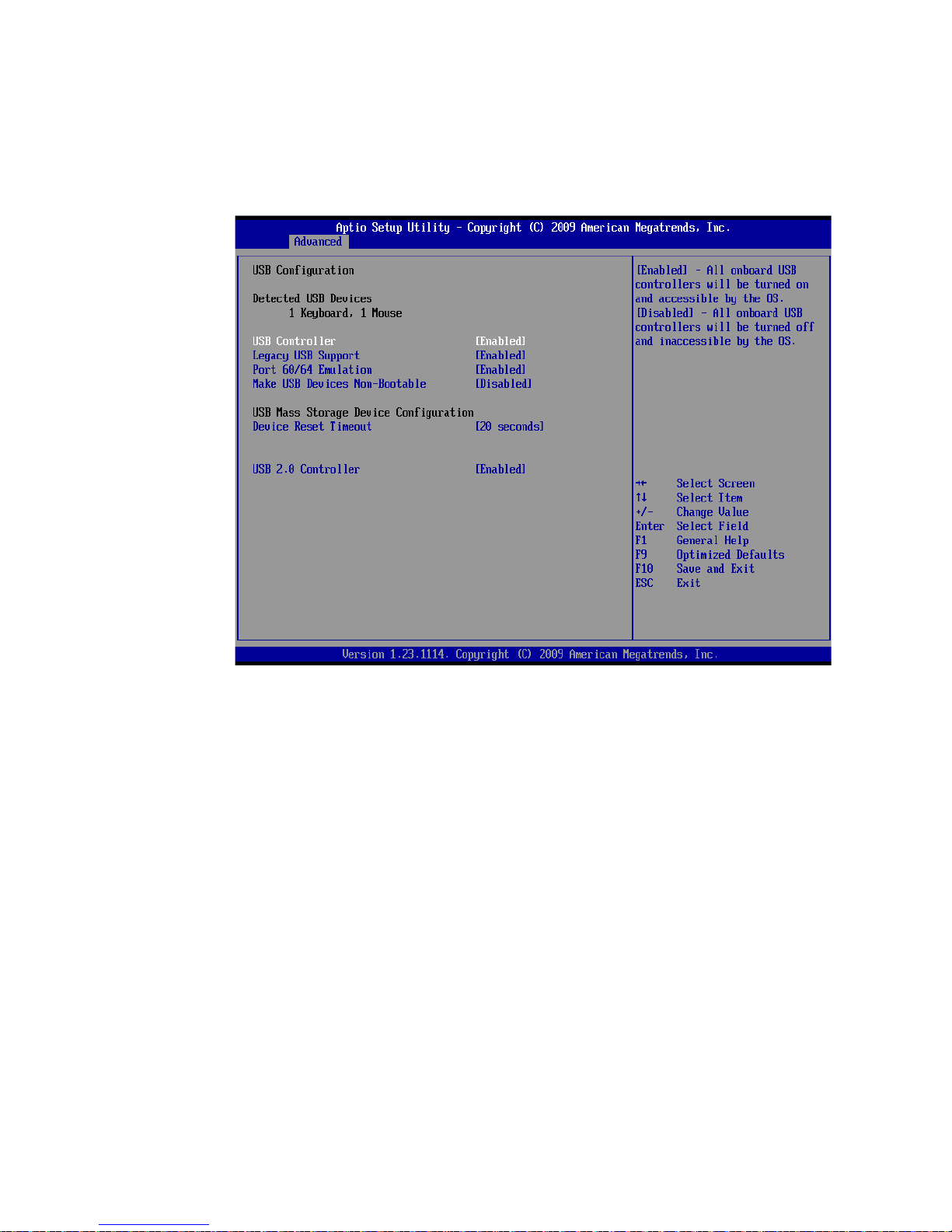
To access this screen from the Main screen press the right arrow key until the Advanced
menu is selected then press the down or up arrow key until USB Configuration is
highlighted and press <Enter>.
Figure 51. Advanced USB Configuration Screen
Intel® Compute Module MFS5520VI User Guide 69
Page 84

The following table describes the features of the Advanced USB Configuration screen
Table 8. USB Configuration Details
Setup Item Options Description
Detected USB
Devices
USB Controller Enabled
Disabled
Legacy USB
Support
Port 60/64
Emulation
Make USB
Devices NonBootable
Device Reset
time-out
USB 2.0
controller
Enabled
Disabled
Auto
Enabled
Disabled
Enabled
Disabled
10 sec
20 sec
30 sec
40 sec
Enabled
Disabled
Information only. Displays the number and
general description of USB devices detected for
the compute module.
By default, the USB Controller is enabled. When
enabled, all on-board USB controllers are turned
on and accessible by the OS. If disabled all onboard USB controllers are turned off and
inaccessible by the OS.
If disabled, the remaining configuration options on
this screen are grayed out.
USB device boot support and PS/2 emulation for
USB keyboard and USB mouse devices.
If auto is selected, Legacy USB support is
enabled if a USB device is attached
I/O port 60h/64h emulation support.
NOTE: This may be needed for legacy USB
keyboard support when using an OS that
is USB unaware.
Exclude USB in Boot Table.
If enabled, this will remove all USB Mass Storage
devices as Boot options.
If disabled, this allows all USB Mass Storage
devices as Boot options.
USB Mass Storage device start unit command
time-out.
Setting to a larger value provides more time for a
mass storage device to be ready, if needed.
When enabled on-board USB ports are enabled
to support USB 2.0 mode.
Contact your OS vendor regarding OS support of
this feature.
PCI Configuration
The PCI Configuration Screen allows you to configure the memory usage and on-board
NIC controllers.
70 Intel® Compute Module MFS5520VI User Guide
Page 85

To access this screen from the Main screen press the right arrow key until the Advanced
menu is selected then press the down or up arrow key to highlight PCI Configuration and
press <Enter>..
Figure 52. Advanced PCI Configuration Screen
Intel® Compute Module MFS5520VI User Guide 71
Page 86

The following table describes the features of the Advanced PCI Configuration screen.
Table 9. Advanced PCI Configuration Details
Setup Item Options Help Text
Maximize
Memory below
4GB
Memory
Mapped I/O
above 4GB
Onboard NIC1
ROM
Onboard NIC2
ROM
NIC 1 MAC
Address
NIC 2 MAC
Address
Enabled
Disabled
Enabled
Disabled
Enabled
Disabled
Enabled
Disabled
If enabled, BIOS maximizes usage of memory
below 4 GB for an OS without PAE by limiting
PCIe* Extended Configuration Space to 64
buses.
Enable or disable memory mapped I/O of 64-bit
PCI devices to 4 GB or greater address space.
Load the embedded option ROM for the
onboard network controllers.
Warning: If [Disabled] is selected, NIC1 cannot
be used to boot or wake the system.
Load the embedded option ROM for the
onboard network controllers.
Warning: If [Disabled] is selected, NIC2 cannot
be used to boot or wake the system
Information only. 12 hex digits of the MAC
address
Information only. 12 hex digits of the MAC
address.
System Acoustics and Performance Configuration
The System Acoustic and Performance Configuration screen allows the user to configure
the DIMM thermal management option for the Intel® Compute Module MFS5520VI.
Specifically the System Acoustics and Performance Configuration screen allows the user
to set the DIMM throttling mode to Auto (default), Static Closed Loop Thermal Throttling
(CLTT) or Static Open Loop Thermal Throttling (OLTT). By default this field is set to
Auto. When set to Auto the BIOS will configure the system for Static Closed Loop
Thermal Throttling (CLTT) as long as the installed DIMMs have Module Thermal
Sensors. With the Throttling mode set to CLTT the system is able to accurately control
memory temperatures, which is necessary to manage system performance within thermal
parameters.To set the throttling mode, select one of the following configuration options:
• [Auto] – Auto Throttling mode
• [CLTT] – Closed Loop Thermal Throttling Mode
• [OLTT] – Open Loop Thermal Throttling Mode
Notes: The OLTT option is shown for informational purposes only. If the user selects OLTT, the
BIOS overrides that selection if the system can support CLTT. OLTT is configured only
when unbuffered DIMMs
To access this screen from the Main screen press the right arrow key until the Advanced
menu is selected then press the down or up arrow key to highlight System Acoustics and
Performance Configuration and press <Enter>.
72 Intel® Compute Module MFS5520VI User Guide
(UDIMMs)UDIMMs without Thermal Sensors are installed.
Page 87

Security
Figure 53. Advanced System Acoustics and Performance Configuration
Screen
The Security screen allows you to enable and set the user and administrative passwords.
This screen also allows you to enable and activate the Trusted Platform Module (TPM)
security settings.
Intel® Compute Module MFS5520VI User Guide 73
Page 88

To access this screen from the Main screen, press the right arrow key until the Security
menu option is selected.
Figure 54. Security Screen
74 Intel® Compute Module MFS5520VI User Guide
Page 89

The following table describes the features of the Security screen.
Table 10. Security Screen Details
Setup Item Options Description
Administrator
Password
Status
User Password
Status
Set
Administrator
Password
Set User
Password
TPM State Enabled and
[123aBcD] An Administrator password is used to control
[123aBcD] The User password option is used to control entry
Activated
Enabled and
Deactivated
Disabled and
Activated
Disabled and
Deactivated
Information only. Indicates the status of the
administrator password (Installed or Not Installed).
Information only. Indicates the status of the user
password (Installed or Not Installed).
change in access in the BIOS Setup utility.
Administrator access provides full access to all the
setup options.
Only alphanumeric characters can be used. The
maximum length is 7 characters and it is case
sensitive. Clearing the Administrator password also
clears the user password.
NOTE: An Administrator password must be set in
order to enable the user account.
access to the BIOS Setup utility only. Set User
Password is available only if the administrator
password is installed. The user password has
limited access to the setup options. This option only
protects the setup.
Only alphanumeric characters can be used.
Maximum length is 7 characters and it is case
sensitive.
NOTE: Removing the administrator password also
automatically removes the user password.
Information only.
This Shows the current TPM device state.
A disabled TPM device does not execute
commands that use the TPM functions and TPM
security operations are not available.
An enabled and deactivated TPM is in the same
state as a disabled TPM, except that setting of the
TPM ownership is allowed if it is not present
already.
An enabled and activated TPM executes all
commands that use the TPM functions and TPM
security operations are also available.
Intel® Compute Module MFS5520VI User Guide 75
Page 90
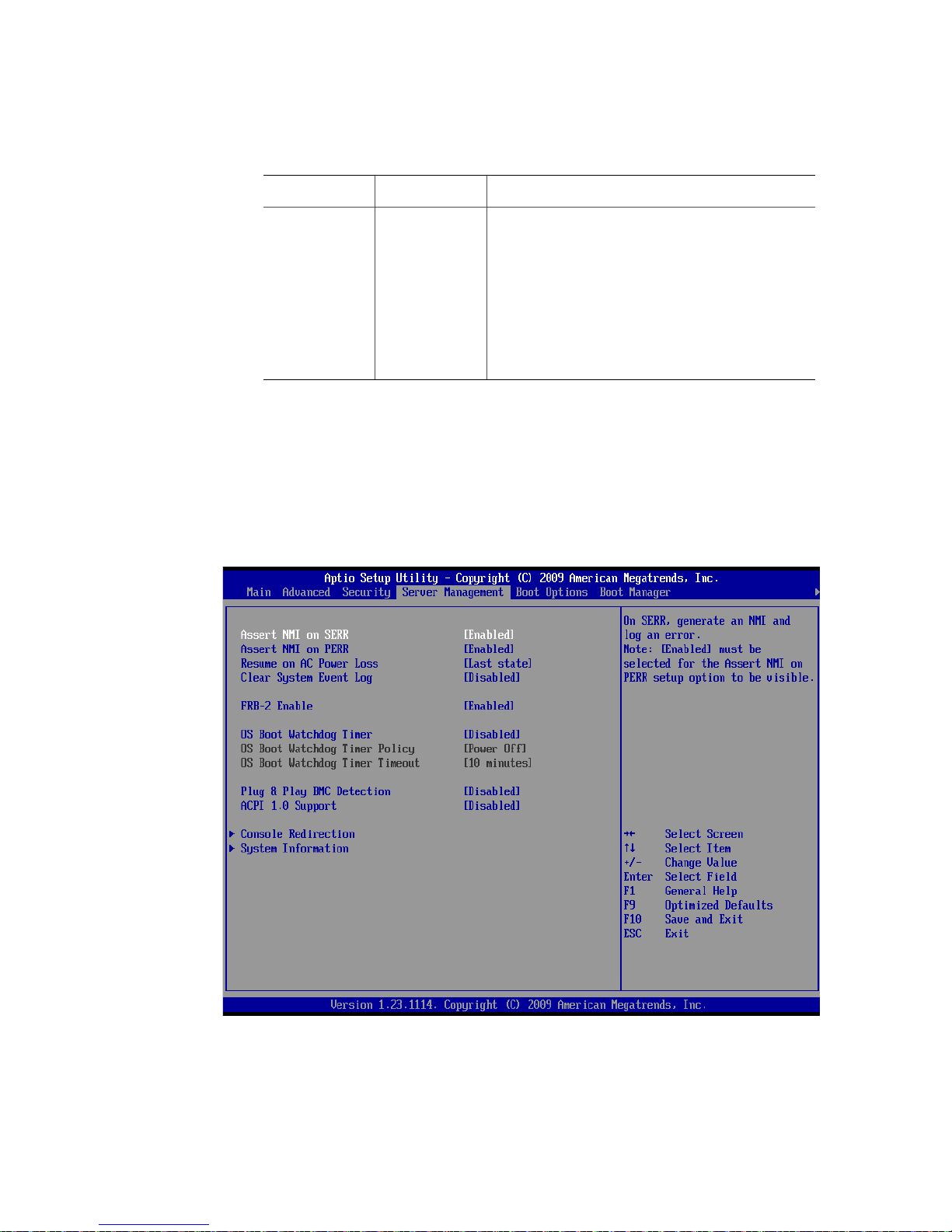
Table 10. Security Screen Details
Setup Item Options Description
TPM
Administrative
Control
Server Management
The Server Management screen allows you to configure several server management
features. This screen also provides an access point to the screens for configuring console
redirection and displaying system information.
To access this screen from the Main screen, press the right arrow key until the Server
Management menu option is selected.
No Operation
Turn On
Turn Off
Clear
Ownership
TPM Administrative control can be set to:
• [No Operation] - No changes to current state.
• [Turn On] - Enables and activates TPM.
• [Turn Off] - Disables and deactivates TPM.
• [Clear Ownership] - Removes the TPM
ownership authentication and returns the TPM
to the factory default state.
NOTE: The BIOS setting returns to [No Operation]
on every boot cycle by default.
76 Intel® Compute Module MFS5520VI User Guide
Figure 55. Server Management Screen
Page 91

The following table describes the features of the Server Management screen.
Table 11. Server Management Screen Details
Setup Item Options Description
Assert NMI on
SERR
Assert NMI on
PERR
Resume on AC
Power Loss
Clear System
Event Log
FRB-2 Enable Enabled
O/S Boot
Watchdog
Timer
O/S Boot
Watchdog
Timer Policy
O/S Boot
Watchdog
Timer Timeout
Plug & Play
BMC Detection
Enabled
Disabled
Enabled
Disabled
Stay Off
Last state
Reset
Enabled
Disabled
Disabled
Enabled
Disabled
Power Off
Reset
5 minutes
10 minutes
15 minutes
20 minutes
Enabled
Disabled
On SERR, generate an NMI and log an error.
On PERR, generate an NMI and log an error.
NOTE: This option is only active if the Assert NMI on
SERR option is [Enabled] selected.
Set the compute module action to take on AC power
loss recovery.
[Stay Off] - compute module stays off.
[Last State] - compute module returns to the same
state before the AC power loss.
[Reset] - compute module powers on.
If enabled, this option clears the System Event Log.
All current entries are lost after saving changes and
rebooting the compute module.
NOTE: This option is reset to [Disabled] after a
Fault Resilient Boot (FRB).
If enabled, the BIOS programs the BMC watchdog
timer for approximately 6 minutes. If the BIOS does
not complete POST before the timer expires, the
BMC resets the compute module.
BIOS programs the watchdog timer with the timeout
value selected. If the OS does not complete booting
before the timer expires , the BMC resets the compute
module and an error is logged.
Requires OS support or Intel
Software.
If the OS watchdog timer is enabled, this is the
compute module action taken if the watchdog timer
expires.
[Reset] - Compute module performs a reset.
[Power Off] - Compute module powers off.
NOTE: This option is grayed out when O/S Boot
If the OS watchdog timer is enabled, this is the
timeout value BIOS will use to configure the
watchdog timer.
NOTE: This option is grayed out when O/S Boot
If enabled, BMC will be detectable by OSs which
support plug and play loading of an IPMI driver. Do
not enable if your OS does not support this driver.
reboot.
®
Management
Watchdog Timer is disabled.
Watchdog Timer is disabled.
Intel® Compute Module MFS5520VI User Guide 77
Page 92

Table 11. Server Management Screen Details
Setup Item Options Description
Console Redirection
Console redirection enables a serial port to be used for server management tasks. The
Console Redirection screen enables the user to either disable console redirection or enable
console redirection through the Network Serial Console. If Console Redirection is set to
Network Serial Console, the console redirection configuration options Flow Control,
Baud Rate, Terminal Type, and Legacy OS Redirection are displayed on the Console
Redirection Setup screen. Enabling console redirection sets the BIOS option Quiet Boot to
[Disable]. The BIOS logo screen is not displayed during POST while console redirection
is enabled.
ACPI 1.0
Support
Console
Redirection
System
Information
Enabled
Disabled
<Enter> Select Console Redirection to view/configure console
<Enter> View system information.
[Enabled] - Publish ACPI 1.0 version of FADT in Root
System Description Table.
This may be required for compatibility with OS
versions that only support ACPI 1.0.
NOTE: Set to [Enabled] for Microsoft Windows
Server 2000* support.
redirection information and settings.
This option takes the user to the Console Redirection
screen.
This option takes the user to the System Information
screen.
78 Intel® Compute Module MFS5520VI User Guide
Page 93

To access this screen from the Main screen, press the right arrow key until the Server
Management menu option is selected then select Console Redirection.
Figure 56. Server Management - Console Redirection Enabled Screen
Intel® Compute Module MFS5520VI User Guide 79
Page 94

The following table describes the features of the Console Redirection screen.
Table 12. Server Management Console Redirection Details
Setup Item Options Description
Console
Redirection
Flow Control None
Baud Rate 9600
Terminal Type PC-ANSI
Legacy OS
Redirection
Disabled
Network Serial
Console
RTS/CTS
19.2K
38.4K
57.6K
115.2K
VT100
VT100+
VT-UTF8
Disabled
Enabled
Console redirection allows a serial port to be used
for server management tasks.
If disabled the console redirection configuration
options will not be displayed.
If set to [Network Serial Console], console
redirection is enabled and the configuration
options will be displayed.
NOTE: Enabling this option will set Quiet Boot to
disable. The BIOS logo screen will not be
displayed during POST while console
redirection is enabled.
Flow control is the handshake protocol.
This setting must match the remote terminal
application.
[None] - Configure for no flow control.
[RTS/CTS] - Configure for hardware flow control.
Serial port transmission speed. This setting must
match the remote terminal application.
Character formatting used for console redirection.
This setting must match the remote terminal
application.
This option enables legacy OS redirection (that is,
DOS) on serial port. If it is enabled, the associated
serial port is hidden from the legacy OS.
System Information
The System Information screen provides the following information for the compute
module:
• Board part number
• Board serial number
• Asset tag
• BMC firmware revision
• SDR revision
• UUID
80 Intel® Compute Module MFS5520VI User Guide
Page 95

To access this screen from the Main screen, press the right arrow key until the Server
Management menu option is selected then press the down or up arrow key to highlight
System Information and press <Enter>.
Figure 57. Server Management - System Information Screen
Boot Options
The Boot Options screen displays any bootable media encountered during POST, and
allows you to configure the desired order in which boot devices are to be tried. The first
boot device in the specified boot order will be used to boot the compute module.
Intel® Compute Module MFS5520VI User Guide 81
Page 96

To access this screen from the Main screen, press the right arrow key until the Boot
Options menu option is selected.
Figure 58. Boot Options Screen
82 Intel® Compute Module MFS5520VI User Guide
Page 97

The following table describes the features of the Boot Options screen.
Table 13. Boot Options Details
Setup Item Options Help Text
Boot Timeout 0 - 65535 The number of seconds BIOS will pause at the
end of POST to allow the user to press the [F2]
key for entering the BIOS Setup utility.
Valid values are 0-65535. Zero is the default. A
value of 65535 causes the compute module to
go to the Boot Manager menu and wait for user
input for ev ery boot. These settings are in
seconds.
After entering the desired timeout, press the
<Enter> key to register that timeout value.
Boot Option #x Available boot
devices
Network Device
Order
Hard Disk
Order
Delete Boot
Option
EFI Optimized
Boot
Boot Option
Retry
USB Boot
Priority
<Enter> Set network device bo o t ord e r.
<Enter> Set the hard disk drive boot order. This option
<Enter> Remove an EFI boot option from the boot order.
Enabled
Disabled
Enabled
Disabled
Enabled
Disabled
Set system boot order by selecting the boot
option for this position.
This option takes the user to a separate screen.
The Network Device Order screen which allows
the user to select the boot order for the available
network bootable devices.
takes the user to a separate screen. The Hard
Disk Order screen which allows the user to
select the boot order for the available bootable
devices.
This option takes the user to a new screen titled
Delete Boot Option. This new screen allows the
user to select an EFI boot option from the boot
order for deletion.
If the EFI shell is deleted, it is restored on the
next compute module rebo o t. It cann o t be
permanently deleted.
If enabled, the BIOS will only load modules
required for booting EFI-aware Operating
Systems.
This will continually retry non-EFI-based boot
options without waiting for user input.
If enabled, newly discovered USB devices will be
put to the top of their boot device category.
If disabled, newly discovered USB devices will
be put at the bottom of their boot device
catergory.
Intel® Compute Module MFS5520VI User Guide 83
Page 98
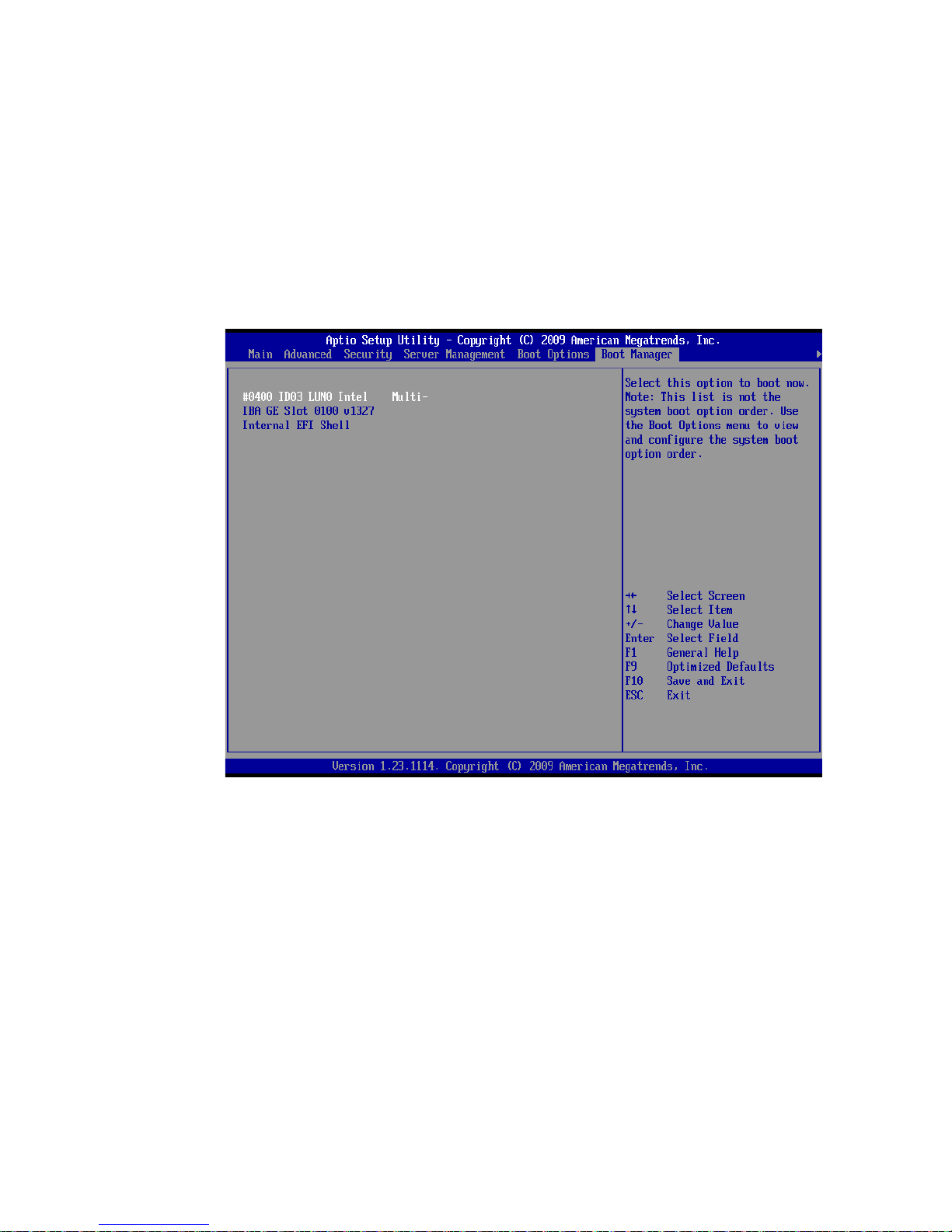
Boot Manager
The Boot Manager screen allows you to view a list of devices available for booting, and to
select a boot device for immediately booting the compute module. This list is not
displayed in the order configured on the Boot Options menu. Use the Boot Options menu
to view and configure the compute module boot option order.
To access this screen from the Main screen, press the right arrow key until the Boot
Manager menu option is selected.
84 Intel® Compute Module MFS5520VI User Guide
Figure 59. Boot Manager Screen
Page 99

Error Manager
The Error Manager screen displays any errors encountered during POST.
To access this screen from the Main screen, press the right arrow key until the Error
Manager menu option is selected.
Figure 60. Error Manager Screen
Intel® Compute Module MFS5520VI User Guide 85
Page 100
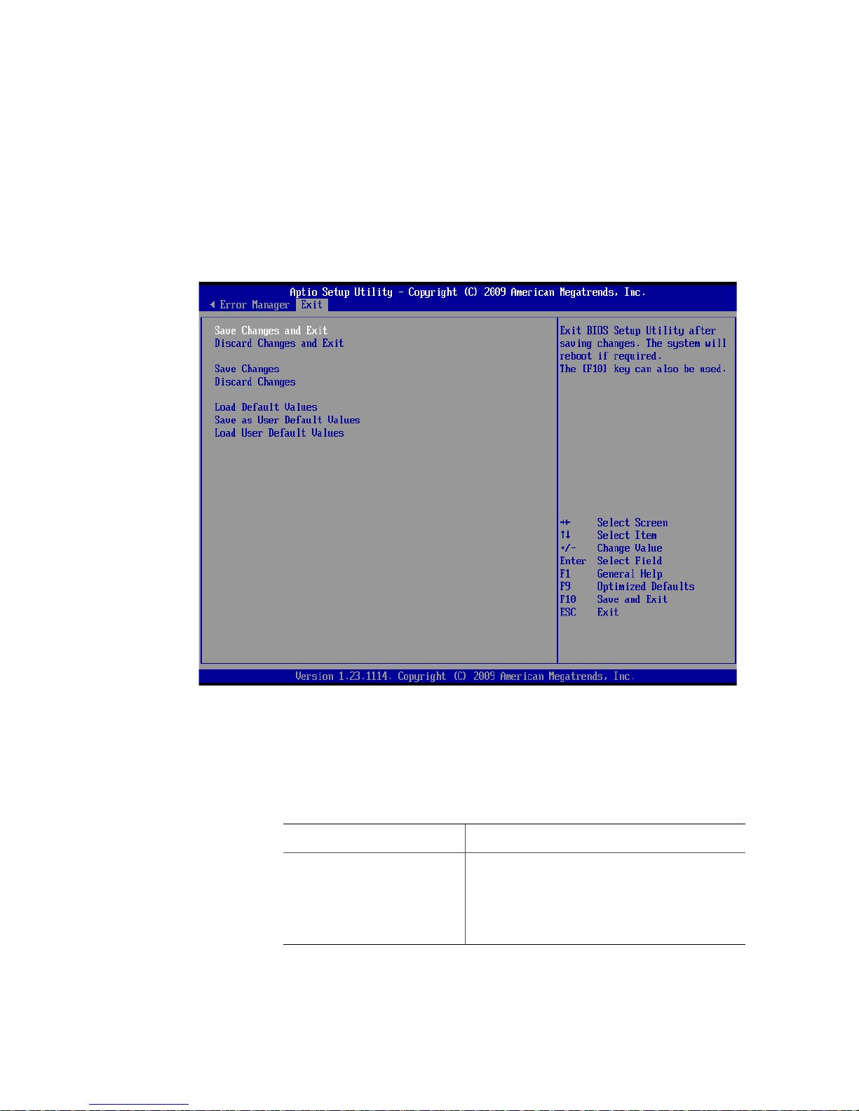
Exit
The Exit screen provides the user with the ability to save or discard changes before exiting
the utility, to save changes as a user defined default configuration, and to load either the
factory or user defined default settings.
To access this screen from the Main screen, press the right arrow until the Exit option is
selected.
The following table describes the options available on the Exit screen.
Table 14. Exit Screen Details
86 Intel® Compute Module MFS5520VI User Guide
Figure 61. Exit Screen
Setup Item Description
Save Changes and Exit If any of the setup fields were modified a
confirmation prompt will be displayed before the
changes are saved. After saving changes and
exiting the BIOS Setup Utility the compute
module will be rebooted if required. The <F10>
key can also be used.
 Loading...