

Page 1

Intel® Compute Module MFS5000SI User
Guide
A Guide for Technically Qualified Assemblers of Intel® Identified Subassemblies/
Products
Intel Order Number D90834-005
Page 2

Disclaimer
Information in this document is provided in connection with Intel® products. No license, express or implied, by
estoppel or otherwise, to any intellectual property rights is granted by this document. Except as provided in Intel's
Terms and Conditions of Sale for such products, Intel assumes no liability whatsoever, and Intel disclaims any
express or implied warranty, relating to sale and/or use of Intel® products including liability or warranties relating to
fitness for a particular purpose, merchantability, or infringement of any patent, copyright or other intellectual property
right. Intel products are not designed, intended or authorized for use in any medical, life saving, or life sustaining
applications or for any other application in which the failure of the Intel product could create a situation where
personal injury or death may occur. Intel may make changes to specifications and product descriptions at any time,
without notice.
Intel® server boards contain a number of high-density VLSI and power delivery components that need adequate
airflow for cooling. Intel's own chassis are designed and tested to meet the intended thermal requirements of these
components when the fully integrated system is used together. It is the responsibility of the system integrator that
chooses not to use Intel developed server building blocks to consult vendor datasheets and operating parameters to
determine the amount of airflow required for their specific application and environmental conditions. Intel
Corporation can not be held responsible if components fail or the server board does not operate correctly when used
outside any of their published operating or non-operating limits.
Intel, Intel Pentium, and Intel Xeon are trademarks or registered trademarks of Intel Corporation or its subsidiaries in
the United States and other countries.
* Other names and brands may be claimed as the property of others.
Copyright © 2007-2008, Intel Corporation. All Rights Reserved
Page 3
Safety Information
Important Safety Instructions
Read all caution and safety statements in this document before performing any of the
instructions. See also Intel® Server Boards and Server Chassis Safety Information at
http://support.intel.com/support/motherboards/server/sb/cs-010770.htm.
Wichtige Sicherheitshinweise
Lesen Sie zunächst sämtliche Warnund Sicherheitshinweise in diesem Dokument, bevor
Sie eine der Anweisungen ausführen. Beachten Sie hierzu auch die Intel® Server Boards
and Server Chassis Safety Information unter http://support.intel.com/support/
motherboards/server/sb/cs-010770.htm.
Consignes de sécurité
Lisez attention toutes les consignes de sécurité et les mises en garde indiquées dans ce
document avant de suivre toute instruction. Consultez Intel® Server Boards and Server
Chassis Safety Information sur le site http://support.intel.com/support/motherboards/
server/sb/cs-010770.htm.
Instrucciones de seguridad importantes
Lea todas las declaraciones de seguridad y precaución de este documento antes de realizar
cualquiera de las instrucciones. Vea Intel® Server Boards and Server Chassis Safety
Information en http://support.intel.com/support/motherboards/server/sb/cs-010770.htm.
重要安全指导
Intel® Compute Module MFS5000SI User Guide iii
Page 4

Warnings
These warnings and cautions apply whenever you remove the compute module enclosure
cover to access components inside the system. Only a technically qualified person should
maintain or configure the system.
Heed safety instructions: Before working with your server product, whether you are
using this guide or any other resource as a reference, pay close attention to the safety
instructions. You must adhere to the assembly instructions in this guide to ensure and
maintain compliance with existing product certifications and approvals. Use only the
described, regulated components specified in this guide. Use of other products /
components will void the UL listing and other regulatory approvals of the product and
will most likely result in noncompliance with product regulations in the region(s) in which
the product is sold.
System power on/off: The power button DOES NOT turn off the system AC power. To
remove power from the system, you must unplug the AC power cord from the wall outlet
or the chassis. Make sure the AC power cord is unplugged before you open the chassis,
add, or remove any components.
Hazardous conditions, devices and cables: Hazardous electrical conditions may be
present on power, telephone, and communication cables. Turn off the system and
disconnect the power cord, telecommunications systems, networks, and modems attached
to the system before opening it. Otherwise, personal injury or equipment damage can
result.
Electrostatic discharge (ESD) and ESD protection: ESD can damage disk drives,
boards, and other parts. We recommend that you perform all procedures in this document
only at an ESD workstation. If one is not available, provide some ESD protection by
wearing an anti-static wrist strap attached to chassis ground (any unpainted metal surface)
on your system when handling parts.
ESD and handling electronic devices: Always handle electronic devices carefully. They
can be extremely sensitive to ESD. Do not touch the connector contacts.
Installing or removing jumpers: A jumper is a small plastic encased conductor that slips
over two jumper pins. Some jumpers have a small tab on top that you can grip with your
fingertips or with a pair of fine needle nosed pliers. If your jumpers do not have such a
tab, take care when using needle nosed pliers to remove or install a jumper; grip the
narrow sides of the jumper with the pliers, never the wide sides. Gripping the wide sides
can damage the contacts inside the jumper, causing intermittent problems with the
function controlled by that jumper. Take care to grip with, but not squeeze, the pliers or
other tool you use to remove a jumper, or you may bend or break the pins on the board.
Reinstalling enclosure cover: To protect internal components and for proper cooling and
airflow, the compute module should not be inserted into the chassis with the cover
removed; operating it without the enclosure cover in place can damage system parts.
iv Intel® Compute Module MFS5000SI User Guide
Page 5

Contents
Safety Information ..................................................................................................... iii
Important Safety Instructions ................................................................................................ iii
Wichtige Sicherheitshinweise ............................................................................................... iii
Consignes de sécurité .......................................................................................................... iii
Instrucciones de seguridad importantes ............................................................................... iii
Warnings............................................................................................................................... iv
Compute Module Features ........................................................................................ 1
Connector and Component Locations ................................................................................... 3
Configuration Jumpers........................................................................................................... 4
Front Panel Connectors and Indicators .................................................................................5
Hardware Requirements ........................................................................................................5
Processor .................................................................................................................................... 5
Memory ....................................................................................................................................... 5
Power Supply .............................................................................................................................. 6
Hardware Installations and Upgrades ......................................................................7
Before You Begin ...................................................................................................................7
Tools and Supplies Needed ........................................................................................................ 7
Installation Guidelines ................................................................................................................. 7
Removing and Installing an Intel® Compute Module MFS5000SI .........................................7
Removing a Compute Module from the Server System ............................................................. 7
Installing a Compute Module into the Server System ................................................................. 8
Opening and Closing the Top Cover .....................................................................................8
Opening and Removing the Top Cover ...................................................................................... 8
Replacing and Closing the Top Cover ...................................................................................... 10
Installing or Replacing a Processor ..................................................................................... 11
Installing a Processor ............................................................................................................... 11
Replacing a Processor .............................................................................................................. 18
Installing and Removing Memory Modules.......................................................................... 24
Supported Memory ................................................................................................................... 24
Memory Sparing and Mirroring ................................................................................................ 24
Installing DIMMs ....................................................................................................................... 25
Removing DIMMs ..................................................................................................................... 29
Installing and Removing Mezzanine Card ........................................................................... 32
Installing the Mezzanine Card ..................................................................................................32
Removing a Mezzanine Card ................................................................................................... 35
Replacing the CMOS Battery............................................................................................... 39
Troubleshooting .......................................................................................................41
First Steps Checklist ............................................................................................................41
Intel® Compute Module MFS5000SI User Guide v
Page 6

Hardware Diagnostic Testing .............................................................................................. 42
Specific Problems and Corrective Actions .......................................................................... 42
Power LED Does Not Light .......................................................................................................43
No Video Display ...................................................................................................................... 43
Characters are Distorted or Incorrect ....................................................................................... 43
No Available Storage ................................................................................................................ 44
Cannot Connect to a Compute Module .................................................................................... 44
Problems with Newly Installed Application Software ................................................................ 45
Problems with Application Software that Previously Functioned Properly ............................... 45
Devices are Not Recognized within the Operating System ...................................................... 45
Diagnostic LED Information ...................................................................................................... 46
BIOS POST Beep Codes ......................................................................................................... 46
A Getting Help ..........................................................................................................49
World Wide Web .................................................................................................................49
Telephone ........................................................................................................................... 49
U.S. and Canada ...................................................................................................................... 49
Europe ...................................................................................................................................... 49
In Asia-Pacific region ................................................................................................................ 50
Japan ...................................................................................................................................... 50
Latin America ............................................................................................................................ 50
B Warranty ................................................................................................................53
Limited Warranty for Intel® Chassis Subassembly Products .............................................. 53
Extent of Limited Warranty .................................................................................................. 53
Warranty Limitations and Exclusions .................................................................................. 54
Limitations of Liability ............................................................................................................... 54
How to Obtain Warranty Service .............................................................................................. 54
Telephone Support ................................................................................................................... 55
Returning a Defective Product ..................................................................................................55
C Product Regulatory Requirements .....................................................................57
Product Safety Requirements ............................................................................................. 57
Electro Magnetic Compatibility (EMC) / Harmonic Requirements ....................................... 57
Product Ecology Requirements ........................................................................................... 57
Component Regulatory Requirements Needed to Support System Level Certifications .... 58
Product Regulatory Compliance and Safety Markings ........................................................ 59
D Safety Information ................................................................................................61
English ................................................................................................................................. 61
Server Safety Information ......................................................................................................... 61
Safety Warnings and Cautions ................................................................................................. 61
Intended Application Uses ........................................................................................................ 62
Site Selection ............................................................................................................................ 62
Equipment Handling Practices ................................................................................................. 62
Power and Electrical Warnings ................................................................................................. 62
System Access Warnings .........................................................................................................63
Rack Mount Warnings .............................................................................................................. 64
vi Intel® Compute Module MFS5000SI User Guide
Page 7

Electrostatic Discharge (ESD) ..................................................................................................64
Other Hazards .......................................................................................................................... 65
Deutsch................................................................................................................................ 66
Sicherheitshinweise für den Server .......................................................................................... 66
Sicherheitshinweise und Vorsichtsmaßnahmen ....................................................................... 66
Zielbenutzer der Anwendung .................................................................................................... 67
Standortauswahl ....................................................................................................................... 67
Handhabung von Geräten ........................................................................................................ 67
Warnhinweise für den Systemzugang ...................................................................................... 69
Elektrostatische Entladungen (ESD) ........................................................................................ 70
Andere Gefahren ...................................................................................................................... 71
Français ...............................................................................................................................72
Consignes de sécurité sur le serveur ....................................................................................... 72
Sécurité: avertissements et mises en garde ............................................................................. 72
Domaines d’utilisation prévus ................................................................................................... 73
Sélection d’un emplacement .....................................................................................................73
Pratiques de manipulation de l’équipement .............................................................................. 73
Décharges électrostatiques (ESD) ........................................................................................... 76
Autres risques ........................................................................................................................... 77
Español................................................................................................................................ 78
Información de seguridad del servidor ...................................................................................... 78
Advertencias y precauciones sobre seguridad ......................................................................... 78
Aplicaciones y usos previstos ................................................................................................... 79
Selección de la ubicación ......................................................................................................... 79
Manipulación del equipo ........................................................................................................... 79
Advertencias el acceso al sistema ............................................................................................ 81
Descarga electrostática (ESD) ................................................................................................. 82
E Installation/Assembly Safety Instructions .........................................................89
English .................................................................................................................................89
Deutsch ................................................................................................................................91
Français ...............................................................................................................................94
Español ................................................................................................................................96
Italiano .................................................................................................................................98
Intel® Compute Module MFS5000SI User Guide vii
Page 8

viii Intel® Compute Module MFS5000SI User Guide
Page 9

List of Tables
Table 1. Compute Module Features........................................................................................... 2
Table 2. Diagnostic LED Information........................................................................................46
Table 3. POST Error Beep Codes............................................................................................ 47
Intel® Compute Module MFS5000SI User Guide ix
Page 10

x Intel® Compute Module MFS5000SI User Guide
Page 11

List of Figures
Figure 1. Intel® Compute Module MFS5000SI ......................................................................... 1
Figure 2. Server Board............................................................................................................... 1
Figure 3. Component and Connector Locations.........................................................................3
Figure 4. Configuration Jumper Locations ................................................................................. 4
Figure 5. Front Panel Connectors and Indicators.......................................................................5
Figure 6. Removing Top Cover .................................................................................................. 9
Figure 7. Installing Top Cover ..................................................................................................10
Figure 8. Removing Processor Air Duct................................................................................... 11
Figure 9. Lifting Processor Socket Handle............................................................................... 12
Figure 10. Opening Load Plate ................................................................................................ 12
Figure 11. Removing Protective Shipping Cover ..................................................................... 13
Figure 12. Orienting and Installing Processor .......................................................................... 13
Figure 13. Removing Socket Protective Cover ........................................................................ 14
Figure 14. Lowering Load Plate and Socket Lever ..................................................................14
Figure 15. Installing Heatsink................................................................................................... 15
Figure 16. Removing Second Processor Air Baffle.................................................................. 16
Figure 17. Reinstalling Processor Air Duct...............................................................................17
Figure 18. Removing Processor Air Duct................................................................................. 18
Figure 19. Removing the Heatsink........................................................................................... 19
Figure 20. Lifting Processor Socket Handle............................................................................. 19
Figure 21. Opening Load Plate ................................................................................................ 20
Figure 22. Removing Processor............................................................................................... 20
Figure 23. Removing Protective Shipping Cover ..................................................................... 21
Figure 24. Orienting and Installing Processor .......................................................................... 21
Figure 25. Lowering Load Plate and Socket Lever ..................................................................21
Figure 26. Re-installing Heatsink ............................................................................................. 22
Figure 27. Reinstalling Processor Air Duct...............................................................................23
Figure 28. DIMM Slot Order ..................................................................................................... 25
Figure 29. Removing Processor Air Duct................................................................................. 26
Figure 30. Installing DIMMs......................................................................................................27
Figure 31. Reinstalling Processor Air Duct...............................................................................28
Figure 32. Removing Processor Air Duct................................................................................. 29
Figure 33. Removing DIMMs....................................................................................................30
Figure 34. Reinstalling Processor Air Duct...............................................................................31
Figure 35. Removing Screws from Server Board.....................................................................32
Figure 36. Installing Standoffs for Mezzanine Card ................................................................. 33
Figure 37. Installing Mezzanine Card.......................................................................................34
Figure 38. Securing Mezzanine Card to Standoffs...................................................................35
Figure 39. Removing Screws from Mezzanine Card................................................................36
Figure 40. Removing Mezzanine Card..................................................................................... 37
Figure 41. Removing Standoffs................................................................................................ 38
Figure 42. CMOS Battery Location .......................................................................................... 40
Intel® Compute Module MFS5000SI User Guide xi
Page 12

xii Intel® Compute Module MFS5000SI User Guide
Page 13
1 Compute Module Features
This chapter briefly describes the main features of the Intel® Compute Module
MFS5000SI, as well as provides illustrations showing the location of important
components and connections on the compute module.
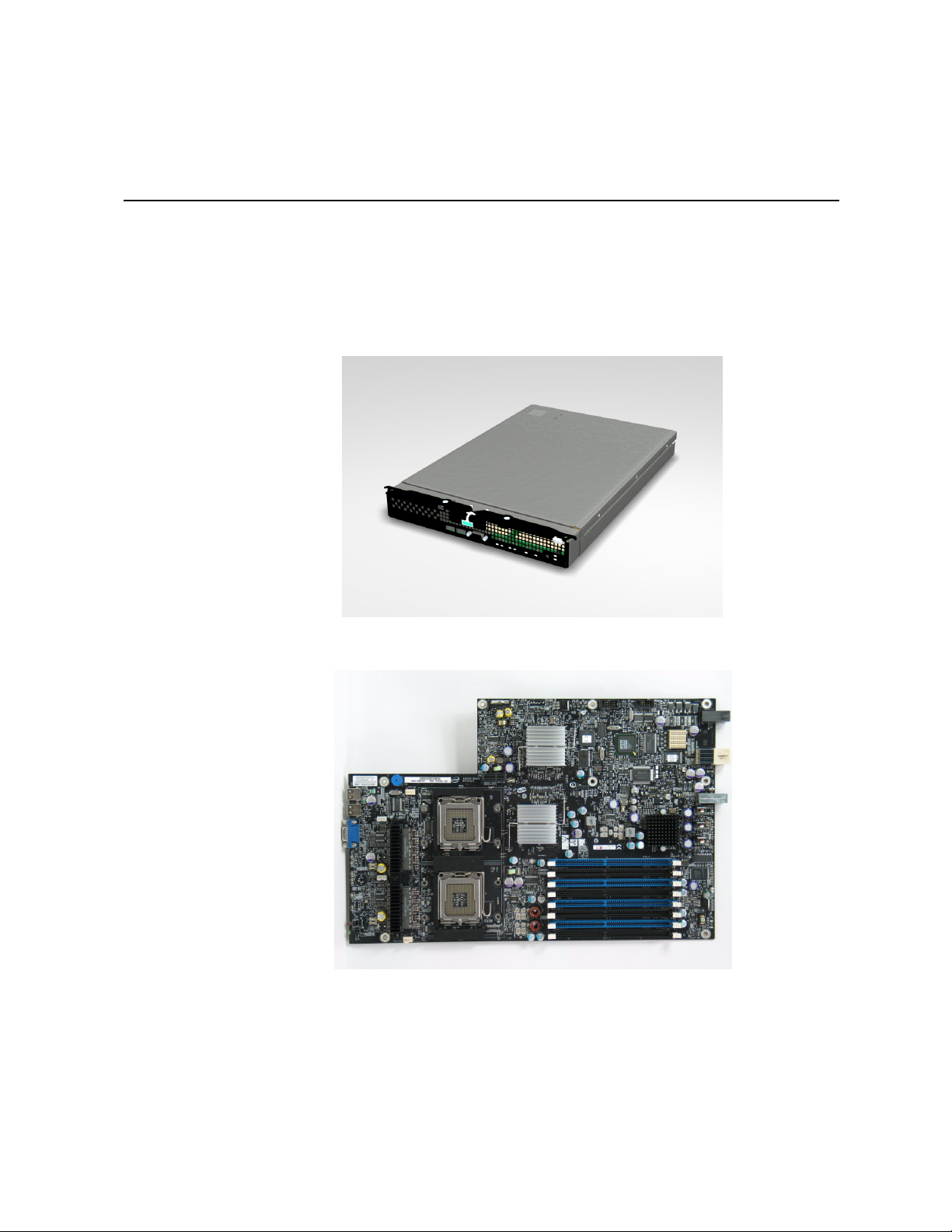
The Intel® Compute Module MFS5000SI is shown in the following pictures.
Figure 1. Intel® Compute Module MFS5000SI
Figure 2.
Server Board
Intel® Compute Module MFS5000SI User Guide 1
Page 14

The following table summarizes the major features of the server board.
Table 1. Compute Module Features
Feature Description
®
Processors Support for up to two Dual-Core Intel
Memory Support for up to 32 GB of fully-buffered DDR2 667-MHz DIMMs (FB-DIMM)
Eight DIMM slots
Support for DIMM sparing and memory mirroring
Chipset Intel® 5000P chipset, consisting of:
Xeon® processors 5000 sequence
• Intel® 5000P Memory Controller Hub (MCH)
• Intel® 6321ESB I/O Controller Hub
Peripheral Interfaces External connections:
• Two USB 2.0 ports
• Video connector
Internal connections:
• One connector to the chassis I/O mezzanine card
Video ATI* ES1000 controller with 16MB onboard memory
Hard Drive LSI* 1064e SAS controller
LAN Intel® 8256EB dual port controller
Trusted Computing Trusted Platform Module, version 1.2
2 Intel® Compute Module MFS5000SI User Guide
Page 15
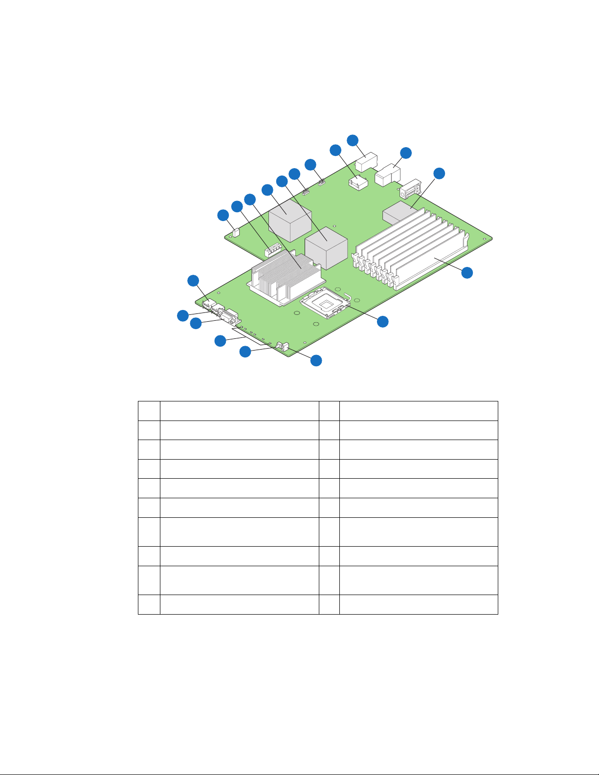
Connector and Component Locations
B
A
S
R
Q
P
O
N
M
C
D
L
E
K
J
F
I
H
G
AF002219
A Mezzanine Card Connector K USB2 Port
B Midplane Power Connector L USB1 Port
C Midplane Signal Connector M CMOS Battery
D SAS Connector N Test Connector (manufacturing only)
E FBDIMM Slots O CPU #2 Heatsink
F CPU1 Socket P Intel® 6321ESB I/O Controller Hub
G Power/Fault LEDs Q Intel® 5000P Memory Controller Hub
H Power Switch R Test Connector (manufacturing only)
(MCH)
I Activity and ID LEDs S Serial Debug Connector
(manufacturing only)
J Video Connector
Figure 3. Component and Connector Locations
Intel® Compute Module MFS5000SI User Guide 3
Page 16
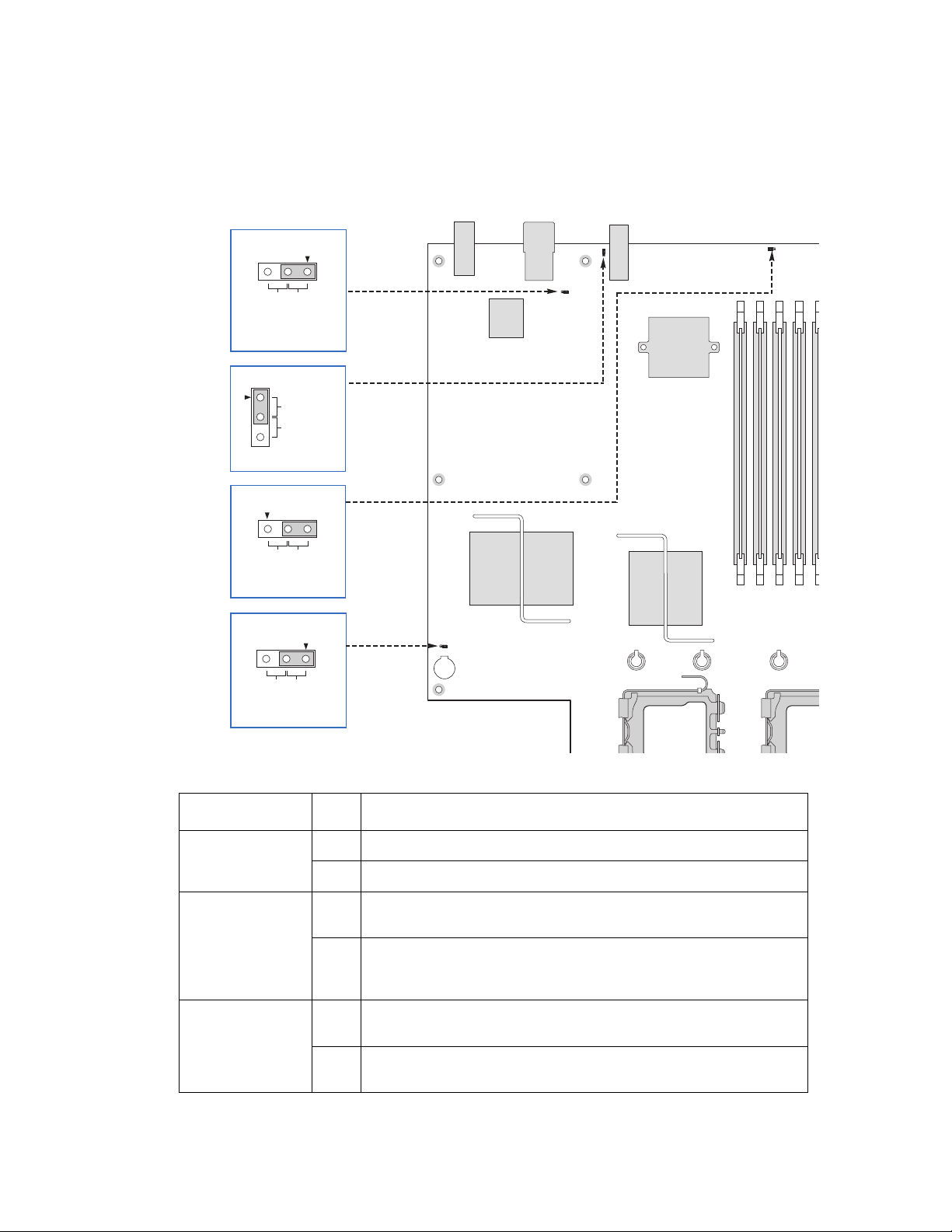
Configuration Jumpers
Fi
BIOS Bank Select
32
Default BOOT FROM
EMERGENCY
BIOS IMAGE
J3A3
PASSWORD CLR
Default
2
CLEAR
PASSWORD
3
J4A1
BMC Force Update
3
2
Default
Enabled
Disabled
J7A1
CMOS CLR
32
DefaultCLEAR
CMOS
J1F2
AF002220
Figure 4. Configuration Jumper Locations
Jumper Name Pins What happens at system reset…
J7A1: BMC Force
Update
J4A1: Password
Clear
J1F2: CMOS
Clear
1-2 BMC Firmware Force Update Mode - Enabled
2-3 BMC Firmware Force Update Mode - Disabled (Default)
1-2 These pins should have a jumper in place for normal system operation
(Default)
2-3 If these pins are jumpered, administrator and user passwords will be
cleared immediately. These pins should not be jumpered for normal
operation.
1-2 These pins should have a jumper in place for normal system
operation. (Default)
2-3 If these pins are jumpered, the CMOS settings will be cleared
immediately. These pins should not be jumpered for normal operation.
4 Intel® Compute Module MFS5000SI User Guide
Page 17
J3A3: BIOS Bank
8
Select
1-2 If these pins are jumpered, the BIOS will be forced to boot from the
lower bank. These pins should not be jumpered for normal operation.
2-3 These pins should have a jumper in place for normal system
operation. (Default)
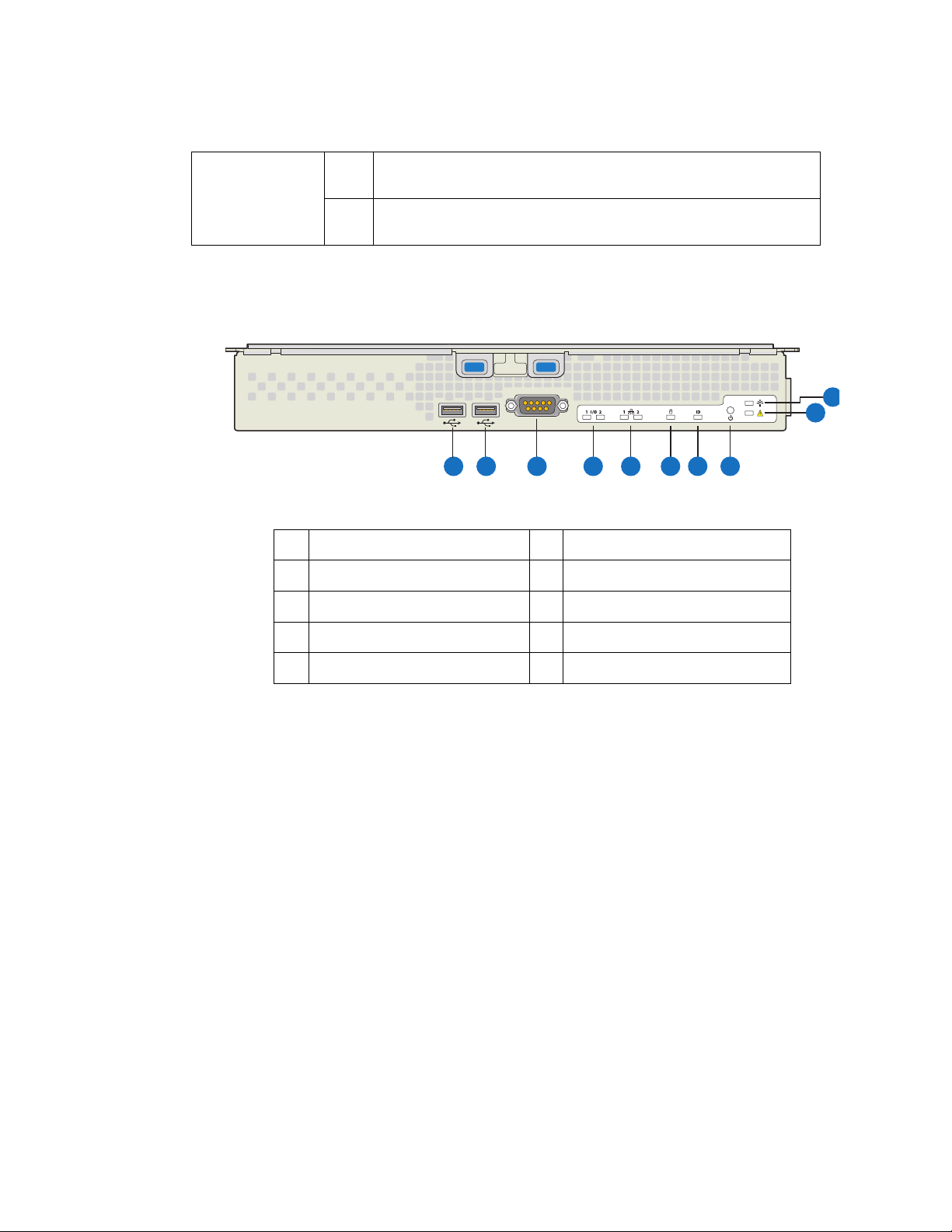
Front Panel Connectors and Indicators
B
A
A USB1 Port B USB2 Port
C Video Connector D I/O 1 and I/O 2 Activity LEDs
E NIC1 and NIC2 Activity LEDs F Drive Activity LED
GID LED HPower Button
C
J
I
D
F
E
G
H
AF00240
I Fault LED J Power LED
Figure 5. Front Panel Connectors and Indicators
Hardware Requirements
To avoid integration difficulties and possible board damage, your system must meet the
requirements outlined below.
Processor
The Intel® Compute Module MFS5000SI supports up to two Multi-Core Intel® Xeon®
Processors 5xxx Series.
Memory
A minimum of two fully-buffered DDR2 667 MHz DIMM(s) (FB-DIMM) should be
installed. Additional DIMMs must be installed in pairs, up to eight total.
Intel® Compute Module MFS5000SI User Guide 5
Page 18

Power Supply
A minimum of one 1000-Watt power supply is required to turn on a compute module.
One power supply will support 1 compute module plus all other modules in the system.
Two power supplies will support 2 to 3 compute modules (in any slot) plus all other
modules in the system.
Three power supplies will support 4 to 6 compute modules (in any slot) plus all other
modules in the system.
Any additional power supplies above minimum required (based on configuration)
provides redundancy.
6 Intel® Compute Module MFS5000SI User Guide
Page 19

2 Hardware Installations and
Upgrades
Before You Begin
Before working with your server product, review the safety and ESD information at the
beginning of this manual and in the appendices.
Tools and Supplies Needed
• Phillips
• 1/4-inch nut driver
• Needle-nosed pliers
• Ant-static wrist strap and conductive foam pad (recommended)
*
(cross head) screwdriver (#1 bit and #2 bit
Installation Guidelines
Before installing options:
1. Observe the safety and ESD information at the beginning of this manual and in the
appendices.
2. Remove the compute module from the chassis; before doing so, you must first shut
down the operating system and turn off the compute module. You do not have to shut
down the chassis.
3. Blue on a component indicates a touch point, where you can grip the component to
install or remove it from the server.
4. Green on a component indicates that the component may be hot-swapped. See the
instructions included with the hot-swap component for a complete list of installation
or removal steps.
Removing and Installing an Intel® Compute Module
MFS5000SI
Removing a Compute Module from the Server System
1. Observe the safety and ESD information at the beginning of this manual and in the
appendices.
2. If the compute module is operating, shut down the operating system and power it
down.
Intel® Compute Module MFS5000SI User Guide 7
Page 20

3. Release the two retention levers by pressing on the release button located between the
two lever handles.
4. Rotate the two lever handles outward and pull the compute module from the chassis
slot.
5. Place either a filler or another compute module into the bay within one minute; this
step is required to maintain proper airflow patterns throughout the server system and
to ensure proper system cooling.
Installing a Compute Module into the Server System
1. Observe the safety and ESD information at the beginning of this manual and in the
appendices
2. If you have not done so already, install any necessary options, such as processors,
memory, hard drives and expansion cards in the compute module.
Note: The top cover is a required component of the compute module; do not attempt
to insert a compute module into a server system without a top cover installed.
3. Make sure the retention levers on the compute module are in the open position.
4. Insert the compute module into an open slot in the system and slide it in until it stops.
5. Close the retention lever handles on the front of the compute module.
Opening and Closing the Top Cover
Opening and Removing the Top Cover
1. Observe the safety and ESD information at the beginning of this manual and in the
appendices
2. If the compute module is installed in a server system, see “Removing a Compute
Module from the Server System” on page 7 for removal instructions.
3. Carefully lay the compute module down on a flat, non-conductive surface, with the
cover side up.
8 Intel® Compute Module MFS5000SI User Guide
Page 21
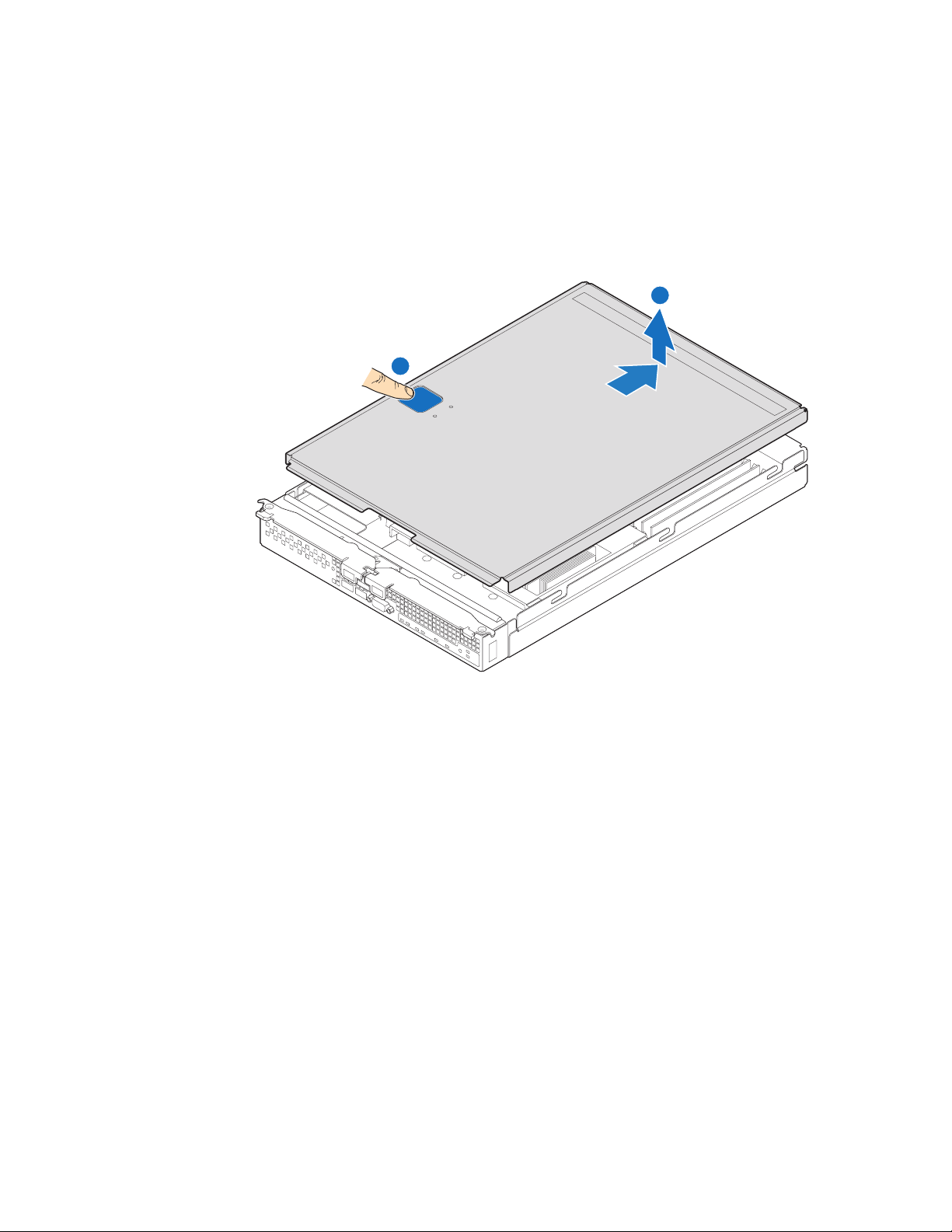
4. Press the top cover release button (see letter “A” in the following figure) and slide the
top cover back, away from the compute module bezel (see letter “B”). Lift the top
cover up and off the compute module.
Caution: Always replace the top cover before installing the compute module into a
server system.
B
A
1
I/O
2
1
2
ID
Figure 6. Removing Top Cover
AF002402
Intel® Compute Module MFS5000SI User Guide 9
Page 22
Replacing and Closing the Top Cover
1. Observe the safety and ESD information at the beginning of this manual and in the
appendices
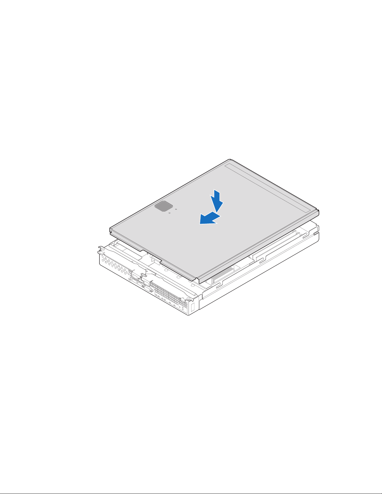
2. Place the top cover on the compute module so that it engages the cover guide notches.
Note: Before closing the top cover, check that all components are installed and
seated correctly and that no loose tools or parts are inside the compute
module.
Slide the top cover forward to the closed position until the retention latch fully
engages.
1
I/O
2
1
2
ID
AF002403
Figure 7. Installing Top Cover
10 Intel® Compute Module MFS5000SI User Guide
Page 23
Installing or Replacing a Processor
Caution: Only processors validated for use in the Intel® Compute Module MFS5000SI should be
installed. You may damage the compute module if an inappropriate processor is installed.
Installing a Processor
1. Observe the safety and ESD information at the beginning of this manual and in the
appendices.
2. If the compute modulecompute module is installed in a server system, see “Removing
a Compute Module from the Server System” on page 7 for removal instructions.
3. Remove the top cover. For instructions, see “Opening and Removing the Top Cover”
on page 8.
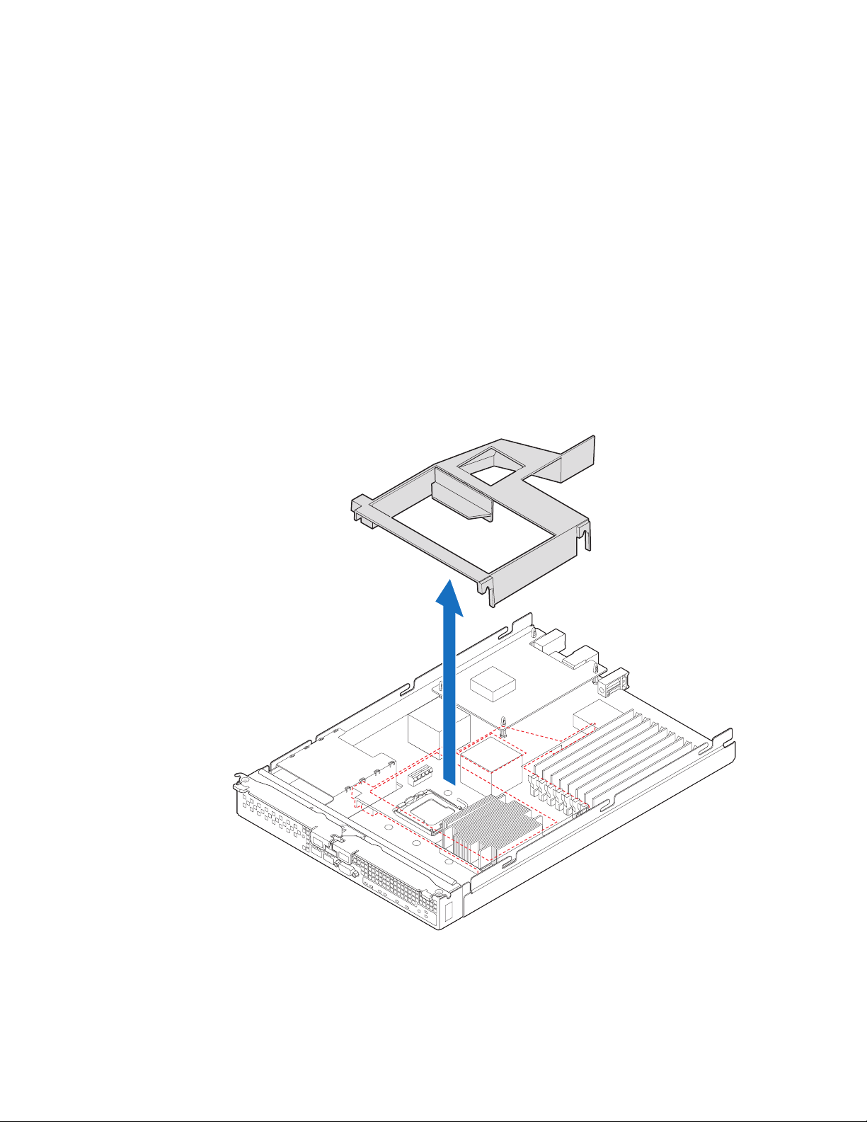
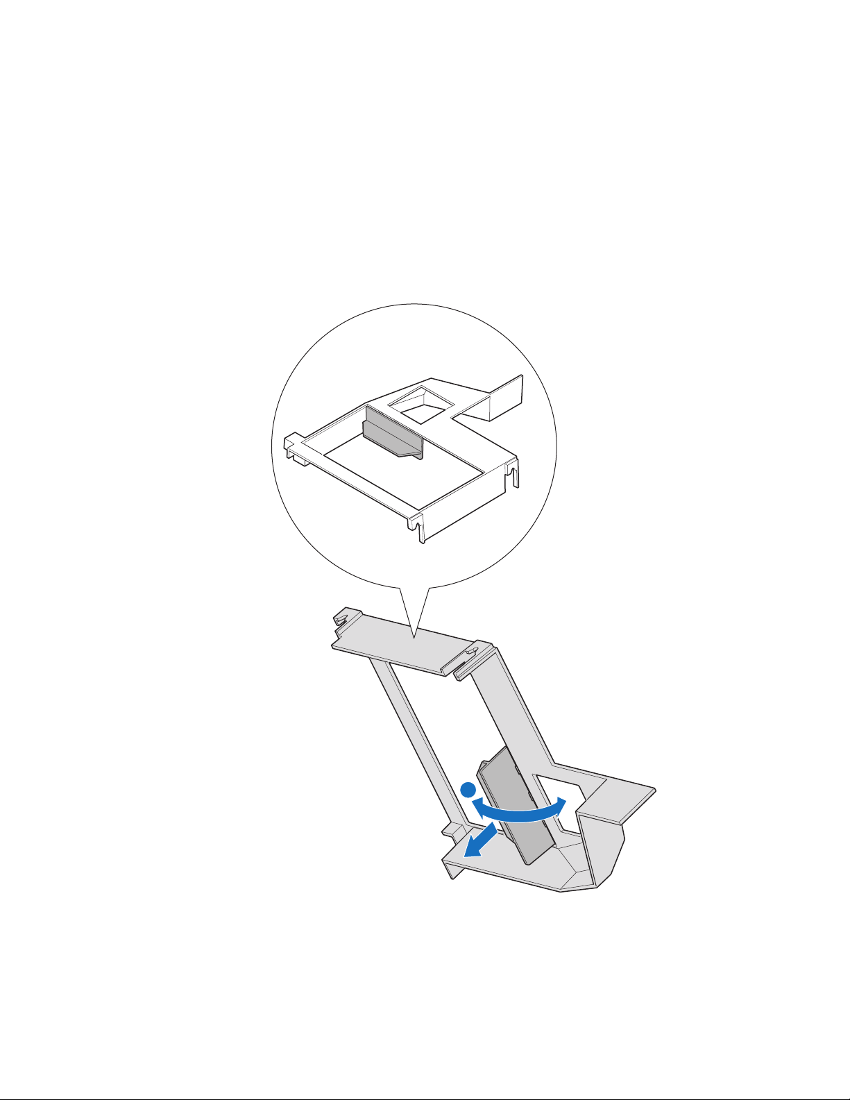
4. Remove the processor air duct.
1
I/O
2
1
2
ID
AF002404
Figure 8. Removing Processor Air Duct
Intel® Compute Module MFS5000SI User Guide 11
Page 24
5. Locate the processor socket. Push the lever handle down and away from the socket to
release it. Fully raise the socket handle.
TP02074
Figure 9. Lifting Processor Socket Handle
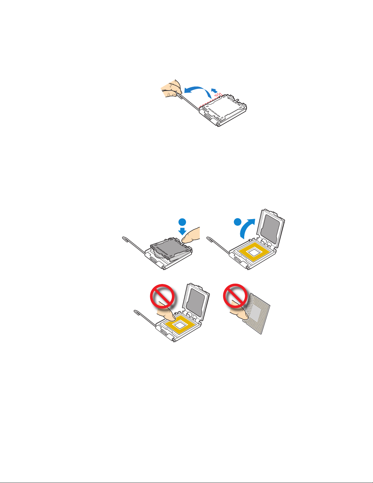
6. Push the rear tab of the load plate with your finger tip (see letter “A” in the following
figure) to bring the front end of the load plate up slightly. Open the load plate (see
letter “B”).
Note: Do not touch the socket pins; they are very sensitive and easily damaged.
A
B
Figure 10. Opening Load Plate
TP02075
12 Intel® Compute Module MFS5000SI User Guide
Page 25
7. If present, remove the protective shipping cover from the processor.
AF002222
Figure 11. Removing Protective Shipping Cover
8. Orient the processor with the processor socket so that the processor cut-outs match the
socket notches (see letter “A” in the following figure). Install the processor (see letter
“B”).
Caution: The underside of the processor has components that may damage the
socket pins if installed improperly. Processor must align correctly with
socket opening before installation. DO NOT DROP processor into socket.
A
B
3
AF00222
Figure 12. Orienting and Installing Processor
Intel® Compute Module MFS5000SI User Guide 13
Page 26
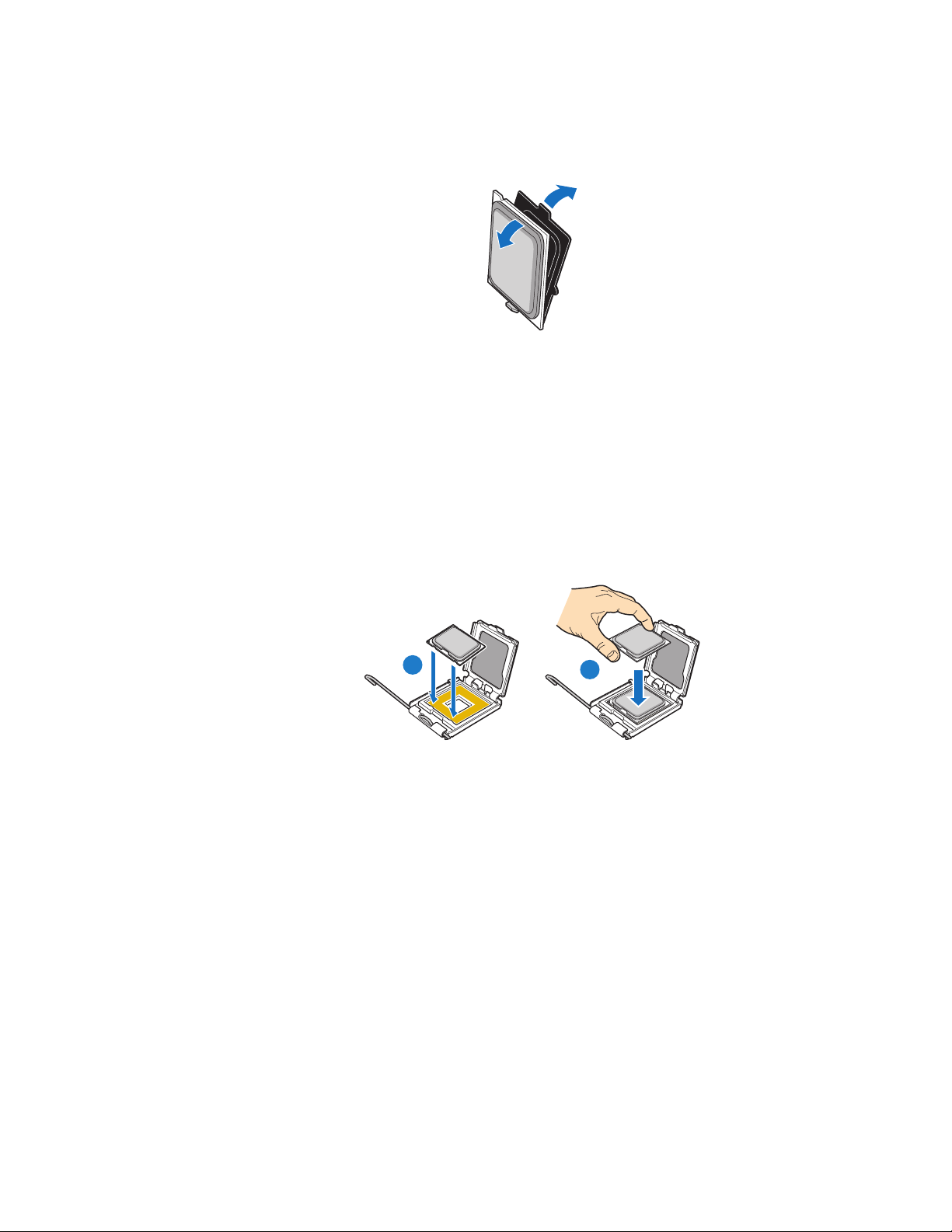
9. Remove the socket protective cover. Grasp the socket protective cover tab and pull
away from the load plate (see letter “A” in the following figure). Remove the socket
protective cover (see letter “B”) and store for future use.
Note: Retain the socket protective cover for later use when removing a processor
that will not be replaced.
A
B
TP02076
Figure 13. Removing Socket Protective Cover
10. Lower the processor load plate (see letter “A” in the following figure). With your
finger, push down on the load plate (see letter “B”). Lower the socket lever until it is
fully latched (see letter “C”).
C
A
B
AF002224
Figure 14. Lowering Load Plate and Socket Lever
11. Ensure that the thermal material is intact on the bottom of the heatsink.
12. Align the heatsink over the processor, thermal material side down, with the captive
screws in line with the holes on the heatsink retention module. Press down firmly on
the heatsink.
14 Intel® Compute Module MFS5000SI User Guide
Page 27
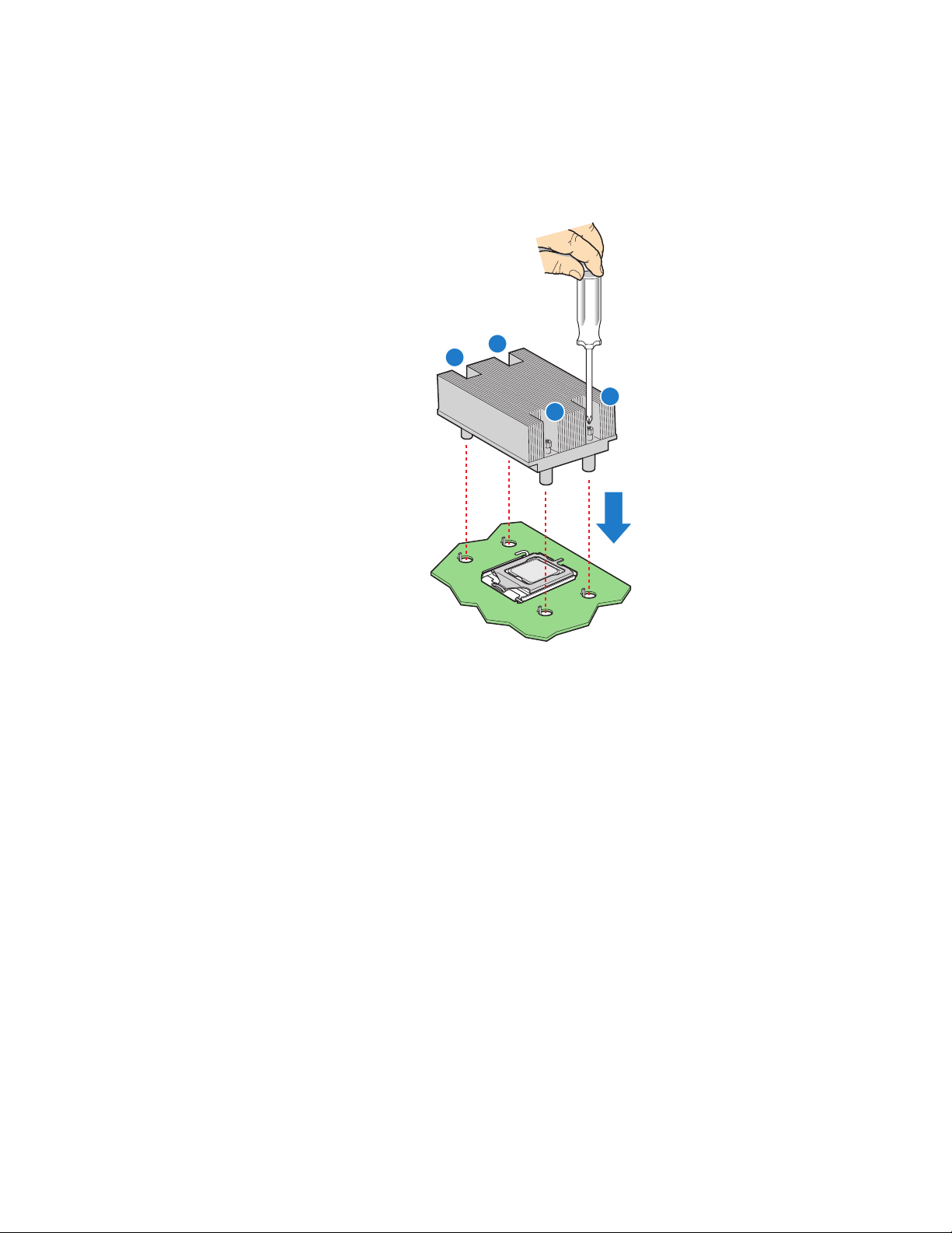
13. Press firmly on the captive screws and tighten them, alternating between screws in a
diagonal manner (see tightening order in the following figure). Do not over-tighten
the screws by using excessive force.
3
2
1
4
TP02328
Figure 15. Installing Heatsink
Intel® Compute Module MFS5000SI User Guide 15
Page 28
14. If you are installing a second processor then the second processor air baffle must be
removed to ensure proper cooling for two processors.
Caution: This step only applies if your system has TWO processors. For a one-
processor configuration, the second processor air baffle must remain in
place to ensure proper cooling.
Remove the second processor air baffle by rocking the air baffle back and forth until it
breaks off (see letter “A” in the following figure).
A
AF002410
Figure 16. Removing Second Processor Air Baffle
16 Intel® Compute Module MFS5000SI User Guide
Page 29
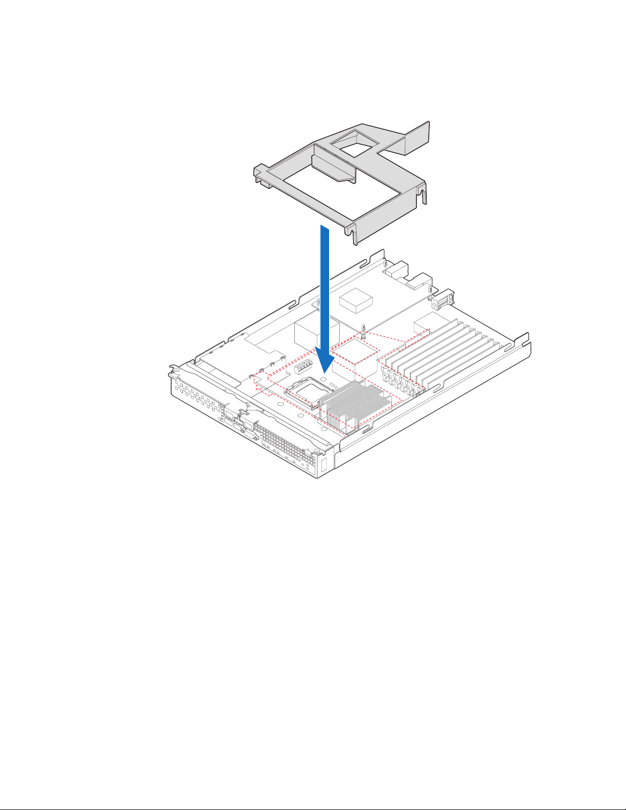
15. Reinstall the processor air duct.
1
I/O 2
1
2
ID
AF002405
Figure 17. Reinstalling Processor Air Duct
16. Reinstall the top cover. For instructions, see “Replacing and Closing the Top Cover”
on page 10.
17. Reinstall the server compute blade in the server system. For instructions, see
“Installing a Compute Module into the Server System” on page 8.
Intel® Compute Module MFS5000SI User Guide 17
Page 30
Replacing a Processor
1. Observe the safety and ESD information at the beginning of this manual and in the
appendices.
2. If the compute module is installed in a server system, see “Removing a Compute
Module from the Server System” on page 7 for removal instructions.
3. Remove the top cover. For instructions, see “Opening and Removing the Top Cover”
on page 8.
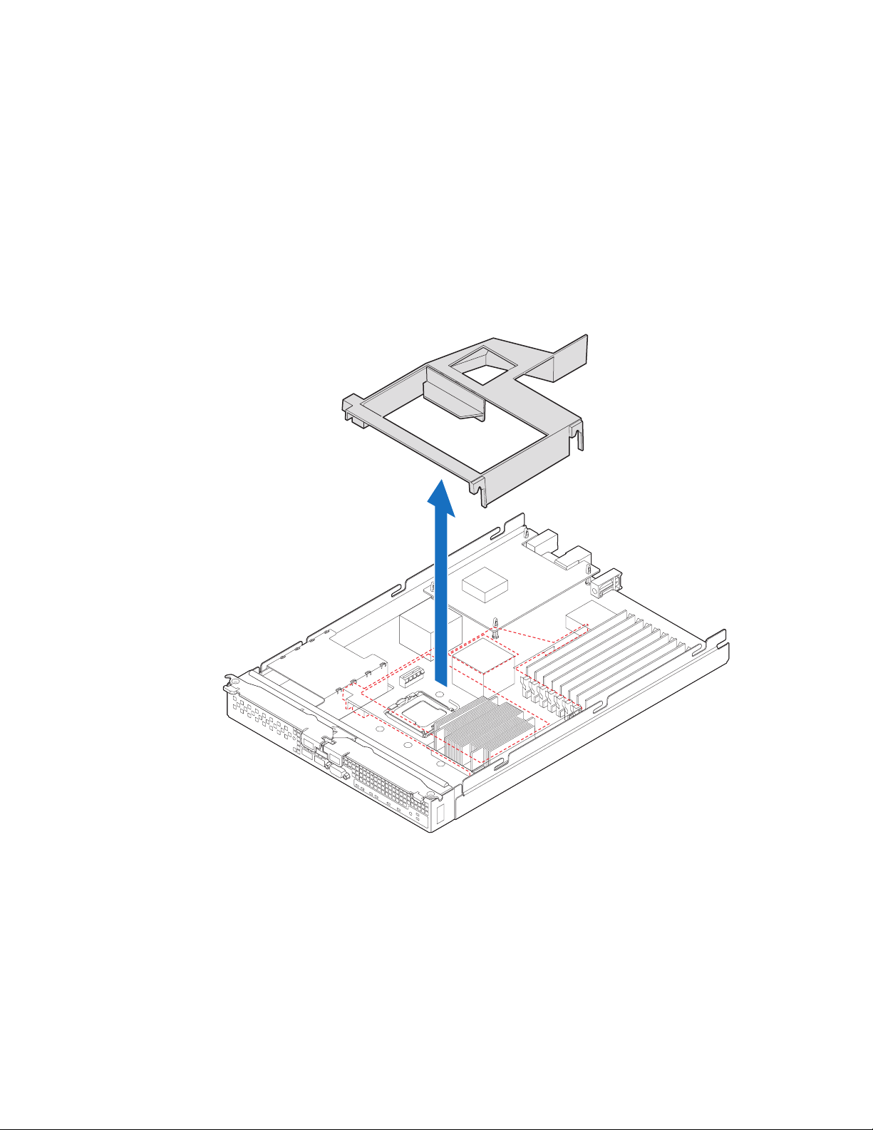
4. Remove the processor air duct.
1
I/O 2
1
2
ID
AF002404
Figure 18. Removing Processor Air Duct
18 Intel® Compute Module MFS5000SI User Guide
Page 31

5. Carefully remove the processor heatsink by fully loosening the captive screws on the
heatsink, and then gently lifting the heatsink off the processor.
3
2
1
4
AF002221
Figure 19. Removing the Heatsink
6. Push the lever handle down and away from the socket to release it. Fully raise the
socket handle.
TP02074
Figure 20. Lifting Processor Socket Handle
Intel® Compute Module MFS5000SI User Guide 19
Page 32

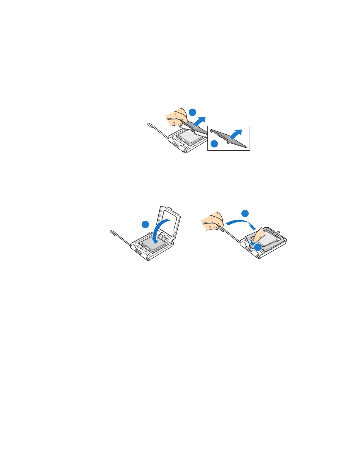
7. Push the rear tab of the load plate with your finger tip (see letter “A” in the following
figure) to bring the front end of the load plate up slightly. Open the load plate (see
letter “B”).
A
B
TP02075
Figure 21. Opening Load Plate
8. Remove processor.
Note: Do not touch the socket pins; they are very sensitive and easily damaged.
AF002225
Figure 22. Removing Processor
20 Intel® Compute Module MFS5000SI User Guide
Page 33

9. If present, remove the protective shipping cover from the replacement processor.
AF002222
Figure 23. Removing Protective Shipping Cover
10. Orient the replacement processor with the processor socket so that the processor cutouts match the socket notches (see letter “A” in the following figure). Install the
replacement processor (see letter “B”).
Caution: The underside of the processor has components that may damage the
socket pins if installed improperly. Processor must align correctly with
socket opening before installation. DO NOT DROP processor into socket.
A
B
3
AF00222
Figure 24. Orienting and Installing Processor
11. Lower the processor load plate (see letter “A” in the following figure). With your
finger, push down on the load plate (see letter “B”). Lower the socket lever until it is
fully latched (see letter “C”).
C
A
B
AF002224
Figure 25. Lowering Load Plate and Socket Lever
Intel® Compute Module MFS5000SI User Guide 21
Page 34

12. Ensure that the thermal material is still intact on the bottom of the heatsink.
13. Align the heatsink over the processor, thermal material side down, with the captive
screws in line with the holes on the heatsink retention module. Press down firmly on
the heatsink.
14. Press firmly on the captive screws and tighten them, alternating between screws in a
diagonal manner (see tightening order in the following figure). Do not over-tighten
the screws by using excessive force.
3
2
1
4
TP02328
Figure 26. Re-installing Heatsink
22 Intel® Compute Module MFS5000SI User Guide
Page 35

15. Reinstall the processor air duct.
1
I/O 2
1
2
ID
AF002405
Figure 27. Reinstalling Processor Air Duct
16. Reinstall the top cover. For instructions, see “Replacing and Closing the Top Cover”
on page 10.
17. Reinstall the server compute blade in the server system. For instructions, see
“Installing a Compute Module into the Server System” on page 8.
Intel® Compute Module MFS5000SI User Guide 23
Page 36

Installing and Removing Memory Modules
Supported Memory
The server board provides support for eight DDR2-667 fully-buffered DIMM sockets
across two branches. Each branch has two channels. Channel A consists of slots A1 and
A2; channel B consists of slots B1 and B2; channel C consists of slots C1 and C2; and
channel D consists of slots D1 and D2.
DIMMs must be populated in pairs across consecutive channels starting with the lowest
numbered slot in each channel. Slots A1 and B1 are paired, followed by slots C1 and D1.
For performance reasons, when configuring four DIMMs, DIMM pair A2 and B2 should
never be populated before DIMM pair C1 and D1. A four-DIMM configuration should be
populated as A1 and B1; C1 and D1.
In non-mirrored mode, all DIMMs with the same slot number within a given branch must
match (size, technology, manufacturer). It is not required to match DIMMs between
different slot numbers.
DIMMs must meet the following requirements:
• Use only fully-buffered DIMMs (FB-DIMMs) with DDR2 DRAM technology.
• Use only DDR2-667 stacked FB-DIMM modules.
In determining your memory requirements, the need for memory sparing or memory
mirroring must be considered.
Memory Sparing and Mirroring
The chipset includes hardware that supports memory mirroring and memory on-line
sparing. Both memory mirroring and memory on-line sparing provide a way to prevent
data loss in case a DIMM fails.
With memory mirroring the system maintains two copies of all data in the memory
subsystem. If a DIMM fails, the data is not lost because the second copy of the data is
available from the mirrored DIMM in the opposite channel. The system will not fail due
to memory error unless both the primary and the mirrored copy of the data become corrupt
at the same time.
In a mirrored system, the maximum usable memory is one-half of the installed memory,
with a minimum of four DIMMs installed. Since the data is duplicated across DIMMs, it
means that up to one-half of the installed DIMMs are actively in use at any one time. The
remaining DIMMs are used for mirroring.
Memory mirroring and memory sparing are mutually exclusive. Only one can be active at
a time. See the Intel® Compute Module MFS5000SI Technical Product Specification for
additional information regarding the memory sub-system.
24 Intel® Compute Module MFS5000SI User Guide
Page 37

Installing DIMMs
DIMM slots are numbered as follows:
DIMM B2
DIMM B1
DIMM A2
DIMM A1
DIMM Sockets
DIMM C1
Branch 1Branch 0
Figure 28. DIMM Slot Order
Populate DDR2 FBDIMMs in the following order:
1. A1, B1, C1, D1, then
2. A2, B2, C2, D2
To install DIMMs:
DIMM C2
DIMM D1
DIMM D2
AF002452
1. Observe the safety and ESD information at the beginning of this manual and in the
appendices.
2. If the compute module is installed in a server system, see “Removing a Compute
Module from the Server System” on page 7 for removal instructions.
3. Remove the top cover. For instructions, see “Opening and Removing the Top Cover”
on page 8.
Intel® Compute Module MFS5000SI User Guide 25
Page 38

4. Remove the processor air duct.
1
I/O 2
1
2
ID
Figure 29. Removing Processor Air Duct
5. Locate the DIMM sockets.
6. Holding the DIMM by the edges, remove it from it’s packaging.
AF002404
26 Intel® Compute Module MFS5000SI User Guide
Page 39

7. Open both DIMM socket levers (see letter “A” in the following figure). Position the
DIMM above the socket, taking care to align the two small notches in the bottom of
the DIMM with the keys in the DIMM socket (see letter “B”). Insert the bottom edge
of the DIMM into the socket and press down on the top edge of the DIMM (see letter
“C”) until the DIMM is fully seated and the retaining clips (see letter “D”) are locked
firmly into place.
Important: Visually check that each latch is fully closed and correctly engaged with
each DIMM edge slot.
C
D
A
AF002453
Figure 30. Installing DIMMs
B
Intel® Compute Module MFS5000SI User Guide 27
Page 40

8. Reinstall the processor air duct.
1
I/O 2
1
2
ID
AF002405
Figure 31. Reinstalling Processor Air Duct
9. Reinstall the top cover. For instructions, see “Replacing and Closing the Top Cover”
on page 10.
10. Reinstall the server compute blade in the server system. For instructions, see
“Installing a Compute Module into the Server System” on page 8.
28 Intel® Compute Module MFS5000SI User Guide
Page 41

Removing DIMMs
To remove DIMMs:
1. Observe the safety and ESD information at the beginning of this manual and in the
appendices.
2. If the compute module is installed in a server system, see “Removing a Compute
Module from the Server System” on page 7 for removal instructions.
3. Remove the top cover. For instructions, see “Opening and Removing the Top Cover”
on page 8.
4. Remove the processor air duct.
1
I/O
2
1
2
ID
AF002404
Figure 32. Removing Processor Air Duct
Intel® Compute Module MFS5000SI User Guide 29
Page 42

5. Locate the DIMM socket and gently open the retaining clips at each end of the socket
(see letter “A” in the following figure). This will slightly lift the DIMM from its
socket. Holding the DIMM by the edges, remove it from the socket (see letter “B”).
Important: Store the removed DIMM in an anti-static package.
B
A
AF002454
Figure 33. Removing DIMMs
30 Intel® Compute Module MFS5000SI User Guide
Page 43

6. Reinstall the processor air duct.
1
I/O 2
1
2
ID
AF002405
Figure 34. Reinstalling Processor Air Duct
7. Reinstall the top cover. For instructions, see “Replacing and Closing the Top Cover”
on page 10.
8. Reinstall the server compute blade in the server system. For instructions, see
“Installing a Compute Module into the Server System” on page 8.
Intel® Compute Module MFS5000SI User Guide 31
Page 44

Installing and Removing Mezzanine Card
Installing the Mezzanine Card
1. Observe the safety and ESD information at the beginning of this manual and in the
appendices.
2. If the compute module is installed in a server system, see “Removing a Compute
Module from the Server System” on page 7 for removal instructions.
3. Remove the top cover. For instructions, see “Opening and Removing the Top Cover”
on page 8.
4. Holding the mezzanine card by its edges, remove it from the packaging. Remove the
protective connector cover from the mezzanine card.
5. Locate the mezzanine card socket on the server board.
6. With a Phillips* screwdriver, remove four screws from the server board.
1
1
I/O
I/O
2
2
1
1
2
2
ID
ID
AF002456
Figure 35. Removing Screws from Server Board
32 Intel® Compute Module MFS5000SI User Guide
Page 45

7. With a 1/4-inch nut driver, install the four standoffs that shipped with the mezzanine
card.
1
I/O 2
1
2
ID
Figure 36. Installing Standoffs for Mezzanine Card
AF002457
Intel® Compute Module MFS5000SI User Guide 33
Page 46

8. Position the mezzanine card above the mezzanine card socket and align the four screw
holes with the standoffs taking care to position the connector housing on the
mezzanine card with the connector on the server board. Carefully press the mezzanine
card into place until it is fully seated in the socket and resting on the standoff supports.
1 I/O
2
1
2
ID
AF002407
Figure 37. Installing Mezzanine Card
34 Intel® Compute Module MFS5000SI User Guide
Page 47

9. Secure the mezzanine card to the standoffs with the four screws previously removed.
1
1
I/O 2
I/O
Figure 38. Securing Mezzanine Card to Standoffs
10. Reinstall the top cover. For instructions, see “Replacing and Closing the Top Cover”
on page 10.
11. Reinstall the server compute blade in the server system. For instructions, see
“Installing a Compute Module into the Server System” on page 8.
Removing a Mezzanine Card
1. Observe the safety and ESD information at the beginning of this manual and in the
appendices.
2. If the compute module is installed in a server system, see “Removing a Compute
Module from the Server System” on page 7 for removal instructions.
3. Remove the top cover. For instructions, see “Opening and Removing the Top Cover”
on page 8.
2
1
1
2
2
ID
ID
AF002458
Intel® Compute Module MFS5000SI User Guide 35
Page 48

4. Locate the mezzanine card. With a Phillips* screwdriver, remove the four screws
securing the mezzanine card to the standoffs.
1 I/O
1
I/O
2
2
1
1
2
2
ID
ID
Figure 39. Removing Screws from Mezzanine Card
AF002458
36 Intel® Compute Module MFS5000SI User Guide
Page 49

5. Holding the mezzanine card by its edges, gently lift it from the socket and store it in
an anti-static package.
1 I/O
2
1
2
ID
Figure 40. Removing Mezzanine Card
AF002406
Intel® Compute Module MFS5000SI User Guide 37
Page 50

6. With a 1/4-inch nut driver, remove the standoffs.
1
I/O
2
1
2
ID
AF002457
Figure 41. Removing Standoffs
7. With a Phillips* screwdriver, secure the four screws previously removed into the
holes vacated by the standoffs.
8. Reinstall the top cover. For instructions, see “Replacing and Closing the Top Cover”
on page 10.
9. Reinstall the server compute blade in the server system. For instructions, see
“Installing a Compute Module into the Server System” on page 8.
38 Intel® Compute Module MFS5000SI User Guide
Page 51

Replacing the CMOS Battery
The lithium battery on the server board powers the RTC for up to 10 years in the absence
of power. When the battery starts to weaken, it loses voltage, and the server settings stored
in the CMOS RAM (for example, the date and time) may be wrong. Contact your
customer service representative or dealer for a list of approved replacement batteries.
Warni n g: Danger of explosion if battery is incorrectly replaced. Replace only with the same or
equivalent type recommended by the equipment manufacturer. Discard used batteries
according to manufacturer’s instructions.
Advarsel: Lithiumbatteri - Eksplosionsfare ved fejlagtig håndtering. Udskiftning må kun ske med
batteri af samme fabrikat og type. Levér det brugte batteri tilbage til leverandøren.
Advarsel: Lithiumbatteri - Eksplosjonsfare. Ved utskifting benyttes kun batteri som anbefalt av
apparatfabrikanten. Brukt batteri returneres apparatleverandøren.
Va r ni n g : Explosionsfara vid felaktigt batteribyte. Använd samma batterityp eller en ekvivalent typ
som rekommenderas av apparattillverkaren. Kassera använt batteri enligt fabrikantens
instruktion.
Varoitus: Paristo voi räjähtää, jos se on virheellisesti asennettu. Vaihda paristo ainoastaan
laitevalmistajan suosittelemaan tyyppiin. Hävitä käytetty paristo valmistajan ohjeiden
mukaisesti.
To replace the battery:
1. Observe the safety and ESD information at the beginning of this manual and in the
appendices.
2. If the compute module is installed in a server system, see “Removing a Compute
Module from the Server System” on page 7 for removal instructions.
3. Remove the top cover. For instructions, see “Opening and Removing the Top Cover”
on page 8.
Intel® Compute Module MFS5000SI User Guide 39
Page 52

4. Locate the DMOS battery (see letter “A” in the following figure).
A
AF002455
Figure 42. CMOS Battery Location
5. Insert the tip of a small flat-head screwdriver, or equivalent, under the tab in the
plastic retainer. Gently push down on the screwdriver to lift the battery.
6. Remove the battery from its socket.
7. Dispose of the battery according to local ordinance.
8. Remove the new lithium battery from its package, and, being careful to observe the
correct polarity, insert it in the battery socket.
9. Replace the top cover. For instructions, see “Replacing and Closing the Top Cover”
on page 10.
10. Reinstall the server compute blade in the server system. For instructions, see
“Installing a Compute Module into the Server System” on page 8
11. Run Setup to restore the configuration settings to the RTC.
40 Intel® Compute Module MFS5000SI User Guide
Page 53

3 Troubleshooting
This chapter provides information to assist you in troubleshooting the Intel® Compute
Module MFS5000SI.
A common cause of server function issues is outdated BIOS and BMC firmware, and
outdated operating system level device drivers. Before performing extensive
troubleshooting steps, ensure that the system BIOS and BMC firmware code, and device
drivers are up to date.
One of the first steps to perform in troubleshooting a compute module is to reboot the
system; try resetting your system using one of the methods below.
To do this: Press:
Soft boot reset to clear the system memory and reload the operating
system.
Cold boot reset. Turn the system power off and then on. This clears
system memory, restarts POST, reloads the operating system, and halts
power to all peripherals.
First Steps Checklist
• Are the server system power LEDs on?
• Is the chassis properly connected to an AC power source?
• Are the power supplies fully seated in the chassis and the power cables fully seated in
the power supplies?
• Is the compute module fully seated in the chassis?
• Are the processors fully seated in their sockets on the server board?
• Are the installed memory modules fully seated in their sockets on the server board?
• If installed, is the add-in mezzanine card fully seated in the slot on the server board?
• Are all jumper settings on the server board correct?
• Are the configuration settings defined in the BIOS Setup correct?
<Ctrl+Alt+Del>
Power off/on
• Is the operating system properly loaded? Refer to the operating system
documentation.
• Are all device drivers properly installed?
• Are all installed components and the installed operating system listed in the Intel®
Compute Module MFS5000SI Tested Hardware and Operating System List?
Intel® Compute Module MFS5000SI User Guide 41
Page 54

Hardware Diagnostic Testing
This section provides a more detailed approach to identifying and correcting a hardware
problem.
1. Turn off the compute module.
2. Connect a keyboard and video monitor to the USB and video ports located on the
front of the compute module. Turn on the video monitor and set the brightness and
contrast controls to at least two thirds of the maximum range (see the documentation
supplied with your video display monitor).
3. Verify that the chassis power supplies are properly installed and connected to
grounded AC outlets, and the chassis power LEDs are on.
4. Turn on the compute module.
5. If the power LED does light, but will not boot the operating system from the hard
drive, attempt to boot the from a bootable disk in a USB floppy drive or a USB CDROM drive.
6. If the power LED does not light, see “Power LED Does Not Light” on page 43.”
7. If the system fails to boot and emits a series of patterned beeps, see “BIOS POST
Beep Codes” on page 46.
8. If one or more system error LEDs is illuminated, see ““Diagnostic LED Information”
on page 46 for a description of the LED and suggested corrective actions.
Specific Problems and Corrective Actions
This section provides possible solutions for the following problems:
• Power LED does not light
• No video display
• Characters on the screen appear distorted or incorrect
• No available storage
• Network problems
Try the solutions in the order given. If you cannot correct the problem, contact your
service representative or authorized dealer for additional help.
42 Intel® Compute Module MFS5000SI User Guide
Page 55

Power LED Does Not Light
Check the following:
• Did you press the power-on button?
• Is the system operating normally? If so, the power LED might be defective.
• Is the chassis power LED lit? If not, refer to the troubleshooting section of the server
system user guide for additional guidance.
• Is the compute module fully seated in the chassis?
No Video Display
Check the following:
• Is the power LED lit? If not, refer to “Power LED Does Not Light” on page 43.
• Verify that the video monitor is turned on and functioning properly.
• Verify that the brightness and contrast controls on the video monitor are properly
adjusted?
• Does this video monitor work correctly if plugged into a different system?
• Is the system emitting a series of patterned beeps? If so, refer to “BIOS POST Beep
Codes” on page 46.
• Verify that the installed processor(s) are validated for use in the compute module.
• If only a single processor is installed, verify that it is installed in the first processor
socket.
• Remove and re-seat the processor(s).
• Verify that the installed memory is validated for use in the compute module.
• Verify that the installed memory has been populated according to the system
requirements.
• Remove and re-seat the memory.
• Is the keyboard functioning? Test it by turning the “Num Lock” function on and off to
see if the Num Lock light is working.
• Is the onboard video controller enabled in the BIOS?
• Move the video, keyboard and mouse connections from the management module to
the connectors on the front of the compute module. Do you now get video display? If
so, test the server system management module.
Characters are Distorted or Incorrect
Check the following:
• Is the video monitor properly adjusted? See the manufacturer’s documentation for
operating instructions.
• Are the video signal cable and power cable connected properly?
Intel® Compute Module MFS5000SI User Guide 43
Page 56

• Does this video monitor work correctly if plugged into a different system?
• Move the video, keyboard and mouse connections from the management module to
the connectors on the front of the compute module. Does video display properly? If
so, test the chassis management module
No Available Storage
Check the following:
• Verify in the Intel® Modular Server Control GUI that virtual drive(s) are assigned to
the compute module.
• Ensure drive(s) assigned to the compute module are installed and operating properly.
• Make sure the installed drives are validated for use with the Intel® Modular Server
System MFSYS25. Refer to the Intel® Modular Server System MFSYS25 Tested
Hardware and Operating System List for validation information.
Cannot Connect to a Compute Module
• Ensure that the Ethernet switch module is properly installed, the power LED is lit, and
the error LED is not lit.
• If the switch module is configured for multiple VLANS, verify that the network cable
is securely attached to the correct switch port.
• Try a different network cable.
• Make sure you are using the correct and most current drivers.
• Make sure the operating system network settings are configured appropriately for the
network the server is physically connected to.
Diagnostics Pass but Connection Fails
• Make sure that an Ethernet switch is properly installed in the bay associated with the
network interface card.
• Verify that the network driver is configured properly within the operating system.
Controller Stops Working when a Mezzanine Card is Installed
•
Verify that the system BIOS and firmware, onboard network interface card firmware
and mezzanine card firmware are all current.
• Try re-seating the mezzanine card first, and then if possible, try installing the
mezzanine card in a different compute module.
Mezzanine Card Stops Working Without Apparent Cause
• Try re-seating the mezzanine card first, and then if possible, try installing the
mezzanine card in a different compute module.
• The network driver files may be corrupt or deleted. Try re-installing the drivers.
44 Intel® Compute Module MFS5000SI User Guide
Page 57

Problems with Newly Installed Application Software
Check the following:
• Make sure the system meets the minimum hardware requirements for the software.
See the software documentation.
• Make sure the software is properly installed and configured for the system. See the
software documentation.
• Use only an authorized copy. Unauthorized copies often do not work.
• If you are running the software from a diskette, CD-ROM or DVD-ROM, try a
different media.
• Make sure the correct device drivers are installed.
If the problems persist, contact the software vendor’s customer service representative.
Problems with Application Software that Previously Functioned
Properly
Check the following:
• Uninstall and reinstall the software. Make sure all necessary files are installed.
• If you suspect that a transient voltage spike, power outage, or brown-out might have
occurred, reload the software and try running it again. Symptoms of voltage spikes
include a flickering video display, unexpected system reboots, and the system not
responding to user commands.
Note: Random errors in data files: If you are getting random errors in your data files, they may
be getting corrupted by voltage spikes on your power line. If you are experiencing any of
the above symptoms that might indicate voltage spikes on the power line, you may want to
install a power conditioner between the power outlet and the system power cord.
Devices are Not Recognized within the Operating System
Operating systems include a limited set of device drivers by default. Ensure that you
install all necessary drivers at the time you install the operating system.
Intel® Compute Module MFS5000SI User Guide 45
Page 58

Diagnostic LED Information
The Intel® Compute Module MFS5000SI includes a number of diagnostic LEDs on the
front of the compute module that can aid in troubleshooting your system. The following
table lists these LEDs along with a usage description of each LED.
Table 2. Diagnostic LED Information
LED Name Function Color Indicator
Power LED Identifies power state of
system
Fault LED Identifies fault warning Amber Off = No Fault
ID LED Provides an aid in
identifying a compute
module from the front
panel
Drive activity
LED
NIC1—2 LEDs Indicates network activity
Indicates drive activity Green Off = No drive activity
and link
Green Off = Power is off
On = Power on
Slow Blink = Power is in
standby or sleeping mode
On = Critical error or nonrecoverable
Slow blink = Non-critical
Fast blink = Locate (when
device does not have an ID
LED)
Double blink = Degraded
state
Blue Use the Intel® Modular
Server Control software to
activate or inactivate the
LED.
Blink = Drive activity
Green Blink = Outbound activity
I/O 1 - I/O 2
Activity LEDs
Indicates network activity
and link of NICs on I/O
mezzanine card
Green Off = No link
On = Link established
Blink = Activity
BIOS POST Beep Codes
At the beginning of the server boot-up process, the BIOS runs a power-on self test (POST)
routine to check various system components for proper function. Prior to system video
initialization, if POST encounters a fatal system error, such as a processor problem,
memory problem or video controller problem, the BIOS will trigger a series of patterned
beep codes to indicate the error conditions.
46 Intel® Compute Module MFS5000SI User Guide
Page 59

The following table contains a partial list of the POST error beep codes enabled for the
Intel® Compute Module MFS5000SI. The beep code sounds only when a critical error
occurs or when the BIOS fails to boot to the operating system. Please note that not all
error conditions are supported by BIOS beep codes.
Table 3. POST Error Beep Codes
Beeps Error Message Description
3 Memory error System halted because a fatal error related to the
6 BIOS rolling back
error
memory was detected.
System has detected a corrupted BIOS in the flash part
and is rolling back to the last good BIOS.
Intel® Compute Module MFS5000SI User Guide 47
Page 60

48 Intel® Compute Module MFS5000SI User Guide
Page 61

A Getting Help
World Wide Web
http://support.intel.com/support/motherboards/server/blade.htm
Telephone
All calls are billed US $25.00 per incident, levied in local currency at the applicable credit
card exchange rate plus applicable taxes. (Intel reserves the right to change the pricing for
telephone support at any time without notice).
For an updated support contact list, see http://www.intel.com/support/9089.htm/
U.S. and Canada
1-800-404-2284
Europe
Belgium ..... 02 714 3182
Denmark ... 38 487077
Finland ...... 9 693 79297
France........ 01 41 918529
Germany ... 069 9509 6099
Holland...... 020 487 4562
Italy............ 02 696 33276
Norway ...... 23 1620 50
Spain .......... 91 377 8166
Sweden....... 08 445 1251
UK.............. 870 6072439
Intel® Compute Module MFS5000SI User Guide 49
Page 62

In Asia-Pacific region
Australia.... 1800 649931
Cambodia.. 63 2 636 9797 (via Philippines)
China ......... 800 820 1100 (toll-free)
.................... 8 621 33104691 (not toll-free)
Hong Kong 852 2 844 4456
India........... 0006517 2 68303634 (manual toll-free. You need an IDD-equipped
telephone)
Indonesia... 803 65 7249
Korea......... 822 767 2595
Malaysia .... 1 800 80 1390
Myanmar... 63 2 636 9796 (via Philippines)
New Zealand 0800 444 365
Pakistan..... 632 63684 15 (IDD via Philippines)
Philippines 1 800 1 651 0117
Singapore .. 65 6213-1311
Tai wan ....... 2 2545-1640
Thailand .... 1 800 631 0003
Vietnam ..... 632 6368416 (IDD via Philippines)
Japan
Domestic.... 0120 868686
Outside country 81 298 47 0800
Latin America
Argentina .. Contact AT&T USA at 0-800 222 1288. Once connected, dial 800 843 4481
Brazil ......... 001-916 377 0180
Chile
Easter Island.. ............ Contact AT&T USA at 800 800 311. Once
connected, dial 800 843 4481
Mainland and Juan .. Contact AT&T USA at 800 225 288. Once
connected, dial 800 843 4481
50 Intel® Compute Module MFS5000SI User Guide
Page 63

Colombia ... Contact AT&T USA at 01 800 911 0010. Once connected, dial 800 843 4481
Costa Rica . Contact AT&T USA at 0 800 0 114 114. Once connected, dial 800 843 4481
Ecuador
(Andimate) .... Contact AT&T USA at 1 999 119. Once connected,
dial 800 843 4481
(Pacifictel) ..... Contact AT&T USA at 1 800 225 528. Once connected, dial
800 843 4481
Guatemala. Contact AT&T USA at 99 99 190. Once connected, dial 800 843 4481
Mexico ....... Contact AT&T USA at 001 800 462 628 4240. Once connected, dial 800 843
4481
Miami ........ 1 800 621 8423
Panama...... Contact AT&T USA at 00 800 001 0109. Once connected, dial 800 843 4481
Paraguay ... 001 916 377 0114
Peru ........... 001 916 377 0114
Uruguay..... 001 916 377 0114
Venezuela... Contact AT&T USA at 0 800 2255 288. Once connected, dial 800 843 4481
Intel® Compute Module MFS5000SI User Guide 51
Page 64

52 Intel® Compute Module MFS5000SI User Guide
Page 65

B Warranty
Limited Warranty for Intel® Chassis Subassembly Products
Intel warrants that the Products (defined herein as the Intel® chassis subassembly and all
of its various components and software delivered with or as part of the Products) to be
delivered hereunder, if properly used and installed, will be free from defects in material
and workmanship and will substantially conform to Intel's publicly available
specifications for a period of three (3) years after the date the Product was purchased from
an Intel authorized distributor. Software of any kind delivered with or as part of products
is expressly provided “as is” unless specifically provided for otherwise in any software
license accompanying the software.
If any Product furnished by Intel which is the subject of this Limited Warranty fails during
the warranty period for reasons covered by this Limited Warranty, Intel, at its option, will:
• REPAIR the Product by means of hardware and/or software; OR
• REPLACE the Product with another Product; OR
• REFUND the then-current value of the Product if Intel is unable to repair or replace
the Product.
If such Product is defective, transportation charges for the return of Product to buyer
within the USA will be paid by Intel. For all other locations, the warranty excludes all
costs of shipping, customs clearance, and other related charges. Intel will have a
reasonable time to make repairs or to replace Product or to refund the then-current value
of the Product.
In no event will Intel be liable for any other costs associated with the replacement or
repair of Product, including labor, installation or other costs incurred by buyer and in
particular, any costs relating to the removal or replacement of any product soldered or
otherwise permanently affixed to any printed circuit board.
This Limited Warranty, and any implied warranties that may exist under state law, apply
only to the original purchaser of the Product.
Extent of Limited Warranty
Intel does not warrant that Products to be delivered hereunder, whether delivered standalone or integrated with other Products, including without limitation semiconductor
components, will be free from design defects or errors known as “errata.” Current
characterized errata are available upon request.
This Limited Warranty does not cover damages due to external causes, including accident,
problems with electrical power, usage not in accordance with product instructions,
misuse, neglect, alteration, repair, improper installation, or improper testing.
Intel® Compute Module MFS5000SI User Guide 53
Page 66

Warranty Limitations and Exclusions
These warranties replace all other warranties, expressed or implied including, but not
limited to, the implied warranties of merchantability and fitness for a particular purpose.
Intel makes no expressed warranties beyond those stated here. Intel disclaims all other
warranties, expressed or implied including, without limitation, implied warranties of
merchantability and fitness for a particular purpose. Some jurisdictions do not allow the
exclusion of implied warranties, so this limitation may not apply.
All expressed and implied warranties are limited in duration to the limited warranty
period. No warranties apply after that period. Some jurisdictions do not allow limitations
on how long an implied warranty lasts, so this limitation may not apply to you.
Limitations of Liability
Intel's responsibility under this, or any other warranty, implied or expressed, is limited to
repair, replacement, or refund, as set forth above. These remedies are the sole and
exclusive remedies for any breach of warranty. Intel is not responsible for direct, special,
incidental, or consequential damages resulting from any breach of warranty under another
legal theory including, but not limited to, lost profits, downtime, goodwill, damage to or
replacement of equipment and property, and any costs of recovering, reprogramming, or
reproducing any program or data stored in or used with a system containing this product.
Some jurisdictions do not allow the exclusion or limitation of incidental or consequential
damages, so the above limitations or exclusions may not apply to you.
This limited warranty gives you specific legal rights, and you may also have other rights
that vary from jurisdiction to jurisdiction.
Any and all disputes arising under or related to this Limited Warranty shall be adjudicated
in the following forums and governed by the following laws: for the United States of
America, Canada, North America, and South America, the forum shall be Santa Clara,
California, USA, and the applicable law shall be that of the State of California, USA; for
the Asia Pacific region, the forum shall be Singapore and the applicable law shall be that
of Singapore; for Europe and the rest of the world, the forum shall be London and the
applicable law shall be that of the United Kingdom.
In the event of any conflict between the English language version and any other translated
version(s) of this Limited Warranty, the English language version shall control.
How to Obtain Warranty Service
To obtain warranty service for this Product, you may contact Intel or your authorized
distributor.
• North America and Latin America To obtain warranty repair for the product, please
go to the following Web site to obtain instructions: http://support.intel.com/support/
motherboards/draform.htm
• In Europe and in Asia Contact your original authorized distributor for warranty
service.
54 Intel® Compute Module MFS5000SI User Guide
Page 67

Any replacement Product is warranted under this written warranty and is subject to the
same limitations and exclusions for the remainder of the original warranty period.
Telephone Support
If you cannot find the information you need on Intel's World Wide Web site (http://
www.intel.com/), call your local distributor or an Intel Customer Support representative.
See “Getting Help” for telephone numbers.
Returning a Defective Product
Before returning any product, call your authorized dealer/distribution authority.
Intel® Compute Module MFS5000SI User Guide 55
Page 68

56 Intel® Compute Module MFS5000SI User Guide
Page 69

C Product Regulatory Requirements
This product is to be evaluated and certified as Information Technology Equipment (ITE),
which may be installed in offices, schools, computer rooms, and similar commercial type
locations. The suitability of this product for other product certification categories and/or
environments (such as: medical, industrial, telecommunications, NEBS, residential, alarm
systems, test equipment, etc.), other than an ITE application, will require further
evaluation and may require additional regulatory approvals.
Note: The use and/or integration of telecommunication devices such as modems and/or wireless
devices have not been planned for with respect to these systems. If there is any change of
plan to use such devices, then telecommunication type certifications will require
additional planning. If NEBS compliance is required for system-level products, additional
certification planning and design will be required.
Product Safety Requirements
Item Requirement Description P R Y/N/D Src
Product Safety Board to be evaluated as part of system and requires
meeting with any applicable system component
safety requirements.
11 Y
Electro Magnetic Compatibility (EMC) / Harmonic
Requirements
Item Requirement Description P R Y/N/D Src
Product EMC Board to be evaluated as part of system and requires
meeting with any applicable system component EMC
requirements.
11 Y
Product Ecology Requirements
Intel has a system in place to restrict the use of banned substances in accordance with
worldwide product ecology regulatory requirements. Suppliers Declarations of
Conformity to the banned substances must be obtained from all supplier, and a Material
Declaration Data Sheet (MDDS) must be produced to illustrate compliance. Due
verification of random materials is required as a screening / audit to verify suppliers
declarations.
Intel® Compute Module MFS5000SI User Guide 57
Page 70

Item Requirement Description P R Y/N/D Src
Product Ecology All materials, parts and subassemblies must not
contain restricted materials as defined in Intel’s
Environmental Product Content Specification of
Suppliers and Outsourced Manufacturers – http://
supplier.intel.com/ehs/environmental.htm
Product Ecology Europe - European Directive 2002/95/EC -
Restriction of Hazardous Substances (RoHS)
Threshold limits and banned substances are
noted below:
Quantity limit of 0.1% by mass (1000 PPM) for:
Lead, Mercury, Hexavalent Chromium,
Polybrominated Biphenyls Diphenyl Ethers
(PBB/PBDE)
Quantity limit of 0.01% by mass (100 PPM) for:
Cadmium
Product Ecology China RoHS 1 1 Y
Product Ecology All plastic parts that weigh >25gm shall be marked
with the ISO11469 requirements for recycling.
Example >PC/ABS<
Product Ecology EU Packaging Directive 1 1 Y
Product Ecology
(Boxed Boards
Only)
German Green Dot 1 1 Y
11 Y
11 Y
11 Y
Product Ecology
(Boxed Boards
Only)
Japan Recycling 1 1 Y
Component Regulatory Requirements Needed to Support
System Level Certifications
Various components and materials require component-level certifications to support
system-level certifications. Not having component-level certifications will impact the
system-level certification cost wise and may prevent shipment of the component as a
spare or accessory into a certain country. Certification of components shall be at the most
current certifications standard.
Item Requirement Description P R Y/N/D Src
Component
Certifications
Fans – Minimum Certifications:
UL and TUV or VDE
Certification marks to be visible on fan
11 Y
58 Intel® Compute Module MFS5000SI User Guide
Page 71

Component
Certifications
Current Limiting Devices Used for Safety
(e.g., fuse, PTC, etc.) Minimum Certifications: UL and
TUV or VDE
11 Y
Component
Certifications
Component
Certifications
Component
Certifications
Component
Certifications
Component
Certifications
Component
Certifications
DC to DC converters
UL recognized required
Lithium Batteries
UL recognized; and battery circuits are to have
suitable reverse bias current protection for the
application it is used in.
Certification marks to be visible on battery.
Printed Wiring Boards
Require to be UL Recognized board from a UL
approved bare board fabricator / manufacturer.
Rated minimum V-0 and 130C.
Fabricators name and/or trademark; UL symbol and
flame rating shall all be marked on board.
Connectors
Require being UL Recognized.
Rated minimum V-0 and temperature wise
suitably rated for its application.
Cables / Wiring Harnesses (e.g., ribbon cables)
Require being UL Recognized and temperature
wise suitably rated for its application.
Certification marks to be visible on harness.
Plastics
Require being UL Recognized and suitable
flammability requirement for its application.
For example:
Fire Enclosure >18Kg requires min 5V
Fire Enclosure <18Kg requires min V-1
All plastic parts require to be marked with
Plastic Fabricators name and/or UL Fabricator ID
Material Name (e.g., GE, C2800)
Date Code
11 Y
11 Y
11 Y
11 Y
11 Y
11 Y
Component
Certifications
Labels Use for Product Safety
Require being purchased from UL approved label
vendor; and suitable for the surface it is being applied
to. Alternatively, labels may be printed from a UL
approved label printing system and suitable for the
surface it is being applied to.
11 Y
Product Regulatory Compliance and Safety Markings
No markings required on the board itself as it is evaluated as part of the end system.
Intel® Compute Module MFS5000SI User Guide 59
Page 72

60 Intel® Compute Module MFS5000SI User Guide
Page 73

D Safety Information
English
Server Safety Information
This document applies to Intel® server boards, Intel® server chassis and installed
peripherals. To reduce the risk of bodily injury, electrical shock, fire, and equipment
damage, read this document and observe all warnings and precautions in this guide before
installing or maintaining your Intel
In the event of a conflict between the information in this document and information
provided with the product or on the website for a particular product, the product
documentation takes precedence.
Your server should be integrated and serviced only by technically qualified persons.
You must adhere to the guidelines in this guide and the assembly instructions in your
server manuals to ensure and maintain compliance with existing product certifications and
approvals. Use only the described, regulated components specified in this guide. Use of
other products / components will void the UL Listing and other regulatory approvals of
the product, and may result in noncompliance with product regulations in the region(s) in
which the product is sold.
®
server product.
Safety Warnings and Cautions
To avoid personal injury or property damage, before you begin installing the product,
read, observe, and adhere to all of the following safety instructions and information. The
following safety symbols may be used throughout the documentation and may be marked
on the product and / or the product packaging.
CAUTION
WARNING
Indicates the presence of a hazard that may cause minor personal injury or
property damage if the CAUTION is ignored.
Indicates the presence of a hazard that may result in serious personal injury
if the WARNING is ignored.
Indicates potential hazard if indicated information is ignored.
Indicates shock hazards that result in serious injury or death if safety
instructions are not followed.
Indicates hot components or surfaces.
Indicates do not touch fan blades, may result in injury.
Indicates to unplug all AC power cord(s) to disconnect AC power
Please recycle battery
Intel® Compute Module MFS5000SI User Guide 61
Page 74

Intended Application Uses
This product was evaluated as Information Technology Equipment (ITE), which may be
installed in offices, schools, computer rooms, and similar commercial type locations. The
suitability of this product for other product categories and environments (such as medical,
industrial, residential, alarm systems, and test equipment), other than an ITE application,
may require further evaluation.
Site Selection
The system is designed to operate in a typical office environment. Choose a site that is:
• Clean, dry, and free of airborne particles (other than normal room dust).
• Well-ventilated and away from sources of heat including direct sunlight and radiators.
• Away from sources of vibration or physical shock.
• Isolated from strong electromagnetic fields produced by electrical devices.
• In regions that are susceptible to electrical storms, we recommend you plug your
system into a surge suppressor and disconnect telecommunication lines to your
modem during an electrical storm.
• Provided with a properly grounded wall outlet.
• Provided with sufficient space to access the power supply cord(s), because they serve
as the product's main power disconnect.
Equipment Handling Practices
Reduce the risk of personal injury or equipment damage:
• Conform to local occupational health and safety requirements when moving and
lifting equipment.
• Use mechanical assistance or other suitable assistance when moving and lifting
equipment.
• To reduce the weight for easier handling, remove any easily detachable components.
Power and Electrical Warnings
Caution: The power button, indicated by the stand-by power marking, DOES NOT completely turn
off the system AC power, 5V standby power is active whenever the system is plugged in.
To remove power from system, you must unplug the AC power cord from the wall outlet.
Your system may use more than one AC power cord. Make sure all AC power cords are
62 Intel® Compute Module MFS5000SI User Guide
Page 75

unplugged. Make sure the AC power cord(s) is/are unplugged before you open the
chassis, or add or remove any non hot-plug components.
Do not attempt to modify or use an AC power cord if it is not the exact type required. A
separate AC cord is required for each system power supply.
®
Some power supplies in Intel
caution when working with power supplies that use Neutral Pole Fusing.
The power supply in this product contains no user-serviceable parts. Do not open the
power supply. Hazardous voltage, current and energy levels are present inside the power
supply. Return to manufacturer for servicing.
When replacing a hot-plug power supply, unplug the power cord to the power supply
being replaced before removing it from the server.
To avoid risk of electric shock, turn off the server and disconnect the power cord,
telecommunications systems, networks, and modems attached to the server before opening
it.
servers use Neutral Pole Fusing. To avoid risk of shock use
Power Cord Warnings
If an AC power cord was not provided with your product, purchase one that is approved
for use in your country.
Caution: To avoid electrical shock or fire, check the power cord(s) that will be used with the
product as follows:
• Do not attempt to modify or use the AC power cord(s) if they are not the exact type
required to fit into the grounded electrical outlets
• The power cord(s) must meet the following criteria:
• The power cord must have an electrical rating that is greater than that of the
electrical current rating marked on the product.
• The power cord must have safety ground pin or contact that is suitable for the
electrical outlet.
• The power supply cord(s) is/are the main disconnect device to AC power. The socket
outlet(s) must be near the equipment and readily accessible for disconnection.
• The power supply cord(s) must be plugged into socket-outlet(s) that is /are provided
with a suitable earth ground.
System Access Warnings
Caution: To avoid personal injury or property damage, the following safety instructions apply
whenever accessing the inside of the product:
• Turn off all peripheral devices connected to this product.
• Turn off the system by pressing the power button to off.
• Disconnect the AC power by unplugging all AC power cords from the system or wall
outlet.
Intel® Compute Module MFS5000SI User Guide 63
Page 76

• Disconnect all cables and telecommunication lines that are connected to the system.
• Retain all screws or other fasteners when removing access cover(s). Upon
completion of accessing inside the product, refasten access cover with original screws
or fasteners.
• Do not access the inside of the power supply. There are no serviceable parts in the
power supply. Return to manufacturer for servicing.
• Power down the server and disconnect all power cords before adding or replacing
any non hot-plug component.
• When replacing a hot-plug power supply, unplug the power cord to the power supply
being replaced before removing the power supply from the server.
Caution: If the server has been running, any installed processor(s) and heat sink(s) may be hot.
Unless you are adding or removing a hot-plug component, allow the system to cool before
opening the covers. To avoid the possibility of coming into contact with hot component(s)
during a hot-plug installation, be careful when removing or installing the hot-plug
component(s).
Caution: To avoid injury do not contact moving fan blades. If your system is supplied with a guard
over the fan, do not operate the system without the fan guard in place.
Rack Mount Warnings
The equipment rack must be anchored to an unmovable support to prevent it from tipping
when a server or piece of equipment is extended from it. The equipment rack must be
installed according to the rack manufacturer's instructions.
Install equipment in the rack from the bottom up, with the heaviest equipment at the
bottom of the rack.
Extend only one piece of equipment from the rack at a time.
You are responsible for installing a main power disconnect for the entire rack unit. This
main disconnect must be readily accessible, and it must be labeled as controlling power to
the entire unit, not just to the server(s).
To avoid risk of potential electric shock, a proper safety ground must be implemented for
the rack and each piece of equipment installed in it.
Electrostatic Discharge (ESD)
Caution: ESD can damage disk drives, boards, and other parts. We recommend that you perform
all procedures at an ESD workstation. If one is not available, provide some ESD
protection by wearing an antistatic wrist strap attached to chassis ground -- any
unpainted metal surface -- on your server when handling parts.
Always handle boards carefully. They can be extremely sensitive to ESD. Hold boards
only by their edges. After removing a board from its protective wrapper or from the
server, place the board component side up on a grounded, static free surface. Use a
64 Intel® Compute Module MFS5000SI User Guide
Page 77

conductive foam pad if available but not the board wrapper. Do not slide board over any
surface.
Other Hazards
Battery Replacement
Caution: There is the danger of explosion if the battery is incorrectly replaced. When replacing the
battery, use only the battery recommended by the equipment manufacturer.
Dispose of batteries according to local ordinances and regulations.
Do not attempt to recharge a battery.
Do not attempt to disassemble, puncture, or otherwise damage a battery.
Cooling and Airflow
Caution: Carefully route cables as directed to minimize airflow blockage and cooling problems.
For proper cooling and airflow, operate the system only with the chassis covers installed.
Operating the system without the covers in place can damage system parts. To install the
covers:
• Check first to make sure you have not left loose tools or parts inside the system.
• Check that cables, add-in boards, and other components are properly installed.
• Attach the covers to the chassis according to the product instructions.
Laser Peripherals or Devices
Caution: To avoid risk of radiation exposure and/or personal injury:
• Do not open the enclosure of any laser peripheral or device
• Laser peripherals or devices have are not user serviceable
• Return to manufacturer for servicing
Intel® Compute Module MFS5000SI User Guide 65
Page 78

Deutsch
Sicherheitshinweise für den Server
Das vorliegende Dokument bezieht sich auf Intel® Serverplatinen, Intel® Servergehäuse
(Standfuß und Rack) sowie installierte Peripheriegeräte. Es enthält Warnungen und
Vorsichtsmaßnahmen zur Vermeidung von Gefahren durch Verletzung, Stromschlag,
Feuer und Beschädigungen von Geräten. Lesen Sie diese Dokument daher sorgfältig,
bevor Sie Ihr Intel® Serverprodukt installieren oder warten.
Bei Widersprüchen zwischen den hier vorliegenden Angaben und den Informationen im
Lieferumfang des Produkts oder auf der Website des betreffenden Produkts hat die
Produktdokumentation Vorrang.
Die Integration und Wartung des Servers darf nur durch technisch qualifizierte Personen
erfolgen.
Um die Einhaltung der vorhandenen Zulassungen und Genehmigungen für das Produkt zu
gewährleisten, sind die Richtlinien in diesem Handbuch sowie die Montageanleitungen in
den Serverhandbüchern zu beachten. Verwenden Sie nur die beschriebenen, zugelassenen
Komponenten, die im vorliegenden Handbuch angegeben werden. Die Verwendung
anderer Produkte oder Komponenten führt zum Erlöschen der UL-Zulassung und anderer
Genehmigungen für das Produkt. Dadurch kann das Produkt gegen Produktbestimmungen
verstoßen, die im Verkaufsland gelten.
Sicherheitshinweise und Vorsichtsmaßnahmen
Um Verletzungen und Beschädigungen zu vermeiden, sollten Sie vor dem Beginn der
Produktinstallation die nachfolgend aufgeführten Sicherheitshinweise und -informationen
sorgfältig lesen und befolgen. In dem vorliegenden Handbuch sowie auf dem Produkt und
auf der Verpackung werden folgende Sicherheitssymbole verwendet:
Weist auf eine Gefahrenquelle hin, die bei Nichtbeachtung des
VORSICHT
WARNUNG
VORSICHTSHINWEISES zu leichteren Verletzungen bzw.
Sachbeschädigungen führen kann.
Weist auf eine Gefahrenquelle hin, die bei Nichtbeachtung der WARNUNG zu
ernsten Verletzungen führen kann.
Weist auf potentielle Gefahr bei Nichtbeachtung der angezeigten Informationen
hin.
Weist auf die Gefahr eines Stromschlags hin, der bei Nichtbeachtung der
Sicherheitshinweise zu schweren oder tödlichen Verletzungen führen kann.
Weist auf Verbrennungsgefahr an heißen Bauteilen bzw. Oberflächen hin.
Weist darauf hin, daß das Anfassen des Gebläses zu Verletzungen führen kann.
Bedeutet, alle Netzkabel abzuziehen und das Gerät von der Netzspannung zu
trennen.
Bereiten Sie bitte Batterie auf
66 Intel® Compute Module MFS5000SI User Guide
Page 79

Zielbenutzer der Anwendung
Dieses Produkt wurde in seiner Eigenschaft als IT-Gerät getestet, das in Büros, Schulen,
Computerräumen und ähnlichen öffentlichen Räumlichkeiten installiert werden kann. Die
Eignung dieses Produkts für andere Einsatzbereiche als IT (z. B. Medizin, Industrie,
Alarmsysteme oder Prüfgeräte) kann u. U. weitere Tests erfordern.
Standortauswahl
Das System ist für den Betrieb innerhalb normaler Büroumgebungen geeignet. Wählen
Sie einen Standort, der folgenden Kriterien entspricht:
• Sauber, trocken und frei von Partikeln in der Luft (außer dem normalen Raumstaub).
• Gut belüftet, nicht in der Nähe von Wärmequellen und keiner direkten
Sonnenbestrahlung ausgesetzt.
• Nicht in der Nähe von Vibrations- oder Erschütterungsquellen.
• Abgeschirmt von starken elektromagnetischen Feldern, die durch elektrische Geräte
erzeugt werden.
• In gewittergefährdeten Gebieten sollten Sie das System an einen
Überspannungsschutz anschließen und bei einem Gewitter die
Telekommunikationskabel zum Modem abziehen.
• Eine ordnungsgemäß geerdete Wandsteckdose muß vorhanden sein.
• Ausreichender Freiraum für den Zugang zu den Netzkabeln, da diese die
Hauptvorrichtung zum Trennen des Produkts von der Stromversorgung sind.
Handhabung von Geräten
Beachten Sie zur Vermeidung von Verletzungen oder Beschädigungen an den Geräten die
folgenden Hinweise:
• Halten Sie beim Transportieren und Anheben von Geräten die örtlichen Gesundheits-
und Sicherheitsvorschriften ein.
• Verwenden Sie mechanische oder andere geeignete Hilfsmittel zum Transportieren
oder Anheben von Geräten.
• Entfernen Sie alle Komponenten, die sich leicht abnehmen lassen, um das Gewicht zu
reduzieren und die Handhabung zu erleichtern.
Intel® Compute Module MFS5000SI User Guide 67
Page 80

Warnungen zu Netzspannung und Elektrizität
Vo rs i ch t : Durch Betätigen der mit dem Standby-Symbol gekennzeichneten Netztaste wird das
System NICHT vollständig vom Netz getrennt. Es sind weiterhin 5 V aktiv, solange das
System eingesteckt ist. Um das System vollständig vom Strom zu trennen, muß das
Netzkabel aus der Steckdose abgezogen werden. Das System verfügt möglicherweise über
mehrere Netzkabel. Vergewissern Sie sich in diesem Fall, daß alle Netzkabel abgezogen
sind. Wenn Sie Komponenten ein- oder ausbauen möchten, die nicht hot-plug-fähig sind,
stellen Sie sicher, daß zuvor alle Netzkabel abgezogen sind.
Nehmen Sie keine Änderungen am Netzkabel vor, und verwenden Sie kein Kabel, das nicht
genau dem geforderten Typ entspricht. Jedes Netzteil im System muß über ein eigenes
Netzkabel angeschlossen werden.
Einige Netzteile von Intel Servern verwenden Nullleitersicherungen. Vorsicht ist geboten
im Umgang mit Netzteilen, welche Nullleitersicherungen verwenden, um das Risiko eines
elektrischen Schlages zu vermeiden
Das Netzteil in diesem Produkt enthält keine Teile, die vom Benutzer gewartet werden
können. Öffnen Sie das Netzteil nicht. Im Netzteil bestehen gefährliche Spannungen,
Ströme und Energiequellen. Schicken Sie das Gerät für Wartungsarbeiten an den
Hersteller zurück.
Wenn Sie ein hot-plug-fähiges Netzteil austauschen, ziehen Sie dessen Netzkabel ab, bevor
Sie es aus dem Server ausbauen.
Zur Vermeidung von Stromschlägen schalten Sie den Server aus, und trennen Sie vor dem
Öffnen des Geräts das Netzkabel sowie alle an den Server angeschlossene
Telekommunikationssysteme, Netzwerke und Modems.
Hinweis für Netzkabel
Wenn kein Netzkabel mit dem Produkt geliefert wurde, kaufen Sie ein Kabel, das für die
Vo rs i ch t : Prüfen Sie zur Vermeidung von Stromschlag- oder Feuergefahr die mit dem Produkt zu
verwendenden Netzkabel wie folgt:
• Nehmen Sie keine Änderungen an einem Netzkabel vor, und benutzen sie es nicht,
wenn es nicht genau in die geerdeten Netzsteckdosen paßt.
• Netzkabel müssen die folgenden Anforderungen erfüllen:
• Die Nennbelastbarkeit des Netzkabels muß mindestens so hoch sein wie die am
Produkt angegebenen Nennstromaufnahme.
• Das Netzkabel muß einen zur Netzsteckdose passenden Schutzkontakt besitzen.
• Die Netzkabel sind die Hauptvorrichtung zum Trennen des Geräts vom Stromnetz.
Die Steckdose muß in der Nähe der Anlage angebracht und gut erreichbar sein.
• Netzkabel müssen an eine ordnungsgemäß geerdete Steckdose angeschlossen sein.
68 Intel® Compute Module MFS5000SI User Guide
Page 81

Warnhinweise für den Systemzugang
Vorsicht: Um Verletzungen und Beschädigungen zu vermeiden, sollten Sie vor Arbeiten im
Produktinneren folgende Sicherheitsanweisungen beachten:
• Schalten Sie alle am Produkt angeschlossenen Peripheriegeräte aus.
• Schalten Sie das System mit dem Netzschalter aus.
• Trennen Sie das Gerät von der Stromquelle, indem Sie alle Netzkabel vom System bzw.
aus der Steckdose ziehen.
• Ziehen Sie alle Kabel und alle an das System angeschlossenen
Telekommunikationsleitungen ab.
• Bewahren Sie alle Schrauben und anderen Befestigungselemente gut auf, nachdem Sie
die Gehäuseabdeckung entfernt haben. Wenn Sie Ihre Arbeiten im Systeminneren
beendet haben, befestigen Sie die Gehäuseabdeckung mit den Originalschrauben bzw.
-befestigungselementen.
• Führen Sie keine Arbeiten im Netzteil aus. Das Netzteil enthält keine für den Benutzer
wartungsbedürftigen Teile. Schicken Sie das Gerät für Wartungsarbeiten an den
Hersteller zurück.
• Schalten Sie den Server aus, und ziehen Sie alle Netzkabel ab, bevor Sie Komponenten
ein- oder ausbauen, die nicht hot-plug-fähig sind.
• Wenn Sie ein hot-plug-fähiges Netzteil austauschen, ziehen Sie dessen Netzkabel ab,
bevor Sie es aus dem Server ausbauen.
Vorsicht: War Ihr Server in Betrieb, können die installierten Prozessoren und Kühlkörper heiß sein.
Sofern Sie keine Hot-Plug-Komponenten ein- oder ausbauen, warten Sie mit dem
Abnehmen der Abdeckungen, bis das System abgekühlt ist. Gehen Sie beim Aus- oder
Einbauen von Hot-Plug-Komponenten sorgfältig vor, um nicht mit heißen Komponenten
in Berührung zu kommen.
Vorsicht: Berühren Sie nicht die rotierenden Lüfterflügel, um Verletzungen zu vermeiden. Falls Ihr
System mit eine Lüfterabdeckung besitzt, darf es nicht ohne diese Abdeckung betrieben
werden.
Intel® Compute Module MFS5000SI User Guide 69
Page 82

Warnhinweise für Racks
Das Geräte-Rack muß auf einer geeigneten, festen Unterlage verankert werden, um ein
Umkippen zu vermeiden, wenn ein Server oder andere Geräte herausgezogen werden.
Bei der Installation des Racks müssen die Anweisungen des Rack-Herstellers beachtet
werden.
Gehen Sie bei der Installation von Geräten im Rack immer von unten nach oben vor, und
bauen Sie das schwerste Gerät an der untersten Position im Rack ein.
Ziehen Sie jeweils immer nur ein Gerät aus dem Rack heraus.
Sie müssen für die gesamte Rack-Einheit einen Netztrennschalter einrichten. Dieser
Netztrennschalter muß leicht zugänglich sein und über eine Kennzeichnung verfügen, die
besagt, daß er die Stromzufuhr zur gesamten Einheit steuert und nicht nur zu den Servern.
Zur Vermeidung von Stromschlaggefahr müssen das Rack selbst und alle darin
eingebauten Geräte ordnungsgemäß geerdet sein.
Elektrostatische Entladungen (ESD)
Vo rs i ch t : Elektrostatische Entladungen können zur Beschädigung von Festplatten, Platinen und
anderen Komponenten führen. Daher sollten Sie alle Arbeiten an einer ESD-Workstation
ausführen. Steht ein solcher Arbeitsplatz nicht zur Verfügung, erzielen Sie einen gewissen
Schutz vor elektrostatischen Entladungen durch Tragen einer Antistatik-Manschette, die
Sie während der Arbeit zur Erdung an einem beliebigen unlackierten Metallteil des
Computergehäuses befestigen.
Gehen Sei bei der Handhabung von Platinen immer mit größter Vorsicht vor. Sie können
äußerst empfindlich gegenüber elektrostatischer Entladung sein. Halten Sie Platinen nur
an den Kanten fest. Legen Sie die Platinen nach dem Auspacken aus der Schutzhülle oder
nach dem Ausbau aus dem Server mit der Bauelementseite nach oben auf eine geerdete,
statisch entladene Unterlage.Verwenden Sie dazu, sofern verfügbar, eine leitfahige
Schaumstoffunterlage, aber niche die Schutzhülle der Platine. Ziehen Sie die Platine
nicht über eine Fläche.
70 Intel® Compute Module MFS5000SI User Guide
Page 83

Andere Gefahren
Batterieaustausch
Vorsicht: Wird die Batterie unsachgemäß ausgetauscht, besteht Explosionsgefahr. Verwenden Sie
als Ersatz nur die vom Gerätehersteller empfohlene Batterie.
Beachten Sie bei der Entsorgung von Batterien die gültigen Bestimmungen.
Versuchen Sie nicht, eine Batterie aufzuladen.
Versuchen Sie nicht, eine Batterie zu öffnen oder sonstwie zu beschädigen.
Kühlung und Luftstrom
Vorsicht: Verlegen Sie Kabel sorgfältig entsprechend der Anleitung, um Störungen des Luftstroms
und Kühlungsprobleme zu vermeiden.
Zur Gewährleistung des ordnungsgemäßen Kühlungs- und Luftstromverhaltens darf das
System nur mit angebrachten Gehäuseabdeckungen betrieben werden. Die
Inbetriebnahme des Systems ohne Abdeckung kann zur Beschädigung von
Systemkomponenten führen. So bringen Sie die Abdeckung wieder an:
• Vergewissern Sie sich zunächst, daß Sie keine Werkzeuge oder Teile im Gehäuse
vergessen haben.
• Prüfen Sie, ob Kabel, Erweiterungskarten sowie weitere Komponenten
ordnungsgemäß angebracht sind.
• Befestigen Sie die Abdeckungen am Gehäuse des Produkts, wie in dessen Anleitung
beschrieben.
Laser-Peripheriegeräte oder -Komponenten
Vorsicht: Beachten Sie zur Vermeidung von Strahlung und Verletzungen die folgenden Hinweise:
• Öffnen Sie keinesfalls das Gehäuse von Laser-Peripheriegeräten oder Laser-
Komponenten.
• Laser-Peripheriegeräte oder -Komponenten besitzen keine für den Benutzer
wartungsbedürftigen Teile.
• Schicken Sie das Gerät für Wartungsarbeiten an den Hersteller zurück.
Intel® Compute Module MFS5000SI User Guide 71
Page 84

Français
Consignes de sécurité sur le serveur
Ce document s’applique aux cartes serveur Intel®, au châssis de serveur Intel® (sur pieds
et sur rack) et aux périphériques installés. Pour réduire les risques de dommages
corporels, d’électrocution, d’incendie et de dommages matériels, lisez ce document et
respectez tous les avertissements et précautions mentionnés dans ce guide avant
d’installer ou de mettre à jour votre produit serveur Intel®.
En cas de conflit entre les informations fournies dans ce document et celles livrées avec le
produit ou publiées sur le site Web pour un produit particulier, la documentation du
produit prime.
Votre serveur doit être intégré et entretenu uniquement par des techniciens qualifiés.
Vous devez suivre les informations de ce guide et les instructions d’assemblage des
manuels de serveur pour vérifier et maintenir la conformité avec les certifications et
approbations de produit existantes. Utilisez uniquement les composants décrits et
réglementés spécifiés dans ce guide. L’utilisation d’autres produits/composants annulera
la liste UL et les autres approbations réglementaires du produit, et le produit peut ne pas
être conforme aux autres lois et réglementations locales applicables au produit.
Sécurité: avertissements et mises en garde
Pour éviter de vous blesser ou d’endommager votre équipement, lisez et respectez toutes
les informations et consignes de sécurité avant de commencer l’installation du produit.
Les symboles de sécurité suivants peuvent être utilisés tout au long de cette
documentation et peuvent figurer sur le produit ou sur son emballage.
Indique la présence d’un risque pouvant entraîner des blessures physiques
ATTENTION
AVERTISSEMENT
mineures ou endommager légèrement le matériel si la mise en garde n’est pas
prise en compte.
Indique la présence d’un risque pouvant entraîner des blessures corporelles
graves si l’avertissement n’est pas pris en compte.
Indique un risque potentiel si les informations signalées ne sont pas prises en
compte.
Indique des risques d’électrocution pouvant entraîner des blessures
corporelles graves ou mortelles si les consignes de sécurité ne sont pas
respectées.
Signale des composants ou des surfaces soumis à des températures élevées.
Indique de ne pas toucher aux pales de ventilateur, car cela peut entraîner des
blessures.
Indique de débrancher tous les cordons d’alimentation secteur pour
déconnecter l’alimentation.
Veuillez réutiliser la batterie
72 Intel® Compute Module MFS5000SI User Guide
Page 85

Domaines d’utilisation prévus
Ce produit a été testé comme équipement informatique (ITE) et peut être installé dans des
bureaux, des écoles, des salles informatiques et des endroits commerciaux similaires.
L’utilisation du présent produit dans des catégories et environnements de produits et
domaines d’application (par exemple, le domaine médical, industriel, résidentiel, les
systèmes d’alarme et les appareils de contrôle) autres qu’ITE doit faire l’objet
d’évaluations supplémentaires.
Sélection d’un emplacement
Le système est conçu pour fonctionner dans un environnement standard de bureau.
Choisissez un emplacement respectant les conditions suivantes :
• Propre, sec et exempt de particules en suspension (autres que la poussière normale
d’une pièce).
• Bien ventilé et à l’écart des sources de chaleur telles que la lumière directe du soleil et
les radiateurs.
• À l’écart des sources de vibration ou des chocs physiques.
• Isolé des champs électromagnétiques importants produits par des appareils
électriques.
• Dans les régions sujettes aux orages magnétiques, nous vous recommandons de
brancher votre système à un suppresseur de surtension et de déconnecter les lignes de
télécommunication de votre modem pendant les orages.
• Équipé d’une prise murale reliée à la terre.
• Équipé d’un espace suffisant pour accéder aux cordons d’alimentation secteur, car ils
servent de disjoncteur principal d’alimentation du produit.
Pratiques de manipulation de l’équipement
Réduisez le risque de dommages personnels ou matériels :
• Conformez-vous aux exigences de médecine du travail et de sécurité lorsque vous
déplacez et soulevez le matériel.
• Utilisez l’assistance mécanique ou toute autre assistance appropriée lorsque vous
déplacez et soulevez le matériel.
• Pour réduire le poids en vue de faciliter la manipulation, retirez tout composant
amovible.
Intel® Compute Module MFS5000SI User Guide 73
Page 86

Alimentation et avertissements en matière d’électricité
Attention: Le bouton d’alimentation, indiqué par le symbole de mise en veille, NE COUPE PAS
complètement l’alimentation secteur du système car le courant de veille 5 V reste actif
lorsque le système est sous tension. Pour couper l’alimentation du système, vous devez
débrancher le cordon d’alimentation secteur de la prise murale. Votre système peut
utiliser plusieurs cordons d’alimentation secteur. Assurez-vous que tous les cordons
d’alimentation sont débranchés. Vous devez les débrancher avant d’ouvrir le châssis,
d’ajouter ou de supprimer un composant non connectable à chaud.
Les alimentations de certains serveurs Intel sont munies de doubles fusibles pôle/neutre:
veuillez observer les précautions d'usage afin d'éviter tout risque d'eléctrocution.
N’essayez pas de modifier ou d’utiliser un cordon d’alimentation secteur s’il ne s’agit pas
du type exact requis. Un cordon secteur est requis pour chaque alimentation système.
Le bloc d’alimentation de ce produit ne contient aucun composant réparable par
l’utilisateur. N’ouvrez pas le bloc d’alimentation. L’intérieur de celui-ci est soumis à des
niveaux dangereux de tension, de courant et d’énergie. Renvoyez-le au fabricant en cas de
problème.
Lorsque vous remplacez un bloc d’alimentation à chaud, débranchez le cordon du bloc
d’alimentation en cours de remplacement avant de le retirer du serveur.
Pour éviter tout risque d’électrocution, mettez le système hors tension et débranchez les
cordons d’alimentation ainsi que les systèmes de télécommunication, réseaux et modems
reliés au système avant d’ouvrir ce dernier.
Avertissements sur le cordon d’alimentation
Si aucun cordon d’alimentation secteur n’a été fourni avec votre produit, vous devez vous
en procurer un qui soit approuvé pour une utilisation dans votre pays.
Attention: Pour éviter tout risque d’électrocution ou d’incendie, vérifiez les cordons d’alimentation
qui seront utilisés avec le produit comme suit:
• N’essayez pas d’utiliser ou de modifier les cordons d’alimentation en CA s’ils ne
correspondent pas exactement au type requis pour les prises électriques reliées à la
terre.
• Les cordons d’alimentation doivent répondre aux critères suivants :
• Le cordon d’alimentation doit supporter une intensité supérieure à celle indiquée sur
le produit.
• Le cordon d’alimentation doit posséder une broche ou un contact de mise à la terre
approprié à la prise électrique.
• Les cordons d’alimentation électrique représentent le principal dispositif de
déconnexion raccordé à l’alimentation secteur. Les prises de courant doivent se
trouver à proximité de l’équipement et être facilement accessibles pour une
déconnexion.
• Les cordons d’alimentation doivent être branchés sur des prises électriques
correctement reliées à la terre.
74 Intel® Compute Module MFS5000SI User Guide
Page 87

Avertissements sur l’accès au système
Attention: Pour éviter de vous blesser ou d’endommager votre équipement, les consignes de sécurité
suivantes s’appliquent chaque fois que vous accédez à l’intérieur du produit:
• Mettez hors tension tous les périphériques connectés à ce produit.
• Éteignez le système en appuyant sur le bouton d’alimentation.
• Déconnectez l’alimentation secteur en débranchant tous les cordons d’alimentation
secteur du système ou de la prise murale.
• Déconnectez l’ensemble des câbles et lignes de télécommunication qui sont connectés
au système.
• Mettez toutes les vis ou autres attaches de côté lorsque vous retirez les panneaux
d’accès. Une fois que vous avez terminé d’accéder à l’intérieur du produit, refixez le
panneau d’accès avec les vis ou attaches d’origine.
• N’essayez pas d’accéder à l’intérieur du bloc d’alimentation. Il ne contient aucune
pièce réparable. Renvoyez-le au fabricant en cas de problème.
• Mettez le serveur hors tension et débranchez tous les cordons d’alimentation avant
d’ajouter ou de remplacer tout composant non connectable à chaud.
• Lorsque vous remplacez le bloc d’alimentation à chaud, débranchez le cordon du bloc
d’alimentation en cours de remplacement avant de retirer le bloc du serveur.
Attention: Si le serveur a été utilisé, les processeurs et dissipateurs de chaleur installés peuvent être
chauds. À moins que vous n’ajoutiez ou ne retiriez un composant connectable à chaud,
laissez le système refroidir avant d’ouvrir les panneaux. Pour éviter tout risque d’entrer
en contact avec un composant chaud lors d’une installation à chaud, prenez toutes les
précautions nécessaires lorsque vous retirez ou installez des composants connectables à
chaud.
Attention: Pour éviter de vous blesser, ne touchez pas les pales de ventilateur en mouvement. Si votre
système est fourni avec une protection sur le ventilateur, ne mettez pas le système en route
sans la protection en place.
Intel® Compute Module MFS5000SI User Guide 75
Page 88

Avertissements sur le montage en rack
Le rack doit être fixé à un support inamovible pour éviter qu’il ne bascule lors de
l’extension d’un serveur ou d’un élément de l’équipement. Le rack doit être installé
conformément aux instructions du fabricant.
Installez les équipements dans le rack en partant du bas, en plaçant le plus lourd en bas du
rack.
N’étendez qu’un seul élément de l’équipement à partir du rack à la fois.
Vous êtes responsable de l’installation d’un disjoncteur principal d’alimentation pour la
totalité du rack. Ce disjoncteur principal doit être rapidement accessible et doit être
étiqueté comme contrôlant toute l’unité, et pas uniquement le ou les serveurs.
Pour éviter tout risque d’électrocution, le rack et chaque élément de l’équipement installé
dans le rack doivent être correctement reliés à la terre.
Décharges électrostatiques (ESD)
Attention: Les décharges électrostatiques (ESD) peuvent endommager les lecteurs de disque dur, les
cartes et d’autres pièces. Il est fortement conseillé d’effectuer l’ensemble des procédures
décrites à un poste de travail protégé contre les ESD. Au cas où aucun poste de ce type ne
serait disponible, protégez-vous contre les ESD en portant un bracelet antistatique relié à
la masse du châssis (n’importe quelle surface métallique non peinte) de votre serveur
lorsque que vous manipulez les pièces.
Manipulez toujours les cartes avec précaution. Elles peuvent être extrêmement sensibles
aux ESD. Ne tenez les cartes que par leurs bords. Après avoir retiré une carte de son
emballage de protection ou du serveur, placez-la sur une surface reliée à la terre, exempte
de charge statique, composants orientés vers le haut. Utilisez si possible un tapi de
mousse conducteru, mais pas l’emballage de la carte. Veillez à ce que la carte ne glisse
sur aucune surface.
76 Intel® Compute Module MFS5000SI User Guide
Page 89

Autres risques
Remplacement de la pile
Attention: Il existe un risque d’explosion si la pile n’est pas correctement remplacée. Lors du
remplacement de la pile, utilisez uniquement celle recommandée par le fabricant du
matériel.
Mettez la pile au rebut en vous conformant aux réglementations locales.
N’essayez pas de recharger une pile.
N’essayez pas de démonter, de percer ou d’endommager la pile d’une quelconque façon.
Refroidissement et ventilation
Attention: Routez les câbles avec précaution comme indiqué pour minimiser les blocages de
circulation d’air et les problèmes de refroidissement.
Afin de permettre une ventilation et un refroidissement corrects, ne mettez le système en
marche que lorsque les panneaux du châssis sont en place. L’utilisation du système sans
les panneaux peut endommager les composants système. Pour installer les panneaux :
• Vérifiez tout d’abord que vous n’avez pas oublié d’outils ou de composants détachés à
l’intérieur du système.
• Vérifiez que les câbles, les cartes d’extension et les autres composants sont
correctement installés.
• Fixez les panneaux au châssis en suivant les instructions du produit.
Périphériques laser
Attention: Pour éviter tout risque d’exposition aux rayonnements et/ou de dommage personnel:
• N’ouvrez pas l’enceinte d’un périphérique laser.
• Les périphériques laser ne sont pas réparables par l’utilisateur.
• Retournez-les au fabricant en cas de problème.
Intel® Compute Module MFS5000SI User Guide 77
Page 90

Español
Información de seguridad del servidor
Este documento se aplica a las tarjetas de servidor de Intel®, los gabinetes de servidor de
®
(montaje en rack y en pedestal) y los dispositivos periféricos. Para reducir el riesgo
Intel
de daños corporales, descargas eléctricas, fuego y en el equipo, lea este documento y
preste atención a todos las advertencias y precauciones de esta guía antes de instalar o
mantener el producto de servidor de Intel
En el caso de que haya diferencias entre la información para un producto en particular
contenida en este documento y la información proporcionada con dicho producto o en el
sitio Web, la documentación del producto es la que prevalece.
Sólo personal técnico calificado debe montar y prestar los servicios para el servidor.
Debe ceñirse a las directrices de esta guía y a las instrucciones de montaje de los manuales
del servidor para asegurar y mantener el cumplimiento con las certificaciones y
homologaciones existentes de los productos. Utilice sólo los componentes descritos y
homologados que se especifican en esta guía. El uso de otros productos o componentes
anulará la homologación UL y otras certificaciones oficiales del producto, pudiendo dejar
de ser compatible con las normativas locales de los países en los que se comercializa.
®
.
Advertencias y precauciones sobre seguridad
Para reducir la posibilidad de que se produzcan lesiones personales o daños en la
propiedad, antes de empezar a instalar el producto, lea, observe y cumpla toda la
información e instrucciones de seguridad siguientes. Puede que se utilicen los siguientes
símbolos de seguridad en la documentación y es posible que aparezcan en el producto o en
su embalaje.
PRECAUCIÓN
ADVERTENCIA
Indica la existencia de un riesgo que podría causar lesiones personales o daños
en la propiedad leves si no se tiene en cuenta la PRECAUCIÓN.
Indica la existencia de un riesgo que podría causar lesiones personales graves
si no se tiene en cuenta la ADVERTENCIA.
Indica un riesgo potencial si no se tiene en cuenta la información indicada.
Indica riesgo de descargas eléctricas que podrían causar lesiones graves o la
muerte si no se siguen las instrucciones de seguridad.
Indica componentes o superficies calientes.
Indica que no se deben tocar las aspas de los ventiladores, ya que de lo
contrario se podrían producir lesiones.
Indica que es necesario desenchufar los cables de alimentación de CA para
desconectar la alimentación de CA
Recicle por favor la batería
78 Intel® Compute Module MFS5000SI User Guide
Page 91

Aplicaciones y usos previstos
Este producto ha sido evaluado como equipo de tecnología informática (ITE) que puede
instalarse en oficinas, escuelas, salas de equipos informáticos o lugares de ámbito
comercial similares. Es posible que sea necesario llevar a cabo una evaluación adicional
para comprobar si este producto es apropiado para otras categorías de productos y
entornos además de las aplicaciones informáticas (por ejemplo, soluciones médicas,
industriales, residenciales, sistemas de alarma y equipos de pruebas).
Selección de la ubicación
El sistema se ha diseñado para funcionar en un entorno normal de oficinas. Seleccione una
ubicación que esté:
• Limpia, seca y libre de macropartículas en suspensión en el aire (que no sean el polvo
habitual de la habitación).
• Bien ventilada y alejada de fuentes de calor, incluida la luz solar directa y los
radiadores.
• Alejada de fuentes de vibración o de golpes físicos.
• Aislada de campos electromagnéticos producidos por dispositivos eléctricos.
• En zonas propensas a tormentas eléctricas, se recomienda que conecte el servidor a un
supresor de sobretensiones y desconecte las líneas de telecomunicaciones al módem
durante una tormenta eléctrica.
• Provista de una toma de corriente alterna correctamente conectada a tierra.
• Provista de espacio suficiente para acceder a los cables de la fuente de alimentación
ya que constituyen la desconexión principal de la alimentación.
Manipulación del equipo
Reduzca el riesgo de daños personales o en el equipo:
• Respete los requisitos de sanidad y seguridad laborales de su país cuando traslade y
levante el equipo.
• Utilice medios mecánicos u otros que sean adecuados al trasladar o levantar el equipo.
• Para que el peso sea menor para manipularlo con más facilidad, extraiga los
componentes que sean de fácil extracción.
Intel® Compute Module MFS5000SI User Guide 79
Page 92

Advertencias de alimentación y eléctricas
Precaución: El botón de encendido, indicado con la marca del modo de reposo o stand-by, NO
DESCONECTA completamente la alimentación de CA del sistema, ya que el modo de
reposo de 5 V sigue activo mientras el sistema está enchufado. Para desconectar el
sistema debe desenchufar el cable de alimentación de CA de la toma de la pared. Puede
usar más de un cable de alimentación de CA con el sistema. Asegúrese de que todos los
cables de alimentación de CA están desenchufados. Asegúrese de que los cables de
alimentación de CA estén desenchufado antes de abrir le gabinete, agregar o extraer
cualquier componente que no es de conexión en funcionamiento.
Algunas fuentes de alimentación de electricidad de los servidores de Intel utilizan el polo
neutral del fuselaje. Para evitar riesgos de choques eléctricos use precauciones al
trabajar con las fuentes de alimentación que utilizan el polo neutral de fuselaje.
No intente modificar ni utilizar un cable de alimentación de CA si no es del tipo exacto
requerido. Se necesita un cable de CA para cada fuente de alimentación del sistema.
La fuente de alimentación de este producto no contiene piezas que puedan ser reparadas
por el usuario. No abra la fuente de alimentación. Dentro de la fuente de alimentación
puede haber niveles de tensión, corriente y energía peligrosos. Devuélvala al fabricante
para repararla.
Al reemplazar una fuente de alimentación de conexión en funcionamiento, desenchufe el
cable de alimentación de la fuente de alimentación que va a reemplazar antes de extraerla
del servidor.
Para evitar el riesgo de descargas eléctricas, antes de abrir el servidor, apáguelo,
desconecte el cable de alimentación, los sistemas de telecomunicaciones, las redes y los
módems conectados al mismo.
Advertencias sobre el cable de alimentación
Si no se ha proporcionado con el producto ningún cable de alimentación de CA, adquiera
alguno cuyo uso esté aprobado en su país.
Precaución: Para evitar descargas eléctricas o fuego, revise los cables de alimentación que usará con
el producto tal y como se describe a continuación:
• No intente modificar ni utilizar los cables de alimentación de CA si no son
exactamente del modelo especificado para ajustarse a las tomas de corriente
conectadas a tierra
• Los cables de alimentación deben reunir los siguientes requisitos:
• El cable de alimentación debe disponer de una capacidad nominal de corriente
eléctrica mayor que la capacidad especificada en el producto.
• El cable de alimentación debe disponer de una patilla o contacto de conexión a tierra
que sea apto para la toma de corriente.
• Los cables de la fuente de alimentación son los dispositivos de desconexión
principales a la corriente alterna. El enchufe o enchufes de zócalo deben encontrarse
cerca del equipo y el acceso a ellos debe poderse efectuar de forma inmediata con el
fin de desconectarlos.
80 Intel® Compute Module MFS5000SI User Guide
Page 93

• Los cables de la fuente de alimentación deben estar conectados a los enchufes con
una toma de tierra adecuada.
Advertencias el acceso al sistema
Precaución: Para evitar lesiones personales o daños en la propiedad, se aplican las siguientes
instrucciones de seguridad siempre que se acceda al interior del producto:
• Apague todos los dispositivos periféricos conectados a este producto.
• Pulse el botón de alimentación para apagar el sistema.
• Desconecte la alimentación de CA desenchufando los cables de alimentación de CA
del sistema o de la toma de corriente alterna.
• Desconecte todos los cables y líneas de telecomunicación que estén conectados al
sistema.
• Guarde todos los tornillos o elementos de fijación cuando retire las cubiertas de
acceso. Cuando termine de operar en el interior del producto, vuelva a colocar los
tornillos o los elementos de fijación originales de la cubierta de acceso.
• No acceda al interior de la fuente de alimentación. No hay elementos en la fuente de
alimentación que usted pueda reparar y utilizar. Devuélvala al fabricante para
repararla.
• Apague el servidor y desconecte todos los cables de alimentación antes de agregar o
reemplazar cualquier componente que no es de conexión en funcionamiento.
• Al reemplazar una fuente de alimentación de conexión en funcionamiento, desenchufe
el cable de alimentación de la fuente de alimentación que va a reemplazar antes de
extraerla del servidor.
Precaución: Si el servidor se ha estado ejecutando, los procesadores y disipadores de calor estarán
recalentados. A no ser que esté instalando o extrayendo un componente de conexión en
funcionamiento, deje que el sistema se enfríe antes de abrir las cubiertas. Para que no
llegue a tocar los componentes que estén calientes cuando esté realizando una instalación
de conexión en funcionamiento, tenga cuidado al extraer o instalar los componentes de
conexión en funcionamiento.
Precaución: Para evitar posibles daños, no toque las aspas en movimiento de los ventiladores. Si el
sistema se le ha suministrado con una protección para el ventilador, asegúrese de que
cuando esté funcionando el sistema la protección esté en su sitio.
Intel® Compute Module MFS5000SI User Guide 81
Page 94

Advertencias sobre el montaje en rack
El rack para el equipo se debe sujetar con un soporte fijo para evitar que se caiga cuando
se extraiga un servidor o una pieza del mismo. El rack debe instalarse siguiendo las
instrucciones del fabricante del bastidor.
Instale el equipo en el rack comenzando desde la parte de abajo, con el equipo más pesado
en la parte inferior del rack.
Extraiga las piezas del equipo del rack de una a una.
El usuario es el responsable de la instalación de un dispositivo de desconexión de la
alimentación principal para toda la unidad del rack. El acceso a este dispositivo de
desconexión deberá ser de fácil acceso y deberán incluirse indicaciones que lo
identifiquen como el control de alimentación eléctrica de toda la unidad, no sólo de los
servidores.
Para evitar el riesgo de descargas eléctricas, deberá instalar una conexión a tierra
apropiada para el rack y para cada pieza del equipo instalada en el mismo.
Descarga electrostática (ESD)
Precaución: Las descargas electrostáticas pueden dañar las unidades de disco, las tarjetas y otros
componentes. Recomendamos que realice todos los procedimientos en una estación de
trabajo protegida contra descargas electrostáticas. En caso de que no haya una
disponible, protéjase de alguna forma contra las descargas llevando un brazalete
antiestático conectado a la toma de tierra de la carcasa (cualquier superficie de metal
que no esté pintada) del servidor cuando manipule las piezas.
Manipule siempre las tarjetas con el máximo cuidado. Pueden ser sumamente sensibles a
las descargas electrostáticas. Sujételas sólo por los bordes. Una vez extraída la tarjeta de
su envoltorio de protección o del servidor, colóquela con el lado de los componentes
hacia arriba sobre una superficie con toma de tierra y sin carga estática. Utilice una
almohadilla de espuma conductora si dispone de ella, pero nunca el envoltorio de la
tarjeta. No deslice la tarjeta sobre ninguna superficie.
82 Intel® Compute Module MFS5000SI User Guide
Page 95

Sustitución de la batería
Precaución: Existe el peligro de explosión si la batería no se reemplaza correctamente. Al reemplazar
la batería, utilice sólo la batería recomendada por el fabricante del equipo.
Deseche las baterías respetando la normativa local.
No intente recargar la batería.
No intente desmontar, pinchar o causar cualquier otro desperfecto a una batería.
Enfriamiento y circulación de aire
Precaución: El tendido de los cables debe realizarse cuidadosamente tal y como se le indica para
reducir al mínimo los problemas de obstrucción de la ventilación y de refrigeración.
Para conseguir una refrigeración y corriente de aire adecuadas, compruebe que cuando
sistema esté funcionando, las cubiertas de la carcasa están instaladas. Si utiliza el sistema
sin las cubiertas, podría dañar sus componentes. Para instalar las cubiertas:
• Compruebe primero que no ha dejado herramientas o piezas sueltas dentro del
sistema.
• Compruebe que los cables, tarjetas adicionales y otros componentes están instalados
correctamente.
• Sujete las cubiertas a la carcasa siguiendo las instrucciones del producto.
Periféricos o dispositivos láser
Precaución: Para evitar el riesgo de la exposición a radiaciones o de daños personales:
• No abra la caja de ningún periférico o dispositivo láser
• Los periféricos o dispositivos láser no pueden ser reparados por el usuario
• Haga que el fabricante los repare.
Intel® Compute Module MFS5000SI User Guide 83
Page 96

简体中文
服务器安全信息
本文档适用于
Intel®
服务器主板、
Intel®
服务器机箱(基座和机架固定件)和已安装的外设。为减少人身伤害、电击、火灾
以及设备毁坏的危险,请在安装或维护
Intel®
服务器产品之前阅读本文档并遵循本指南中的所有警告和预防措施。
如果本文档中的信息与特定产品的随附信息或 Web
站点信息之间存在不一致,请以产品文档为准。
服务器须由合格的技术人员进行集成和维护。
必须遵守本指南的规定和服务器手册的装配指导,以确保符合现有的产品认证和审
批。仅使用本指南中描述和规定的指定组件。使用其他产品 / 组件将使产品的 UL
认证和其他管理审批无效,并可能导致产品不符合销售地的产品法规。
安全警告与注意事项
为避免人身伤害与财产损失,安装本产品之前,请阅读以下所有安全指导和信息。
下面所列的安全符号可能在整个文档中使用并可能标注于产品和 /
或产品包装之上。
注意 表示如果无视此
警告 表示如果无视此
表示如果无视所示信息,即存在潜在的危险。
表示如果不遵守安全指导,存在可导致严重伤害或死亡的电击危险。
表示灼热组件或表面。
表示请勿触摸风机叶片,否则可能致伤。
表示拔下所有交流电线,断开交流电源
“ ???项” ???????
“ ??” ???????
轻微人身伤害或财产损失的危险。
严重人身伤害的危险。
84 Intel® Compute Module MFS5000SI User Guide
Page 97

预期应用使用
从服务器上移除
根据评估,本产品为信息技术设备
(ITE),可安装在办公室、学校、计算机房和类似的商业场所。本产品对于非 ITE
应用的其他产品种类和环境(如医疗、工业、住宅、报警系统和测试设备)的适用
性尚有待进一步的评估。
场地选择
本系统专为在典型办公环境运行而设计。请选择符合以下条件的地点:
清洁、干燥,无气载微粒(而非一般的室内尘埃)。
•
通风良好,远离热源(包括直接日晒和散热器)。
•
远离振动源或物理震动。
•
与电气设备产生的强大电磁场隔离。
•
在易受闪电袭击的地区,我们建议将系统插入电涌抑制器并在闪电期间断开通信
•
线路与调制解调器之间的连接。
提供正确接地的墙壁插座。
•
提供足够的空间,以便拿取电源供应线,因为这是本产品的主要电源断开器。
•
设备操作规范
减少人身伤害或设备受损的危险:
移举设备时遵守当地的职业健康与安全要求。
•
借助机械手段或其他合适的手段移举设备。
•
拆除一切易分离组件,以降低重量并方便操作。
•
电源与电气警告
注意事项
电源按钮(如待机电源标记所示)并不能完全关闭系统的交流电源,只要系统已接
通电源,就存在 5V
待机电源。要从系统切断电源,须从墙壁电源插座中拔下交流电线。您的系统可能
不止使用一根交流电线。请确保所有的交流电线都已拔下。打开机箱或增加或去除
任何热插拔组件之前,确保交流电线已拔下。
若非所需的确切类型,请勿尝试修改或使用交流电线。系统的每个电源供应设备都
需要一根单独的交流电线。
本产品的电源供应设备包含非用户维修部件。请勿打开电源供应设备。电源供应设
备包含非常危险的电压级、电流级和能量级。请与生产商联系维修事宜。
替换热插拔电源供应设备时,请先拔下需替换的电源供应设备上的电源线,再将其
。
Intel® Compute Module MFS5000SI User Guide 85
Page 98

为避免电击,请在打开服务器之前,关闭服务器并断开服务器上连接的电源线、电
系
信系统、网络和调制解调器。
电源线警告
如果产品未提供交流电线,请购买一根您所在国家批准使用的交流电线。
注意事项
为避免电击或火灾危险,请按如下所述对产品所用的电源线进行检查:
若非所需的符合接地插座的确切类型,请勿尝试修改或使用交流电线
•
电源线须符合以下标准:
•
电源线的电气额定值须大于产品上标注的电流额定值。
⎯
电源线须拥有适合插座的安全接地插头或触点。
⎯
电源线为交流电源的主要断开设备。插座须靠近设备并可随时断开。
•
电源线须插入所提供的拥有合适接地的插座。
•
系统使用警告
注意事项
为避免人身伤害或财产损失,无论何时检查产品内部,以下安全指导都适用:
关闭所有与本产品相连的外设。
•
按下电源按钮至关闭状态,关闭系统。
•
从系统或墙壁插座上拔下所有交流电线,断开交流电源。
•
断开与系统相连的所有线缆和通信线路。
•
卸除舱口盖时,保留所有螺钉及其他紧固件。完成产品内部检查之后,请
•
用螺钉或紧固件重新固定舱口盖。
请勿打开电源供应设备。电源供应设备内没有可维修部件。请与生产商联
•
维修事宜.
增加或替换任何非热插拔组件之前,请关闭服务器电源并断开所有电源线
•
。
替换热插拔电源供应设备时,请先拔下需替换的电源供应设备上的电源线
•
,然后再从服务器上移除电源供应设备。
注意事项
如果服务器一直在运行,任何已安装的处理器和吸热设备都可能很热。除非要增加
或移除热插拔组件,否则请待系统冷却后再开盖。为避免在热插拔组件安装过程中
接触灼热组件,移除或安装热插拔组件时务须小心。
86 Intel® Compute Module MFS5000SI User Guide
Page 99

注意事项
为避免受伤,请勿触摸运转的风机叶片。如果系统的风机上配有防护装置,请勿卸
下风机防护装置运行系统。
机架固定件警告
设备的机架须固定在稳固的支座上,以防从中安装服务器或设备时倒塌。须按照机
架生产商提供的安装说明进行安装。
从下往上将设备安装在机架上,最重的设备安装在机架的最底层。
一次只从机架上安装一件设备。
您须负责安装整个机架装置的主要电源断开设备。此主要断开设备须随时可用,且
须标明为控制整个装置(而不仅限于服务器)的电源。
为避免潜在的电击危险,须对机架及其上所安装的每一件设备实行正确的安全接地
。
静电放电 (ESD)
注意事项
ESD 会损坏磁盘驱动器、主板及其他部件。我们建议您执行 ESD
工作站的所有步骤。如果没有 ESD
工作站,则采取一些静电放电保护措施,操作部件时,戴上与服务器上的机箱接地
或任何未喷漆金属表面连接的防静电腕带。
操作主板时始终保持小心。它们可能对 ESD
非常敏感。拿持主板时只接触边缘。从保护包装中或从服务器上取出主板后,请将
主板组件侧面朝上放置在无静电的接地表面上。请使用导电泡沫垫(若有),不要
使用主板包装。请勿将主板在任何表面上滑动。
Intel® Compute Module MFS5000SI User Guide 87
Page 100

其他危险
替换电池
注意事项
不正确替换电池可能导致爆炸危险。替换电池时,请只使用设备生产商推荐使用的
电池。
请按当地法规处置电池。
请勿对电池充电。
请勿拆卸、刺穿或以其他方式损坏电池。
冷却和气流
注意事项
按照说明小心布置线缆,尽量减少气流阻塞和冷却问题。
为保证适当的冷却和气流,运行系统时请确保机箱盖已安装。未安装机箱盖即运行
系统可能导致系统部件受损。安装机箱盖的步骤如下:
首先检查并确保系统内没有遗留的未固定工具或部件。
•
检查线缆、内插板和其他组件已正确安装。
•
按产品说明安装机箱盖。
•
激光外设或激光设备
注意事项
为避免幅射暴露和 / 或人身伤害:
请勿打开任何激光外设或激光设备的外壳
•
激光外设或激光设备为非用户维修设备
•
请与生产商联系维修事宜
88 Intel® Compute Module MFS5000SI User Guide
 Loading...