

Page 1

Intel MB440LX
System Installation Guide
Page 2

Copyright © 1996, 1997 Intel Corporation. All rights reserved. No part of this
document may be copied or reproduced in any form, or by any means, without
prior written consent of Intel.
Intel Corporation (Intel) makes no warranty of any kind with regard to this material,
including, but not limited to, the implied warranties of merchantability and fitness
for a particular purpose. Intel assumes no responsibility for any errors that may
appear in this document. Intel makes no commitment to update nor to keep current
the information contained in this document.
✝
Third party trademarks are the property of their respective owners.
printed on
recycled paper
2
Page 3

Safety Guidelines
B
EFORE YOU REMOVE A SERVER COVER, OBSERVE THESE GUIDELINES
1. Turn off all peripheral devices connected to the server.
2. Turn off the server using the power button on the front panel of the
server, and unplug the alternating current (AC) power cord from each
power supply.
3. Label and disconnect all peripheral cables attached to the I/O panel on
the back of the server.
4. Provide some electrostatic discharge (ESD) protection by wearing an
antistatic wrist strap attached to chassis ground of the server—any
unpainted metal surface—when handling components.
Warnings and Cautions
These warnings and cautions apply whenever you remove the side cover of
the server to access components inside the server. Integration of the server
should be done by technically qualified personnel.
!
▲
WARNINGS
ERVER POWER ON/OFF
S
panel of the server
remove AC power from the server, you must unplug each
AC power cord from each power supply or wall outlet.
The
:
does not
power button
turn off the AC power. To
on the front
:
AZARDOUS CONDITIONS, POWER SUPPLY AND POWER SHARE
H
BACKPLANE
are present inside the power supply and the power share
backplane. There are no user serviceable parts inside
them; servicing should be done only by technically
qualified personnel.
M440LX Server System Product Guide
Hazardous voltage, current, and energy levels
:
3
Page 4

!
▲
▲
AZARDOUS CONDITIONS, DEVICES AND CABLES
H
electrical conditions may be present on power, telephone,
and communication cables. Turn off the server and
disconnect telecommunications systems, networks,
modems, and each power cord attached to the server
before opening it. Otherwise, personal injury or
equipment damage can result.
CAUTIONS
LECTROSTATIC DISCHARGE
E
ESD can damage disk drives, add-in boards, and other
components. We recommend doing all procedures in this
manual only at an ESD workstation. If one is not available,
you can provide some ESD protection by wearing an
antistatic wrist strap attached to chassis ground of the
server—any unpainted metal surface—when handling
components.
(ESD)
AND
ESD
: Hazardous
PROTECTION
:
ANDLING BOARDS AND MODULES
H
be extremely sensitive to ESD and always require careful
handling. After removing a board or module from its
protective wrapper or from the server, place it
component-side up on a nonconductive, static-free surface.
If you place the system board on a conductive surface, the
battery leads may short out. If they do, this will result in a
loss of CMOS data and will drain the battery. Do not slide
a board or module over any surface.
OOLING AND AIRFLOW
C
removed can damage the server components. For proper
cooling and airflow, always replace the covers before
turning on the server.
: Operating the server with the covers
: Boards and modules can
■
■
■
■
■
■
4
Safety Guidelines
Page 5

Notational Conventions
The notational conventions listed below are used throughout this manual.
<F1> A letter, number, symbol, or word enclosed in < > represents
a key on your keyboard. For example, the instruction "press
<F1>" means press the key labeled "F1" on your keyboard.
<Enter> Other manuals refer to <Enter> as RETURN, CARRIAGE
RETURN, <CR>, or use an arrow. All of these terms are
interchangeable.
<x + y> Two or three key names, separated by plus signs, indicate
multiple-key entries. For example, <Ctrl + Alt + Del> means
hold down <Ctrl> and <Alt> and press <Del>.
Preface
■
■
■
■
■
■
The special notices listed below are used throughout this manual to
emphasize specific information:
!
▲
!
▲
▲
✏
M440LX Server System Product Guide
Three squares mark the end of a chapter.
WARNING
WARNING indicates a hazard that
injury or equipment damage if the hazard is not avoided.
CAUTION
CAUTION indicates a hazard that might cause personal
injury, damage to hardware, or software if the hazard is not
avoided.
Note
Notes provide information and may be used to emphasize a
recommended sequence of steps.
■
cause personal
can
■
■
■
■
■
5
Page 6

1-6
Your Chapter Title Goes Here
Page 7

1 Server Description
System Features ....................................................................................... 18
Chassis...................................................................................................... 20
Controls and Indicators........................................................................... 23
System Security........................................................................................ 25
Password Protection......................................................................... 27
Secure Boot Mode ............................................................................. 27
Boot Sequence Control...................................................................... 27
Boot Without Keyboard.................................................................... 27
Power and Reset Button Lock.......................................................... 27
Diskette Write Protection ................................................................. 28
Video Blanking.................................................................................. 28
Power System........................................................................................... 28
Server Cooling.......................................................................................... 28
Peripheral Drive Bays.............................................................................. 29
3.5-inch User Accessible Diskette Drive Bay .................................. 29
5.25-inch User Accessible Drive Bays.............................................. 29
3.5-inch Hot-docking Drive Bays..................................................... 29
Onboard RAID......................................................................................... 30
Server System Board................................................................................ 30
ISA Expansion Slots.......................................................................... 30
PCI Expansion Slots.......................................................................... 31
PCI Video Controller ........................................................................ 31
SCSI Controllers................................................................................ 34
IDE Controller................................................................................... 34
Server Management.......................................................................... 35
Pentium
Memory Module...................................................................................... 36
System Configuration Options ............................................................... 37
II Processor.............................................................................. 36
Base System Configuration .............................................................. 37
System Upgrade Options ................................................................. 38
Contents
M440LX Server System Product Guide
7
Page 8

2 Installing The System
Selecting a Site.......................................................................................... 40
Physical Specifications............................................................................. 41
Environmental Specifications.................................................................. 41
After Unpacking the Server..................................................................... 42
Installing the Pentium II Processor......................................................... 42
Installing the Memory Module ............................................................... 42
Connecting Peripheral Devices............................................................... 43
Warnings and Cautions .................................................................... 43
Keyboard............................................................................................ 43
Mouse................................................................................................. 43
Monitor .............................................................................................. 43
Other Devices.................................................................................... 43
Checking the Power Cord(s)................................................................... 45
Turning on Your Server........................................................................... 45
Power-on Self-Test ............................................................................ 46
Creating Installation Software Diskettes................................................ 47
3 Configuring The System
Configuration Utilities............................................................................. 49
Power-on Self-Test................................................................................... 50
When to Use the System Configuration Utility..................................... 51
How to start the SCU............................................................................... 52
System Board Settings Field Descriptions.............................................. 53
Systems Group .................................................................................. 53
Memory Subsystem Group............................................................... 53
On-Board Disk Controllers............................................................... 54
Onboard Communications Devices................................................. 54
Floppy Drive Subsystems Group..................................................... 55
IDE Subsystem Group ...................................................................... 55
Multiboot Group ............................................................................... 57
KB and Mouse Subsystem Group.................................................... 57
Console Redirection.......................................................................... 57
Security Subsystem ........................................................................... 58
SCSI ROM BIOS Options Group...................................................... 59
Management Subsystem Group....................................................... 59
When to Run the BIOS Setup Utility ...................................................... 60
Running the Setup Utility........................................................................ 60
Main Menu......................................................................................... 62
Advanced Menu................................................................................ 65
Security Menu.................................................................................... 70
8
Contents
Page 9

Server Menu ...................................................................................... 72
Boot Menu ......................................................................................... 73
Exit Menu........................................................................................... 75
Using the Symbios SCSI Utility .............................................................. 76
Running the SCSI Utility .................................................................. 76
Hot Keys................................................................................................... 76
Installing Video Drivers.......................................................................... 77
Installing SCSI Drivers ............................................................................ 77
4 Working Inside Your System
Preparation............................................................................................... 79
Warnings and Cautions.................................................................... 79
Tools and Supplies You Need.......................................................... 79
Equipment Log.................................................................................. 79
Covers....................................................................................................... 80
Removing a Side Cover.................................................................... 80
Replacing a Side Cover..................................................................... 81
Removing the Top Cover ................................................................. 82
Replacing the Top Cover.................................................................. 83
Removing the Plastic Front Cover................................................... 84
Replacing the Plastic Front Cover.................................................... 84
Removing the Snap-in Plastic Peripheral Bay Cover ..................... 86
Replacing the Snap-in Plastic Peripheral Bay Cover...................... 87
Board Set................................................................................................... 88
Removing the Termination Board ................................................... 88
Installing a Voltage Regulator Module............................................ 89
Installing a Pentium II Processor ..................................................... 91
Removing a Pentium II Processor.................................................... 92
Installing the Memory Module ........................................................ 92
Removing the Memory Module....................................................... 94
Installing the RPX Module ............................................................... 94
Removing the RPX Module.............................................................. 96
Add-in Boards.......................................................................................... 97
Installing an Add-in Board............................................................... 98
Removing an Add-in Board............................................................. 102
Diskette Drive .......................................................................................... 103
Removing the Diskette Drive........................................................... 103
Installing a Diskette Drive................................................................ 105
5.25-inch Peripherals................................................................................ 106
Installing a 5.25-inch Peripheral Device.......................................... 107
Removing a 5.25-inch Peripheral Device......................................... 111
M440LX Server System Product Guide
9
Page 10

Back-up Battery........................................................................................ 112
Replacing the Back-up Battery......................................................... 113
Front Panel Board .................................................................................... 115
Removing the Front Panel Board..................................................... 115
Replacing the Front Panel Board...................................................... 115
Fans ........................................................................................................... 117
Removing a Front Panel Fan ............................................................ 117
Replacing a Front Panel Fan............................................................. 120
Removing the Fan Below the Top Power Supply........................... 120
Replacing the Fan Below the Power Supply ................................... 123
Power System........................................................................................... 124
Removing a Power Supply............................................................... 124
Replacing a Power Supply................................................................ 125
Power Share Backplane ........................................................................... 126
Removing the Power Share Backplane............................................ 126
Installing the Power Share Backplane.............................................. 129
SCSI Hot-docking Backplane .................................................................. 130
Removing a Hot-docking Backplane ............................................... 130
Installing a Hot-docking Backplane................................................. 130
5 SCSI Backplane and Drives: Hot-swapping and
Configuring
Warnings and Cautions........................................................................... 133
Tools and Supplies You Need................................................................. 133
Hot-docking Bays..................................................................................... 133
SCSI Hard Disk Drive.............................................................................. 134
Mounting a SCSI SCA Hard Disk Drive in a Plastic Carrier......... 135
Installing a SCSI SCA Hard Disk Drive in a Hot-docking Bay ..... 136
Hot-swapping a SCSI SCA Hard Disk Drive .................................. 138
SCSI Hot-docking Backplane .................................................................. 139
Configuration Options...................................................................... 139
SCSI Hot-docking Backplane Connectors.............................................. 143
Wide/Fast SCSI 16-Bit Connector.................................................... 143
Wide/Fast SCA2 SCSI 16-Bit Connectors ....................................... 144
Power Connectors............................................................................. 145
Fan Connector.................................................................................... 145
Front Panel Connector ...................................................................... 146
10
Contents
Page 11

6 Server Resources
Warnings and Cautions........................................................................... 147
Tools and Supplies You Need................................................................. 147
Memory Module Resources.................................................................... 148
Memory Regions............................................................................... 150
ECC Memory..................................................................................... 151
System Board Resources ......................................................................... 157
Video Memory DRAM ..................................................................... 157
I/O Addresses and Resources ......................................................... 159
Interrupts........................................................................................... 161
Flash ROM......................................................................................... 162
7 Power System
Power System Configurations ................................................................ 163
Power System Control Signals................................................................ 165
Power Enable/Disable (PON).......................................................... 165
Remote Sense Connections............................................................... 165
Load Share Connection..................................................................... 165
Output Power Connections.............................................................. 165
Power Good Circuit.......................................................................... 166
VA Monitor Circuit........................................................................... 166
I²C Communication Circuit.............................................................. 166
System Current Monitor................................................................... 167
Power Supply FAULT ...................................................................... 167
Power Supply Presence DETECT .................................................... 167
Power Share Backplane Interconnections.............................................. 168
Power Supply to Powershare Board Connections.......................... 168
Backplane to System Board Power Interface .................................. 169
Backplane to Peripheral Interface.................................................... 169
Backplane to System Board Control Connections.......................... 170
Power Supply Input Voltages................................................................. 170
Power Supply Output Voltages.............................................................. 171
Server Current Usage .............................................................................. 172
Calculating Power Usage ........................................................................ 174
M440LX Server System Product Guide
11
Page 12

8 System Board Jumpers
Warnings and Cautions........................................................................... 177
Tools and Supplies You Need................................................................. 177
Configuration Jumpers............................................................................ 178
Chassis Intrusion Detection.............................................................. 179
Fault Resilient Booting (FRB) ........................................................... 180
Flash Memory.................................................................................... 180
CPU Speed......................................................................................... 181
Boot Option........................................................................................ 182
Password............................................................................................ 183
CMOS................................................................................................. 184
9 I/O Ports and Connectors
Signal States.............................................................................................. 185
Server System Board................................................................................ 185
System Board Layout........................................................................ 186
System Board Connector Locations................................................. 187
Power Connector............................................................................... 188
Auxiliary Power Connector.............................................................. 188
2
I
C Connector..................................................................................... 188
Control Panel Connector .................................................................. 189
Diskette Drive Port............................................................................ 189
Wide/Fast 16-Bit SCSI Connector.................................................... 190
IDE Connector................................................................................... 191
Fan Connectors.................................................................................. 192
Blower Connectors............................................................................ 192
SCSI Controller Activity LED Connector ........................................ 192
Server Management Connector........................................................ 193
ISA Connectors.................................................................................. 194
PCI Connectors.................................................................................. 195
Keyboard and Mouse Connectors.................................................... 196
Parallel Port ....................................................................................... 197
VGA Video Port ................................................................................ 198
Serial Ports......................................................................................... 199
12
Contents
Page 13

10 Solving Problems
Resetting the Server................................................................................. 201
Initial System Startup .............................................................................. 202
Checklist............................................................................................. 202
Running New Application Software...................................................... 203
Checklist............................................................................................. 203
After the System Has Been Running Correctly ..................................... 204
Checklist............................................................................................. 204
Additional Troubleshooting Procedures................................................ 205
Preparing the System for Diagnostic Testing.................................. 205
Monitoring POST .............................................................................. 206
Verifying Proper Operation of Key System Lights......................... 206
Confirming Loading of the Operating System ............................... 206
Specific Problems and Corrective Actions ............................................. 207
Power Light Does Not Light............................................................ 207
System Cooling Fans Do Not Rotate Properly................................ 208
No Characters Appear on Screen .................................................... 209
Characters Are Distorted or Incorrect............................................. 209
Incorrect or no Beep Codes.............................................................. 210
Diskette Drive Activity Light Does Not Light................................ 210
Hard Disk Drive Activity Light Does Not Light............................ 211
Problems With Application Software.............................................. 212
Error and Informational Messages......................................................... 213
POST Beep Codes .................................................................................... 213
POST Codes and Countdown Codes ..................................................... 214
Normal Port-80 Codes...................................................................... 214
POST Error Codes and Messages.................................................... 219
A Regulatory Specifications
Declaration of the Manufacturer or Importer........................................ 225
Safety Compliance ................................................................................... 225
Electromagnetic Compatibility (EMC)................................................... 226
CE Mark............................................................................................. 226
Electromagnetic Compatibility Notice (USA)................................. 226
Electromagnetic Compatibility Notices (International) ................. 228
B Equipment Log
Equipment Log......................................................................................... 230
M440LX Server System Product Guide
13
Page 14

Tables
1-1. Standard VGA Modes ............................................................................. 32
1-2. Extended VGA Modes............................................................................. 33
6-1. ECC Memory Banks................................................................................. 151
6-2. Sample DIMM Size Combinations.......................................................... 151
7-1. Total Combined Power Used by Your System...................................... 174
7-2. Worksheet for Calculating DC Power Usage......................................... 175
8-1. System Board Jumpers............................................................................. 179
10-1. POST Beep Codes..................................................................................... 213
10-2. Port-80 Codes........................................................................................... 214
10-3. POST Error Codes and Messages........................................................... 219
Figures
1-1. Server........................................................................................................ 21
1-2. Back/Right Side View.............................................................................. 22
1-3. Controls and Indicators........................................................................... 24
1-4. Security Padlocks..................................................................................... 26
2-1. Server I/O Panel ...................................................................................... 44
2-2. Power and Reset Buttons......................................................................... 46
4-1. Side Covers............................................................................................... 81
4-2. Top Cover................................................................................................. 83
4-3. Plastic Front Cover................................................................................... 85
4-4. Snap-in Plastic Peripheral Bay Cover..................................................... 86
4-5. Removing a Termination Board.............................................................. 89
4-6. Installing a Voltage Regulator Module................................................... 90
4-7. Installing a Pentium II Processor ............................................................ 91
4-8. Installing the Memory Module ............................................................... 93
4-9. Installing the RPX Module ...................................................................... 95
4-10. Expansion Slot Cover............................................................................... 98
4-11. Installing an ISA Add-in Board, Component-side Up.......................... 100
4-12. Installing a PCI Add-in Board, Component-side Down....................... 101
4-13. Removing the Diskette Drive.................................................................. 104
4-14. Diskette Drive and Carrier Assembly.................................................... 105
4-15. Filler Panels............................................................................................... 107
4-16. Removing the EMI Shield........................................................................ 108
4-17. Snap-in Plastic Slide Rails........................................................................ 109
4-18. Installing a 5.25-inch Peripheral Device................................................. 110
4-19. Lithium Back-up Battery ......................................................................... 114
4-20. Removing the Front Panel Board........................................................... 116
14
Contents
Page 15

4-21. Front Panel Fans....................................................................................... 118
4-22. Front Fan Assembly................................................................................. 119
4-23. Fan Below the Top Power Supply .......................................................... 121
4-24. Rear Fan Assembly .................................................................................. 122
4-25. Removing a Power Supply...................................................................... 125
4-26. Removing the Power Share Backplane................................................... 127
4-27. Power Share Backplane Connectors....................................................... 128
4-28. Removing a Hot-docking Backplane...................................................... 131
5-1. Hard Disk Drive and Plastic Carrier...................................................... 135
5-2. Installing a Hard Disk Drive................................................................... 137
5-3. SCSI Backplane......................................................................................... 142
6-1. Memory Module ...................................................................................... 149
6-2. DIMM Orientation................................................................................... 153
6-3. Properly Seated DIMM............................................................................ 154
6-4. Removing ECC Memory DIMMs........................................................... 156
6-5. Video Memory DRAM............................................................................ 158
8-1. System Board Jumpers ............................................................................ 178
9-1. System Board Layout............................................................................... 186
■
■
■
■
■
■
M440LX Server System Product Guide
15
Page 16

16
Contents
Page 17

Server Description
Your system supports symmetrical multiprocessing (SMP) and a variety of
operating systems. The server comes with both PCI and ISA buses, one
narrow and two wide SCSI channels, and onboard video. The server board
set consists of the following:
System board
•
slots, and several embedded controller devices (PCI video, Dual Ultra
SCSI, Narrow SCSI, and IDE)
One or two Pentium
•
Memory module
•
1 GB of memory, or four SDRAM DIMM sockets for 512 MB of memory
RPX module
•
The chassis contains a 3.5-inch diskette drive, a CD-ROM drive, and,
depending on the system configuration, up to three 360 watt power
supplies. Three 5.25-inch peripheral bays can house tape back-up drives,
CD-ROM drives, and other mass storage devices. Any two adjacent
5.25-inch bays can be converted into a single full-height bay. The two
3.5-inch hot-docking peripheral bays, when fully configured with 10 hard
disk drives, provide over 40 GB of storage. The bays allow hot-swapping
drives without shutting down the system.
with seven PCI expansion slots, three ISA expansion
II processors
with either eight 3.3 V EDO DIMM sockets for up to
with one SIMM
†
socket for RAID applications
1
As your application requirements increase, you can upgrade the system
with
• More powerful processors
• More memory
• Other peripheral devices
• Add-in I/O boards
M440LX Server System Product Guide
17
Page 18

System Features
Feature Description
Processor support Two slots for Pentium II processors
Memory support One slot for a memory module that supports up to
RAID support One slot for an RPX module that supports I2O and
Chassis 1.44 MB, 3.5-inch diskette drive in the vertical bay
1 GB of memory
non-I2O RAID
Three 5.25-inch half-height standard bays; top bay
contains a CD-ROM drive
Two hot-docking bays; each bay has space for five
3.5-inch SCSI hard disk drives
One or two SCSI hot-docking backplanes
Two blowers direct air at the processors
Three integrated power supply fans cool and circulate
air through the power supply side of the system; if it
contains only one or two power supplies, an additional
fan provides cooling and airflow
18
Power system with
optional redundancy
Server management Real-time clock/calendar (RTC)
360 watt power supply, autoranging for 115 or 230
VAC operation, includes an integrated fan for cooling
(system may be configured with up to three power
supplies)
An optional power share board distributes the power
load between the installed power supplies and allows
hot swapping power supplies
Front panel controls and indicators (LEDs)
System Configuration Utility (SCU)
Basic Input/Output System (BIOS), Power-on Self
Test, and Setup stored in a flash memory device
Chapter 1 Server Description
Page 19

Feature Description
System I/O Nine available expansion slots: Six 32-bit PCI, two
16-bit ISA and one common PCI/ISA
Integrated Cirrus Logic CL-GD54M40 SVGA controller
shipped with 512 kilobytes (KB) of video memory
(expandable to 1 MB)
One Symbios SCSI controller for connecting up to
seven 8-bit narrow SCSI devices
Two Symbios wide SCSI controllers for connecting a
mixture of fifteen 8-bit narrow and 16-bit wide SCSI
devices to the controller—maximum of seven 8-bit
narrow SCSI devices
Diskette controller that supports two drives
PCI-enhanced Integrated Drive Electronics (IDE) hard
disk interface that supports two hard disk drives
†
-compatible keyboard/mouse controller
PS/2
PS/2-compatible keyboard and mouse ports
PS/2-compatible parallel port
Analog VGA
†
, 15-pin video port
Two 9-pin serial ports
M440LX Server System Product Guide
19
Page 20

Chassis
The electro-galvanized metal chassis minimizes electromagnetic interference
(EMI) and radio frequency interference (RFI). It contains
• Three power supply bays with up to three 360 watt power supplies,
• One vertical bay that contains a diskette drive
• Three standard 5.25-in bays for removable media devices (a CD-ROM
• Two hot-docking bays; each bay has space for five 1-inch high, 3.5-inch
• Nine I/O expansion slot covers
• A control panel
depending on the configuration
drive is in the top bay)
single connector attachment (SCA) SCSI hard disk drives
20
Chapter 1 Server Description
Page 21
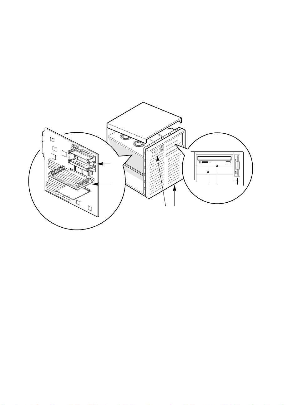
Two spring-loaded captive screws secure the removable metal door behind
the lower plastic front door to the chassis. This door provides proper
air-flow and easy access to the hot-docking bays for hot-swapping hard disk
drives in and out of the system. Both removable side covers are attached to
the chassis with three screws. They provide proper airflow and easy access
to the system board and power supplies. These covers can be secured to the
chassis with padlocks (not provided). Figures 1-1 and 1-2 show the major
system components.
1
1 Processor modules
2 Memory module
3 Front panel
4 SCSI hot-docking bays
5 5.25-inch external bays
6 CD-ROM drive
2
Figure 1-1. Server
5
6
7
43
OM05788A
M440LX Server System Product Guide
21
Page 22

9
8
7
6
Figure 1-2. Back/Right Side View
1 Left side cover
2 I/O panel
3 Knock-out slots for external SCSI connectors
4 Expansion slots
5 Power supplies
6 SCSI hot-docking bay
7 SCSI hot-docking backplane
8 5.25-inch peripheral bays
9 3.5-inch diskette drive
1
2
345
OM05792
22
Chapter 1 Server Description
Page 23

Controls and Indicators
Figure 1-3 shows the location of the system controls and indicators, external
peripheral bays, 3.5-inch diskette drive, and CD-ROM drive.
Front Panel:
• Green (HD ACT) LED: when lit, indicates hard drive activity.
• Yellow fan failure LED: when flashing, indicates the fan has failed.
• Yellow power supply failure LED: when flashing, indicates a power
supply has failed.
• 10 yellow hard drive failure LEDs: when lit, indicates a drive failure in
the hot-docking bay.
• Green power LED: when lit, indicates the presence of DC power in the
system. The LED goes out when the power is turned off or the power
source is disrupted.
• Power button: when pressed, turns the DC power on or off.
• Reset button: when pressed, resets the system and causes POST to run.
Peripherals:
• Diskette drive activity LED: when lit, indicates the drive is in use.
• Diskette drive ejector button: when pressed, ejects the disk.
• CD-ROM headphone jack: used to connect headphones or speakers.
• CD-ROM volume control: used to adjust the volume of headphones or
speakers.
• CD-ROM open/close button: used to open and close the CD tray.
• CD-ROM activity LED: when lit, indicates the drive is in use.
M440LX Server System Product Guide
23
Page 24
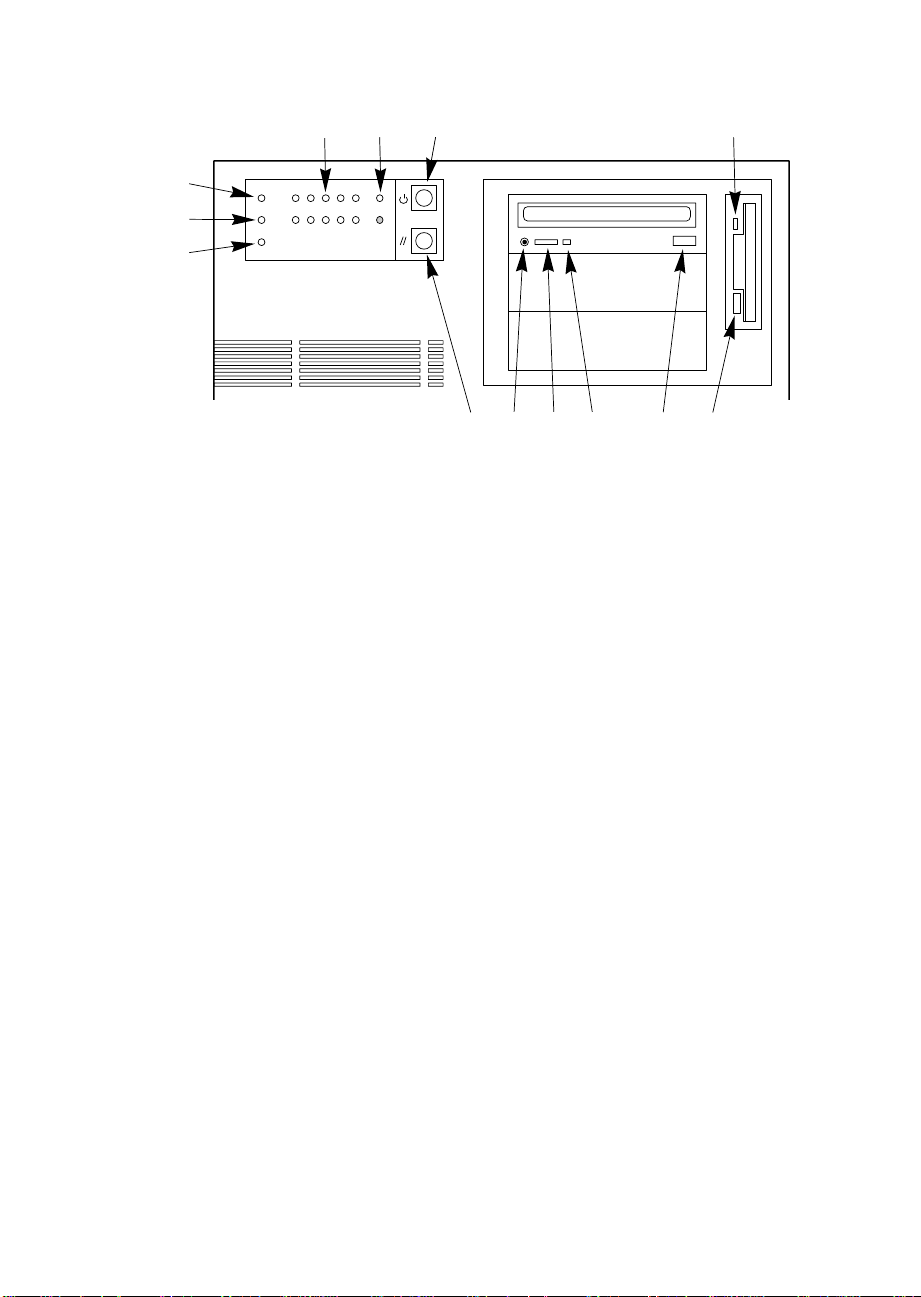
12 13
11
10
9
8
Figure 1-3. Controls and Indicators
1 Diskette drive activity LED
2 Diskette drive ejector button
3 CD-ROM open/close button
4 CD-ROM power LED
5 CD-ROM volume control
6 CD-ROM headphone jack
7 Reset button
8 Power supply failure LED
9 Fan failure LED
10 Hard drive activity LED
11 Drive failure LEDs for hot-docking bays
12 Power on LED
13 Power button
234567
1
OM05260
24
Chapter 1 Server Description
Page 25

System Security
There are several ways to prevent unauthorized entry or use of the system.
Security with padlocks and alarm switches:
• Secure the side covers and the hot-docking bay metal door to the chassis
by inserting padlocks (not provided) through the holes in the metal tabs
protruding through slots in the covers and door.
• Activate alarm switches for the side covers and hot-docking bay metal
door. These switches transmit alarm signals to the system board.
Software on the system board intercepts these signals and alerts the user
to unauthorized activity.
Security with the Setup utility:
• Set administrative and user passwords.
• Set secure mode to prevent keyboard or mouse input and to prevent use
of the front panel controls.
Security with the System Configuration Utility (SCU):
• Enable the keyboard lockout timer so that the system requires a
password to reactivate the keyboard and mouse after a specified
time-out period—1 to 128 minutes.
• Set an administrative password.
• Set a user password.
• Activate the secure mode hot-key.
• Disable writing to the diskette drive.
• Enable video blanking if using onboard video.
M440LX Server System Product Guide
25
Page 26
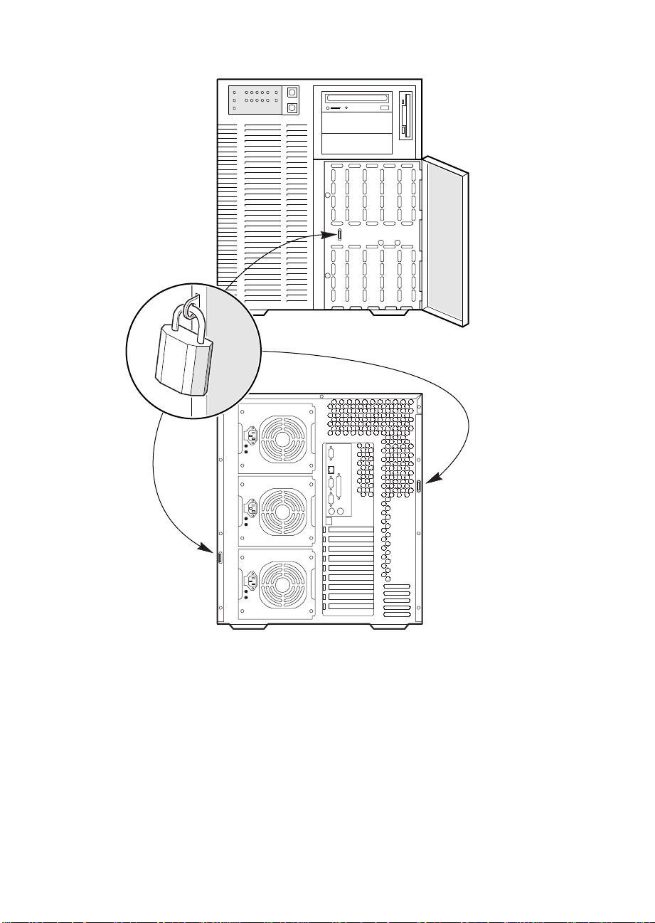
Figure 1-4. Security Padlocks
OM05793
26
Chapter 1 Server Description
Page 27

Password Protection
If you set the user password but not the administrative password, the BIOS
requires you to enter the user password before you can boot the system or
run the SCU. If you set both passwords, entering either one lets you boot
the system or enable the keyboard and mouse, but only the administrative
password lets you change the system configuration.
Secure Boot Mode
The secure boot mode allows the system to boot and run the operating
system (OS). However, you cannot use the keyboard or mouse until you
enter the user password.
You can use the SCU to put the system into the secure boot mode. If the
BIOS detects a CD in the CD-ROM drive or a diskette in drive A at boot
time, it prompts you for a password. When you enter the password, the
system boots from the CD-ROM drive or diskette drive and disables the
secure mode.
If there is no CD in the CD-ROM drive or diskette in drive A, the system
boots from drive C and automatically goes into secure mode. All enabled
secure mode features go into effect at boot time.
You can set a hot-key combination to secure the system immediately.
Boot Sequence Control
The BIOS security features determine the boot devices and the boot
sequence. They also control disabling writes to the diskette drive in secure
mode. You can use the SCU to select each boot device. The default boot
sequence is diskette, hard disk, CD-ROM, and Network.
Boot Without Keyboard
The system can boot with or without a keyboard. Before boot, the BIOS
displays a message whether it has detected a keyboard or not. During
POST, the BIOS automatically detects and tests the keyboard if it’s present.
Power and Reset Button Lock
If enabled by the Setup Utility, the power and reset buttons are disabled
when in the secure mode.
M440LX Server System Product Guide
27
Page 28

Diskette Write Protection
If the protection feature is enabled with the SCU, diskette writes are
disabled when the system is in the secure mode. Diskette write protection is
only in effect while the system is in the secure mode. Otherwise, write
protection is disabled.
Video Blanking
If enabled with the setup or SCU, the video screen goes blank when the
system is in secure mode.
Power System
The power system in the server may be configured with one, two, or three
360 watt power supplies.
The 360 watt power supply provides sufficient power for an entry level
server. The power supply accepts these input voltage ranges:
• 100-120 VAC at 50/60 Hertz (Hz); 7.7 A maximum current
• 200-240 VAC at 50/60 Hz; 4.4 A maximum current
If a single power supply fails in a redundant power system, the yellow
power supply failure LED on the front panel starts flashing. You can swap
out the faulty supply without shutting down the server.
Server Cooling
Two blowers inside the chassis provide cooling for the processors, memory
modules, and add-in boards. Two more fans may be installed for
redundant cooling. If a fan or blower fails, the server management
subsystem notifies the system board and turns on an LED on the front
panel.
A system with only one power supply includes an auxiliary fan to provide
cooling for the hard drives. A system with multiple power supplies
provides enough cooling without an auxiliary fan.
28
Chapter 1 Server Description
Page 29

Peripheral Drive Bays
3.5-inch User Accessible Diskette Drive Bay
The 3.5-inch diskette drive in the vertical 3.5-inch peripheral bay supports
720 KB and 1.44 MB media.
5.25-inch User Accessible Drive Bays
Three 5.25-inch half-height bays provide space for removable media devices
such as tape drives and CD-ROM drives. You can convert any two adjacent
5.25-inch bays to a single full-height bay. We recommend that you do not
use these bays for hard disk drives because they generate EMI, and ESD
susceptibility increases.
3.5-inch Hot-docking Drive Bays
Using industry standard 80-pin SCA connectors, the hot-docking backplane
in the upper bay supports up to five industry standard SCA hard disk
drives. The hot-docking bays accept peripherals that consume up to 11
watts of power and run at a maximum ambient temperature of 55 °C.
You can install an additional hot-docking backplane in the lower
hot-docking bay for five more drives. However, if you do, you must install
an additional power supply in the chassis to support drives in the lower
bay. The upper and lower hot-docking bays, when fully configured with 10
4 GB hard disk drives, provide over 40 GB of hard disk drive space.
The plastic front door on the front of the server covers a removable metal
door. Two spring-loaded captive screws secure the metal door to the
chassis. These doors provide proper air-flow and easy access to the drives
in the upper and lower hot-docking bays. Plastic drive carriers for 3.5-inch
wide by 1-inch high drives allow easy hot swapping of these drives without
shutting down the server.
With the RPX board installed on the system board, RAID software, and
SCSI hard disk drives in the hot-docking bays, you can easily set up RAID
applications.
M440LX Server System Product Guide
29
Page 30

Onboard RAID
With the RPX board installed on the system board, RAID software, and
SCSI hard disk drives in the hot-docking bays, you can easily set up RAID
applications. A two channel RAID solution can be constructed by installing
an RPX module with RAID firmware resident in the RPX FLASH memory.
The server system supports two types of embedded RAID firmware
packages: I2O compliant and vendor proprietary firmware. The RAID
features are as follows:
• RAID levels 0, 1, 3, 5, 0+1, and JBOD
• Support for hot spares, hot plugs, and user selectable rebuild rate
• Support for multiple rebuilds across separate arrays and multiple
consistency checks
• Write back cache support with battery backup
• Support for up to 2 terabytes per logical array and up to 64 terabytes of
attached disk storage
• Support for SAF-TE and SMART
Server System Board
ISA Expansion Slots
30
One of the ISA connectors shares a common chassis I/O expansion slot with
a PCI connector; you can use either ISA or PCI in the slot, but not both.
The ISA bus operates at up to 8.33 MHz and provides
• 24-bit memory addressing
• Type A transfers at 5.33 MB per second
• Type B transfers at 8 MB per second
• 8- or 16-bit data transfers
Chapter 1 Server Description
Page 31

PCI Expansion Slots
The seven PCI bus master slots on the system board provide for expansion
and performance enhancement. One of the PCI connectors shares a
common chassis I/O expansion slot with an ISA connector; you can use
either PCI or ISA in the slot, but not both.
The PCI bus operates at up to 33 MHz and provides
• 32-bit memory addressing
• Support for 5 V and 3.3V cards
• Burst transfers of up to 133 MB per second
• 8-, 16-, or 32-bit data transfers
• Plug and Play configuration
• Hierarchical bus to maximize connectivity
PCI Video Controller
The onboard Cirrus Logic CL-GD54M40 32-bit video graphics accelerator
contains a super video graphics array (SVGA) controller that is fully
compatible with these video standards: CGA
†
MDA
, and VGA. The standard server configuration comes with 512 KB of
onboard video memory allowing pixel resolutions of up to 1024 x 768 and
16 colors.
†
, EGA†, Hercules† Graphics,
The SVGA controller supports analog VGA monitors (single and multiple
frequency, interlaced and noninterlaced) with a maximum vertical retrace
interlaced frequency of 87 Hz.
The buffer size of the onboard video memory can be increased from 512 KB
to 1 MB with one 40-pin 256 K x 16, 60 ns fast-page dynamic random access
memory (DRAM). 1 MB of DRAM will allow the controller to support
132-column text modes and high resolution graphics with 1280 x 1024 x 16
colors. Depending on the environment, the controller displays up to 64,000
colors in some video resolutions. It also provides hardware accelerated bit
block transfers (BITBLT) of data.
M440LX Server System Product Guide
31
Page 32

Video Modes
The 54M40 provides all standard VGA modes. With 512 KB of video
memory, the standard server goes beyond standard VGA support. If
necessary, you can install an additional 512 KB of video memory on the
system board. The following tables show all supported video modes that
use 512 KB and 1 MB of video memory.
Table 1-1. Standard VGA Modes
Colors
Bits
(number/palette
Hexadecimal
Mode Number
0, 1 4 16/256K 360 X 400 14 31.5 70
2, 3 4 16/256K 720 X 400 28 31.5 70
4, 5 4 4/256K 320 X 200 12.5 31.5 70
6 4 2/256K 640 X 200 25 31.5 70
7 4 Mono 720 X 400 28 31.5 70
D 4 16/256K 320 X 200 12.5 31.5 70
E 4 16/256K 640 X 200 25 31.5 70
F 4 Mono 640 X 350 25 31.5 70
10 4 16/256K 640 X 350 25 31.5 70
11 4 2/256K 640 X 480 25 31.5 60
12 4 16/256K 640 X 480 25 31.5 60
12+ 4 16/256K 640 X 480 31.5 37.5 75
13 8 256/256K 320 X 200 12.5 31.5 70
Per
size) Resolution
Pixel
Pixel
Frequency
(MHz)
Horizontal
Frequency
(kHz)
Vertical
Frequency
(Hz)
32
Chapter 1 Server Description
Page 33

Table 1-2. Extended VGA Modes
Colors
Bits
(number/palette
Hexadecimal
Mode Number
14, 55 8 16/256K 1056 X 400 41.5 31.5 70
54 8 16/256K 1056 X 350 41.5 31.5 70
58, 6A 8 16/256K 800 X 600 40 37.8 60
58, 6A 8 16/256K 800 X 600 49.5 46.9 75
5C 8 256/256K 800 X 600 36 35.2 56
5C 8 256/256K 800 X 600 40 37.9 60
5C 8 256/256K 800 X 600 49.5 46.9 75
5D 8 16/256K
5D 8 16/256K 1024 X 768 65 48.3 60
5D 8 16/256K 1024 X 768 75 56 70
5D 8 16/256K 1024 X 768 78.7 60 75
5F 8 256/256K 640 X 480 25 31.5 60
5F 8 256/256K 640 X 480 31.5 37.5 75
60* 8 256/256K
60* 8 256/256K 1024 X 768 65 48.3 60
60* 8 256/256K 1024 X 768 75 56 70
60* 8 256/256K 1024 X 768 78.7 60 75
64* 16 64K 640 X 480 25 31.5 60
64* 16 64K 640 X 480 31.5 37.5 75
65* 16 64K 800 X 600 36 35.2 56
65* 16 64K 800 X 600 40 37.8 60
65* 16 64K 800 X 600 49.5 46.9 75
66* 16 32K Direct/256
66* 16 32K Direct/256
67* 16 32K Direct/256
67* 16 32K Direct/256
6C* 16 16/256K
* Requires 1 MB video memory.
Per
size) Resolution
Pixel
(interlaced)
(interlaced)
Mixed
Mixed
Mixed
Mixed
(interlaced)
1024 X 768 44.9 35.5 87
1024 X 768 44.9 35.5 87
640 X 480 25 31.5 60
640 X 480 31.5 37.5 75
800 X 600 40 37.8 60
800 X 600 49.5 46.9 75
1280 X 1024 75 48 87
Pixel
Frequency
(MHz)
Horizontal
Frequency
(kHz)
Vertical
Frequency
(Hz)
M440LX Server System Product Guide
33
Page 34

SCSI Controllers
The system board includes two wide/fast-20 SCSI controller chips
integrated as PCI bus masters. These controllers support:
• An 8-bit (narrow SCSI) data path at a data transfer rate of 20 MB/sec.
• A 16-bit (wide SCSI) data path at a data transfer rate of 40 MB/sec.
• Data transfer rates of 133 MB/sec as PCI bus masters.
• The connection of a maximum of seven 8-bit narrow SCSI devices to
each controller.
• The connection of a mixture of up to fifteen 16-bit wide and/or 8-bit
narrow SCSI devices to each controller (maximum of seven 8-bit narrow
devices).
The system board also includes a narrow SCSI controller integrated as a PCI
bus master. You can connect a maximum of seven narrow SCSI devices to
this controller.
The SCSI controllers provide active negation outputs, controls for external
differential transceivers, and a disk activity output. Active negation outputs
reduce the chance of data errors by actively driving both polarities of the
SCSI bus and avoiding indeterminate voltage levels and common-mode
noise on long cable runs. The SCSI output drivers can directly drive a
48 milliampere (mA), single-ended SCSI bus with no additional drivers.
IDE Controller
The PIIX4 multifunction device on the system board acts as a PCI-based Fast
IDE controller that supports
• PIO and IDE DMA/bus master operations
• Mode 4 timings
• Transfer rates up to 32 MB/sec
• Buffering for PCI/IDE burst transfers
• Master/slave IDE mode
34
Chapter 1 Server Description
Page 35

Server Management
During normal operation, server management receives information about
server status and monitors power supply voltages and operating
temperature. If server management software determines that the server is
not operating within specified limits, the software attempts to notify a
supervisor or an administrator of the server’s condition. Server
management features are implemented with the following system board
microcontrollers.
Baseboard Management Controller (BMC)
does the following:
• Monitors the processor power supply voltage levels
• Monitors then processor thermal trip and internal error signals
• Monitors the fan sensors
• Manages two I
2
C thermal sensors located near each processor
• Manages fault resilient booting (FRB) that controls the ability to boot the
server using either processor in the event of a catastrophic processor
failure
Front Panel Processor (FPP)
on the system board does the following:
• Manages power, reset, and front panel NMI buttons
• Monitors all power control sources on the front panel, server manager
module, PIIX4, and RTC power control signals
An EEROM associated with the system board temperature sensor contains
the following:
• Chassis ID
• System board ID
• Power state
• System board temperature
• Intrusion detection during both power on and off conditions
M440LX Server System Product Guide
35
Page 36

Pentium II Processor
The system board has two connectors for Pentium II processors. The
secondary processor requires a plug-in DC to DC converter on the system
board to provide power to the processor.
In a symmetric multiprocessor (SMP) environment, all processors are equal
and have no preassigned tasks. Distributing the processing loads between
both processors increases system performance. This is particularly useful
when application demand is low and the I/O request load is high. In an
SMP environment, both processors share a common bus, the same interrupt
structure, and access to common memory and I/O channels. The SMP
implementation conforms to the Multiprocessor Specification Version 1.4.
Memory Module
The memory module has eight DIMM sockets. The module supports from
16 MB to 1 GB of extended data out (EDO) ECC memory 3.3 V 60 ns
DRAMs, mounted on JEDEC DIMMs. You may install mixed sizes and
types of DRAM DIMMS in the eight memory banks; however, their speeds
must be the same. The BIOS automatically detects and initializes the
memory array.
ECC memory detects and corrects single-bit errors from DRAM in real time,
allowing your system to function normally. It detects all double-bit errors
but does not correct them; it also detects all three-bit and four-bit adjacent
errors in a DRAM nibble but does not correct them. When one of these
multiple-bit errors occurs, the PAC generates an SERR (system error) that
usually halts the system. ECC is calculated on a 64 bit wide memory basis.
36
Chapter 1 Server Description
Page 37

System Configuration Options
Base System Configuration
• System board assembly
• Base system chassis
The electro-galvanized metal chassis minimizes electromagnetic
interference (EMI) and radio frequency interference (RFI). It contains:
Three power supply bays with one 360 watt power supply installed
One vertical drive bay that contains a diskette drive
Three standard 5.25-inch drive bays (a CD-ROM drive is installed in
the top bay)
Two bays each with space for five 3.5-inch SCSI hard disk drives (a
SCSI backplane is installed in the top bay)
Nine I/O expansion slot covers
Two blowers for cooling the processor modules
Two cooling fans
One control panel
• Uni Processor Kit
Choice of 266MHz or 300MHz processor
Heat sink assembly
Dual processor retention mechanism
• Processor termination card
• Memory Module (either an EDO or SDRAM module)
M440LX Server System Product Guide
37
Page 38

System Upgrade Options
The system upgrade options provide enhancement to the capabilities of the
base system. These options do not include memory and peripheral
upgrades.
• Dual Processor upgrade:
Upgrade from a single processor system to dual processor system. You
must use processors running at the same frequency. This upgrade kit
comes with heat sink assembled processor and VRM. Choose between a
266 MHz or 300 MHz processor.
• Power supply upgrade:
The system can contain three power supplies. A second power supply
provides additional power or acts as an redundant power supply,
depending on the system configuration. The powershare upgrade kit is
not required to upgrade from two power supplies to three power
supplies.
360 W power supply
Powershare upgrade kit
• SCSI backplane upgrade:
The SCSI backplane upgrade allows you to use up to 10 hot-swap
drives.
38
• Rack adapter kit:
The chassis can be mounted into rack with the rack adapter kit.
• Embedded RAID (RPX board):
This upgrade provides low cost I2O or non-I2O RAID. This RAID
solution uses the on board dual ultra SCSI channels. The kit includes an
RPX board and the required RAID software. SIMMs for the RPX board
are not included.
■
■
■
■
■
■
Chapter 1 Server Description
Page 39

Installing The System
This chapter tells how to
• Select a site
• Install the Pentium II processor
• Install the memory module
• Set the line voltage selector switch and check the power cord(s)
• Connect input and output devices
• Turn on the server and create installation diskettes from the
Configuration Software CD
• Run PC Diagnostics (Testview)
• Exit to DOS
2
M440LX Server System Product Guide
39
Page 40

Selecting a Site
The server operates reliably within the specified environmental limits (see
page 41). Choose a site that is
• near a grounded, three-pronged power outlet
a. In the United States and Canada, this means a NEMA 5-15R outlet
for 100-120 VAC or a NEMA 6-15R outlet for 200-240 VAC.
b. For international sites, this means a three-pronged power outlet
applicable for the electrical code of the region.
CAUTION
!
▲
▲
Ensure that the power service connection is through a
properly grounded outlet.
• clean and dust-free
• well ventilated and away from sources of heat
• spacious enough to provide sufficient room behind and around the
server so that you can remove AC power from it by unplugging the
power cord from each power supply or wall outlet
40
✏
• isolated from strong electromagnetic fields and electrical noise caused
• away from sources of vibration or physical shock
Note
For cooling, airflow, and access to the server, allow about
31 centimeters (12.2 inches) of clearance in back,
60 centimeters (23.6 inches) on each side, and 22 centimeters
(9 inches) in front.
by electrical devices—such as air conditioners, large fans, large electric
motors, radio and TV transmitters, and high frequency security devices
Chapter 2 Installing The System
Page 41

Physical Specifications
Height 51.44 cm (20.25 inches)
Width 43.56 cm (17.15 inches)
Depth 51.13 cm (20.13 inches)
Weight 29 kg (63 lbs.) minimum configuration
44 kg (97 lbs.) maximum configuration
Environmental Specifications
Temperature
Nonoperating
Operating
Humidity
Operating wet bulb
Nonoperating
Operating
Shock
Nonoperating
Operating
–40° to 70 °C (–40° to 158 °F)
5° to 35 °C (41° to 95 °F); derated 0.5 °C for every
1000 ft (305 m)
Not to exceed 33 °C (91.4 °F) (with diskette drive or
hard disk drive)
95% relative humidity (noncondensing) at 55 °C (131 °F)
85% relative humidity (noncondensing) at 35 °C (95 °F)
20 g, 11 msec, 1/2 sine
2.0 g, 11 msec, 1/2 sine
Altitude
Nonoperating
Operating
Acoustic noise Typically <45 dBA at 18° to 24 °C (65° to 75 °F) with five
Electrostatic
discharge (ESD)
AC Input Power
115 VAC
230 VAC
M440LX Server System Product Guide
To 50,000 ft (15,240 m)
To 10,000 ft (3,048 m)
internal hard disk drives (measured at 1 meter from the
system with the peripherals idle). The noise of the
variable-speed system fan will increase with
temperature and power load. Your selection of
peripherals may change the noise level.
Tested to 20 kilovolts (kV), no component damage.
(CD-ROM drive tested to 15 kV, manufacturer’s
specification.)
Single power supply, fully loaded
100 to 120 VAC, 7.7 A, 50/60 Hz
200 to 240 VAC, 4.4 A, 50/60 Hz
41
Page 42

After Unpacking the Server
Inspect the shipping box for evidence of mishandling during transit. If the
shipping box is damaged, photograph it for reference. After removing the
contents, keep the damaged box and the packing materials. If the contents
appear damaged, file a damage claim with the carrier immediately.
!
▲
Save the shipping boxes and packing materials to repackage the server in
the event you decide to move it to another site.
WARNING
The minimum server configuration weighs 29 kg (63 lbs.)
and the maximum one weighs 44 kg (97 lbs.). To avoid
personal injury, have someone help you move the server.
Installing the Pentium II Processor
The server is shipped without the processor module installed on the system
board. Turn to Chapter 4, “Working Inside Your System,” and follow the
instructions for installing the processor module. Before you install the
module in your server, observe the warnings and cautions provided for
your safety on page 3, “Safety Guidelines.”
Installing the Memory Module
42
The server is shipped without the memory module installed on the system
board. Turn to Chapter 4, “Working Inside Your System,” and follow the
instructions for installing the memory module. Before you install the
module in your server, observe the warnings and cautions provided for
your safety on page 3, “Safety Guidelines.”
Chapter 2 Installing The System
Page 43

Connecting Peripheral Devices
If your system normally operates without a monitor or keyboard—for
example, as a network server—you must install them to configure the
system. You may remove them after running the SCU. For information
about running this utility, see Chapter 3, “Configuring The System,”.
Connect your keyboard, mouse, monitor, and other peripheral devices after
installing all internal options and replacing the side cover. See Figure 2-1.
Warnings and Cautions
Before connecting peripheral devices to the server, observe the warnings
and cautions provided for your safety on page 3, “Safety Guidelines.”
Server integration should be done by a qualified technical person.
Keyboard
Insert the cable connector of a PS/2-compatible keyboard into the 6-pin
miniature Deutsche Industrie Norm (DIN) connector on the system back
panel. The keyboard port is overcurrent-protected by a 1-ampere positive
temperature coefficient (PTC) resistor.
Mouse
Insert the cable connector of a PS/2-compatible mouse into the 6-pin
miniature DIN connector on the system back panel. The mouse port is
overcurrent-protected by a 1-ampere PTC resistor.
Monitor
Insert the cable connector of the video monitor into the 15-pin connector of
the Super VGA port on the system back panel.
Other Devices
Connect other external peripheral devices—for example, a printer and an
external modem—by following the instructions in the documentation
included with the device. Besides the keyboard, mouse, and monitor ports,
the back panel also provides two serial ports, and a parallel port.
M440LX Server System Product Guide
43
Page 44
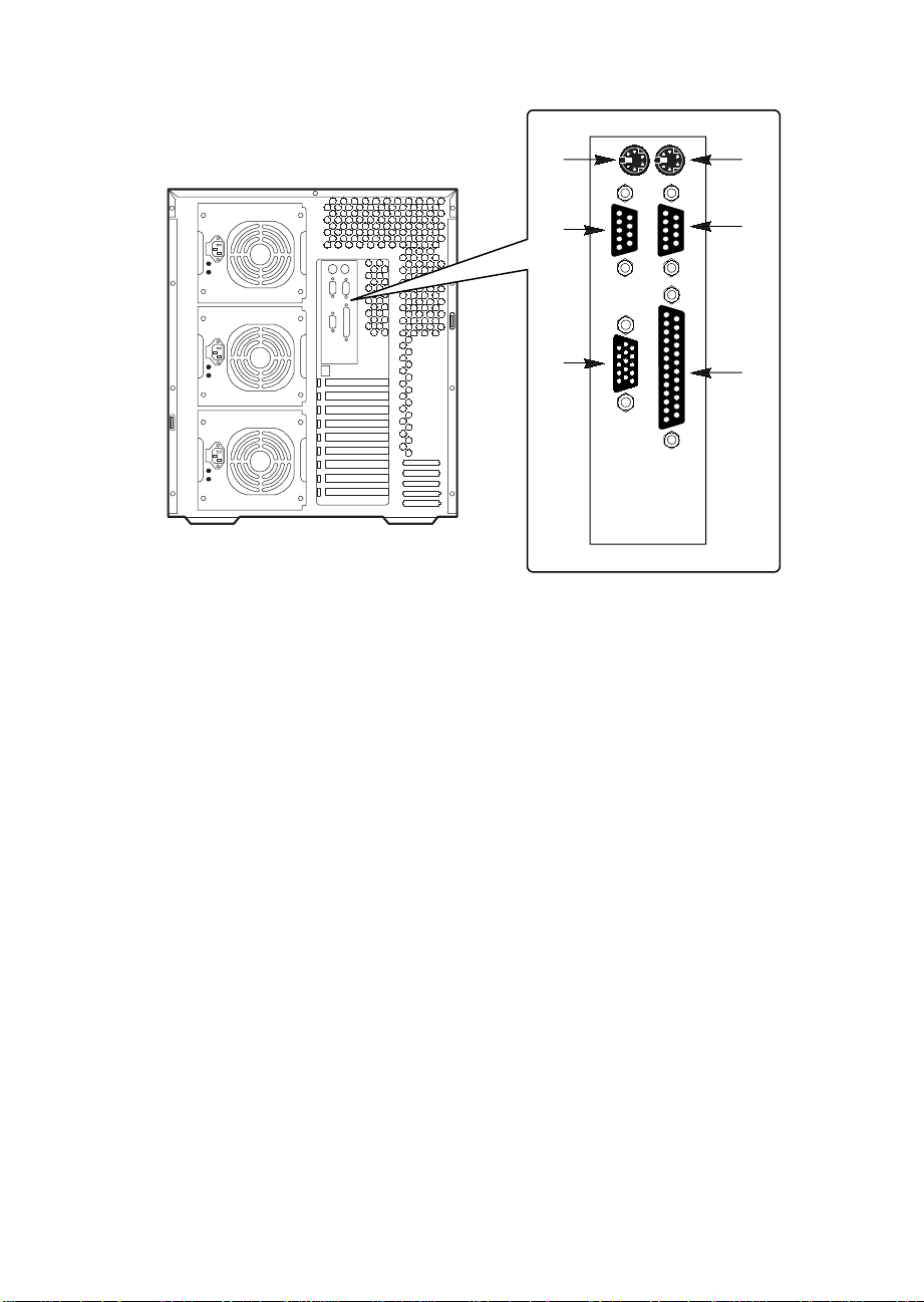
1
2
6
5
Figure 2-1. Server I/O Panel
1. PS/2-compatible keyboard connector
2. PS/2-compatible mouse connector
3. PS/2-compatible serial port 1 (COM1) connector
4. PS/2-compatible parallel port (LPT1) connector
5. Super VGA connector
6. PS/2-compatible serial port 2 (COM2) connector
3
4
OM05779A
44
Chapter 2 Installing The System
Page 45

Checking the Power Cord(s)
!
▲
If a power cord supplied with the system is not compatible with the AC
wall outlet in your region, get one that meets the following criteria:
• The cord must be rated for the available AC voltage and have a current
• The connector that plugs into the wall outlet must be a grounding-type
• The connector that plugs into the AC receptacle on the system power
• In Europe, the cord must be less than 4.5 meters (14.76 feet) long, and it
WARNING
Do not attempt to modify or use a supplied AC power
cord if it is not the exact type required.
rating that is at least 125% of the current rating of the system.
male plug designed for use in your region. It must have certification
marks showing certification by an agency acceptable in your region.
supply must be an IEC 320, sheet C13, type female connector.
must be flexible <HAR> (harmonized) or VDE certified cordage to
comply with the system's safety certifications.
Turning on Your Server
!
▲
WARNINGS
Ensure that the line voltage selector switch on each power
supply is set to the correct line source voltage (see
page 42). If the setting is incorrect, the power supply will
be damaged when you plug the power cord into an AC
outlet.
The
power button
turn off the AC power. To remove AC power from the
server, you must unplug the AC power cord from each
power supply or wall outlet.
1. Make sure all external devices, such as a monitor, keyboard, and mouse
(optional) have been connected.
2. Remove drive protection cards (if present) from the diskette and tape
drives.
3. Turn on your video monitor.
M440LX Server System Product Guide
on the front panel of the server
does not
45
Page 46

4. Plug the female end of each AC power cord into each input receptacle
on the back of the chassis (your server may be configured with one, two,
or three power supplies).
5. Plug the male end of the cord into a grounded, three-pronged power
outlet. (Repeat for each power supply in the server.)
6. If the server doesn’t come on when you plug it into the AC outlet, press
the power button (Figure 2-2).
7. Verify that the power-on light on the front panel is lit. After a few
seconds POST begins. See “Power-on Self-Test.”
3
1
2
OM05780
Figure 2-2. Power and Reset Buttons
1. Power button
2. Reset button
3. Power-on light (LED)
Power-on Self-Test
Each time you turn on the server, the power LED on the front panel turns
on and the power-on self-test (POST) starts running. It checks the system
board, processor, memory, keyboard, and most installed peripheral devices.
During the memory test, the POST displays the amount of memory that it is
able to access and test. Depending on the amount of memory installed on
the memory module, it may take several minutes to complete the memory
test.
46
Chapter 2 Installing The System
Page 47

Creating Installation Software Diskettes
1. Insert the Configuration Software CD in the CD-ROM Drive.
2. Reboot the system.
3. When POST completes, the server boots from the CD and displays the
CD-ROM menu.
4. Follow the menu prompts to create the server configuration software
diskettes.
■
■
■
■
■
■
M440LX Server System Product Guide
47
Page 48

48
Chapter 2 Installing The System
Page 49

Configuring The System
This chapter tells how to run the configuration utilities and install video
drivers.
Configuration Utilities
Symbios SCSI Utility
•
host adapters and devices in the system. See page 76.
System Configuration Utility (SCU)
•
CD shipped with the system. See Chapter 2, “Installing The System,”
for instructions on creating an SCU diskette. See page 51.
BIOS Setup Utility
•
backed memory of the real-time clock (RTC) on the system board. See
page 59.
If the diskette drive is disabled or improperly configured, use Setup to
enable it so that you can run the SCU. If necessary, disable the drive after
exiting the SCU. Information entered using the SCU overrides any entered
using Setup.
is stored in both flash memory and the battery-
3
is used to configure/view the settings of the SCSI
is on the Configuration Software
M440LX Server System Product Guide
49
Page 50

Power-on Self-Test
!
▲
Turn on the video monitor and system. After a few seconds the power-on
self test (POST) begins.
Each time you turn on the system the power LED on the front panel turns
on and the POST starts running. The POST checks the system board,
processor, memory, keyboard, and most installed peripheral devices.
During the memory test, the POST displays the amount of memory that it is
able to access and test. Depending on the amount installed on the memory
module, the test may take several minutes to complete.
These screen prompts and messages appear after the memory test:
Press F2 key if you want to run SETUP
If you do not press <F2>, the boot process continues, and this message
appears:
Press Ctrl C to start configuration Utility!
If you have installed SCSI devices in the system, press <Ctrl+C>. When the
utility appears, follow the instructions on the monitor to configure the
onboard SCSI host adapter settings and run the SCSI disk utilities. See
“Using the Symbios SCSI Utility” on page 76.
WARNING
The power button on the front panel of the system does
not turn off the AC power. To remove AC power from the
system, you must unplug the AC power cord from each
power supply or wall outlet.
50
Chapter 3 Configuring The System
Page 51

When to Use the System Configuration Utility
The SCU lets you do the following:
• Add and remove boards
• Change the system configuration settings
• Save the system configuration
• View switch and jumper settings on the boards in the system
To install or remove an ISA add-in board in the system, you must run the
SCU to reconfigure the system. Running the SCU is optional for a PCI
add-in board.
The SCU is PCI-aware and complies with the ISA Plug and Play
specifications. The SCU works with any compliant configuration (.CFG) or
overlay (.OVL) files supplied by peripheral device manufacturer.
The system board comes with .CFG and .OVL files. The .CFG file describes
the board’s characteristics and the system resources that the board requires.
The configuration registers on PCI and ISA Plug and Play add-in boards
contain the same type of information that is in a .CFG file. However, some
ISA add-in boards do come with a .CFG file.
The SCU uses the information provided by the .OVL and .CFG files,
configuration registers, NVRAM, and the information that you enter, to
specify a system configuration. It configures the system by writing the
configuration information to flash memory.
The SCU stores most of the configuration values in the battery-maintained
memory (NVRAM) of the real-time clock (RTC), and it stores the rest of the
values in flash memory. These values take effect when you boot the system.
The POST checks the values against the actual hardware configuration; if
they do not agree, it generates an error message. You must then run the
SCU to specify the correct configuration before the system boots.
The SCU always updates a checksum for both areas so that the BIOS can
detect any potential data corruption before the actual hardware
configuration takes place. If the data is corrupted, the BIOS requests that
the user configure the system before it can boot.
Pressing <F1> on the keyboard, in response to the BIOS prompt during the
POST, activates the BIOS Setup Utility.
M440LX Server System Product Guide
51
Page 52

How to start the SCU
Before you can run the SCU from a diskette, you must copy the SCU from
the Configuration Software CD to a DOS bootable diskette. For instructions
on creating an SCU diskette, see Chapter 2, “Installing The System.”
1. Turn on the video display monitor and system.
2. There are three ways to start the SCU.
• After creating an SCU diskette from the CD: Insert the
System Configuration Utility Disk in drive A, and press the
reset push-button switch or <Ctrl+Alt+Del> to reboot the
system from the diskette.
• After installing the operating system: Insert the System
Configuration Utility Disk in drive A, and copy it to a
directory on the hard drive. While in the directory, type
AMISCU
• From diskette after installing the operating system: Insert
the System Configuration Utility Disk in drive A. At the
MS-DOS
drive A. Type
When you see this message:
MS-DOS Startup Menu
-------------------------------
and press <Enter>.
†
prompt, type a: and press <Enter> to change to
AMISCU
and press <Enter> to start the SCU.
52
1. Execute AMISCU
2. Execute AMISCU for system with PNP OS
If the operating system in the system supports Plug and Play add-in
boards, press <2> to start the SCU. If not, press <1> to start it.
3. When the SCU title appears on the screen, press <Enter> to continue.
↑
4. From the main menu, press <
> or <↓> to highlight an item and then
press <Enter> to select it. If you are using a mouse, point to an item and
double-click the left button to select it. Press <F1> at any time for help
about a selection.
5. For information about setting up the system select “Step 1: About
System Configuration” from the main menu.
Chapter 3 Configuring The System
Page 53

System Board Settings Field Descriptions
Default values are in bold typeface.
Systems Group
System Identification and Version Information
Config and Overlay Version Displays configuration and overlay version.
BIOS Version String Displays BIOS version.
MP Spec. Version
MP Spec V1.1
MP Spec V1.4
System Processor Modules
Processor 1 Pentium II Processor at XXXMHz (Display only).
Processor 2 Pentium II Processor at XXXMHz (Display only).
Memory Subsystem Group
Shadowing ISA ROMs Options
Shadowing ISA ROM at C8000 Enable
Disable
Shadowing ISA ROM at CC000 Enable
Disable
Shadowing ISA ROM at D0000 Enable
Disable
Shadowing ISA ROM at D4000 Enable
Disable
Shadowing ISA ROM at D8000 Enable
Disable
Shadowing ISA ROM at DC000 Enable
Disable
M440LX Server System Product Guide
53
Page 54

Extended Memory Options
Cache Mode Disable
Enable
Memory Gap Control
Disable
Extended
On-Board Disk Controllers
On-Board Floppy Controller
On-Board IDE Controller
Enable - Primary
Enable - Secondary
Disable
Enable
Disable
Onboard Communications Devices
Serial Port 1 Configuration Port 1 Disable
3E8h - IRQ 4
3E8h - IRQ 3
3F8h - IRQ 4
3F8h - IRQ 3
2E8h - IRQ 4
2E8h - IRQ 3
2F8h - IRQ 4
2F8h - IRQ 3
Serial Port 2 Configuration Port 2 Disable
3E8h - IRQ 4
3E8h - IRQ 3
3F8h - IRQ 4
3F8h - IRQ 3
2E8h - IRQ 4
2E8h - IRQ 3
2F8h - IRQ 4
2F8h - IRQ 3
Serial Port 2 Mode
54
Port 2 Normal Mode
Port 2 IrDA
Port 2 ASK-IR Mode
†
Mode
Chapter 3 Configuring The System
Page 55

Parallel Port Configuration Parallel Port Disable
378h - IRQ 7
278h - IRQ 7
3BCh - IRQ 7
378h - IRQ 5
278h - IRQ 5
3BCh - IRQ 5
Parallel Port Mode Output Only Parallel Port
Bi-directional Parallel Port
Enhanced Parallel Printer Port
Extended Capabilities Parallel Port, DMA 1
Extended Capabilities Parallel Port, DMA 3
Floppy Drive Subsystems Group
Floppy drive A Options
3.5-inch 1.44/1.25 MB drive
5.25-inch 360 KB drive
5.25-inch 1.2 MB drive
3.5-inch 720 KB drive
3.5-inch 2.88 MB drive
Disable or Not Installed
Floppy drive B Options
Disable or Not Installed
5.25-inch 1.2 MB drive
5.25-inch 360 KB drive
3.5-inch 2.88 MB drive
3.5-inch 1.44/1.25 MB drive
3.5-inch 720 KB drive
IDE Subsystem Group
IDE Configuration – Primary Master
Configuration Selection None
User
Auto
CD
M440LX Server System Product Guide
55
Page 56

IDE Drive Options – Primary Master
If the Configuration Selection Field is set to Auto, the following fields can
not be modified.
Multi-Sector Transfer 2 Sector/Block
4 Sector/Block
8 Sector/Block
16 Sector/Block
Disable
Translation Mode
Transfer Mode
Standard CHS
Logical Block Addressing
Standard
PIO 1
PIO 2
PIO 3
PIO 4
IDE Configuration – Primary Slave
Configuration Selection None
User
Auto
CD
IDE Drive Options – Primary Slave
If the Configuration Selection Field is set to Auto, the following fields can
not be modified.
Multi-Sector Transfer 2 Sector/Block
4 Sector/Block
8 Sector/Block
16 Sector/Block
Disable
Translation Mode
Standard CHS
Logical Block Addressing
Transfer Mode
56
Standard
PIO 1
PIO 2
PIO 3
PIO 4
Chapter 3 Configuring The System
Page 57

Multiboot Group
Boot Device Priority
IPL Devices Diskette Drive
Hard Drive
Removable media
Any I2O drives
ATAPI CD-ROM Drive
Diagnostic Boot
BCV Devices IDE drives
Other Bootable Device
KB and Mouse Subsystem Group
Typematic Speed
Typematic Delay 250 mS Delay
30 CPS
26 CPS
21 CPS
18 CPS
13 CPS
10 CPS
6 CPS
2 CPS
500 mS Delay
750 mS Delay
1000 mSec Delay
Mouse Control Option
Mouse Enabled
Mouse Disabled
Console Redirection
COM Port for Redirection
Serial Port Baud Rate
M440LX Server System Product Guide
Enable Redirection on Port 3F8h IRQ4
Enable Redirection on Port 2F8h IRQ3
Enable Redirection on Port 3E8h IRQ3
Disable
9600 Baud
19.2K Baud
38.4K Baud
115.2K Baud
57
Page 58

Hardware Flow Control
None
CTS/RTS
Xoff/Xon
CTS/RTS + CD
Select Terminal Type
PC-ANSI
VT100
Security Subsystem
Administrative Password Option
Password Menu Enter Password XXXXX
Verify Password XXXXX
User Password Option
Password Menu Enter Password XXXXX
Verify Password XXXXX
Other Security Subsystem Options
Hot Key Option
Lockout Timer
Disable
Enable
Disable
1 Minute
2 Minute
5 Minute
10 Minute
20 Minute
1 Hour
2 Hour
Secure Boot Mode
Video Blanking
Floppy Writes
58
Disable
Enable
Disable
Enable
Disable
Enable
Chapter 3 Configuring The System
Page 59

SCSI ROM BIOS Options Group
Embedded SCSI Option ROM
Scan
Enable
Disable
Management Subsystem Group
System Management Mode
Event Logging Disable
Disable
Enable
Enable
M440LX Server System Product Guide
59
Page 60

When to Run the BIOS Setup Utility
The Setup utility lets you change the system configuration defaults. It does
not let you enter or change information about PCI or ISA add-in boards; you
must use the SCU instead. Setup stores most of the configuration values in
the battery-backed memory of the RTC; the rest of the values are stored in
flash memory. The values take effect when you boot the system. The POST
checks these values against the actual hardware configuration; if they do not
agree, it generates an error message. You must then run Setup to specify
the correct configuration.
You can run the Setup utility with or without an operating system being
present.
Since values entered using the Setup utility are overwritten when you run
the SCU, you should only run Setup under the following conditions:
• To enable the diskette drive
• If you do not have access to a diskette drive
• If you do no want to configure any ISA add-in boards in the system
Running the Setup Utility
Reset the system. When you see this message:
Press F2 key if you want to run SETUP
60
Press <F2> to run Setup.
Setup provides six major menus and nine submenus:
• Main Menu
Primary IDE Master Submenu
Primary IDE Slave Submenu
Keyboard Features Submenu
• Advanced Menu
PCI Configuration Submenu
Integrated Peripheral Configuration Submenu
• Security Menu
Chapter 3 Configuring The System
Page 61

• Server Menu
System Management Submenu
Console Redirection Submenu
• Boot Menu
Boot Device Priority Submenu
Hard Drive Submenu
• Exit Menu
Use the following keys to navigate through the menus and submenus.
Press To
F1 Get help about an item
ESC Go back to a previous item
Enter Select an item
↑
↓
← →
F5 Load Setup defaults
F6 Return to previous values
F10 Save and exit Setup
Return to a previous item
Move to the next Item
Select a major menu
M440LX Server System Product Guide
61
Page 62

Main Menu
Default values are in bold typeface, and autoconfigured values are shaded.
Feature Option Comments
System Time Current Time To change this field type the hour (this
is a 24-hour clock), minutes, and
seconds, each followed by <Enter>.
System Date Current Date To change this field type the month,
day, and year, each followed by
<Enter>.
Diskette A: Disabled
360 KB 5¼”
1.2 MB 5¼”
720 KB 3½”
1.44/1.25 MB 3½”
2.88 MB 3½”
Diskette B:
Primary IDE Master Press <Enter> See page 63, IDE Submenu.
Primary IDE Slave Press <Enter> See page 63, IDE Submenu.
Keyboard Features Press <Enter> See page 64, Keyboard Features
Memory Cache
CPU Speed Setting 133 MHz
Language
Disabled
360 KB 5¼”
1.2 MB 5¼”
720 KB 3½”
1.44/1.25 MB 3½”
2.88 MB 3½”
Enabled
Disabled
233 MHz
266 MHz
300 MHz
333 MHz
English (US)
German
French
Italian
Spanish
Submenu.
To activate this field, see Chapter 8,
“System Board Jumpers”.
62
Chapter 3 Configuring The System
Page 63

IDE Submenu
Feature Option Comments
Type
Multi-Sector
Transfers
LBA Mode Control
32 Bit I/O
Transfer Mode
Cylinders 0
Heads 0
Sectors/Track 0
Auto
None
CD-ROM
User
Disabled
2 Sectors
4 Sectors
8 Sectors
16 Sectors
Disabled
Enabled
Disabled
Enabled
Standard
Fast PIO 1
Fast PIO2
Fast PIO3
Fast PIO4
Use the <+> and <-> keys to cycle
through the choices. Depending on
the selection, some of the following
fields will be visible.
Determines the number of sectors per
block for multiple sector transfers.
Disables/Enables Logical Block
Access.
Disables/Enables 32-bit IDE data
transfers.
Selects the method for moving data
to/from the drive.
Maximum Capacity X MB The system calculates this number
from the cylinders, heads, and
sectors/track numbers.
M440LX Server System Product Guide
63
Page 64

Keyboard Features Submenu
Feature Option Comments
Numlock
Key Click
Keyboard auto-repeat
rate
Keyboard auto-repeat
delay
Auto
On
Off
Disabled
Enabled
30/sec
26.7/sec
21.8/sec
18.5/sec
13.3/sec
10/sec
6/sec
2/sec
1/4 sec
1/2 sec
3/4 sec
1 sec
Selects the state for NumLock at
power on.
64
Chapter 3 Configuring The System
Page 65

Advanced Menu
Feature Option Comments
Plug & Play OS
Reset Configuration
DataNoYes
PCI Configuration Press <Enter> See page 66, PCI configuration
Integrated Peripheral
Configuration
Use Multiprocessor
Specification
Large Disk Access
Mode
Enable Memory Gap
Delay on Option
ROMS
Clock control
No
Yes
Press <Enter> See page 68, Integrated Peripheral
1.1
1.4
DOS
Other
Disabled
Extended
Disabled
Enabled
Enabled
Disabled
Select Yes if you are booting a Plug
and Play capable operating system.
Select Yes if you want to clear the
System Configuration Data during the
next boot. Automatically reset to No
during boot.
Submenu.
Configuration Submenu.
DOS - select DOS
†
, Novell† NetWare†, or other OS
UNIX
- select Other.
Enabled programs the clock drivers to
optimum settings
IO processor
M440LX Server System Product Guide
Enabled
Disabled
Enables onboard IO processor
(i960 RD)
65
Page 66

PCI Configuration Submenu
Feature Option Comments
PCI Device,
Embedded SCSI
Devices
PCI Device, Slot #1 Press <Enter> See page 68, PCI Device Submenu
PCI Device, Slot #2 Press <Enter> See page 68, PCI Device Submenu
PCI Device, Slot #3 Press <Enter> See page 68, PCI Device Submenu
PCI Device, Slot #4 Press <Enter> See page 68, PCI Device Submenu
PCI Device, Slot #5 Press <Enter> See page 68, PCI Device Submenu
PCI Device, Slot #6 Press <Enter> See page 68, PCI Device Submenu
PCI Device, Slot #7 Press <Enter> See page 68, PCI Device Submenu
Press <Enter> See page 67, Embedded SCSI Device
Submenu
66
Chapter 3 Configuring The System
Page 67

Embedded SCSI Device Submenu
Feature Option Comments
Option ROM Scan
Narrow SCSI Latency
Timer
Wide SCSI A Latency
Timer
Wide SCSI B Latency
Timer
Enabled
Disabled
Default
0020h
0040h
0060h
0080h
00A0h
00C0h
00E0h
Default
0020h
0040h
0060h
0080h
00A0h
00C0h
00E0h
Default
0020h
0040h
0060h
0080h
00A0h
00C0h
00E0h
M440LX Server System Product Guide
67
Page 68

PCI Device Submenu
Feature Option Comments
Option ROM Scan
Enable Master Disabled
Wide SCSI A Latency
Timer
Enabled
Disabled
Enabled
Default
0020h
0040h
0060h
0080h
00A0h
00C0h
00E0h
Integrated Peripherals Submenu
Feature Option Comments
Serial port A Disabled
Enabled
Auto
PnP OS
Serial port A: Base
I/O address
3F8
2F8
3E8
2E8
Serial port A:
Serial port B Disabled
Serial port B: Mode
68
Interrupt
IRQ 3
IRQ 4
Enabled
Auto
PnP OS
Normal
IrDA
ASK-IR
continued
Chapter 3 Configuring The System
Page 69

Integrated Peripherals Submenu
Feature Option Comments
(continued)
Serial port B: Base
I/O address
Serial port B:
Interrupt
Parallel port Disabled
Parallel port: Mode Output only
Parallel port: Base
I/O address
Parallel port:
Interrupt
Parallel port: DMA
Channel
Floppy Disk
Controller
3F8
2F8
3E8
2E8
IRQ 3
IRQ 4
Enabled
Auto
PnP OS
Bi-directional
EPP
ECP
378
278
IRQ 5
IRQ 7
DMA 1
DMA 3
Disabled
Enabled
Floppy Disk
Controller: Base I/O
address
M440LX Server System Product Guide
Primary
Secondary
69
Page 70

Security Menu
Feature Option Comments
User Password is Clear When you enter a supervisor
password, this field automatically
changes to Set.
Administrator
Password is
Set User Password Press <Enter> User password controls access to the
Set Administrative
Password
Password On Boot
Diskette Access User
Fixed Disk Boot
Sector
System Backup
Reminder
Virus Check
Reminder
Clear When you enter a user password, this
field automatically changes to Set.
system at boot. Password may be
from one to seven characters. See
page 71, Password Menu.
Press <Enter> Supervisor password controls access
to the setup utility. Password may be
from one to seven characters. See
page 71, Password Menu.
Disabled
Enabled
Administrator
Normal
Write Protect
Disabled
Daily
Weekly
Monthly
Disabled
Daily
Weekly
Monthly
Enabled requires password to boot the
system. Password On Boot takes
precedence over Secure Mode Boot.
Write-protects hard disk boot sector to
guard against viruses.
70
continued
Chapter 3 Configuring The System
Page 71

Security Menu
Feature Option Comments
(continued)
Secure Mode Timer
Secure Mode Hot
Key (CTRL-ALT-)
Secure Mode Boot
Video Blanking
Floppy Write Protect
Password Submenu
Disabled
1 min
2 min
5 min
10 min
20 min
1 hr
2 hr
Disabled
Enabled
Disable
Enable
Disabled
Enabled
Select the period of keyboard inactivity
before securing the system.
Enter a hot key. Press <CTRL + Alt>
+ <(hot key)> to place the system in
the secure mode.
Enabled lets the system boot before a
password is required. However, the
keyboard and mouse remain locked
until the user password is entered.
Feature Option Comments
Enter New Password (password
field)
Confirm New Password (confirm
password
field)
M440LX Server System Product Guide
Type a password in this field, and
press <Enter> or <Tab>. Press
ESC to abort.
Type a password again, and press
<Enter> or <Tab> to accept it.
Press ESC to abort.
71
Page 72

Server Menu
Feature Option Comments
System Management Press <Enter> See page 72, System Management
Submenu.
Console Redirection Press <Enter> See page 73, Console Redirection
Submenu.
PCI IRQs to IO-APIC
mapping
Processor Retest
Disabled
Enabled
No
Yes
Selecting Yes will cause the BIOS to
clear the historical processor status
and retest all processors on the next
boot.
System Management Submenu
Feature Option Comments
System Management Mode
System Event Logging Disabled
Clear Event Log
Memory Scrubbing
PERR# Reporting
Disabled
Enabled
Enabled
No
Yes
Disabled
Enabled
Disabled
SMI Only
SMI & NMI
Loads the embedded Server
Management firmware.
When Enabled, system events will
be logged by BIOS and the BMC.
If set to yes, the event log will be
cleared on the next boot.
SERR# Reporting
Server Management Info Press <Enter> Displays board and firmware
72
Disabled
Enabled
revision information.
Chapter 3 Configuring The System
Page 73

Console Redirection Submenu
Feature Option Comments
COM Port Address Disabled
3F8
2F8
3E8
IRQ # 4 Display only.
COM Port Baud Rate
Flow Control No Flow
9600
19.2 K
38.4 K
115.2 K
Control
CTS/RTS
XON/XOFF
CTS/RTS +
CD
Uses the specified I/O port for
console redirection.
Uses the specified baud rate for
console redirection. Cannot be set
unless the COM Port Address field
is set.
Uses the specified flow control for
console redirection. Cannot be set
unless the COM Port Address field
is set.
Boot Menu
Feature Option Comments
Floppy check
Disabled
Enabled
If Enabled, the system verifies
floppy type on boot. Disable results
in a faster boot.
Summary screen Disabled
Enabled
Boot Device Priority Press <Enter> See page 74, Boot Device Priority
Hard Drive Press <Enter> See page 74, Hard Drive Submenu.
M440LX Server System Product Guide
Displays system configuration on
boot.
Submenu.
73
Page 74

Boot Device Priority Submenu
These options may change depending on the system configuration.
Feature Option Comments
1 Diskette Drive Select a device and use the <+> and
<-> keys to move it up or down in
the list.
2 Hard Drive
3 ATAPI CD-
ROM Drive
4 Diagnostic
Boot
Hard Drive Submenu
These options may change depending on the system configuration.
Feature Option Comments
1 Hard Drive Select a device and use the <+> and
<-> keys to move it up or down in
the list.
74
2 Other
Bootable Card
Other bootable cards covers all the
boot devices that are not reported to
the system BIOS. It may or may not
be bootable, and may not
correspond to any device.
Chapter 3 Configuring The System
Page 75

Exit Menu
Feature Option Comments
Exit Saving Changes Press <Enter> Saves the Setup data to CMOS, and
exits the utility.
Exit Discarding Changes Press <Enter> Exits the utility without saving Setup
data to CMOS.
Load Setup Defaults Press <Enter> Loads and displays the default
Setup data.
Load Custom Defaults Press <Enter> Loads and displays settings from
Custom Defaults.
Save Custom Defaults Press <Enter> Save the current settings to Custom
Defaults.
Discard Changes Press <Enter> Loads the last values saved.
Save Changes Press <Enter> Saves the Setup data to CMOS
without stopping the utility.
M440LX Server System Product Guide
75
Page 76

Using the Symbios SCSI Utility
The Symbios SCSI utility detects the SCSI host adapters on the system
board. Use the utility to
• change default values
• check and/or change SCSI device settings that may conflict with those
of other devices in the server
Running the SCSI Utility
1. When this message appears on the video monitor:
Press Ctrl-C to run SCSI Utility...
2. Press <Ctrl+C> to run this utility. When it appears, choose the host
adapter that you want to configure.
Hot Keys
Use the keyboard’s numeric pad to enter numbers and symbols.
To Press these keys
76
Clear memory and reload the operating
system—this is a soft boot reset.
Secure the server system immediately. <CTRL + Alt> + <(hot key)> (Set
<Ctrl+Alt+Del>
the hot-key with the SCU)
Chapter 3 Configuring The System
Page 77

Installing Video Drivers
After you have configured the system, you can install various video drivers
to take full advantage of its onboard, integrated Cirrus Logic CL-GD54M40
super VGA video controller’s enhanced features. The system may not
operate properly without these video drivers installed.
For the most current information on which video drivers you need, read the
README.TXT file on the Display Drivers and DOS Utilities diskette. To
install drivers from the diskettes, follow the installation instructions in the
README.TXT file.
The video drivers are on the Configuration Software CD. For instructions
on creating Video diskettes, see Chapter 2, “Installing The System.”
To install these video drivers, do this:
1. Fully configure the system. (This may include adding video DRAM
buffer memory, application software, or new ISA or PCI add-in boards.)
2. Insert disk 1 of the video drivers and utilities for MS-DOS and
Windows
3. At the DOS command prompt, type
4. Follow the directions on the monitor to install the video drivers.
If the system does not operate as described in this chapter, follow the
instructions in Chapter 10, “Solving Problems.”
†
into drive A.
Installing SCSI Drivers
The SCSI drivers are on the Configuration Software CD. For instructions on
creating SCSI diskettes, see Chapter 2, “Installing The System.” To install
the SCSI drivers, follow the instructions in the README.TXT file on the
first diskette.
■
■
A:install
■
■
■
■
and press <Enter>.
M440LX Server System Product Guide
77
Page 78

78
Chapter 3 Configuring The System
Page 79

Working Inside Your System
This chapter tells how to install and remove major system components.
Preparation
Before opening your system, do the following:
• Turn the system off with the power button on the front panel and
unplug the AC power cord(s).
• Turn off all peripheral devices connected to the system. Label and
disconnect all peripheral cables attached to the I/O panel on the back of
the system.
• If you installed a padlock, unlock and remove it.
Warnings and Cautions
Before you remove the covers, observe the warnings and cautions provided
for your safety on page 3, “Safety Guidelines.”
System integration should be done by technically qualified personnel.
4
Tools and Supplies You Need
• Phillips screwdriver (#2 bit)
• Antistatic wrist strap (recommended)
Equipment Log
Use the equipment log form provided in Appendix B, “Equipment Log,” to
record the model and serial numbers of the system, all installed options,
and any other pertinent information specific to the system. You will need
this information when running the SCU.
M440LX Server System Product Guide
79
Page 80

Covers
The system comes with the following removable covers:
• The left side cover provides access to the system board and fans.
• The right side cover provides access to the power supplies, power-
sharing board, 3.5-inch vertical drive bay, 5.25-inch horizontal
peripheral bays, and SCSI hot-docking backplanes.
• The top cover provides access to the front panel board. You must
remove both side covers before you can remove the top cover.
• The plastic front cover provides access to the front of the chassis and the
5.25-inch horizontal peripheral bays. You must remove both side covers
and the top cover before you can remove the front cover.
• The snap-in plastic peripheral bay cover provides access to the 5.25-inch
horizontal peripheral bays without the need to remove other covers.
CAUTION
!
▲
▲
For proper cooling and airflow, do not operate the system
with the covers removed. Always replace them before
turning on the system.
Removing a Side Cover
80
The side covers are interchangeable. See Figure 4-1.
1. Observe the warnings and cautions on page 3, “Safety Guidelines.”
2. Remove the three screws from the side cover, and save them.
3. Slide the cover backwards, about an inch, until it stops.
4. Pull the back end of the cover toward you to disengage its tabs from the
slots in the chassis. Set the cover aside.
Chapter 4 Working Inside Your System
Page 81

Figure 4-1. Side Covers
1 Retaining screw
2 Metal loop (for padlock)
3 Built-in handle
Replacing a Side Cover
The identical side covers can be installed on either side of the system. See
Figure 4-1.
1
2
3
OM05785
1. Before replacing the side cover, make sure you did not leave any tools
or loose parts inside the chassis.
2. Ensure that add-in boards are firmly seated in their respective slots,
retaining brackets are firmly secured with screws tightened to
6.0 inch-pounds, and interior cables are properly connected.
3. Position the side cover over the chassis so that the metal tabs across the
top and bottom edges of the cover align with the slots in the top cover
and bottom edge of the chassis. Slide the cover toward the front of the
system so that the tabs along the front edge of the cover firmly engage
in the front slots of the chassis.
M440LX Server System Product Guide
81
Page 82

CAUTION
!
▲
▲
When you replace the side cover, be careful not to damage
the EMI gaskets mounted on the cover and chassis. If
necessary, replace any damaged gaskets.
4. Attach the cover to the chassis with the three screws you removed
earlier, and tighten them firmly (6.0 inch-pounds).
5. For security, and to prevent unauthorized entry into the system, insert a
padlock through the metal loop protruding through the slot in the back
of the side cover and lock it.
6. Connect all external cables and the power cord(s) to the system.
Removing the Top Cover
See Figure 4-2.
1. Observe the warnings and cautions on page 3, “Safety Guidelines.”
2. Remove both side covers and set them aside (page 80).
3. Remove the three screws from the top cover, and set them aside.
4. Slide the cover backwards until the tabs along the front of the cover
disengage from the slots in the chassis.
5. Lift the cover off and set aside.
82
Chapter 4 Working Inside Your System
Page 83
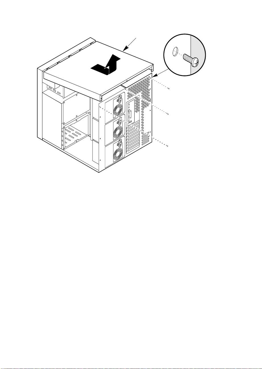
OM05256
1
2
1 Screw
2 Top cover
Figure 4-2. Top Cover
Replacing the Top Cover
See Figure 4-2.
1. Before replacing the top cover, make sure you did not leave any tools or
loose parts inside the chassis.
2. Ensure that interior cables are properly connected.
3. Position the top cover (Figure 4-2) over the chassis so that the tabs along
the front of the cover align with the slots in the top edge of the chassis.
4. Slide the cover toward the front of the system so that the tabs firmly
engage in the slots in the chassis.
5. Attach the cover to the chassis with the three screws you removed
earlier, and tighten them firmly (6.0 inch-pounds).
6. Replace both side covers. Connect all external cables and power cords
to the system.
M440LX Server System Product Guide
83
Page 84

Removing the Plastic Front Cover
See Figure 4-3.
1. Observe the warnings and cautions on page 3, “Safety Guidelines.”
2. Remove both side covers and the top cover, and set them aside
(page 80).
3. Remove the two screws from the front cover, and save them.
4. Unsnap the front cover from the chassis, and place it on a smooth
surface so that it doesn’t get scratched.
Replacing the Plastic Front Cover
See Figure 4-3.
1. Insert the plastic T-shaped tabs on the bottom front cover into the
T-shaped notches along bottom of the chassis. Then gently press the
cover onto the chassis until all tabs snap into place.
2. Attach the front cover to the chassis with the two screws you removed
earlier, and tighten them firmly (6.0 inch-pounds).
3. Replace the top cover and both side covers.
4. Connect all external cables and power cords to the system. (Some
systems have more than one power cord.)
84
Chapter 4 Working Inside Your System
Page 85

3
Figure 4-3. Plastic Front Cover
1 Screw
2 Plastic front cover
3 Plastic tab
1
2
OM05786
M440LX Server System Product Guide
85
Page 86
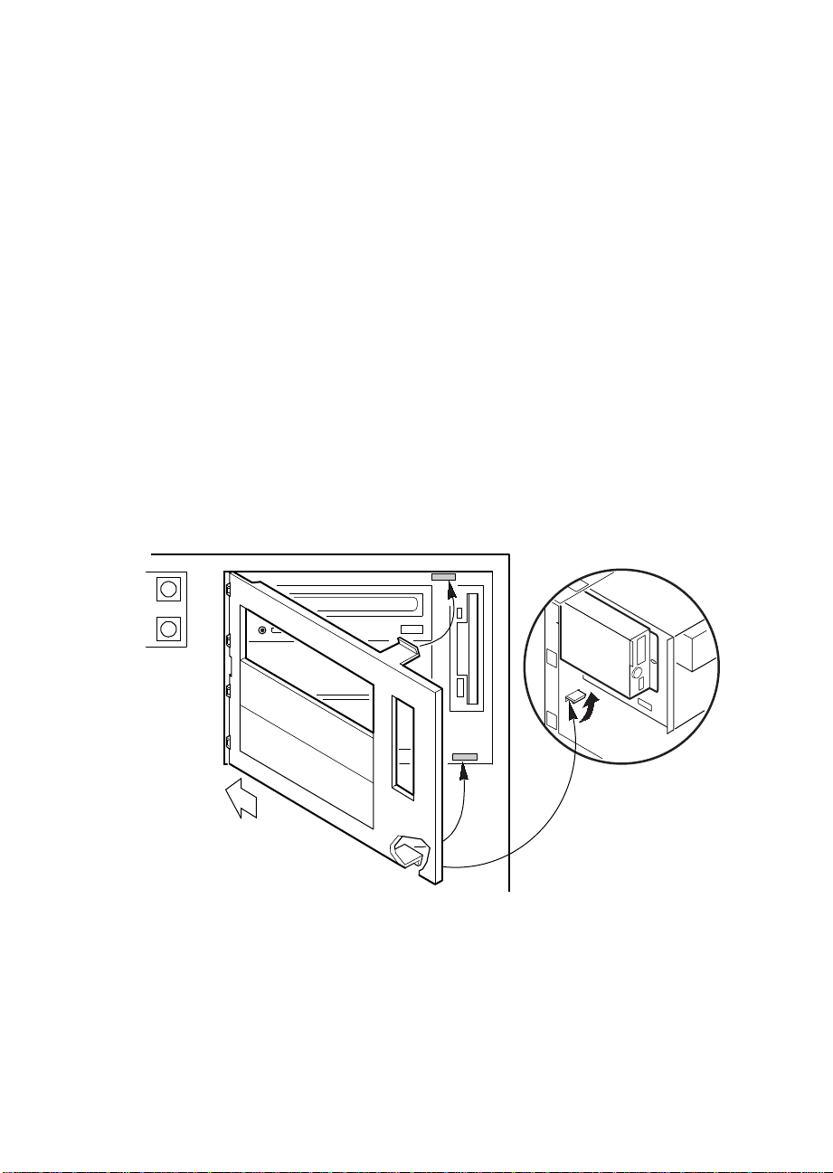
Removing the Snap-in Plastic Peripheral Bay Cover
See Figure 4-4.
1. Observe the warnings and cautions on page 3, “Safety Guidelines.”
2. Remove the right side cover (when viewed from the front, see page 80).
3. To remove the snap-in plastic peripheral bay cover, push up on the
bottom flexible tab below the 3.5-inch diskette drive. Then push the tab
toward the front of the system until you can grasp the lower right
corner of the cover.
CAUTION
!
▲
▲
Do not try to remove the snap-in peripheral bay cover by
inserting a screwdriver or other tool in the notch on the left
side of the cover. The cover may break.
4. Pull the lower right corner of the cover toward you with an upward
twisting motion to disengage the top flexible tab.
5. Remove the snap-in peripheral bay cover from the system, and place it
on a flat surface.
86
OM05778
Figure 4-4. Snap-in Plastic Peripheral Bay Cover
Chapter 4 Working Inside Your System
Page 87

Replacing the Snap-in Plastic Peripheral Bay Cover
See Figure 4-4.
1. Insert the rigid tabs on the plastic snap-in peripheral bay cover into the
notches along the inside edge of the plastic front panel.
2. Push the top right corner of the plastic cover toward the chassis with an
inward twisting motion to insert the top flexible tab in the slot above the
3.5-inch diskette drive.
3. Gently press on the cover until both the top and bottom flexible tabs
snap into place.
4. Replace the right side cover (page 81).
5. Connect all external cables and power cords to the system. (Some
systems have more than one power cord.)
M440LX Server System Product Guide
87
Page 88

Board Set
The system board supports two processor modules, a memory module, and
an RPX module.
CAUTION
!
▲
▲
The Pentium II processor is be extremely sensitive to ESD
and always requires careful handling. After removing the
module from its protective wrapper or from the system
board, place it heat sink side down on a nonconductive,
static-free surface. Do not slide the module over any
surface.
If you are upgrading a one-processor system with a second processor, you
must install a voltage regulator and remove the termination board from the
CPU1 slot.
Removing the Termination Board
See Figure 4-5.
1. Observe the warnings and cautions on page 3, “Safety Guidelines.”
2. Remove the left side cover (page 80).
3. Press the latches on the Terminator Latching Assembly (TLA) inward.
88
4. Pull the TLA out of the module retention bracket.
5. Holding the terminator board by its top edge, carefully rock it back and
forth until the edge connector pulls free.
Chapter 4 Working Inside Your System
Page 89
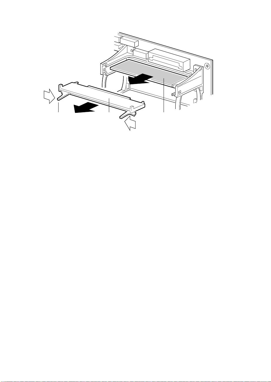
A B C
Figure 4-5. Removing a Termination Board
A Latch
B Terminator Latching Assembly
C Terminator Board
Installing a Voltage Regulator Module
See Figure 4-6.
1. Observe the warnings and cautions on page 3, “Safety Guidelines.”
2. Remove the left side cover (page 80).
3. Being careful not to touch the components or connector on the voltage
regulator module, remove it from its protective wrapper and place it on
a nonconductive, static-free surface.
4. Record the module ID information (may be a date code) in your
equipment log.
5. Hold the module by its top edge or upper corners and firmly press it
into the connector (Figure 4-6) on the system board until the lock tabs
click into place.
OM05773A
M440LX Server System Product Guide
89
Page 90

3
2
1
90
OM05774
Figure 4-6. Installing a Voltage Regulator Module
1 Module
2 Connector
3 Lock Tab
Chapter 4 Working Inside Your System
Page 91
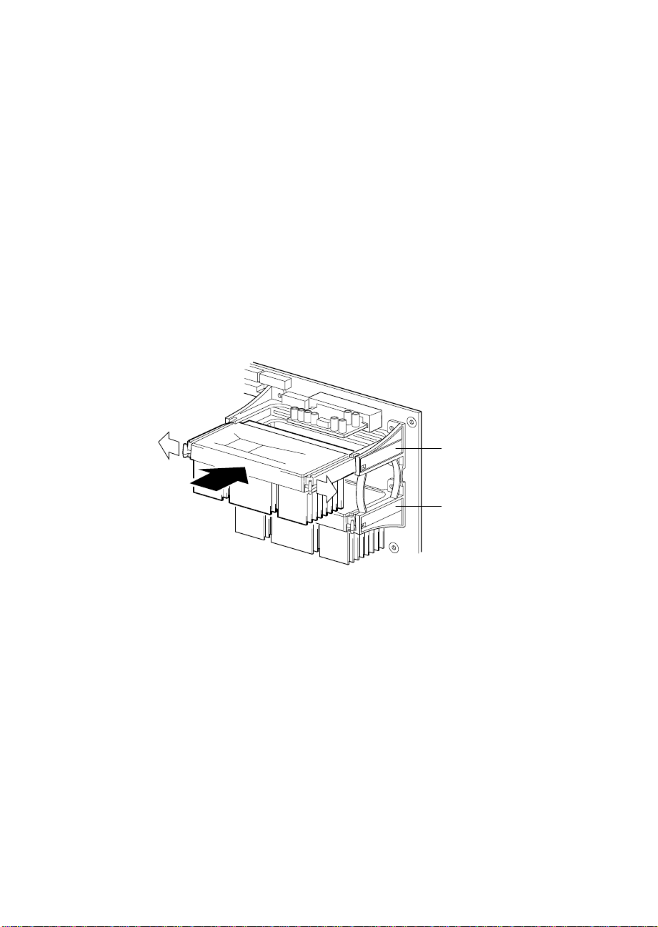
Installing a Pentium II Processor
See Figure 4-7.
1. Observe the warnings and cautions on page 3, “Safety Guidelines.”
2. Remove the left side cover (page 80).
3. Being careful not to touch the components or gold edge connectors on
the processor module, remove it from its protective wrapper and place
it heat-sink side down on a nonconductive, static-free surface.
4. Record the module serial number in your equipment log.
5. Press the locking tabs inward until they remain retracted.
6. Hold the module by its top edge or upper corners, and firmly press it
into the connector (Figure 4-7) on the system board. Press the locking
tabs outward so they engage the support bracket.
CPU1
Figure 4-7. Installing a Pentium II Processor
7. Replace the left side cover (page 81).
8. Run the SCU to configure the system. For information about running
the utility, see Chapter 3, "Configuring The System."
M440LX Server System Product Guide
CPU0
OM05775
91
Page 92

Removing a Pentium II Processor
See Figure 4-7.
1. Observe the warnings and cautions on page 3, “Safety Guidelines.”
2. Remove the left side cover (page 80).
3. Squeeze the locking tabs and pull the module free from the connector.
4. Store the module in an antistatic protective wrapper, or place it
processor-side up on a nonconductive, static-free surface.
Installing the Memory Module
See Figure 4-8.
1. Observe the warnings and cautions on page 3, “Safety Guidelines.”
2. Remove the left side cover (page 80).
3. Remove the rail.
4. Being careful not to touch the components or gold edge connectors on
the memory module, remove it from its protective wrapper and place it
socket-side up on a nonconductive, static-free surface.
5. Record the module serial number in your equipment log.
6. Hold the module by its top edge or upper corners, and firmly press it
into the connector (Figure 4-8) on the system board.
92
7. Install the rail.
Chapter 4 Working Inside Your System
Page 93

1
2
3
OM05760B
Figure 4-8. Installing the Memory Module
1 System board
2 Connector
3 Module
8. Run the SCU to configure the system. For information about running
the utility, see Chapter 3, "Configuring The System."
M440LX Server System Product Guide
93
Page 94

Removing the Memory Module
See Figure 4-8.
1. Observe the warnings and cautions on page 3, “Safety Guidelines.”
2. Remove the left side cover (page 80).
3. Remove the rail.
4. Holding the module by its top edge or upper corners, carefully rock it
back and forth until the edge connector pulls free.
5. Store the module in an antistatic protective wrapper, or place it Socket
side up on a nonconductive, static-free surface.
6. Install the rail.
Installing the RPX Module
See Figure 4-9.
1. Observe the warnings and cautions on page 3, “Safety Guidelines.”
2. Remove the left side cover (page 80).
3. Remove the RPX rail.
4. Being careful not to touch the components or gold edge connectors on
the RPX module, remove it from its protective wrapper and place it
component side up on a nonconductive, static-free surface.
94
5. Record the module serial number in your equipment log.
6. Plug in the RPX battery.
7. Hold the module by its top edge or upper corners, and firmly press it
into the connector (Figure 4-9) on the system board.
8. Install the rail.
Chapter 4 Working Inside Your System
Page 95

1
2
3
OM05760A
Figure 4-9. Installing the RPX Module
1 System board
2 Connector
3 Module
9. Run the SCU to configure the system. For information about running
the utility, see Chapter 3, "Configuring The System."
M440LX Server System Product Guide
95
Page 96

Removing the RPX Module
See Figure 4-9.
1. Observe the warnings and cautions on page 3, “Safety Guidelines.”
2. Remove the left side cover (page 80).
3. Remove the RPX rail.
4. Holding the module by its top edge or upper corners, carefully rock it
back and forth until the edge connector pulls free.
5. Unplug the RPX battery.
6. Store the module in an antistatic protective wrapper, or place it
component side up on a nonconductive, static-free surface.
7. Install the rail.
96
Chapter 4 Working Inside Your System
Page 97

Add-in Boards
The system board provides seven PCI bus master slots and three ISA bus
master slots. They accept any add-in PCI and ISA boards. One PCI
connector shares a common chassis I/O expansion slot with an ISA
connector; you can use either PCI slot or ISA in the slot, but not both.
CAUTIONS
!
▲
▲
Do not overload the system board by installing add-in
boards that draw excessive current. For expansion slot
current limitations, see Chapter 7, “Power System.”
Add-in boards can be extremely sensitive to ESD and
always require careful handling. After removing the board
from its protective wrapper or from the system board, place
it component-side up on a nonconductive, static-free
surface. Do not slide the board over any surface.
✏
Note
If you are installing or removing an ISA add-in board, you
must run the SCU to reconfigure the system. Running the
SCU is optional for a PCI add-in board.
M440LX Server System Product Guide
97
Page 98
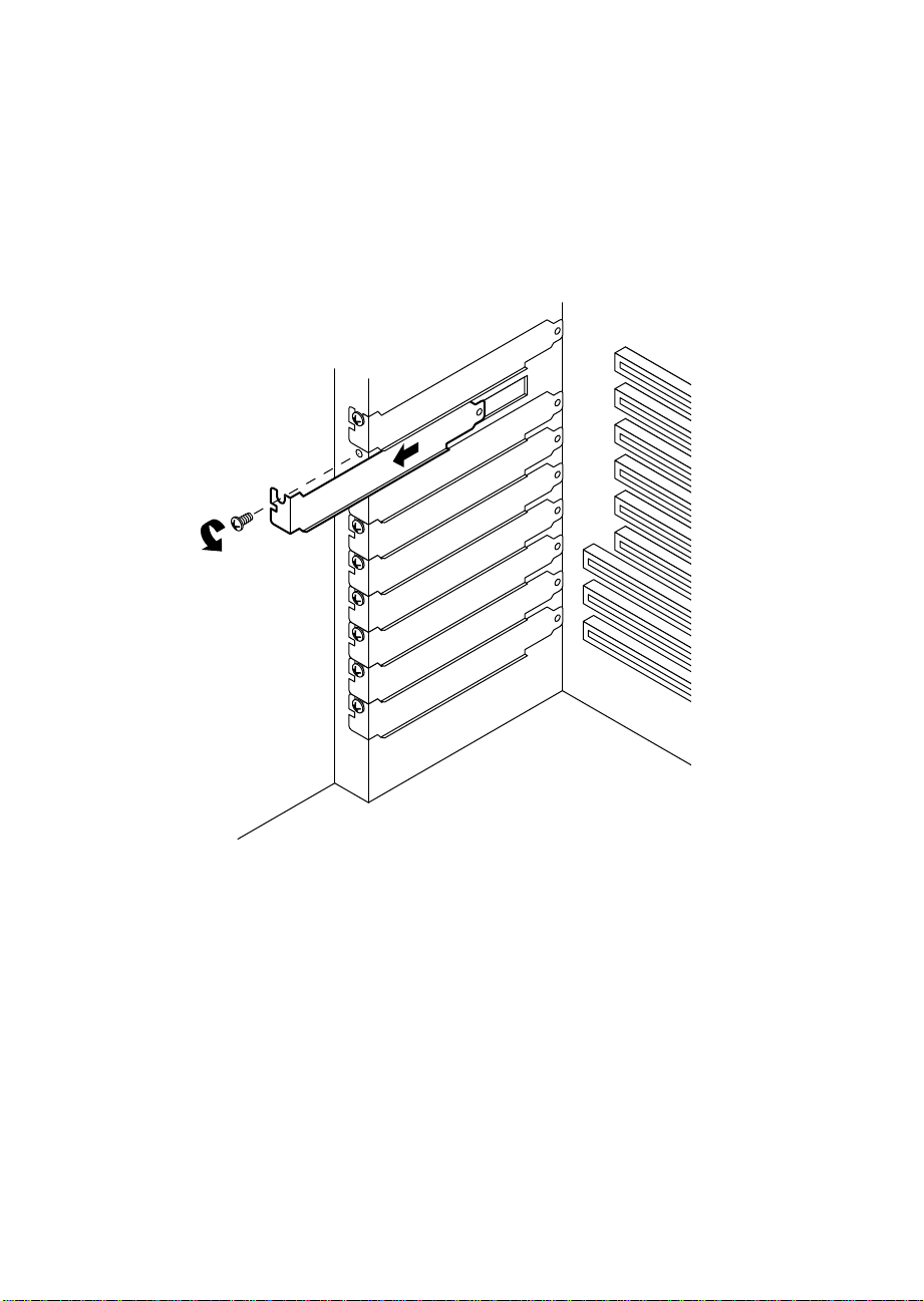
Installing an Add-in Board
See Figures 4-10, 4-11, and 4-12.
1. Observe the warnings and cautions on page 3, “Safety Guidelines.”
2. Remove the left side cover (page 80).
3. Remove and save the expansion slot screw and cover.
98
OM04638
Figure 4-10. Expansion Slot Cover
Chapter 4 Working Inside Your System
Page 99

4. Being careful not to touch the components or gold edge connectors on
the board, remove it from its protective wrapper and place it
component-side up on a nonconductive, antistatic surface.
5. Record the board serial number in your equipment log.
6. Set any jumpers or switches according to the board manufacturer's
instructions.
7. Hold the board by its top edge or upper corners, and firmly press it into
an expansion slot
tapered foot of the board retaining bracket must fit into the mating slot
in the expansion slot frame.
8. Align the rounded notch in the retaining bracket with the threaded hole
in the expansion slot frame. The retaining bracket fits into the space
that was occupied by the slot cover.
9. Insert the screw you removed earlier, and push the rounded notch up
against the screw. Tighten the screw firmly (6.0 inch-pounds) to
prevent the bracket from interfering with an adjacent one.
10. Replace the left side cover (page 81).
11. If you installed an ISA add-in board, run the SCU to reconfigure the
system. Running the SCU is optional for a PCI add-in board. For
information about running this utility, see Chapter 3, “Configuring The
System.”
on the system board (Figure 4-11 or Figure 4-12). The
M440LX Server System Product Guide
99
Page 100

OM04639
Figure 4-11. Installing an ISA Add-in Board, Component-side Up
100
Chapter 4 Working Inside Your System
 Loading...