

Intel SC5300AF2 - Server Platform - 0 MB RAM, Management Module Installation And User Manual
Page 1

Intel® Management Module
Installation and User’s Guide
Document P/N C81751-002
Page 2

Legal Information
Intel Corporation
This Intel Management Module Installation and User Guide as well as the software described in it is furnished under license
and may only be used or copied in accordance with the terms of the license. The information in this manual is furnished for
informational use only, is subject to change without notice, and should not be construed as a commitment by Intel
Corporation. Intel Corporation assumes no responsibility or liability for any errors or inaccuracies that may appear in this
document or any software that may be provided in association with this document.
Except as permitted by such license, no part of this document may be reproduced, stored in a retrieval system, or
transmitted in any form or by any means without the express written consent of Intel Corporation.
INFORMATION IN THIS DOCUMENT IS PROVIDED IN CONNECTION WITH INTEL® PRODUCTS. NO LICENSE,
EXPRESS OR IMPLIED, BY ESTOPPEL OR OTHERWISE, TO ANY INTELLECTUAL PROPERTY RIGHTS IS GRANTED
BY THIS DOCUMENT. EXCEPT AS PROVIDED IN INTEL'S TERMS AND CONDITIONS OF SALE FOR SUCH
PRODUCTS, INTEL ASSUMES NO LIABILITY WHATSOEVER, AND INTEL DISCLAIMS ANY EXPRESS OR IMPLIED
WARRANTY, RELATING TO SALE AND/OR USE OF INTEL PRODUCTS INCLUDING LIABILITY OR WARRANTIES
RELATING TO FITNESS FOR A PARTICULAR PURPOSE, MERCHANTABILITY, OR INFRINGEMENT OF ANY PATENT,
COPYRIGHT OR OTHER INTELLECTUAL PROPERTY RIGHT. Intel products are not intended for use in medical, life
saving, life sustaining applications.
Intel may make changes to specifications and product descriptions at any time, without notice.
The Intel® Server Board SE7520AF2, Intel® Server Board SE7520BD2, Intel® Server Board SE7520JR2, Intel®
Management Module—Professional Edition, and Intel® Management Module—Advanced Edition may contain design
defects or errors known as errata which may cause the product to deviate from published specifications. Current
characterized errata are available on request.
Intel, Pentium, Itanium, and Celeron are registered trademarks of Intel Corporation or its subsidiaries in the United States
and other countries.
*
Other names and brands may be claimed as the property of others.
Copyright © 2004, 2005 Intel Corporation.
All rights reserved.
2 Intel® Management Module Installation and User’s Guide
Page 3

Contents
Introduction 5
Intel® Management Module Features.....................................................................................5
Getting the Latest Information and Support............................................................................6
Platform Compatibility and System Requirements..................................................................6
Installation Procedures 8
Before You Begin....................................................................................................................8
Location of Intel Management Module Header.......................................................................8
Installing the Intel Management Module—Professional Edition............................................11
Removing the Intel Management Module—Professional Edition..........................................12
Installing the Intel Management Module—Advanced Edition................................................13
Removing the Intel Management Module—Advanced Edition..............................................16
Intel Advanced Remote Server Control 17
Email Alerting 18
Embedded SNMP 19
Configuring SNMP ................................................................................................................19
Using the BMC-Resident SNMP Agent.................................................................................19
Embedded CLI (Telnet) 21
Configuring the Embedded CLI (Telnet) Feature..................................................................21
Using the Embedded CLI (Telnet) Feature...........................................................................21
Embedded Web Server 22
Configuring the Embedded Web Server ...............................................................................22
Using the Embedded Web Server.........................................................................................22
Appendix A: Command Line Interface Syntax 26
References 31
Glossary 32
Intel® Management Module Installation and User’s Guide 3
Page 4

4 Intel® Management Module Installation and User’s Guide
Page 5

Introduction
The Intel® Management Module is an upgrade to the National Semiconductor PC87431 mini-BMC
®
management controller on the Intel
®
Intel
Server Board SE7520JR2, and Intel® Server Board SE8500HW4. The Intel Management
Module plugs into a connector on the server board. The Intel Management Module is available in
two versions:
• Professional Edition
• Advanced Edition
Intel® Management Module Features
Professional Edition Features
The Professional Edition includes the following features:
• All the features provided by the mBMC
• Support for IPMI v2.0 specification
• Additional sensors
• Temperature-based fan speed control by the BMC
• Additional FRU records are visible to the management controller and management software
applications (for example, Power Supply, DIMM, and hot-swap controller FRU’s).
• The size of the System Event Log (SEL) is increased from 92 entries to 3276 entries
• The number of BMC users is increased from one anonymous user to four users (each with
configurable user names and passwords on each LAN or Serial channel)
• The IPMI 2.0 serial features are supported. The serial port can be used for console
redirection, Terminal-mode CLI, dial paging, Serial Over LAN (SOL), and other
management functions.
• The Intelligent Chassis Management Bus (ICMB) is supported
• PCI SMBus is accessible to the management controller. This allows PCI add-in cards that
support manageability to log events to the System Event Log (SEL).
• BIOS logging of POST progress codes is added to the existing capability of logging only the
BIOS POST errors
• Front panel functionality is enhanced (See: Secure Mode Button Actions in the platform
Technical Product Specification)
• For systems with the SATA or SCSI hot-swap controller (HSC), the HSC sensors are visible
to server management software and HSC events are logged in the SEL.
Server Board SE7520AF2, Intel® Server Board SE7520BD2,
Intel® Management Module Installation and User’s Guide 5
Page 6

Advanced Edition Features
The Advanced Edition adds all the features listed above for the Professional Edition, plus the
following features:
rd
• BMC-resident SNMP support for out-of-band access using 3
party applications such as
Hewlett-Packard* OpenView*
• Embedded web server to access system health, view the SEL, and issue IPMI commands
• Embedded Command Line Interface (using a Telnet server running on the BMC) to allow
direct terminal access to the BMC
• Alerting via Email
®
• Intel
Advanced Remote Server Control adds remote KVM functionality
• High-speed access to a dedicated NIC for the BMC on the Advanced Edition module
The Intel Advanced Remote Server Control, email alerting, embedded CLI, embedded web,
BMC-resident SNMP agent, SOL, and other firmware-resident features are available Out-of-Band
(OOB). This means that these features are available even when the Operating System is not
running or the AC power is off.
Getting the Latest Information and Support
The latest information on each server board and Intel software is available at:
http://support.intel.com/support/motherboards/server
Platform Compatibility and System Requirements
The Intel Management Modules are compatible with the following Intel server boards:
• Intel Server Board SE7520AF2
• Intel Server Board SE7520BD2
• Intel Server Board SE7520JR2
• Intel Server Board SE8500HW4
Table 1 on page 7 lists the minimum system requirements.
6 Intel® Management Module Installation and User’s Guide
Page 7

Table 1. Minimum System Requirements
To use this feature…
Intel Advanced Remote
Server Control
Embedded Web Server Intel Management Module Advanced Edition installed on the managed
Embedded CLI (Telnet
Server)
Email Alerting Intel Management Module Advanced Edition installed on the managed
Serial Over LAN Intel Management Module Advanced Edition or Professional Edition
You will need…
ISM 8.20 Intel Advanced Remote Server Control component installed on the
Administration Console
Intel Management Module Advanced Edition installed on the managed
server
server
Intel Management Module Advanced Edition installed on the managed
server
server
installed on the managed server
Intel® Management Module Installation and User’s Guide 7
Page 8
Installation Procedures
Before You Begin
Read the “Warnings and Safety Cautions” section in the user’s guide for your server baseboard.
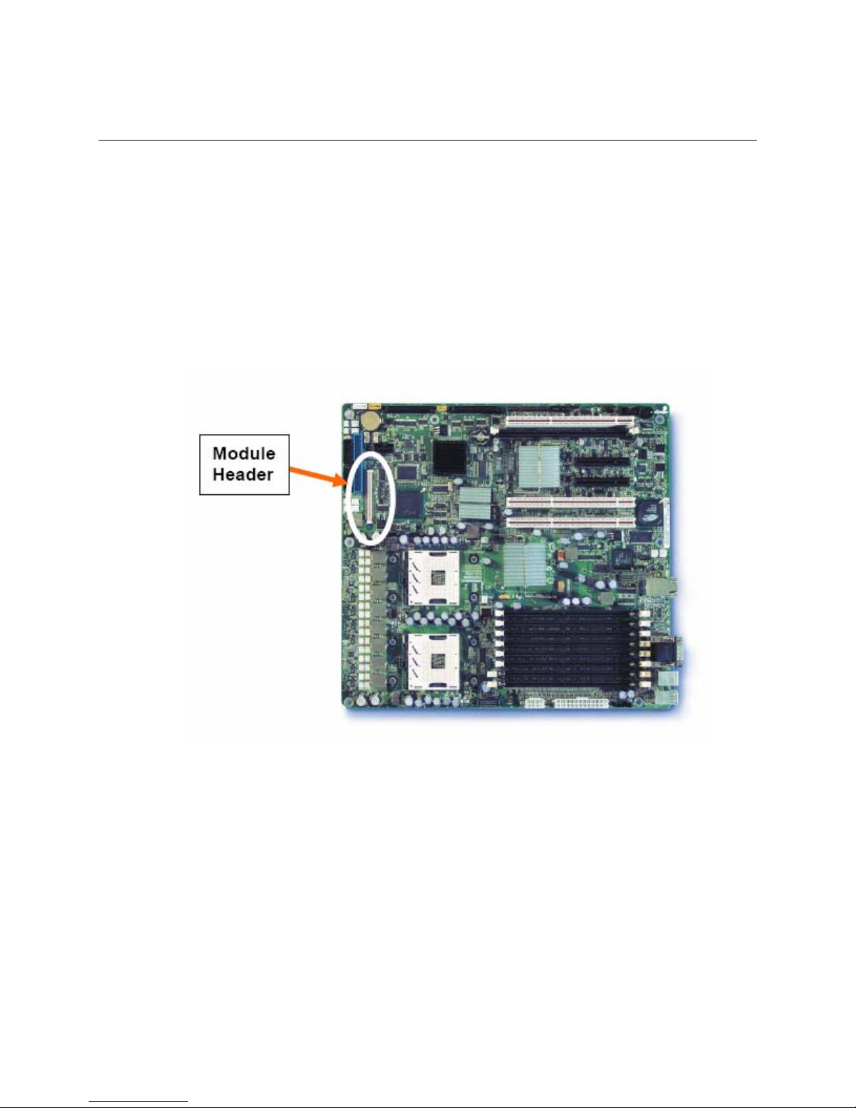
Location of Intel Management Module Header
The following illustrations show the location of the Intel Management Module header on the Intel
Server Board SE7520AF2, Intel Server Board SE7520BD2, Intel Server Board SE7520JR2, and
Intel Server Board SE8500HW4.
Figure 1. Location of Intel Management Module Connector on
8 Intel® Management Module Installation and User’s Guide
the Intel Server Board SE7520AF2
Page 9
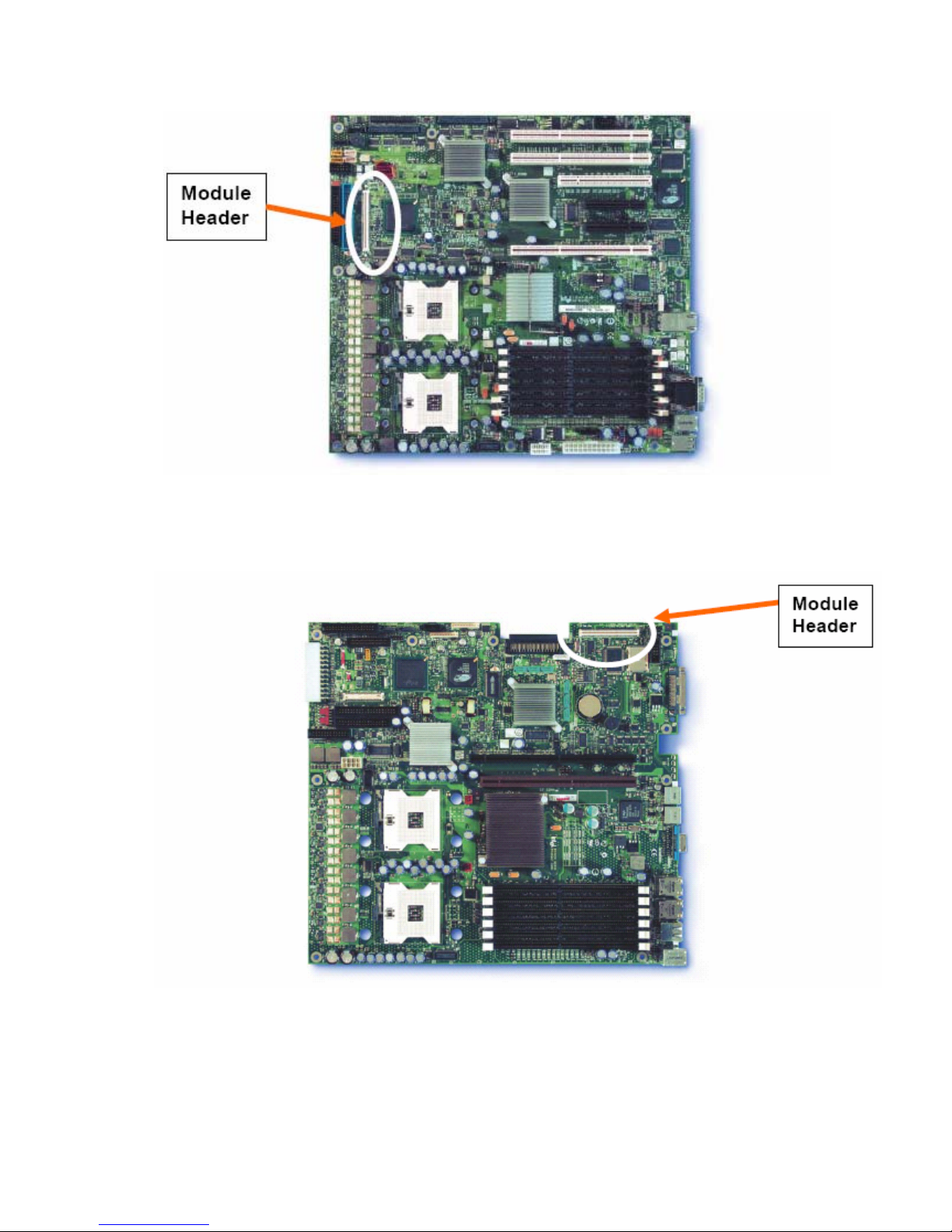
Figure 2. Location of Intel Management Module Connector on
the Intel Server Board SE7520BD2
Figure 3. Location of Intel Management Module Connector on
Intel® Management Module Installation and User’s Guide 9
the Intel Server Board SE7520JR2
Page 10
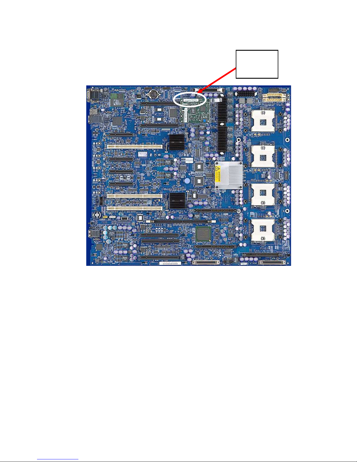
Module
Header
Figure 4. Location of Intel Management Module Connector on
the Intel Server Board SE8500HW4
10 Intel® Management Module Installation and User’s Guide
Page 11

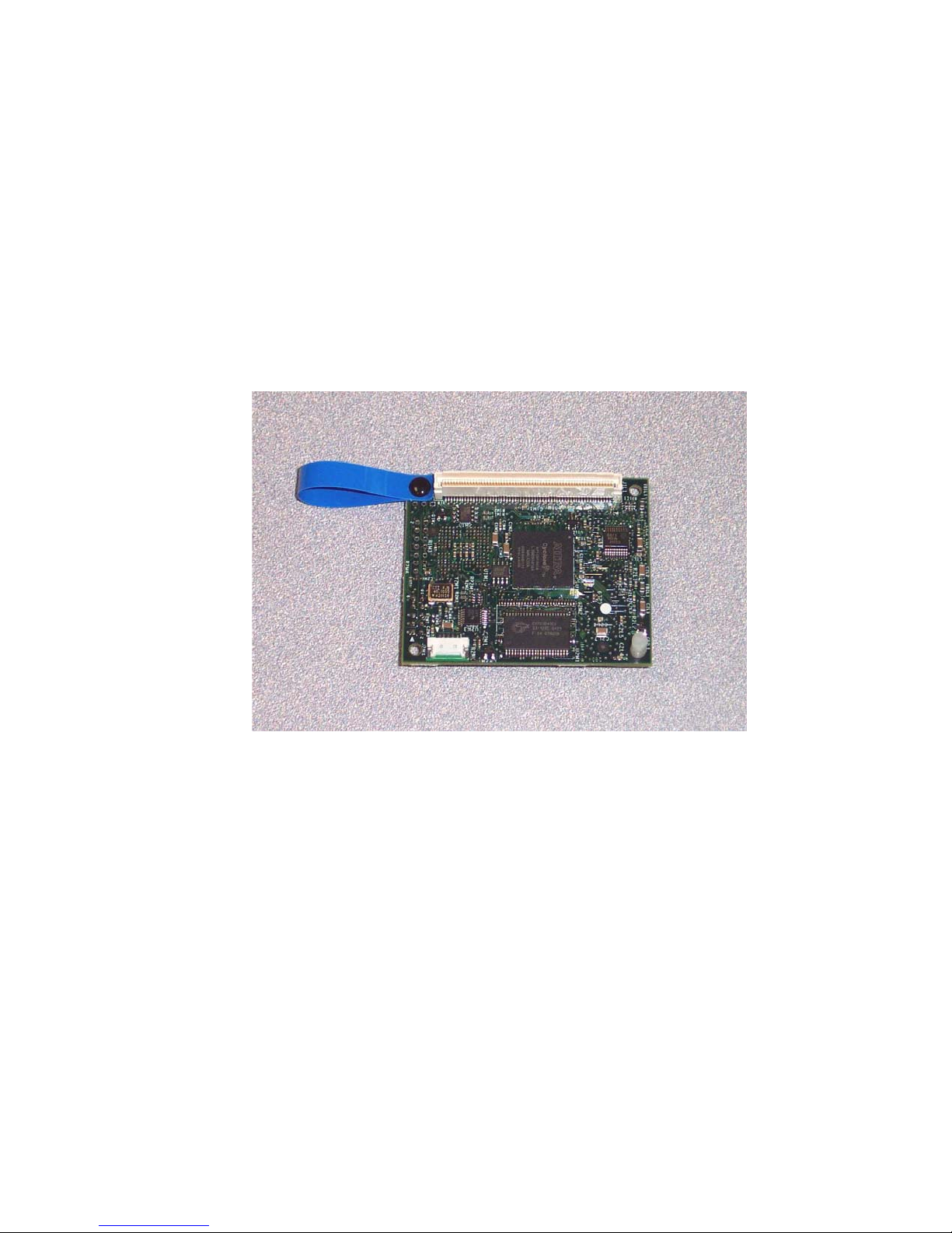
Installing the Intel Management Module—Professional Edition
The Professional Edition consists of the following components:
• 1 nylon standoff
®
• Intel
Management Module Professional Edition. The following illustration shows the
location of the standoff and retraction strap on the Professional Edition module (the location
is the same on the Advanced Edition module). The upper illustration shows the bottom of the
module. The lower illustration shows the top of the module.
KEY: A.) Location of the extraction strap
B.) Location of the nylon standoff
C.) Location of the module connector to the server board
B.
C.
A.
A.
B.
Figure 5. Location of the Connector, Extraction Strap, and Standoff on
the Intel Management Module (Professional Edition)
Intel® Management Module Installation and User’s Guide 11
Page 12

To prepare for the installation, you will need the following:
• The utilities for your server board (available on the Intel
®
Server Deployment Toolkit CD
shipped with your server board)
• The latest FRU/SDR package, firmware update files, and Release Notes from
http://support.intel.com/support/motherboards/server
.
To install the Professional Edition module, do the following:
1. Power down the system.
2. Remove AC power.
3. Open the chassis to gain access to the Intel Management Module Connector.
4. Insert the nylon standoff into the baseboard to support the Intel Management Module. Choose
the hole farthest away from the strap after the Intel Management Module is inserted into the
connector.
5. Align the Management Module over the baseboard connector and the nylon standoff.
6. Press down on the Management Module to fully seat the connector and standoff.
7. Close the chassis, reconnect the AC power, and power-on the system.
8. Update the firmware and FRU/SDR for your server board. Use the latest files and instructions
for your server board that you downloaded from
http://support.intel.com/support/motherboards/server
9. Install ISM 8.20 from the ISM 8 Installation CD, or run the Intel
.
®
Server Configuration Wizard
(SCW) from the Intel Server Deployment Toolkit CD to configure the new features on the
Professional Edition module.
Removing the Intel Management Module—Professional Edition
To remove the Professional Edition module, do the following:
1. Power down the system.
2. Remove AC power.
3. Open the chassis to gain access to the Intel Management module.
4. Pinch the end of the standoff and slightly raise the Management Module to disengage the
standoff. To avoid damage to the connector, do not lift the edge the board that is farthest from
the connector (near the standoff).
5. Using the strap attached to the module, gently pull up to slightly disengage the end of the
connector closest to the strap. Using your fingers, grasp the board near the other end of the
connector and gently rock the board back and forth until the connector is completely
disengaged.
6. Close the chassis and reconnect the AC power.
12 Intel® Management Module Installation and User’s Guide
Page 13
Installing the Intel Management Module—Advanced Edition
C
The Advanced Edition Module consists of the following components:
• 1 Nylon Standoff
®
• Intel
Management Module Advanced Edition
The following illustration shows the location of the standoff, connector, and retraction strap
on the Advanced Edition module.
KEY: A.) Location of the extraction strap
B.) Location of the nylon standoff
C.) Location of the module connector to the server board
A.
.
B.
Figure 6. Location of the Connector, Extraction Strap, and Standoff on
the Intel Management Module (Advanced Edition)
Intel® Management Module Installation and User’s Guide 13
Page 14

NOTE
This NIC card and associated hardware listed below are not used with the SE8500HW4 server
board, which has a dedicated system management NIC on the server baseboard.
• Intel Management Module Network Interface Card.
• 2 Screws
• Rear filler panel with LAN connection knockout (not required for SR1400 and SR2400
chassis)
The following illustration shows the network interface card, filler panel, and screws.
Figure 7. Intel Management Module Network Interface Card, Rear Filler Panel, and Screws
• 2 I2C Cables (one long and one short cable)
To prepare for the installation, you will need the following:
• The utilities for your server board (available on the Intel Server Deployment Toolkit CD
shipped with your server board)
• The latest FRU/SDR, firmware update files, and Release Notes (download from
http://support.intel.com/support/motherboards/server
• A Medium Phillips screwdriver to attach the NIC card to the rear filler panel
14 Intel® Management Module Installation and User’s Guide
)
Page 15

To install the Advanced Edition module, do the following:
1. Power down the system.
2. Remove AC power.
3. Open the chassis to gain access to the Intel Management Module Connector and the rear panel.
4. For Intel Server Chassis SR1400 or Intel Server Chassis SR2400 with Intel Server Board
SE7520JR2: follow the instructions in the chassis Product Guide to remove the Add-in Card
Riser. Insert one nylon standoff in the baseboard to support the Management Module.
5. If you are installing in a SE8500HW4 platform, skip this step. Connect the cable between the
Management Module and the NIC card. If you are installing the NIC in the SR1400 or SR2400
chassis, use the short cable, otherwise use the longer cable.
6. Align the Management Module over the baseboard connector and the nylon standoff.
7. Press down on the Management Module to fully seat the connector and standoff.
8. For Intel Server Chassis SR1400 or Intel Server Chassis SR2400 with Intel Server Board
SE7520JR2, install the NIC on the rear panel using 2 screws. The following illustration shows
the location of the network connector (NIC3) on the rear panel of the Intel Server Chassis
SR1400.
NIC3
Replace the Add-in Card Riser.
9. For all other chassis types, except
SE8500HW4 platforms:
a. Connect the NIC to the filler panel with two screws.
b. Install the NIC and filler panel in a full-height PCI rear panel slot.
10. Connect the LAN cable to the NIC.
11. Close the chassis, reconnect the AC power, and power-on the system.
12. Update the firmware and FRU/SDR for your server board. Use the latest files and instructions
for your server board that you downloaded from
http://support.intel.com/support/motherboards/server
.
13. For headless operation (no keyboard), enter BIOS Setup (press F2 during POST) and change
the “POST Error Pause” option to “disable.”
14. Run the Intel Server Configuration Wizard (SCW) from the Intel Server Deployment Toolkit
CD to configure the new features on the Advanced Edition module.
NOTE
To ensure that the NIC on the Advanced Edition module is properly configured, answer “No” to
the following SCW question: “Intel Server Manager Application software and/or agents will be
installed on this server.”
Intel® Management Module Installation and User’s Guide 15
Page 16

NOTE
If you want to use Intel Advanced Remote Server Control (the ISM remote keyboard, video, and
mouse software) with this IMM, when you run SCW, specify a static IP address for the NIC on the
Advanced Edition module.
15. Run the ISM 8 Installation CD to install the Embedded SNMP MIB file and Intel Remote
Server Control client viewer application.
Removing the Intel Management Module—Advanced Edition
To Remove the Advanced Edition module, do the following:
1. Power down the system.
2. Remove AC power.
3. Open the chassis to gain access to the Intel Management Module.
4. Disconnect the cable to the NIC.
5. Pinch the end of the standoff and slightly raise the Management Module to disengage the
standoff.
6. Using the strap attached to the module, gently pull up to disengage the connector. Using your
fingers, lift up the other end of the connector and gently rock the connector back and forth until
the connector is completely disengaged. To avoid damage to the connector, do not lift the edge
the board that is farthest from the connector.
7. Close-up the chassis and reconnect the AC power.
16 Intel® Management Module Installation and User’s Guide
Page 17

Intel Advanced Remote Server Control
The Intel Advanced Remote Server Control feature provides Keyboard, Video, Mouse (KVM)
redirection over the network to a remote client running the Intel Advanced Remote Server Control
viewer application.
Run the Intel Server Configuration Wizard (SCW) on the Intel Server Deployment Toolkit CD to
enable the KVM feature. To use Intel Advanced Remote Server Control with the Advance Edition
module, when you run SCW, specify a static IP address for the NIC on the IMM.
The client-side utility for using this feature is launched either from the Intel
(ISM) 8.20 console or from a web browser. Use the ISM 8 Installation CD to install this
component of ISM 8.20.
®
Server Manager
Intel® Management Module Installation and User’s Guide 17
Page 18

Email Alerting
Simple Mail Transport Protocol (SMTP) is a host-to-host email protocol over TCP. SMTP alerting
allows you to send simple email alerts to preconfigured email destinations.
Use the Intel Server Configuration Wizard to configure the email alerting feature. You can
configure the following parameters:
• Number of supported alert configurations
• Email From, To, and Subject lines
• Alerting machine name
The body of the alert message consists of the System Event Log (SEL) entry (English only) for the
event that caused the alert.
NOTE
Email alerting is only available on the network attached to the Advanced Edition module NIC.
18 Intel® Management Module Installation and User’s Guide
Page 19

Embedded SNMP
You can connect to the managed server and use either an OS-resident SNMP agent or the
Embedded (BMC-resident) SNMP agent. Table 2 summarizes the features available in the two
SNMP access methods.
Table 2. Features Available with BMC and OS Agents
Feature BMC SNMP Agent OS SNMP Agent
Access Sensor Data Yes Yes
View threshold settings Yes Yes
Modify threshold settings
(Voltage, Temperature, System Fan)
Read the SMBIOS tables No Yes
Provide overall system health status No Yes
SET Yes (Limited) Yes
SNMP access without OS running on
Managed Server
Uses dedicated NIC Yes No
No Yes
Yes No
Configuring SNMP
For instructions on installing and using the OS-specific SNMP Subagents, refer to the Installing
and Configuring the Intel® Server Manager 8 SNMP Subagents document
(SNMP_Subagent_Install_and_Config_Guide.pdf) on the ISM 8 Installation CD.
To use the BMC-resident SNMP agent, install the BMC.MIB file using the ISM 8 SNMP
installation option.
Run the Server Configuration Wizard (SCW) on the Intel Server Deployment Toolkit CD to
configure the BMC SNMP Agent. The SCW will allow the user to configure the following:
• Enable SNMP
• Configure the SNMP port number for Get/Set commands
• Configure LAN alerting for SNMP Traps
• Set the SNMP Trap destination
Using the BMC-Resident SNMP Agent
To use the BMC-resident SNMP Agent, do the following:
1. Connect the NIC on the Advanced Edition module to the network.
2. Launch your SNMP-aware network management station (for example, Hewlett-Packard’s
OpenView) on a remote administrative system.
Intel® Management Module Installation and User’s Guide 19
Page 20

3. Copy the BMC.MIB file from the Intel Server Deployment Toolkit CD to your local hard drive.
Load this MIB into your NMS application.
4. Set the SNMP community string to “public” to read the sensor data, or “private” to use the
SNMP SET commands.
The user has two SNMP SET commands available when using the BMC-resident SNMP agent:
• Set the SNMP-only machine name variable to help confirm which managed server is being
addressed by a particular SNMP request.
• Set Chassis ID LED to turn on/off the front panel ID LED.
20 Intel® Management Module Installation and User’s Guide
Page 21

Embedded CLI (Telnet)
Configuring the Embedded CLI (Telnet) Feature
Run the Server Configuration Wizard (SCW) on the Intel Server Deployment Toolkit CD to
configure the Embedded CLI Telnet Server.
The SCW allows you to:
• Enable the Telnet Server in firmware
• Configure the Telnet port number
Using the Embedded CLI (Telnet) Feature
The firmware on the Advanced Edition module includes a telnet server. The telnet server provides
you with both in-band and out-of-band monitoring and control of the server by using Intel’s
proprietary Command Line Interface (CLI) syntax called Common CLI (CCLI). The telnet server
also allows you to establish a Serial Over LAN (SOL) session.
To use the embedded CLI feature, do the following:
1. Connect to the Telnet server.
For example, to Telnet to a server at IP address 222.222.222.36 from the command prompt,
type the following:
Telnet 222.222.222.36
2. Log-in to the server. The Telnet server will ask for the BMC user name and password for
LAN channel 3 (this is the NIC attached to the Advanced Edition module). (Use the SCW to
configure the user names and passwords.)
The server responds with the CLI prompt:
CLI>
3. Type a CLI command (the CLI syntax is listed in Appendix A
CLI>health
The server return codes and responses are listed in Appendix A
on page 26). For example:
on page 26.
NOTE
The CLI syntax for the embedded Telnet server is slightly different than the syntax defined in the
IPMI 1.5 specification for terminal mode CLI.
Intel® Management Module Installation and User’s Guide 21
Page 22

Embedded Web Server
Configuring the Embedded Web Server
Run the Intel Server Configuration Wizard (SCW) from the Intel Server Deployment Toolkit CD to
configure the Embedded Web Server.
The SCW allows you to:
• Enable the web server in firmware
• Configure the HTTP Port number
Using the Embedded Web Server
Introduction
The Embedded Web Server has six firmware-resident web pages:
• System Summary Page—displays the overall system health and health indicators for
individual sensors
• System Event Log—displays selected number of records from the System Event Log
• Power—provides power and reset controls
• IPMI Command—accepts IPMI hex commands or Native CLI commands and returns a
response
• Configuration—provides configuration controls for the Embedded Web Server
• Help—provides on-line help
Each page has navigation links on the left side for quick navigation to another page plus an overall
health indicator (directly above the navigation links).
22 Intel® Management Module Installation and User’s Guide
Page 23

The following figure shows the System Summary Page.
Figure 8. System Summary Page for the Embedded Web Server
Using the Web Page Interface
To access the Embedded Web Server, do the following:
1. Go to the following URL:
http://hostname
where hostname is the IP address or domain name for the server.
If you have configured the port number to be some number other than port 80, add the port
number to the URL. If you encounter problems connecting to the server, try disabling
automatic configuration of the browser LAN settings.
2. The Embedded Web Server will prompt you for the BMC user name and password the first
time you connect to the server. To log-in as the anonymous user with a Null password, simply
leave the user name and password text boxes blank and press Enter.
[:portnumber]
NOTE
The Embedded Web Server checks the privilege level of the user before executing every command.
The Embedded Web Server will prompt you again if you have logged in with insufficient privilege
level to execute the requested command.
3. The Embedded Web Server will display the System Summary page after the user is
authenticated.
Intel® Management Module Installation and User’s Guide 23
Page 24

Using the Embedded Web Server Scripting Interface
The Embedded Web Server can be accessed from a scripting language such as Perl or JavaScript.
The client script sends a GET or POST request to the server. The server returns either an HTML
web page or an XML response.
To return an HTML Page, use one of the following formats:
http://hostname/ipmiPage?cmd=xx.xx.xx.xx.xx?onload=functionName
where xx.xx.xx.xx.xx is an IPMI 2.0 command in hexadecimal that is supported by the platform
http://hostname/webCmdPage?cmd=getSEL&first=num&last=num&onload=functionName
http://hostname/webCmdPage?cmd=clearSEL&onload=functionName
http://hostname/webCmdPage?cmd=changeVars&subcommand=value&onload=functionName
where subcommand is one of the following:
HealthyUpdateRate=num
WarningUpdateRate=num
CriticalUpdateRate=num
UsrUrl1=url (on-line help page URL)
UsrVal1=string (navigation bar label, the default is “help”)
UsrUrl2=url (the default is support.intel.com)
UsrVal2=string (navigation bar label, the default is “intel.com”)
3:Hostname=string (this only changes an internal web page variable)
3:Domainname=string (this only changes an internal web page variable)
The following syntax returns an XML response (see Table 3):
http://hostname/ipmiHex?cmd=xx.xx.xx.xx.xx
where xx represents one byte (two hex digits) of the IMPI 2.0 command (separate each pair of
hex digits with a period)
Table 3. Web Server Responses
Command Response
ipmiPage Argument 1 = completion code
Argument 2 = the command that was executed
Argument 3 = the command response
webCmdPage Argument 1=an error code of 0 or 1 indicates no error
Argument 2=an error string associated with the code
Argument 3= the response data
ipmiHex <ipmiResp completionCode=”YY”>XX-XX-XX…</ipmiResp>
(The completion code YY and the returned data bytes XX are defined in the IPMI
specification.)
24 Intel® Management Module Installation and User’s Guide
Page 25

HTML Example. In this example, the client-side page loads the page returned by the Embedded
Web Server into a frame.
<FRAMESET …><FRAME …>
<A HREF=http://222.222.39.10/ipmiPage?cmd=20.C0.64.07.00.00&onload=doOnLoad>
IPMI Command to check if web is enabled</A></FRAME>…</FRAMESET>
Perl Script Example. In the following example, a Perl script sends an HTTP GET to the server.
Use IO::Socket;
$sock = new IO::Socket::INET (PeerAddr => ‘222.222.39.10”,
PeerPort => 80,
Proto => ‘tcp’
);
die “Socket could not be created.” Unless $sock;
print $sock “GET /ipmiHex?cmd=20.C0.64.07.00.00 HTTP/1.0”
NOTE
The default authentication is MD5 Digest authentication. This means that command line scripting
tools must be able to handle Authentication failures and respond to the server requests.
Intel® Management Module Installation and User’s Guide 25
Page 26

Appendix A: Command Line Interface Syntax
The following Command Line Interface Syntax is used as the default for Terminal Mode CLI,
embedded CLI (using the BMC-based Telnet server), and the embedded HTTP server IPMI
Command page. Note that this syntax is slightly different than the IPMI 1.5 CLI syntax, or the CLI
syntax used with the dpccli proxy (an optional component of ISM 8.20). Table 4 lists the standard
return values. Table 5 lists the CLI command syntax.
Table 4. Standard Return Values for CLI Commands
• ok
• unsupported command
• unrecognized command
• command time-out
• insufficient privilege
• session in progress
Table 5. Command Line Interface Syntax
IPMI
Cmd
help
health User
Privilege
Level
Option(s)
-C <command>
Short
Description
Display list of valid
commands.
Returns a brief
description of
command
Display the health
of the target.
Output
IPMI Rev: x.x
FW Rev: xx.xx
Commands
…
Command: xx
PWR:zzz H:xx T:xx V:xx PS:xx C:xx
D:xx S:xx O:xx
Where:
PWR is system POWER state
H is overall Health
T is Temperature
V is Voltage
PS is Power Supply subsystem
C is cooling subsystem (Fans)
D is Hard Drive / RAID Subsystem
S is physical Security
O is Other (OEM)
26 Intel® Management Module Installation and User’s Guide
Page 27

Cmd
IPMI
Privilege
Level
Option(s)
Short
Description
Output
zzz is: "ON", "OFF" (soft-off or
mechanical off), "SLP" (sleep - used
when can't distinguish sleep level),
"S4", "S3", "S2", "S1", "??" (unknown)
and xx is: ok, nc, cr, nr, uf, or ??
where:
"ok" = OK (monitored parameters
within normal operating ranges)
"nc" = non-critical ('warning':
hardware outside normal operating
range)
"cr" = critical ('fatal': hardware
exceeding specified ratings)
"nr" = non-recoverable ('potential
damage': system hardware in
jeopardy or damaged)
"uf" = unspecified fault (fault detected,
but severity unspecified)
"??" = status not available/unknown
(typically because system power is
OFF)
-f
id Callback
boot Operator
-f
-console
reset Operator
-console
Display “full”
health status
Display the unique
identifier for this
target (UUID)
Attempts to reboot
the system using
OS shutdown by
default
Force boot, do not
attempt OS
shutdown
During boot,
switch to system
console output
Initiate a system
reset
During reset,
switch to system
console output
Health :xx
Temperature :xx
Voltage :xx
…
xxxxxxxx-xxxx-xxxx-xxxxxxxxxxxxxxxx
Intel® Management Module Installation and User’s Guide 27
Page 28

IPMI
Cmd
Privilege
Level
shutdown Operator
power Operator
Option(s)
Short
Description
Power off by
issuing an orderly
shutdown to the
OS
Force OS
-f
shutdown. (Switch
power off)
-on Switch power on
Set session to
-console
system console for
power-on
-off
Switch power off
(no OS shutdown)
Switch power off,
-cycle
then on (no OS
shutdown)
Display target’s
-state
current power
state
Output
See Note at the end of the table.
ON
OFF
console
(Only
Telnet
Callback
allows this
command)
exit (quit) Callback
logon
(Only
Terminal
Mode
Callback
allows this
command
set)
-u <username>
-n
-p <password>
End current
session
Switch the session
to system console.
“~.“ switches back
to CLI mode.
End current
session
Start a session
28 Intel® Management Module Installation and User’s Guide
Page 29

Cmd
IPMI
Privilege
Level
Option(s)
Short
Description
Output
network Operator
-p <params>
interrupt Operator
-console
version Callback
Displays the
current network
channel
configuration of
the BMC. If not
LAN channel, it
uses the primary
NIC channel
Display the
requested
parameter ( mac |
ip | subnet |
gateway ).
Causes the BMC
to generate an
IPMI diagnostic
interrupt (NMI for
IA-32 systems)
Switches to
console mode and
issues the
interrupt
Displays the
Native CLI version
number
IP Address: x.x.x.x
IP Address Source: (Static| DHCP |
BIOS | Other)
MAC Address: xx:xx:xx:xx:xx:xx
Subnet Mask: x.x.x.x
Gateway: x.x.x.x
Native CLI version x.x.
displaylog User
-all All SEL records
-a | -d
- s <first> <last>
clearlog User
identify
Operator Activate a local
Display SEL
records.
Ascending or
Descending
(default) order
Displays a set of
SEL records
Clears SEL
records
indicator to identify
target system (if
supported by
hardware)
Hex characters for each record,
separated by linefeed characters.
Intel® Management Module Installation and User’s Guide 29
Page 30

Cmd
IPMI
Privilege
Level
Option(s)
Short
Description
Output
-on [#] Switch indicator
on; turn off in #
seconds
-off Switch indicator
off
-state Display current
state of indicator
ON (Application)
ON (Button)
OFF
NOTE
Performing a graceful OS shutdown requires that an Intel supplied OS agent be present. If this
agent is not present or is unable to/does not respond after 7 seconds, an error message will be
displayed for the user and the command will terminate, no reset or power-off will be performed.
Graceful shutdown commands will not perform hard resets or power off if OS shutdown does not
complete.
30 Intel® Management Module Installation and User’s Guide
Page 31

References
• Intel® Server Board SE7520BD2 Technical Product Specification (available on
support.intel.com)
• Intel® Server Board SE7520JR2 Technical Product Specification (available on
support.intel.com)
• Intel® Server Board SE7520AF2 Technical Product Specification (available on
support.intel.com)
• Intel® Server Board SE7520AF2 User Guide (provided with the server board and available
on support.intel.com)
• Intel® Server Board SE7520JR2 User Guide (provided with the server board and available
on support.intel.com)
• Intel® Server Board SE7520BN2 User Guide (provided with the server board and available
on support.intel.com)
• Intel® Server Board SE8500HW4 User Guide (provided with the server board and available
on support.intel.com)
• Getting Started with Intel® Server Manager 8 (ISM 8) (ism_getting_started_guide.pdf). This
document is installed by the ISM installer from the ISM CD provided with the server board.
• Installing and Configuring the Intel® Server Manager 8 SNMP Subagents
(SNMP_Subagent_Install_and_Config_Guide.pdf). This document is installed by the ISM
installer from the ISM CD provided with the server board.
• IPMI—Intelligent Platform Management Interface Specification Second Generation v2.0, see
http://support.intel.com/support/motherboards/server
for the latest specification and errata.
Intel® Management Module Installation and User’s Guide 31
Page 32

Glossary
Term Definition
BIOS Basic Input Output System
BMC Baseboard Management Controller
CLI Command Line Interface
DIMM Dual In-line Memory Module
FRU F ield Replaceable Unit
HSC Hot-swap Controller
I2C Inter-Integrated Circuit Bus
ICMB Intelligent Chassis Management Bus
ID Identification
IPMI Intelligent Platform Mana gement Interface
ISM Intel® Server Manager
KVM Keyboard Video Mouse
LED Light Emitting Diode
mBMC mini-Baseboard Management Controller (National Semicon ductor PC87431)
MIB Management Information Base
NIC Network Interface Card
NMS Network Management Station
OOB Out of Band (management of the server without the server Operating System)
PCI Peripheral Component Interconnect bus
SATA Serial ATA (Advanced Technology Attachment)
SDR Sensor Data Record
SEL System Event Log
SCSI Small Computer System Interface
SCW Intel® Server Configuration Wizard
SNMP Simple Network Management Protocol
SMBus System Management Bus
SMTP Simple Mail Transfer Protocol
TPS Technical Product Specification
32 Intel® Management Module Installation and User’s Guide
 Loading...