

Page 1
Intel® Server Products and Solutions
Intel® Server Board
M10JNP2SB
User Guide
An overview of product features, functions, architecture,
support specifications, and instructions
for essential component installation.
Rev 1.1
November 2019
M10JNP2SB
Page 2

<Blank page>
Page 3

Intel® Server Board M10JNP2SB User Guide
3
Document Revision History
Date
Revision
Changes
October 2019
1.0
First release.
October 2019
1.01
Added product regulatory compliance table.
November 2019
1.1
Chapter 3 - Added Supported processors
Page 4

Intel® Server Board M10JNP2SB User Guide
4
Disclaimers
Intel technologies’ features and benefits depend on system configuration and may require enabled hardware, software, or service
activation. Learn more at Intel.com, or from the OEM or retailer.
You may not use or facilitate the use of this document in connection with any infringement or other legal analysis concerning Intel
products described herein. You agree to grant Intel a non-exclusive, royalty-free license to any patent claim thereafter drafted which
includes subject matter disclosed herein.
No license (express or implied, by estoppel or otherwise) to any intellectual property rights is granted by this document.
The products described may contain design defects or errors known as errata which may cause the product to deviate from
published specifications. Current characterized errata are available on request.
Intel disclaims all express and implied warranties, including without limitation, the implied warranties of merchantability, fitness
for a particular purpose, and non-infringement, as well as any warranty arising from course of performance, course of dealing, or
usage in trade.
Intel warranties that this product will perform to its published specifications. However, all computer systems are inherently subject to
unpredictable system behavior under various environmental and other conditions.
This product is not intended to be the sole source for any critical data and the user must maintain a verified backup. Failure to do
so or to comply with other user notices in the product user guide and specification documents may result in loss of or access to
data.
Copies of documents which have an order number and are referenced in this document may be obtained by calling 1-800-548-4725
or by visiting www.intel.com/design/literature.htm.
Intel and the Intel logo, are trademarks of Intel Corporation or its subsidiaries in the U.S. and/or other countries.
*Other names and brands may be claimed as the property of others.
Copyright © Intel Corporation. All rights reserved.
Page 5
Intel® Server Board M10JNP2SB User Guide
5
Product Safety Overview
Heed safety instructions: Before working with your server product, whether you are using this guide or any
other resource as a reference, pay close attention to the safety instructions. You must adhere to the
assembly instructions in this guide to ensure and maintain compliance with existing product certifications
and approvals. Use only the described, regulated components specified in this guide. Use of other
products/components will void the UL listing and other regulatory approvals of the product and will most
likely result in noncompliance with product regulations in the region(s) in which the product is sold.
Hazardous conditions, devices and cables: Hazardous electrical conditions may be present on power,
telephone, and communication cables. Turn off the system and disconnect all telecommunications systems,
networks, and modems attached to it before performing any service. Otherwise, personal injury or
equipment damage can result.
Installing or removing jumpers: A jumper is a small plastic encased conductor that slips over two jumper
pins. Some jumpers have a small tab on top that you can grip with your fingertips or with a pair of fine needle
nosed pliers. If your jumpers do not have such a tab, take care when using needle nosed pliers to remove or
install a jumper; grip the narrow sides of the jumper with the pliers, never the wide sides. Gripping the wide
sides can damage the contacts inside the jumper, causing intermittent problems with the function controlled
by that jumper. Take care to grip with, but not squeeze, the pliers or other tool you use to remove a jumper,
or you may bend or break the pins on the board.
Electrostatic Discharge (ESD)
Electrostatic discharge can cause damage to your computer or the components within it. ESD can occur
without the user feeling a shock while working inside the system chassis or while improperly handling
electronic devices like processors, memory or other storage devices, and add-in cards.
Intel recommends the following steps be taken when performing any procedures described within this
document or while performing service to any computer system.
• Where available, all system integration and/or service should be performed at a properly equipped ESD
workstation.
• Wear ESD protective gear like a grounded antistatic wrist strap, sole grounders, and/or conductive
shoes.
• Wear an anti-static smock or gown to cover any clothing that may generate an electrostatic charge.
• Remove all jewelry.
• Disconnect all power cables and cords before opening the Server Chassis
• Power down the system and remove power feed from the Server Board before performing any
integration or service
• Touch any unpainted metal surface of the chassis before performing any integration or service.
• Hold all circuit boards and other electronic components by their edges only.
• After removing electronic devices from the system or from their protective packaging, place them
component side up on to a grounded anti-static surface or conductive foam pad. Do not place electronic
devices on to the outside of any protective packaging.
Page 6

Intel® Server Board M10JNP2SB User Guide
6
Table of Contents
1. Introduction ............................................................................................................................................................... 10
1.1 Intel Server Board Use Disclaimer .......................................................................................................................... 10
2. Server Board Overview ............................................................................................................................................ 11
2.1 Server Board Features Overview ............................................................................................................................. 11
2.2 Server Board Component / Feature Identification ........................................................................................... 13
2.3 Server Board Mechanical Drawings ........................................................................................................................ 14
2.4 Product Architecture Overview ................................................................................................................................ 18
3. Processor Support .................................................................................................................................................... 19
3.1 Processor Features ........................................................................................................................................................ 20
3.1.1 Intel® Xeon® E-2100 processor family.......................................................... Error! Bookmark not defined.
3.1.2 Intel® Xeon® E-2200 processor family.......................................................... Error! Bookmark not defined.
4. Memory Support ....................................................................................................................................................... 21
4.1 Supported Memory ....................................................................................................................................................... 21
4.2 General Memory Population Rules ......................................................................................................................... 22
4.3 Memory RAS Features .................................................................................................................................................. 22
5. Server Board I/O ....................................................................................................................................................... 23
5.1 PCIe Add-In Card Support .......................................................................................................................................... 23
5.1.1 PCIe* Enumeration and Allocation ......................................................................................................................... 23
5.2 1U One-Slot PCIe Riser Card Option (iPC – JNP1URISER) ............................................................................ 24
5.3 Networking ........................................................................................................................................................................ 24
5.4 USB ....................................................................................................................................................................................... 25
5.4.1 External USB 3.1 Connectors .................................................................................................................................... 25
5.4.2 Front Panel USB 3.1 Connector ............................................................................................................................... 25
5.5 Onboard SATA Support .............................................................................................................................................. 26
5.5.1 SATADOM support ........................................................................................................................................................ 26
6. Server Management ................................................................................................................................................. 27
6.1 Shared Management Interface ................................................................................................................................. 27
6.2 Embedded Web Server ................................................................................................................................................ 27
7. On-Board Connector/Header Pin-Out Overview .............................................................................................. 29
7.1 Power Connectors ......................................................................................................................................................... 29
7.2 Onboard Storage Connectors ................................................................................................................................... 30
7.2.1 SATA 6 Gbps Connectors ........................................................................................................................................... 30
7.2.2 SATADOM 6 Gbps Connectors ................................................................................................................................. 30
7.2.3 SATA SGPIO Connector ............................................................................................................................................... 30
7.3 Fan Connectors ............................................................................................................................................................... 31
7.3.1 System Fan Connectors ............................................................................................................................................... 31
7.3.2 Processor Fan Connectors ......................................................................................................................................... 31
7.4 Front Panel Headers and Connectors ................................................................................................................... 31
7.4.1 Front Panel Header ....................................................................................................................................................... 31
7.4.2 Front Panel USB 3.1 Connector ............................................................................................................................... 31
Page 7

Intel® Server Board M10JNP2SB User Guide
7
7.5 Dedicated LAN Activity LED Headers ..................................................................................................................... 32
7.6 Other Headers and Connectors ............................................................................................................................... 32
7.6.1 Serial Port Connectors ................................................................................................................................................. 32
7.6.2 Power Supply Monitoring Interface (PSMI) Connector .................................................................................. 33
7.6.3 IPMB Header ..................................................................................................................................................................... 33
7.6.4 Chassis Intrusion Header ............................................................................................................................................ 33
7.6.5 ID LED Header .................................................................................................................................................................. 33
8. Reset and Recovery Jumpers ................................................................................................................................. 34
8.1 Clear CMOS Jumper Block ......................................................................................................................................... 34
8.2 BIOS Recovery Jumper ................................................................................................................................................ 35
9. Server Board and Essential System Component Installation and Removal ............................................... 36
9.1 Installing the Server Board ......................................................................................................................................... 37
9.2 Server Board Removal ................................................................................................................................................. 37
9.3 Installing the Processor ............................................................................................................................................... 38
9.4 Processor Heat Sink Installation .............................................................................................................................. 41
9.5 Heat Sink Removal ......................................................................................................................................................... 42
9.6 Removing the Processor ............................................................................................................................................. 43
9.7 Memory (DIMM) Installation ...................................................................................................................................... 43
9.8 Memory (DIMM) Removal............................................................................................................................................ 43
9.9 Connecting SATA Drives ............................................................................................................................................. 44
9.10 Removing SATA Drives ................................................................................................................................................ 44
9.11 Connecting System Fans ............................................................................................................................................. 45
9.12 Disconnecting System Fans ....................................................................................................................................... 46
Appendix A. Usage Tips ............................................................................................................................................... 47
Appendix B. Getting Help ............................................................................................................................................ 48
Appendix C. POST Code Errors .................................................................................................................................. 49
Appendix D. Additional References .......................................................................................................................... 58
Appendix E. Safety Instructions ................................................................................................................................ 59
Appendix F. Safety and Regulatory Certifications ................................................................................................. 69
Appendix G. Statement Of Volatility ........................................................................................................................ 72
Glossary ............................................................................................................................................................................. 74
List of Figures
Figure 1. Intel® Server Board M10JNP2SB ..................................................................................................................................... 11
Figure 2. Server board component / feature identification ..................................................................................................... 13
Figure 3. Server board mounting holes ........................................................................................................................................... 14
Figure 4. Component height restrictions ........................................................................................................................................ 15
Figure 5. Major components and connectors 1 of 2 .................................................................................................................. 16
Figure 6. Major components and connectors 2 of 2 .................................................................................................................. 17
Figure 7. Intel® Server Board M10JNP2SB block diagram ....................................................................................................... 18
Page 8

Intel® Server Board M10JNP2SB User Guide
8
Figure 8. Memory subsystem architecture ..................................................................................................................................... 21
Figure 9. DIMM slot identification ...................................................................................................................................................... 21
Figure 10. PCIe slot identification ...................................................................................................................................................... 23
Figure 11. 1U one-slot PCIe* riser card option (iPC – JNP1Uriser) ...................................................................................... 24
Figure 12. Rear networking ports ....................................................................................................................................................... 24
Figure 13. External USB 3.1 Gen2 ports .......................................................................................................................................... 25
Figure 14. Front panel USB 3.0 connector ..................................................................................................................................... 26
Figure 15. SATADOM connector pinout .......................................................................................................................................... 26
Figure 16. BMC embedded web server user interface ............................................................................................................... 28
Figure 17. Board jumper identification ............................................................................................................................................ 34
Figure 18. Server board mounting hole location ......................................................................................................................... 36
Figure 19. Removing the socket protection cap .......................................................................................................................... 38
Figure 20. Opening the socket lever ................................................................................................................................................. 38
Figure 21. Opening the processor load plate ................................................................................................................................ 39
Figure 22. Installing the processor .................................................................................................................................................... 39
Figure 23. Closing the load plate ........................................................................................................................................................ 40
Figure 24. Closing the socket lever .................................................................................................................................................... 40
Figure 25. Installing the heat sink ...................................................................................................................................................... 41
Figure 26. Connecting the fan cable ................................................................................................................................................. 41
Figure 27. Removing the fan cable .................................................................................................................................................... 42
Figure 28. Removing the heat sink ..................................................................................................................................................... 42
Figure 29. DIMM installation ................................................................................................................................................................. 43
Figure 30. DIMM removal ....................................................................................................................................................................... 43
Figure 31. Attaching SATA cables ...................................................................................................................................................... 44
Figure 32. Removing SATA cables ..................................................................................................................................................... 44
Figure 33. System fan connector identification ........................................................................................................................... 45
Figure 34. Connecting system fan cables ....................................................................................................................................... 45
Figure 35. Removing system fan cables .......................................................................................................................................... 46
List of Tables
Table 1. Intel® Server Board M10JNP2SB features/specifications ...................................................................................... 11
Table 2. Intel® Xeon® E-2200 processor family features list ................................................................................................... 19
Table 3. Intel® Xeon® E-2100 processor family features list ................................................................................................... 19
Table 4. DIMM population recommendations .............................................................................................................................. 22
Table 5. Memory RAS features ............................................................................................................................................................ 22
Table 6. One-slot PCIe* riser card slot description ..................................................................................................................... 24
Table 7. 10/100/1000 Mbps LAN link/activity LED matrix ...................................................................................................... 25
Table 8 PWR1 pin-out ............................................................................................................................................................................. 29
Table 9. PWR2 pin-out ............................................................................................................................................................................ 29
Table 10. SATA connector pin-out .................................................................................................................................................... 30
Page 9

Intel® Server Board M10JNP2SB User Guide
9
Table 11. SATADOM connector pin-out .......................................................................................................................................... 30
Table 12. SGPIO connector pin-out .................................................................................................................................................. 30
Table 13. System fan connector pin-out......................................................................................................................................... 31
Table 14. Processor fan connector pin-out ................................................................................................................................... 31
Table 15. Front panel header pin-out .............................................................................................................................................. 31
Table 16. Front panel USB 3.1 connector pinout ........................................................................................................................ 31
Table 17. LAN 3 activity LED header ................................................................................................................................................. 32
Table 18. LAN 4 activity LED header ................................................................................................................................................. 32
Table 19. TPM header pin-out ............................................................................................................................................................. 32
Table 20. COM1 port pin-out ............................................................................................................................................................... 32
Table 21. COM2 port pin-out ............................................................................................................................................................... 33
Table 22. PSMI connector pin-out ..................................................................................................................................................... 33
Table 23. IPMB header pin-out ........................................................................................................................................................... 33
Table 24. Chassis intrusion header pin-out ................................................................................................................................... 33
Table 25. ID LED header pin-out ........................................................................................................................................................ 33
Table 26. PEI phase .................................................................................................................................................................................. 50
Table 27. Product safety compliance ............................................................................................................................................... 69
Table 28. Product EMC compliance .................................................................................................................................................. 69
Table 29. Product regulatory compliance markings .................................................................................................................. 70
Table 30. Product regulatory compliance ...................................................................................................................................... 71
Table 31. Server board components ................................................................................................................................................ 73
Page 10

Intel® Server Board M10JNP2SB User Guide
10
1. Introduction
This user guide provides a high level overview of the features, functions, and architecture of the Intel® Server
Board M10JNP2SB. This document replaces the document previously known as the Technical Product
Specification (TPS).
This guide is divided in two main parts going from chapters 2 to 8 providing information about the server
board features and functions, followed by instructions on how to install or service essential system
components on chapter 9.
For additional information about this server board, refer to the documents listed in Appendix D.
1.1 Intel Server Board Use Disclaimer
Intel Corporation server boards support add-in peripherals and contain a number of high-density VLSI and
power delivery components that need adequate airflow to cool. It is the responsibility of the system
integrator to consult vendor datasheets and operating parameters to determine the amount of airflow
required for a specific system configuration and operating environment. Intel Corporation cannot be held
responsible if components fail or the server board does not operate correctly when used outside any of its
published operating or non-operating limits.
Page 11

Intel® Server Board M10JNP2SB User Guide
11
2. Server Board Overview
The Intel® Server Board M10JNP2SB is a monolithic printed circuit board assembly with features for data
center and office environments running multiple applications under a continuous work load. This server
board is designed to support the Intel® Xeon® E 2200 processor family.
Figure 1. Intel® Server Board M10JNP2SB
2.1 Server Board Features Overview
Table 1. Intel® Server Board M10JNP2SB features/specifications
Feature
Description
Processor support
• One LGA1151 processor socket
• Supports one of the following processors:
o Intel® Xeon E-2224 processor
o Intel® Xeon E-2236 processor
o Intel® Xeon E-2278G processor
• Maximum supported Thermal Design Power (TDP) of up to 95 W
Note: Server Systems based on this server board may support a lower maximum Thermal
Design Power (TDP). Consult chassis vendor specifications for maximum supported processor
TDP limits.
Memory
• Four DIMM Slots
• Two memory channels
• DDR4 UDIMM ECC, 2666 MT/s, 1.2V
• Up to 128GB total installed memory
Chipset
Intel® C246 Chipset
Network Ports
• Four 1GbE Base-T, RJ45
• One dedicated management port, RJ45
Onboard Storage Support
• Six SATA 6 Gbps ports (6 Gb/s, 3 Gb/s and 1.5 Gb/s transfer rates are supported)
• Two 7-pin SATA-DOM connectors
Page 12

Intel® Server Board M10JNP2SB User Guide
12
Feature
Description
Embedded SATA software RAID
• Intel® RSTe
PCIe* Add-in Card Slots
• Slot 1: PCIe* 3.0 x8 slot (x4 electrical)
• Slot 2: PCIe* 3.0 x8 slot (x8 electrical)
• Slot 3: PCIe* 3.0 x16 slot (x8 electrical)
Riser Card Support
: Support for one PCIe 3.0 riser card on PCIe slot 3. (Sold separately. Optional Intel Accessory)
Video
• Integrated 2D video controller
• 16 MB of DDR4 video memory
• One DB-15 external connector
• Two External Display Port connectors
USB
• Four external USB 3.1 Gen2 ports
• One 2x10 pin connector providing front panel support for (2) USB 3.1 Gen1 ports
Serial Port
• Two internal DH-10 serial port connectors
Server Management
• Integrated baseboard management controller, IPMI 2.0 compliant
• Dedicated RJ45 management port
• Shared management interface
Security
• Trusted platform module 2.0 support (China Version) – iPC JNPTPMCH
(accessory option)
• Trusted platform module 2.0 support (Rest of World) – iPC JNPTPM
(accessory option)
System Fan Support
• Two 4-pin processor fan headers
• Six 6-pin front system fan headers
• One 4-pin rear system fan header
Front Panel Support
• One 2x12 pin SSI front panel header
Page 13
Intel® Server Board M10JNP2SB User Guide
13
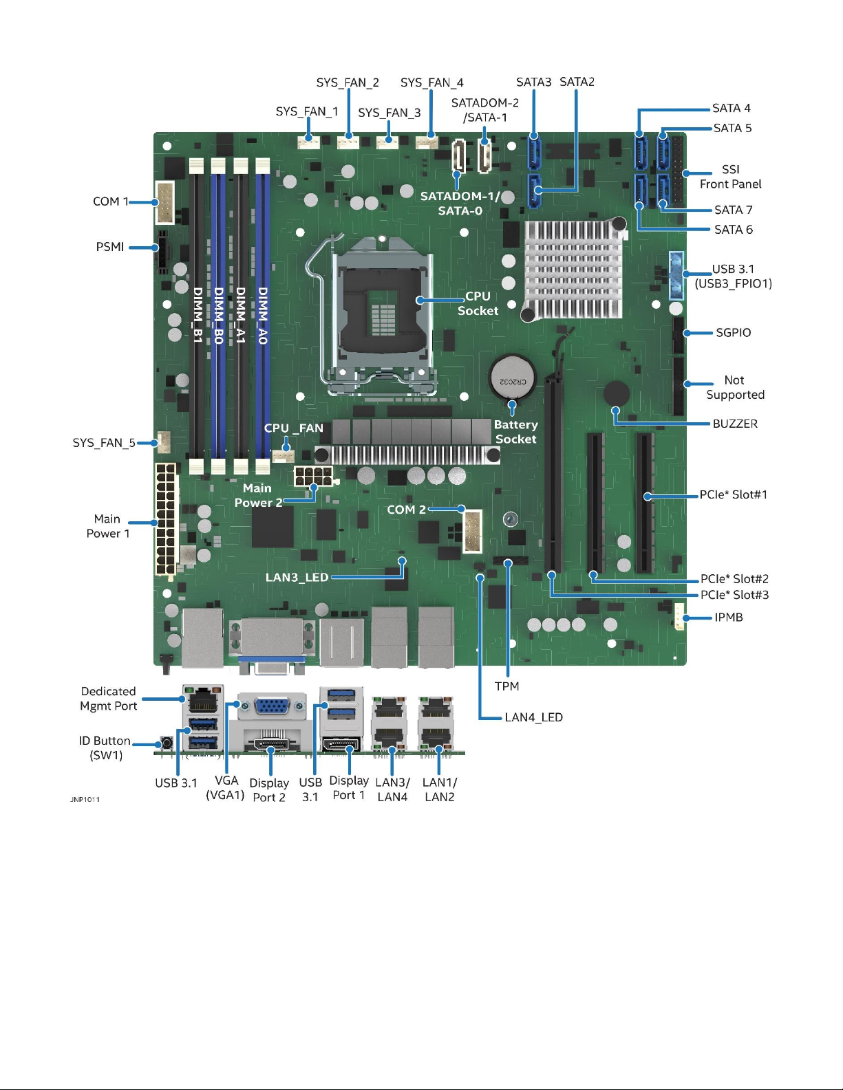
2.2 Server Board Component / Feature Identification
Figure 2. Server board component / feature identification
Page 14
Intel® Server Board M10JNP2SB User Guide
14
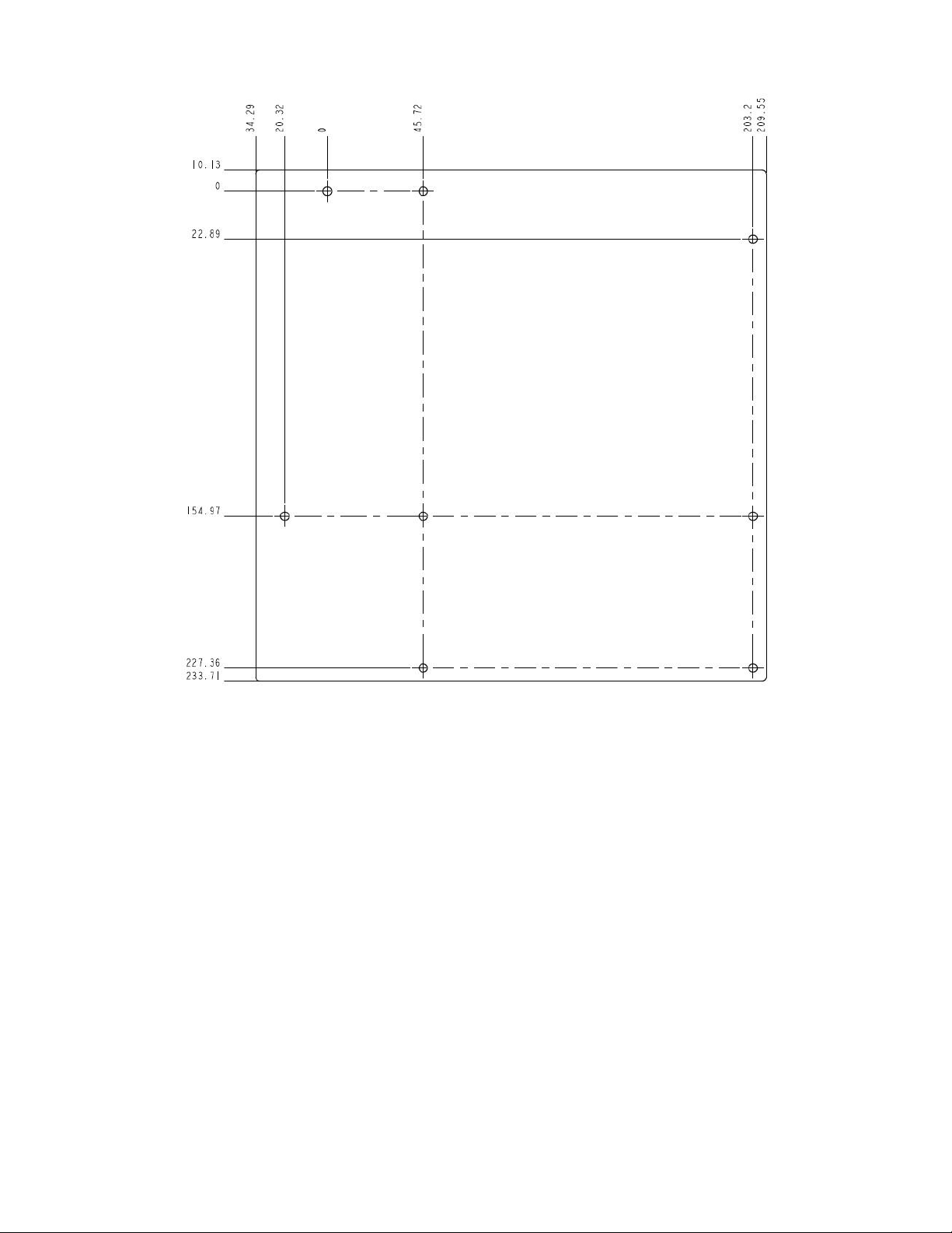
2.3 Server Board Mechanical Drawings
Figure 3. Server board mounting holes
Page 15
Intel® Server Board M10JNP2SB User Guide
15
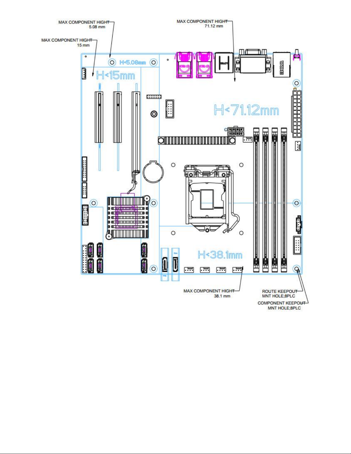
Figure 4. Component height restrictions
Page 16

Intel® Server Board M10JNP2SB User Guide
16
Figure 5. Major components and connectors 1 of 2
Page 17

Intel® Server Board M10JNP2SB User Guide
17
Figure 6. Major components and connectors 2 of 2
Page 18
Intel® Server Board M10JNP2SB User Guide
18
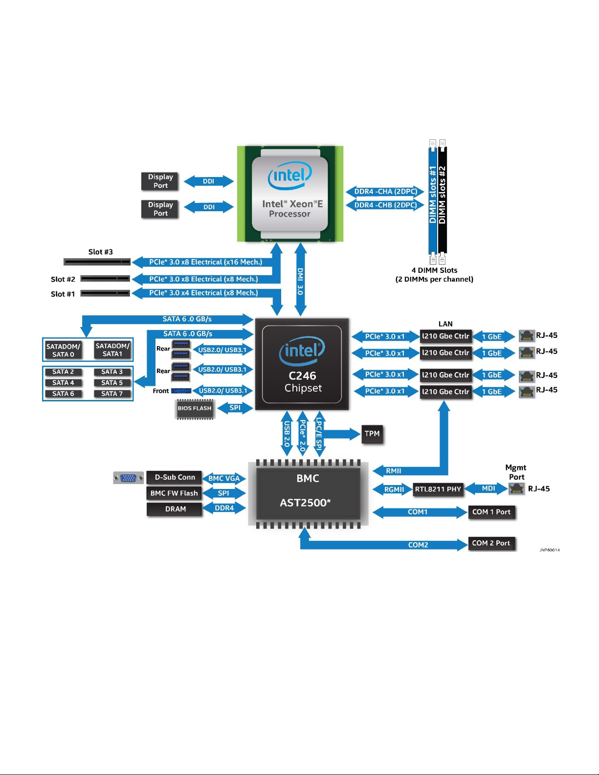
2.4 Product Architecture Overview
The architecture of Intel® Server Board M10JNP2SB is developed around the integrated features and
functions of the Intel® Xeon® E-2200 processor family, the Intel® C246 chipset (PCH), Intel® Ethernet
Controller I210, and the ASPEED* AST2500 baseboard management controller (BMC).
Figure 7 provides an overview of the server board architecture, showing the features and interconnects of
each of the major sub-system components.
Figure 7. Intel® Server Board M10JNP2SB block diagram
Page 19

Intel® Server Board M10JNP2SB User Guide
19
3. Processor Support
The server board includes one LGA1151 processor socket compatible with select models from the Intel®
Xeon® E-2100 and Intel® Xeon® E-2200 processor families with a maximum Thermal Design Power (TDP) of
95 W.
The Intel Server Board M10JNP2SB has been validated to support the following Intel processors:
• Intel® Xeon E-2104G Processor
• Intel® Xeon E-2124 Processor
• Intel® Xeon E-2124G Processor
• Intel® Xeon E-2126G Processor
• Intel® Xeon E-2134 Processor
• Intel® Xeon E-2136 Processor
• Intel® Xeon E-2146G Processor
• Intel® Xeon E-2174G Processor
• Intel® Xeon E-2176G Processor
• Intel® Xeon E-2186G Processor
• Intel® Xeon E-2224 Processor
• Intel® Xeon E-2236 Processor
• Intel® Xeon E-2278G Processor
Table 3 and Table 2 provide a comparison of specifications between the supported processors.
Table 2. Intel® Xeon® E-2100 processor family features list
SKU
Cores/threads
Base
Speed
(GHz)
Max Intel®
Turbo Boost
Technology 2.0
Speed (GHz)
Intel® UHD
Graphics
P630
Intel®
Smart
Cache
(MB)
E-2186G
6/12
3.8
4.7
Yes
12
E-2176G
6/12
3.7
4.7
Yes
12
E-2174G
4/8
3.8
4.7
Yes
8
E-2146G
6/12
3.5
4.5
Yes
12
E-2144G
4/8
3.6
4.5
Yes
8
E-2136
6/12
3.3
4.5
No
12
E-2134
4/8
3.5
4.5
No
8
E-2126G
6/12
3.3
4.5
Yes
12
E-2124G
4/8
3.4
4.5
Yes
8
E-2124
4/8
3.3
4.3
No
8
E-2104G
4
3.2
N/A
Yes
8
Table 3. Intel® Xeon® E-2200 processor family features list
Features
Intel® Xeon® E-2224
Processor
Intel® Xeon® E-2236
Processor
Intel® Xeon® E-2278G
Processor
Cores/Threads
4/4
6/12
8/16
Max Turbo Frequency
4.7 Ghz
4.8 Ghz
5.0 Ghz
Base Frequency
3.5 Ghz
3.4 Ghz
3.8 Ghz
Intel® Smart Cache
8 Mb
12 Mb
12 Mb
Intel® UHD Graphics
P360
N/A
P360
DDR4 ECC UDIMM
128 Gb
128 Gb
128 Gb
Page 20

Intel® Server Board M10JNP2SB User Guide
20
3.1 Processor Features
The Intel® Xeon® E-2100 and Intel® Xeon® E-2200 processor families combine several key system
components into a single processor package, and include the following features:
• Intel® Virtualization Technology (Intel® VT-x)
• Intel® Active Management Technology 11.0 (Intel® AMT)
• Intel® Trusted Execution Technology (Intel® TXT)
• Intel® Streaming SIMD Extensions 4.2 (Intel® SSE4.2)
• Intel® Hyperthreading Technology (Intel® HT Technology)
• Intel® 64 Architecture
• Execute Disable Bit
• Intel® Turbo Boost Technology 2.0
• Intel® Advanced Vector Extensions 2 (Intel® AVX2
• Intel® Advanced Encryption Standards New Instructions (Intel® AES-NI)
• PCLMULQDQ (Perform Carry Less Multiplication Quad word) instruction
• Intel® Secure Key
• Intel® Transactional Synchronization Extensions (Intel® TSX-NI)
• PAIR – Power Aware Interrupt Routing
• SMEP – Supervisor Mode Execution Protection
• Intel® Boot Guard
• Intel® Software Guard Extensions (Intel® SGX)
• Intel Memory Protection Extensions (Intel® MPX)
• GMM Scoring Accelerator
• Intel® Processor Trace (Intel® PT)
• High Definition Content Protection (HDCP) 2.2
Note: Feature availability may vary between processor SKUs.
Refer to the Intel® Server Board M10JNP2SB Configuration Guide for a complete list of tested hardware.
Page 21
Intel® Server Board M10JNP2SB User Guide
21
4. Memory Support
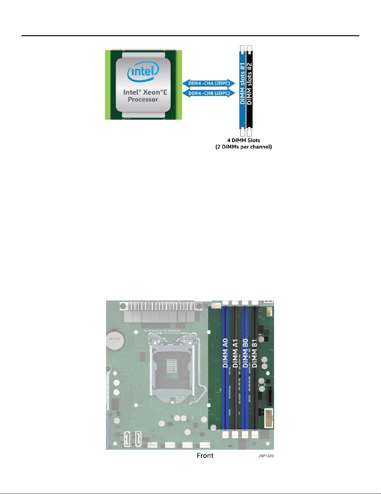
Figure 8. Memory subsystem architecture
The Intel® Xeon® E-2200 processor family includes an Integrated Memory Controller (IMC) capable of
supporting two memory channels that can accommodate up to two DIMM slots per channel. On the Intel®
Server Board M10JNP2SB, a total of four DIMM slots are provided as shown in Figure 9.
4.1 Supported Memory
The server board supports the following:
• Only DDR4 DIMMs are supported
• Only Error Correction Code (ECC) enabled UDIMMs are supported
• Total installed system memory of up to 128GB
• DIMM speeds of 2666/2400 MT/s
• DIMMs organized as Single Rank (SR) or Dual Rank (DR)
The following illustration shows the location of the DIMM slots on the server board.
Figure 9. DIMM slot identification
Page 22
Intel® Server Board M10JNP2SB User Guide
22
4.2 General Memory Population Rules
The following memory population rules apply when installing DIMMs:
• When only one DIMM is used in the channels A or B, it must be populated in the black DIMM slot.
• Mixing DIMMs of a different type or rank organization is not supported
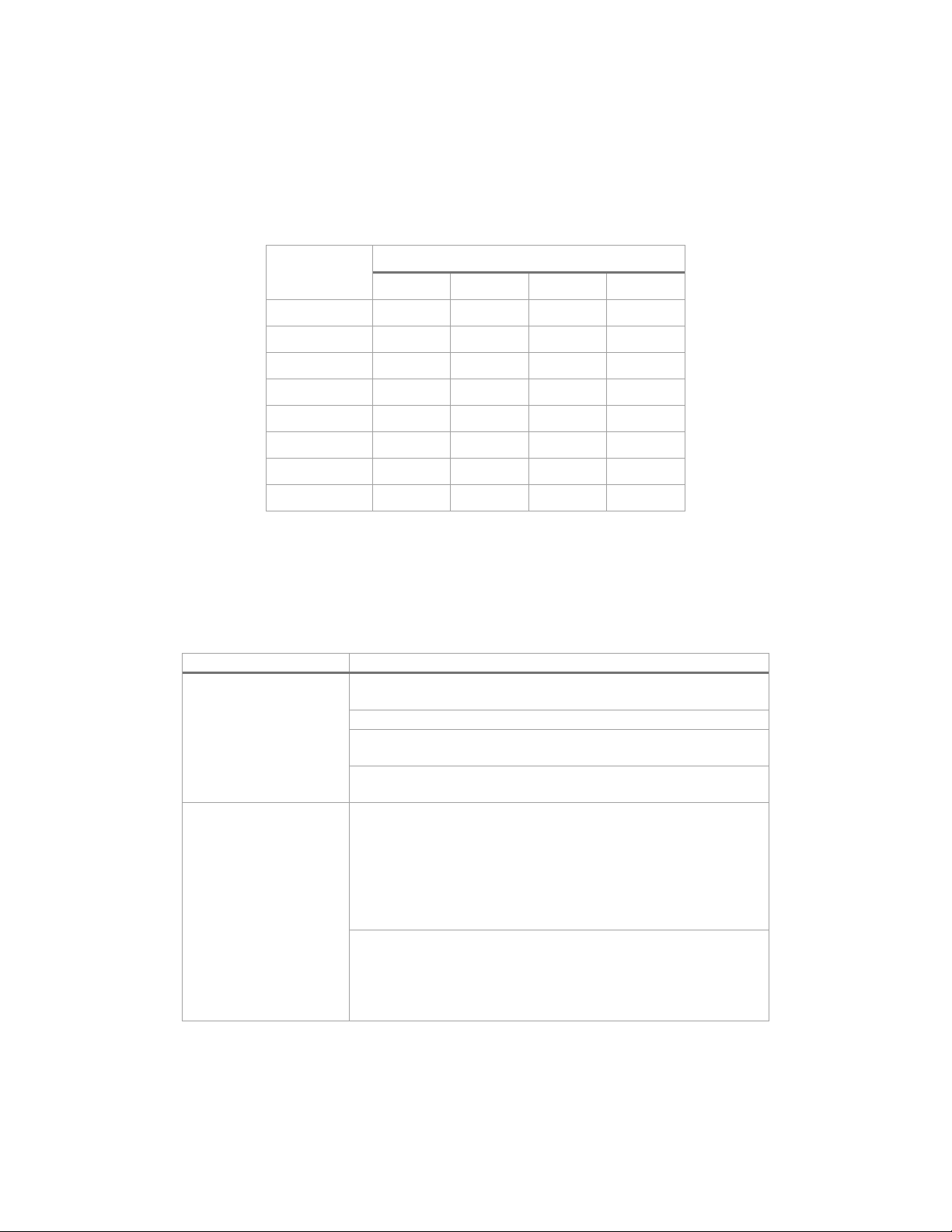
Table 4 lists the recommended DIMM populations for the server board.
Table 4. DIMM population recommendations
# of installed
DIMMs
DIMM Slot
DIMM_A0
DIMM_A1
DIMM_B0
DIMM_B1
1
2
1
2
2
3
3
4
4.3 Memory RAS Features
Each processor within the Intel® Xeon® E-2200 processor family has support for advanced memory RAS
features as defined in Table 5.
Table 5. Memory RAS features
RAS Feature
Description
Device Data Correction
x8 Single Device Data Correction (SDDC) via static virtual
lockstep (Applicable to x8 DRAM DIMMs)
Adaptive Data Correction (SR) (Applicable to x4 DRAM DIMMs)
x8 Single Device Data Correction + 1 bit (SDDC+1) (Applicable
to x8 DRAM DIMMs)
SDDDC + 1, and ADDDC (MR) + 1 (Applicable to x4 DRAM
DIMMs)
Memory Mirroring
Full Memory Mirroring: An intra IMC method of keeping a
duplicate (secondary or mirrored) copy of the contents of
memory as a redundant backup for use if the primary memory
fails. The mirrored copy of the memory is stored in memory of
the same processor socket's IMC. Dynamic (without reboot)
failover to the mirrored DIMMs is transparent to the OS and
applications.
Address Range/Partial Memory Mirroring: Provides further intra
socket granularity to mirroring of memory by allowing the
firmware or OS to determine a range of memory addresses to
be mirrored, leaving the rest of the memory in the socket in
non-mirror mode.
Page 23

Intel® Server Board M10JNP2SB User Guide
23
5. Server Board I/O
5.1 PCIe Add-In Card Support
The server board provides three PCI Express* (PCIe*) slots labeled: “PCIe#1”, “PCIe#2”, and “PCIe#3”. The
PCIe* interface of the Intel® Server Board M10JNP2SB is fully compliant with the PCIe* Base Specification,
Revision 3.0 supporting the following PCIe* bit rates: 3.0 (8.0 GT/s), 2.0 (5.0 GT/s), and 1.0 (2.5 GT/s).
PCIe add-in card slots and their properties are as follows:
• Slot 1: PCIe* 3.0 x8 slot (x4 electrical)
• Slot 2: PCIe* 3.0 x8 slot (x8 electrical)
• Slot 3: PCIe* 3.0 x16 slot (x8 electrical)
Figure 10. PCIe slot identification
5.1.1 PCIe* Enumeration and Allocation
The BIOS assigns PCI bus numbers in a depth-first hierarchy, in accordance with the PCI Local Bus
Specification, Revision 3.0. The bus number is incremented when the BIOS encounters a PCI-PCI bridge
device.
Scanning continues on the secondary side of the bridge until all subordinate buses are assigned numbers.
PCI bus number assignments may vary from boot to boot with varying presence of PCI devices with PCI-PCI
bridges.
If a bridge device with a single bus behind it is inserted into a PCI bus, all subsequent PCI bus numbers below
the current bus are increased by one. The bus assignments occur once, early in the BIOS boot process, and
never change during the pre-boot phase.
The BIOS resource manager assigns the PIC-mode interrupt for the devices that are accessed by the legacy
code. The BIOS ensures that the PCI BAR registers and the command registers for all devices are correctly set
Page 24

Intel® Server Board M10JNP2SB User Guide
24
up to match the behavior of the legacy BIOS after booting to a legacy OS. Legacy code cannot make any
assumption about the scan order of devices or the order in which resources are allocated to them. The BIOS
automatically assigns IRQs to devices in the system for legacy compatibility. A method is not provided to
manually configure the IRQs for devices.
5.2 1U One-Slot PCIe Riser Card Option (iPC – JNP1URISER)
The server board provides support for one riser card with a single PCIe 3.0 slot. Due to the size of the riser
card (x16 mechanical) it can only be installed in PCIe* Slot #3 as shown in Figure 10.
Figure 11. 1U one-slot PCIe* riser card option (iPC – JNP1Uriser)
Table 6. One-slot PCIe* riser card slot description
Slot #
Description
Slot-1
PCIe x8 elec, x16 mechanical
5.3 Networking
The Intel® Server Board M10JNP2SB includes five external RJ45 connectors providing support for the
following features:
• Four 1 Gb Network Interface Ethernet Ports
• One dedicated 1 Gb server management port
The following illustration shows the ports located on the back edge of the server board.
Figure 12. Rear networking ports
The five onboard Ethernet ports have green and yellow LEDs that indicate LAN status. Table 7 lists the
different LED states.
Page 25

Intel® Server Board M10JNP2SB User Guide
25
Table 7. 10/100/1000 Mbps LAN link/activity LED matrix
Speed/State
Left LED
Right LED
10
Mbps
Link
Green
Off
Active
Blinking Green
Off
100
Mbps
Link
Green
Green
Active
Blinking Green
Green
1000
Mbps
Link
Green
Amber
Active
Blinking Green
Amber
No Link
Off
Off
5.3.1 MAC Address Definition
The Intel® Server Board M10JNP2SB has the following MAC addresses assigned at the factory:
• RJ45 Network Interface Ethernet Port 1 (base MAC address)
• RJ45 Network Interface Ethernet Port 2 (base MAC address + 1)
• RJ45 Network Interface Ethernet Port 3 (base MAC address + 2)
• RJ45 Network Interface Ethernet Port 4 (base MAC address + 3)
• Dedicated management port (base MAC address + 4)
• Shared management interface (through Ethernet port 4 – base MAC address +5)
5.4 USB
USB support is provided through onboard internal and external connectors as described in the following
sections.
5.4.1 External USB 3.1 Connectors
The server board includes four (stacked 2x2) USB 3.1 Gen2 ports on the back edge of the server board. Two
ports are located below the Dedicated Management port, while the other two are located above one of the
display port connectors as shown in Figure 13.
Figure 13. External USB 3.1 Gen2 ports
5.4.2 Front Panel USB 3.1 Connector
A blue 20-pin (2x10) shrouded connector on the server board (labeled “USB3_FPIO1”) provides the option of
routing two USB 3.1 ports to the front of a given chassis. Figure 14 provides the location of the connector on
the server board. See Section 7.4.2 for detailed connector pinouts.
Page 26

Intel® Server Board M10JNP2SB User Guide
26
Figure 14. Front panel USB 3.0 connector
5.5 Onboard SATA Support
The server board includes an AHCI SATA controller embedded in the chipset, providing eight 6 Gb/sec SATA
ports with the following functionality:
• Two white single port 9-pin connectors labeled “SATADOM-1/SATA-0” and “SATADOM-2/SATA-1”,
providing support for SATA DOM (Disk on Module) storage devices.
• Six SATA ports on the server board labeled “SATA2-7”
5.5.1 SATADOM support
The 9-pin connectors labeled “SATA-0/SATADOM-1” and “SATA-1/SATADOM-2” support SATADOM devices
and provide two additional pins to power a connected device. Figure 15 shows the pinout for the connectors.
PIN 1 2 3 4 5 6 7 P1
P2
Signal
GND
TXP
TXN
GND
RXN
RXP
GND
VCC 5V
GND
Figure 15. SATADOM connector pinout
Note: The ports are located close to the front edge of the server board. Refer to the documentation of the
chassis where the server board will be installed for details on clearance at the front edge of the board to
determine the dimensions of the SATADOM devices that can be installed.
Page 27

Intel® Server Board M10JNP2SB User Guide
27
6. Server Management
The Intel® Server Board M10JNP2SB includes an ASPEED* AST2500 Baseboard Management Controller
(BMC) that is IPMI 2.0 compliant, providing several management features that enable support for the
following:
• Control system functions – power system, ACPI, system reset control, system initialization, front panel
control, and system event log.
• Monitor various board and system sensors and regulate platform thermals and performance to
maintain (when possible) server functionality in the event of component failure and/or
environmentally stressed conditions.
• Monitor and report system health.
The integrated BMC supports the following features:
• Sensor monitoring
• In-Circuit BMC firmware update
• Chassis intrusion detection
• FRU information
• Logging and reporting
• Remote control
• Image redirection
• Power control
• Chassis identify
• Front panel control
• Configuration backup
• External user services
• Platform event filtering
• SMTP messaging
• Video recording
• User management
• Embedded firewall
6.1 Shared Management Interface
The Intel® Server Board M10JNP2SB provides a shared management interface that can be used to route
management traffic through ethernet port #4 on the back edge of the server board. This feature is disabled
by default and can be enabled using the <F2> BIOS Setup Utility. Refer to the Intel® Server Board
M10JNP2SB BIOS Setup Guide for more details.
6.2 Embedded Web Server
BMC manageability provides an embedded web server which exposes the management features of the BMC.
It is supported through the dedicated management port on the back edge of the server board or the shared
management interface (when enabled and configured). The embedded web user interface supports the
following client web browsers:
• Microsoft Internet Explorer*
• Mozilla Firefox*
• Google Chrome*
• Safari*
Page 28

Intel® Server Board M10JNP2SB User Guide
28
User authentication is based on user ID and password.
The user interface presented by the embedded web server authenticates the user before allowing a web
session to be initiated. The web interface also provides a launch point keyboard, video, and mouse (KVM)
and media redirection.
For additional information, refer to the Intel® Server Board M10JNP2SB Integrated BMC Web Console User
Guide.
Figure 16. BMC embedded web server user interface
Page 29

Intel® Server Board M10JNP2SB User Guide
29
7. On-Board Connector/Header Pin-Out Overview
This chapter identifies the pin-outs for on-board connectors and headers on the Intel® Server Board
M10JNP2SB that provide an interface for system options and features, onboard platform management, and
other user accessible options or features. For more details on the location of the connectors in this chapter,
see Figure 2.
7.1 Power Connectors
The server board includes two power connectors labeled “PWR1” and “PWR2”. Table 8 and Table 9 provide
the pinout for these connectors.
Table 8 PWR1 pin-out
Signal
Pin
Pin
Signal
+3.3 Vdc
1
13
+3.3 Vdc
+3.3 Vdc
2
14
-12 Vdc
GND
3
15
GND
+5 Vdc
4
16
PS_ON#
GND
5
17
GND
+5V 6 18
GND
GND
7
19
GND
PWR_OK
8
20
NC
5 VSB
9
21
+5 Vdc
+12 Vdc
10
22
+5 Vdc
+12 Vdc
11
23
+5 Vdc
+3.3 Vdc
12
24
GND
Table 9. PWR2 pin-out
Signal
Pin
Pin
Signal
GND
1 5 +12 Vdc
GND
2 6 +12 Vdc
GND
3 7 +12 Vdc
GND
4 8 +12 Vdc
Important Note: PWR1 and PWR2 must be connected to power for the server board to boot correctly.
Page 30

Intel® Server Board M10JNP2SB User Guide
30
7.2 Onboard Storage Connectors
This section contains a functional overview and pin-out of each connector that the server board provides in
support of several storage options.
7.2.1 SATA 6 Gbps Connectors
The server board includes six blue 7-pin SATA connectors capable of transfer rates of up to 6 Gbps. Table
10 provides the pin-out for all six connectors.
Table 10. SATA connector pin-out
Pin
Signal
1
GND
2
TXP
3
TXN
4
GND
5
RXN 6 RXP
7
GND
7.2.2 SATADOM 6 Gbps Connectors
The server board includes two white 9-pin SATADOM connectors capable of transfer rates of up to 6Gbps.
Table 11 provides the pin-out for both connectors:
Table 11. SATADOM connector pin-out
PIN
Signal
1
GND
2
TXP 3 TXN 4 GND
5
RXN 6 RXP 7 GND
P1
VCC 5V
P2
GND
7.2.3 SATA SGPIO Connector
The server board includes a 10-pin SGPIO for storage sideband communications. Table 12 provides the
pinout for the connector:
Table 12. SGPIO connector pin-out
Signal
Pin
Pin
Signal
SCL 1 2
SD1/SDO1
SDA
3 4 SDO0
GND
5 6 SLOAD
KEY 7 8
SCLOCK
V3AUX
9
10
HDD_FAULT
Page 31

Intel® Server Board M10JNP2SB User Guide
31
7.3 Fan Connectors
The server board supports a total of six fans: five in support of system cooling fans, and one in support of a
processor fan.
7.3.1 System Fan Connectors
The server board includes five 4-pin system fan connectors labeled SYS_FAN_# (1-5). Table 13 provides the
pin-out for the connectors.
Table 13. System fan connector pin-out
Pin 1 2 3 4
Signal
GND
P12V
TACH
PWM
7.3.2 Processor Fan Connectors
The server board includes one 4-pin processor fan connector labeled “CPU_Fan”. Table 14 provides the pin-
out for the connector:
Table 14. Processor fan connector pin-out
Pin 1 2 3 4
Signal
GND
P12V
TACH
PWM
7.4 Front Panel Headers and Connectors
The server board includes several connectors that provide multiple front panel options. This section
provides a functional description and pin-out for each connector.
7.4.1 Front Panel Header
Included on the left edge of the server board is a 2x12-pin SSI front panel header. Table 15 provides the
connector pinout.
Table 15. Front panel header pin-out
Signal
Pin
Pin
Signal
PWR_LED+
1 2 FP_PWR
KEY 3 4
ID_LED+
PWR_LED-
5 6 ID_LED-
HDD_LED+
7 8 FAULT_LED1-
HDD_LED-
9
10
FAULT_LED2-
PWR_SW#
11
12
LAN1 ACTLED+
GND
13
14
LAN1 ACTLED-
RST_SW#
15
16
SMBus SDA
GND
17
18
SMBus SCL
SYS_ID_SW#
19
20
INTRUSION#
TEMP_SENSOR
21
22
LAN2 ACTLED+
NMI_SW#
23
24
LAN2 ACTLED-
7.4.2 Front Panel USB 3.1 Connector
The server board includes a 20-pin header to connect two USB 3.0 ports that can be routed to the front of a
chassis. Table 16 lists the pinout.
Table 16. Front panel USB 3.1 connector pinout
Signal Name
Pin#
Pin#
Signal Name
1 P5V_USB_FP
Page 32

Intel® Server Board M10JNP2SB User Guide
32
Signal Name
Pin#
Pin#
Signal Name
P5V_USB_FP
19 2 USB3_04_RXN
USB3_01_RXN
18 3 USB3_04_RXP
USB3_01_RXP
17 4 GROUND
GROUND
16 5 USB3_04_TXN
USB3_01_TXN
15 6 USB3_04_TXP
USB3_01_TXP
14 7 GROUND
GROUND
13 8 USB2_13_DN
USB2_10_DN
12 9 USB2_13_DP
USB2_10_DP
11
10
USB3_ID
7.5 Dedicated LAN Activity LED Headers
The server board includes two LED headers for Ethernet ports 3 and 4 which can be routed to a front panel
that supports displaying LAN activity for 4 Ethernet controllers. The following tables describe their pinout.
Table 17. LAN 3 activity LED header
Signal
Pin
Pin
Signal
VCC 3.3V
1 2 LAN3_LED_N
Table 18. LAN 4 activity LED header
Signal
Pin
Pin
Signal
VCC 3.3V
1 2 LAN4_LED_N
7.6 Other Headers and Connectors
Table 19. TPM header pin-out
Signal
Pin
Pin
Signal
P3V3
1 2 LPC_FRAME_N
LPC_LAD0
3 4 KEY
LPC_LAD1
5 6 PLTRST_N
LPC_LAD2
7 8 GND
LPC_LAD3
9
10
CLK
IRQ_SERIAL
11
12
GND
FM_TPM_MOD_PRES_N
13
14
P3V3_AUX
P3V3(NI)/GND
15
16
RST_ESPI_RESET_N
7.6.1 Serial Port Connectors
Table 20. COM1 port pin-out
Signal
Pin
Pin
Signal
DCD
1 2 DSR
RXD
3 4 RTS
TXD
5 6 CTS
DTR 7 8
RI
GND
9
10
KEY-Pin
Page 33

Intel® Server Board M10JNP2SB User Guide
33
Table 21. COM2 port pin-out
Signal
Pin
Pin
Signal
DC 1 2
DSR
RXD 3 4
RTS
TXD 5 6
CTS
DTR 7 8
RI
GND
9
10
KEY-Pin
7.6.2 Power Supply Monitoring Interface (PSMI) Connector
The server board includes a PSMI connector for the BMC to monitor and communicate with the installed
power supplies. The pin-out for this connector is shown in Table 22.
Table 22. PSMI connector pin-out
Signal
Pin
Pin
Signal
PSMI_CLK
1 2 PSMI_DAT
PSMI_ALERT
3 4 GND
VCC 5
7.6.3 IPMB Header
The server board includes an IPMB SMBUS* header. Table 23 provides the pinout for the header.
Table 23. IPMB header pin-out
Signal
Pin
Pin
Signal
IPMB_DATA
1 2 GND
IPMB_CLK
3 4 VCC
7.6.4 Chassis Intrusion Header
The server board includes a 2-pin chassis intrusion header which can be used when the chassis is configured
with a chassis intrusion switch. Table 24 provides the pin-out for the header.
Table 24. Chassis intrusion header pin-out
Header State
Signal
Description
Pins 1 and 2 closed
FM_INTRUDER_HDR_N is pulled HIGH
Chassis cover is removed
Pins 1 and 2 open
FM_INTRUDER_HDR_N is pulled LOW.
Chassis cover is closed
7.6.5 ID LED Header
The server board includes a 2-pin header to connect a chassis-mounted ID LED. Table 25 provides the
pinout for the header.
Table 25. ID LED header pin-out
Signal
Pin
Pin
Signal
FP_IDLED_BTN_N
1 2 GND
Page 34

Intel® Server Board M10JNP2SB User Guide
34
8. Reset and Recovery Jumpers
The server board includes two jumper blocks which can be used to configure, protect, or recover specific
features of the server board. Figure 17 identifies the location of each jumper block on the server board. Pin 1
of each jumper block can be identified by the arrowhead (▼) silkscreened on the server board next to the
pin.
Figure 17. Board jumper identification
8.1 Clear CMOS Jumper Block
This jumper resets BIOS options, configured using the <F2> BIOS Setup Utility, back to their default factory
settings.
Note: This jumper does not reset administrator or user passwords.
To use the BIOS default jumper, perform the following steps:
1. Power off the system and unplug the power cord(s).
2. Open the system chassis and access the “Clear CMOS” jumper block.
3. Move the “Clear CMOS” jumper from pins 1-2 (normal operation) to pins 2-3 (reset BIOS options).
4. Wait five seconds then move the jumper back to pins 1-2.
5. Close the system chassis.
6. Plug in the power cord(s), power on the system and press <F2> during POST to access the BIOS setup
utility to configure and save desired BIOS options.
Note: The system time and date may need to be reset.
Page 35

Intel® Server Board M10JNP2SB User Guide
35
8.2 BIOS Recovery Jumper
When the BIOS recovery jumper block is moved from its default pin position (pins 1–2), the server board
boots using a backup BIOS image to the UEFI shell, where a standard BIOS update can be performed. Refer
to the BIOS update instructions that are included with the firmware update package downloaded from Intel’s
download center website. This jumper is used when the BIOS has become corrupted and is non-functional,
requiring a new BIOS image to be loaded on to the server board.
Note: The BIOS Recovery jumper is only used to re-install a BIOS image in the event the BIOS has become
corrupted. This jumper is not used when the BIOS is operating normally to update the BIOS from one version
to another.
Note: System firmware update files are included in the firmware update package posted to Intel’s download
center website at http://downloadcenter.intel.com.
To use the BIOS recovery jumper, perform the following steps:
1. Power off the system and unplug the power cord(s).
2. Open the system chassis and access the “BIOS Recovery” jumper block.
3. Move the “BIOS Recovery” jumper from pins 1 – 2 (default) to pins 2 – 3 (BIOS recovery position).
4. Close the system chassis, plug in the power cord(s) and power on the system. The system
automatically boots to the EFI shell.
5. Update the BIOS using the standard BIOS update instructions provided with the firmware update
package.
6. After the BIOS update has successfully completed, power off the system and unplug the power
cord(s).
7. Open the system chassis and access the “BIOS Recovery” jumper.
8. Move the “BIOS Recovery” jumper back to pins 1 – 2 (default).
9. Close the system chassis, plug in the power cord(s) and power on the system. During POST, press
<F2> to access the BIOS setup utility to configure and save desired BIOS options.
Page 36

Intel® Server Board M10JNP2SB User Guide
36
9. Server Board and Essential System Component Installation
and Removal
This chapter provides instructions for installation and removal of the following components:
• Server board
• Processor
• Memory (DIMMs)
• SATA drives
• System fans
Before You Begin
Before working with your server board, observe the safety and ESD precautions found in the Product Safety
Overview section at the beginning of this manual.
Perform the following steps prior to install the server board into a chassis.
1. Make sure the selected chassis supports the Micro ATX board form factor.
2. Make sure the selected chassis has the necessary standoffs installed. These standoffs are usually metal
and are gold in color. Intel recommends using metal standoffs with screws that will fasten the server
board more securely in place. To confirm standoff placement, lay the server board inside the chassis and
align the mounting holes of the server board to the standoffs inside the chassis. Figure 18 shows the
location of the server board mounting holes. Some chassis include plastic standoffs instead of metal
ones.
Figure 18. Server board mounting hole location
Page 37

Intel® Server Board M10JNP2SB User Guide
37
9.1 Installing the Server Board
The instructions in this section describe the process of installing the server board in a chassis. The process
described is for reference purposes only. Refer to the selected chassis documentation to determine if
additional tools or steps are required.
Required Tools and Supplies
• Anti-static wrist strap and conductive foam pad (recommended)
• Screwdriver – Refer to the selected chassis documentation to determine the specific head required
1. Verify that all cables are clear of the area in which the server board will be installed.
2. Remove the server board from its packaging.
3. Carefully lower the server board into the chassis ensuring that the mounting holes are aligned with the
standoffs on the chassis.
4. Using a screwdriver, secure the server board with eight screws.
System Integration Guidance
The server board includes two power connectors labeled “PWR1” and “PWR2” that are required to be
connected to power for the server board to boot correctly. Select a power supply that includes power
harnesses for both connectors and the selected peripherals.
9.2 Server Board Removal
The instructions in this section describe the process for removing the server board from a chassis. The
process described is for reference purposes only. Refer to the selected chassis documentation to determine
if additional tools or steps are required.
Required Tools and Supplies
• Anti-static wrist strap and conductive foam pad (recommended)
• Screwdriver – Refer to the selected chassis documentation to determine the specific head required
1. Power off the system and remove the power cord(s).
2. Disconnect all externally attached cables.
3. Open the system chassis.
4. If present, remove any PCIe* add-in cards installed.
5. Disconnect and clear from the server board area all cables attached to connectors on the server board.
6. Remove the processor heat sink (see Section 9.5).
7. Remove the processor (see Section 9.6).
8. Remove all DIMMs (see Section 9.8).
9. Using a screwdriver, remove the eight screws used to secure the server board to the chassis.
10. Carefully lift the server board from the chassis and place it into an anti-static bag.
Page 38

Intel® Server Board M10JNP2SB User Guide
38
9.3 Installing the Processor
Required Tools and Supplies
• Anti-static wrist strap and conductive foam pad (recommended)
Figure 19. Removing the socket protection cap
1. Remove the plastic socket protection cap.
Note: The plastic socket protection cap should be saved and re-used should the processor need to be
removed at anytime in the future.
Figure 20. Opening the socket lever
2. Release the socket lever from the processor load plate by pushing down (see letter A), sliding it under the
load plate notch (see letter B) and lifting it up (see letter C).
Page 39

Intel® Server Board M10JNP2SB User Guide
39
Figure 21. Opening the processor load plate
3. Lift open the processor load plate.
CAUTION: The pins inside the processor socket are extremely sensitive. Other than the processor, no object
should make contact with the pins inside the processor socket. A damaged processor socket pin will render
the socket inoperable, and will produce erroneous processor or other system errors if used.
NOTE: The underside of the processor has components that may damage the socket pins if installed
improperly. The processor must align correctly with the socket opening before installation. Do not drop the
processor into the socket!
Figure 22. Installing the processor
4. Remove processor from its packaging. If present, carefully remove the protective cover from the bottom
side of the processor, taking care not to touch any processor contacts. Orient the processor with the
socket so that the gold key on it is aligned to the mark on the socket.
Page 40

Intel® Server Board M10JNP2SB User Guide
40
Figure 23. Closing the load plate
5. Carefully lower down the load plate over the processor.
Figure 24. Closing the socket lever
6. Lock down the load plate with the locking lever by lowering it down (see letter A) and sliding it under the
notch in the load plate (see letter B).
Page 41

Intel® Server Board M10JNP2SB User Guide
41
9.4 Processor Heat Sink Installation
The instructions in this section describe the process of installing a processor heat sink. The process
described is for reference purposes only. The selected heat sink to install on the server board may be
different.
Required Tools and Supplies
• Anti-static wrist strap and conductive foam pad (recommended)
• Phillips* head screwdriver
If present, remove the protective cover from the bottom of the heatsink to expose the thermal interface
material. Make sure the push pins on the heatsink are rotated clock-wise.
Figure 25. Installing the heat sink
1. Place the heat sink on top of the installed processor aligning the 4 plastic pins with the holes in the
server board (see letter A).
2. Push the pins through the holes on the server board doing two opposite corners at a time until they click
into place (see letter B).
3. Tighten the 4 screws on the push pin head using a Phillips head screwdriver.
Figure 26. Connecting the fan cable
4. Connect the fan cable to the 4-pin processor fan connector labeled “CPU_Fan” on the server board to
complete the installation.
Page 42

Intel® Server Board M10JNP2SB User Guide
42
9.5 Heat Sink Removal
The instructions in this section describe the process of removing a processor heat sink. The process
described is for reference purposes only. The installed heat sink on the server board may be different.
Required Tools and Supplies
• Anti-static wrist strap and conductive foam pad (recommended)
• Phillips* head screwdriver
Figure 27. Removing the fan cable
1. Remove the fan cable from the 4-pin processor fan connector labeled “CPU_Fan” on the server board.
Figure 28. Removing the heat sink
1. Using a Phillips head screwdriver, loosen the screws on the head of the 4 push pins (see letter A).
2. Carefully lift the push pins to detach the heat sink from the server board (see letter B).
3. Lift the heat sink from the server board (see letter C).
Page 43

Intel® Server Board M10JNP2SB User Guide
43
9.6 Removing the Processor
Required Tools and Supplies
• Anti-static wrist strap and conductive foam pad (recommended)
4. Unlatch the processor load plate (see Section 9.2 step 2).
5. Lift open the load plate (see Section 9.2 step 3).
6. Remove the processor by carefully lifting it out of the socket, taking care not to drop the processor as well
as not touching any pins inside the socket.
7. If a replacement processor is not being installed, install the socket protection cap.
9.7 Memory (DIMM) Installation
Figure 29. DIMM installation
1. Locate the DIMM slot for installation. Ensure that the DIMM ejection tabs at both ends of the DIMM slot
are pushed outward to the open position (see Letter A).
2. Carefully unpack the DIMM, taking care to only handle the device by its outer edges.
3. Align the notch at the bottom edge of the DIMM with the key in the DIMM slot (see Letter B).
4. Insert the DIMM into the slot (see Letter C) pushing down on the DIMM, until the ejection tabs snap into
place (see Letter D). Ensure that the ejection tabs are firmly in place (see Letter E).
9.8 Memory (DIMM) Removal
Figure 30. DIMM removal
1. Identify and locate the faulty DIMM. Ensure that the ejection tabs of adjacent DIMM slots are closed.
2. Open the DIMM ejection tabs at both ends of the selected DIMM slot (see Letter A). The DIMM will slightly
lift up from the slot.
3. Holding the DIMM by its edges, lift it away from the slot (see Letter B).
Page 44

Intel® Server Board M10JNP2SB User Guide
44
9.9 Connecting SATA Drives
This section describes the process of attaching SATA power and data cables (not included) when connecting
SATA drives to the server board.
Figure 31. Attaching SATA cables
1. Connect one end of the SATA data cable connector to the drive (see letter A).
2. Connect the other end of the SATA data cable to one of the SATA ports on the board (see letter B). See
Section 7.2.1 for details on port location.
3. Connect the SATA power cable to the power connector of the drive (see letter C).
4. Connect the 4-pin power connector to the system power supply (see letter D).
The server board does not include power connectors for SATA drives. Power for SATA drives must be
provided through a cable harness (not included) routed to the system power supply.
9.10 Removing SATA Drives
This section describes the process of detaching SATA power and data cables (not included) when detaching
SATA drives from the server board.
Figure 32. Removing SATA cables
1. Remove the end of the SATA data cable connected to the drive (see letter A).
Skip to step 3 if a replacement drive is being installed.
2. Remove the end of the SATA data cable from the server board (see letter B).
3. Remove the SATA power cable from the power connector of the drive (see letter C).
Skip step 4 if a replacement drive will is being installed.
4. Remove the 4-pin power connector to the system power supply (see letter D).
Page 45

Intel® Server Board M10JNP2SB User Guide
45
9.11 Connecting System Fans
The instructions in this section describe the process of attaching system fans to the server board. The
process described is for reference purposes only. Refer to the selected chassis documentation to determine
if additional tools or steps are required.
Required Tools and Supplies
• Anti-static wrist strap and conductive foam pad (recommended)
The server board includes five 4-pin system fan connectors labeled SYS_FAN_# (1-5). Figure 33 shows the
location of the connectors on the board.
Figure 33. System fan connector identification
Figure 34. Connecting system fan cables
Connect the system fan cable to the 4-pin connector on the server board as shown in Figure 34.
Page 46

Intel® Server Board M10JNP2SB User Guide
46
9.12 Disconnecting System Fans
The instructions in this section describe the process of disconnecting system fans from the server board. The
process described is for reference purposes only. Refer to the selected chassis documentation to determine
if additional tools or steps are required.
Required Tools and Supplies
• Anti-static wrist strap and conductive foam pad (recommended)
Figure 35. Removing system fan cables
Locate and remove the fan cable from the 4-pin connector on the server board as shown in Figure 35.
Page 47

Intel® Server Board M10JNP2SB User Guide
47
Appendix A. Usage Tips
When installing add-in cards, find the appropriate slot for the add-in card and insert the card firmly. Do not
force any add-in cards into any slots if they do not seat in place. It is recommended to try using another slot
or a different card rather than damaging both the server board and the add-in card.
It is recommended to install add-in cards in a staggered manner rather than making them directly adjacent to
each other. This allows air to circulate within the chassis more easily, and improves cooling for all installed
devices.
Page 48

Intel® Server Board M10JNP2SB User Guide
48
Appendix B. Getting Help
To obtain support for an issue with the server system, follow these steps:
1. Visit the following Intel support web page: http://www.intel.com/support/
This web page provides 24x7 support when you need it to get the latest and most complete technical
support information on all Intel® Server Products and Solutions. Information available at the support
site includes:
• Latest BIOS, firmware, drivers and utilities
• Product documentation, setup and service guides
• Full product specifications, technical advisories and errata
• Compatibility documentation for memory, hardware add-in cards, and operating systems
• Server and chassis accessory parts list for ordering upgrades or spare parts
• A searchable knowledgebase to search for product information throughout the support site
2. If a solution cannot be found at Intel’s support site, send an email to Intel’s technical support center
using the online form available at:
http://www.intel.com/p/en_US/support/contactsupport
3. Lastly, contact an Intel support representative using one of the support phone numbers available at
http://www.intel.com/support/feedback.htm?group=server (charges may apply).
Intel also offers Channel Program members around-the-clock 24x7 technical phone support on Intel® server
boards, server chassis, server RAID controller cards, and Intel® Server Management at:
http://www.intel.com/reseller/.
Note: Access to the 24x7 number requires a login to the reseller site.
Warranty Information
To obtain warranty information, visit http://www.intel.com/p/en_US/support/warranty.
Page 49

Intel® Server Board M10JNP2SB User Guide
49
Appendix C. POST Code Errors
The POST code checkpoints are the largest set of checkpoints during the BIOS pre-boot process. In the
Intel® Server Board M10JNP2SB the POST codes are visible on the lower right part of the screen during
POST. The following table describes the type of checkpoints that may occur during the POST portion of the
BIOS:
Checkpoint Ranges
Status Code Range
Description
0x01 – 0x0B
SEC execution
0x0C – 0x0F
SEC errors
0x10 – 0x2F
PEI execution up to and including memory detection
0x30 – 0x4F
PEI execution after memory detection
0x50 – 0x5F
PEI errors
0x60 – 0x8F
DXE execution up to BDS
0x90 – 0xCF
BDS execution
0xD0 – 0xDF
DXE errors
0xE0 – 0xE8
S3 Resume (PEI)
0xE9 – 0xEF
S3 Resume errors (PEI)
0xF0 – 0xF8
Recovery (PEI)
0xF9 – 0xFF
Recovery errors (PEI)
Standard Checkpoints
SEC Phase
Status
Code
Description
0x00
Not used
Progress Codes
0x01
Power on. Reset type detection (soft/hard).
0x02
AP initialization before microcode loading
0x03
North Bridge initialization before microcode loading
0x04
South Bridge initialization before microcode loading
0x05
OEM initialization before microcode loading
0x06
Microcode loading
0x07
AP initialization after microcode loading
0x08
North Bridge initialization after microcode loading
0x09
South Bridge initialization after microcode loading
0x0A
OEM initialization after microcode loading
0x0B
Cache initialization
Page 50

Intel® Server Board M10JNP2SB User Guide
50
SEC Error Codes
0x0C –
0x0D
Reserved for future AMI SEC error codes
0x0E
Microcode not found
0x0F
Microcode not found
SEC Beep Codes
None
Table 26. PEI phase
Status
Code
Description
Progress Codes
0x10
PEI Core is started
0x11
Pre-memory CPU initialization is started
0x12
Pre-memory CPU initialization (CPU module specific)
0x13
Pre-memory CPU initialization (CPU module specific)
0x14
Pre-memory CPU initialization (CPU module specific)
0x15
Pre-memory North Bridge initialization is started
0x16
Pre-Memory North Bridge initialization (North Bridge module
specific)
0x17
Pre-memory North Bridge initialization (North Bridge module
specific)
0x18
Pre-Memory North Bridge initialization (North Bridge module
specific)
0x19
Pre-memory South Bridge initialization is started
0x1A
Pre-Memory South Bridge initialization (South Bridge module
specific)
0x1B
Pre-memory South Bridge initialization (South Bridge module
specific)
0x1C
Pre-Memory South Bridge initialization (South Bridge module
specific)
0x1D –
0x2A
OEM pre-memory initialization codes
0x2B
Memory initialization. Serial Presence Detect (SPD) data reading
0x2C
Memory initialization. Memory presence detection
0x2D
Memory initialization. Programming memory timing information
0x2E
Memory initialization. Configuring memory
0x2F
Memory initialization (other)
0x30
Reserved for ASL (see ASL Status Codes section below)
Page 51

Intel® Server Board M10JNP2SB User Guide
51
Status
Code
Description
0x31
Memory Installed
0x32
CPU post-memory initialization is started
0x33
CPU post-memory initialization. Cache initialization
0x34
CPU post-memory initialization. Application Processor(s) (AP)
initialization
0x35
CPU post-memory initialization. Boot Strap Processor (BSP) selection
0x36
CPU post-memory initialization. System Management Mode(SMM)
initialization
0x37
Post-Memory North Bridge initialization is started
0x38
Post-Memory North Bridge initialization (North Bridge module
specific)
0x39
Post-Memory North Bridge initialization (North Bridge module
specific)
0x3A
Post-Memory North Bridge initialization (North Bridge module
specific)
0x3B
Post-Memory South Bridge initialization is started
0x3C
Post-Memory South Bridge initialization (South Bridge module
specific)
0x3D
Post-Memory South Bridge initialization (South Bridge module
specific)
0x3E
Post-Memory South Bridge initialization (South Bridge module
specific)
0x3F –
0x4E
OEM post memory initialization codes
0x4F
DXE IPL is started
PCI Error Codes
0x50
Memory initialization error. Invalid memory type or incompatible
memory speed
0x51
Memory initialization error. SPD reading has failed
0x52
Memory initialization error. Invalid memory size or memory modules
do not match
0x53
Memory initialization error. No usable memory detected
0x54
Unspecified memory initialization error
0x55
Memory not installed
0x56
Invalid CPU type or speed
0x57
CPU mismatch
0x58
CPU self test failed or possible CPU cache error
0x59
CPU microcode is not found or microcode update is failed
0x5A
Internal CPU error
Page 52

Intel® Server Board M10JNP2SB User Guide
52
Status
Code
Description
0x5B
Reset PPI is not available
0x5C –
0x5F
Reserved for future AMI error codes
S3 Resume Progress Codes
0xE0
S3 Resume is started (S3 Resume PPI is called by the DXE IPL)
0xE1
S3 Boot Script execution
0xE2
Video repost
0xE3
OS S3 wake vector call
0xE4 –
0xE7
Reserved for future AMI progress codes
S3 Resume Error Codes
0xE8
S3 Resume Failed
0xE9
S3 Resume PPI not Found
0xEA
S3 Resume Boot Script Error
0xEB
S3 OS Wake Error
0xEC –
0xEF
Reserved for future AMI error codes
Page 53

Intel® Server Board M10JNP2SB User Guide
53
Recovery Progress Codes
0xF0
Recovery condition triggered by firmware (Auto recovery)
0xF1
Recovery condition triggered by user (Forced recovery)
0xF2
Recovery process started
0xF3
Recovery firmware image is found
0xF4
Recovery firmware image is loaded
0xF5 –
0xF7
Reserved for future AMI progress codes
Recovery Error Codes
0xF8
Recovery PPI is not available
0xF9
Recovery capsule is not found
0xFA
Invalid recovery capsule
0xFB –
0xFF
Reserved for future AMI error codes
PEI Beep Codes
# of Beeps
Description
1
(repeatedly
)
Memory not installed
1
Memory was installed twice (InstallPEIMemory routine in PEI Core
called twice)
2
Recovery started
3
DXEIPL was not found
3
DXE Core Firmware Volume was not found
4
Recovery failed
4
S3 Resume failed
7
Reset PPI is not available
DXE Phase
Status
Code
Description
0x60
DXE Core is started
0x61
NVRAM initialization
0x62
Installation of the South Bridge Runtime Services
0x63
CPU DXE initialization is started
0x64
CPU DXE initialization (CPU module specific)
0x65
CPU DXE initialization (CPU module specific)
Page 54

Intel® Server Board M10JNP2SB User Guide
54
Status
Code
Description
0x66
CPU DXE initialization (CPU module specific)
0x67
CPU DXE initialization (CPU module specific)
0x68
PCI host bridge initialization
0x69
North Bridge DXE initialization is started
0x6A
North Bridge DXE SMM initialization is started
0x6B
North Bridge DXE initialization (North Bridge module specific)
0x6C
North Bridge DXE initialization (North Bridge module specific)
0x6D
North Bridge DXE initialization (North Bridge module specific)
0x6E
North Bridge DXE initialization (North Bridge module specific)
0x6F
North Bridge DXE initialization (North Bridge module specific)
0x70
South Bridge DXE initialization is started
0x71
South Bridge DXE SMM initialization is started
0x72
South Bridge devices initialization
0x73
South Bridge DXE initialization (South Bridge module specific)
0x74
South Bridge DXE initialization (South Bridge module specific)
0x75
South Bridge DXE initialization (South Bridge module specific)
0x76
South Bridge DXE initialization (South Bridge module specific)
0x77
South Bridge DXE initialization (South Bridge module specific)
0x78
ACPI module initialization
0x79
CSM initialization
0x7A –
0x7F
Reserved for future AMI DXE codes
0x80 –
0x8F
OEM DXE initialization codes
0x90
Boot Device Selection (BDS) phase is started
0x91
Driver connecting is started
0x92
PCI Bus initialization is started
0x93
PCI Bus Hot Plug Controller initialization
0x94
PCI Bus Enumeration
0x95
PCI BUS Request Resources
0x96
PCI Bus Assign Resources
0x97
Console Output devices connect
0x98
Console Input devices connect
0x99
Super IO initialization
0x9A
USB initialization is started
0x9B
USB Reset
Page 55

Intel® Server Board M10JNP2SB User Guide
55
Status
Code
Description
0x9C
USB Detect
0x9D
USB Enable
0x9E -0x9F
Reserved for future AMI codes
0xA0
IDE initialization is started
0xA1
IDE Reset
0xA2
IDE Detect
0xA3
IDE Enable
0xA4
SCSI initialization is started
0xA5
SCSI Reset
0xA6
SCSI Detect
0xA7
SCSI Enable
0xA8
Setup Verifying Password
0xA9
Start of Setup
0xAA
Reserved for ASL (see ASL Status Codes section below)
0xAB
Setup Input Wait
0xAC
Reserved for ASL (see ASL Status Codes section below)
0xAD
Ready To Boot event
0xAE
Legacy Boot event
0xAF
Exit Boot Services event
0xB0
Runtime Set Virtual Address MAP Begin
0xB1
Runtime Set Virtual Address MAP End
0xB2
Legacy Option ROM initialization
0xB3
System Reset
0xB4
USB hot plug
0xB5
PCI bus hot plug
0xB6
Clean-up of NVRAM
0xB7
Configuration Reset (reset of NVRAM settings)
0xB8 –
0xBF
Reserved for future AMI codes
0xC0 –
0xCF
OEM BDS initialization codes
DXE Error Codes
0xD0
CPU initialization error
0xD1
North Bridge initialization error
0xD2
South Bridge initialization error
0xD3
Some of the Architectural Protocols are not available
Page 56

Intel® Server Board M10JNP2SB User Guide
56
Status
Code
Description
0xD4
PCI resource allocation error. Out of Resources
0xD5
No Space for Legacy Option ROM
0xD6
No Console Output Devices are found
0xD7
No Console Input Devices are found
0xD8
Invalid password
0xD9
Error loading Boot Option (LoadImage returned error)
0xDA
Boot Option is failed (StartImage returned error)
0xDB
Flash update is failed
0xDC
Reset protocol is not available
Page 57

Intel® Server Board M10JNP2SB User Guide
57
DXE Beep Codes
# of Beeps
Description
1
Invalid password
4
Some of the Architectural Protocols are not available
5
No Console Output Devices are found
5
No Console Input Devices are found
6
Flash update is failed
7
Reset protocol is not available
8
Platform PCI resource requirements cannot be met
ACPI/ASL Checkpoints
Status
Code
Description
0x01
System is entering S1 sleep state
0x02
System is entering S2 sleep state
0x03
System is entering S3 sleep state
0x04
System is entering S4 sleep state
0x05
System is entering S5 sleep state
0x10
System is waking up from the S1 sleep state
0x20
System is waking up from the S2 sleep state
0x30
System is waking up from the S3 sleep state
0x40
System is waking up from the S4 sleep state
0xAC
System has transitioned into ACPI mode. Interrupt controller is in PIC
mode.
0xAA
System has transitioned into ACPI mode. Interrupt controller is in
APIC mode.
Page 58

Intel® Server Board M10JNP2SB User Guide
58
Appendix D. Additional References
Document Title
Document Classification
Intel® Server Board M10JNP2SB Configuration Guide
Public
Intel® Server Board M10JNP2SB BMC and EWS user guide
Public
Intel® Server Board M10JNP2SB Bios Setup Guide
Public
Page 59

Intel® Server Board M10JNP2SB User Guide
59
Appendix E. Safety Instructions
WARNING: English (US)
The power supply in this product contains no user-serviceable parts. There may be more
than one supply in this product. Refer servicing only to qualified personnel.
Do not attempt to modify or use the supplied AC power cord if it is not the exact type
required. A product with more than one power supply will have a separate AC power cord
for each supply.
The power button on the system does not turn off system AC power. To remove AC
power from the system, you must unplug each AC power cord from the wall outlet or
power supply.
The power cord(s) is considered the disconnect device to the main (AC) power. The
socket outlet that the system plugs into shall be installed near the equipment and shall
be easily accessible.
SAFETY STEPS: Whenever you remove the chassis covers to access the inside of the
system, follow these steps:
1. Turn off all peripheral devices connected to the system.
2. Turn off the system by pressing the power button.
3. Unplug all AC power cords from the system or from wall outlets.
4. Label and disconnect all cables connected to I/O connectors or ports on the back of
the system.
5. Provide some electrostatic discharge (ESD) protection by wearing an antistatic wrist
strap attached to chassis ground of the system—any unpainted metal surface—when
handling components.
6. Do not operate the system with the chassis covers removed.
After you have completed the six SAFETY steps above, you can remove the system
covers. To do this:
1. Unlock and remove the padlock from the back of the system if a padlock has been
installed.
2. Remove and save all screws from the covers.
3. Remove the covers.
Page 60

Intel® Server Board M10JNP2SB User Guide
60
For proper cooling and airflow, always reinstall the chassis covers before turning on the
system. Operating the system without the covers in place can damage system parts. To
install the covers:
1. Check first to make sure you have not left loose tools or parts inside the system.
2. Check that cables, add-in boards, and other components are properly installed.
3. Attach the covers to the chassis with the screws removed earlier, and tighten them
firmly.
4. Insert and lock the padlock to the system to prevent unauthorized access inside the
system.
5. Connect all external cables and the AC power cord(s) to the system.
A microprocessor and heat sink may be hot if the system has been running. Also, there
may be sharp pins and edges on some board and chassis parts. Contact should be made
with care. Consider wearing protective gloves.
Danger of explosion if the battery is incorrectly replaced. Replace only with the same or
equivalent type recommended by the equipment manufacturer. Dispose of used batteries
according to manufacturer’s instructions.
The system is designed to operate in a typical office environment. Choose a site that is:
• Clean and free of airborne particles (other than normal room dust).
• Well ventilated and away from sources of heat including direct sunlight.
• Away from sources of vibration or physical shock.
• Isolated from strong electromagnetic fields produced by electrical devices.
• In regions that are susceptible to electrical storms, we recommend you plug your
system into a surge suppresser and disconnect telecommunication lines to your
modem during an electrical storm.
• Provided with a properly grounded wall outlet.
• Provided with sufficient space to access the power supply cord(s), because they serve
as the product’s main power disconnect.
Page 61

Intel® Server Board M10JNP2SB User Guide
61
AVERTISSEMENT: Français
Le bloc d'alimentation de ce produit ne contient aucune pièce pouvant être réparée par
l'utilisateur. Ce produit peut contenir plus d'un bloc d'alimentation. Veuillez contacter un
technicien qualifié en cas de problème.
Ne pas essayer d'utiliser ni modifier le câble d'alimentation CA fourni, s'il ne correspond
pas exactement au type requis. Le nombre de câbles d'alimentation CA fournis
correspond au nombre de blocs d'alimentation du produit.
Notez que le commutateur CC de mise sous tension /hors tension du panneau avant
n'éteint pas l'alimentation CA du système. Pour mettre le système hors tension, vous
devez débrancher chaque câble d'alimentation de sa prise.
CONSIGNES DE SÉCURITÉ: Lorsque vous ouvrez le boîtier pour accéder à l’intérieur du
système, suivez les consignes suivantes:
1. Mettez hors tension tous les périphériques connectés au système.
2. Mettez le système hors tension en mettant l’interrupteur général en position OFF
(bouton-poussoir).
3. Débranchez tous les cordons d’alimentation c.a. du système et des prises murales.
4. Identifiez et débranchez tous les câbles reliés aux connecteurs d’E-S ou aux accès
derrière le système.
5. Pour prévenir les décharges électrostatiques lorsque vous touchez aux composants,
portez une bande antistatique pour poignet et reliez-la à la masse du système (toute
surface métallique non peinte du boîtier).
6. Ne faites pas fonctionner le système tandis que le boîtier est ouvert.
Une fois TOUTES les étapes précédentes accomplies, vous pouvez retirer les panneaux
du système. Procédez comme suit:
1. Si un cadenas a été installé sur à l’arrière du système, déverrouillez-le et retirez-le.
2. Retirez toutes les vis des panneaux et mettez-les dans un endroit sûr.
3. Retirez les panneaux.
Page 62

Intel® Server Board M10JNP2SB User Guide
62
Afin de permettre le refroidissement et l’aération du système, réinstallez toujours les
panneaux du boîtier avant de mettre le système sous tension. Le fonctionnement du
système en l’absence des panneaux risque d’endommager ses pièces. Pour installer les
panneaux, procédez comme suit:
1. Assurez-vous de ne pas avoir oublié d’outils ou de pièces démontées dans le système.
2. Assurez-vous que les câbles, les cartes d’extension et les autres composants sont bien
installés.
3. Revissez solidement les panneaux du boîtier avec les vis retirées plus tôt.
4. Remettez le cadenas en place et verrouillez-le afin de prévenir tout accès non autorisé
à l’intérieur du système.
5. Rebranchez tous les cordons d’alimentation c. a. et câbles externes au système.
Le microprocesseur et le dissipateur de chaleur peuvent être chauds si le système a été
sous tension. Faites également attention aux broches aiguës des cartes et aux bords
tranchants du capot. Nous vous recommandons l'usage de gants de protection.
Danger d'explosion si la batterie n'est pas remontée correctement. Remplacer
uniquement avec une batterie du même type ou d'un type équivalent recommandé par le
fabricant. Disposez des piles usées selon les instructions du fabricant.
Le système a été conçu pour fonctionner dans un cadre de travail normal. L'emplacement
choisi doit être:
• Propre et dépourvu de poussière en suspension (sauf la poussière normale).
• Bien aéré et loin des sources de chaleur, y compris du soleil direct.
• A l'abri des chocs et des sources de vibrations.
• Isolé de forts champs électromagnétiques générés par des appareils électriques.
• Dans les régions sujettes aux orages magnétiques il est recommandé de brancher
votre système à un suppresseur de surtension, et de débrancher toutes les lignes de
télécommunications de votre modem durant un orage.
• Muni d'une prise murale correctement mise à la terre.
• Suffisamment spacieux pour vous permettre d'accéder aux câbles d'alimentation
(ceux-ci étant le seul moyen de mettre le système hors tension).
Page 63

Intel® Server Board M10JNP2SB User Guide
63
WARNUNG: Deutsch
Benutzer können am Netzgerät dieses Produkts keine Reparaturen vornehmen. Das
Produkt enthält möglicherweise mehrere Netzgeräte. Wartungsarbeiten müssen von
qualifizierten Technikern ausgeführt werden.
Versuchen Sie nicht, das mitgelieferte Netzkabel zu ändern oder zu verwenden, wenn es
sich nicht genau um den erforderlichen Typ handelt. Ein Produkt mit mehreren
Netzgeräten hat für jedes Netzgerät ein eigenes Netzkabel.
Der Wechselstrom des Systems wird durch den Ein-/Aus-Schalter für Gleichstrom nicht
ausgeschaltet. Ziehen Sie jedes Wechselstrom-Netzkabel aus der Steckdose bzw. dem
Netzgerät, um den Stromanschluß des Systems zu unterbrechen.
SICHERHEISMASSNAHMEN: Immer wenn Sie die Gehäuseabdeckung abnehmen um an
das Systeminnere zu gelangen, sollten Sie folgende Schritte beachten:
1. Schalten Sie alle an Ihr System angeschlossenen Peripheriegeräte aus.
2. Schalten Sie das System mit dem Hauptschalter aus.
3. Ziehen Sie den Stromanschlußstecker Ihres Systems aus der Steckdose.
4. Auf der Rückseite des Systems beschriften und ziehen Sie alle Anschlußkabel von den
I/O Anschlüssen oder Ports ab.
5. Tragen Sie ein geerdetes Antistatik Gelenkband, um elektrostatische Ladungen (ESD)
über blanke Metallstellen bei der Handhabung der Komponenten zu vermeiden.
6. Schalten Sie das System niemals ohne ordnungsgemäß montiertes Gehäuse ein.
Nachdem Sie die oben erwähnten ersten sechs SICHERHEITSSCHRITTE durchgeführt
haben, können Sie die Abdeckung abnehmen, indem Sie:
1. Öffnen und entfernen Sie die Verschlußeinrichtung (Padlock) auf der Rückseite des
Systems, falls eine Verschlußeinrichtung installiert ist.
2. Entfernen Sie alle Schrauben der Gehäuseabdeckung.
3. Nehmen Sie die Abdeckung ab.
Page 64

Intel® Server Board M10JNP2SB User Guide
64
Zur ordnungsgemäßen Kühlung und Lüftung muß die Gehäuseabdeckung immer wieder
vor dem Einschalten installiert werden. Ein Betrieb des Systems ohne angebrachte
Abdeckung kann Ihrem System oder Teile darin beschädigen. Um die Abdeckung wieder
anzubringen:
1. Vergewissern Sie sich, daß Sie keine Werkzeuge oder Teile im Innern des Systems
zurückgelassen haben.
2. Überprüfen Sie alle Kabel, Zusatzkarten und andere Komponenten auf
ordnungsgemäßen Sitz und Installation.
3. Bringen Sie die Abdeckungen wieder am Gehäuse an, indem Sie die zuvor gelösten
Schrauben wieder anbringen. Ziehen Sie diese gut an.
4. Bringen Sie die Verschlußeinrichtung (Padlock) wieder an und schließen Sie diese, um
ein unerlaubtes Öffnen des Systems zu verhindern.
5. Schließen Sie alle externen Kabel und den AC Stromanschlußstecker Ihres Systems
wieder an.
Der Mikroprozessor und der Kühler sind möglicherweise erhitzt, wenn das System in
Betrieb ist. Außerdem können einige Platinen und Gehäuseteile scharfe Spitzen und
Kanten aufweisen. Arbeiten an Platinen und Gehäuse sollten vorsichtig ausgeführt
werden. Sie sollten Schutzhandschuhe tragen.
Bei falschem Einsetzen einer neuen Batterie besteht Explosionsgefahr. Die Batterie darf
nur durch denselben oder einen entsprechenden, vom Hersteller empfohlenen
Batterietyp ersetzt werden. Entsorgen Sie verbrauchte Batterien den Anweisungen des
Herstellers entsprechend.
Das System wurde für den Betrieb in einer normalen Büroumgebung entwickelt. Der
Standort sollte:
• sauber und staubfrei sein (Hausstaub ausgenommen);
• gut gelüftet und keinen Heizquellen ausgesetzt sein (einschließlich direkter
Sonneneinstrahlung);
• keinen Erschütterungen ausgesetzt sein;
• keine starken, von elektrischen Geräten erzeugten elektromagnetischen Felder
aufweisen;
• in Regionen, in denen elektrische Stürme auftreten, mit einem
Überspannungsschutzgerät verbunden sein; während eines elektrischen Sturms sollte
keine Verbindung der Telekommunikationsleitungen mit dem Modem bestehen;
• mit einer geerdeten Wechselstromsteckdose ausgerüstet sein;
• über ausreichend Platz verfügen, um Zugang zu den Netzkabeln zu gewährleisten, da
der Stromanschluß des Produkts hauptsächlich über die Kabel unterbrochen wird.
Page 65

Intel® Server Board M10JNP2SB User Guide
65
AVVERTENZA: Italiano
Rivolgersi ad un tecnico specializzato per la riparazione dei componenti
dell'alimentazione di questo prodotto. È possibile che il prodotto disponga di più fonti di
alimentazione.
Non modificare o utilizzare il cavo di alimentazione in c.a. fornito dal produttore, se non
corrisponde esattamente al tipo richiesto. Ad ogni fonte di alimentazione corrisponde un
cavo di alimentazione in c.a. separato.
L’interruttore attivato/disattivato nel pannello anteriore non interrompe l’alimentazione
in c.a. del sistema. Per interromperla, è necessario scollegare tutti i cavi di alimentazione
in c.a. dalle prese a muro o dall’alimentazione di corrente.
PASSI DI SICUREZZA: Qualora si rimuovano le coperture del telaio per accedere
all’interno del sistema, seguire i seguenti passi:
1. Spegnere tutti i dispositivi periferici collegati al sistema.
2. Spegnere il sistema, usando il pulsante spento/acceso dell’interruttore del sistema.
3. Togliere tutte le spine dei cavi del sistema dalle prese elettriche.
4. Identificare e sconnettere tutti i cavi attaccati ai collegamenti I/O od alle prese
installate sul retro del sistema.
5. Qualora si tocchino i componenti, proteggersi dallo scarico elettrostatico (SES),
portando un cinghia anti-statica da polso che è attaccata alla presa a terra del telaio
del sistema – qualsiasi superficie non dipinta – .
6. Non far operare il sistema quando il telaio è senza le coperture.
Dopo aver seguito i sei passi di SICUREZZA sopracitati, togliere le coperture del telaio del
sistema come seque:
1. Aprire e rimuovere il lucchetto dal retro del sistema qualora ve ne fosse uno installato.
2. Togliere e mettere in un posto sicuro tutte le viti delle coperture.
3. Togliere le coperture.
Page 66

Intel® Server Board M10JNP2SB User Guide
66
Per il giusto flusso dell’aria e raffreddamento del sistema, rimettere sempre le coperture
del telaio prima di riaccendere il sistema. Operare il sistema senza le coperture al loro
proprio posto potrebbe danneggiare i componenti del sistema. Per rimettere le coperture
del telaio:
1. Controllare prima che non si siano lasciati degli attrezzi o dei componenti dentro il
sistema.
2. Controllare che i cavi, dei supporti aggiuntivi ed altri componenti siano stati installati
appropriatamente.
3. Attaccare le coperture al telaio con le viti tolte in precedenza e avvitarle strettamente.
4. Inserire e chiudere a chiave il lucchetto sul retro del sistema per impedire l’accesso
non autorizzato al sistema.
5. Ricollegare tutti i cavi esterni e le prolunghe AC del sistema.
Se il sistema è stato a lungo in funzione, il microprocessore e il dissipatore di calore
potrebbero essere surriscaldati. Fare attenzione alla presenza di piedini appuntiti e parti
taglienti sulle schede e sul telaio. È consigliabile l'uso di guanti di protezione.
Esiste il pericolo di un esplosione se la pila non viene sostituita in modo corretto.
Utilizzare solo pile uguali o di tipo equivalente a quelle consigliate dal produttore. Per
disfarsi delle pile usate, seguire le istruzioni del produttore.
Il sistema è progettato per funzionare in un ambiente di lavoro tipo. Scegliere una
postazione che sia:
• Pulita e libera da particelle in sospensione (a parte la normale polvere presente
nell'ambiente).
• Ben ventilata e lontana da fonti di calore, compresa la luce solare diretta.
• Al riparo da urti e lontana da fonti di vibrazione.
• Isolata dai forti campi magnetici prodotti da dispositivi elettrici.
• In aree soggette a temporali, è consigliabile collegare il sistema ad un limitatore di
corrente. In caso di temporali, scollegare le linee di comunicazione dal modem.
• Dotata di una presa a muro correttamente installata.
• Dotata di spazio sufficiente ad accedere ai cavi di alimentazione, i quali rappresentano
il mezzo principale di scollegamento del sistema.
Page 67

Intel® Server Board M10JNP2SB User Guide
67
ADVERTENCIAS: Español
El usuario debe abstenerse de manipular los componentes de la fuente de alimentación
de este producto, cuya reparación debe dejarse exclusivamente en manos de personal
técnico especializado. Puede que este producto disponga de más de una fuente de
alimentación.
No intente modificar ni usar el cable de alimentación de corriente alterna, si no
corresponde exactamente con el tipo requerido.
El número de cables suministrados se corresponden con el número de fuentes de
alimentación de corriente alterna que tenga el producto.
Nótese que el interruptor activado/desactivado en el panel frontal no desconecta la
corriente alterna del sistema. Para desconectarla, deberá desenchufar todos los cables de
corriente alterna de la pared o desconectar la fuente de alimentación.
INSTRUCCIONES DE SEGURIDAD: Cuando extraiga la tapa del chasis para acceder al
interior del sistema, siga las siguientes instrucciones:
1. Apague todos los dispositivos periféricos conectados al sistema.
2. Apague el sistema presionando el interruptor encendido/apagado.
3. Desconecte todos los cables de alimentación CA del sistema o de las tomas de
corriente alterna.
4. Identifique y desconecte todos los cables enchufados a los conectores E/S o a los
puertos situados en la parte posterior del sistema.
5. Cuando manipule los componentes, es importante protegerse contra la descarga
electrostática (ESD). Puede hacerlo si utiliza una muñequera antiestática sujetada a la
toma de tierra del chasis — o a cualquier tipo de superficie de metal sin pintar.
6. No ponga en marcha el sistema si se han extraído las tapas del chasis.
Después de completar las seis instrucciones de SEGURIDAD mencionadas, ya puede
extraer las tapas del sistema. Para ello:
1. Desbloquee y extraiga el bloqueo de seguridad de la parte posterior del sistema, si se
ha instalado uno.
2. Extraiga y guarde todos los tornillos de las tapas.
3. Extraiga las tapas.
Page 68

Intel® Server Board M10JNP2SB User Guide
68
Para obtener un enfriamiento y un flujo de aire adecuados, reinstale siempre las tapas del
chasis antes de poner en marcha el sistema. Si pone en funcionamiento el sistema sin las
tapas bien colocadas puede dañar los componentes del sistema. Para instalar las tapas:
1. Asegúrese primero de no haber dejado herramientas o componentes sueltos dentro
del sistema.
2. Compruebe que los cables, las placas adicionales y otros componentes se hayan
instalado correctamente.
3. Incorpore las tapas al chasis mediante los tornillos extraídos anteriormente,
tensándolos firmemente.
4. Inserte el bloqueo de seguridad en el sistema y bloquéelo para impedir que pueda
accederse al mismo sin autorización.
5. Conecte todos los cables externos y los cables de alimentación CA al sistema.
Si el sistema ha estado en funcionamiento, el microprocesador y el disipador de calor
pueden estar aún calientes. También conviene tener en cuenta que en el chasis o en el
tablero puede haber piezas cortantes o punzantes. Por ello, se recomienda precaución y
el uso de guantes protectores.
Existe peligro de explosión si la pila no se cambia de forma adecuada. Utilice solamente
pilas iguales o del mismo tipo que las recomendadas por el fabricante del equipo. Para
deshacerse de las pilas usadas, siga igualmente las instrucciones del fabricante.
El sistema está diseñado para funcionar en un entorno de trabajo normal. Escoja un lugar:
• Limpio y libre de partículas en suspensión (salvo el polvo normal).
• Bien ventilado y alejado de fuentes de calor, incluida la luz solar directa.
• Alejado de fuentes de vibración.
• Aislado de campos electromagnéticos fuertes producidos por dispositivos eléctricos.
• En regiones con frecuentes tormentas eléctricas, se recomienda conectar su sistema a
un eliminador de sobrevoltage y desconectar el módem de las líneas de
telecomunicación durante las tormentas.
• Provisto de una toma de tierra correctamente instalada.
• Provisto de espacio suficiente como para acceder a los cables de alimentación, ya que
éstos hacen de medio principal de desconexión del sistema.
Page 69

Intel® Server Board M10JNP2SB User Guide
69
Appendix F. Safety and Regulatory Certifications
This product has been evaluated and certified as Information Technology Equipment (ITE), which may be
installed in offices, schools, computer rooms, and similar commercial type locations. The suitability of this
product for other product certification categories and/or environments (such as: medical, industrial,
telecommunications, NEBS, residential, alarm systems, test equipment, etc.), other than an ITE application,
will require further evaluation and may require additional regulatory approvals.
Product Safety Compliance
Table 27. Product safety compliance
Market Region
Technical Standard
Applies to
International Safety CB
IEC 60950-1:2005,
IEC20051:2005/AMD1:2009,IEC
609501:2005/AMD2:2013
Server board
United States/Canada
UL 60950-1 2nd Edition,
CSA-C22.2 No.60950-107
Server board
EU Member States
EN 60950-1:2006 +
A11:2009+ A12:2011 +
A1:2010 + A2:2013
Server board
Product EMC Compliance
Table 28. Product EMC compliance
Market Region
Technical Standard
Applies to
United
States/Canada
FCC Part 15 Subpart B
ICES-003 Class A
Server board
EU Member
States
EMC Directive 2014/30/EU
EN 55032:2015 +AC:2016
EN55024:2010+A1:2015
EN 61000-3-2: 2014
EN 61000-3-3: 2013
Server board
South Korea
Registered under the Clause 3,Aritilce 58-2 of Radio
wave Act
Server board
Taiwan
CNS13438
Server board
Australia/NZ
AS/NZS CISPR 32:2015 Class A
Server board
Page 70

Intel® Server Board M10JNP2SB User Guide
70
Product Regulatory Compliance Markings
Table 29. Product regulatory compliance markings
Country/Origin
Mark
Logo
Silkscreen
Package
Australia/New Zealand
C-Tick
Yes
Yes
Canada
Canada EMC
CAN ICES-3(A)
Yes
Yes
USA
FCC
Yes
Yes
Europe
CE
Yes
Yes
Korea
KC EMC
R-R-CPU-Model Name
&
COO & Manufacture date
Yes
Yes (Logo
only)
Taiwan
BDMI
D33025
RoHS
Yes
Yes (Logo
w/ info.
below
only)
Manufactured date
YYMM
No
Yes
USA/Canada
NRTL
Yes
Yes
Pb Free
J-STD-609 Pb slash
mark, only if PBA is
Pb-free. 2nd lvl intct
wording is if solder
finish is Pb-free but
parts contain Pb.
Yes
No
Page 71

Intel® Server Board M10JNP2SB User Guide
71
Europe
WEEE
Yes
No
Company Name Intel Corporation or Intel Logo
Yes
Yes
CA Perchlorate warning
No
Yes
Product Regulatory Compliance
Table 30. Product regulatory compliance
Certification
List
Countries Associated
Comments
CE
Austria, Italy, Belgium, Latvia, Bulgaria, Lithuania, Croatia, Luxembourg, Cyprus, Malta, Czechia,
Netherlands, Denmark, Poland, Estonia, Portugal, Finland, Romania, France, Slovakia,
Germany, Slovenia, Greece, Spain, Hungary, Sweden, Ireland, United Kingdom
European
Union EMC
RCM
Australia & New Zealand
Safety and
EMC
FCC
USA
EMC
VCCI
Japan
EMC
BSMI
Taiwan
EMC and
Safety
CB
European Union, USA, Canada, Australia, New Zealand, Israel, Japan, South Korea, Germany,
China, and Singapore
Safety CB
Certification
NRTL
USA/Canada
Safety
KC
South Korea
EMC
Page 72

Intel® Server Board M10JNP2SB User Guide
72
Appendix G. Statement Of Volatility
This appendix describes the volatile and non-volatile components on the Intel® Server Board M10JNP2SB. It
is not the intention of this document to include any components not directly mounted to the server board,
including but not limited to: processors, memory, storage devices, or add-in cards.
The tables in this appendix provide the following data for each identified component.
Component Type
Three types of memory components are used on the server board assembly. These include:
• Non-volatile: Non-volatile memory is persistent, and is not cleared when power is removed from the
system. Non-Volatile memory must be erased to clear data. The exact method of clearing these areas
varies by the specific component. Some areas are required for normal operation of the server, and
clearing these areas may render the server board inoperable.
• Volatile: Volatile memory is cleared automatically when power is removed from the system.
• Battery powered RAM: Battery powered RAM is similar to volatile memory, but is powered by a
battery on the server board. Data in Battery powered Ram is persistent until the battery is removed
from the server board.
Size
The size of each component includes sizes in bits, Kbits, bytes, kilobytes (KB) or megabytes (MB).
Board Location
The physical location of each component is specified in the Board Location column. The board location
information corresponds to information on the silkscreen in the server board.
User Data
The flash components on the server board do not store user data from the operating system. No operating
system level data is retained in any listed components after AC power is removed. The persistence of
information written to each component is determined by its type as described in the table.
Each component stores data specific to its function. Some components may contain passwords that provide
access to that device’s configuration or functionality. These passwords are specific to the device and are
unique and unrelated to operating system passwords. The specific components that may contain password
data are:
BIOS: The BIOS provides the capability to prevent unauthorized users from configuring BIOS settings
when a BIOS password is set. This password is stored in BIOS flash, and is only used to set BIOS
configuration access restrictions.
BMC: The server board supports an Intelligent Platform Management Interface (IPMI) 2.0 conformant
baseboard management controller (BMC). The BMC provides health monitoring, alerting and remote
power control capabilities for the server board. The BMC does not have access to operating system
level data.
The BMC supports the capability for remote software to connect over the network and perform
health monitoring and power control. This access can be configured to require authentication by a
password. If configured, the BMC will maintain user passwords to control this access. These
passwords are stored in the BMC flash.
The server board includes several components that can be used to store data. A list of those components is
included in Table 31.
Page 73

Intel® Server Board M10JNP2SB User Guide
73
Table 31. Server board components
Part
Volatility
User Data
Size
Type
Location
Reference
Yes
No
Yes
No
SDRAM
U11
BMC DDR4
Yes Yes
TBD
Flash
U12_IC
BMC FW
No
Yes
TBD
Flash
U7_IC
BIOS FW
No
Yes
TBD
LAN1
Flash
U113
LAN1 FW
No No
TBD
LAN2
Flash
U115
LAN2 FW
No No
TBD
LAN3
Flash
U117
LAN3 FW
No No
TBD
LAN4
Flash
U119
LAN4 FW
No No
TBD
VR
Controller
U193
ISL69137I
RAZ-T
No No
TBD
VR
Controller
U200
ISL69137I
RAZ-T
No No
TBD
EEPROM
U103
MB FRU
No No
TBD
Page 74

Intel® Server Board M10JNP2SB User Guide
74
Glossary
Term
Definition
1U
One rack unit (1.75 in.)
AC
Alternating current
ACPI
Advanced configuration and power interface
AES-NI
Intel® Advanced Encryption Standard New Instructions
Intel® AMT
Intel® Active Management Technology
BDS
Boot device selection
BIOS
Basic input output system; non-volatile firmware
BMC
Baseboard management controller
BSP
A boot strap processor that is selected at boot time to be the primary processor in a multi-processor
system.
Chassis
Casing containing the server board, fans and power supply
CMOS
Complimentary Metal-oxide-semiconductor
CPU
Central processing unit
CSM
Compatibility support module
DC
Direct current, the flow of electric charge in only one direction.
DIMM
Dual inline memory module
DXE
Driver execution environment, a component of Intel® Platform Innovation Framework for EFI
architecture.
ECC
Error correction code
EI
Enhanced Intel
ESD
Electrostatic discharge
FRU
Field replaceable unit
GT/s
Gigatransfers per second
IIO
Integrated IO modules
IMC
Integrated memory controller, a memory controller integrated into the processor chip
IPL
Initial program load
IPMB
Intelligent platform management bus
KVM
Keyboard, video, and mouse, an attachment that mimics those devices and connects them to a remote
I/O user.
LAN
Local area network
LED
Light emitting diode
MAC
Media access control
MT/s
Megatransfers per second
NIC
Network interface card
NMI
Non-maskable interrupt
NVRAM
Non-volatile random access memory
OEM
Original equipment manufacturer
OS
Operating system
PCH
Platform controller hub
PCI
Peripheral component interconnect, or CI local bus standard a.k.a. “Conventional PCI”
PCIe*
Peripheral component interconnect express, an updated form of PCI offering better throughput and
error management
PEI
Pre EFI initialization, a component of the Intel® Platform Innovation Framework for EFI architecture
PEIM
PEI module
POST
Power on self test, the BIOS activity from Power On until the OS bot starts
PSU
Power supply unit
RAID
Redundant Array of Inexpensive Disks. These provide data security by spreading data over multiple
disk drives. RAID 0, RAID 1, RAID 10, and RAID 5 are different patterns of data on varying numbers of
disks to provide varying degrees of security and performance.
RAM
Random access memory
RAS
Reliability, availability, and serviceability
SATA
Serial ATA, a high speed serial data version of the disk ATA interface
Page 75

Intel® Server Board M10JNP2SB User Guide
75
SCSI
Small computer system interface, a connetion normaly used for disks of various tyes
SDDC
Single device data correction
SIO
Super I/o
SMM
Server management mode
SPD
Serial presence detect
TDP
Thermal design power
TPM
Trusted platform module
Intel® TXT
Intel® Trusted Execution Technology
USB
Universal serial bus, a standard serial expansion bus meant for connecting peripherals.
VR
Voltage regulator
Intel® VT-x
Intel® Virtualization Technology
 Loading...