

Page 1

Technical Manual
Of
Intel Denverton Series CPU
Based SBC
NO.G03-NF699-F
Revision: 1.0
Release date: July 12, 2018
Trademark:
* Specifications and Information contained in this documentation are furnished for information use only, and are
subject to change at any time without notice, and should not be construed as a commitment by manufacturer.
Page 2

Environmental Protection Announcement
Do not dispose this electronic device into the trash while discarding. To minimize
pollution and ensure environment protection of mother earth, please recycle.
ii
Page 3

TABLE OF CONTENT
ENVIRONMENTAL SAFETY INSTRUCTION ....................................................................... iv
USER’S NOTICE.................................................................................................................. v
MANUAL REVISION INFORMATION................................................................................... v
ITEM CHECKLIST................................................................................................................ v
CHAPTER 1 INTRODUCTION OF THE MOTHERBOARD
1-1 FEATURE OF MOTHERBOARD ............................................................................ 1
1-2 SPECIFICATION .................................................................................................... 2
1-3 LAYOUT DIAGRAM ............................................................................................... 3
CHAPTER 2 HARDWARE INSTALLATION
2-1 JUMPER SETTING................................................................................................. 6
2-2 CONNECTORS AND HEADERS ............................................................................ 10
2-2-1 CONNECTORS ......................................................................................... 10
2-2-2 HEADERS ................................................................................................. 15
CHAPTER 3 INTRODUCING BIOS
3-1 ENTERING SETUP................................................................................................. 18
3-2 BIOS MENU SCREEN............................................................................................ 19
3-3 FUNCTION KEYS................................................................................................... 20
3-4 GETTING HELP...................................................................................................... 20
3-5 MEMU BARS.......................................................................................................... 21
3-6 MAIN MENU ........................................................................................................... 22
3-7 ADVANCED MENU ................................................................................................ 23
3-8 INTEL RC SETUP MENU ....................................................................................... 33
3-9 EVENT LOGS MENU.............................................................................................. 36
3-9 CHIPSET MENU..................................................................................................... 33
3-10 SECURITY MENU .................................................................................................. 38
3-11 BOOT MENU.......................................................................................................... 41
3-12 SAVE & EXIT MENU .............................................................................................. 42
iii
Page 4

Environmental Safety Instruction
Avoid the dusty, humidity and temperature extremes. Do not place the product in
any area where it may become wet.
0 to 60 centigrade is the suitable temperature. (The figure comes from the request
of the main chipset)
Generally speaking, dramatic changes in temperature may lead to contact
malfunction and crackles due to constant thermal expansion and contraction from
the welding spots’ that connect components and PCB. Computer should go
through an adaptive phase before it boots when it is moved from a cold
environment to a warmer one to avoid condensation phenomenon. These water
drops attached on PCB or the surface of the components can bring about
phenomena as minor as computer instability resulted from corrosion and oxidation
from components and PCB or as major as short circuit that can burn the
components. Suggest starting the computer until the temperature goes up.
The increasing temperature of the capacitor may decrease the life of computer.
Using the close case may decrease the life of other device because the higher
temperature in the inner of the case.
Attention to the heat sink when you over-clocking. The higher temperature may
decrease the life of the device and burned the capacitor.
iv
Page 5

USER’S NOTICE
COPYRIGHT OF THIS MANUAL BELONGS TO THE MANUFACTURER. NO PART OF THIS MANUAL,
INCLUDING THE PRODUCTS AND SOFTWARE DESCRIBED IN IT MAY BE REPRODUCED, TRANSMITTED
OR TRANSLATED INTO ANY LANGUAGE IN ANY FORM OR BY ANY MEANS WITHOUT WRITTEN
PERMISSION OF THE MANUFACTURER.
THIS MANUAL CONTAINS ALL INFORMATION REQUIRED TO USE THIS MOTHER-BOARD SERIES AND WE
DO ASSURE THIS MANUAL MEETS USER’S REQUIREMENT BUT WILL CHANGE, CORRECT ANY TIME
WITHOUT NOTICE. MANUFACTURER PROVIDES THIS MANUAL “AS IS” WITHOUT WARRANTY OF ANY
KIND, AND WILL NOT BE LIABLE FOR ANY INDIRECT, SPECIAL, INCIDENTIAL OR CONSEQUENTIAL
DAMAGES (INCLUDING DAMANGES FOR LOSS OF PROFIT, LOSS OF BUSINESS, LOSS OF USE OF DATA,
INTERRUPTION OF BUSINESS AND THE LIKE).
PRODUCTS AND CORPORATE NAMES APPEARING IN THIS MANUAL MAY OR MAY NOT BE
REGISTERED TRADEMARKS OR COPYRIGHTS OF THEIR RESPECTIVE COMPANIES, AND THEY ARE
USED ONLY FOR IDENTIFICATION OR EXPLANATION AND TO THE OWNER’S BENEFIT, WITHOUT
INTENT TO INFRINGE.
Manual Revision Information
Reversion Revision History Date
1.0 First Edition July 12, 2018
Item Checklist
Motherboard
User’s Manual
DVD for motherboard utilities
Cable(s)
v
Page 6

Chapter 1
Introduction of the Motherboard
1-1 Feature of Motherboard
Intel® Denverton series SoC Processor
4*288-pin U-DIMM/R-DIMM slots support 4* DDR4 2133/2400MHz ECC SDRAM,
up to 256GB memory
Support 2 * Intel i210AT GbE & 4 * 10GbE SPF+ ports
Support 4 * SATA III & M.2 (M key, SATA interface, 2242/2260/2280) storage
1 * full size Mini-PCIe slot & 1 * PCIe x8 (use PCIe x16 slot) for riser card
expansion
3 * External USB3.0 & 2 * Internal USB2.0
1 * Internal VGA pin header
Support Intel AES NI and on-board TPM to secure customers’ data
Support Smart FAN function
Compliance with ErP standard
Support Watchdog function
Solution for Surveillance, IoT & Networking Appliance
1
Page 7

1-2 Specification
Spec
Design
Embedded
CPU
Memory Slot
Expansion Slot
Storage
Networking
BIOS
Rear Panel I/O
Internal I/O
Description
Mini-ITX form factor ;
PCB size: 17.0 x 17.0 cm
Intel® Denverton series SoC Processor
* for detailed CPU support information please visit our website
4* 288-pin U-DIMM/R-DIMM DDR4 slot
Support 4* DDR4 2133/2400 MHz U-DIMM/R-DIMM SDRAM up to
256GB
Support dual channel function (*
1* Full-size Mini-PCIE slot
1* PCIE x8 slot
4* SATAIII 6Gb/s port
1* M.2 Slot (Socket 3, M-key, support type-2242/2260/2280 SSD)
Integrated with 2* Intel I210AT PCI-E Gigabit LAN chips
Support 2 * RJ-45 GbE ports & 4 * SPF+ 10GbE ports
AMI Flash ROM
3* USB 3.0 port
2* RJ-45 LAN port
4* SPF+ port
1*24-pin main power connector
1*8-pin 12V power connector
1*CPUFAN connector & 1* SYSFAN connector
1*Front panel header
1* 9-Pin USB 2.0/1.1 header for 2* USB 2.0/1.1 ports
1* GPIO header
1* Front VGA port header (
2* RS232 serial port header (
(PCIEX8)
(SATA1/2/3/4)
refer to P-14 for installation guide
(MPE)
Max. Resolution
COM1/2
: 1920x1200@60Hz)
)
)
2
Page 8
USB 3.0 Ports
* Note: Many PCs now include XHCI USB controllers which allow for the support of USB 3.0 and higher
USB speeds. This inclusion of XHCI controllers has lessened the need for EHCI USB controllers within
platforms. However, legacy operating systems (OS) may not natively recognize XHCI controllers. You
might need to pre-install XHCI driver while desiring to install a non-XHCI OS on Intel platforms which do
not include EHCI controllers. Please contact your representative for more details.
1-3 Layout Diagram
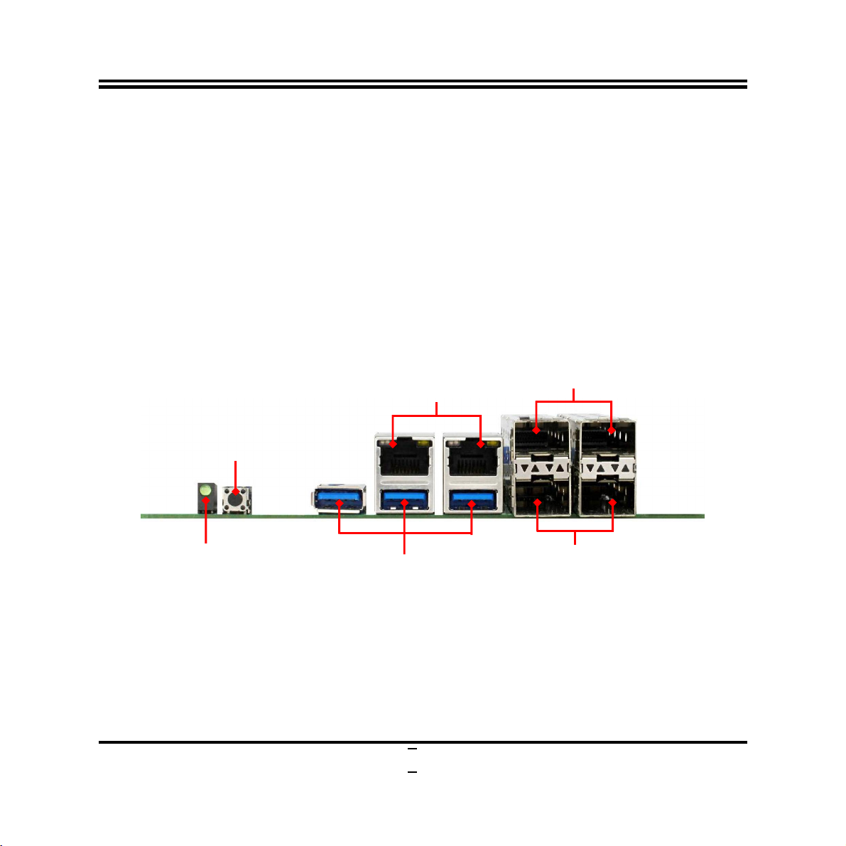
Rear IO Panel Diagram:
Reset Switch
Power LED
RJ-45 LAN Ports
3
SFP+ Ports
SFP+ Ports
Page 9
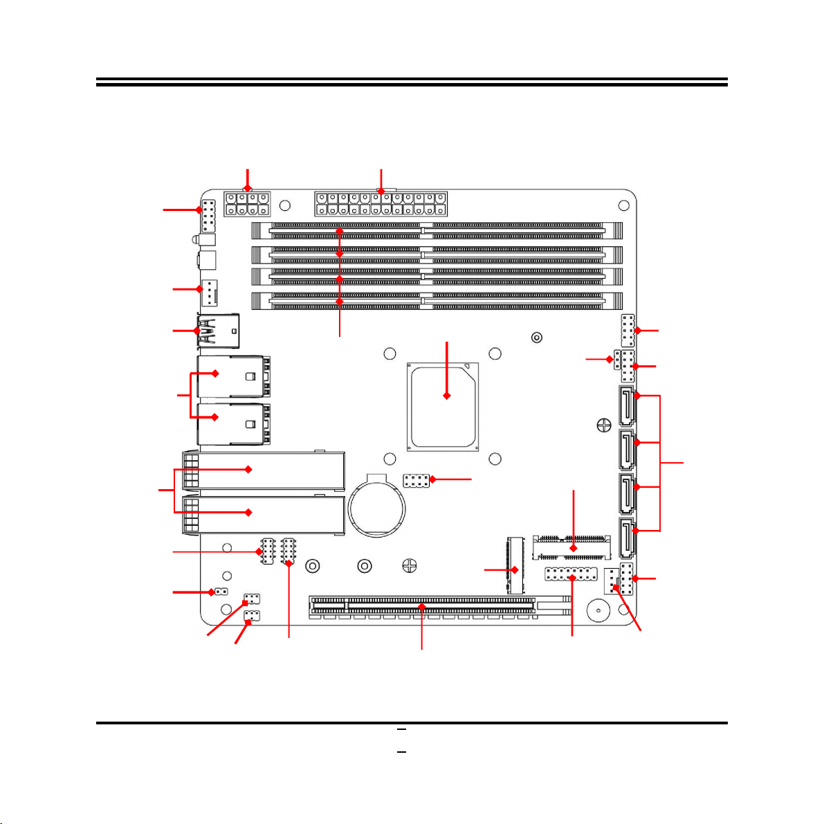
SATAIII Ports
Intel
CPU
Power Connector
Power Connector
C
OM2
Serial Port
USB 2.0 Port
Full-size
PCIE Slot
PCIE x8 Slot
C
OM1
Serial Port
M.2 M Key
Socket 3
Slot
Internal Diagram-Back Side:
ATX 12V
ATX Main
Front Panel
Header
SYSFAN
Connector
USB 3.0 Port
RJ-45 LAN Ports
Over USB 3.0 Ports
SFP+ Ports
Header
COPEN
JP4
DDR4
U-DIMM/R-DIMM
Slot x 4
JBAT
JP3
Header
* JP2: JTAG option, for in-house test purpose only.
JP1
Mini-
(MPE)
VGA Port
Header
*JP2
CPUFAN
Connector
Header
GPIO Port
Header
4
Page 10

Jumper
P/N Function Description
JBAT Pin (1-2): Clear CMOS
Pin (3-4): Clear RTC
Pin (5-6): Flash Override
Pin (7-8): ME Recovery
COPEN Case Open Message Display Select 2-Pin Block
JP1 Power Switch Selection 3-Pin Block
JP3 COM1 Header Pin9 Function Select 4-Pin Block
JP4 COM2 Header Pin9 Function Select 4-Pin Block
Connectors
8-Pin Block
Connector
Name
ATXPWR Main Power Connector
ATX12V CPU Power Connector
CPUFAN CPUFAN Connector
SYSFAN SYSFAN Connector
SATA1/2/3/4 SATAIII Port Connector
USB3 USB 3.0 Port Connector
UL1/UL2 Top: RJ-45 LAN Port Connector
Bottom: USB 3.0 Port Connector
SFP1/ SFP2 Small Form-factor Pluggable Connector
MPE Full-size Mini-PCIE Slot
M2 M.2 Socket 3 Slot
5
Page 11
D
JBAT
Headers
Header Name Description
JW_FP Front Panel Header(PWR LED/ HD
LED/Power Button /Reset)
FP_USB USB 2.0 Port Header 9-pin Block
GPIO GPIO Header 10-pin Block
FP_VGA VGA Port Header 15-pin Block
COM1/COM2 RS232 Serial Port Header 9-pin Block
Chapter 2
Hardware Installation
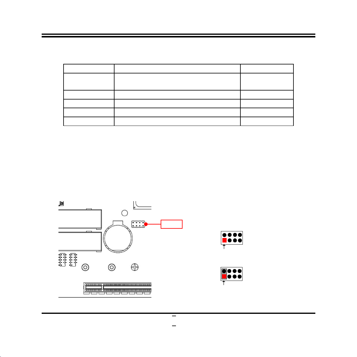
2-1 Jumper Setting
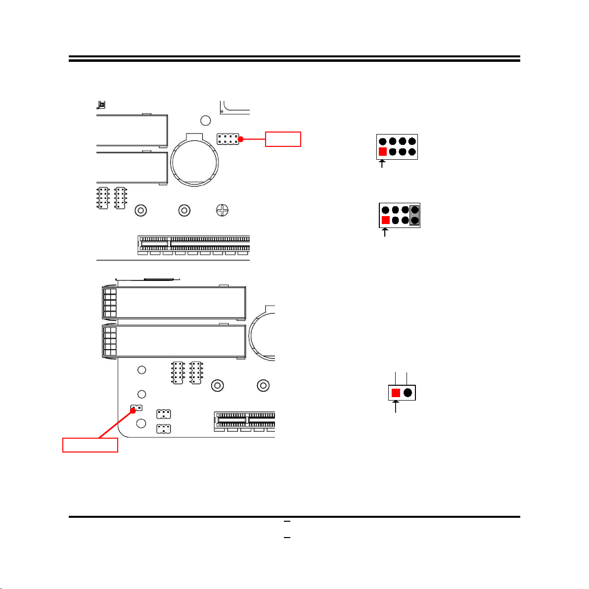
Pin (1-2) of JBAT (8-pin): Clear CMOS RAM Setting
9-pin Block
Pin (1-2) of JBAT→Clear CMOS
1-2 Open: Normal(Default);
1-2 Closed: Clear CMOS(One Touch).
2
Pin1
2
Pin1
6
Page 12
JBAT
JBAT
Pin (3-4) of JBAT (8-pin): RTC Reset
Pin (3-4) of JBAT→RTC Reset
2
Pin1
3-4 Open: Normal(Default);
Pin1
3-4 Closed:RTC Reset.
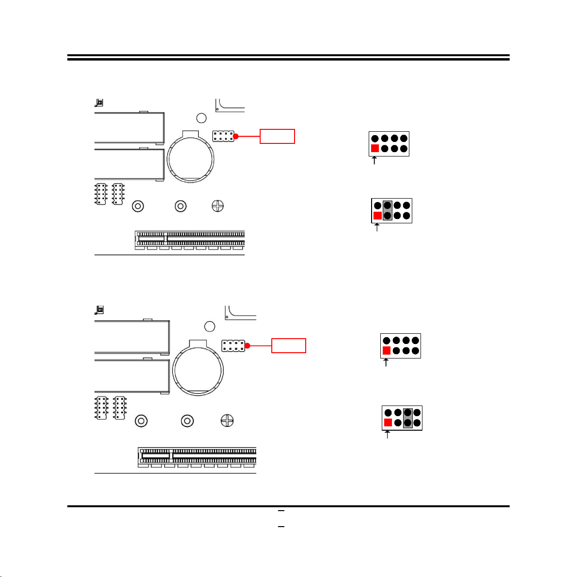
Pin (5-6) of JBAT (8-pin): Flash Override Slect
Pin (5-6) of JBAT→Flash Override
4
3
2
4
3
2
6
4
3
5
Pin1
5-6 Open:Enable Security Measures
in the Flash Descriptor(Default);
2 4
6
3
Pin1
5-6 Closed: Disable Security Measures
in the Flash Descriptor(Override).
5
7
Page 13
Pin1
3
OPEN
GND
JBAT
COPEN
Pin (7-8) of JBAT (8-pin): ME Recovery
Pin (7-8) of JBAT→ME Recovery
2
4
6
5
7-8 Open: Normal(Default);
2
4
6
3
5
Pin1
7-8 Closed:ME Recovery.
COPEN (2-pin): Case Open Message Display Function Select
COPEN→Case Open Detection
CASE
8
7
8
7
Pin1
Pin 1-2 Short
: When Case open function pin short to GND, the Case open function
was detected. When Used, needs to enter BIOS and enable ‘Case Open Detect’
function. In this case if your case is removed, next time when you restart your computer,
a message will be displayed on screen to inform you of this.
8
Page 14
3
4 2
5
JP1
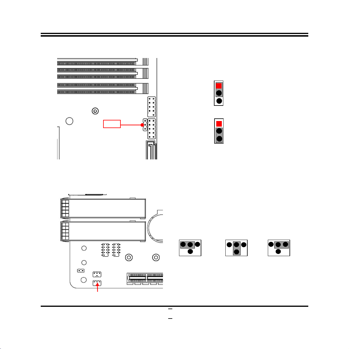
JP1 (3-pin): Power Switch Select
JP1→Power Switch Select
1-2 Closed: VR_ON (AT Mode);
1
1
3
2-3 Closed:Normal (ATX Mode).
* AT Mode Selected: Directly power on as power input ready.
ATX Mode Selected: Press power button to power on after power input ready;
JP3 (4-pin): COM1 Header Pin-9 Function Select
JP3→COM1 Pin-9
6
3 1
2-4 Closed:
RI=RS232;
JP3
9
2
4 6
3
1
5
3-4 Closed:
RI=5V;
2
4 6
1
3
5
4-6 Closed:
RI=12V.
Page 15
4 2
5
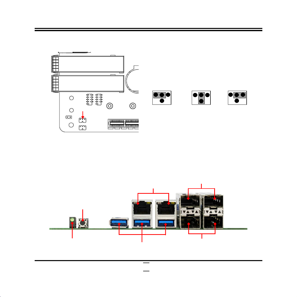
USB 3.0 Ports
JP4 (4-pin): COM2 Header Pin-9 Function Select
JP4→COM2 Pin-9
JP4
2-4 Closed:
RI=RS232;
2-2 Connectors and Headers
2-2-1 Connectors
Rear IO Panel Diagram:
RJ-45 LAN Ports
Reset Switch
2
6
3 1
2
4 6
3
1
5
3-4 Closed:
RI=5V;
SFP+ Ports
4 6
1
3
5
4-6 Closed:
RI=12V.
Power LED
10
SFP+ Ports
Page 16

yboard, mouse or other
devices compatible with USB specification. USB
45 LAN Port
for
R/DAC
Row2
Icon Name Function
Reset Button
Press to
the system.
reset
To connect USB ke
USB 3.0 Port
RJ-
SFP+ Port
3.0 ports supports up to 5Gbps data transfer rate.
This connector is standard RJ-45 LAN jack
Network connection.
Native SFI interface for 10GbE SR/L
SFP+ modules
ATXPWR (24-pin block): Main Power Connector
ATXPWR
Pin12
ROW1 ROW2
PIN
1 +3.3V +3.3V
2 +3.3V -12V
3 GND GND
4 +5V Soft Power on
5 GND GND
6 +5V GND
7 GND GND
8 Power OK NC
9 +5V Stand b y +5V
10 +12V +5V
11 +12V +5V
12 +3.3V GND
Pin1
Row1
11
Page 17

SATA
1 SATA2
SATA3
SATA4
ATX12V (8-pin block): 12V Power Connector
ATX12V
Pin1
Pin Definition No. Definition
GND
1
GND
2
GND
3
GND
4
SATA1/2/3/4 (7-pin Block): SATAIII Port connector
These SATAIII ports that support 6GB/s transfer rate.
4
+12V
5
+12V
6
+12V
7
+12V
8
Pin No. Definition
1 GND
2 TXP
3 TXN
4 GND
5 RXN
6 RXP
7 GND
12
Page 18

+12V Fan Power
+12V Fan Power
CPUFAN
SYSFAN
CPUFAN (4-pin): CPU FAN Connector
Control
Fan Speed
GND
Pin1
SYSFAN (4-pin): System FAN Connector
13
Control
Fan Speed
GND
Pin1
Page 19

* For Dual Channel Memory Installation
DIMMB1
DIMMB2
& DIMMA1
& DIMMA2
Configuration DIMMB1 DIMMB2 DIMMA1 DIMMA2
1 install -- install --
2 -- install -- install
3 install install install install
Notice!
For dual channel installation, you need to install the same brand, speed, size and
type memory module.
It is unable to activate dual channel feature if you install one or three memory
modules, or you install DIMMB1 & DIMMA1 or DIMMB2 & DIMMA2 (DIMM Slot
pair in the same color). Slot order can be from left-to-right or right-to-left, and it
must be installed in pairs.
If you install memory modules in wrong direction, it will damage the motherboard
and memory module.
It will take relatively longer time to start the computer for the first time due to
DRAM detection; larger capacity DRAM will take longer time for detection. It is
also normal for the computer to go through DRAM detection again after system
clear CMOS action, or system memory module changes/relocation.
14
Page 20

VCC
DATA
GND
JW_FP
FP_USB
2-2-2 Headers
JW_FP (9-pin): Front Panel Header
FP_USB (9-pin): USB 2.0 Port Header
HDDLED+
HDDLED-
GND
RSTSW
VCC
Pin 1
2
PWRLED+
PWRLED-
PWRBTN
GND
Pin 1
2
VCC
-
+DATA
-DATA
+DATA
GND
NC
15
Page 21

Pin 1
2
GPIO_
D7
GPIO_
D5
GPIO_
D3
GPIO_
D6
GPIO_
D4
GPIO _
D2
VCC
GND
GREEN
Pin2
RED
NC
GND
GND
GND
A
VSYNC
BLUE
VCC_
+5V
GND
GND
NC
HSYNC
FP_VGA
GPIO (10-pin): GPIO Port Header
FP_VGA (15-pin): VGA Header
GPIO
GPIO_D0
GPIO_D1
Pin1
DCC-DAT
DCC_CLK
16
Page 22

Pin 1
DSR
RTS
RI
DTR
COM
2 COM
1
COM1/COM2 (9-Pin): RS232 Serial Port Header
DCD
SIN
SOUT
GND
6
CTS
17
Page 23

Chapter 3
Introducing BIOS
Notice!
The BIOS options in this manual are for reference only. Different
configurations may lead to difference in BIOS screen and BIOS
screens in manuals are usually the first BIOS version when the board is
released and may be different from your purchased motherboard.
Users are welcome to download the latest BIOS version form our
official website.
The BIOS is a program located on a Flash Memory on the motherboard. This program
is a bridge between motherboard and operating system. When you start the computer,
the BIOS program will gain control. The BIOS first operates an auto-diagnostic test
called POST (power on self test) for all the necessary hardware, it detects the entire
hardware device and configures the parameters of the hardware synchronization.
Only when these tasks are completed done it gives up control of the computer to
operating system (OS). Since the BIOS is the only channel for hardware and software
to communicate, it is the key factor for system stability, and in ensuring that your
system performance as its best.
3-1 Entering Setup
Power on the computer and by pressing <Del> immediately allows you to enter Setup.
If the message disappears before your respond and you still wish to enter Setup,
restart the system to try again by turning it OFF then ON or pressing the “RESET”
button on the system case. You may also restart by simultaneously pressing <Ctrl>,
<Alt> and <Delete> keys. If you do not press the keys at the correct time and the
system does not boot, an error message will be displayed and you will again be asked
to
Press
<Del>
to enter Setup/ Press
<F7>
to enter Popup Menu.
18
Page 24

Menu Items
3-2 BIOS Menu Screen
The following diagram show a general BIOS menu screen:
Menu Bar
General Help Items
Current Setting Value
Function Keys
19
Page 25

3-3 Function Keys
In the above BIOS Setup main menu of, you can see several options. We will explain
these options step by step in the following pages of this chapter, but let us first see a
short description of the function keys you may use here:
Press (left, right) to select screen;
Press (up, down) to choose, in the main menu, the option you want to confirm
or to modify.
Press <Enter> to select.
Press <+>/<–> keys when you want to modify the BIOS parameters for the active
option.
[F1]: General help.
[F2]: Previous value.
[F3]: Optimized defaults.
[F4]: Save & Exit.
Press <Esc> to quit the BIOS Setup.
3-4 Getting Help
Main Menu
The on-line description of the highlighted setup function is displayed at the top right
corner the screen.
Status Page Setup Menu/Option Page Setup Menu
Esc
[F1
] to pop up a small help window that describes the appropriate keys to use
>.
20
Press
and the possible selections for the highlighted item. To exit the Help Window, press
<
Page 26

3-5 Menu Bars
There are several menu bars on top of BIOS screen:
Main To change system basic configuration
Advanced To change system advanced configuration
Intel RC Setup
Chipset To change chipset configuration
Event Logs To change SMBIOS event log settings
Security Password settings
Boot To change boot settings
Save & Exit Save setting, loading and exit options.
User can press the right or left arrow key on the keyboard to switch from menu bar.
The selected one is highlighted.
To change Intel RC setup
21
Page 27

3-6 Main Menu
Main menu screen includes some basic system information. Highlight the item and
then use the <+> or <-> and numerical keyboard keys to select the value you want in
each item.
System Date
Set the date. Please use [Tab] to switch between date elements.
System Time
Set the time. Please use [Tab] to switch between time elements.
22
Page 28

3-7 Advanced Menu
Trusted Computing
Press [Enter] to view current status information , or make settings in ‘
Support
’.
Security Device
Configuration
Security Device Support
Use this item to enable or disable BIOS support for security device. O.S. will not
show Security Device. TCG EFI protocol and INT1A interface will not be available.
The optional settings: [Disabled]; [Enabled].
23
Page 29

*When set as [Enabled], user can make further settings in:
TPM State
Use this item to enable or disable Security Device. Your computer will reboot
during restart in order to change state of the device.
The optional settings: [Disabled]; [Enabled].
*When set as [Enabled], user can make further settings in ‘Pending Operation’:
Pending Operation
Use this item to schedule an operation for the security device. Your computer will
reboot during restart in order to change state of the device.
The optional settings: [None]; [TPM Clear].
► Super I/O Configuration
Press [Enter] to make settings for the following sub-items:
Super IO Configuration
► Serial Port 1 Configuration/ Serial Port 1 Configuration
Press [Enter] to make settings for the following items:
Serial Port 1 Configuration / Serial Port 2 Configuration
Serial Port
Use this item to enable or disable serial port (COM).
The optional settings are: [Disabled]; [Enabled].
Change Settings
Use this item to select an optimal setting for super IO device. Changing setting
may conflict with system resources.
The optional settings are: [Auto]; [IO=3F8h; IRQ=4]; [IO=3F8h;
IRQ=3,4,5,6,7,9,10,11,12]; [IO=2F8h; IRQ=3,4,5,6,7,9,10,11,12]; [IO=3E8h;
IRQ=3,4,5,6,7,9,10,11,12]; [IO=2E8h; IRQ=3,4,5,6,7,9,10,11,12].
ERP Support
The optional settings are: [Disabled]; [Enabled].
This item should be set as [Disabled] if you wish to have all active wake-up
functions.
24
Page 30

Case Open Detect
Use this item to detect case has already open or not, show message in POST.
The optional settings: [Disabled]; [Enabled].
When set as [Enabled], system will detect if COPEN has been short or not (refer to
Page 8); if COPEN is short, system will show Case Open Message during POST.
WatchDog Reset Timer
Use this item to enable or disable WDT reset function. When set as [Enabled], the
following sub-items shall appear:
WatchDog Reset Timer Value
User can select a value in the range of [10] to [255] seconds when ‘WatchDog
Reset Timer Unit’ set as [Sec]; or in the range of [1] to [255] minutes when
‘WatchDog Reset Timer Unit’ set as [Min].
WatchDog Reset Timer Unit
The optional settings are: [Sec.]; [Min.].
► PC Health Status
Press [Enter] to view current hardware health status, or make further settings in
‘SmartFAN Configuration’ and ‘Shutdown Temperature’.
► SmartFAN Configuration
Press [Enter] to make settings for SmartFan Configuration:
SmartFAN Configuration
CPUFAN Smart Mode/SYSFAN Smart Mode
The optional settings are: [Disabled]; [Enabled].
When set as [Enabled], the following sub-items shall appear:
CPUFAN/SYSFAN Full-Speed Temperature
Use this item to set CPUFAN/SYSFAN full speed temperature. Fan will run at full
speed when above this pre-set temperature.
CPUFAN/SYSFAN Full-Speed Duty
Use this item to set CPUFAN/SYSFAN full-speed duty. Fan will run at full speed
when above this pre-set duty.
25
Page 31

CPUFAN/SYSFAN Idle-Speed Temperature
Use this item to set CPUFAN/SYSFAN idle speed temperature. Fan will run at idle
speed when below this pre-set temperature.
CPUFAN/SYSFAN Idle-Speed Duty
Use this item to set CPUFAN/SYSFAN idle speed duty. Fan will run at idle speed
when below this pre-set duty.
Shutdown Temperature
Use this item to select system shutdown temperature.
The optional settings are: [Disabled]; [65oC/149oF]; [70oC/158oF]; [75oC/167oF];
[80oC/176oF]; [85oC/185oF].
Serial Port Console Redirection
COM1
Console Redirection
The optional settings: [Disabled]; [Enabled]. When set as [Enabled], the following
sub-items shall appear:
Console Redirection Settings
The settings specify how the host computer and the remote computer (which the
user is using) will exchange data. Both computers should have the same or
compatible settings.
Press [Enter] to make settings for the following items:
Terminal Type
The optional settings: [VT100]; [VT100+]; [VT-UTF8]; [ANSI].
Emulation: [ANSI]: Extended ASCII char set; [VT100]: ASCII char set; [VT100+]:
Extends VT100 to support color, function keys, etc.; [VT-UTF8]: Uses UTF8
encoding to map Unicode chars onto 1 or more bytes.
Bits per second
Use this item to select serial port transmission speed. The speed must be
matched on the other side. Long or noisy lines may require lower speeds.
The optional settings: [9600]; [19200]; [38400]; [57600]; [115200].
Data Bits
26
Page 32

The optional settings: [7]; [8].
Parity
A parity bit can be sent with the data bits to detect some transmission errors.
The optional settings: [None]; [Even]; [Odd]; [Mark]; [Space].
[Even]: parity bit is 0 if the num of 1’s in the data bits is even; [Odd]: parity bit is 0
if num of 1’s in the data bits is odd; [Mark]: parity bit is always 1; [Space]: Parity
bit is always 0; [Mark] and [Space] Parity do not allow for error detection.
Stop Bits
Stop bits indicate the end of a serial data packet. (A start bit indicates the
beginning). The standard setting is 1 stop bit. Communication with slow devices
may require more than 1 stop bit.
The optional settings: [1]; [2].
Flow Control
Flow control can prevent data loss from buffer overflow. When sending data, if
the receiving buffers are full, a “stop” signal can be sent to stop the data flow.
Once the buffers are empty, a “start” signal can be sent to re-start the flow.
Hardware flow control uses two wires to send start/stop signals.
The optional settings: [None]; [Hardware RTS/CTS].
VT-UTF8 Combo Key Support
Use this item to enable VT-UTF8 Combination Key Support for ANSI/VT100
terminals.
The optional settings: [Disabled]; [Enabled].
Recorder Mode
With this mode enable only text will be sent. This is to capture Terminal data.
The optional settings: [Disabled]; [Enabled].
Resolution 100x31
Use this item to enable or disable extended terminal resolution.
The optional settings: [Disabled]; [Enabled].
Putty KeyPad
Use this item to select FunctionKey and KeyPad on Putty.
The optional settings: [VT100]; [Linux]; [XTERMR6]; [SCO]; [ESCN]; [VT400].
27
Page 33

Legacy Console Redirection
Legacy Console Redirection Settings
Press [Enter] to make settings for the following items:
Redirection COM Port
Use this item to select a COM port to display redirection of Legacy OS and
Legacy OPROM Messages.
The default setting is: [COM1].
Resolution
On Legacy OS, the Number of Rows and Columns supported redirection.
The optional settings: [80x24]; [80x25].
Redirection After BIOS POST
The optional settings are: [Always Enable]; [BootLoader].
Whet [Bootloader] is selected, then Lagacy Console Redirection is disabled
before booting to legacy OS. When [Always Enable] is selected, then Legacy
Console is enabled for legacy OS. Default setting for this option is set to [Always
Enable].
Serial Port for Out-of-Band Management/
Windows Emergency Management Services (EMS)
Console Redirection
The optional settings: [Disabled]; [Enabled]. When set as [Enabled], the following
sub-items shall appear:
Console Redirection Settings
The settings specify how the host computer and the remote computer (which the
user is using) will exchange data. Both computers should have the same or
compatible settings.
Press [Enter] to make settings for the following items:
Out-of-Band Mgmt Port
The optional setting is: [COM1].
Terminal Type
The optional settings: [VT100]; [VT100+]; [VT-UTF8]; [ANSI].
28
Page 34

[VT-UTF8] is the preferred terminal type for out-of-band management. The next
best choice is [VT100+] and them [VT100]. See above, in Console Redirection
Settings page, for more help with Terminal Type/Emulation.
Bits per second
Use this item to select serial port transmission speed. The speed must be
matched on the other side. Long or noisy lines may require lower speeds.
The optional settings: [9600]; [19200]; [57600]; [115200].
Flow Control
Flow control can prevent data loss from buffer overflow. When sending data, if
the receiving buffers are full, a “stop” signal can be sent to stop the data flow.
Once the buffers are empty, a “start” signal can be sent to re-start the flow.
Hardware flow control uses two wires to send start/stop signals.
The optional settings: [None]; [Hardware RTS/CTS]; [Software Xon/Xoff].
Data Bits
The default setting is: [8].
*This item may or may not show up, depending on different configuration.
Parity
The default setting is: [None].
*This item may or may not show up, depending on different configuration.
Stop Bits
The default setting is: [1].
*This item may or may not show up, depending on different configuration.
Network Stack Configuration
Press [Enter] to go to ‘Network Stack’ screen to make further settings.
Network Stack
The optional settings are: [Enabled]; [Disabled].
When set as [Enabled], the following sub-items shall appear:
Ipv4 PXE Support
The optional settings are: [Disabled]; [Enabled].
Use this item to enable Ipv4 PXE Boot Support. When set as [Disabled], Ipv4 PXE
boot option will not be created.
29
Page 35

Ipv4 HTTP Support
The optional settings are: [Disabled]; [Enabled].
Use this item to enable Ipv4 HTTP Boot Support. When set as [Disabled], Ipv4
HTTP boot option will not be created.
Ipv6 PXE Support
The optional settings are: [Disabled]; [Enabled].
Use this item to enable Ipv6 PXE Boot Support. When set as [Disabled], Ipv6 PXE
boot option will not be created.
Ipv6 HTTP Support
The optional settings are: [Disabled]; [Enabled].
Use this item to enable Ipv6 HTTP Boot Support. When set as [Disabled], Ipv6
HTTP boot option will not be created.
PXE Boot Wait Time
Use this item to set wait time to press [ESC] key to abort the PXE boot.
Media Detect Count
Use this item to set number of times presence of media will be checked.
The optional settings range from [1] to [50].
CSM Configuration
Press [Enter] to make settings for the following sub-items:
Compatibility Support Module Configuraton
Boot option filter
This item controls Legacy/UEFI ROMs priority.
The optional settings are: [UEFI and Legacy]; [Legacy only]; [UEFI only].
Network
This item controls the execution of UEFI and Legacy PXE OpROM.
The optional settings are: [Do not launch]; [UEFI]; [Legacy].
Storage
This item controls the execution of UEFI and Legacy Storage OpROM.
The optional settings are: [Do not launch]; [UEFI]; [Legacy].
Video
This item controls the execution of UEFI and Legacy Video OpROM.
30
Page 36

The optional settings are: [UEFI]; [Legacy].
Other PCI devices
This item determines OpROM execution policy for devices other than Network,
storage or video.
The optional settings are: [Do not launch]; [UEFI]; [Legacy].
► Wake-up Function Settings
Press [Enter] to make settings for the following sub-items:
Wake-up System with Fixed Time
Use this item to enable or disable system wake on RTC alarm event.
The optional settings: [Disabled]; [Enabled].
When set as [Enabled], system will wake on the hour/min/sec specified.
Wake-up System with Dynamic Time
Use this item to enable or disable system wake on RTC alarm event.
System will wake on the current time + Increase minutes.
The optional settings: [Disabled]; [Enabled].
When set as [Enabled], system will wake on the current time + increased
minute(s).
USB Power Gating in S5
Use this item to enable or disable USB power gating in S5.
The optional settings: [Disabled]; [Enabled].
**Note: This function is supported when ‘ERP Support’ is set as [Disabled].
USB Configuration
Press [Enter] to make settings for the following sub-items:
USB Configuration
Legacy USB Support
The optional settings are: [Enabled]; [Disabled]; [Auto].
[Enabled]: To enable legacy USB support.
[Disabled]: To keep USB devices available only for EFI specification,
[Auto]: To disable legacy support if no USB devices are connected.
XHCI Hand-off
This is a workaround for OSes without XHCI hand-off support. The XHCI
31
Page 37

ownership change should be claimed by XHCI driver.
The optional settings are: [Enabled]; [Disabled].
USB Mass Storage Driver Support
The optional settings are: [Disabled]; [Enabled].
Port 60/64 Emulation
Use item to enable I/O port 60h/64h emulation support. This should be enabled for
the complete USB keyboard legacy support for the non-USB aware OSes.
The optional settings are: [Disabled]; [Enabled].
USB Hardware Delays and Time-outs:
USB Transfer Time-out
Use this item to set the time-out value for control, bulk, and interrupt transfers.
The optional settings are: [1 sec]; [5 sec]; [10 sec]; [20 sec].
Device Reset Time-out
Use this item to set USB mass storage device start unit command time-out.
The optional settings are: [10 sec]; [20 sec]; [30 sec]; [40 sec].
Device Power-up Delay
Use this item to set maximum time the device will take before it properly reports
itself to the host controller.
The optional settings: [Auto]; [Manual].
‘Auto’ uses default value: for a root port it is 100 ms, for a hub port the delay is
taken from hub descriptor.
Select [Manual] you can set value for the following sub-item: ‘Device Power-up
Delay in Seconds’.
Device Power-up Delay in Seconds
The delay range is from [1] to [40] seconds, in one second increments.
► Intel (R) I210 Gigabit Network Connection (XX:XX:XX:XX:XX:XX)/…
These items show current RJ-45 network brief information.
► Intel (R) Ethernet Connection X553 10 GbE SFP+ (XX:XX:XX:XX:XX:XX)/…
These items show current SPF+ network brief information.
32
Page 38

3-8 Intel RC Setup Menu
► Processor Configuration
Press [Enter] to view current CPU configuration and make settings for the following
sub-items:
EIST(GV3)
Use this item to enable or disable EIST. GV3 and TM1 must be enabled fro TM2 to
be available.
GV3 must be set as [Enabled] for ‘Turbo’ item. When set as [Disabled], user can
not make further settings in ‘Turbo’ and ‘Enhanced Halt State (C1E)’:
33
Page 39

Turbo
Use this item to enable or disable CPU Turbo capability. This option only applies to
ES2 and above.
The optional settings: [Disabled]; [Enabled].
CPU C-States
This item is for user to enable the enhanced Cx state of the CPU. This will take
effect after reboot.
The optional settings: [Disabled]; [Enabled].
When set as [Enabled], user can make further settings in the following items:
Package C State Limit
Use this item to enable or disable package C State limit.
The optional settings: [No Pkg C-State]; [No S0Ix]; [No Limit].
Max Core C-State
The optional settings: [C1]; [C6].
Enhanced Halt State (C1E)
Use this item to enable the enhanced C1E state of the CPU. This will tale effect
after reboot.
The optional settings: [Disabled]; [Enabled].
Monitor/Mwait
Use this item to enable or disable the Monitor/Mwait instruction.
The optional settings: [Disabled]; [Enabled].
Machine Check
Use this item to enable or disable the Machine Check.
The optional settings: [Disabled]; [Enabled].
Max CPUID Value Limit
The optional settings: [Disabled]; [Enabled].
This should be enabled in order to boot legacy OSes that cannot support CPUs
with extended CPUID functions.
Execute Disable Bit
The optional settings: [Disabled]; [Enabled].
When disabled, forces the XD feature flag to always return 0.
34
Page 40

VMX
The optional settings: [Disabled]; [Enabled].
Use this item to enable or disable Vanderpool Technology. This will take effects
after reboot.
Dump Crash Log
Use this item to enable or disable ‘Dump Crash Log’ function.
The optional settings: [Enabled]; [Disabled].
► Server ME Configuration
Press [Enter] to view current general ME configuration.
► South Bridge Chipset Configuration
Press [Enter] to make further settings in South Bridge Parameters.
SATA Configuration
Press [Enter] to make settings for SATA controller configuration, or view current
available SATA device configuration.
Enable SATA 0/ Enable SATA 1
Use this item to enable or disable SATA controller if supported by current CPU
SKU.
The optional settings: [Disabled]; [Enabled].
35
Page 41

3-9 Event Logs Menu
► Change Smbios Event Log Settings
Press [Enter] to change the Smbios Event Log Configuration:
Enabling/Disabling Option
Smbios Event Log
Use this item to enable or disable all features of Smbios Event logging during boot.
The optional settings: [Disabled]; [Enabled].
*When set as [Enabled], user can make further settings in:
Erasing Settings
36
Page 42

Erase Event Log
Use this item to choose options for erasing Smbios Event Log. Erasing is done
prior to any logging activation during reset.
The optional settings: [No]; [Yes, Next reset]; [Yes, Every Reset].
When Log is Full
Use this item to choose options for reactions to a full Smbios Event Log.
The optional settings: [Do Nothing]; [Erase Immediately].
Smbios Event Log Standard Settings
Log System Boot Event
Use this item to choose options to enable or disable logging of system boot event.
The optional settings: [Enabled]; [Disabled].
MECI
Multiple Event Count Increment: The number of occurrences of a duplicate event
that must pass before the multiple-event counter of log entry is updated. The value
ranges from 1 to 255.
METW
Multiple Event Time Window: The number of minutes which pass between
duplicate log entries which utilize a multiple-event counter. The value ranges from
0 to 99 minutes.
Custom Options
Log OEM Codes
Use this item to choose options to enable or disable logging of EFI Status Codes
as OEM Codes (if not already converted to legacy).
The optional settings: [Enabled]; [Disabled].
*When set as [Enabled], user can make further settings in:
Convert OEM Codes
Use this item to enable or disable the converting of EFI Status Codes to Standard
Smbios Types (Not all may be translated).
The optional settings: [Enabled]; [Disabled].
► View Smbios Event Log
Press [Enter] to view Date, Time, Error Code and Severity of Smbios Event Log
37
Page 43

Records.
3-10 Security Menu
Security menu allow users to change administrator password and user password
settings.
Administrator Password
If there is no password present on system, please press [Enter] to create new
administrator password. If password is present on system, please press [Enter] to
verify old password then to clear/change password. Press again to confirm the new
38
Page 44

administrator password.
User Password
If there is no password present on system, please press [Enter] to create new
administrator password. If password is present on system, please press [Enter] to
verify old password then to clear/change password. Press again to confirm the new
administrator password.
Secure Boot
Press [Enter] to make customized secure settings:
Enable Secure Boot
The optional settings are: [Disabled]; [Enabled].
Secure Boot activated when Platform Key (PK) is enrolled, system mode is
User/Deployed, and CSM function is disabled.
Secure Boot Mode
The optional settings are: [Standard]; [Custom].
Set UEFI Secure Boot Mode to Standard mode or Custom mode.
In Custom mode Secure Boot Variables can be configured without authentication.
This change is effective after save. After reset, this mode will return to Standard
mode.
* When set as [Standard], user can only apply default settings and can not make
further settings in ‘Reset to Setup Mode’, ‘Restore Factory Keys’ and
‘Key Management’;
When set as [Custom], user can make further settings in ‘Reset to Setup Mode’,
‘Restore Factory Keys’ and ‘Key Management’:
Reset to Setup Mode
Use this item to force system to setup mode-delete all Secure Boot Key
databases.
Restore Factory Keys
Use this item to force system to user mode-restore factory default Secure Boot
Key databases.
Key Management
This item enables experienced users to modify Secure Boot variables without full
39
Page 45

authentication, witch includes the following items:
Provision Factory Default Keys
This item is for user to install factory default secure boot keys when system is in
Setup Mode.
Restore Factory Keys
This item forces system to User Mode-restore factory default secure boot key
databases.
Enroll Efi Image
This item allows the image to run in Secure Boot mode. Enroll SHA256 hash of
the binary into Authorized Signature Database (db).
Save all Secure Boot Variables
This item will save NRRAM content of all Secure Boot variables to the files
(WFI_SIGNATURE_LIST data format) in root folder on a target file system
device.
Platform Key (PK)/Key Exchange Keys/Authorized Signature/Forbidden
Signature/ Authorized TimeStamps/OS Recovery Signatures
Use this item to enroll Factory Defaults or load the keys from a file with:
1. Public Key Certificate in:
a) EFI_SIGNATURE_LIST
b) EFI_ CERT_X509 (DER encoded)
c) EFI_ CERT_RSA2048 (bin)
d) EFI_ CERT_SHA256 (bin)
2. Authenticated UEFI Variable
3. EFI PE/COFF Image (SHA256)
Key source: Default, External, Mixed, Test.
40
Page 46

3-11 Boot Menu
Setup Prompt Timeout
Use this item to set number of seconds to wait for setup activation key.
Bootup Numlock State
Use this item to select keyboard numlock state.
The optional settings are: [On]; [Off].
Quiet Boot
The optional settings are: [Disabled]; [Enabled].
Boot Option Priorities
41
Page 47

Boot Option #1/ Boot Option #2…
Use this item to decide system boot order from available options.
HDD BootSector Write
Use this item to enable or disable writes to Hard Disk Sector 0.
The optional settings are: [Normal]; [Write Protect].
3-12 Save & Exit Menu
42
Page 48

Save Changes and Reset
This item allows user to reset the system after saving the changes.
Discard Changes and Reset
This item allows user to reset the system without saving any changes.
Restore Defaults
Use this item to restore /load default values for all the setup options.
Save as User Defaults
Use this item to save the changes done so far as user defaults.
Restore User Defaults
Use this item to restore the User Defaults to all the setup options.
Boot Override
The available options here are dynamically updated and make system boot to any
boot option selected.
43
 Loading...