

Page 1

Intel® Server Board S1200KP
Product Guide
Order Number: G39481-003
Page 2

Disclaimer
Disclaimer
Information in this document is provided in connection with Intel® products. No license, express or implied, by estoppel or
otherwise, to any intellectual property rights is granted by this document. Except as provided in Intel
Conditions of Sale for such products, Intel® assumes no liability whatsoever, and Intel® disclaims any express or implied
warranty, relating to sale and/or use of Intel® products including liability or warranties relating to fitness for a particular
purpose, merchantability, or infringement of any patent, copyright or other intellectual property right. Intel® products are not
intended for use in medical, life saving, or life sustaining applications. Intel® may make changes to specifications and product
descriptions at any time, without notice.
Intel® Server Board S1200KP may contain design defects or errors known as errata which may cause the product to deviate
from published specifications. Current characterized errata are available on request.
Contact your local Intel® sales office or your distributor to obtain the latest specifications and before placing your
product order.
Copies of documents which have an ordering number and are referenced in this document, or other Intel® literature, may be
obtained from Intel Corporation by going to the World Wide Web site at: http://www.intel.com/ or by calling 1-800-548-4725.
Intel, Intel Core, and Pentium are trademarks of Intel Corporation in the United States and other countries.
®
’s Terms and
* Other names and brands may be claimed as the property of others.
Copyright © 2012, Intel Corporation. All rights reserved.
ii Intel® Server Board S1200KP Product Guide
Page 3
Preface
Term
Description
GB
Gigabyte (1,073,741,824 bytes)
GHz
Gigahertz (one billion hertz)
KB
Kilobyte (1024 bytes)
This Product Guide gives information about board layout, component installation, BIOS update,
and regulatory requirements for Intel® Server Board S1200KP.
Intended Audience
The Product Guide is intended for technically qualified personnel. It is not intended for
general audiences.
Use Only for Intended Applications
All Intel® Server Boards are evaluated as Information Technology Equipment (I.T.E.) for use in
personal computers (PC) for installation in homes, offices, schools, computer rooms, and similar
locations. The suitability of this product for other PC or embedded non-PC applications or other
environments, such as medical, industrial, alarm systems, test equipment, etc. may not be supported
without further evaluation by Intel®.
Preface
Document Organization
The chapters in this Product Guide are arranged as follows:
1 Server Board Features: a summary of product features
2 Installing and Replacing Server Board Components: instructions on how to install the Server
Board and other hardware components
3 Updating the BIOS: instructions on how to update the BIOS
a. Error Messages and Indicators: information about BIOS error messages and beep codes
Conventions
The following conventions are used in this manual:
CAUTION
Cautions warn the user about how to prevent damage to hardware or loss
of data.
NOTE
Notes call attention to important information.
Terminology
The table below gives descriptions of some common terms used in the product guide.
Intel® Server Board S1200KP Product Guide iii
Page 4

Preface
Term
Description
MB
Megabyte (1,048,576 bytes)
Mb
Megabit (1,048,576 bits)
MHz
Megahertz (one million hertz)
iv Intel® Server Board S1200KP Product Guide
Page 5

Contents
Contents
Preface ...................................................................................................................................... iii
Intended Audience ................................ .............................................................. iii
Use Only for Intended Applications ..................................................................... iii
Document Organization ...................................................................................... iii
Conventions ........................................................................................................ iii
Terminology ........................................................................................................ iii
1 Server Board Features ........................................................................................................ 1
Supported Operating Systems .............................................................................................. 3
Server Board Components .................................................................................................... 4
Processor .............................................................................................................................. 6
Intel® C206 Express Chipset .................................................................................................. 7
Main Memory ........................................................................................................................ 7
Graphics Subsystem ............................................................................................................. 8
Integrated Graphics ...................................................................................................... 8
Intel® HD Graphics ............................................................................................... 8
Digital Visual Interface (DVI-I) .............................................................................. 8
VGA Displays ....................................................................................................... 8
PCI Express* x16 Graphics .......................................................................................... 8
LAN Subsystem .................................................................................................................. 10
USB Support ....................................................................................................................... 10
SATA Support ..................................................................................................................... 10
Expandability ....................................................................................................................... 11
Legacy I/O ........................................................................................................................... 11
BIOS ................................................................................................................................... 11
SATA Auto Configuration............................................................................................ 11
PCI*/PCI Express* Auto Configuration........................................................................ 11
Security Passwords .................................................................................................... 11
Hardware Management ....................................................................................................... 12
Hardware Monitoring and Fan Speed Control ............................................................. 13
Fan Monitoring ........................................................................................................... 13
Chassis Intrusion ........................................................................................................ 13
Power Management ............................................................................................................ 13
Software Support ........................................................................................................ 13
ACPI .................................................................................................................. 13
Hardware Support ...................................................................................................... 14
Power Connectors ............................................................................................. 14
Fan Headers ...................................................................................................... 14
LAN Wake Capabilities ...................................................................................... 14
Instantly Available PC Technology ..................................................................... 15
+5 V Standby Power Indicator LED .................................................................... 15
Wake from USB ................................................................................................. 17
PCI Express* WAKE# Signal Wake-up Support ................................ ................. 17
Speaker ............................................................................................................................... 17
Real-Time Clock Subsystem ............................................................................................... 17
Intel® Server Board S1200KP Product Guide v
Page 6

Contents
2 Installing and Replacing Server Board Components...................................................... 18
Before You Begin ................................................................................................................ 18
Installation Precautions ....................................................................................................... 19
Prevent Power Supply Overload ................................................................................. 19
Observe Safety and Regulatory Requirements ........................................................... 19
Installing the I/O Shield ....................................................................................................... 20
Installing and Removing the Server Board .......................................................................... 21
Installing and Removing a Processor .................................................................................. 22
Installing a Processor ................................................................................................. 22
Installing a Processor Fan Heat Sink .......................................................................... 26
Connecting the Processor Fan Heat Sink Cable ......................................................... 26
Removing the Processor ............................................................................................ 26
Installing and Removing System Memory ............................................................................ 27
Installing DIMMs ......................................................................................................... 28
Removing DIMMs ....................................................................................................... 30
Installing and Removing PCI Express* x16 Graphics Cards ................................................ 30
Installing a PCI Express* x16 Graphics Card .............................................................. 30
Removing a PCI Express* x16 Graphics Card ............................................................ 32
Connecting SATA Drives ..................................................................................................... 33
Connecting to the Internal Headers ..................................................................................... 34
Chassis Intrusion Header ........................................................................................... 34
Front Panel USB 2.0 Headers .................................................................................... 35
Front Panel Header .................................................................................................... 35
Alternate Front Panel Power LED Header .................................................................. 35
Low Pin Count (LPC) Debug header .......................................................................... 36
Connecting Chassis Fan and Power Supply Cables ............................................................ 37
Connecting a Chassis Fan .......................................................................................... 37
Connecting Power Supply Cables .............................................................................. 38
Setting the BIOS Configuration Jumper ............................................................................... 39
Clearing Passwords ............................................................................................................ 40
Replacing the Battery .......................................................................................................... 41
3 Updating the BIOS............................................................................................................. 43
Updating the BIOS with the Intel® Flash Memory Update Utility ........................................... 43
Obtaining the BIOS Update File.................................................................................. 43
Updating the BIOS with the Intel® Flash Memory Update Utility .................................. 43
Updating the BIOS Using the F7 Function Key .................................................................... 45
Recovering the BIOS .................................................................................................. 45
Appendix A: Error Messages and Indicators ................................................................ 46
BIOS Error Codes ............................................................................................................... 46
BIOS Error Messages ......................................................................................................... 47
vi Intel® Server Board S1200KP Product Guide
Page 7

Figures
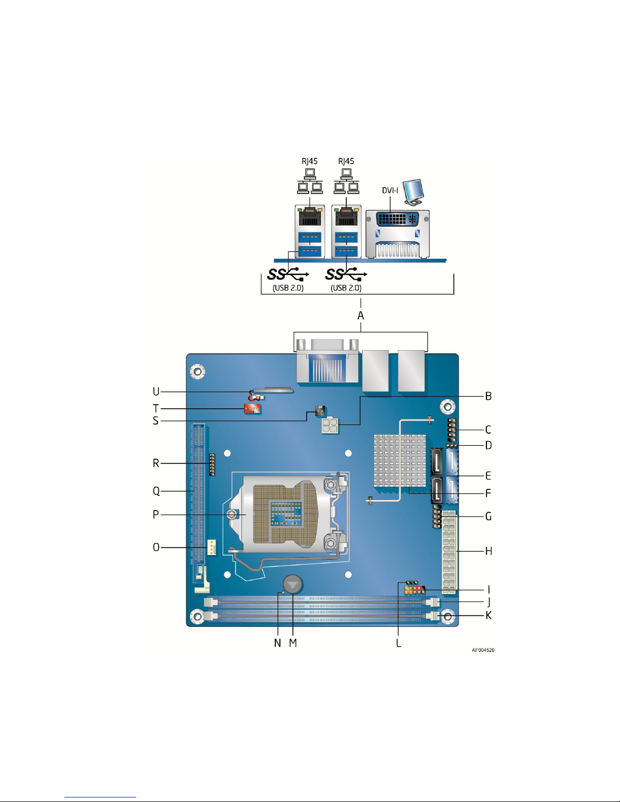
Figure 1. Intel® Server Board S1200KP Components ............................................................ 4
Figure 2. LAN Connector LEDs ........................................................................................... 10
Figure 3. Location of the Standby Power Indicator .............................................................. 16
Figure 4. Installing the I/O Shield......................................................................................... 20
Figure 5. Intel® Server Board S1200KP Mounting Screw Hole Locations ............................. 21
Figure 6. Unlatch the Socket Lever ..................................................................................... 22
Figure 7. Lift the Load Plate ................................................................................................ 23
Figure 8. Remove the Processor from the Protective Cover ................................................ 24
Figure 9. Install the Processor ............................................................................................. 24
Figure 10. Secure the Load Plate in Place .......................................................................... 25
Figure 11. Connecting the Processor Fan Heat Sink Power Cable to the Processor Fan
Header .......................................................................................................................... 26
Figure 12. Dual Channel Memory Configuration Example ................................................... 27
Figure 13. Use DDR3 DIMMs .............................................................................................. 28
Figure 14. Installing a DIMM ................................................................................................ 29
Figure 15. Installing a PCI Express* x16 Graphics Card ...................................................... 31
Figure 16. Removing a PCI Express* x16 Graphics Card .................................................... 32
Figure 17. Connecting a SATA Drive ................................................................................... 33
Figure 18. Internal Headers ................................................................................................. 34
Figure 19. Location of the Chassis Fan Header ................................................................... 37
Figure 20. Connecting Power Supply Cables ...................................................................... 38
Figure 21. Location of the BIOS Configuration Jumper Block .............................................. 39
Figure 22. Removing the Battery ......................................................................................... 42
Figures
Intel® Server Board S1200KP Product Guide vii
Page 8

Tables
Tables
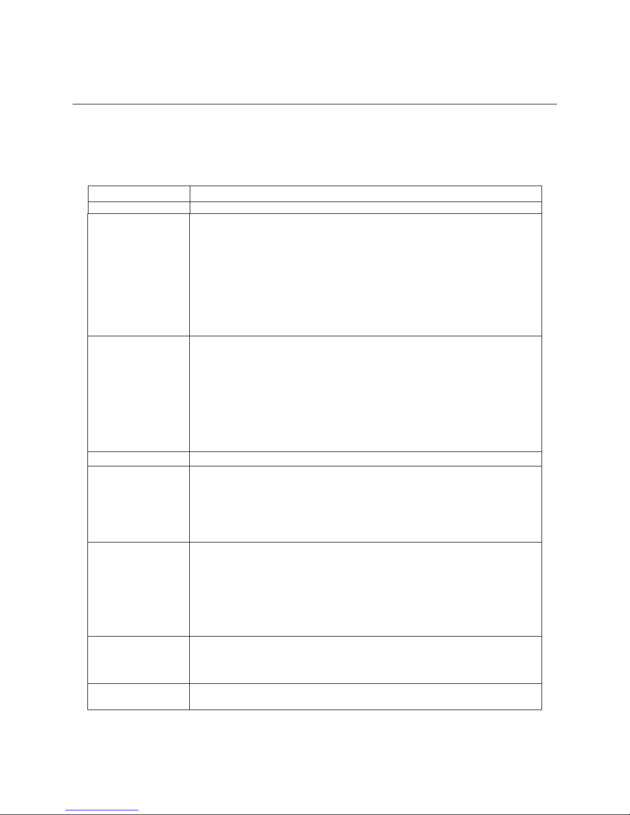
Table 1. Feature Summary .................................................................................................... 1
Table 2. Intel® Server Board S1200KP Components ............................................................. 5
Table 3. LAN Connector LEDs ............................................................................................ 10
Table 4. Chassis Intrusion Header Signal Names ............................................................... 34
Table 5. USB 2.0 Header Signal Names ............................................................................. 35
Table 6. Front Panel Header Signal Names ........................................................................ 35
Table 7. Alternate Front Panel Power LED Header Signal Names ...................................... 35
Table 8. LPC Debug Header ............................................................................................... 36
Table 9. Jumper Settings for the BIOS Setup Program Modes ............................................ 40
Table 10. BIOS Beep Codes ............................................................................................... 46
Table 11. Front-panel Power LED Blink Codes ................................................................... 46
Table 12. BIOS Error Messages .......................................................................................... 47
viii Intel® Server Board S1200KP Product Guide
Page 9

Tables
<This page is intentionally left blank.>
Intel® Server Board S1200KP Product Guide ix
Page 10
Server Board Features
Feature
Description
Form Factor
Mini-ITX (6.7 inches by 6.7 inches [170.18 millimeters by 170.18 millimeters])
Processor
Intel® Xeon® E3-1200 Processors, the 2nd Generation Intel® Core™ i3
Processors, Intel® Xeon® E3-1200 V2 Processors or the 3rd Generation Intel®
Core™ i3 Processors with up to 95W TDP in an LGA1155 socket
1, 2
― One PCI Express* 2.0 x16 (with Intel® Xeon® E3-1200 Processors or the 2nd
Generation Intel® Core™ i3 Processors) or PCI Express* 3.0 x 16 (with
Intel® Xeon® E3-1200 V2 Processors or the 3rd Generation Intel® Core™ i3
Processors) graphics interface
― Integrated memory controller with dual channel DDR3 memory support
― Integrated graphics processing (processors with Intel® Graphics
Technology)
Memory
Two 240-pin DDR3 DRAM Dual Inline Memory Module (DIMM) sockets
Support for DDR3 1066/1333 MHz (with Intel® Xeon® E3-1200 Processors or the
2nd Generation Intel® Core™ i3 Processors) or DDR3 1333/1600 MHz (with Intel®
Xeon® E3-1200 V2 Processors or the 3rd Generation Intel® Core™ i3 Processors)
DIMMs
Support for 1Gb, 2Gb, and 4Gb memory technology
Support for up to 16 GB of system memory with two DIMMs using 4 Gb memory
technology
Support for ECC and non-ECC memory3
Chipset
Intel® C206 Platform Controller Hub (PCH) Chipset
Graphics
Integrated graphics support for processors with Intel® Graphics Technology:
― DVI-I
Discrete graphics support for PCI Express* 2.0 x16 (with Intel® Xeon® E3-1200
Processors or the 2nd Generation Intel® Core™ i3 Processors) or PCI Express*
3.0 x 16 (with Intel® Xeon® E3-1200 V2 Processors or the 3rd Generation Intel®
Core™ i3 Processors) add-in graphics card
Peripheral Interfaces
Eight USB 2.0 ports:
― Four ports are implemented with stacked back panel connectors (black)
― Four front panel ports implemented through three internal headers
Two SATA 6.0Gb/s interfaces through Intel® C206 Chipset with Intel® Rapid
Storage Technology RAID support (blue)
Two SATA 3.0Gb/s interfaces through Intel® C206 Chipset with Intel® Rapid
Storage Technology RAID support (black)
Expansion
Capabilities
One PCI Express* 2.0 x16 (with Intel® Xeon® E3-1200 Processors or the 2nd
Generation Intel® Core™ i3 Processors) or PCI Express* 3.0 x 16 (with Intel®
Xeon® E3-1200 V2 Processors or the 3rd Generation Intel® Core™ i3 Processors)
add-in card connector
BIOS
Intel® BIOS resident in the Serial Peripheral Interface (SPI) Flash device
Support for Advanced Configuration and Power Interface (ACPI), Plug and Play,
1 Server Board Features
This chapter briefly describes the features of Intel® Server Board S1200KP. Table 1 summarizes the
major features of the Server Board.
Table 1. Feature Summary
Intel® Server Board S1200KP Product Guide 1
Page 11
Server Board Features
Feature
Description
and System Management BIOS (SMBIOS)
Instantly Available PC
Technology
Support for PCI Express* Revision 2.0 (with Intel® Xeon® E3-1200 Processors or
the 2nd Generation Intel® Core™ i3 Processors) or PCI Express* Revision 3.0
(with Intel® Xeon® E3-1200 V2 Processors or the 3rd Generation Intel® Core™ i3
Processors)
Suspend to RAM support
Wake on PCI Express*, LAN, front panel, and USB ports
LAN Support
Gigabit (10/100/1000Mbits/s) LAN subsystem using the Intel
®
82574 and 82579
Gigabit Ethernet Controller
Legacy I/O Control
Nuvoton* W83677HG-i I/O controller for hardware management support
Hardware Monitor
Subsystem
Hardware monitoring through the Nuvoton* I/O controller
Voltage sense to detect out of range power supply voltages
Thermal sense to detect out of range thermal values
Two fan headers
Two fan sense inputs used to monitor fan activity
Fan speed control
Notes:
1. Pairing a mini-ITX chassis and more than 65W TDP processor with the supplied standard Intel
solution may not meet Intel®’s thermal requirement standard. Please verify that your thermal solution and
chassis will meet the necessary thermal requirements. Failing to do so may cause the processor to throttle,
significantly decreasing system performance.
2. The product codes of DBS1200KP and BBS1200KP can only support Intel
®
Xeon® E3-1200 Processors or the
2nd Generation Intel® Core™ i3 Processors. The product codes of DBS1200KPR and BBS1200KPR can
support Intel® Xeon® E3-1200 Processors, the 2nd Generation Intel® Core™ i3 Processors, Intel® Xeon® E3-1200
V2 Processors or the 3rd Generation Intel® Core™ i3 Processors.
3. ECC DIMMS are recommended to use for server system.
®
thermal
2 Intel® Server Board S1200KP Product Guide
Page 12

Supported Operating Systems
The Server Board provides full support for the following operating systems:
Microsoft Windows 7* Ultimate 64-bit edition
Microsoft Windows 7* Ultimate 32-bit edition
Microsoft Windows 7* Home Basic 64-bit edition
Microsoft Windows 7* Home Premium 64-bit edition
Microsoft Windows 7* Home Premium 32-bit edition
Microsoft Windows 7* Home Basic 32-bit edition
Microsoft Windows Server 2008 R2 SP1* with Hyper-v
Microsoft Windows Small Business Server 2011 Essentials*
Redhat* Enterprise Linux 6.0
SUSE* Linux Enterprise Server 11
Server Board Features
Intel® Server Board S1200KP Product Guide 3
Page 13
Server Board Features
Server Board Components
Figure 1 shows the approximate location of the major components on Intel® Server
Board S1200KP.
Figure 1. Intel® Server Board S1200KP Components
4 Intel® Server Board S1200KP Product Guide
Page 14
Table 2. Intel® Server Board S1200KP Components
Item/callout
Description
A
Back panel connectors
B
Processor core power connector (2 x 2)
C
Front panel USB 2.0 header
D
BIOS Setup configuration jumper block
E
SATA connectors
F
Intel® C206 Chipset
G
Front panel USB 2.0 header
H
Main power connector (2 x 12)
I
Front panel header
J
DIMM 1 (Channel A DIMM 1)
K
DIMM 2 (Channel B DIMM 1)
L
Alternate front panel power LED header
M
Piezoelectric speaker
N
Standby power LED
O
Processor fan header
P
LGA1155 processor socket
Q
PCI Express* x16 bus add-in card connector
R
Low Pin Count (LPC) Debug header
S
Chassis intrusion header
T
System fan header
U
Battery
Server Board Features
Intel® Server Board S1200KP Product Guide 5
Page 15

Server Board Features
Intel
®
Server Board S1200KP
http://www.intel.com/products/server
Supported processors and tested
memory
http://serverconfigurator.intel.com
BIOS and driver updates
http://downloadcenter.intel.com
Online Support
For more information on Intel® Server Board S1200KP consult the following online resources:
Processor
CAUTION
Failure to use an appropriate power supply and/or not connecting the 12 V (2
x 2 pin) power connector to the Server Board may result damage to the
board, or the system may not function properly.
Intel® Server Board S1200KP supports the Intel® Xeon® E3-1200 Processors, the 2nd Generation
Intel® Core™ i3 Processors, Intel® Xeon® E3-1200 V2 Processors or the 3rd Generation Intel®
Core™ i3 Processors with up to 95W TDP in an LGA1155 socket. Processors are not included with
the Server Board and must be purchased separately. The processor connects to the Server Board
through the LGA1155 socket.
NOTE
The product codes of DBS1200KP and BBS1200KP can only support Intel®
Xeon® E3-1200 Processors or the 2nd Generation Intel® Core™ i3 Processors.
The product codes of DBS1200KPR and BBS1200KPR can support Intel®
Xeon® E3-1200 Processors, the 2nd Generation Intel® Core™ i3 Processors,
Intel® Xeon® E3-1200 V2 Processors or the 3rd Generation Intel® Core™ i3
Processors.
For information on supported processors for Intel® Server Board S1200KP, go to
http://serverconfigurator.intel.com.
6 Intel® Server Board S1200KP Product Guide
Page 16

Server Board Features
Intel® C206 Express Chipset
Intel® C206 Chipset with Direct Media Interface (DMI) interconnect provides interfaces to the
processor and the USB, SATA, LPC, LAN and PCI Express* interfaces. The Intel® C206 Chipset is
a centralized controller for the board’s I/O paths.
Main Memory
NOTE
1. To be fully compliant with all applicable Intel
specifications, the board should be populated with DIMMs that support
the Serial Presence Detect (SPD) data structure. If your memory
modules do not support SPD, you will see a notification to this effect on
the screen at power up. The BIOS will attempt to configure the memory
controller for normal operation.
2. ECC DIMMs are recommended to use for server system.
The board has two DDR3 DIMM sockets arranged in two channels and supports the following
memory features:
Two independent memory channels with interleaved mode support
Support for ECC and non-ECC DIMMs.
Unbuffered, single-sided or double-sided DIMMs with x8 organization and single-sided
DIMMs with x16 organization
16 GB maximum total system memory (with 4 Gb memory technology)
Minimum total system memory: 512 MB
Serial Presence Detect
Support for DDR3 1066/1333 MHz (with Intel
Generation Intel® Core™ i3 Processors) or DDR3 1333/1600 MHz (with Intel® Xeon® E3-1200
V2 Processors or the 3rd Generation Intel® Core™ i3 Processors) DIMMs
®
DRAM memory
®
Xeon® E3-1200 Processors or the 2nd
Intel® Server Board S1200KP Product Guide 7
Page 17

Server Board Features
Graphics Subsystem
The board supports system graphics through either Intel® HD Graphics or a PCI Express* 2.0 x16
(with Intel® Xeon® E3-1200 Processors or the 2nd Generation Intel® Core™ i3 Processors) or PCI
Express* 3.0 x 16 (with Intel® Xeon® E3-1200 V2 Processors or the 3rd Generation Intel® Core™ i3
Processors) add-in graphics card.
Integrated Graphics
The board supports integrated graphics through the Intel® Flexible Display Interface (Intel® FDI) for
processors with Intel® HD Graphics.
Intel® HD Graphics
The Intel® HD Graphics controller features the following:
3D Features
DirectX10.1* and OpenGL* 3.0 compliant
DirectX11.0* CS4.0 only
Shader Model 4.0
Video
Hi-Definition content at up to 1080p resolution
Hardware accelerated MPEG-2, VC-1/WMV, and H.264/AVC High-Definition video
formats
Blu-ray* Stereoscopic 3D via HDMI 1.4
Intel
Dynamic Video Memory Technology (DVMT) 5.0 support including support of up to 1.7 GB
Video Memory with a 4 GB and above system memory configuration
®
HD Technology with advanced hardware video transcoding
Digital Visual Interface (DVI-I)
The DVI-I port supports both digital and analog DVI displays. The maximum supported resolution
is 1900 x 1200 (WUXGA). The DVI port is compliant with the DVI 1.0 specification. The DVI
analog output can be converted to VGA using a DVI-VGA converter.
VGA Displays
The DVI-I port supports VGA displays when a DVI-I to VGA converter is used. The maximum
supported resolution is 2560 x 1600 (WQXGA).
The DVI-A port is enabled for the POST whenever a monitor is attached.
PCI Express* x16 Graphics
The Intel® Xeon® E3-1200 Processors or the 2nd Generation Intel® Core™ i3 Processors in an
LGA1155 socket support discrete add in graphics cards via the PCI Express* 2.0 x16 graphics
connector. And the Intel® Xeon® E3-1200 V2 Processors or the 3rd Generation Intel® Core™ i3
8 Intel® Server Board S1200KP Product Guide
Page 18

Server Board Features
Processors in an LGA1155 socket support discrete add in graphics cards via the PCI Express* 3.0
x16 graphics connector:
Supports PCI Express* GEN3 frequency of 8 GHz resulting in 8.0 Gb/s each direction (1 GB/s)
per lane. The maximum theoretical bandwidth on the interface is 16 GB/s in each direction,
simultaneously, for an aggregate of 32 GB/s when operating in x16 GEN3 mode.
Supports PCI Express* GEN2 frequency of 5 GHz resulting in 5.0 Gb/s each direction (500
MB/s) per lane. The maximum theoretical bandwidth on the interface is 8 GB/s in each
direction, simultaneously, for an aggregate of 16 GB/s when operating in x16 GEN2 mode.
Supports PCI Express* GEN1 frequency of 2.5 GHz resulting in 2.5 Gb/s each direction (250
MB/s) per lane. The maximum theoretical bandwidth on the interface is 4 GB/s in each
direction, simultaneously, for an aggregate of 8 GB/s when operating in x16 GEN1 mode.
Intel® Server Board S1200KP Product Guide 9
Page 19
Server Board Features
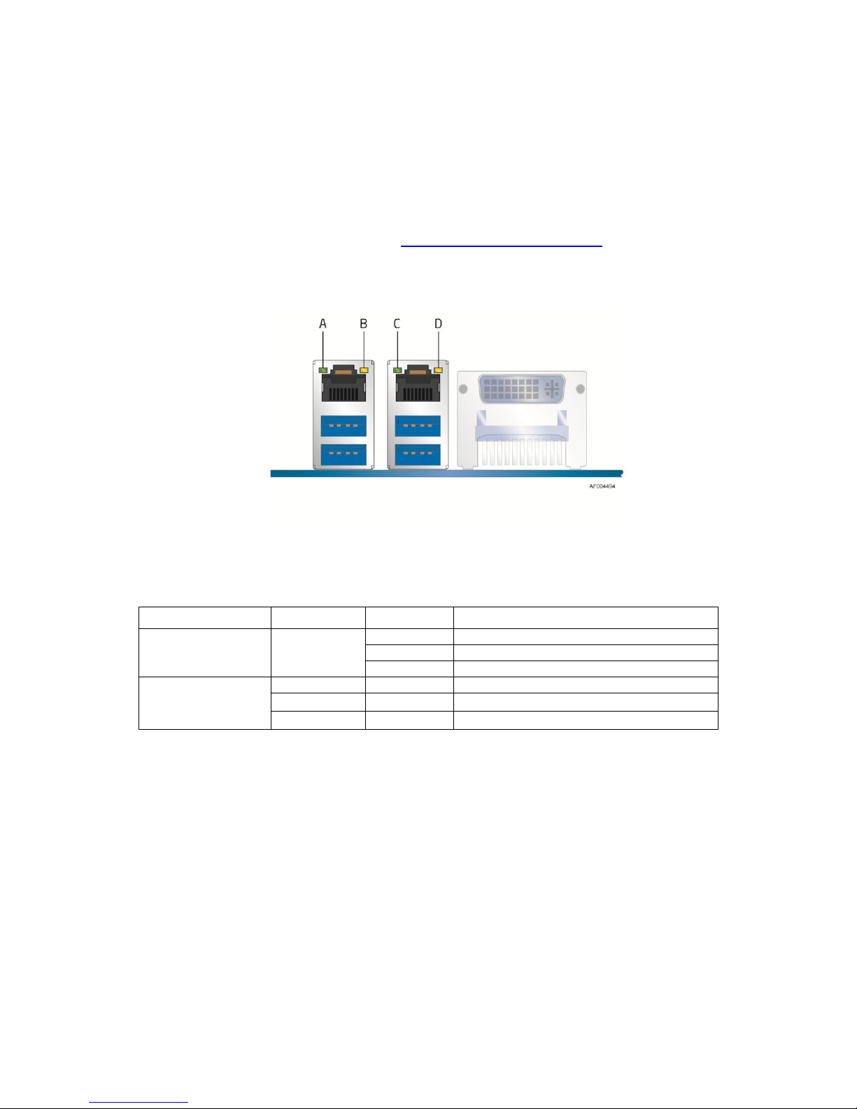
LED
LED Color
LED State
Indicates
A (Link/Activity)
C (Link/Activity)
Green
Off
LAN link is not established
On
LAN link is established
Blinking
LAN activity is occurring
B (Link Speed)
D (Link/Activity)
N/A
Off
10 Mb/s data rate
Green
On
100 Mb/s data rate
Yellow
On
1000 Mb/s data rate
LAN Subsystem
The LAN subsystem consists of the following:
Intel
RJ-45 LAN connector with integrated status LEDs
LAN software and drivers are available at http://downloadcenter.intel.com/.
Two LEDs are built into the RJ-45 LAN connector located on the back panel (see Figure 2). These
LEDs indicate the status of the LAN as shown in Table 3.
®
82574L and 82579LM Gigabit Ethernet Controllers (10/100/1000 Mbits/s)
Figure 2. LAN Connector LEDs
Table 3. LAN Connector LEDs
USB Support
The Server Board supports eight USB 2.0 ports (four ports routed to back panel connectors and four
ports routed to two onboard headers). The USB 2.0 ports are high-speed, full-speed, and low-speed
capable. USB 2.0 support requires both an operating system and drivers that fully support USB 2.0
transfer rates.
SATA Support
Intel® Server Board S1200KP provides two onboard 6.0 Gb/s Serial ATA (SATA) channels and
two onboard 3.0 Gb/s SATA channels.
10 Intel® Server Board S1200KP Product Guide
Page 20

Server Board Features
Expandability
Intel® Server Board S1200KP provides one PCI Express* 2.0 x16 (with Intel® Xeon® E3-1200
Processors or the 2nd Generation Intel® Core™ i3 Processors) or PCI Express* 3.0 x 16 (with Intel®
Xeon® E3-1200 V2 Processors or the 3rd Generation Intel® Core™ i3 Processors) connector for
system expansion.
Legacy I/O
The I/O controller provides the following features:
Low pin count (LPC) interface
Serial IRQ interface compatible with serialized IRQ support for PCI systems
Intelligent power management, including a programmable wake-up event interface
The BIOS Setup program provides configuration options for the legacy I/O controller.
BIOS
The BIOS provides the Power-On Self-Test (POST), the BIOS Setup program, and the PCI
Express* and SATA auto-configuration utilities. The BIOS is stored in the Serial Peripheral
Interface (SPI) Flash device.
The BIOS can be updated by following the instructions in Chapter 3 starting on page 43.
SATA Auto Configuration
If you install a SATA device (such as a hard drive) in your computer, the auto-configuration utility
in the BIOS automatically detects and configures the device for your computer. You do not need to
run the BIOS Setup program after installing a SATA device. You can override the autoconfiguration options by specifying manual configuration in the BIOS Setup program.
PCI*/PCI Express* Auto Configuration
If you install a Conventional PCI or PCI Express* add-in card in your computer, the PCI autoconfiguration utility in the BIOS automatically detects and configures the resources (IRQs, DMA
channels, and I/O space) for that add-in card. You do not need to run the BIOS Setup program after
you install a Conventional PCI or PCI Express* add-in card.
Security Passwords
The BIOS includes security features that restrict whether the BIOS Setup program can be accessed
and who can boot the computer. A supervisor password and a user password can be set for the
BIOS Setup and for booting the computer, with the following restrictions:
The supervisor password gives unrestricted access to view and change all Setup options. If only
the supervisor password is set, pressing <Enter> at the password prompt of Setup gives the user
restricted access to Setup.
Intel® Server Board S1200KP Product Guide 11
Page 21

Server Board Features
If both the supervisor and user passwords are set, you must enter either the supervisor password
or the user password to access Setup. Setup options are then available for viewing and changing
depending on whether the supervisor or user password was entered.
Setting a user password restricts who can boot the computer. The password prompt is displayed
before the computer is booted. If only the supervisor password is set, the computer boots
without asking for a password. If both passwords are set, you can enter either password to boot
the computer.
For instructions on resetting the password, go to Clearing Passwords on page 40.
Hardware Management
The hardware management features of Intel® Server Board S1200KP enable the board to be
compatible with the Wired for Management (WfM) specification. The board has several hardware
management features including the following:
Fan speed monitoring and control
Thermal and voltage monitoring
Chassis intrusion detection
12 Intel® Server Board S1200KP Product Guide
Page 22

Server Board Features
Hardware Monitoring and Fan Speed Control
The features of the hardware monitoring and fan speed control include:
Smart fan control provided by the legacy I/O controller, delivering acoustically-optimized
thermal management. Fan speed controllers and sensors are integrated into the legacy
I/O controller.
Thermal sensors in the processor and Intel
regulators and system memory.
Monitoring of system voltages to detect levels above or below acceptable values
Thermally monitored closed-loop fan control for all fans that can adjust fan speed as needed.
®
C206 PCH, as well as near the processor voltage
Fan Monitoring
Fan monitoring can be observed via the BIOS Setup program or third-party software.
Chassis Intrusion
The board supports a chassis security feature that detects if the chassis cover has been removed.
The security feature uses a mechanical switch on the chassis that can be connected to the chassis
intrusion header on the Server Board. See Figure 1 for the location of the chassis intrusion header.
Power Management
Power management is implemented at several levels, including software support through the
Advanced Configuration and Power Interface (ACPI) and the following hardware support:
Power connectors
Fan headers
LAN wake capabilities
Instantly Available PC technology (Suspend to RAM)
+5 V standby power indicator LED
Wake from USB
PCI Express* WAKE# signal support
Software Support
ACPI
ACPI gives the operating system direct control over the power management and Plug and Play
functions of a computer. The use of ACPI with the Server Board requires an operating system that
provides full ACPI support.
Intel® Server Board S1200KP Product Guide 13
Page 23

Server Board Features
Hardware Support
Power Connectors
ATX12V-compliant power supplies can turn off the computer power through system control. When
an ACPI-enabled computer receives the correct command, the power supply removes all nonstandby voltages.
When resuming from an AC power failure, the computer returns to the power state it was in before
power was interrupted (either on or off). The computer’s response can be set by using the Last
Power State feature in the BIOS Setup program’s Boot menu.
The Server Board has two power connectors. See Figure 20 on page 38 for the location of the
power connectors.
Fan Headers
The function/operation of the fans is as follows:
The fans are on when the board is in the ACPI S0 state.
The fans are off when the computer is in the ACPI S3, S4, or S5 state.
Each fan header is wired to a tachometer input.
All fan headers support closed-loop fan control that can adjust the fan speed or switch the fan
on or off as needed.
All fan headers have a +12 V DC connection (up to 12 V DC when using 3-wire chassis fans).
All fan headers are controlled by Pulse Width Modulation.
The chassis fan header supports linear fan control on 3-wire fans.
The Server Board has a 4-pin processor fan header and two 4-pin chassis fan headers compatible
with 4-wire and 3-wire chassis fans.
LAN Wake Capabilities
CAUTION
For LAN wake capabilities, the 5 V standby line for the power supply must
be capable of delivering adequate +5 V standby current. Failure to provide
adequate standby current when using this feature can damage the
power supply.
LAN wakeup capabilities enable remote wake-up of the computer through a network. The LAN
subsystem monitors network traffic and upon detecting a Magic Packet* frame, it asserts a wake-up
signal that powers up the computer.
14 Intel® Server Board S1200KP Product Guide
Page 24
Server Board Features
Instantly Available PC Technology
CAUTION
For Instantly Available PC technology, the 5 V standby line for the power
supply must be capable of delivering adequate +5 V standby current. Failure
to provide adequate standby current when using this feature can damage the
power supply and/or affect ACPI S3 sleep state functionality.
Instantly Available PC technology enables the board to enter the ACPI S3 (Suspend-to-RAM) sleep
state. Instantly Available PC technology enables the board to enter the ACPI S3 (Suspend-to-RAM)
sleep-state. While in the S3 sleep-state, the computer will appear to be off (the power supply is off
and the front panel power LED will behave as configured by the BIOS “S3 State Indicator” option).
When signaled by a wake-up device or event, the system quickly returns to its last known wake
state. When signaled by a wake-up device or event, the computer quickly returns to its last known
awake state.
The Server Board supports the PCI Bus Power Management Interface Specification. Add-in cards
that support this specification can participate in power management and can be used to wake
the computer.
The use of Instantly Available PC technology requires operating system support and PCI 2.2
compliant add-in cards, PCI Express* add-in cards, and drivers.
+5 V Standby Power Indicator LED
CAUTION
If the AC power has been switched off and the standby power indicator is
still lit, disconnect the power cord before installing or removing any devices
connected to the board. Failure to do so could damage the board and any of
the attached devices.
The Server Board’s standby power indicator, shown in Figure 3, is lit when there is standby power
still present on the board even when the computer appears to be off. For example, when this green
LED is lit, standby power is still present at the memory module sockets and the PCI
Express* connector.
Intel® Server Board S1200KP Product Guide 15
Page 25
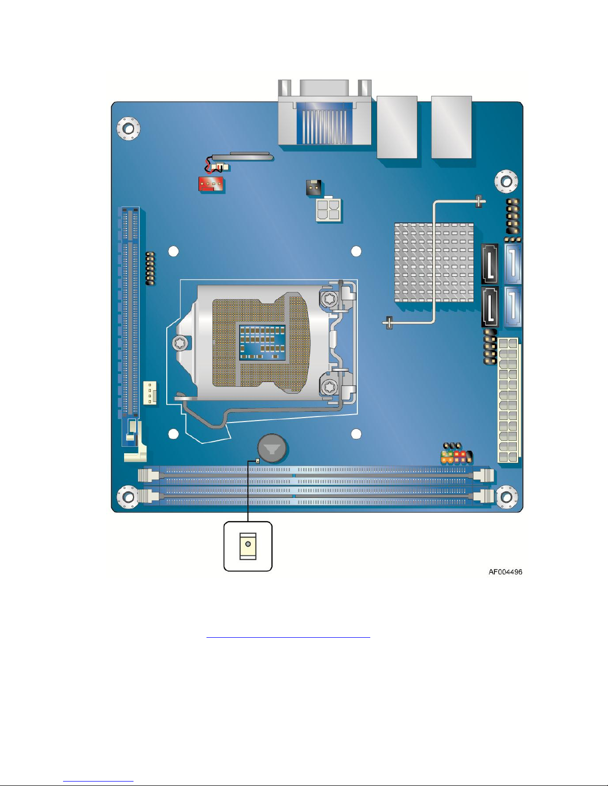
Server Board Features
Figure 3. Location of the Standby Power Indicator
For more information on standby current requirements for the Server Board, refer to the Technical
Product Specification at http://www.intel.com/products/server.
16 Intel® Server Board S1200KP Product Guide
Page 26

Server Board Features
Wake from USB
NOTE
Wake from USB requires the use of a USB peripheral that supports Wake
from USB and an operating system that supports Wake from USB.
USB bus activity wakes the computer from an ACPI S3 state.
PCI Express* WAKE# Signal Wake-up Support
When the WAKE# signal on a PCI Express* bus add-in card is asserted, the computer wakes from
an ACPI S3, S4, or S5 state.
Speaker
A speaker is mounted on the Server Board. The speaker provides audible error code (beep code)
information during the Power-On Self-Test (POST). Refer to Appendix A for a description of the
board’s beep codes.
Real-Time Clock Subsystem
A coin-cell battery (CR2032) powers the real-time clock and CMOS memory. When the computer
is not plugged into a wall socket, the battery has an estimated life of three years. When the
computer is plugged in, the standby current from the power supply extends the life of the battery.
The clock is accurate to 13 minutes/year at 25 ºC with standby power applied by the
power supply.
NOTE
If the battery and AC power fail, date and time values will be reset and the
user will be notified during the POST.
When the battery voltage drops below a certain level, the BIOS Setup program settings stored in
CMOS RAM (for example, the date and time) might not be accurate. Replace the battery with an
equivalent one. Go to page 41 for instructions on how to replace the battery.
Intel® Server Board S1200KP Product Guide 17
Page 27

Installing and Replacing Server Board Components
2 Installing and Replacing Server Board
Components
This chapter tells you how to:
Install the I/O shield
Install and remove the Server Board
Install and remove a processor
Install and remove memory
Install and remove a PCI Express* x16 card
Connect SATA drives
Connect to the internal headers
Connect chassis fan and power supply cables
Set the BIOS configuration jumper
Clear passwords
Replace the battery
Before You Begin
CAUTION
The procedures in this chapter assume familiarity with the general
terminology associated with personal computers and with the safety practices
and regulatory compliance required for using and modifying
electronic equipment.
Disconnect the computer from its power source and from any
telecommunications links, networks, or modems before performing any of
the procedures described in this chapter. Failure to disconnect power,
telecommunications links, networks, or modems before you open the
computer or perform any procedures can result in personal injury or
equipment damage. Some circuitry on the board can continue to operate even
though the front panel power button is off.
Follow these guidelines before you begin:
Always follow the steps in each procedure in the correct order.
Set up a log to record information about your computer, such as model, serial numbers,
installed options, and configuration information.
Electrostatic discharge (ESD) can damage components. Perform the procedures described in
this chapter only at an ESD workstation using an antistatic wrist strap and a conductive foam
pad. If such a station is not available, you can provide some ESD protection by wearing an
antistatic wrist strap and attaching it to a metal part of the computer chassis.
18 Intel® Server Board S1200KP Product Guide
Page 28

Installing and Replacing Server Board Components
Installation Precautions
When you install and test the Intel® Server Board, observe all warnings and cautions in the
installation instructions.
To avoid injury, be careful of:
Sharp pins on connectors
Sharp pins on printed circuit assemblies
Rough edges and sharp corners on the chassis
Hot components (such as processors, voltage regulators, and heat sinks)
Damage to wires that could cause a short circuit
Observe all warnings and cautions that instruct you to refer computer servicing to qualified
technical personnel.
Prevent Power Supply Overload
Do not overload the power supply output. To avoid overloading the power supply, make sure that
the calculated total current loads of all the modules within the computer is less than the output
current rating of each of the power supplies output circuits plus enough headroom for server board
power consumption.
Observe Safety and Regulatory Requirements
Read and follow the instructions in this section and the instructions supplied with the chassis and
associated modules. If you do not follow these instructions and the instructions provided by the
chassis and module suppliers, you increase your safety risk and the possibility of noncompliance
with regional laws and regulations. If the instructions for the chassis are inconsistent with these
instructions or the instructions for associated modules, contact the supplier to find out how you can
ensure that your computer meets safety and regulatory requirements.
Intel® Server Board S1200KP Product Guide 19
Page 29

Installing and Replacing Server Board Components
Installing the I/O Shield
The Server Board comes with an I/O shield. When installed in the chassis, the shield blocks radio
frequency transmissions, protects internal components from dust and foreign objects, and promotes
correct airflow within the chassis.
Install the I/O shield before installing the Server Board in the chassis. Place the shield inside the
chassis as shown in Figure 4. Press the shield into place so that it fits tightly and securely. If the
shield does not fit, obtain a properly sized shield from the chassis supplier.
Figure 4. Installing the I/O Shield
20 Intel® Server Board S1200KP Product Guide
Page 30

Installing and Replacing Server Board Components
Installing and Removing the Server Board
CAUTION
Only qualified technical personnel should perform this procedure.
Disconnect the computer from its power source before performing the
procedures described here. Failure to disconnect the power before you open
the computer can result in personal injury or equipment damage.
Refer to your Chassis Manual for instructions on installing and removing the Server Board.
Figure 5 shows the location of the mounting screw holes for Intel® Server Board S1200KP.
Figure 5. Intel® Server Board S1200KP Mounting Screw Hole Locations
Intel® Server Board S1200KP Product Guide 21
Page 31

Installing and Replacing Server Board Components
Installing and Removing a Processor
Instructions on how to install the processor on the Server Board are given below.
Installing a Processor
CAUTION
Before installing or removing a processor, make sure the AC power has been
removed by unplugging the power cord from the computer; the standby
power LED should not be lit (see Figure 3 on page 16). Failure to do so could
damage the processor and the board.
To install a processor, follow these instructions:
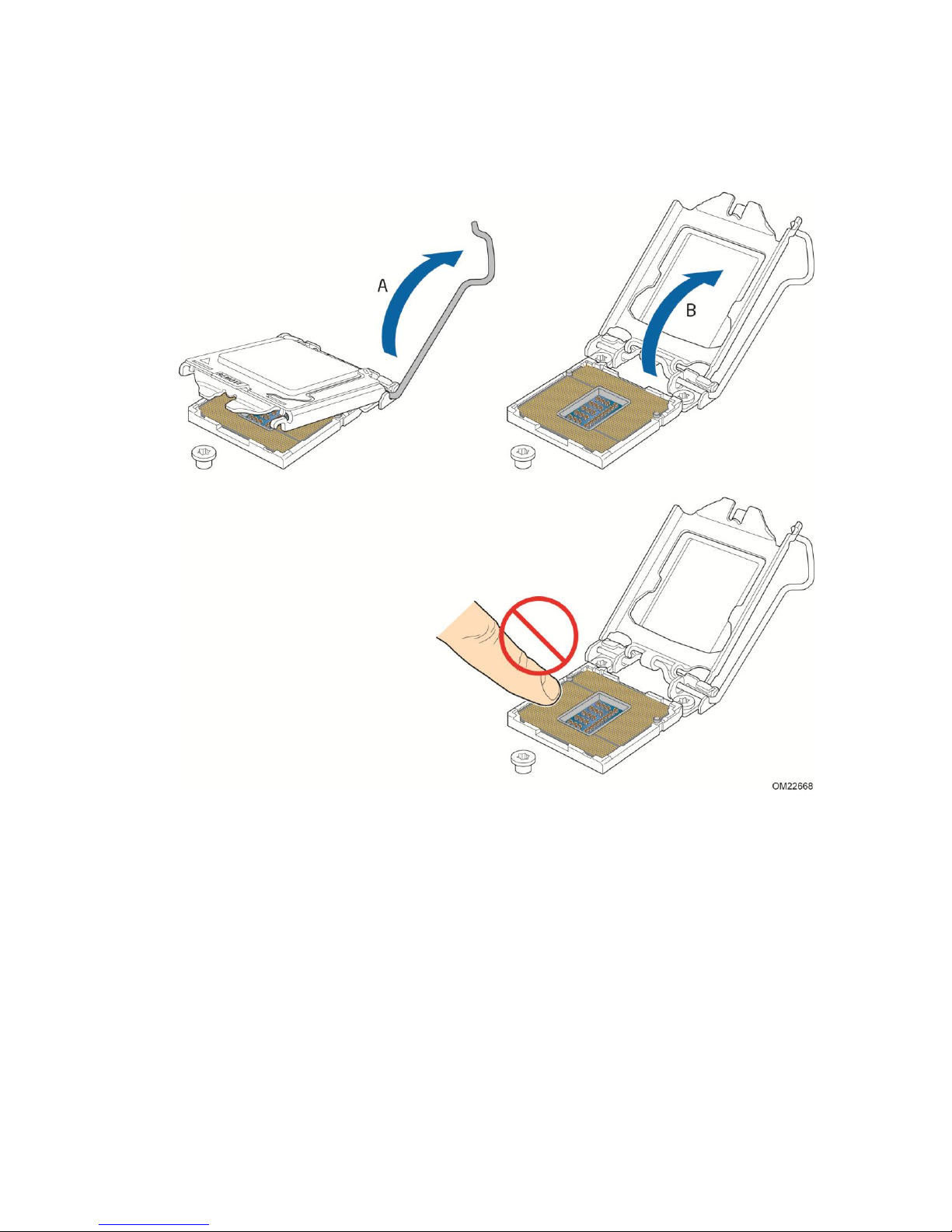
1. Observe the precautions in "Before You Begin" in page 18.
2. Unlatch the processor socket lever by pushing it down and away from the socket
(Figure 6, A, B).
Figure 6. Unlatch the Socket Lever
22 Intel® Server Board S1200KP Product Guide
Page 32
Installing and Replacing Server Board Components
3. Rotate the socket lever to lift the load plate away from the socket (Figure 7, A). Make sure that
the load plate is in the fully open position (Figure 7, B) while being careful not to damage
adjacent components. Do not touch the socket contacts.
Intel® Server Board S1200KP Product Guide 23
Figure 7. Lift the Load Plate
Page 33
Installing and Replacing Server Board Components
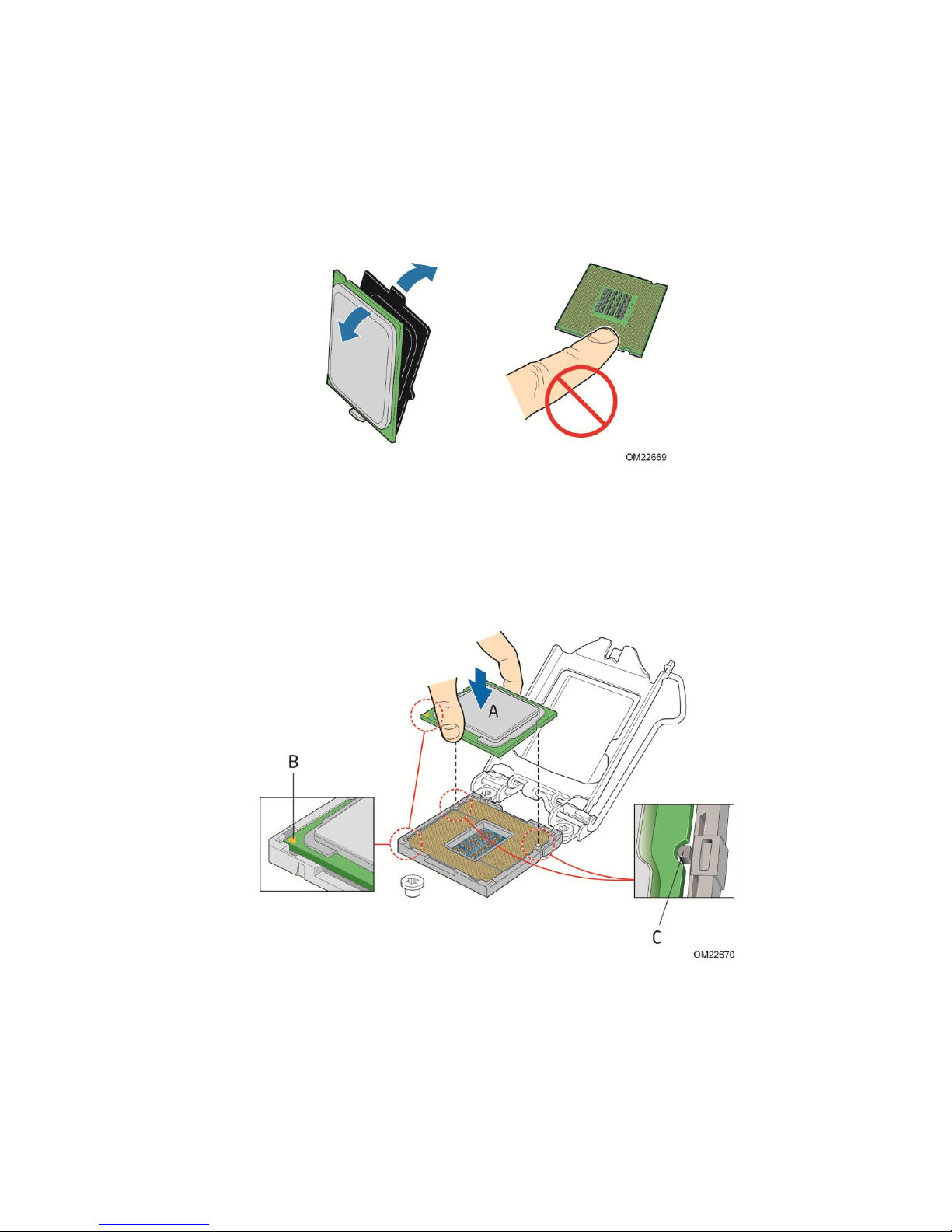
4. Remove the processor from its protective cover. Hold the processor only at the edges, being
careful not to touch the bottom of the processor (see Figure 8).
NOTE
Do not discard the processor cover. Always replace the processor cover if
you remove the processor from the socket.
Figure 8. Remove the Processor from the Protective Cover
5. Hold the processor with your thumb and index finger oriented as shown in Figure 9 to align
your fingers with the socket finger cutouts. Make sure that the processor Pin 1 indicator (gold
triangle) is aligned with the Pin 1 chamfer on the socket (Figure 9, B) and that the notches on
the processor align with the posts on the socket (Figure 9, C). Lower the processor straight
down without tilting or sliding it in the socket (Figure 9, A).
Figure 9. Install the Processor
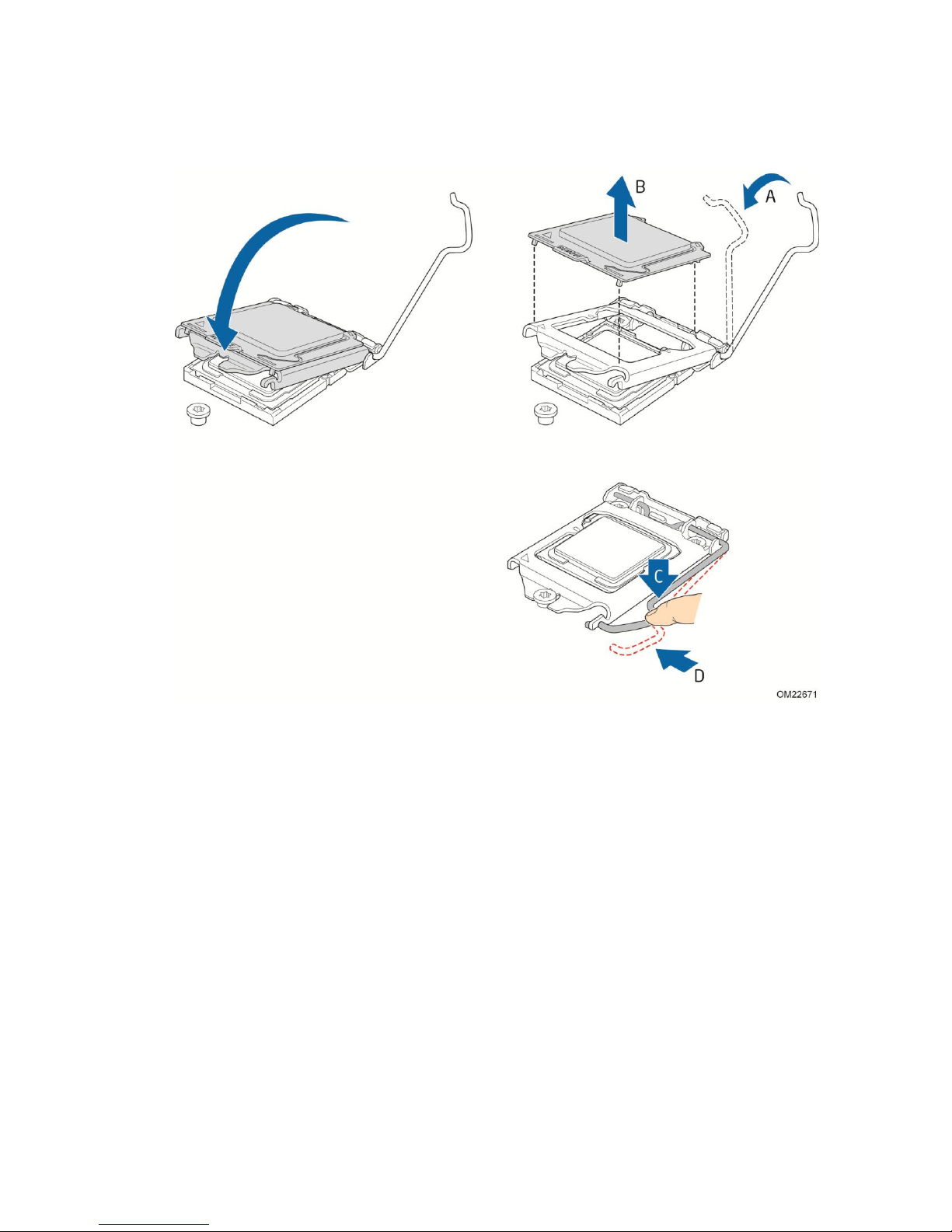
6. Carefully lower the socket lever (Figure 10, A) while making sure that the front edge of the
load plate slides under the shoulder screw cap as the lever is lowered. Latch the socket lever
24 Intel® Server Board S1200KP Product Guide
Page 34
Installing and Replacing Server Board Components
under the load plate tab (Figure 10, C, D). The socket cover (Figure 10, B) will pop off
as shown.
Figure 10. Secure the Load Plate in Place
7. Pick up the socket cover and remove it from the server board.
NOTE
Do not discard the socket cover; save it for possible future use. Always
replace the socket cover if you remove the processor from the socket.
Intel® Server Board S1200KP Product Guide 25
Page 35
Installing and Replacing Server Board Components
Installing a Processor Fan Heat Sink
Intel® Server Board S1200KP has mounting holes for a processor fan heat sink. For instructions on
how to attach the processor fan heat sink to the Server Board, refer to the boxed processor manual
or boxed thermal solution manual.
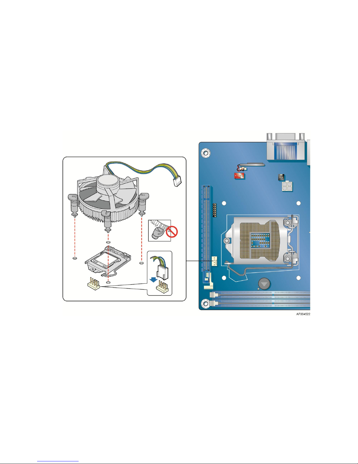
Connecting the Processor Fan Heat Sink Cable
Connect the processor fan heat sink power cable to the 4-pin processor fan header (see Figure 11).
A fan with a 4-pin connector as shown in Figure 11 is recommended.
Figure 11. Connecting the Processor Fan Heat Sink Power Cable to the
Removing the Processor
For instructions on how to remove the processor fan heat sink and processor, refer to the processor
installation manual.
26 Intel® Server Board S1200KP Product Guide
Processor Fan Header
Page 36
Installing and Replacing Server Board Components
Installing and Removing System Memory
NOTE
To be fully compliant with all applicable Intel® DRAM memory
specifications, the board requires DIMMs that support the Serial Presence
Detect (SPD) data structure.
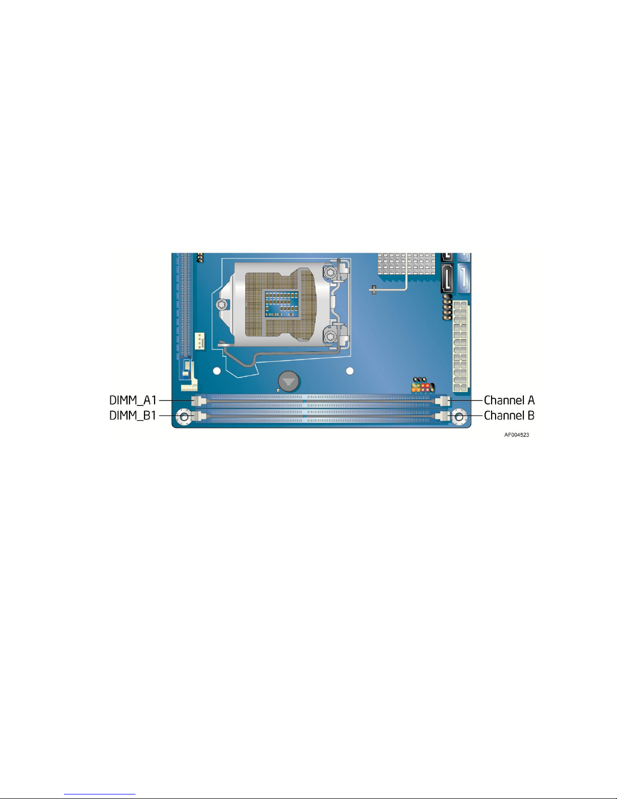
The server board has two 240-pin DDR3 DIMM sockets providing Channel A and Channel B. For
dual-channel performance, install a matched pair of DIMMs equal in speed and size
(see Figure 12).
NOTE
Figure 12. Dual Channel Memory Configuration Example
The Intel® Xeon® E3-1200 Processors, the 2nd Generation Intel® Core™ i3
Processors, Intel® Xeon® E3-1200 V2 Processors or the 3rd Generation Intel®
Core™ i3 Processors require memory to be installed in the DIMM_A1 (or
Channel A, DIMM 1) socket.
Intel® Server Board S1200KP Product Guide 27
Page 37
Installing and Replacing Server Board Components
Installing DIMMs
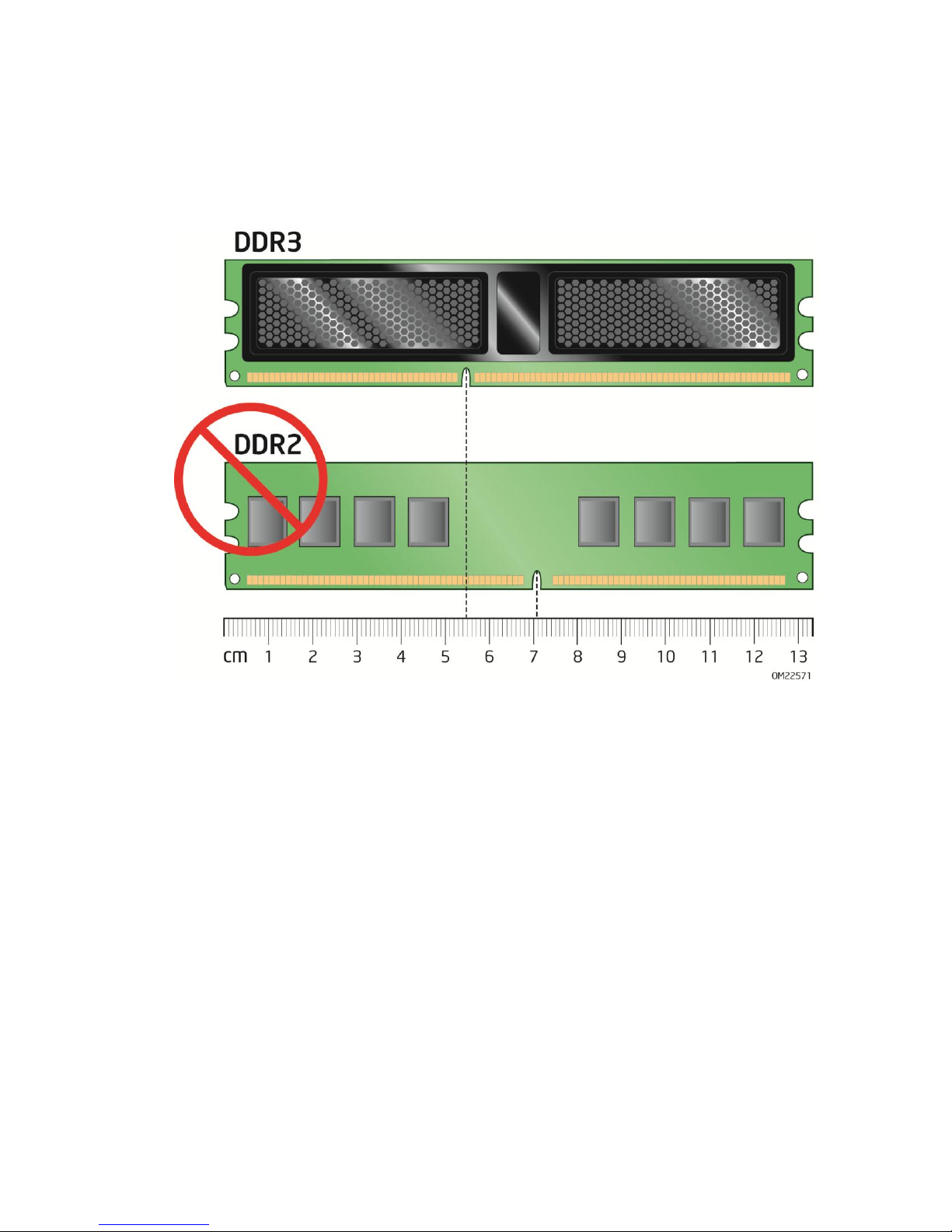
To make sure you have the correct DIMM, place it on the illustration of the DDR3 DIMM in Figure
13. All the notches should match with the DDR3 DIMM.
Figure 13. Use DDR3 DIMMs
28 Intel® Server Board S1200KP Product Guide
Page 38
Installing and Replacing Server Board Components
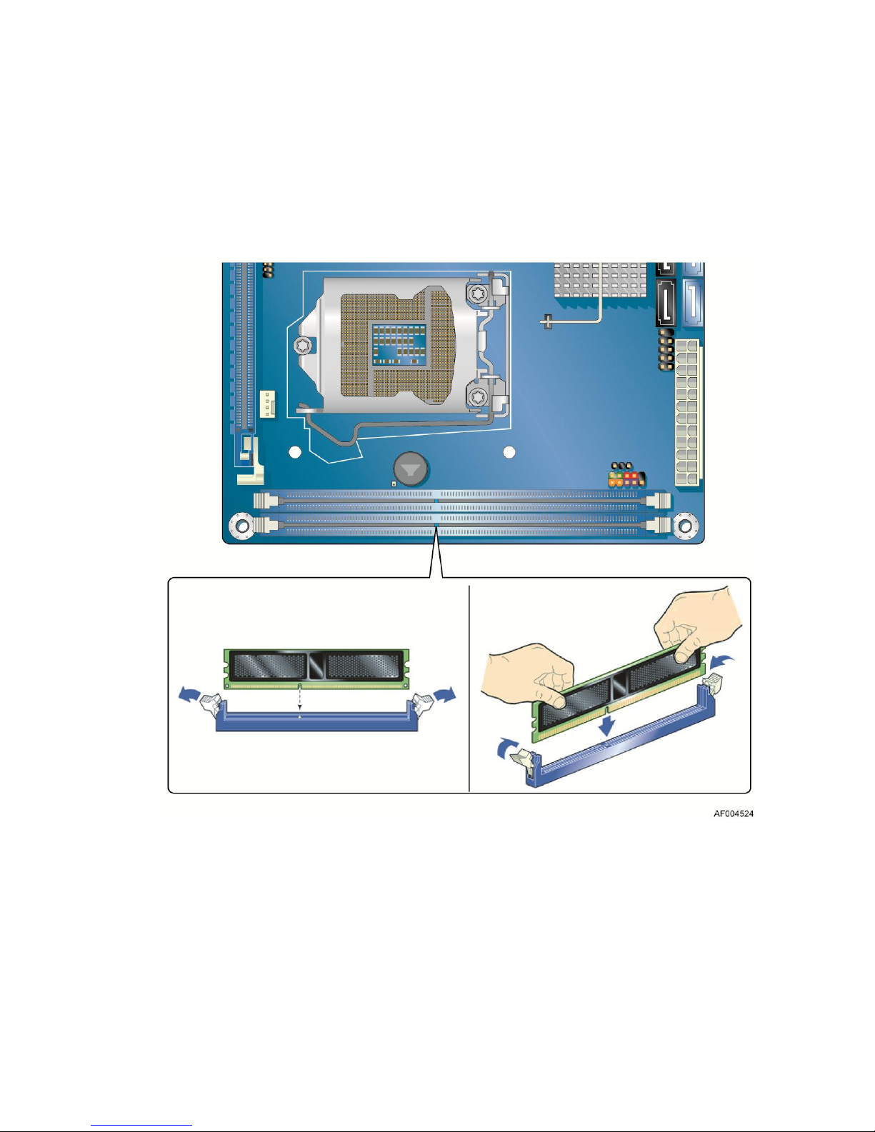
To install a DIMM, follow these steps:
1. Observe the precautions in "Before You Begin" on page 18.
2. Turn off all peripheral devices connected to the computer. Turn off the computer and
disconnect the AC power cord.
3. Remove the computer’s cover and locate the DIMM sockets (see Figure 14).
4. If a full length PCI Express* graphics card is installed in the PCI Express* x16 connector,
remove the card to gain full access to the DIMM sockets.
5. Make sure the clips at either end of the DIMM socket(s) are pushed outward to the open
position.
6. Holding the DIMM by the edges, remove it from its anti-static package.
7. Position the DIMM above the socket. Align the small notch at the bottom edge of the DIMM
with the keys in the socket (see inset in Figure 14).
8. Insert the bottom edge of the DIMM into the socket.
Intel® Server Board S1200KP Product Guide 29
Figure 14. Installing a DIMM
Page 39

Installing and Replacing Server Board Components
9. When the DIMM is inserted, push down on the top edge of the DIMM until the retaining clips
snap into place. Make sure the clips are firmly in place.
10. Reinstall the PCI Express* graphics card if one was removed in Step 4.
11. Replace the computer’s cover and reconnect the AC power cord.
Removing DIMMs
To remove a DIMM, follow these steps:
1. Observe the precautions in "Before You Begin" on page 18.
2. Turn off all peripheral devices connected to the computer. Turn off the computer.
3. Remove the AC power cord from the computer.
4. Remove the computer’s cover.
5. If a full length PCI Express* graphics card is installed in the PCI Express* x16 connector,
remove the card to gain access to the DIMMs.
6. Gently spread the retaining clips at each end of the DIMM socket. The DIMM pops out of
the socket.
7. Hold the DIMM by the edges, lift it away from the socket, and store it in an anti-static package.
8. Reinstall the PCI Express* graphics card if one was removed in Step 5 and reconnect any other
parts you removed or disconnected to reach the DIMMs.
9. Replace the computer’s cover and reconnect the AC power cord.
Installing and Removing PCI Express* x16 Graphics
Cards
Installing a PCI Express* x16 Graphics Card
CAUTION
Before installing a PCI Express* x16 graphics card, make sure that the tabs
on the DIMM sockets are in the upright position (closed); otherwise, they
CAUTION
may be damaged by the PCI Express* card during installation.
When installing a PCI Express* card, ensure that the card is fully seated in
the PCI Express* connector before you power on the system. If the card is
not fully seated in the connector, an electrical short may result across the
connector pins. Depending on the over-current protection of the power
supply, certain Server Board components and/or traces may be damaged.
30 Intel® Server Board S1200KP Product Guide
Page 40
Installing and Replacing Server Board Components
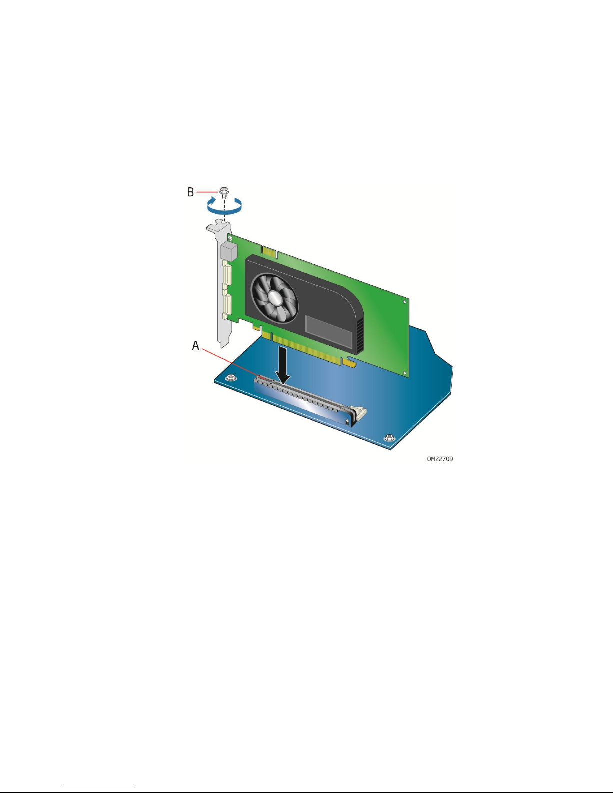
Follow these instructions to install a PCI Express* x16 graphics card:
1. Observe the precautions in "Before You Begin" on page 18.
2. Place the card in the PCI Express* x16 connector (Figure 15, A) and press down on the card
until it is completely seated in the connector and the card retention notch on the card snaps into
place around the retention mechanism pin on the connector.
3. Secure the card’s metal bracket to the chassis back panel with a screw (Figure 15, B).
4. Connect a monitor to the graphics card according to the manufacturer’s instructions.
Figure 15. Installing a PCI Express* x16 Graphics Card
Intel® Server Board S1200KP Product Guide 31
Page 41

Installing and Replacing Server Board Components
Removing a PCI Express* x16 Graphics Card
Follow these instructions to remove a PCI Express* x16 graphics card from a connector:
1. Observe the precautions in “Before You Begin” on page 18.
2. Disconnect the monitor cable from the graphics card back panel connector.
3. Remove the screw (Figure 16, A) that secures the card’s metal bracket to the chassis
back panel.
4. Push the card ejector lever down using the tip of a pencil or similar tool (Figure 16, B) in the
notch. This will release the card from the connector (C).
5. Pull the card straight up to remove it.
Figure 16. Removing a PCI Express* x16 Graphics Card
32 Intel® Server Board S1200KP Product Guide
Page 42

Installing and Replacing Server Board Components
Connecting SATA Drives
Use the included SATA cables to connect internal SATA drives. Each cable can be used to connect
one internal SATA drive to the Server Board’s SATA connectors. The blue SATA connectors
support 6.0 Gb/s and slower speed SATA devices while the black SATA connectors support 3.0
Gb/s and slower speed SATA devices.
For correct cable function:
1. Observe the precautions in “Before You Begin” on page 18.
2. Attach one end of the SATA cable to one of the SATA connectors on the board (Figure 17, A)
and attach the other end of the cable to the SATA drive data connector (Figure 17, B).
Intel® Server Board S1200KP Product Guide 33
Figure 17. Connecting a SATA Drive
Page 43

Installing and Replacing Server Board Components
Pin
Description
1
Ground
2
Intruder#
Connecting to the Internal Headers
Before connecting cables to any of the internal headers, observe the precautions in “Before You
Begin” on page 18. Figure 18 shows the location of the internal headers and connectors on Intel®
Server Board S1200KP.
Figure 18. Internal Headers
Chassis Intrusion Header
Figure 18, A shows the location of the chassis intrusion header. This header can be connected to a
mechanical switch on the chassis to detect if the chassis cover is removed. This switch should be in
the open position when the chassis cover is installed and closed when the cover is removed.
Table 4 shows the pin assignments and signal names for the chassis intrusion header.
Table 4. Chassis Intrusion Header Signal Names
34 Intel® Server Board S1200KP Product Guide
Page 44

Installing and Replacing Server Board Components
Pin
Signal Name
Pin
Signal Name
1
Power (+5 V)
2
Power (+5 V)
3
D- 4 D- 5 D+ 6 D+ 7 Ground
8
Ground
9
Key (no pin)
10
No Connection
Pin
Description
In/Out
Pin
Description
In/Out
Hard Drive Activity LED
Power LED
1
Hard disk LED pull-up to +5 V
Out 2 Front panel LED+
Out 3 Hard disk active LED
Out 4 Front panel LED-
Out
Reset Switch
On/Off Switch
5
Ground
6 Power switch
In
7
Reset switch
In 8 Ground
Power
Not Connected
9
Power
Out
10
No pin
Pin
Signal Name
In/Out
1
Front panel LED+
Out 2 No pin
3 Front panel LED-
Out
Front Panel USB 2.0 Headers
Figure 18, B shows the location of the front panel USB 2.0 headers and Table 5 shows their pin
assignments and signal names.
Table 5. USB 2.0 Header Signal Names
Front Panel Header
Figure 18, C shows the location of the front panel header. Table 6 shows the pin assignments and
signal names for the front panel header.
Table 6. Front Panel Header Signal Names
NOTE
When connecting individual wires from your chassis front panel to the front
panel header, be sure to observe the connection polarity. Positive wires are
usually solid color and negative wires are usually white or striped.
Alternate Front Panel Power LED Header
Figure 18, D shows the location of the alternate front panel power LED header. Pins 1 and 3 of this
header duplicate the signals on pins 2 and 4 of the front panel header. If your chassis has a three-pin
power LED cable, connect it to this header. Table 7 shows the pin assignments for the alternate
front panel header.
Table 7. Alternate Front Panel Power LED Header Signal Names
Intel® Server Board S1200KP Product Guide 35
Page 45

Installing and Replacing Server Board Components
Pin
Signal Name
Pin
Signal Name
1
CK_33M_DEBUG
2
GND
3
PLTRST#
4
LFRAME#
5
LAD0
6
LAD1
7
LAD2
8
LAD3
9
GND
10
GND
11
+3.3 V
12
+3.3 V
13
Not Connected
14
+3.3 V
Low Pin Count (LPC) Debug header
Figure 18, E shows the location of the low pin count debug header. Table 8 shows the pin
assignments and signal names for the low pin count debug header.
Table 8. LPC Debug Header
36 Intel® Server Board S1200KP Product Guide
Page 46

Installing and Replacing Server Board Components
Connecting Chassis Fan and Power Supply Cables
Connecting a Chassis Fan
Connect the chassis fan cable to the chassis fan header on the Server Board. Figure 19 shows the
location of the chassis fan header.
Figure 19. Location of the Chassis Fan Header
Intel® Server Board S1200KP Product Guide 37
Page 47

Installing and Replacing Server Board Components
Connecting Power Supply Cables
CAUTION
Failure to use an appropriate power supply and/or not connecting the 12 V
power connector (Figure 20, A) to the Server Board may result in damage to
the board or the system may not function properly.
Figure 20 shows the location of the power connectors. The 2 x 12 pin main power connector
(Figure 20, B) is backwards compatible with ATX12V power supplies with 2 x 10 connectors.
NOTE
If your power supply has a 2 x 10 main power connector, it is recommended
that you do not install a PCI Express* x16 graphics card unless it has a direct
connection to the power supply.
Figure 20. Connecting Power Supply Cables
1. Observe the precautions in "Before You Begin" on page 18.
2. Connect the 12 V processor core voltage power supply cable to the 2 x 2 pin connector (Figure
20, A).
3. Connect the main power supply cable to the 2 x 12 pin connector (Figure 20, B).
38 Intel® Server Board S1200KP Product Guide
Page 48
Installing and Replacing Server Board Components
Setting the BIOS Configuration Jumper
NOTE
Always turn off the power and unplug the power cord from the computer
before moving the jumper. Moving the jumper with the power on may result
in unreliable computer operation.
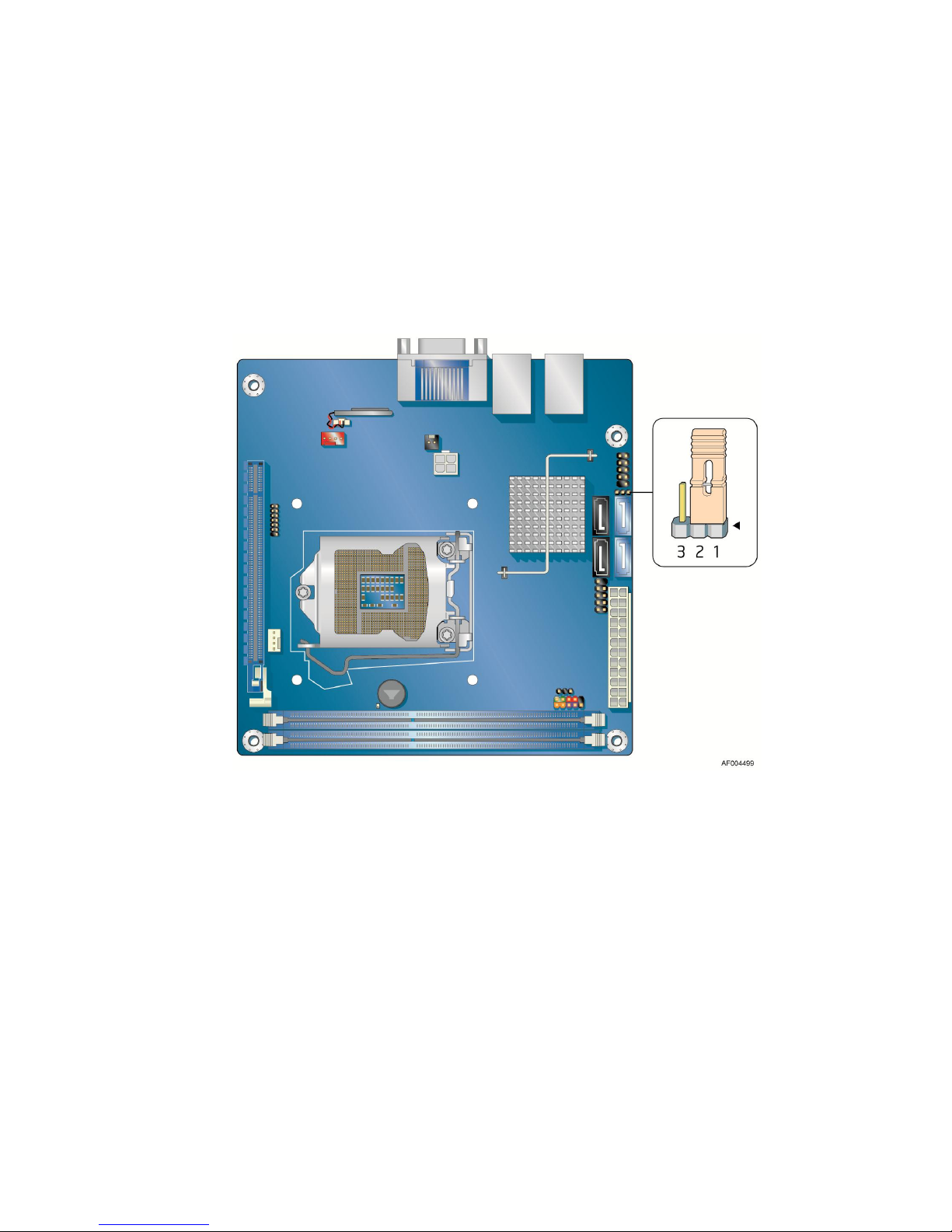
Figure 21 shows the location of the Server Board’s BIOS configuration jumper block.
Figure 21. Location of the BIOS Configuration Jumper Block
Intel® Server Board S1200KP Product Guide 39
Page 49
Installing and Replacing Server Board Components
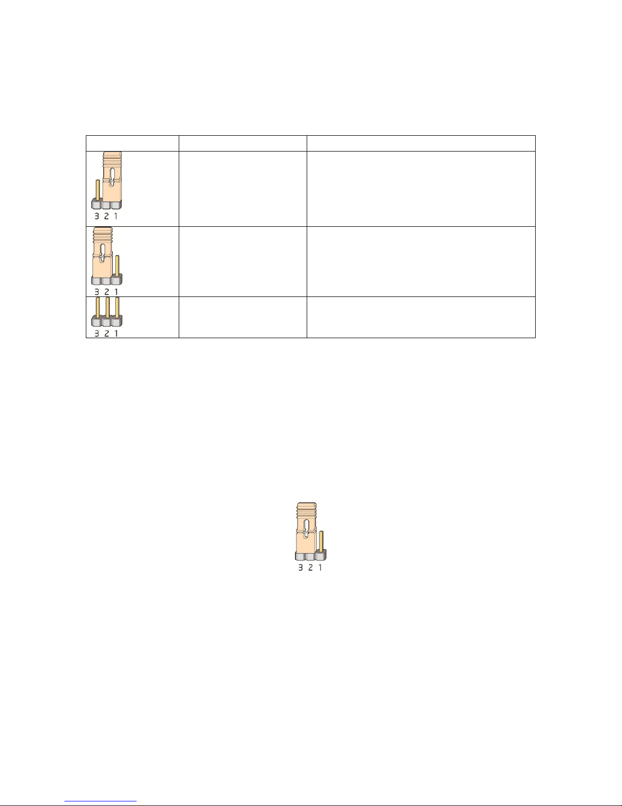
Jumper Setting
Mode
Description
Normal (default) (1-2)
The BIOS uses the current configuration and
passwords for booting.
Configure (2-3)
After the Power-On Self-Test (POST) runs, the BIOS
displays the Maintenance Menu. Use this menu to
clear passwords.
Recovery (None)
The BIOS recovers data in the event of a failed BIOS
update.
The three-pin BIOS jumper block enables board configuration to be done in the BIOS Setup
program. Table 9 shows the jumper settings for the BIOS Setup program modes.
Table 9. Jumper Settings for the BIOS Setup Program Modes
Clearing Passwords
This procedure assumes that the board is installed in the computer and the configuration jumper
block is set to normal mode.
1. Observe the precautions in "Before You Begin" on page 18.
2. Turn off all peripheral devices connected to the computer. Turn off the computer. Disconnect
the computer’s power cord from the AC power source (wall outlet or power adapter).
3. Remove the computer cover.
4. Find the configuration jumper block (see Figure 21).
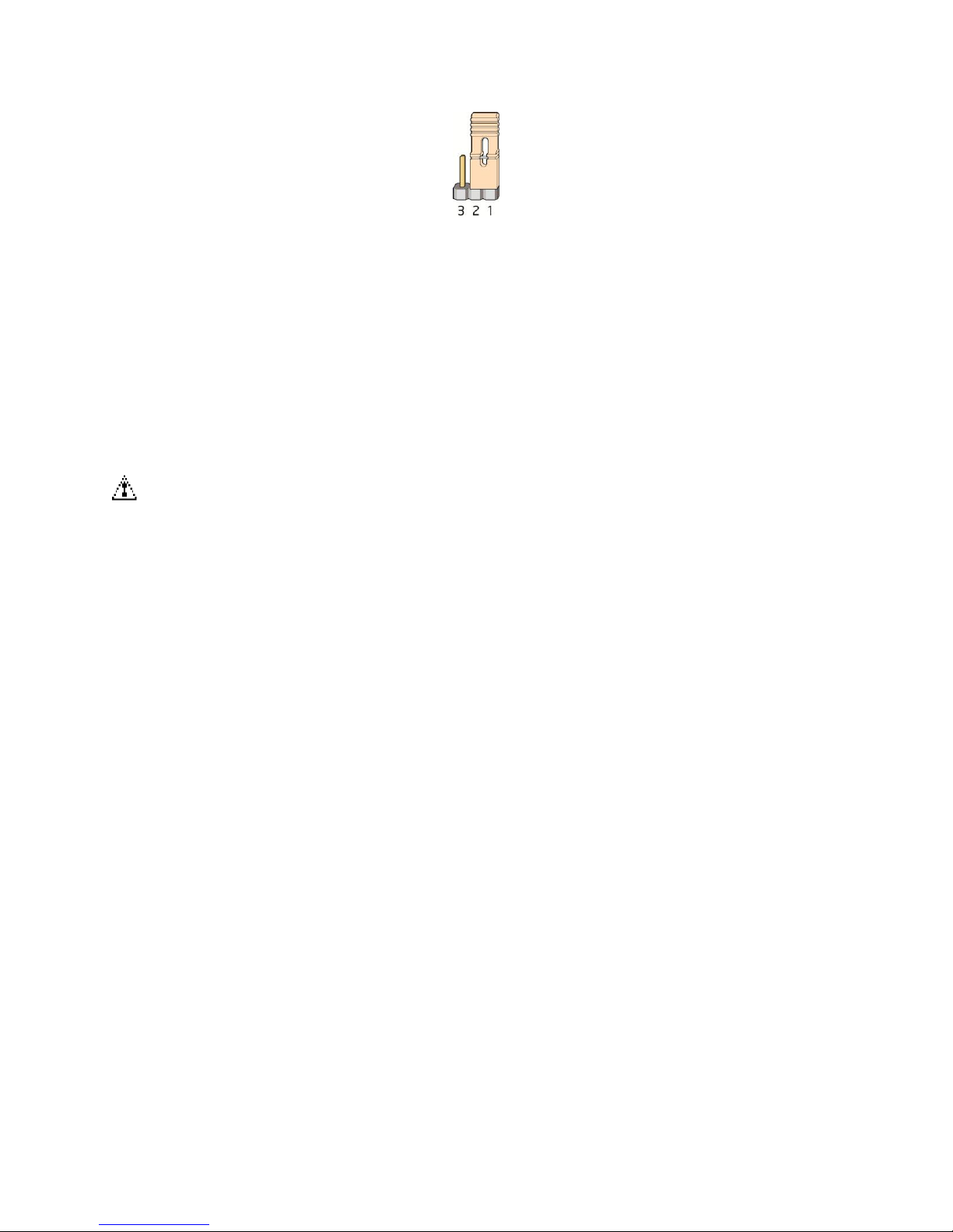
5. Place the jumper on pins 2-3 as shown below.
6. Replace the cover, plug in the computer, turn on the computer, and allow it to boot.
7. The computer starts the Setup program. Setup displays the Maintenance menu.
8. Use the arrow keys to select Clear Passwords. Press <Enter> and Setup displays a pop-up
screen requesting that you confirm clearing the password. Select “Yes” and press <Enter>.
Setup displays the maintenance menu again.
9. Press <F10> to save the current values and exit Setup.
10. Turn off the computer. Disconnect the computer’s power cord from the AC power source.
11. Remove the computer cover.
12. To restore normal operation, place the jumper on pins 1-2 as shown below.
40 Intel® Server Board S1200KP Product Guide
Page 50
Installing and Replacing Server Board Components
13. Replace the cover, plug in the computer, and turn on the computer.
Replacing the Battery
A coin-cell battery (CR2032) powers the real-time clock and CMOS memory. When the computer
is not plugged into a wall socket, the battery has an estimated life of three years. When the
computer is plugged in, the standby current from the power supply extends the life of the battery.
The clock is accurate to 13 minutes/year at 25 °C with 3.3 VSB applied.
When the voltage drops below a certain level, the BIOS Setup program settings stored in CMOS
RAM (for example, the date and time) might not be accurate. Replace the battery with an
equivalent one. Figure 22 on page 42 shows the location of the battery.
CAUTION
You will have the risk of explosion if the battery is replaced incorrectly.
Batteries should be recycled if possible. Disposal of used batteries must be in
accordance with local environmental regulations.
To replace the battery, follow these steps:
1. Observe the precautions in "Before You Begin" (see page 18).
2. Turn off all peripheral devices connected to the computer. Disconnect the computer’s power
cord from the AC power source (wall outlet or power adapter).
3. Remove the computer cover.
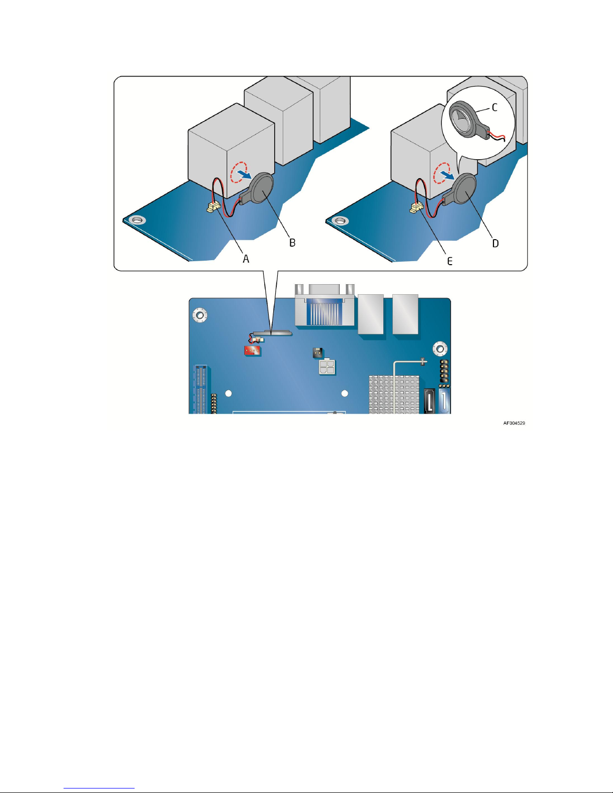
4. Locate the battery on the board (see Figure 22).
5. Disconnect the battery wires from the connector (Figure 22, A) and remove the battery (Figure
22, B) from the back of the I/O stack
6. To install the new battery, remove the paper backing (Figure 22, C) from the battery adhesive
pad, attach the battery to the I/O stack, and connect the wires (Figure 22, E) to the server board.
7. Replace the computer cover.
Intel® Server Board S1200KP Product Guide 41
Page 51
Installing and Replacing Server Board Components
Figure 22. Removing the Battery
42 Intel® Server Board S1200KP Product Guide
Page 52

Updating the BIOS
3 Updating the BIOS
The BIOS Setup program can be used to view and change the BIOS settings for the computer. You
can access the BIOS Setup program by pressing the <F2> key after the Power-On Self-Test (POST)
memory test begins and before the operating system boot begins.
This chapter tells you how to update the BIOS by either using the Intel® Flash Memory Update
Utility or the <F7> key, and how to recover the BIOS if an update fails.
Updating the BIOS with the Intel® Flash Memory
Update Utility
You can use the information in this section to update the BIOS using the Intel® Flash Memory
Update Utility.
Obtaining the BIOS Update File
You can update to a new version of the BIOS by using the Intel® Flash Memory BIOS update file.
The Intel® Flash Memory BIOS update file is a compressed file that contains the files you need to
update the BIOS. The BIOS update file contains:
New BIOS file (including the Intel
Intel
Intel
You can obtain either of these files through your computer supplier or by navigating to the Intel®
Server Board S1200KP page on the Intel® World Wide Web site Download Center at
http://downloadcenter.intel.com.
On the S1200KP page, click on the “BIOS Update” link and then select the Iflash BIOS
Update file.
®
Integrator Toolkit Configuration File (optional)
®
Flash Memory Update Utility
®
Management Engine (Intel® ME) Firmware Image))
Updating the BIOS with the Intel® Flash Memory Update Utility
With the Intel® Flash Memory Update Utility you can update the system BIOS from a bootable
USB flash drive, or other bootable USB media. The BIOS update files can be extracted locally to
your hard drive and copied to a bootable USB flash drive or other bootable USB media.
The Intel® Flash Memory Update Utility allows you to:
Update the BIOS and Intel
Update the language section of the BIOS
®
Management Engine in flash memory
NOTE
Review the instructions distributed with the update utility before attempting a
BIOS update.
Intel® Server Board S1200KP Product Guide 43
Page 53

Updating the BIOS
CAUTION
Do not interrupt the process or the system, for it may not function properly.
1. Uncompress the BIOS update file and copy the .BIO file, IFLASH.EXE, and .ITK file
(optional) to a bootable USB flash drive or other bootable USB media.
2. Configure the BIOS or use the F10 option during POST to boot to the USB device.
3. Manually run the IFLASH.EXE file from the USB device and manually update the BIOS.
44 Intel® Server Board S1200KP Product Guide
Page 54

Updating the BIOS
Updating the BIOS Using the F7 Function Key
To use this BIOS update method:
1. Download and save the Recovery BIOS (.BIO) file to a temporary directory.
2. Copy the .BIO to a USB thumb drive.
3. Plug the thumb drive into a USB port of the target computer.
4. Shut down the target computer.
5. Enable the F7 prompt display:
a. Power the computer on.
b. Enter the BIOS Setup by pressing F2 during boot.
c. Go to the Advanced > Boot Configuration menu.
d. Enable Display F7 to Update BIOS
e. Press F10 to save and exit.
6. During boot, when the F7 prompt is displayed, press F7 to enter the BIOS Flash Update tool.
7. Select the USB thumb drive and press Enter.
8. Select the .BIO file and press Enter
9. Confirm you want to update the BIOS by pressing Enter.
10. Wait 2-5 minutes for the update to complete.
11. Remove the thumb drive.
12. Restart the computer.
Recovering the BIOS
It is unlikely that anything will interrupt the BIOS update; however, if an interruption occurs, the
BIOS could be damaged. Due to BIOS size and recovery requirements, a CD-R with the .BIO file
in the root directory will be required.
You can obtain the Recovery BIOS Update file through your computer supplier or by navigating to
the Intel® Server Board S1200KP page on the Intel® World Wide Web site Download Center at
http://downloadcenter.intel.com.
On the S1200KP page, click on the “BIOS Update” link and then select the Recovery BIOS
Update file.
Intel® Server Board S1200KP Product Guide 45
Page 55

Appendix A: Error Messages and Indicators
Type
Pattern
Frequency/Comments
F2 Setup/F10 Boot
Menu Prompt
One 0.5 second beep when the BIOS is ready to
accept keyboard input
932 Hz
BIOS update in progress
None
Video error (no add-in
graphics card installed)
On-off (1.0 second each) two times, then a
2.5-second pause (off), the entire pattern repeats
(beeps and pause) once and the BIOS will
continue to boot.
932 Hz
For processors requiring an
add-in graphics card
Memory error
On-off (1.0 second each) three times, then a
2.5-second pause (off), the entire pattern repeats
(beeps and pause) until the system is powered
off.
932 Hz
Thermal trip warning
Alternate high and low beeps (1.0 second each)
for eight beeps followed by system shut down.
High beep 2000 Hz
Low beep 1500 Hz
Type
Pattern
Note
F2 Setup/F10 Boot
Menu Prompt
None
BIOS update in progress
Off when the update begins, then on for
0.5 second, then off for 0.5 second. The pattern
repeats until the BIOS update is complete.
Video error (no add-in
graphics card installed)
On-off (0.5 second each) two times, then a
3.0-second pause (off), the entire pattern repeats
(blink and pause) until the system is powered off.
For processors requiring an
add-in graphics card
Memory error
On-off (0.5 second each) three times, then a
3.0-second pause (off), the entire pattern repeats
(blinks and pause) until the system is powered off.
Thermal trip warning
Each beep will be accompanied by the following
blink pattern: .25 seconds on, .25 seconds off, .25
seconds on, .25 seconds off. This results in a total
of 32 blinks.
Appendix A: Error Messages and Indicators
Intel® Server Board S1200KP reports POST errors in two ways:
By sounding a beep code and blinking the front panel power LED
By displaying an error message on the monitor
BIOS Error Codes
Whenever a recoverable error occurs during POST, the BIOS causes the board’s speaker to beep
and the front panel power LED to blink an error message indicating the problem (see Table 10).
Table 10. BIOS Beep Codes
Table 11. Front-panel Power LED Blink Codes
46 Intel® Server Board S1200KP Product Guide
Page 56
Appendix A: Error Messages and Indicators
Error Message
Explanation
CMOS Battery Low
The battery may be losing power. Replace the battery soon.
CMOS Checksum Bad
The CMOS checksum is incorrect. CMOS memory may have been
corrupted. Run Setup to reset values.
Memory Size Decreased
Memory size has decreased since the last boot. If no memory was
removed, then memory may be bad.
No Boot Device Available
System did not find a device to boot.
BIOS Error Messages
When a recoverable error occurs during the POST, the BIOS displays an error message describing
the problem. Table 12 gives an explanation of the BIOS error messages.
Table 12. BIOS Error Messages
Intel® Server Board S1200KP Product Guide 47
 Loading...