

Page 1

R
Intel® 6700PXH 64-bit PCI Hub
Thermal/Mechanical Design Guidelines
August 2004
Document Number: 302817-003
Page 2

R
INFORMATION IN THIS DOCUMENT IS PROVIDED IN CONNECTION WITH INTEL® PRODUCTS. EXCEPT AS PROVIDED IN INTEL'S TERMS
AND CONDITIONS OF SALE FOR SUCH PRODUCTS, INTEL ASSUMES NO LIABILITY WHATSOEVER, AND INTEL DISCLAIMS ANY EXPRESS
OR IMPLIED WARRANTY RELATING TO SALE AND/OR USE OF INTEL PRODUCTS, INCLUDING LIABILITY OR WARRANTIES RELATING TO
FITNESS FOR A PARTICULAR PURPOSE, MERCHANTABILITY, OR INFRINGEMENT OF ANY PATENT, COPYRIGHT, OR OTHER
INTELLECTUAL PROPERTY RIGHT.
Intel may make changes to specifications, product descriptions, and plans at any time, without notice.
Designers must not rely on the absence or characteristics of any features or instructions marked “reserved” or “undefined.” Intel res erves these for
future definition and shall have no responsibility whatsoever for conflicts or incompatibilities arising from future changes to them.
®
The Intel
from published specifications. Current characterized errata are available upon request.
Contact your local Intel sales office or your distributor to obtain the latest specifications and before placing your product order.
Copi es of doc uments whic h hav e an order number and are r efer enced in this doc um ent, or ot her Int el liter atu re, may b e obt ain ed by calling
1-800-548-4725, or by visiting Intel's websit e at http://www.intel.com.
Int el is a tr adem ark or r egister ed tradem ark of Intel Cor por ation or its subs idi aries in the Unit ed St ates and oth er c ountries.
Copyright © 2004, Intel Corporation. All rights reserved.
* Other brands and names may be claimed as the property of others.
2 Intel
6700PXH 64-bit PCI Hub chipset component may contain design defects or errors known as errata, which may cause the product to deviate
®
6700PXH 64-bit PCI Hub Thermal/Mechanical Design Guidelines
Page 3

R
Contents
1 Introduction.....................................................................................................................7
1.1 Definition of Terms...............................................................................................7
1.2 Reference Documents .........................................................................................8
2 Packaging Technology...................................................................................................9
2.1 Package Mechanical Requirements ...................................................................10
3 Thermal Specifications.................................................................................................11
3.1 Thermal Design Power (TDP) ............................................................................11
3.2 Die Case Temperature Specifications................................................................11
4 Thermal Simulation ......................................................................................................13
5 Thermal Metrology........................................................................................................15
5.1 Die Case Temperature Measurements...............................................................15
5.1.1 Zero Degree Angle Attach Methodology................................................15
6 Reference Thermal Solution ........................................................................................17
6.1 Operating Environment ......................................................................................17
6.2 Heatsink Performance........................................................................................17
6.3 Mechanical Design Envelope.............................................................................18
6.4 Board-Level Components Keepout Dimensions .................................................18
6.5 Torsional Clip Heatsink Thermal Solution Assembly ..........................................18
6.5.1 Heatsink Orientation..............................................................................20
6.5.2 Extruded Heatsink Profiles ....................................................................20
6.5.3 Mechanical Interface Material................................................................20
6.5.4 Thermal Interface Material.....................................................................21
6.5.5 Heatsink Clip .........................................................................................21
6.5.6 Clip Retention Anchors..........................................................................22
6.6 Reliability Guidelines..........................................................................................22
A Thermal Solution Component Suppliers.....................................................................23
A.1 Torsional Clip Heatsink Thermal Solution...........................................................23
B Mechanical Drawings ...................................................................................................25
®
Intel
6700PXH 64-bit PCI Hub Thermal/Mechanical Design Guidelines 3
Page 4

Figures
Tables
2-1. Intel® 6700PXH 64-bit PCI Hub Package Dimensions (Top View) .............................9
2-2. Intel® 6700PXH 64-bit PCI Hub Package Dimensions (Side View).............................9
2-3. Intel® 6700PXH 64-bit PCI Hub Package Dimensions (Bottom View) ......................10
5-1. Zero Degree Angle Attach Heatsink Modifications ...................................................16
5-2. Zero Degree Angle Attach Methodology (Top View) ................................................16
6-1. Reference Heatsink Measured Thermal Performance Versus Approach Velocity ....17
6-2. Torsional Clip Heatsink Volumetric Envelope for the Intel® 6700PXH 64-bit PCI Hub
Chipset Component ...........................................................................................18
6-3. Torsional Clip Heatsink Board Component Keepout ................................................19
6-4. Retention Mechanism Component Keepout Zones ..................................................19
6-5. Torsional Clip Heatsink Assembly............................................................................20
6-6 Heatsink Rails to PXH Package Footprint .................................................................20
6-7. Torsional Clip Heatsink Extrusion Profile .................................................................21
B-1. Torsional Clip Heatsink Assembly Drawing .............................................................26
B-2. Torsional Clip Heatsink Drawing..............................................................................27
B-3.Torsional Clip Drawing .............................................................................................28
R
3-1. Intel® 6700PXH 64-bit PCI Hub Thermal Specifications ...........................................11
6-1. Chomerics* T710 TIM Performance as a Function of Attach Pressure.....................21
6-2. Reliability Guidelines ...............................................................................................22
B-1. Mechanical Drawing List..........................................................................................25
4 Intel
®
6700PXH 64-bit PCI Hub Thermal/Mechanical Design Guidelines
Page 5
R
Revision History
Revision
Number
-001
-002
-003
Description Date
Initial release Jul 2004
Added “reference thermal solution rails to PXH package” footprint drawing in
Section 6.5
Removed inaccurate text in three graphics
Aug 2004
Sep 2004
®
Intel
6700PXH 64-bit PCI Hub Thermal/Mechanical Design Guidelines 5
Page 6

Introduction
R
6 Intel
®
6700PXH 64-bit PCI Hub Thermal/Mechanical Design Guidelines
Page 7

R
1 Introduction
As the complexity of computer systems increases, so do the power dissipation requirements. Care
must be taken to ensure that the additional power is properly dissipated. Typical methods to improve
heat dissipation include selective use of ducting, and/or passive heatsinks.
The goals of this document are to:
• Outline the thermal and Mechanical operating limits and specifications for the Intel
6700PXH 64-bit PCI Hub component.
• Describe a reference thermal solution that meets the specification of Intel
PCI Hub component.
Properly designed thermal solution provides adequate cooling to maintain the PXH component die
temperatures at or below thermal specifications. This is accomplished by providing a low localambient temperature, ensuring adequate local airflow, and minimizing the die to local-ambient
thermal resistance. By maintaining the PXH component die temperature at or below the specified
limits, a system designer can ensure the proper functionality, performance, and reliability of the
chipset. Operation outside the functional limits can degrade system performance and may cause
permanent changes in the operating characteristics of the component.
®
®
6700PXH 64-bit
The simplest and most cost effective method to improve the inherent system cooling characteristics
is through careful chassis design and placement of fans, vents, and ducts. When additional cooling is
required, component thermal solutions may be implemented in conjunction with system thermal
solutions. The size of the fan or heatsink can be varied to balance size and space constraints with
acoustic noise.
This document addresses thermal design and specifications for the Intel
components only. For thermal design information on other chipset components, refer to the
respective component datasheet.
Unless otherwise specified, the term “PXH” refers to the Intel
1.1 Definition of Terms
BGA Ball grid array. A package type, defined by a resin-fiber substrate, onto which a die is
mounted, bonded and encapsulated in molding compound. The primary electrical
interface is an array of solder balls attached to the substrate opposite the die and molding
compound.
BLT Bond line thickness. Final settled thickness of the thermal interface material after
installation of heatsink.
MCH Memory controller hub. The chipset component that contains the processor interface, the
memory interface, and the hub interface.
®
PXH Intel
6700PXH 64-bit PCI Hub. The chipset component that performs PCI bridging
functions between the PCI Express* interface and the PCI Bus. It contains two PCI bus
interfaces that can be independently configured to operate in PCI (33 or 66 MHz) or
PCI-X mode 1 (66, 100, or 133 MHz), for either 32 or 64 bit PCI devices.
®
6700PXH 64-bit PCI Hub
®
6700PXH 64-bit PCI Hub.
®
Intel
6700PXH 64-bit PCI Hub Thermal/Mechanical Design Guidelines 7
Page 8

Introduction
R
T
case_max
Maximum die temperature allowed. This temperature is measured at the geometric center
of the top of the package die.
T
Minimum die temperature allowed. This temperature is measured at the geometric center
case_min
of the top of the package die.
TDP Thermal design power. Thermal solutions should be designed to dissipate this target
power level. TDP is not the maximum power that the chipset can dissipate.
1.2 Reference Documents
The reader of this specification should also be familiar with material and concepts presented in the
following documents:
• Intel® 82801EB I/O Controller Hub 5 (ICH5) and Intel® 82801ER I/O Controller Hub 5 R
(ICH5R) Datasheet
• Intel® 82801EB I/O Controller Hub 5 (ICH5) and Intel® 82801ER I/O Controller Hub 5 R
(ICH5R) Thermal Design Guide
• Intel®6700PXH 64-bit PCI Hub (PXH) Thermal/Mechanical Design Guide
• Intel® 6700PXH 64-bit PCI Hub (PXH) Datasheet
• Intel® 6700PXH 64-bit PCI Hub (PXH) Specification Update
• Intel® 6300ESB I/O Controller Hub Thermal and Mechanical Design Guide
• Intel® 6300ESB I/O Controller Hub Datasheet
• Intel® 6300ESB I/O Controller Hub (ICH) Specification Update
• BGA/OLGA Assembly Development Guide
• Various system thermal design suggestions (http://www.formfactors.org)
Note: Unless otherwise specified, these documents are available through your Intel field sales
representative. Some documents may not be available at this time.
8 Intel
®
6700PXH 64-bit PCI Hub Thermal/Mechanical Design Guidelines
Page 9
R
2 Packaging Technology
The Intel® 6700PXH 64-bit PCI Hub component uses a 31 mm x 31 mm, 8-layer FC-BGA package
(see Figure 2-1Figure 2-1Figure 2-1, Figure 2-2Figure 2-2Figure 2-2, and Figure 2-3Figure
2-3Figure 2-3).
Figure 2-1. Intel® 6700PXH 64-bit PCI Hub Package Dimensions (Top View)
Die
Keepout
Area
21.00 mm17.00 mm
31.00 mm
0.547 in.
Handling
Exclusion
Area
0.247 in .
0.200 in.
0.291 in.
0.491 in.
PXH
Die
17.00 mm
21.00 mm
31.00 mm
Figure 2-2. Intel® 6700PXH 64-bit PCI Hub Package Dimensions (Side View)
2.445 ± 0.102 mm
Substrate
2.010 ± 0.099 mm
0.435 ± 0.025 mm
See Note 3
Notes:
1.Primary datum -C- and seating plan are defined by the spherical crowns of the solder balls (shown before motherboard attach).
2.All dimensions and tolerances conform to ANSI Y14.5M-1994.
3.BGA has a pre-SMT height of 0.5 mm and post-SMT height of 0.41-0.46 mm.
4.Shown before motherboard attach; FCBGA has a convex (dome shaped) orientation before reflow and is expected to have a slightly
concave (bowl shaped) orientation after reflow.
0.84 ± 0.05 mm
Decoup
Cap
Die
Seating Plane
0.7 mm Max
0.20
See note 4.
0.20
See Note 1
–C–
®
Intel
6700PXH 64-bit PCI Hub Thermal/Mechanical Design Guidelines 9
Page 10

Packaging TechnologyPackaging TechnologyPackaging Technology
®
Figure 2-3. Intel
NOTES:
6700PXH 64-bit PCI Hub Package Dimensions (Bottom View)
AD
AC
AB
AA
Y
W
V
U
T
R
1.270
(0.895)
P
N
M
L
K
J
H
G
F
E
D
C
+
B
+
A
234567891011121314
1
23X 1.270
8X 14.605
29.2100
31.000 + 0.100
0.200 C
0.635
4X
15.500
4X
23X
1. All dimensions are in millimeters.
2. All dimensions and tolerances conform to ANSI Y14.5M-1994.
151617181920212223
A
31.000 + 0.100
24
B
R
A
2.1 Package Mechanical Requirements
The PXH package has an exposed bare die, which is capable of sustaining a maximum static normal
load of 15-lbf. The package is NOT capable of sustaining a dynamic or static compressive load
applied to any edge of the bare die. These mechanical load limits must not be exceeded during
heatsink installation, mechanical stress testing, standard shipping conditions and/or any other use
condition.
Notes
1. The heatsink attach solutions must not include continuous stress onto the chipset package with
the exception of a uniform load to maintain the heatsink-to-package thermal interface.
2. These specifications apply to uniform compressive loading in a direction perpendicular to the
bare die/IHS top surface.
3. These specifications are based on limited testing for design characterization. Loading limits
are for the package only.
10 Intel
®
6700PXH 64-bit PCI Hub Thermal/Mechanical Design Guidelines
Page 11

R
3 Thermal Specifications
3.1 Thermal Design Power (TDP)
Analysis indicates that real applications are unlikely to cause the PXH component to consume
maximum power dissipation for sustained time periods. Therefore, in order to arrive at a more
realistic power level for thermal design purposes, Intel characterizes power consumption based on
known platform benchmark applications. The resulting power consumption is referred to as the
Thermal Design Power (TDP). TDP is the target power level that the thermal solutions should be
designed to. TDP is not the maximum power that the chipset can dissipate.
For TDP specifications, see Table 3-1 for the PXH component. Flip chip ball grid array (FC-BGA)
packages have poor heat transfer capability into the board and have minimal thermal capability
without a thermal solution. Intel recommends that system designers plan for a heatsink when using
the PXH component.
3.2 Die Case Temperature Specifications
To ensure proper operation and reliability of the PXH component, the die temperatures must be at or
between the maximum/minimum operating temperature ranges as specified in Table 3-1Table 31Table 3-1. System and/or component level thermal solutions are required to maintain these
temperature specifications. Refer to Chapter 5 for guidelines on accurately measuring package die
temperatures.
®
Table 3-1. Intel
6700PXH 64-bit PCI Hub Thermal Specifications
Parameter Value Notes
T
_max
case
T
5°C
case_min
TDP
Segment A @ 66 MHz and Segment B @ 66 MHz
TDP
Segment A @ 100 MHz and Segment B @ 100 MHz
TDP
Segment A @ 133 MHz and Segment B @ 133 MHz
TDP
Segment A @ 66 MHz and Segment B @ 100 MHz
TDP
Segment A @ 66 MHz and Segment B @ 133 MHz
TDP
Segment A @ 100 MHz and Segment B @ 133 MHz
9.0 watts
8.9 watts
8.6 watts
8.9 watts
8.8 watts
8.7 watts
105°C
Note: These specifications are based on silicon characterization, however, they may be updated as further
data becomes available.
®
Intel
6700PXH 64-bit PCI Hub Thermal/Mechanical Design Guidelines 11
Page 12

Thermal SpecificationsThermal Simulation
R
12 Intel
®
6700PXH 64-bit PCI Hub Thermal/Mechanical Design Guidelines
Page 13

R
4 Thermal Simulation
Intel provides thermal simulation models of the Intel® 6700PXH 64-bit PCI Hub component and
associated user's guides to aid system designers in simulating, analyzing, and optimizing their
thermal solutions in an integrated, system-level environment. The models are for use with the
commercially available Computational Fluid Dynamics (CFD)-based thermal analysis tool
“FLOTHERM”* (version 3.1 or higher) by Flomerics, Inc. These models are also available in
IcePak* format. Contact your Intel field sales representative to order the Icepak thermal model and
user's guide.
®
Intel
6700PXH 64-bit PCI Hub Thermal/Mechanical Design Guidelines 13
Page 14

Thermal SimulationThermal Simulation
R
14 Intel
®
6700PXH 64-bit PCI Hub Thermal/Mechanical Design Guidelines
Page 15

R
5 Thermal Metrology
The system designer must make temperature measurements to accurately determine the thermal
performance of the system. Intel has established guidelines for proper techniques to measure the
PXH die temperatures. Section 5.1 provides guidelines on how to accurately measure the PXH die
temperatures.
5.1 Die Case Temperature Measurements
To ensure functionality and reliability, the T
maximum/minimum operating range of the temperature specification as noted in Table 3-1Table 31Table 3-1. The surface temperature at the geometric center of the die corresponds to T
Measuring T
Temperature differences between the temperature of a surface and the surrounding local ambient air
can introduce errors in the measurements. The measurement errors could be due to a poor thermal
contact between the thermocouple junction and the surface of the package, heat loss by radiation
and/or convection, conduction through thermocouple leads, or contact between the thermocouple
cement and the heatsink base (if a heatsink is used). For maximum measurement accuracy, only the
0° thermocouple attach approach is recommended.
requires special care to ensure an accurate temperature measurement.
case
of the PXH must be maintained at or between the
case
5.1.1 Zero Degree Angle Attach Methodology
1. Mill a 3.3 mm (0.13 in.) diameter and 1.5 mm (0.06 in.) deep hole centered on the bottom of
the heatsink base.
2. Mill a 1.3 mm (0.05 in.) wide and 0.5 mm (0.02 in.) deep slot from the centered hole to one
edge of the heatsink. The slot should be parallel to the heatsink fins (see Figure 5-1Figure
5-1Figure 5-1).
3. Attach thermal interface material (TIM) to the bottom of the heatsink base.
4. Cut out portions of the TIM to make room for the thermocouple wire and bead. The cutouts
should match the slot and hole milled into the heatsink base.
5. Attach a 36 gauge or smaller calibrated K-type thermocouple bead or junction to the center of
the top surface of the die using a high thermal conductivity cement. During this step, ensure
no contact is present between the thermocouple cement and the heatsink base because any
contact will affect the thermocouple reading. It is critical that the thermocouple bead
makes contact with the die (see Figure 5-2Figure 5-2Figure 5-2).
case
.
6. Attach heatsink assembly to the PXH and route thermocouple wires out through the milled
slot.
®
Intel
6700PXH 64-bit PCI Hub Thermal/Mechanical Design Guidelines 15
Page 16

Thermal MetrologyThermal MetrologyThermal Metrology
Figure 5-1. Zero Degree Angle Attach Heatsink Modifications
NOTE: Not to scale.
Figure 5-2. Zero Degree Angle Attach Methodology (Top View)
Die
R
Thermocouple
NOTE: Not to scale.
Wire
Substrate
Cement +
Thermocouple Bead
001321
16 Intel
®
6700PXH 64-bit PCI Hub Thermal/Mechanical Design Guidelines
Page 17
R
6 Reference Thermal Solution
Intel has developed one reference thermal solution to meet the cooling needs of the PXH component
under operating environments and specifications defined in this document. This chapter describes
the overall requirements for the reference thermal solution including critical-to-function dimensions,
operating environment, and validation criteria. Other chipset components may or may not need
attached thermal solutions, depending on your specific system local-ambient operating conditions.
6.1 Operating Environment
The PXH reference thermal solution was designed assuming a maximum local-ambient temperature
of 55°C. The minimum recommended airflow velocity through the cross section of the heatsink fins
is 200 linear feet per minute (lfm). The approaching airflow temperature is assumed to be equal to
the local-ambient temperature. The thermal designer must carefully select the location to measure
airflow to obtain an accurate estimate. These local-ambient conditions are based on a 35°C externalambient temperature at sea level. (External-ambient refers to the environment external to the
system.)
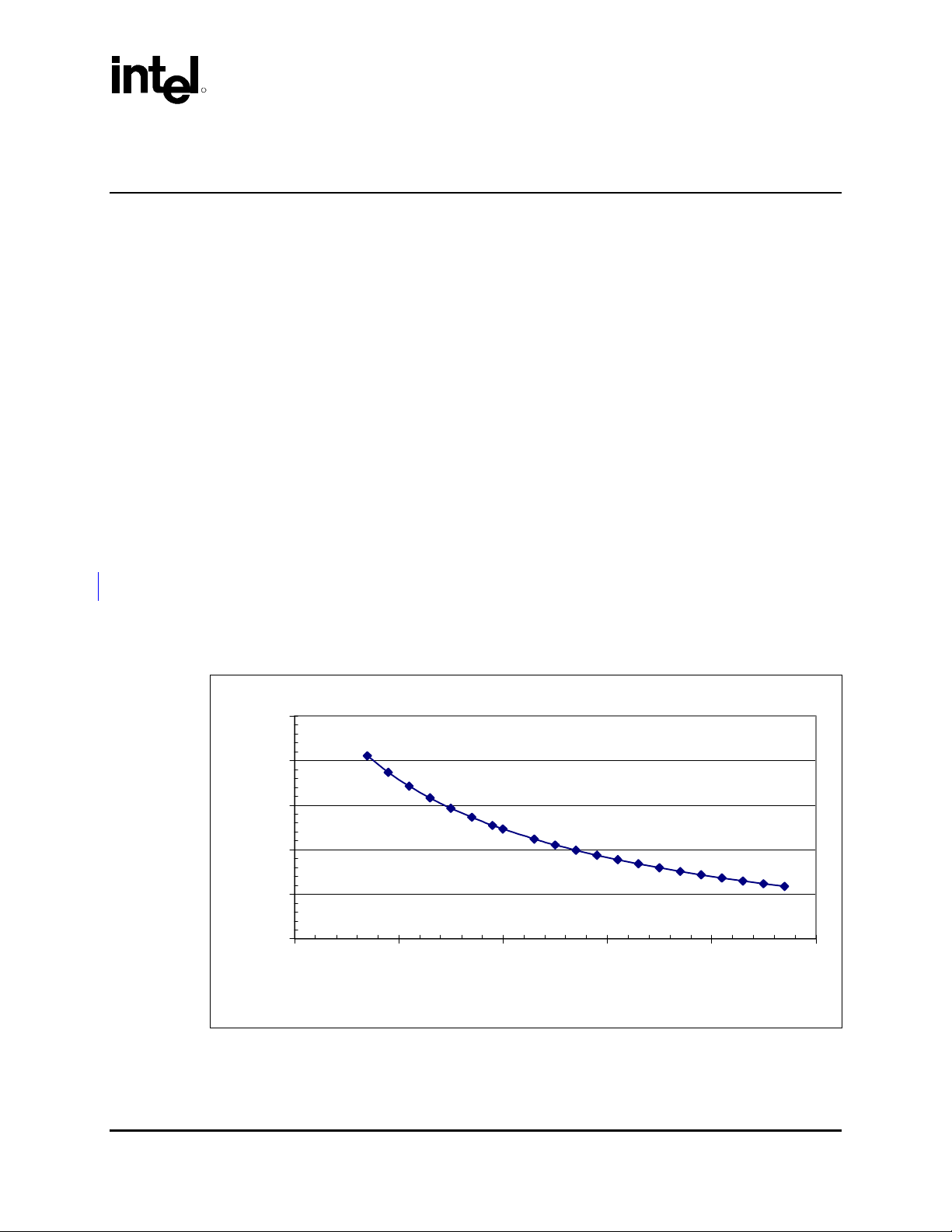
6.2 Heatsink Performance
Figure 6-1Figure 6-1Figure 6-1 depicts the measured thermal performance of the reference thermal
solution versus approach air velocity. Since this data was measured at sea level, a correction factor
would be required to estimate thermal performance at other altitudes.
Figure 6-1. Reference Heatsink Measured Thermal Performance Versus Approach Velocity
6.0
5.5
5.0
4.5
ca (°C/W)
4.0
3.5
50 100 150 200 250 300
Flow Rate (LFM)
®
Intel
6700PXH 64-bit PCI Hub Thermal/Mechanical Design Guidelines 17
Page 18

Reference Thermal SolutionReference Thermal SolutionReference Thermal Solution
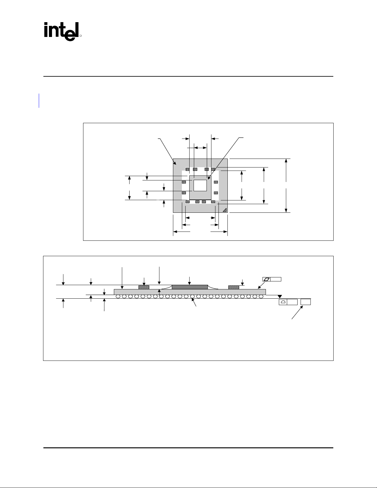
6.3 Mechanical Design Envelope
While each design may have unique mechanical volume and height restrictions or implementation
requirements, the height, width, and depth constraints typically placed on the PXH thermal solution
are shown in Figure 6-2Figure 6-2Figure 6-2.
When using heatsinks that extend beyond the PXH reference heatsink envelope shown in
Figure 6-2Figure 6-2Figure 6-2, any motherboard components placed between the heatsink and
motherboard cannot exceed 2.40 mm (0.094 in.) in height.
®
Figure 6-2. Torsional Clip Heatsink Volumetric Envelope for the Intel
Chipset Component
6700PXH 64-bit PCI Hub
R
3.01mm.
1.86mm.
FCBGA +
Solder Balls
Die + TIM
Heatsink Fin
Heatsink Base
Motherboard
31.00mm.
Heatsink
Fin
3.00mm.
31.00mm.
6.4 Board-Level Components Keepout Dimensions
The locations of hole pattern and keepout zones for the reference thermal solution are shown in
Figure 6-3Figure 6-3Figure 6-3 and Figure 6-4Figure 6-4Figure 6-4.
14.71mm
6.5 Torsional Clip Heatsink Thermal Solution Assembly
The reference thermal solution for the PXH component is a passive extruded heatsink with thermal
interface. It is attached using a clip with each end hooked through an anchor soldered to the board.
Figure 6-5Figure 6-5Figure 6-5 shows the reference thermal solution assembly and associated
components. Figure 6-6Figure 6-6Figure 6-6 shows the position of the heatsink rails relative to the
PXH package top surface.
Full mechanical drawings of the thermal solution assembly and the heatsink clip are provided in
Appendix B. Appendix A contains vendor information for each thermal solution component.
18
Intel® 6700PXH 64-bit PCI Hub Thermal/Mechanical Design Guidelines
Page 19

R
p
Reference Thermal SolutionReference Thermal SolutionReference Thermal Solution
Figure 6-3. Torsional Clip Heatsink Board Component Keepout
PXH
1.886
Parallel Mean
Airflow
Direction
Component
keepout area
1.756
2x 0.943
Max
component
Height 0.50
NOTE: All dimensions are in inches.
Figure 6-4. Retention Mechanism Component Keepout Zones
0.500
0.120
0.345
0.050"
Component
Keepout
0.345
0.173
Detail A
0.165
0.750
0.083
0.100
2x 0.038
Plated Through
0.200
0.170
Hole
2x 0.878
(0.165)
2x 0.060
Component
Keepout Area
0.225
See Detail
A
0.100
(0.345)
Component
out
Kee
2x 0.056
Trace
Keepout
NOTE: All dimensions are in inches.
Intel® 6700PXH 64-bit PCI Hub Thermal/Mechanical Design Guidelines 19
Page 20

Reference Thermal SolutionReference Thermal SolutionReference Thermal Solution
6.5.1 Heatsink Orientation
Since this solution is based on a unidirectional heatsink, mean airflow direction must be aligned
with the direction of the heatsink fins.
Figure 6-5. Torsional Clip Heatsink Assembly
R
Figure 6-6 Heatsink Rails to PXH Package Footprint
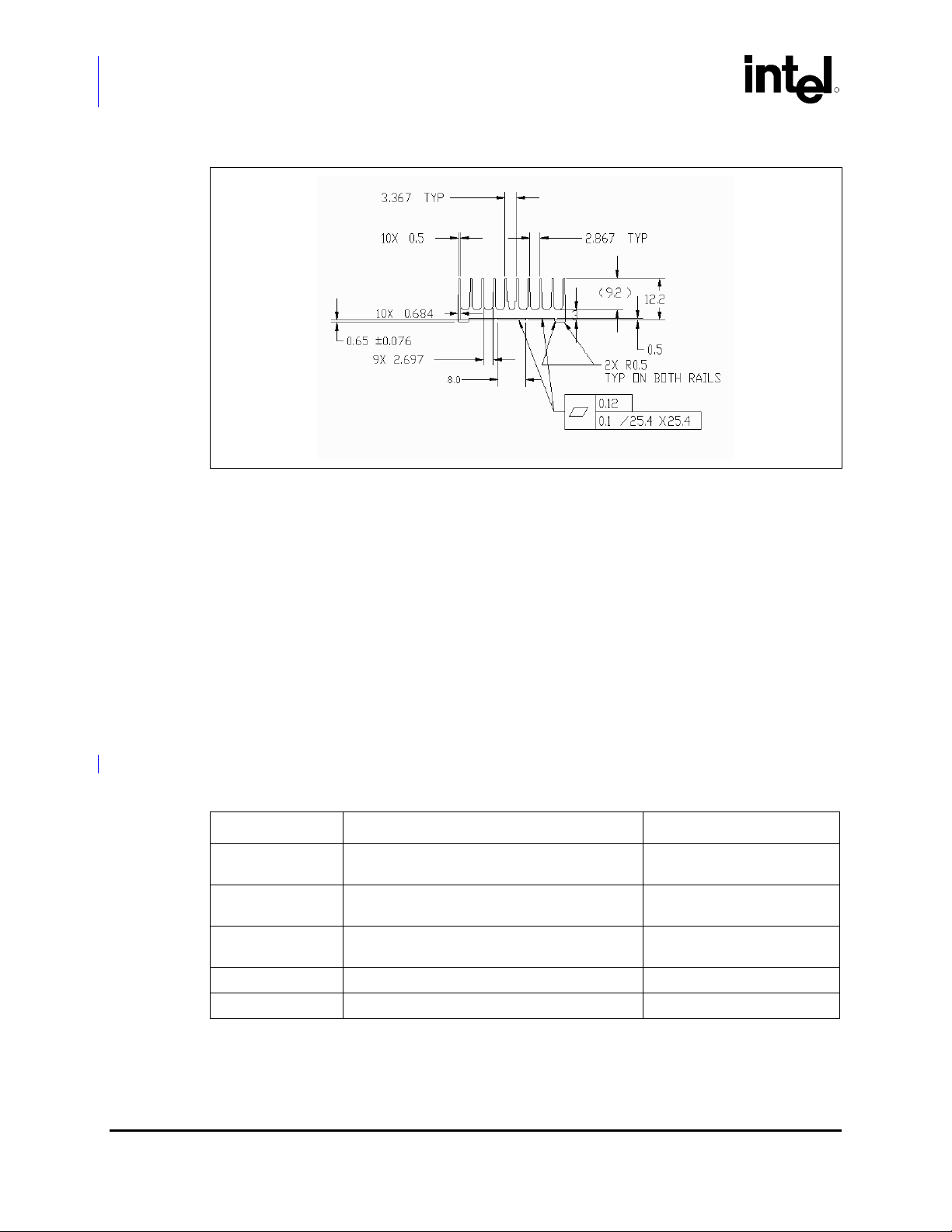
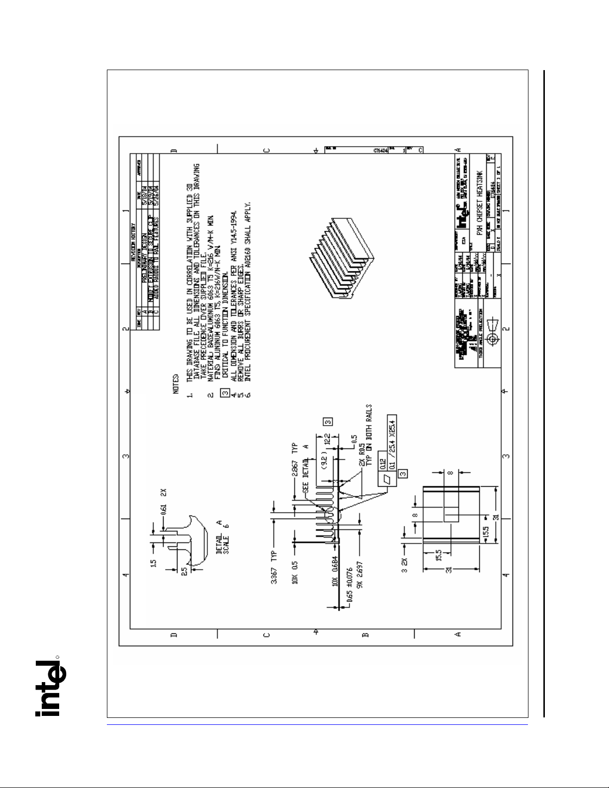
6.5.2 Extruded Heatsink Profiles
The reference torsional clip heatsink uses an extruded heatsink for cooling the PXH component.
Figure 6-7Figure 6-7Figure 6-7 shows the heatsink profile. Appendix A lists a supplier for this
extruded heatsink. Other heatsinks with similar dimensions and increased thermal performance may
be available. Full mechanical drawing of this heatsink is provided in Appendix B.
6.5.3 Mechanical Interface Material
There is no mechanical interface material associated with this reference solution.
20
Intel® 6700PXH 64-bit PCI Hub Thermal/Mechanical Design Guidelines
Page 21

R
Reference Thermal SolutionReference Thermal SolutionReference Thermal Solution
6.5.4 Thermal Interface Material
A thermal interface material provides improved conductivity between the die and heatsink. The
reference thermal solution uses Chomerics* T-710, 0.127 mm (0.005 in.) thick, 8 mm x 8 mm
square.
Note: Unflowed or “dry” Chomerics* T710 has a material thickness of 0.005 inch. The flowed or “wet”
Chromerics T710 has a material thickness of ~0.0025 inch after it reaches its phase change
temperature.
6.5.4.1 Effect of Pressure on TIM Performance
As mechanical pressure increases on the TIM, the thermal resistance of the TIM decreases. This
phenomenon is due to the decrease of the bond line thickness (BLT). BLT is the final settled
thickness of the thermal interface material after installation of heatsink. The effect of pressure on the
thermal resistance of the Chomerics T710 TIM is shown in Table 6-1Table 6-1Table 6-1. The
heatsink clip provides enough pressure for the TIM to achieve a thermal conductivity of 0.17°C
2
/W.
inch
Table 6-1. Chomerics* T710 TIM Performance as a Function of Attach Pressure
Pressure (psi) Thermal Resistance (°C × in2)/W
5 0.37
10 0.30
20 0.21
30 0.17
NOTE: All measured at 50°C.
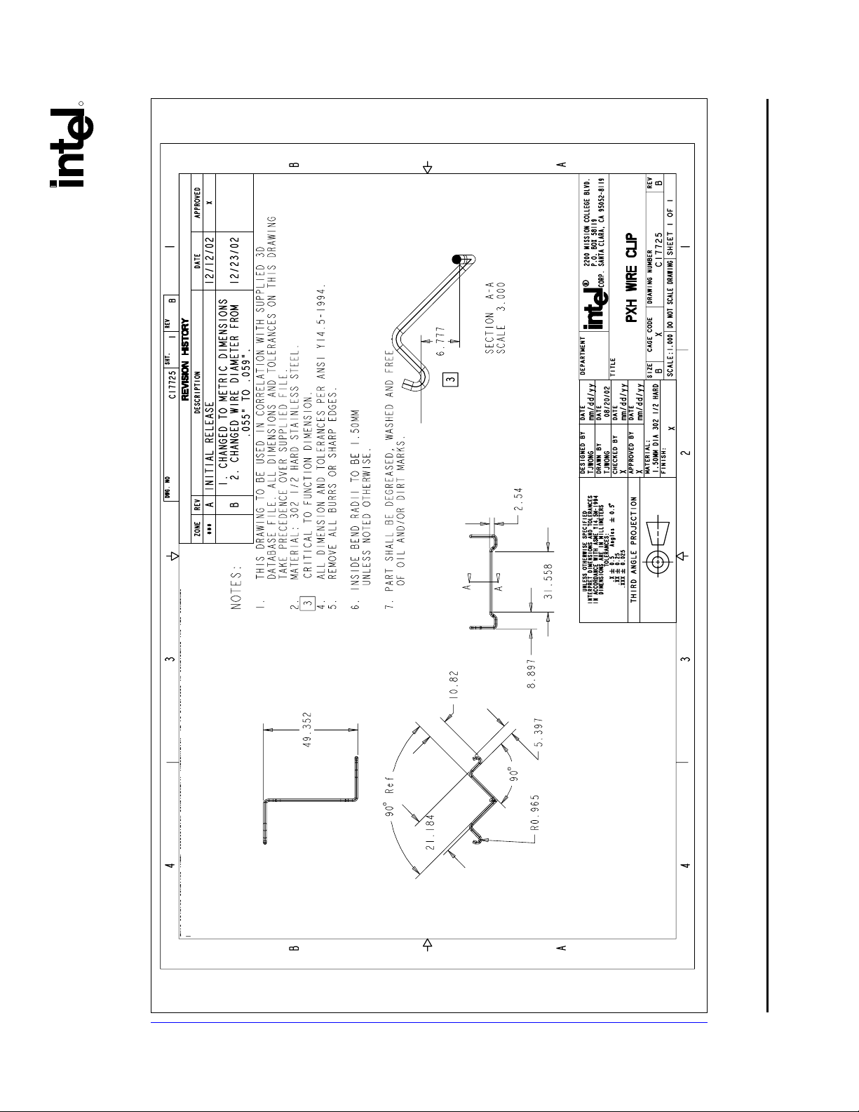
6.5.5 Heatsink Clip
The reference solution uses a wire clip with hooked ends. The hooks attach to wire anchors to fasten
the clip to the board. See Appendix B for a mechanical drawing of the clip.
Intel® 6700PXH 64-bit PCI Hub Thermal/Mechanical Design Guidelines 21
Page 22
Reference Thermal SolutionReference Thermal SolutionReference Thermal Solution
Figure 6-7. Torsional Clip Heatsink Extrusion Profile
6.5.6 Clip Retention Anchors
R
For Intel® 6700PXH 64-bit PCI Hub-based platforms that have very limited board space, a clip
retention anchor has been developed to minimize the impact of clip retention on the board. It is
based on a standard three-pin jumper and is soldered to the board like any common through-hole
header. A new anchor design is available with 45° bent leads to increase the anchor attach reliability
over time. See Appendix A for the part number and supplier information.
6.6 Reliability Guidelines
Each motherboard, heatsink and attach combination may vary the mechanical loading of the
component. Based on the end user environment, the user should define the appropriate reliability
test criteria and carefully evaluate the completed assembly prior to use in high volume. Some
general recommendations are shown in Table 6-2Table 6-2Table 6-2.
Table 6-2. Reliability Guidelines
(1)
Test
Requirement Pass/Fail Criteria
Mechanical Shock 50 g, board level, 11 msec, 3 shocks/axis.
Random Vibration 7.3 g, board level, 45 min/axis, 50 Hz to 2000 Hz.
Temperature Life
Thermal Cycling –5°C to +70°C, 500 cycles. Visual Check
Humidity 85% relative humidity, 55°C, 1000 hours. Visual Check
NOTES:
1. It is recommended that the above tests be performed on a sample size of at least twelve assemblies from
three lots of material.
2. Additional pass/fail criteria may be added at the discretion of the user.
85°C, 2000 hours total, checkpoints at 168, 500,
1000, and 2000 hours.
(2)
Visual Check and Electrical
Functional Test
Visual Check and Electrical
Functional Test
Visual Check
22
Intel® 6700PXH 64-bit PCI Hub Thermal/Mechanical Design Guidelines
Page 23

R
A Thermal Solution Component
Suppliers
A.1 Torsional Clip Heatsink Thermal Solution
Part Intel Part Number
Heatsink Assembly includes:
• Unidirectional Fin
Heatsink
• Thermal Interface
Material
• Torsional Clip
Undirectional Fin Heatsink
(31.0 x 31.0 x 12.2 mm)
Thermal Interface
(Chomerics* T-710)
Heatsink Attach Clip C17725-001 CCI/ACK
Solder-Down Anchor A13494-005
C76435-001 CCI/ACK*
C76434-001 CCI/ACK
A69230-001
Supplier
(Part Number)
Chomerics*
69-12-22066-T710
Foxconn*
(HB96030-DW)
Contact Information
Harry Lin (USA)
714-739-5797
hlinack@aol.com
Monica Chih (Taiwan)
866-2-29952666, x131
monica_chih@ccic.com.tw
Harry Lin (USA)
714-739-5797
hlinack@aol.com
Monica Chih (Taiwan)
866-2-29952666, x131
monica_chih@ccic.com.tw
Todd Sousa (USA)
360-606-8171
tsousa@parker.com
Harry Lin (USA)
714-739-5797
hlinack@aol.com
Monica Chih (Taiwan)
866-2-29952666, x131
monica_chih@ccic.com.tw
Julia Jiang (USA)
408-919-6178
juliaj@foxconn.com
Note: The enabled components may not be currently available from all suppliers. Contact the supplier
directly to verify time of component availability.
Intel® 6700PXH 64-bit PCI Hub Thermal/Mechanical Design Guidelines 23
Page 24

Thermal Solution Component Suppliers
R
24
Intel® 6700PXH 64-bit PCI Hub Thermal/Mechanical Design Guidelines
Page 25

R
B Mechanical Drawings
Table B-1Table B-1Table B-1 lists the mechanical drawings included in this appendix.
Table B-1. Mechanical Drawing List
Drawing Description Figure Number
Torsional Clip Heatsink Assembly Drawing
Torsional Clip Heatsink Drawing
Torsional Clip Drawing
Figure B-1Figure B-
1Figure B-1
Figure B-2Figure B-
2Figure B-2
Figure B-3Figure B-
3Figure B-3
Intel® 6700PXH 64-bit PCI Hub Thermal/Mechanical Design Guidelines 25
Page 26

R
6700PXH 64-bit PCI Hub Thermal/Mechanical Design Guidelines
®
Figure B-1. Torsional Clip Heatsink Assembly Drawing
Mechanical Drawings
26 Intel
Page 27
Mechanical Drawings
R
6700PXH 64-bit PCI Hub Thermal/Mechanical Design Guidelines 27
Figure B-2. Torsional Clip Heatsink Drawing
®
Intel
Page 28
R
§
6700PXH 64-bit PCI Hub Thermal/Mechanical Design Guidelines
®
Figure B-3.Torsional Clip Drawing
Mechanical Drawings
28 Intel
 Loading...