

Page 1

Intel® 5000 Series Chipset Memory
Controller Hub(MCH)
Thermal/Mechanical Design Guide
May 2006
Document Number: 313067-001
Page 2

INFORMATION IN THIS DOCUMENT IS PROVIDED IN CONNECTION WITH INTEL
TERMS AND CONDITIONS OF SALE FOR SU CH PRODUCTS, INTEL ASSUMES NO LIABILITY WHATSOEVER, AND INTEL DISCLAIMS
ANY EXPRESS OR IMPLIED WARRANTY RELATING TO SALE AND/OR USE OF INTEL PRODUCTS, INCLUDING LIABILITY OR
WARRANTIES RELATING TO FITNESS FOR A PARTICULAR PURPOSE, MERCHANTABILITY, OR INFRINGEMENT OF ANY PATENT,
COPYRIGHT, OR OTHER INTELLECTUAL PROPERTY RIGHT.
Intel may make changes to specifications, product descriptions, and plans at any time, without notice.
Designers must not rely on the absence or characteristics of any features or instructions marked “reserved” or “undefined.” Intel
reserves these for future definition and shall have no responsibility whatsoever for con f licts or incompatibilities arising from future
changes to them.
The Intel® 5000 Series chipset Memory Controller Hub may contain design defects or errors known as errata, which may cause the
product to deviate from published specifications. Current characterized errata are available upon request.
Contact your local Intel sales office or your distributor to obtain the latest specifications and before placing your product order.
Copies of documents which have an order number and are referenced in this document, or other Intel literature, may be obtained
by calling 1-800-548-4725, or by visiting Intel’s website at http://www.intel.com
Intel and The Dual-Core Intel® Xeon® processor 5000 Sequence, the Intel® 6700PXH 64-bit PCI Hub, the Intel®
E7500/E7501/E7505 chipset
registered trademarks of Intel Corporation or its subsidiaries in the United States and other countries.
Copyright © 2006, Intel Corporation. All rights reserved.
* Other brands and names may be claimed as the property of others.
2 Intel® 5000 Series Chipset Memory Controller Hub (MCH) Thermal Mechanical Design Guide
and the Intel® 631xESB/632xESB I/O Controller Hub and the Intel logo are a trademarks or
®
PRODUCTS. EXCEPT AS PROVIDED IN INTEL’S
.
Page 3

Contents
1Introduction..............................................................................................................7
1.1 Design Flow........................................................................................................7
1.2 Definition of Terms..............................................................................................8
1.3 Reference Documents......................... ........................... ... ........................... ........9
2 Packaging Technology.............................................................................................11
2.1 Package Mechanical Requirements................................................ .......................12
3 Thermal Specifications ............................................................................................13
3.1 Thermal Design Power (TDP) ..............................................................................13
3.2 Case Temperature.................................... .. ... ........................... .. .......................13
4 Thermal Simulation ................................................................................................. 15
5 Thermal Metrology ..................................................................................................17
5.1 MCH Case Temperature Measurement..................................................................17
5.1.1 Supporting Test Equipment......................................................................17
5.1.2 Thermal Calibration and Controls..............................................................18
5.1.3 IHS Groove ...........................................................................................18
5.1.4 Thermocouple Conditioning and Preparation...............................................19
5.1.5 Thermocouple Attachment to the IHS........................................................20
5.1.6 Curing Process.......................................................................................23
5.1.7 Thermocouple Wire Management..............................................................24
5.1.8 Power Simulation Software......................................................................25
6 Reference Thermal Solution.....................................................................................27
6.1 Operating Environment.......................................... .. .. .. ......................................27
6.2 Heatsink Performance........................................................................................27
6.3 Mechanical Design Envelope ...............................................................................28
6.4 Board-Level Components Keepout Dimensions ........................... .. .. .. .....................28
6.5 Tall Torsional Clip Heatsink Thermal Solution Assembly ..........................................29
6.5.1 Heatsink Orientation...............................................................................30
6.5.2 Extruded Heatsink Profiles.......................................................................31
6.5.3 Mechanical Interface Material...................................................................31
6.5.4 Thermal Interface Material.......................................................................31
6.5.5 Heatsink Clip .........................................................................................31
6.5.6 Clip Retention Anchors............................................................................32
6.6 Reliability Guidelines.......................................................................................... 32
7 Reference Thermal Solution 2..................................................................................35
7.1 Operating Environment.......................................... .. .. .. ......................................35
7.2 Heatsink Performance........................................................................................35
7.3 Mechanical Design Envelope ...............................................................................36
7.4 Board-Level Components Keepout Dimensions ........................... .. .. .. .....................36
7.5 Short Torsional Clip Heatsink Thermal Solution Assembly........................................37
7.5.1 Heatsink Orientation...............................................................................38
7.5.2 Extruded Heatsink Profiles.......................................................................39
7.5.3 Mechanical Interface Material...................................................................39
7.5.4 Thermal Interface Material.......................................................................39
7.5.5 Clip Retention Anchors............................................................................39
7.6 Reliability Guidelines.......................................................................................... 39
Intel® 5000 Series Chipset Memory Controller Hub (MCH) Thermal Mechanical Design Guide 3
Page 4

A Thermal Solution Component Suppliers....................................................................41
A.1 Tall Torsional Clip Heatsink Thermal Solution.........................................................41
A.2 Short Torsional Clip Heatsink Thermal Solution......................................................42
B Mechanical Drawings ...............................................................................................43
Figures
1-1 Thermal Design Process................................................................... .................... 8
2-1 MCH Package Dimensions (Top View)...................................................................11
2-2 MCH Package Dimensions (Side View) ..................................................................11
2-3 MCH Package Dimensions (Bottom View)..............................................................12
5-1 IHS Groove Dimensions......................................................................................19
5-2 Orientation of Thermocouple Groove Relative to Package Pin...................................19
5-3 Bending the Tip of the Thermocouple....................................................................20
5-4 Securing Thermocouple Wires with Kanton* Tape Prior to Attach..............................21
5-5 Thermocouple Bead Placement............................................................................21
5-6 Position Bead on the Groove Step........................................................................22
5-7 Using 3D Micromanipulator to Secure Bead Location...............................................22
5-8 Measuring Resistance between Thermocouple and IHS............................................22
5-9 Applying the Adhesive on the Thermocouple Bead..................................................23
5-10 Thermocouple Wire Management Groove ..............................................................24
5-11 Removing Excess Adhesive from the IHS ..............................................................24
5-12 Filling the Groove with Adhesive ..........................................................................24
6-1 Tall Torsional Clip Heatsink Measured Thermal
Performance Versus Approach Velocity .................................................................27
6-2 Tall Torsional Clip Heatsink Volumetric Envelope for the Chipset MCH .......................28
6-3 Tall Torsional Clip Heatsink Board Component Keepout...........................................29
6-4 Retention Mechanism Component Keepout Zones...................................................30
6-5 Tall Torsional Clip Heatsink Assembly ...................................................................30
6-6 Tall Torsional Clip Heatsink Extrusion Profile..........................................................32
7-1 Short Torsional Clip Heatsink Measured
Thermal Performance Versus Approach Velocity.....................................................35
7-2 Short Torsional Clip Heatsink Volumetric Envelope for the Chipset MCH.....................36
7-3 Short Torsional Clip Heatsink Board Component Keepout ........................................37
7-4 Retention Mechanism Component Keepout Zones...................................................38
7-5 Short Torsional Clip Heatsink Assembly.................................................................38
7-6 Torsional Clip Heatsink Extrusion Profile................................................................39
B-1 Tall Torsional Clip Heatsink Assembly Drawing.......................................................44
B-2 Tall Torsional Clip Heatsink Drawing (Sheet 1 of 2).................................................45
B-3 Tall Torsional Clip Heatsink Drawing (Sheet 2 of 2).................................................46
B-4 Tall Torsional Clip Heatsink Clip Drawing...............................................................47
B-5 Short Torsional Clip Heatsink Assembly Drawing ....................................................48
B-6 Short Torsional Clip Heatsink Drawing(Sheet 1 of 2)......................................... .. ....49
B-7 Short Torsional Clip Heatsink Drawing(Sheet 2 of 2)......................................... .. ....50
B-8 Short Torsional Clip Heatsink Clip Drawing............................................................51
4 Intel® 5000 Series Chipset Memory Controller Hub (MCH) Thermal Mechanical Design Guide
Page 5

Tables
3-1 Intel® 5000P Chipset MCH Thermal Specifications........ ......................................... 13
3-2 Intel® 5000V Chipset MCH Thermal Specifications................................................. 13
3-3 Intel® 5000X Chipset MCH Thermal Specifications................................................. 14
5-1 Thermocouple Attach Support Equipment.............................................................17
6-1 Honeywell PCM45 F TIM Performance as a Function of Attach Pressure .....................31
6-2 Reliability Guidelines.......................................................................................... 32
B-1 Mechanical Drawing List .....................................................................................43
Intel® 5000 Series Chipset Memory Controller Hub (MCH) Thermal Mechanical Design Guide 5
Page 6

Revision Table
Revision
Number
-001 Initial release of the document. May 2006
Description Date
§§
6 Intel® 5000 Series Chipset Memory Controller Hub (MCH) Thermal Mechanical Design Guide
Page 7

Introduction
1 Introduction
As the complexity of computer systems increases, so do the power dissipation
requirements. Care must be taken to ensure that the additional power is properly
dissipated. Typical methods to improve heat dissipation include selective use of
ducting, and/or passive heatsinks.
The goals of this document are to:
• Outline the thermal and mechanical operating limits and specifications for the
• Describe reference thermal solutions that meet the specification of the
Properly designed thermal solutions provide adequate cooling to maintain the
Intel 5000 Series chipset MCH die temperatures at or below thermal specifications. This
is accomplished by providing a low local-ambient temperature, ensuring adequate local
airflow, and minimizing the die to local-ambient thermal resistance. By maintaining the
Intel 5000 Series chipset MCH die temperature at or below the specified limits, a
system designer can ensure the proper functionality, performance, and reliability of the
chipset. Operation outside the functional limits can degrade system performance and
may cause permanent changes in the operating characteristics of the component.
®
5000 Series chipset memory controller hub (MCH).
Intel
Intel 5000 Series chipset MCH.
The simplest and most cost effective method to improve the inherent system cooling
characteristics is through careful chassis design and placement of fans, vents, and
ducts. When additional cooling is required, component thermal solutions may be
implemented in conjunction with system thermal solutions. The size of the fan or
heatsink can be varied to balance size and space constraints with acoustic noise.
This document addresses thermal design and specifications for the
Intel 5000 Series chipset MCH components only. For thermal design information on
other chipset components, refer to the respective component datasheet. For the PXH,
refer to the Intel
the Intel
I/O Controller Hub Thermal/Mechanical Design Guidelines.
Note: Unless otherwise specified, the term “MCH” refers to the Intel 5000 Series chipset MCH.
®
®
6700PXH 64-bit PCI Hub Thermal/Mechanical Design Guidelines. For
631xESB/632xESB I/O Controller Hub, refer to the Intel® 631xESB/632xESB
1.1 Design Flow
To develop a reliable, cost-effective thermal solution, several tools have been provided
to the system designer. Figure 1-1 illustrates the design process implicit to this
document and the tools appropriate for each step.
Intel® 5000 Series Chipset Memory Controller Hub (MCH) Thermal Mechanical Design Guide 7
Page 8
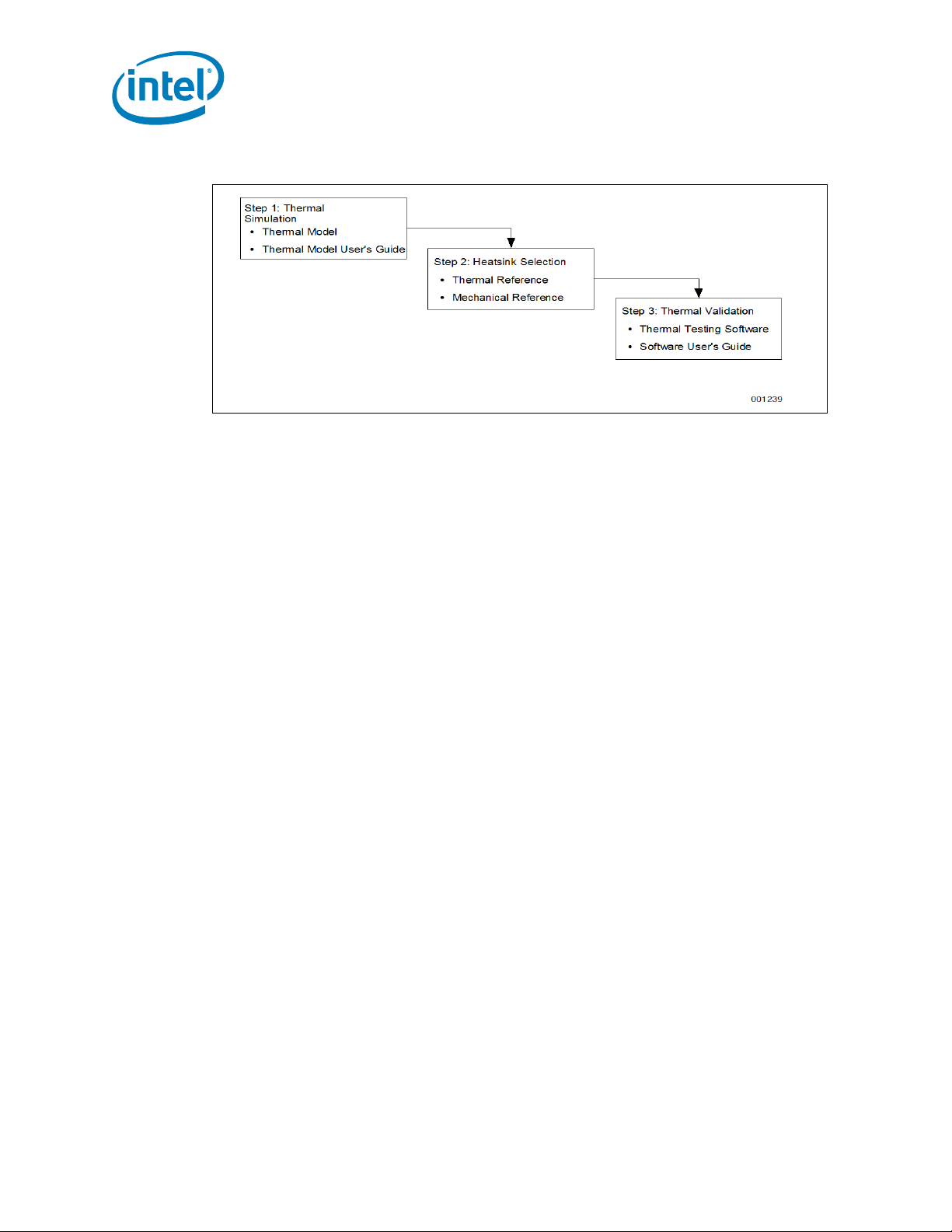
Figure 1-1. Thermal Design Process
1.2 Definition of Terms
BGA Ball grid array. A package type, defined by a resin-fiber
substrate, onto which a die is mounted, bonded and
encapsulated in molding compound. The primary electrical
interface is an array of solder balls attached to the substrate
opposite the die and
molding compound.
BLT Bond line thickness. Final settled thickness of the thermal
interface material after installation of heatsink.
®
Intel
631xESB/632xESB I/O Controller Hub
The chipset component that integrates an Ultra ATA 100
controller, six Serial ATA host controller ports, one EHCI host
controller, and four UHCI host controllers supporting eight
external USB 2.0 ports, LPC interface controller, flash BIOS
interface controller, PCI interface controller, Azalia / AC’97
digital controller, integrated LAN controller, an ASF controller
and a ESI for communication with the MCH. The Intel 631xESB/
632xESB I/O Controller Hub component provides the data
buffering and interface arbitration required to ensure that
system interfaces operate efficiently and provide the bandwidth
necessary to enable the system to obtain peak performance.
MCH Memory controller hub. The chipset component that contains
PXH Intel
PXH-V Intel
T
case_max
the processor interface, the memory interface, the PCI Express*
interface and the ESI interface.
®
6700PXH 64-bit PCI Hub. The chipset component that
performs PCI bridging functions between the PCI Express
interface and the PCI Bus. It contains two PCI bus interfaces
that can be independently configured to operate in PCI (33 or 66
MHz) or PCI-X* mode 1 (66, 100 or 133 MHz), for either 32 or
64 bit PCI devices.
®
6702PXH 64-bit PCI Hub. The chipset component that
performs PCI bridging functions between the PCI Express
interface and the PCI Bus. It contains one PCI bus interface that
can be configured to operate in PCI (33 or 66MHz) or PCI-X
mode 1 (66, 100 or 133 MHz).
Maximum IHS temperature allowed. This temperature is
measured at the geometric center of the top of IHS.
Introduction
8 Intel® 5000 Series Chipset Memory Controller Hub (MCH) Thermal Mechanical Design Guide
Page 9

Introduction
T
case_min
Minimum IHS temperature allowed. This temperature is
measured at the geometric center of the top of IHS.
TDP Thermal design power. Thermal solutions should be designed to
dissipate this target power level. TDP is not the maximum power
that the chipset can dissipate.
1.3 Reference Documents
The reader of this specification should also be familiar with material and concepts
presented in the following documents:
•Intel® 6700PXH 64-bit PCI Hub Thermal/Mechanical Design Guide
•Intel® 6700PXH 64-bit PCI Hub Datasheet
•Intel
•Intel® 5000P/5000V/5000Z Chipset Memory Controller Hub (MCH) Datasheet
•Intel® 5000X Chipset Memory Controller Hub (MCH) Datasheet
• Dual-Core Intel® Xeon® Processor 5000 Series Datasheet
• Dual-Core Intel
• BGA/OLGA Assembly Development Guide
• Various system thermal design suggestions (http://www.formfactors.org)
®
631xESB/632xESB I/O Controller Hub Thermal/Mechanical Design
Guidelines
®
Xeon® Processor 5000 Series Thermal/Mechanical Design
Guidelines
Note: Unless otherwise specified, these documents are available through your Intel field sales
representative. Some documents may not be available at this time.
§§
Intel® 5000 Series Chipset Memory Controller Hub (MCH) Thermal Mechanical Design Guide 9
Page 10

Introduction
10 Intel® 5000 Series Chipset Memory Controller Hub (MCH) Thermal Mechanical Design Guide
Page 11
Packaging Technology
2 Packaging Technology
Intel 5000 Series chipset consist of three individual components: the Memory
Controller Hub (MCH), the Intel
®
6700PXH 64-bit PCI Hub (PXH) and the Intel®
631xESB/632xESB I/O Controller Hub. Intel 5000 Series chipset MCH components use
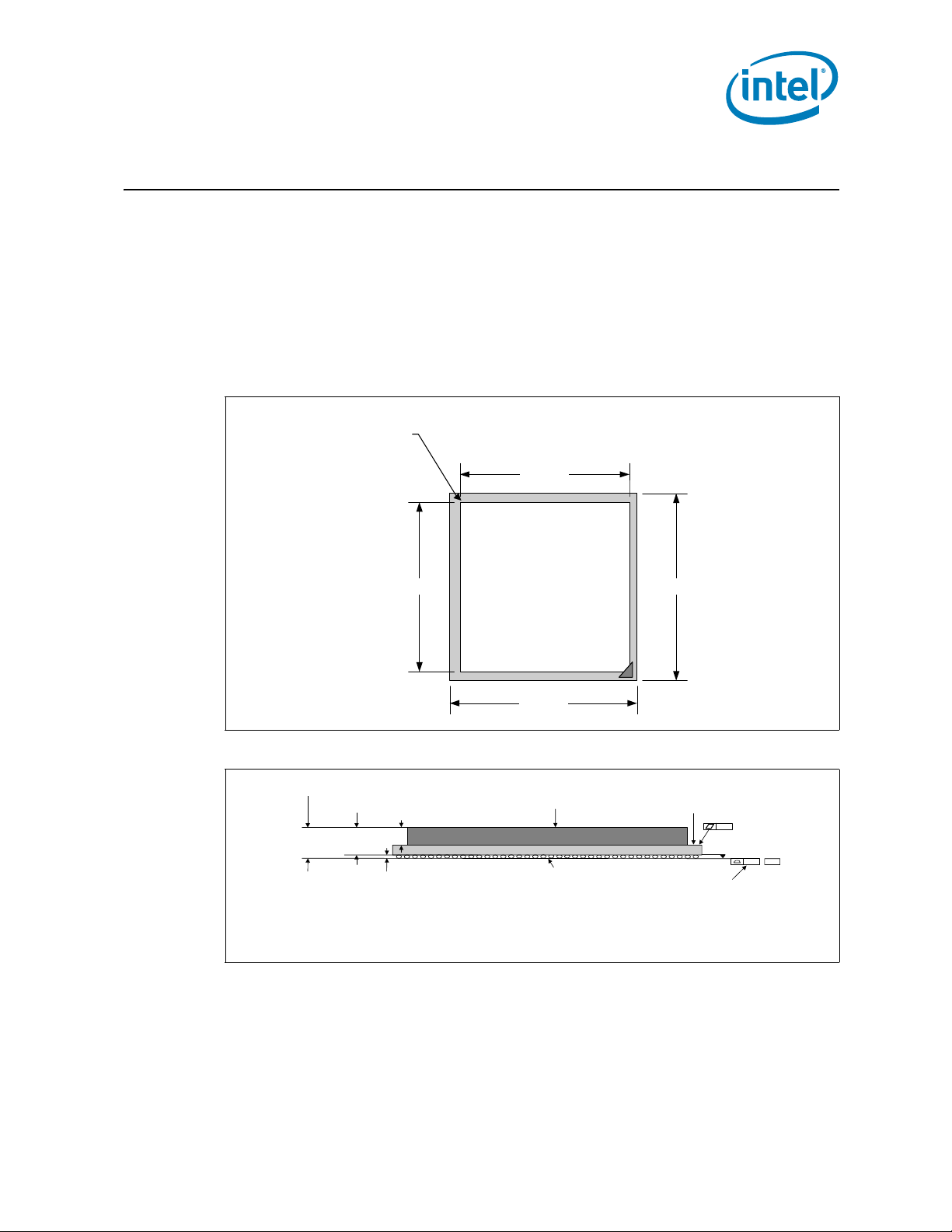
a 42.5 mm, 10-layer flip chip ball grid array (FC-BGA) package (see Figure 2-1, , and
Figure 2-2). For information on the PXH package, refer to the Intel
PCI Hub Thermal/Mechanical Design Guidelines. For information on the Intel
631xESB/632xESB I/O Controller Hub package, refer to the Intel
I/O Controller Hub Thermal/Mechanical Design Guidelines.
Figure 2-1. MCH Package Dimensions (Top View)
Handling
Exclusion
Area
38.5 mm,
MCH
IHS
®
6700PXH 64-bit
®
631xESB/632xESB
42.5 mm.38.5 mm.
®
Figure 2-2. MCH Package Dimensions (Side View)
4.23 ± 0.146 mm
3.79 ± 0.144 mm
Notes:
1. Primary datum -C- and seating plan are def ine d by t he spherical crowns of the solder balls (shown before motherboard attach)
2. All dimensions and tolerances conform to ANS I Y 14.5M-1994
3. BGA has a pre-SMT height of 0.5mm and post-SMT height of 0.41-0.46mm
4. Shown before motherboard atta ch; FCBGA has a convex (dome shaped) orientation bef or e reflow and is expected to have a slightly concave (bowl shaped)
orientation after reflow
2.44 ± 0.071 mm
0.435 ± 0.025 mm
See note 3
42.5 mm.
IHS
Seating Plane
Substrate
0.20
See note 1.
See note 4.
0.20 –C–
Intel® 631xESB/632xESB I/O Controller Hub Thermal Mechanical Design Guide 11
Page 12
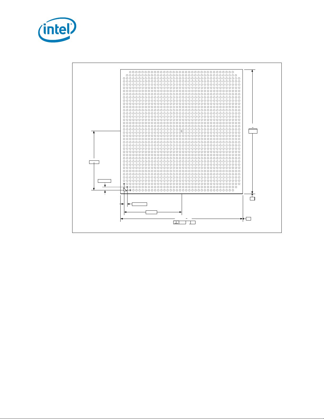
Figure 2-3. MCH Package Dimensions (Bottom View)
AV
AU
AT
AR
AP
AN
AM
AL
AK
AJ
AH
AG
AF
AE
AD
AC
AB
AA
Y
W
V
U
T
R
P
N
M
20.202
37X 1.092
L
K
J
H
G
F
E
D
C
B
A
37X
1.092
11 252321191715139753127293733 3531
20.202
42.5 +
0.05
0.
2
C A
Packaging Technology
2822 26242018161412108642 36343230 38
42.5 + 0.05
- A
-
A
B
Notes:
1. All dimensions are in millimeters.
2. All dimensions and tolerances conform to ANSI Y14.5M-1994.
2.1 Package Mechanical Requirements
The Intel 5000 Series chipset MCH package has an integrated heat spreader (IHS) that
is capable of sustaining a maximum static normal load of 15 lbf. These mechanical load
limits must not be exceeded during heatsink installation, mechanical stress testing,
standard shipping conditions and/or any other use condition.
Note:
1. The heatsink attach solutions must not include continuous stress to the chipset
package with the exception of a uniform load to maintain the heatsink-to-package
thermal interface.
2. These specifications apply to uniform compressive loading in a direction
perpendicular to the IHS top surface.
3. These specifications are based on limited testing for design characterization.
Loading limits are for the package only.
§
12 Intel® 631xESB/632xESB I/O Controller Hub Thermal Mechanical Design Guide
Page 13
Thermal Specifications
3 Thermal Specifications
3.1 Thermal Design Power (TDP)
Analysis indicates that real applications are unlikely to cause the MCH component to
consume maximum power dissipation for sustained time periods. Therefore, in order to
arrive at a more realistic power level for thermal design purposes, Intel characterizes
power consumption based on known platform benchmark applications. The resulting
power consumption is referred to as the Thermal Design Power (TDP). TDP is the target
power level to which the thermal solutions should be designed. TDP is not the
maximum power that the chipset can dissipate.
®
For TDP specifications, see Table 3-1 for the Intel
the Intel
®
5000V chipset MCH, and Table 3-3 for the Intel® 5000X chipset MCH. FCBGA packages have poor heat transfer capability into the board and have minimal
thermal capability without thermal solution. Intel recommends that system designers
plan for a heatsink when using Intel 5000 Series chipset.
3.2 Case Temperature
5000P chipset MCH, Table 3-2 for
To ensure proper operation and reliability of the Intel 5000 Series chipset MCH, the
case temperatures must be at or between the maximum/minimum operating
temperature ranges as specified in Table 3-1 through Table 3-3. System and/or
component level thermal solutions are required to maintain these temperature
specifications. Refer to Chapter 5, “Thermal Metrology” for guidelines on accurately
measuring package case temperatures.
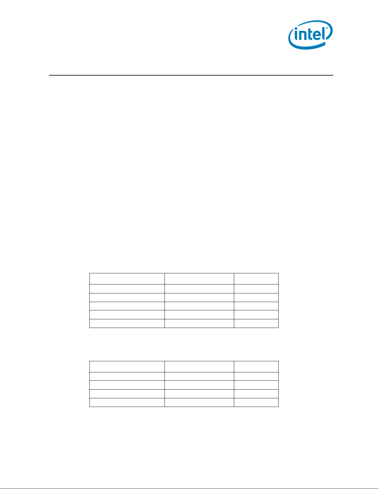
Table 3-1. Intel® 5000P Chipset MCH Thermal Specifications
Parameter Value Notes
T
case_max
T
case_min
TDP
with 1 active memory channel
TDP
with 2 active memory channel
TDP
with 4 active memory channel
105°C
5°C
24.7 W
26.4 W
30.0 W
Note: These specifications are based on preliminary silicon characterization, however, they
may be updated as further data becomes available.
Table 3-2. Intel® 5000V Chip set MCH Thermal Specifications
Parameter Value Notes
T
case_max
T
case_min
TDP
with 1 active memory channel
TDP
with 2 active memory channel
105°C
5°C
23.4 W
25.1 W
Note: These specifications are based on preliminary silicon characterization; however, they
may be updated as further data becomes available.
Intel® 631xESB/632xESB I/O Controller Hub Thermal Mechanical Design Guide 13
Page 14

Table 3-3. Intel® 5000X Chipset MCH Thermal Specifications
Parameter Value Notes
T
case_max
T
case_min
TDP
with 1 active memory channel
TDP
with 2 active memory channel
TDP
with 4 active memory channel
105°C
5°C
27.3 W
29.0 W
32.4 W
Thermal Specifications
Note: These specifications are based on preliminary silicon characterization, however, they
may be updated as further data becomes available.
§
14 Intel® 631xESB/632xESB I/O Controller Hub Thermal Mechanical Design Guide
Page 15

Thermal Simulation
4 Thermal Simulation
Intel provides thermal simulation models of the Intel 5000 Series chipset MCH and
associated user’s guides to aid system designers in simulating, analyzing, and
optimizing their thermal solutions in an integrated, system-level environment. The
models are for use with the commercially available Computational Fluid Dynamics
(CFD)-based thermal analysis tool FLOTHERM* (version 5.1 or higher) by Flomerics,
Inc. Contact your Intel field sales representative to order the thermal models and
user’s guides.
§
Intel® 631xESB/632xESB I/O Controller Hub Thermal Mechanical Design Guide 15
Page 16

Thermal Simulation
16 Intel® 631xESB/632xESB I/O Controller Hub Thermal Mechanical Design Guide
Page 17

Thermal Metrology
5 Thermal Metrology
The system designer must make temperature measurements to accurately determine
the thermal performance of the system. Intel has established guidelines for proper
techniques to measure the MCH case temperatures. Section 5.1 provides guidelines on
how to accurately measure the MCH case temperatures. Section 5.1.8 contains
information on running an application program that will emulate anticipated maximum
thermal design power (Figure 5-1).
5.1 MCH Case Temperature Measurement
Intel 5000 Series chipset MCH cooling performance is determined by measuring the
case temperature using a thermocouple. For case temperature measurements, the
attached method outlined in this section is recommended for mounting a
thermocouple.
Special care is required when measuring case temperature (T
temperature measurement. Thermocouples are often used to measure T
measuring the temperature of a surface that is at a different temperature from the
surrounding local ambient air, errors may be introduced in the measurements. The
measurement errors can be caused by poor thermal contact between the thermocouple
junction and the surface of the integrated heat spreader, heat loss by radiation,
convection, by conduction through thermocouple leads, or by contact between the
thermocouple cement and the heatsink base. To minimize these measurement errors,
the approach outlined in the next section is recommended.
5.1.1 Supporting Test Equipment
T o apply the reference thermocouple attach procedure, it is recommended that you use
the equipment (or equivalent) given in. Table 5-1.
Table 5-1. Thermocouple Attach Support Equipment (Sheet 1 of 2)
Item Description Part Number
Measurement and Output
Microscope Olympus Light microscope or equivalent SZ-40
Digital Multi-m
Micromanipulator*
(See note)
Super Bonder* 498
Thermal Cycling
Resistant Instant
Adhesive
Adhesive Accelerator Loctite 7452* for fast glue curing 18490
Kapton Tape For holding thermocouple in place or equivalent Not Available
Thermocouple Omega, 36 gauge, “T” Type 5SRTC-TT-36-72
eter Digital Multi Meter for resistance measurement Not Available
Test Fixture(s)
Micromanipulator set from YOU Ltd. or equivalent Mechanical
3D arm with needle (not included) to maintain TC bead location
during the attach process.
Miscellaneous Hardware
Super glue w/thermal characteristics 49850
) to ensure an accurate
C
. When
C
YOU-3
Intel® 631xESB/632xESB I/O Controller Hub Thermal Mechanical Design Guide 17
Page 18

Table 5-1. Thermocouple Attach Support Equipment (Sheet 2 of 2)
Item Description Part Number
Calibration and Control
Ice Point* Cell Omega, stable 0°C temperature source for calibration and
Hot Point* Cell Omega, temperature source to control and understand meter
Note:
1. Three axes set consists of (1ea. U-31CF), (1ea. UX-6-6), (1ea. USM6) and (1ea. UPN-1). More information
available at: http://www.narishige.co.jp/you_ltd/english/products/set/you-set.htm#3.
offset
slope gain
5.1.2 Thermal Calibration and Controls
It is recommended that full and routine calibration of temperature measurement
equipment be performed before attempting to perform temperature case measurement
of the Intel 5000 Series chipset MCH. Intel recommends checking the meter probe set
against known standards. This should be done at 0ºC (using ice bath or other stable
temperature source) and at an elevated temperature, around 80ºC (using an
appropriate temperature source).
Wire gauge and length also should be considered as some less expensive measurement
systems are heavily impacted by impedance. There are numerous resources available
throughout the industry to assist with implementation of proper controls for thermal
measurements.
Thermal Metrology
TRCIII
CL950-A-110
Note:
1. It is recommended to follow company standard procedures and wear safety items
like glasses for cutting the IHS and gloves for chemical handling.
2. Ask your Intel field sales representative if you need assistance to groove and/or
install a thermocouple according to the reference process.
5.1.3 IHS Groove
Cut a groove in the package IHS according to the drawing given in. Figure 5-1.
18 Intel® 631xESB/632xESB I/O Controller Hub Thermal Mechanical Design Guide
Page 19

Thermal Metrology
Figure 5-1. IHS Groove Dimensions
Figure 5-2. Orientation of Thermocouple Groove Relative to Package Pin
5.1.4 Thermocouple Conditioning and Preparation
1. Use a calibrated thermocouple as specified in Table 5-1.
2. Measure the thermocouple resistance by holding both wires on one probe and the
tip of thermocouple to the other probe of the DMM (compare to thermocouple
resistance specifications).
3. Straighten the wire for about 38 mm (1½ inch) from the bead to place it inside the
channel.
4. Bend the tip of the thermocouple to approximately a 45 degree angle by 0.8 mm
(0.030 inch) from the tip (Figure 5-3).
Intel® 631xESB/632xESB I/O Controller Hub Thermal Mechanical Design Guide 19
Page 20

Thermal Metrology
Figure 5-3. Bending the Tip of the Thermocouple
5.1.5 Thermocouple Attachment to the IHS
Caution: To avoid the impact on the thermocouple during the SMT process, reflow must be
performed before attaching the thermocouple to the grooved MCH IHS.
1. Clean the thermocouple wire groove with isopropyl alcohol (IPA) and a lint free
cloth removing all residues prior to thermocouple attachment.
2. Place the thermocouple wire inside the groove letting the exposed wire and bead
extend about 3.2 mm (0.125 inch) past the end of groove. Secure it with Kapton
tape (Figure 5-4).
3. Lift the wire at the middle of groove with tweezers and bend the front of wire to
place the thermocouple in the channel ensuring the tip is in contact with the end of
the channel grooved in the IHS (Figure 5-5 A and B).
4. Place the MCH under the microscope unit (similar to the one used in Figure 5-8) to
continue with process. It is also recommended to use a fixture to help holding the
unit in place for the rest of the attach process.
5. Press the wire down about 6 mm (0.125 in.) from the thermocouple bead using the
tweezers. Look in the microscope to perform this task. Place a piece of Kapton tape
to hold the wire inside the groove (Figure 5-7). Refer to Figure 5-6 for detailed
bead placement.
6. Using the micromanipulator, place the needle near to the end of groove on top of
thermocouple. Using the X, Y, and Z axes on the arm, places the tip of needle on
top of the thermocouple bead. Press down until the bead is seated at the end of
groove on top of the step (see Figure 5-6 and Figure 5-7).
7. Measure resistance from thermocouple end wires (hold both wires to a DMM probe)
to the IHS surface. This should be the same value as measured during the
thermocouple conditioning see “Thermocouple Conditioning and Preparation” on
page 19, step 2 and Figure 5-8.
8. Place a small amount of Loctite 498* adhesive in the groove where the bead is
installed. Using a fine point device, spread the adhesive in the groove around the
needle, the thermocouple bead and the thermocouple wires already installed in the
groove during step 5. Be careful not to move the thermocouple bead during this
step (Figure 5-9).
20 Intel® 631xESB/632xESB I/O Controller Hub Thermal Mechanical Design Guide
Page 21

Thermal Metrology
Figure 5-4. Securing Thermocouple Wires with Kanton* Tape Prior to Attach
Figure 5-5. Thermocouple Bead Placement
Intel® 631xESB/632xESB I/O Controller Hub Thermal Mechanical Design Guide 21
Page 22

Figure 5-6. Position Bead on the Groove Step
Figure 5-7. Using 3D Micromanipulator to Secure Bead Location
Thermal Metrology
Figure 5-8. Measuring Resistance between Thermocouple and IHS
22 Intel® 631xESB/632xESB I/O Controller Hub Thermal Mechanical Design Guide
Page 23

Thermal Metrology
Figure 5-9. Applying the Adhesive on the Thermocouple Bead
5.1.6 Curing Process
1. Let the thermocouple attach sit in the open air for at least half an hour. Using any
curing accelerator like Loctite 7452 Accelerator* for this step is not recommended.
Rapid contraction of the adhesive during curing may weaken bead attach on the
IHS.
2. Reconfirm electrical connectivity with DMM before removing the micromanipulator
(Figure 5-8) (see Section 5.1.4, “Thermocouple Conditioning and Preparation” on
page 19 step 2).
3. Remove the 3D Arm needle by holding down the MCH unit and lifting
the arm.
4. Remove the Kapton tape, str aighten the wire in the groove so it is flat all the way to
the end of the groove (Figure 5-11).
5. Using a blade, shave excess adhesive above the IHS surface (Figure 5-11).
Note: Take usual precautions when using open blades.
6. Install new Kapton tape to hold the thermocouple wire down and fill the rest of
groove with adhesive (See Figure 5-12). Make sure the wire and insulation is
entirely within the groove and below the IHS surface.
7. Curing time for the rest of the adhesive in the groove can be reduced using Loctite
7452 Accelerator.
8. Repeat step 5 to remove any access adhesive to ensure flat IHS for proper
mechanical contact to the heatsink surface.
Intel® 631xESB/632xESB I/O Controller Hub Thermal Mechanical Design Guide 23
Page 24

5.1.7 Thermocouple Wire Management
Figure 5-10. Thermocouple Wire Management Groove
Figure 5-11. Removing Excess Adhesive from the IHS
Thermal Metrology
Figure 5-12. Filling the Groove with Adhesive
24 Intel® 631xESB/632xESB I/O Controller Hub Thermal Mechanical Design Guide
Page 25

Thermal Metrology
Note: Prior to installing the heatsink, be sure that the thermocouple wires remain below the
IHS top surface by running a flat blade on top of the IHS for example.
5.1.8 Power Simulation Software
The power simulation software is a utility designed to dissipate the thermal design
power on a Intel 5000 Series chipset MCH when used in conjunction with the Dual-Core
Intel® Xeon® Processor 5000 Series Processor (1333 MHz). The combination of the
above mentioned processor(s) and the higher bandwidth capability of the Intel 5000
Series chipset enable higher levels of system performance. To assess the thermal
performance of the chipset MCH thermal solution under “worst-case realistic
application” conditions, Intel is developing a software utility that operates the chipset
at near worst-case thermal power dissipation.
The power simulation software being developed should only be used to test thermal
solutions at or near the thermal design power. Figure 5-1 shows a decision flowchart for
determining thermal solution needs. Real world applications may exceed the thermal
design power limit for transient time periods. For power supply current requirements
under these transient conditions, please refer to each component’s datasheet for the
ICC (Max Power Supply Current) specification. Contact your Intel field sales
representative to order the thermal models and user’s guides.
§
Intel® 631xESB/632xESB I/O Controller Hub Thermal Mechanical Design Guide 25
Page 26

Thermal Metrology
26 Intel® 631xESB/632xESB I/O Controller Hub Thermal Mechanical Design Guide
Page 27

Reference Thermal Solution
6 Reference Thermal Solution
Intel has developed two different reference thermal solutions to meet the cooling needs
of the Intel 5000 Series chipset MCH under operating environments and specifications
defined in this document. This chapter describes the overall requirements for the tall
torsional clip heatsink reference thermal solution including critical-to-function
dimensions, operating environment, and validation criteria. Other chipset components
may or may not need attached thermal solutions depending on your specific system
local-ambient operating conditions. For information on the PXH/PXH-V, refer to thermal
specification in the Intel
Guidelines. For information on Intel 631xESB/632xESB I/O Controller Hub, refer to
thermal specification in the Intel
Mechanical Design Guidelines.
6.1 Operating Environment
The reference thermal solution was designed assuming a maximum local-ambient
temperature of 55°C. The minimum recommended airflow velocity through the crosssection of the heatsink fins is 350 linear feet per minute (lfm). The approaching airflow
temperature is assumed to be equal to the local-ambient temperature. The thermal
designer must carefully select the location to measure airflow to obtain an accurate
estimate. These local-ambient conditions are based on a 35°C external-ambient
temperature at sea level. (External-ambient refers to the environment external to the
system.)
®
6700PXH 64-bit PCI Hub (PXH) Thermal/Mechanical Design
®
631xESB/632xESB I/O Controller Hub Thermal/
6.2 Heatsink Performance
Figure 6-1 depicts the measured thermal performance of the reference thermal solution
versus approach air velocity. Since this data was measured at sea level, a correction
factor would be required to estimate thermal performance at other altitudes.
Figure 6-1. Tall Torsional Clip Heatsink Measured Thermal Performance Versus Approach
Velocity
Intel® 631xESB/632xESB I/O Controller Hub Thermal Mechanical Design Guide 27
Page 28

Reference Thermal Solution
6.3 Mechanical Design Envelope
While each design may have unique mechanical volume and height restrictions or
implementation requirements, the height, width, and depth constraints typically placed
on the Intel 5000 Series chipset MCH thermal solution are shown in .
When using heatsinks that extend beyond the chipset MCH reference heatsink envelope
shown in Figure 6-2, any motherboard components placed between the heatsink and
Figure 6-2. Tall Torsional Clip Heatsink Volumetric Envelope for the Chipset MCH
motherboard cannot exceed 2mm (0.07 in.) in height.
MCH
Passive
Heatsink
IHS + TIM2
FCBGA + S o lder Balls
Motherboard
4.30 mm.
33 .30 mm.
42 .30 mm.
TNB
Heatsink
MCH
Passive
Heatsink
42.30 mm.
6.4 Board-Level Components Keepout Dimensions
The location of hole patterns and keepout zones for the reference thermal solution are
shown in Figure 6-3 and Figure 6-4. This reference thermal solution has the same hole
patterns as that of the Intel
®
E7500/E7501/E7505 chipset.
28 Intel® 631xESB/632xESB I/O Controller Hub Thermal Mechanical Design Guide
Page 29

Reference Thermal Solution
6.5 T all Torsional Clip Heatsink Thermal Solution Assembly
The reference thermal solution for the chipset MCH is a passive extruded heatsink with
thermal interface. It is attached using a clip with each end hooked through an anchor
soldered to the board. Figure 6-5 shows the reference thermal solution assembly and
associated components. The torsional clip and the clip retention anchor are the same as
the one used on the Intel
Full mechanical drawings of the thermal solution assembly and the heatsink clip are
provided in Appendix B, “Mechanical Drawings.” Appendix A, “Thermal Solution
Component Suppliers” contains vendor information for each thermal solution
component.
Figure 6-3. Tall Torsional Clip Heatsink Board Component Keepout
®
E7500/E7501/E7505 chipset reference thermal solution.
Paral lel M ean
Air Fl ow
Direction
2.218in.
2x 1.109in.
2x 0.475in.
2x 0.225in.
MCH
2x 1.199in.
2.398in.
0.07" Max Component Height
No Motherboar d Comp onent Placement Allowed
2x 1.591in.
2x 1.156in.
2x 0.430in.
Intel® 631xESB/632xESB I/O Controller Hub Thermal Mechanical Design Guide 29
Page 30

Figure 6-4. Retention Mechanism Component Keepout Zones
0.896
0.083
0.100
1.156
0.120
2x
0.038
0.200
Plated
Through
Hole
0.170
(0.165)
0.345
0.07"
Component
Keepout
Detail
A
0.165
0.173
0.345
Reference Thermal Solution
0.070
"
Component
Keepout
2x
0.060
0.225
See Detail
A
0.100
(0.345)
2x
Component
Keepout
Note: All dimensions are in inches.
0.056
Trace
Keepout
6.5.1 Heatsink Orientation
Since this solution is based on a unidirectional heatsink, mean airflow direction must be
aligned with the direction of the heatsink fins.
Figure 6-5. Tall Torsional Clip Heatsink Assembly
30 Intel® 631xESB/632xESB I/O Controller Hub Thermal Mechanical Design Guide
Page 31

Reference Thermal Solution
6.5.2 Extruded Heatsink Profiles
The reference thermal solution uses an extruded heatsink for cooling the chipset MCH.
Figure 6-6 shows the heatsink profile. Appendix A, “Thermal Solution Component
Suppliers” lists a supplier for this extruded heatsink. Other heatsinks with similar
dimensions and increased thermal performance may be available. Full mechanical
drawing of this heatsink is provided in Appendix B, “Mechanical Drawings.”
6.5.3 Mechanical Interface Material
There is no mechanical interface material associated with this reference solution.
6.5.4 Thermal Interface Material
A thermal interface material (TIM) provides improved conductivity between the IHS
and heat sink. The reference thermal solution uses Honeyw el l PCM45 F, 0.25 mm
(0.010 in.) thick, 25 mm x 25 mm (0.984 in. x 0.984 in.) square.
Note: Unflowed or “dry” Honeywell PCM45 F has a material thickness of 0.010 inch. The
flowed or “wet” Honeywell PCM45 F has a material thickness of ~0.003 inch after it
reaches its phase change temperature.
6.5.4.1 Effect of Pressure on TIM Performance
As mechanical pressure increases on the TIM, the thermal resistance of the TIM
decreases. This phenomenon is due to the decrease of the bond line thickness (BLT).
BLT is the final settled thickness of the thermal interface material after installation of
heatsink. The effect of pressure on the thermal resistance of the Honeywell PCM45 F
TIM is shown in Table 6-1.
Intel provides both End of Line and End of Life TIM thermal resistance values of
Honeywell PCM45F. End of Line and End of Life TIM thermal resistance values are
obtained through measurement on a Test Vehicle similar to Intel 5000 Series chipset’s
physical attributes using an extruded aluminum heatsink. The End of Line value
represents the TIM performance post heatsink assembly while the End of Life value is
the predicted TIM performance when the product and TIM reaches the end of its life.
The heatsink clip provides enough pressure for the TIM to achieve End of Line thermal
resistance of 0.345°C inch
2
/W and End of Life thermal resistance of 0.459°C inch2/W.
Table 6-1. Honeywell PCM45 F TIM Per formance as a Function of Attach Pressure
2
Pressure on IHS(psi)
Thermal Resistance (°C × in
End of Line End of Life
2.18 0.391 0.551
4.35 0.345 0.459
)/W
6.5.5 Heatsink Clip
The reference solution uses a wire clip with hooked ends. The hooks attach to wire
anchors to fasten the clip to the board. See Appendix B, “Mechanical Drawings” for a
mechanical drawing of the clip.
Intel® 631xESB/632xESB I/O Controller Hub Thermal Mechanical Design Guide 31
Page 32

Figure 6-6. Tall Torsional Clip Heatsink Extrusion Profile
Reference Thermal Solution
6.5.6 Clip Retention Anchors
For Intel 5000 Series chipset-based platforms that have very limited board space, a clip
retention anchor has been developed to minimize the impact of clip retention on the
board. It is based on a standard three-pin jumper and is soldered to the board like any
common through-hole header. A new anchor design is available with 45° bent leads to
increase the anchor attach reliability over time. See Appendix Thermal Solution
Component Suppliers for the part number and supplier information.
6.6 Reliability Guidelines
Each motherboard, heatsink and attach combination may vary the mechanical loading
of the component. Based on the end user environment, the user should define the
appropriate reliability test criteria and carefully evaluate the completed assembly prior
to use in high volume. Some general recommendations are shown in Table 6-2.
Table 6-2. Reliability Guidelines (Sheet 1 of 2)
(1)
Test
Mechanical Shock 50 g, board level, 11 msec, 3 shocks/axis Visual Check and Electrical
Random Vibration 7.3 g, board level, 45 min/axis, 50 Hz to 2000 Hz Visual Check and Electrical
Requirement Pass/Fail Criteria
(2)
Functional Test
Functional Test
32 Intel® 631xESB/632xESB I/O Controller Hub Thermal Mechanical Design Guide
Page 33

Reference Thermal Solution
Table 6-2. Reliability Guidelines (Sheet 2 of 2)
(1)
Test
Temperature Life 85°C, 2000 hours total, checkpoints at 168, 500,
Thermal Cycling –5°C to +70°C, 500 cycles Visual Check
Humidity 85% relative humidity, 55°C, 1000 hours Visual Check
Notes:
1. It is recommended that the above tests be performed on a sample size of at least twelve assemblies from
three lots of material.
2. Additional pass/fail criteria may be added at the discretion of the user.
1000, and 2000 hours
Requirement Pass/Fail Criteria
(2)
Visual Check
§
Intel® 631xESB/632xESB I/O Controller Hub Thermal Mechanical Design Guide 33
Page 34

Reference Thermal Solution
34 Intel® 631xESB/632xESB I/O Controller Hub Thermal Mechanical Design Guide
Page 35

Reference Thermal Solution 2
7 Reference Thermal Solution 2
Intel has developed two different reference thermal solutions to meet the cooling needs
of the Intel 5000 Series chipset MCH under operating environments and specifications
defined in this document. This chapter describes the overall requirements for the short
torsional clip heatsink reference thermal solution including critical-to-function
dimensions, operating environment, and validation criteria. Other chipset components
may or may not need attached thermal solutions, depending on your specific system
local-ambient operating conditions. For information on the PXH, refer to thermal
specification in the Intel
Guidelines. For information on the Intel® 631xESB/632xESB I/O Controller Hub, refer
to thermal specifications in the Intel
MechanicalDesign Guidelines.
7.1 Operating Environment
The reference thermal solution was designed assuming a maximum local-ambient
temperature of 55°C. The minimum recommended airflow velocity through the crosssection of the heatsink fins is 350 linear feet per minute (lfm). The approaching airflow
temperature is assumed to be equal to the local-ambient temperature. The thermal
designer must carefully select the location to measure airflow to obtain an accurate
estimate. These local-ambient conditions are based on a 35°C external-ambient
temperature at sea level. (External-ambient refers to the environment external to the
system.)
®
6700PXH 64-bit PCI Hub Thermal/Mechanical Design
®
631xESB/632xESB I/O Controller Hub Thermal/
7.2 Heatsink Performance
Figure 7-1 depicts the measured thermal performance of the reference thermal solution
versus approach air velocity. Since this data was measured at sea level, a correction
factor would be required to estimate thermal performance at other altitudes.
Figure 7-1. Short Torsional Clip Heatsink Measured Thermal Performance Versus
Approach Velocity
Intel® 631xESB/632xESB I/O Controller Hub Thermal Mechanical Design Guide 35
Page 36

Reference Thermal Solution 2
7.3 Mechanical Design Envelope
While each design may have unique mechanical volume and height restrictions or
implementation requirements, the height, width, and depth constraints typically placed
on the Intel 5000 Series chipset MCH thermal solution are shown in Figure 7-2.
When using heatsinks that extend beyond the chipset MCH reference heatsink envelope
shown in Section 7.2 any motherboard components placed between the heatsink and
motherboard cannot exceed 2 mm (0.07 in.) in height.
Figure 7-2. Short Torsional Clip Heatsink Volumetric Envelope for the Chipset MCH
MCH Passive Heatsink
IHS + TIM2
FCBGA + S o lder Balls
Motherboard
60 .00 mm.
TNB
Heatsink
MCH
Passive
Heatsink
4.30 mm.
12.65
42.30 mm.
7.4 Board-Level Components Keepout Dimensions
Please refer to Section 6.5 for details.
36 Intel® 631xESB/632xESB I/O Controller Hub Thermal Mechanical Design Guide
Page 37

Reference Thermal Solution 2
7.5 Short Torsional Clip Heatsink Thermal Solution Assembly
The reference thermal solution for the chipset MCH is a passive extruded heatsink with
thermal interface. It is attached using a clip with each end hooked through an anchor
soldered to the board. Figure 6-5 shows the reference thermal solution assembly and
associated components. The torsional clip and the clip retention anchor are the same as
the ones used on the Intel
Full mechanical drawings of the thermal solution assembly and the heatsink clip are
provided in Appendix B, “Mechanical Drawings.”. Appendix A, “Thermal Solution
Component Suppliers” contains vendor information for each thermal solution
component.
Figure 7-3. Short Torsional Clip Heatsink Board Component Keepout
®
E7500/E7501/E7505 chipset reference thermal solution.
Parallel Mean
Air Flow
Direction
42.5 mm
60.00 mm
2.218in.
2x 1.109in.
2x 12.065mm
2x 5.715 mm
MCH
2x 30. 4 58 mm
60.914mm
0.07" Max Component Height
No Motherboard Com ponent Placement Allowed
2x 1.591 in
2x 1. 156 in
2x 0.430 in
Intel® 631xESB/632xESB I/O Controller Hub Thermal Mechanical Design Guide 37
Page 38
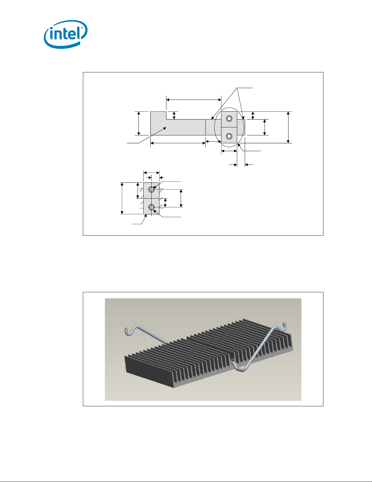
Figure 7-4. Retention Mechanism Component Keepout Zones
0.896
0.120
Reference Thermal Solution 2
0.070
"
Component
Keepout
2x
0.060
0.345
0.07"
Component
Keepout
Detail
A
0.165
0.345
Component
Keepout
Note: NOTE: All dimensions are in inches.
0.173
1.156
0.083
0.100
2x
0.038
Plated Through
0.200
2x
0.056
Trace
Keepout
7.5.1 Heatsink Orientation
Since this solution is based on a unidirectional heatsink, mean airflow direction must be
aligned with the direction of the heatsink fins.
Figure 7-5. Short Torsional Clip Heatsink Assembly
Hole
0.170
(0.165)
See Detail
0.100
0.225
A
(0.345)
38 Intel® 631xESB/632xESB I/O Controller Hub Thermal Mechanical Design Guide
Page 39

Reference Thermal Solution 2
7.5.2 Extruded Heatsink Profiles
The reference thermal solution uses an extruded heatsink for cooling the chipset MCH.
Figure 7-6 shows the heatsink profile. Appendix A, “Thermal Solution Component
Suppliers” lists a supplier for this extruded heatsink. Other heatsinks with similar
dimensions and increased thermal performance may be available. Full mechanical
drawing of this heatsink is provided in Appendix B, “Mechanical Drawings.”
7.5.3 Mechanical Interface Material
There is no mechanical interface material associated with this reference solution.
7.5.4 Thermal Interface Material
Please refer to Section 6.5.4 for details.
7.5.4.1 Effect of Pressure on TIM Performance
Please refer to Section 7.5.4.1 for details.
7.5.4.2 Heatsink Clip
Please refer to Section 7.5.4.2 for details.
Figure 7-6. Torsional Clip Heatsink Extrusion Profile
7.5.5 Clip Retention Anchors
Please refer to Section 6.5.6 for details.
7.6 Reliability Guidelines
Please refer to Section 7.6 for details.
§
Intel® 631xESB/632xESB I/O Controller Hub Thermal Mechanical Design Guide 39
Page 40

Reference Thermal Solution 2
40 Intel® 631xESB/632xESB I/O Controller Hub Thermal Mechanical Design Guide
Page 41

Thermal Solution Component Suppliers
A Thermal Solution Component
Suppliers
A.1 Tall Torsional Clip Heatsink Thermal Solution
Part Intel Part Number
Heatsink Assembly includes:
Unidirectional Fin Heatsink
Thermal Interface Material
Torsional Clip
Undirectional Fin Heatsink
(42.30 x 42.30 x 29.0 mm)
Thermal Interface
(PCM45F)
Heatsink Attach Clip D10234-001 CCI/ACK Harry Lin (USA)
Solder-Down Anchor A13494-005 Foxconn
D12403-001 CCI/ACK* Harry Lin (USA)
D12402-001 CCI/ACK Harry Lin (USA)
C34795-001 Honeywell
Supplier
(Part Number)
PCM45 F*
Foxconn Bob Hall (USA)
(HB96030-DW)*
Contact Information
714-739-5797
hlinack@aol.com
Monica Chih (Taiwan)
866-2-29952666, x131
monica_chih@ccic.com.tw
714-739-5797
hlinack@aol.com
Monica Chih (Taiwan)
866-2-29952666, x131
monica_chih@ccic.com.tw
Scott Miller
509-252-2206
scott.miller4@honeywell.com
714-739-5797
hlinack@aol.com
Monica Chih (Taiwan)
866-2-29952666, x131
monica_chih@ccic.com.tw
503-693-3509, x235
bhall@foxconn.com
Julia Jiang (USA)
408-919-6178
juliaj@foxconn.com
Note: The enabled components may not be currently available from all suppliers. Contact the
supplier directly to verify time of component availability.
Intel® 631xESB/632xESB I/O Controller Hub Thermal Mechanical Design Guide 41
Page 42

Thermal Solution Component Suppliers
A.2 Short Torsional Clip Heatsink Thermal Solution
Part Intel Part Number
Heatsink Assembly includes:
Unidirectional Fin Heatsink
Thermal Interface Material
Torsional Clip
Undirectional Fin Heatsink
(42.50 x 60 x 8.9 mm)
Thermal Interface
(PCM45F)
Heatsink Attach Clip D10234-001 CCI/ACK Harry Lin (USA)
Solder-Down Anchor A13494-005 Foxconn
D12405-001 CCI/ACK Harry Lin (USA)
D12404-001 CCI/ACK Harry Lin (USA)
C34795-001 Honeywell
Supplier
(Part Number)
PCM45F
Foxconn Bob Hall (USA)
(HB96030-DW)
Contact Information
714-739-5797
hlinack@aol.com
Monica Chih (Taiwan)
866-2-29952666, x131
monica_chih@ccic.com.tw
714-739-5797
hlinack@aol.com
Monica Chih (Taiwan)
866-2-29952666, x131
monica_chih@ccic.com.tw
Scott Miller
509-252-2206
scott.miller4@honeywell.com
714-739-5797
hlinack@aol.com
Monica Chih (Taiwan)
866-2-29952666, x131
monica_chih@ccic.com.tw
503-693-3509, x235
bhall@foxconn.com
Julia Jiang (USA)
408-919-6178
juliaj@foxconn.com
Note: The enabled components may not be currently available from all suppliers. Contact the
supplier directly to verify time of component availability.
§§
42 Intel® 631xESB/632xESB I/O Controller Hub Thermal Mechanical Design Guide
Page 43

Mechanical Drawings
B Mechanical Drawings
Table B-1 lists the mechanical drawings included in this appendix.
Table B-1. Mechanical Drawing List
Drawing Name Figure Number
Tall Torsional Clip Heatsink Assembly Drawing Figure B-1
Tall Torsional Clip Heatsink Drawing (Sheet 1 0f 2) Figure B-2
Tall Torsional Clip Heatsink Drawing (Sheet 2 0f 2) Figure B-3
Tall Torsional Heatsink Clip Drawing Figure B-4
Short Torsional Clip Heatsink Assembly Drawing Figure B-5
Short Torsional Clip Heatsink Drawing(Sheet 1 of 2) Figure B-6
Short Torsional Clip Heatsink Drawing(Sheet 2 of 2) Figure B-7
Short Torsional Clip Heatsink Clip Drawing Figure B-8
Intel® 631xESB/632xESB I/O Controller Hub Thermal Mechanical Design Guide 43
Page 44
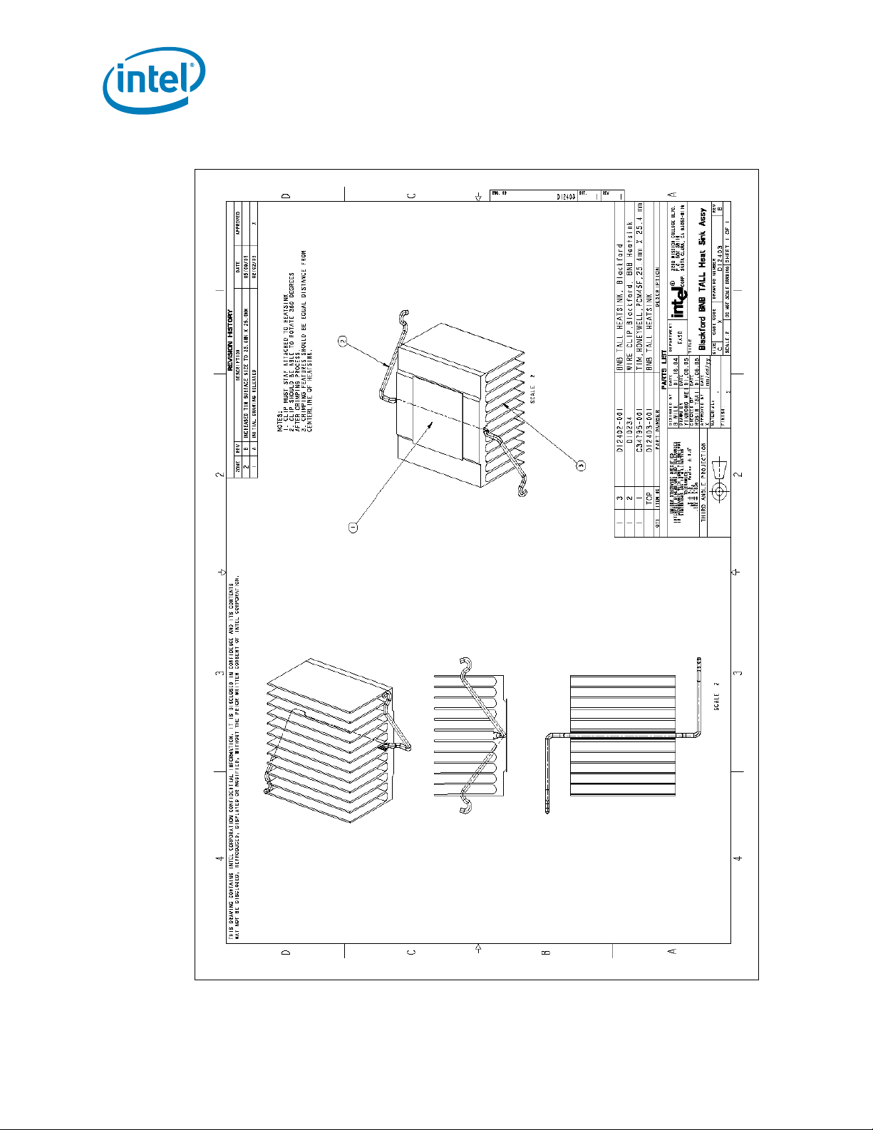
Figure B-1. Tall Torsional Clip Heatsink Assembly Drawing
Mechanical Drawings
44 Intel® 631xESB/632xESB I/O Controller Hub Thermal Mechanical Design Guide
Page 45

Mechanical Drawings
Figure B-2. Tall Torsional Clip Heatsink Drawing (Sheet 1 of 2)
Intel® 631xESB/632xESB I/O Controller Hub Thermal Mechanical Design Guide 45
Page 46

Figure B-3. Tall Torsional Clip Heatsi n k Drawing (Sheet 2 of 2)
Mechanical Drawings
46 Intel® 631xESB/632xESB I/O Controller Hub Thermal Mechanical Design Guide
Page 47

Mechanical Drawings
Figure B-4. Tall Torsional Clip Heatsink Clip Drawing
Intel® 631xESB/632xESB I/O Controller Hub Thermal Mechanical Design Guide 47
Page 48

Figure B-5. Short Torsional Clip Heats ink Assembly Drawing
Mechanical Drawings
48 Intel® 631xESB/632xESB I/O Controller Hub Thermal Mechanical Design Guide
Page 49

Mechanical Drawings
Figure B-6. Short Torsional Clip Heatsink Drawing(Sheet 1 of 2)
Intel® 631xESB/632xESB I/O Controller Hub Thermal Mechanical Design Guide 49
Page 50

Figure B-7. Short Torsional Clip Heatsink Drawing(Sheet 2 of 2)
Mechanical Drawings
50 Intel® 631xESB/632xESB I/O Controller Hub Thermal Mechanical Design Guide
Page 51

Mechanical Drawings
Figure B-8. Short Torsional Clip Heatsink Clip Drawing
Intel® 631xESB/632xESB I/O Controller Hub Thermal Mechanical Design Guide 51
Page 52

Mechanical Drawings
§
52 Intel® 631xESB/632xESB I/O Controller Hub Thermal Mechanical Design Guide
 Loading...