

Page 1

Intel® Server Chassis P4000S Family
Service Guide
A Guide for Technically Qualified Assemblers of Intel® identified
Subassemblies/Products
Order Number: G20364-004
Page 2

Disclaimer
Disclaimer
Information in this document is provided in connection with Intel® products. No license, express or implied, by estoppel or
otherwise, to any intellectual property rights is granted by this document. Except as provided in Intel’s Terms and Conditions
of Sale for such products, Intel assumes no liability whatsoever, and Intel disclaims any express or implied warranty, relating
to sale and/or use of Intel products including liability or warranties relating to fitness for a particular purpose, merchantability,
or infringement of any patent, copyright or other intellectual property right. Intel products are not designed, intended or
authorized for use in any medical, life saving, or life sustaining applications or for any other application in which the failure of
the Intel product could create a situation where personal injury or death may occur. Intel may make changes to
specifications and product descriptions at any time, without notice.
Intel server boards contain a number of high-density VLSI and power delivery components that need adequate airflow for
cooling. Intel’s own chassis are designed and tested to meet the intended thermal requirements of these components when
the fully integrated system is used together. It is the responsibility of the system integrator that chooses not to use Intel
developed server building blocks to consult vendor datasheets and operating parameters to determine the amount of airflow
required for their specific application and environmental conditions. Intel Corporation can not be held responsible if
components fail or the server board does not operate correctly when used outside any of their published operating or nonoperating limits.
Intel, Intel Pentium, and Intel Xeon are trademarks or registered trademarks of Intel Corporation or its subsidiaries in the
United States and other countries.
* Other names and brands may be claimed as the property of others.
Copyright © 2012 Intel Corporation. All Rights Reserved.
ii Intel® Server Chassis P4000S Service Guide
Page 3

Safety Information
Safety Information
Important Safety Instructions
Read all caution and safety statements in this document before performing any of the instructions.
See also Intel® Server Boards and Server Chassis Safety Information on the Intel® Server
Deployment Toolkit 3.0 CD and/or at
http://www.intel.com/support/motherboards/server/sb/cs-010770.htm.
Wichtige Sicherheitshinweise
Lesen Sie zunächst sämtliche Warnund Sicherheitshinweise in diesem Dokument, bevor Sie eine
der Anweisungen ausführen. Beachten Sie hierzu auch die Sicherheitshinweise zu Intel®Serverplatinen und Servergehäusen auf der Intel® Server Deployment Toolkit 3.0 CD oder unter
http://www.intel.com/support/motherboards/server/sb/cs-010770.htm.
Consignes de sécurité
Lisez attention toutes les consignes de sécurité et les mises en garde indiquées dans ce document
avant de suivre toute instruction. Consultez Intel® Server Boards and Server Chassis Safety
Information sur le Intel® Server Deployment Toolkit 3.0 CD ou bien rendez-vous sur le site
http://www.intel.com/support/motherboards/server/sb/cs-010770.htm.
Instrucciones de seguridad importantes
Lea todas las declaraciones de seguridad y precaución de este documento antes de realizar
cualquiera de las instrucciones. Vea Intel® Server Boards and Server Chassis Safety Information en
el Intel® Server Deployment Toolkit 3.0 CD y/o en
http://www.intel.com/support/motherboards/server/sb/cs-010770.htm.
重要安全指导
在执行任何指令之前,请阅读本文档中的所有注意事项及安全声明。和/或
http://www.intel.com/support/motherboards/server/sb/cs-010770.htm 上的 Intel® Server Boards
and Server Chassis Safety Information(《Intel 服务器主板与服务器机箱安全信息》)。
Intel® Server Chassis P4000S Service Guide iii
Page 4

Warnings
Warnings
Heed safety instructions: Before working with your server product, whether
you are using this guide or any other resource as a reference, pay close
attention to the safety instructions. You must adhere to the assembly
instructions in this guide to ensure and maintain compliance with existing
product certifications and approvals. Use only the described, regulated
components specified in this guide. Use of other products/components will
void the UL listing and other regulatory approvals of the product and will
most likely result in noncompliance with product regulations in the region(s)
in which the product is sold.
System power on/off: The power button DOES NOT turn off the system AC
power. To remove power from the system, you must unplug the AC power
cord from the wall outlet. Make sure the AC power cord is unplugged before
you open the chassis, add, or remove any components.
Hazardous conditions, devices and cables: Hazardous electrical conditions
may be present on power, telephone, and communication cables. Turn off the
server and disconnect the power cord, telecommunications systems, networks,
and modems attached to the server before opening it. Otherwise, personal
injury or equipment damage can result.
Electrostatic discharge (ESD) and ESD protection: ESD can damage disk
drives, boards, and other parts. We recommend that you perform all
procedures in this chapter only at an ESD workstation. If one is not available,
provide some ESD protection by wearing an antistatic wrist strap attached to
chassis groundany unpainted metal surfaceon your server when
handling parts.
ESD and handling boards: Always handle boards carefully. They can be
extremely sensitive to ESD. Hold boards only by their edges. After removing
a board from its protective wrapper or from the server, place the board
component side up on a grounded, static free surface. Use a conductive foam
pad if available but not the board wrapper. Do not slide board over any
surface.
Installing or removing jumpers: A jumper is a small plastic encased
conductor that slips over two jumper pins. Some jumpers have a small tab on
top that you can grip with your fingertips or with a pair of fine needle nosed
pliers. If your jumpers do not have such a tab, take care when using needle
nosed pliers to remove or install a jumper; grip the narrow sides of the
jumper with the pliers, never the wide sides. Gripping the wide sides can
damage the contacts inside the jumper, causing intermittent problems with
the function controlled by that jumper. Take care to grip with, but not
squeeze, the pliers or other tool you use to remove a jumper, or you may
bend or break the pins on the board.
iv Intel® Server Chassis P4000S Service Guide
Page 5
Preface
For this information or software
Use this Document or Software
For in-depth technical information
about this product.
Intel® Server Chassis P4000S Family Technical Product Specification
See the section on the web page titled, “Technical Specifications”.
If you just received this product and
need to install it.
Intel® Server Chassis P4000S Family Quick Installation User’s Guide
See the section on the web page titled, “Installation and Use”.
Accessories or other Intel® server
products.
Spares and Configuration Guide
See the section on the web page titled, “Installation and Use”.
To quickly and efficiently select
compatible components to design a
complete system.
Intel® Server Configurator tool
A link to the Intel® Server Configurator tool is available under “Other
Resources” at the right side of the web page screen
Preface
About this Manual
Thank you for purchasing and using the Intel® Server Chassis P4000S family products.
This manual is written for system technicians who are responsible for troubleshooting, upgrading,
and repairing this server chassis. This document provides a brief overview of the features of the
board/chassis, a list of accessories or other components you may need, troubleshooting information,
and instructions on how to add and replace components on the Intel® Server Chassis P4000S family.
For the latest version of this manual, refer to http://www.intel.com/p/en_US/support.
Manual Organization
Chapter 1 provides a brief overview of the Intel® Server Chassis P4000S family. In this chapter, you
will find a list of the server chassis features, photos of the product, and product diagrams to help
you identify components and their locations.
Chapter 2 provides instructions on adding and replacing components. Use this chapter for step-bystep instructions and diagrams for installing or replacing components such as thefan, power supply,
front panel board, and battery, among other components.
Chapter 3 provides technical reference information on cable routing, power supply specifications,
and system environment requirements.
At the back of this document, you will find appendices on safety, getting help, and warranty
information.
Additional Information and Software
If you need more information about this product or information about the accessories that you can
use with this server chassis, use the following resources. These files are available at:
http://www.intel.com/support.
Unless otherwise indicated in the following table, once on this web page, type the document or
software name in the search field at the left side of the screen and select the option to search “This
Product”.
Intel® Server Chassis P4000S Service Guide v
Page 6
Preface
For this information or software
Use this Document or Software
Hardware (peripheral boards, adapter
cards, and so on) and operating
systems tested with this product.
Tested Hardware and Operating System List
See the section on the compatible server/workstation board web page
titled, “Compatibility”.
To make sure your system falls within
the allowed power budget.
Power Budget Analysis Tool
See the section on the web page titled, “Installation and Use”.
For software to manage your Intel®
server.
Intel Server Management Software
See the section on the web page titled, “Installation and Use”.
For firmware and drivers.
Firmware and Drivers
See the section on the web page titled, “Software and Drivers”.
vi Intel® Server Chassis P4000S Service Guide
Page 7

Table of Contents
Table of Contents
Safety Information ...............................................................................................iii
Preface ..................................................................................................................v
1 Server Chassis Features ................................................................................1
Chassis Features .................................................................................................................. 2
Component Identification ....................................................................................................... 3
Front Panel ........................................................................................................................... 9
Back Panel .......................................................................................................................... 10
4x3.5'' Hard Drive Backplane .............................................................................................. 11
2 Hardware Installations and Upgrades .........................................................13
Before You Begin ................................................................................................................ 13
Tools and Supplies Needed ........................................................................................ 13
System Reference ...................................................................................................... 13
Removing and Installing the Chassis Cover ........................................................................ 14
Removing the Chassis Cover ................................ ..................................................... 14
Installing the Chassis Cover ....................................................................................... 15
Removing and Installing the Front Bezel ............................................................................. 15
Removing the Front Bezel .......................................................................................... 15
Installing the Front Bezel ............................................................................................ 16
Removing and Installing a DVD or CD-ROM Drive .............................................................. 17
Removing a DVD or CD-ROM Drive ........................................................................... 17
Installing a DVD or CD-ROM Drive ............................................................................. 17
Removing and Installing the Fixed HDD EMI Shield ............................................................ 18
Removing the Fixed HDD EMI Shield ......................................................................... 18
Installing the EMI Shield ............................................................................................. 19
Removing and Installing Fixed Hard Drive(s) ...................................................................... 20
Removing Fixed Hard Drive(s) .................................................................................... 20
Installing Fixed Hard Drive(s) ...................................................................................... 21
Removing and Installing 4x3.5'' Hot-swap Hard Drive Cage Assembly ................................ 24
Removing 4x3.5'' Hot-swap Hard Drive Cage with Backplane .................................... 24
Installing 4x3.5'' Hot-swap Hard Drive Cage with Backplane ...................................... 25
Removing and Installing 4x3.5'' Hot-swap Backplane .......................................................... 27
Removing 4x3.5'' Hot-swap Backplane ....................................................................... 27
Installing 4x3.5'' Hot-swap Backplane ......................................................................... 28
Installing Hot-swap Hard Drive ............................................................................................ 29
Installing 3.5" Hard Disk Drive .................................................................................... 29
Installing 2.5" Hard Disk Drive .................................................................................... 30
Removing and Installing Airduct .......................................................................................... 32
Installing the Airduct ................................................................................................... 32
Removing the Airduct ................................................................................................ . 33
Removing and Installing the Fixed Power Supply ................................................................ 34
Removing the Fixed Power Supply ................................ ............................................. 34
Installing the Fixed Power Supply ............................................................................... 34
Installing an Additional Hot-swap Power Supply Module ..................................................... 35
Intel® Server Chassis P4000S Service Guide vii
Page 8

Table of Contents
Replacing a Hot Swap Power Supply Module...................................................................... 36
Replacing the Power Distribution Board for 460W PSUs ..................................................... 37
Removing and Installing the Rear Fixed Fan ....................................................................... 42
Removing the Rear Fixed Fan .................................................................................... 42
Installing the Rear Fixed Fan ...................................................................................... 42
Removing and Installing the Front Fixed Fan ...................................................................... 43
Removing the Front Fixed Fan ................................................................................... 43
Installing the Front Fixed Fan ................................................................ ..................... 44
Removing and Installing the PCI Card Guide ...................................................................... 46
Removing PCI Card Guide ......................................................................................... 46
Installing PCI Card Guide ........................................................................................... 46
Removing and Installing PCI Add-in Board(s)...................................................................... 47
Removing PCI Add-in Board(s) ................................................................................... 47
Installing PCI Add-in Board(s) for P4304XXSFCN and P4304XXSHCN ..................... 48
Installing non-Full Length PCI Add-in Board(s) for
P4304XXSFEN/P4304XXSHEN/P4304XXSFDR/P4304XXSHDR/P4304XXS
FDN/P4304XXHDN ...................................................................................... 50
Installing Full Length PCI Add-in Board(s) for
P4304XXSFEN/P4304XXSHEN/P4304XXSFDR/P4304XXSHDR/P4304XXS
FDN/P4304XXHDN ...................................................................................... 52
Removing and Installing the Chassis Feet ........................................................................... 54
Removing the Chassis Feet ........................................................................................ 54
Installing the Chassis Feet .......................................................................................... 55
Removing and Installing the Front Panel Tray ..................................................................... 56
Removing the Front Control Panel Tray ...................................................................... 56
Installing the Fron Panel Tray ..................................................................................... 57
Replacing the Front Panel Board......................................................................................... 59
Installing and/or Removing a Server/Workstation Board ...................................................... 60
Installing Alternate Serial Port ............................................................................................. 61
Connecting and Disconnecting Cables to or from Server Workstation Board ...................... 62
Connecting Cables to Server/Workstation Board ........................................................ 62
Removing Cables from Server/Workstation Board ...................................................... 62
Intel® Remote Management Module 4 ................................................................................. 63
Mechanical Locks ................................................................................................................ 63
3 Technical Reference .....................................................................................65
Power Supply Specification ................................................................................................. 65
365-W Single Power Supply Input Voltage ................................................................. 65
365-W Single Power Supply Output Voltages ............................................................. 65
460-W Hot-swap Power Supply Input Voltage ............................................................ 65
460-W Hot-swap Power Supply Output Voltages ........................................................ 66
550-W Single Power Supply Input Voltage ................................................................. 66
550-W Single Power Supply Output Voltages ............................................................. 66
System Environmental Requirements ................................................................................. 66
Current Usage ..................................................................................................................... 67
Calculation Power Usage ........................................................................................... 67
viii Intel® Server Chassis P4000S Service Guide
Page 9

Table of Contents
Appendix A: Regulatory and Compliance Information ...................................69
Appendix B: Safety Information ........................................................................70
Appendix C: Installation/Assembly Safety Instructions .................................71
Appendix D: Getting Help ..................................................................................72
Warranty Information .................................................................................................. 72
Appendix E: Intel® Server Issue Report Form..................................................73
Appendix F: Warranty ........................................................................................78
Limited Warranty for Intel® Chassis Subassembly Products ................................................ 78
Extent of Limited Warranty .................................................................................................. 78
Warranty Limitations and Exclusions ................................................................................... 79
Limitations of Liability.................................................................................................. 79
How to Obtain Warranty Service ......................................................................................... 79
Telephone Support ..................................................................................................... 79
Returning a Defective Product .................................................................................... 80
Intel® Server Chassis P4000S Service Guide ix
Page 10

List of Figures
List of Figures
Figure 1. Chassis Front View for Fixed Hard Drive Configuration ................................................ 1
Figure 2. Chassis Front View for Hot-swap Hard Drive Configuration ......................................... 1
Figure 3. Internal Chassis View of Intel® Server Chassis P4304XXSFCN ................................... 3
Figure 4. Internal Chassis View of Intel® Server Chassis P4304XXSHCN ................................... 4
Figure 5. Internal Chassis View of Intel® Server Chassis P4304XXSFEN .................................... 5
Figure 6. Internal Chassis View of Intel® Server Chassis P4304XXSHEN ................................... 6
Figure 7. Internal Chassis View of Intel® Server Chassis P4304XXSFDR ................................... 7
Figure 8. Internal Chassis View of Intel® Server Chassis P4304XXSHDR ................................... 8
Figure 9. Front Panel Controls and Indicators ............................................................................. 9
Figure 10. Back Panel Layout (with Fixed Power Supply) ......................................................... 10
Figure 11. Back Panel Layout (with Hot-swap Power Supply) ................................................... 11
Figure 12. 4x3.5'' HSBP Board (Rear View) .............................................................................. 12
Figure 13. 4x3.5'' HSBP Board Layout (Front View) .................................................................. 12
Figure 14. Removing the Chassis Cover ................................................................................... 14
Figure 15. Installing the Chassis Cover ..................................................................................... 15
Figure 16. Removing the Front Bezel ........................................................................................ 16
Figure 17. Installing the Front Bezel .......................................................................................... 16
Figure 18. Removing DVD or CD-ROM Drive ........................................................................... 17
Figure 19. Re-inserting Empty EMI Shield ................................................................................. 17
Figure 20. Removing EMI Shield ............................................................................................... 18
Figure 21. Installing DVD or CD-ROM Drive ............................................................................. 18
Figure 22. Removing the EMI Shield ......................................................................................... 19
Figure 23. Installing the EMI Shield ........................................................................................... 19
Figure 24. Removing Fixed Hard Drives .................................................................................... 20
Figure 25. Removing the 3.5'' HDD from Fixed HDD tray .......................................................... 20
Figure 26. Removing the 2.5'' HDD from Fixed HDD tray .......................................................... 21
Figure 27. Reinstalling the HDD Carrier Tray ............................................................................ 21
Figure 28. Removing Fixed Hard Drive ..................................................................................... 22
Figure 29. Securing the 3.5'' HDD on Fixed HDD Carrier Tray .................................................. 22
Figure 30. Securing the 2.5'' HDD on Fixed HDD Carrier Tray .................................................. 23
Figure 31. Inserting the HDD Carrier Tray ................................................................................. 23
Figure 32. Removing the 4x3.5'' HDD Cage .............................................................................. 24
Figure 33. Removing the EMI shield ................................................................ ......................... 25
Figure 34. Installing the EMI shield ........................................................................................... 26
Figure 35. Installing the 4x3.5'' Hot-Swap Hard Drive Cage ...................................................... 26
Figure 36. 4x3.5'' Hot Swap Backplane Cable Connections ...................................................... 27
Figure 37. Removing 4x3.5'' Hot-swap Backplane .................................................................... 28
Figure 38. Installing 4x3.5” Hot-swap Backplane ....................................................................... 28
Figure 39. Removing the 2.5" HDD interface bracket from Carrier ............................................ 29
Figure 40. Installing the 3.5" HDD into the Carrier ..................................................................... 30
Figure 41. Removing the 2.5" HDD interface bracket from Carrier ............................................ 30
Figure 42. Breaking off the tab on the bracket ........................................................................... 31
Figure 43. Installing 2.5" HDD interface bracket into Carrier ..................................................... 31
Figure 44. Installing the 2.5" HDD into carrier ........................................................................... 32
Figure 45. Installing the Airduct ................................................................................................. 33
Figure 46. Removing the Airduct ............................................................................................... 33
Figure 47. Removing Fixed Power Supply ................................................................................ 34
x Intel® Server Chassis P4000S Service Guide
Page 11

List of Figures
Figure 48. Installing Fixed Power Supply .................................................................................. 35
Figure 49. Removing Power Supply Filler Panel ....................................................................... 36
Figure 50. Installing Additional Hot-swap Power Supply Module ............................................... 36
Figure 51. Removing Hot-swap Power Supply Module from Chassis ........................................ 36
Figure 52. Installing Hot-swap Power Supply Module into Chassis ........................................... 37
Figure 53. Removing Hot-swap Power Supply Module from Chassis ........................................ 37
Figure 54. Loosening the Bracket with Power Distribution Board from Chassis ......................... 38
Figure 55. Removing the Bracket with Power Distribution Board from Chassis ......................... 38
Figure 56. Removing the Power Distribution Board from Bracket .............................................. 39
Figure 57. Sliding the New Power Distribution Board in Bracket ............................................... 39
Figure 58. Securing the New Power Distribution Board in Bracket ............................................ 40
Figure 59. Sliding the Bracket into Power Supply Cage ............................................................ 40
Figure 60. Securing the Bracket into Power Supply Cage ................................ ......................... 41
Figure 61. Installing Hot-swap Power Supply Module into Chassis ........................................... 41
Figure 62. Removing the Rear Fixed Fan .................................................................................. 42
Figure 63. Installing the Rear Fixed Fan.................................................................................... 43
Figure 64. Removing the Front Fixed Fan ................................................................ ................. 44
Figure 65. Installing the Front Fixed Fan ................................................................................... 45
Figure 66. Removing the PCI Guard ......................................................................................... 46
Figure 67. Installing the PCI Guard ................................................................ ........................... 47
Figure 68. Removing the PCI add-in card ................................................................................. 48
Figure 69. Preparing Chassis for Addition of PCI add-in board ................................................. 49
Figure 70. Open the back panel PCI add-in board retentaion device ......................................... 49
Figure 71. Installing PCI Add-in Board ...................................................................................... 50
Figure 72. Preparing Chassis for Addition of PCI add-in board ................................................. 51
Figure 73. Open the back panel PCI add-in board retentaion device ......................................... 51
Figure 74. Installing PCI Add-in Board ...................................................................................... 52
Figure 75. Front fixed system fans ............................................................................................ 53
Figure 76. Assemblying the fan in fan kit ................................................................................... 53
Figure 77. Insert the fan assembly from front of the chassis...................................................... 54
Figure 78. Installing the PCI Guard ................................................................ ........................... 54
Figure 79. Removing the Chassis Feet ..................................................................................... 55
Figure 80. Installing the Chassis Feet ....................................................................................... 55
Figure 81. Disconnecting the Cables from the Server Board ..................................................... 56
Figure 82. Sliding the Front Panel Tray out from the Chassis .................................................... 57
Figure 83. Disconnecting the Cables from Front Panel Board ................................................... 57
Figure 84. Connecting the Cables to the Front Panel Board...................................................... 58
Figure 85. Installing the Front Panel Tray in Chassis ................................................................ 58
Figure 86. Connecting the Cables to Server Board the Front Panel Tray in Chassis ................. 59
Figure 87. Removing the Front Panel Board ............................................................................. 60
Figure 88. Removing and Installing the Cap on Front Panel Board ........................................... 60
Figure 89. Installing the New Front Panel Board ....................................................................... 60
Figure 90. Installing the Alternate Serial Port Knockout ............................................................. 62
Figure 91. RMM4 knockout ................................................................................................ ....... 63
Figure 92. Mechanical Locks ..................................................................................................... 64
Intel® Server Chassis P4000S Service Guide xi
Page 12

List of Tables
List of Tables
Table 1. Breakdown of Intel® Server Chassis P4000S family ....................................................... 2
Table 2. Intel® Server Chassis P4000S Family Base Features .................................................... 2
Table 3. Front Panel LED Functionality ....................................................................................... 9
Table 4. Power Supply Output Voltages .................................................................................... 65
Table 5. Power Supply Output Voltages .................................................................................... 66
Table 6. Power Supply Output Voltages .................................................................................... 66
Table 7. Environmental Requirements ...................................................................................... 66
Table 8. Power Usage Worksheet ............................................................................................. 67
Table 9. Power Usage Worksheet 2 .......................................................................................... 68
xii Intel® Server Chassis P4000S Service Guide
Page 13
Server Chassis Features
1 Server Chassis Features
This chapter briefly describes the main features of the Intel® Server Chassis P4000S family.
This chapter provides a list of the server chassis features, and diagrams showing the location of
important components and connections on the server chassis.
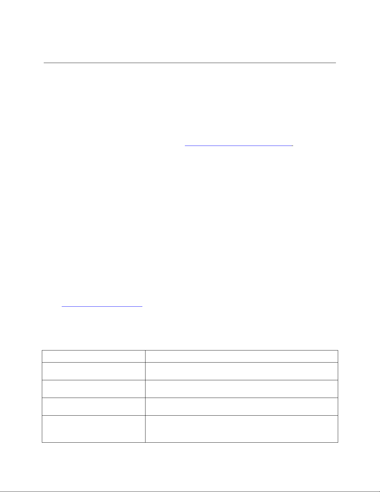
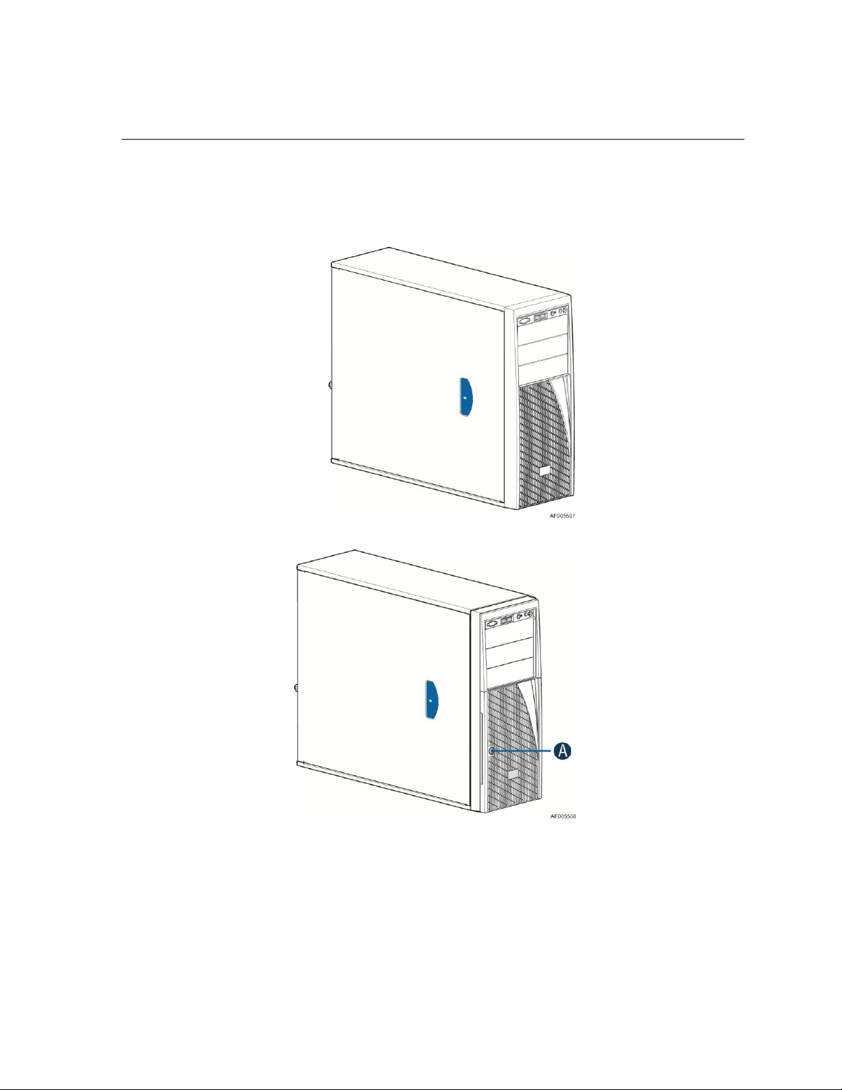
Figure 1. Chassis Front View for Fixed Hard Drive Configuration
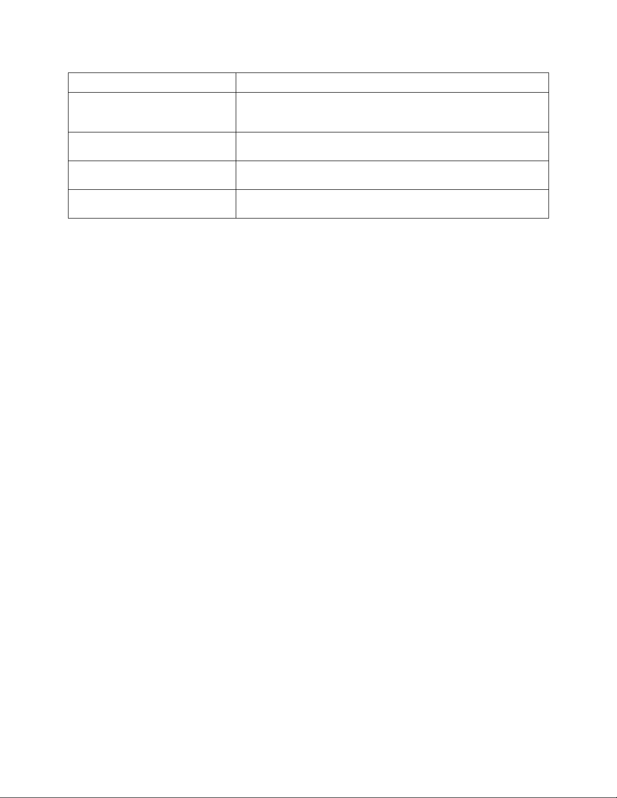
A. Front Door Lock
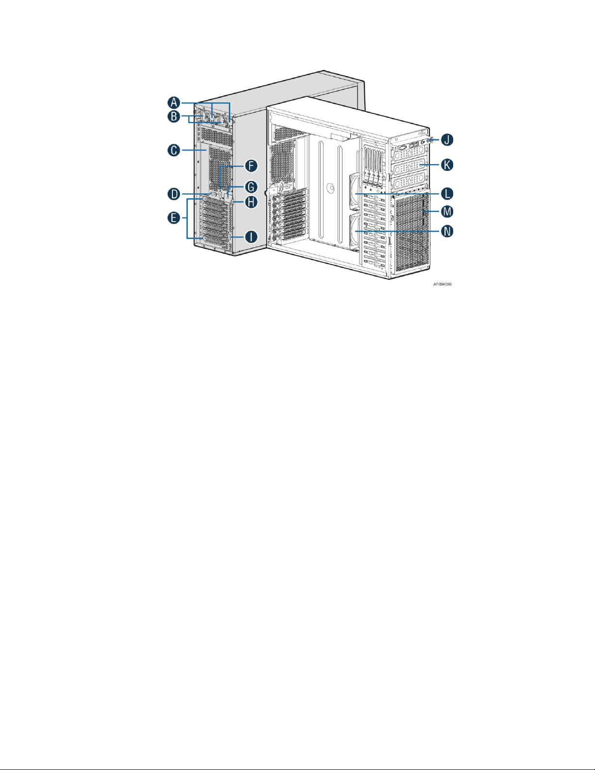
Figure 2. Chassis Front View for Hot-swap Hard Drive Configuration
Intel® Server Chassis P4000S Service Guide 1
Page 14
Server Chassis Features
Intel® Server Chassis
Configuration Intel® Server Board
Intel® Server Chassis P4304XXSFCN
Intel® Server Board S1200BTL, S1200BTS
Intel® Server Chassis P4304XXSHCN
Intel® Server Board S1200BTL
Intel® Server Chassis P4304XXSFEN
Intel® Server Chassis P4304XXSHEN
Intel® Server Chassis P4304XXSFDR
Intel® Server Chassis P4304XXSHDR
Intel® Server Chassis P4304XXSFDN
Intel® Server Chassis P4304XXSHDN
Intel® Server Board S2400SC
Feature
Description
Dimensions
17.2 inches high
6.8 inches wide
22 inches deep (without bezel: 21.5 inches)
Hard Drives
Supports up to 4 fixed/hot-swap HDDs
Peripherals
Three multi-mount 5.25 peripheral bays
Control Panel (dependent
on option selected)
Front Control Panel
Intel® Local Control Panel (Optional)
LEDs and displays
(dependent on option
selected)
With Front Control Panel
o NIC1 Activity
o NIC2 Activity
o NIC3 Activity
o NIC4 Activity
o Power/Sleep
o System Status
o System Chassis Identification
o Hard Drive Activity
Power Supply Options
One fixed 365-W
One fixed 550-W
One hot-swap 460W with low current PDB
Two hot-swap 460-W common redundant power supply with low current PDB
System Fans Option
One 92x38mm fixed system rear fan
Two 92x32mm fixed system fans
USB 2.0
Two front panel USB ports with Front Control Panel
Four Back panel USB ports (depending on server/workstation board)
Video
One rear panel video port
Table 1. Breakdown of Intel® Server Chassis P4000S family
Chassis Features
Table 2. Intel® Server Chassis P4000S Family Base Features
2 Intel® Server Chassis P4000S Service Guide
Page 15
Component Identification
Server Chassis Features
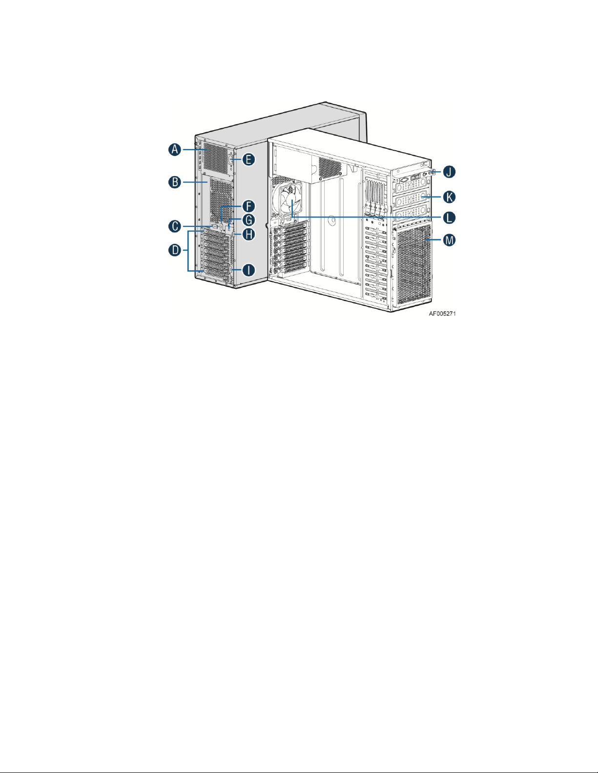
A. 365W Fixed Power supply
B. I/O Ports
C. Alternate RMM4 Knockout
D. PCI Add-in Board Slot Covers
E. AC Input Power Connector
F. Serial Port Knockout
G. A Kensington* Cable Lock Mounting Hole
H. Padlock Loop
I. Alternate RMM4 Knockout
J. Front Control Panel
K. Alternate 5.25” Peripheral Bays
L. 92x38mm System Rear Fan
M. Fixed Hard Drive Bays
Figure 3. Internal Chassis View of Intel® Server Chassis P4304XXSFCN
Intel® Server Chassis P4000S Service Guide 3
Page 16
Server Chassis Features
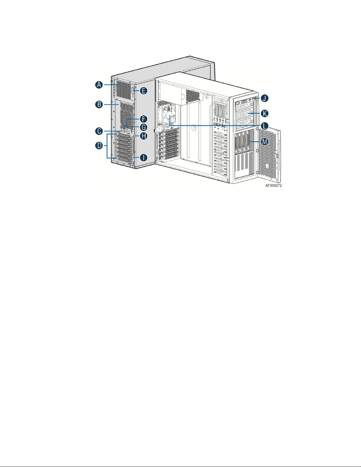
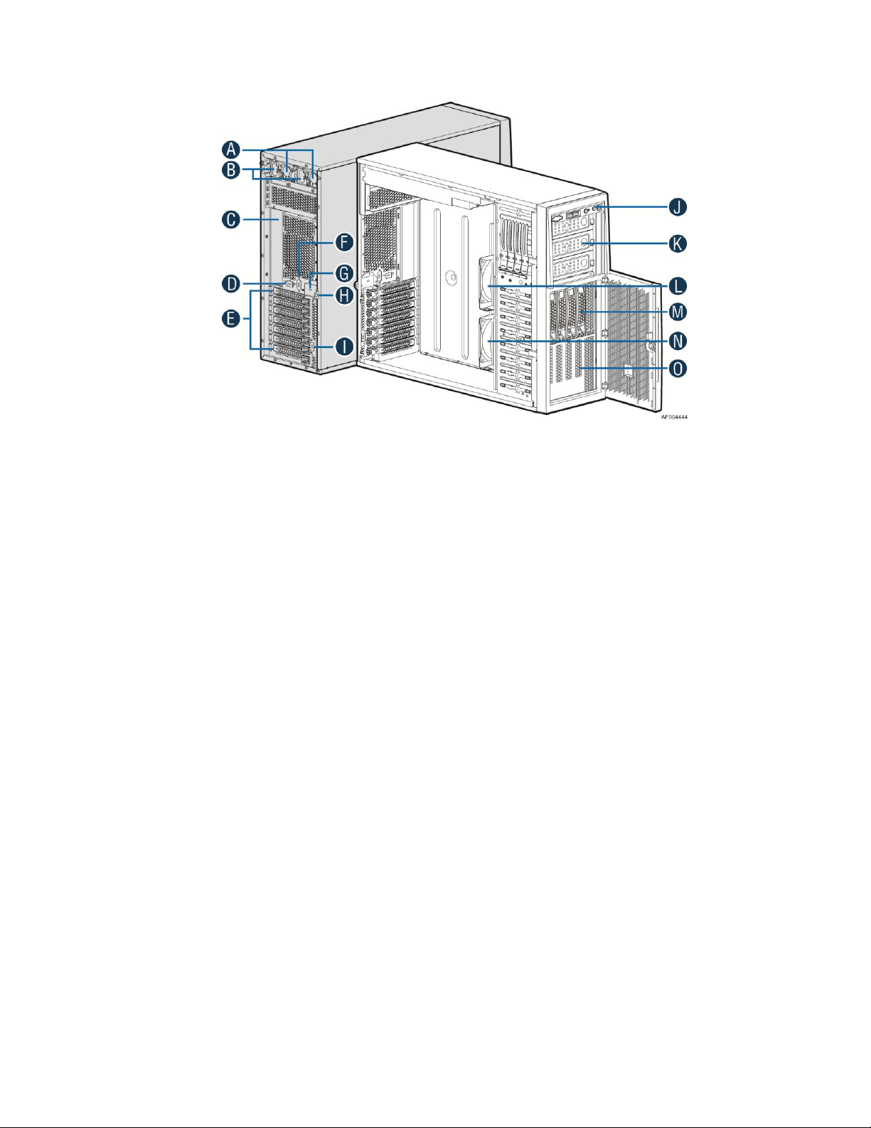
A. 365W Fixed Power Supply
B. I/O Ports
C. Alternate RMM4 Knockout
D. PCI Add-in Board Slot Covers
E. AC Input Power Connector
F. Serial Port Knockout
G. A Kensington* Cable Lock Mounting Hole
H. Padlock Loop
I. Alternate RMM4 Knockout
J. Front Control Panel
K. 5.25” Peripheral Bays
L. 92x38mm System Rear Fan
M. 4x3.5” Hot-swap HDD Cage
Figure 4. Internal Chassis View of Intel® Server Chassis P4304XXSHCN
4 Intel® Server Chassis P4000S Service Guide
Page 17
Server Chassis Features
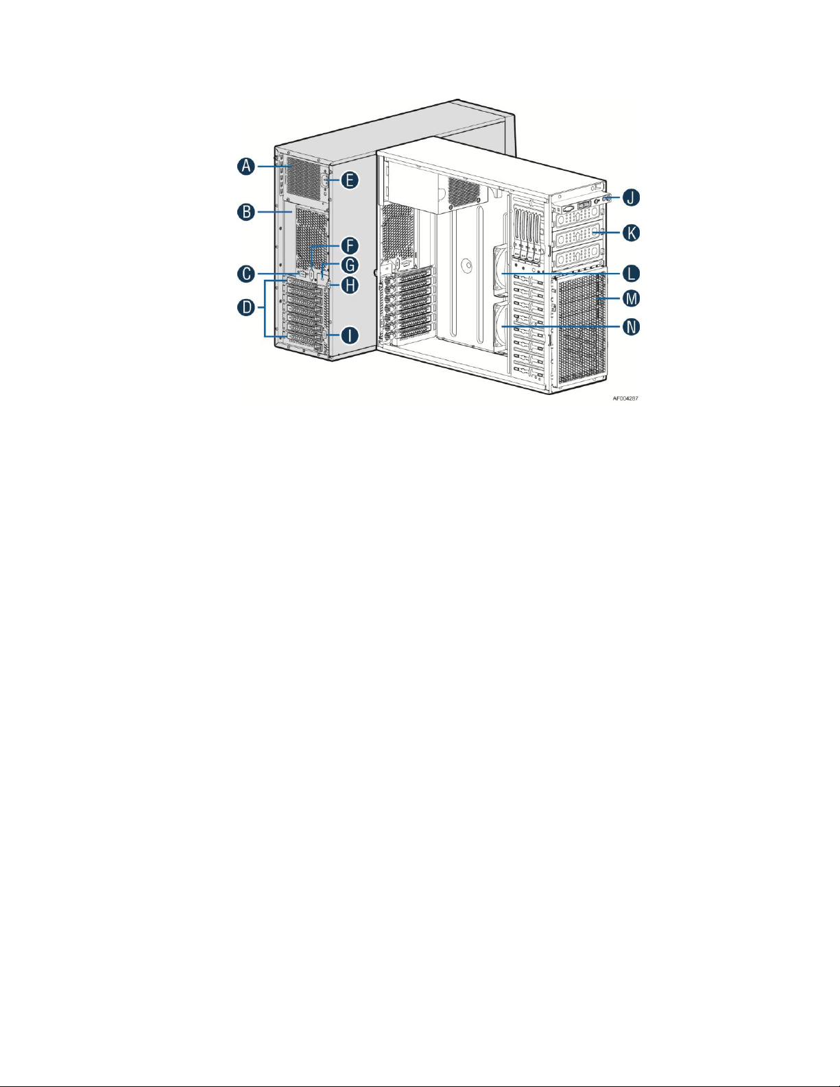
A. 550W Fixed Power supply
B. I/O Ports
C. Alternate RMM4 Knockout
D. PCI Add-in Board Slot Covers
E. AC Input Power Connector
F. Serial Port Knockout
G. A Kensington* Cable Lock Mounting Hole
H. Padlock Loop
I. Alternate RMM4 Knockout
J. Front Control Panel
K. Alternate 5.25” Peripheral Bays
L. CPU Zone System Fan
M. Fixed Hard Drive Bays
N. PCI Zone System Fan
Figure 5. Internal Chassis View of Intel® Server Chassis P4304XXSFEN
Intel® Server Chassis P4000S Service Guide 5
Page 18
Server Chassis Features
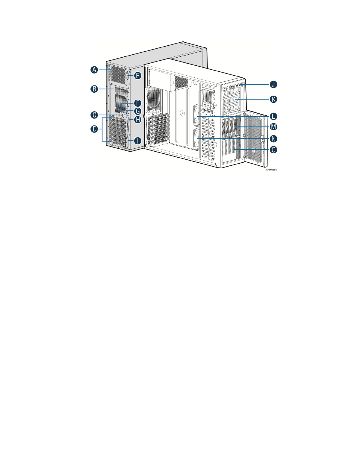
A. 550W Fixed Power supply
B. I/O Ports
C. Alternate RMM4 Knockout
D. PCI Add-in Board Slot Covers
E. AC Input Power Connector
F. Serial Port Knockout
G. A Kensington* Cable Lock Mounting Hole
H. Padlock Loop
I. Alternate RMM4 Knockout
J. Front Control Panel
K. Alternate 5.25” Peripheral Bays
L. CPU Zone System Fan
M. 4x3.5” Hot-swap HDD Cage
N. PCI Zone System Fan
O. Hot-swap HDD EMI Shield
Figure 6. Internal Chassis View of Intel® Server Chassis P4304XXSHEN
6 Intel® Server Chassis P4000S Service Guide
Page 19
Server Chassis Features
A. 460W Redundant Power Supply (Two)
B. AC Input Power Connector (Two)
C. I/O Ports
D. Alternate RMM4 Knockout
E. PCI Add-in Board Slot Covers
F. Serial Port Knockout
G. A Kensington* Cable Lock Mounting Hole
H. Padlock Loop
I. Alternate RMM4 Knockout
J. Front Control Panel
K. Alternate 5.25” Peripheral Bays
L. CPU Zone System Fan
M. Fixed Hard Drive Bays
N. PCI Zone System Fan
Figure 7. Internal Chassis View of Intel® Server Chassis P4304XXSFDR
Intel® Server Chassis P4000S Service Guide 7
Page 20
Server Chassis Features
A. 460W Redundant Power Supply (Two)
B. AC Input Power Connector (Two)
C. I/O Ports
D. Alternate RMM4 Knockout
E. PCI Add-in Board Slot Covers
F. Serial Port Knockout
G. A Kensington* Cable Lock Mounting Hole
H. Padlock Loop
I. Alternate RMM4 Knockout
J. Front Control Panel
K. Alternate 5.25” Peripheral Bays
L. CPU Zone System Fan
M. 4x3.5” Hot-swap HDD Cage
N. PCI Zone System Fan
O. Hot-swap HDD EMI Shield
Figure 8. Internal Chassis View of Intel® Server Chassis P4304XXSHDR
8 Intel® Server Chassis P4000S Service Guide
Page 21
Front Panel
LED
Color
Condition
What It Means
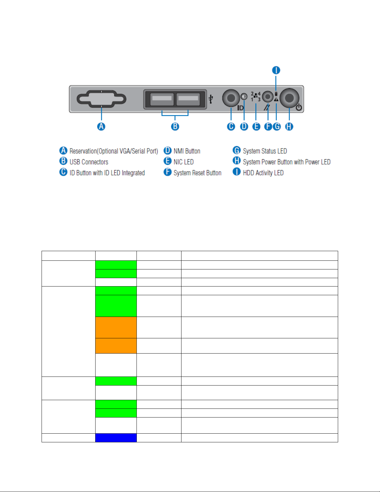
Power/Sleep
Green
On
Power on or S0 sleep.
Green
Blink
S1 sleep or S3 standby only for workstation baseboards.
Off
Off (also sleep S4/S5 modes).
Status
Green
On
System ready/No alarm.
Green
Blink
System ready, but degraded: redundancy lost such as PS or
fan failure; non-critical temp/voltage threshold; battery
failure; or predictive PS failure.
Amber
On
Critical alarm: Voltage, thermal, or power fault; CPU
missing; insufficient power unit redundancy resource offset
asserted.
Amber
Blink
Non-Critical failure: Critical temp/voltage threshold; VDR hot
asserted; min number fans not present or failed.
Off
AC power off: System unplugged.
AC power on: System powered off and in standby, no prior
degraded\non-critical\critical state.
Global HDD
Activity
Green
Blink
HDD access.
Off
No access and no fault.
LAN 1-4
Activity/Link
(LAN 1-2 for
Intel® Server
Board S1200BT)
Green
On
LAN link/no access.
Green
Blink
LAN access.
Off
Idle
Chassis
Blue
On
Front panel chassis ID button pressed.
Server Chassis Features
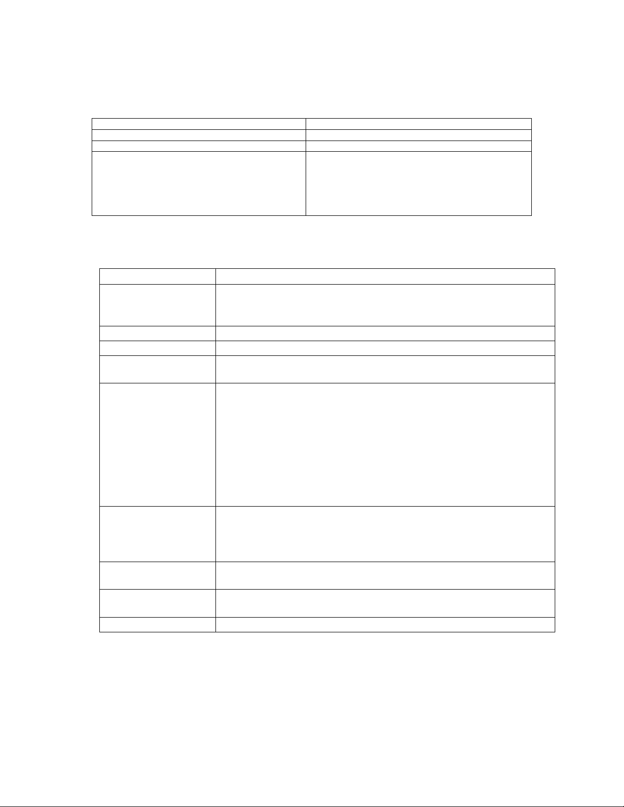
Figure 9. Front Panel Controls and Indicators
Descriptions of the front control panel LEDs are listed in the following table. See your
server/workstation documentation for functionality of the buttons.
Table 3. Front Panel LED Functionality
Intel® Server Chassis P4000S Service Guide 9
Page 22
Server Chassis Features
LED
Color
Condition
What It Means
Identification
Blue
Blink
Unit selected for identification via software.
Off
No identification.
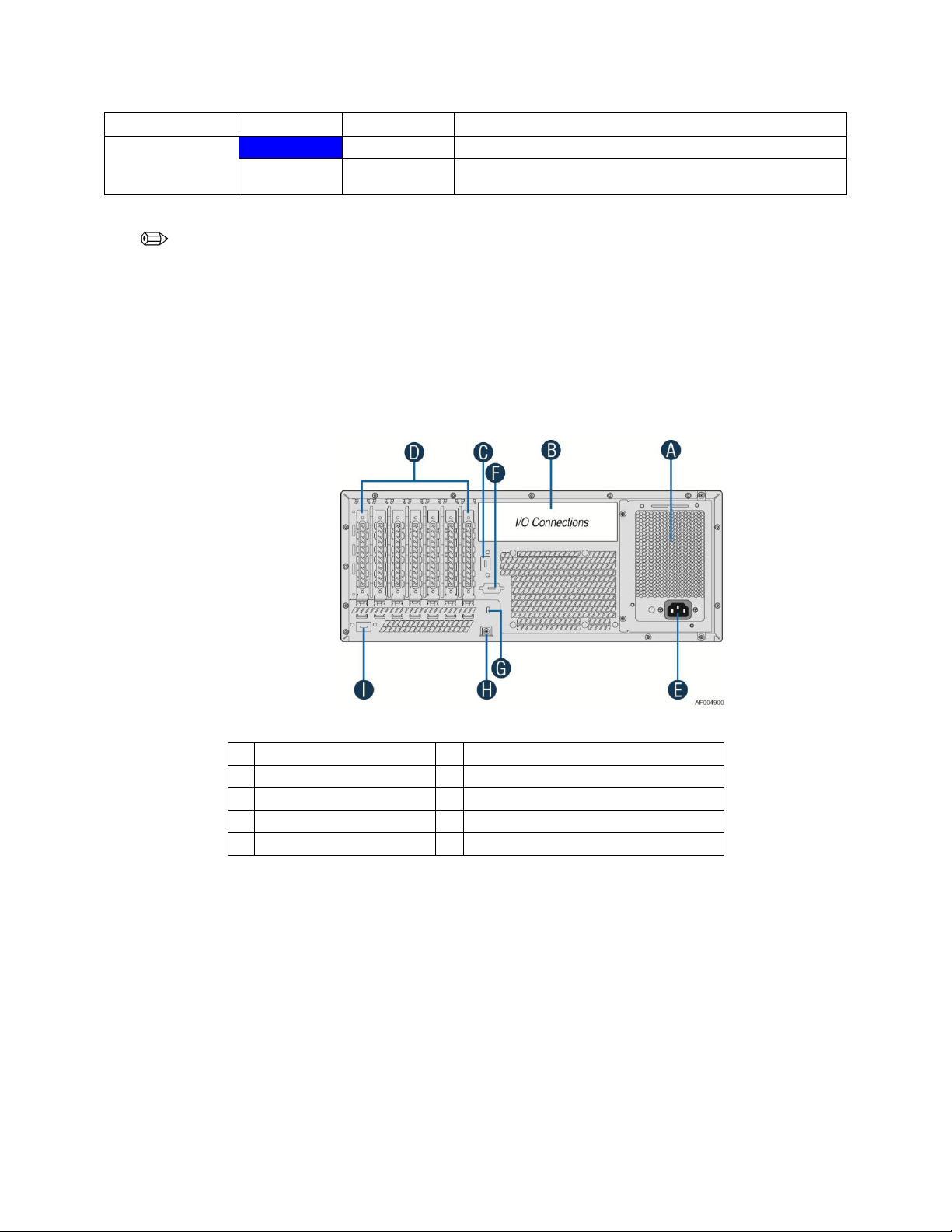
A
Fixed Power Supply
F
Serial-B Port (Optional)
B
IO Connectors
G
Kensington* Cable Lock Mounting Hole
C
RMM4 NIC Port (Optional)
H
Padlock Loop
D
Add in PCI-e cards
I
RMM4 NIC Port (Optional)
E
Power Connector
NOTE
This is dependent on server board support. Not all server boards support all features. For additional
details about control panel functions supported for a specific board, refer to the individual server
board specifications.
Back Panel
The following figure shows the layout of back panel with fixed power supply and hot-swap
redundant power supplies:
Figure 10. Back Panel Layout (with Fixed Power Supply)
10 Intel® Server Chassis P4000S Service Guide
Page 23
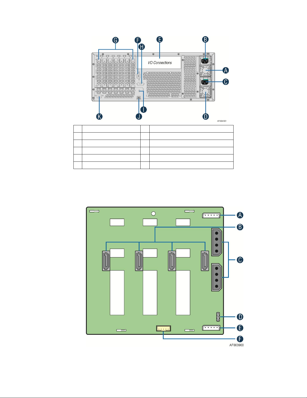
Server Chassis Features
A
Hot-swap Power Supply
G
Add in PCI-e cards
B
Power Connector
H
Serial-B Port (Optional)
C
Power Connector
I
Kensington* Cable Lock Mounting Hole
D
Hot-swap Power Supply
J
Padlock Loop
E
IO Connectors
K
RMM4 NIC Port (Optional)
F
RMM4 NIC Port/(Optional)
Figure 11. Back Panel Layout (with Hot-swap Power Supply)
4x3.5'' Hard Drive Backplane
Intel® Server Chassis P4000S Service Guide 11
A. I2C_In Connectors
Page 24
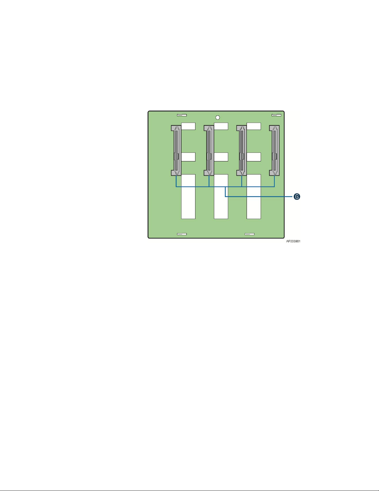
Server Chassis Features
B. SATA/SAS Cable Connctors
C. Power Connectors
D. SATA 6X Mode
E. I2C_Out Connectors
F. SGPIO connector
Figure 12. 4x3.5'' HSBP Board (Rear View)
G. SATA/SAS Hot-swap Drive Connectors
Figure 13. 4x3.5'' HSBP Board Layout (Front View)
12 Intel® Server Chassis P4000S Service Guide
Page 25

Hardware Installations and Upgrades
2 Hardware Installations and
Upgrades
Before You Begin
Before working with your server product, pay close attention to the Appendix B: Safety
Information.
This document provides instructions for adding and replacing chassis components. For
instructions on replacing components on the server board, such as the processor and memory
DIMMs, see the instructions provided with the server/workstation board.
Tools and Supplies Needed
Phillips* (cross head) screwdriver (#1 bit and #2 bit)
Needle nosed pliers
Anti-static wrist strap and conductive foam pad (recommended)
System Reference
All references to left, right, front, top, and bottom assume the reader is facing the front of the
chassis as it would be positioned for normal operation.
Intel® Server Chassis P4000S Service Guide 13
Page 26
Hardware Installations and Upgrades
Removing and Installing the Chassis Cover
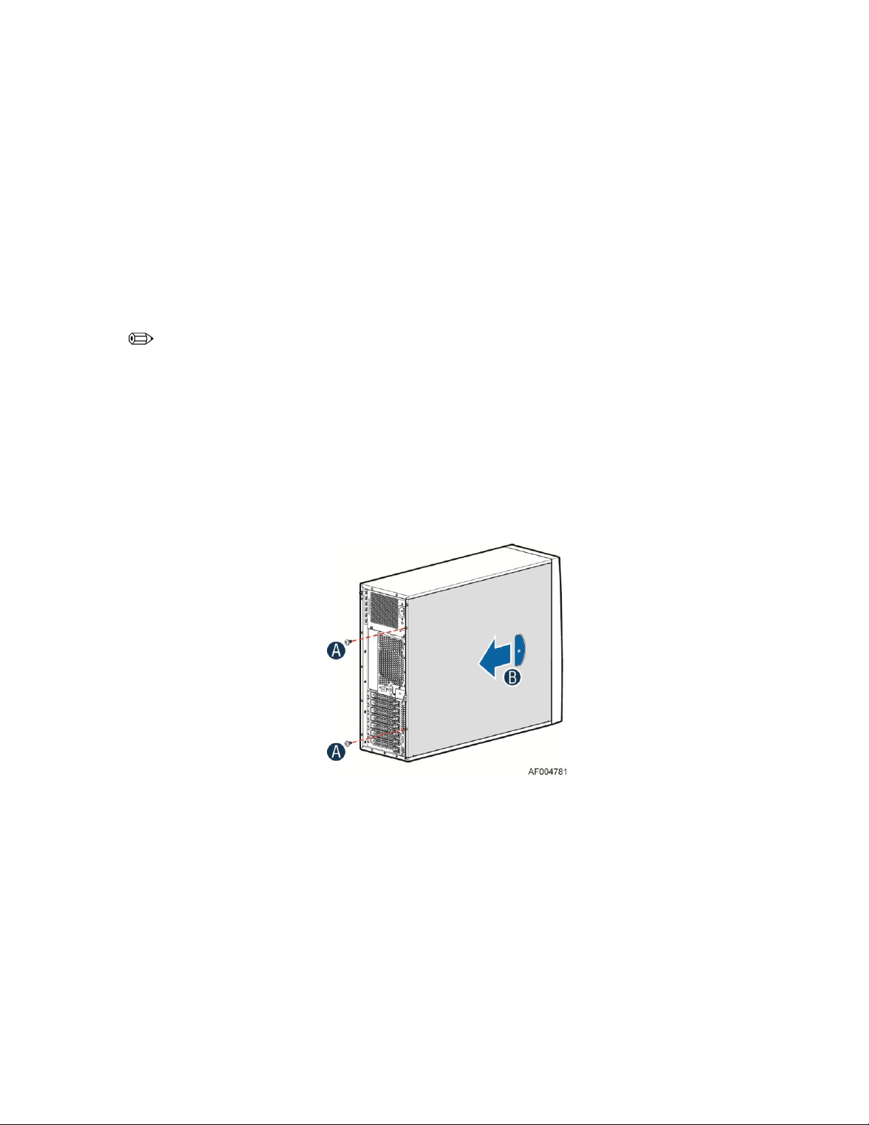
Removing the Chassis Cover
The Intel® Server Chassis P4000S family must be operated with the top cover in place to ensure
proper cooling. You will need to remove the top cover to add or replace components inside of
the platform. Before removing the top cover, power down the server and unplug all peripheral
devices and the AC power cable.
NOTE
A non-skid surface or a stop behind the chassis may be needed to prevent the chassis from slding on your
work surface.
1. Observe the safety and ESD precautions at the beginning of this book.
2. Turn off all peripheral devices connected to the server. Turn off the server.
3. Disconnect the AC power cord.
4. Remove the screws (see letter A).
5. Slide the side cover back (see letter B) and lift the cover outward to remove it.
Figure 14. Removing the Chassis Cover
14 Intel® Server Chassis P4000S Service Guide
Page 27
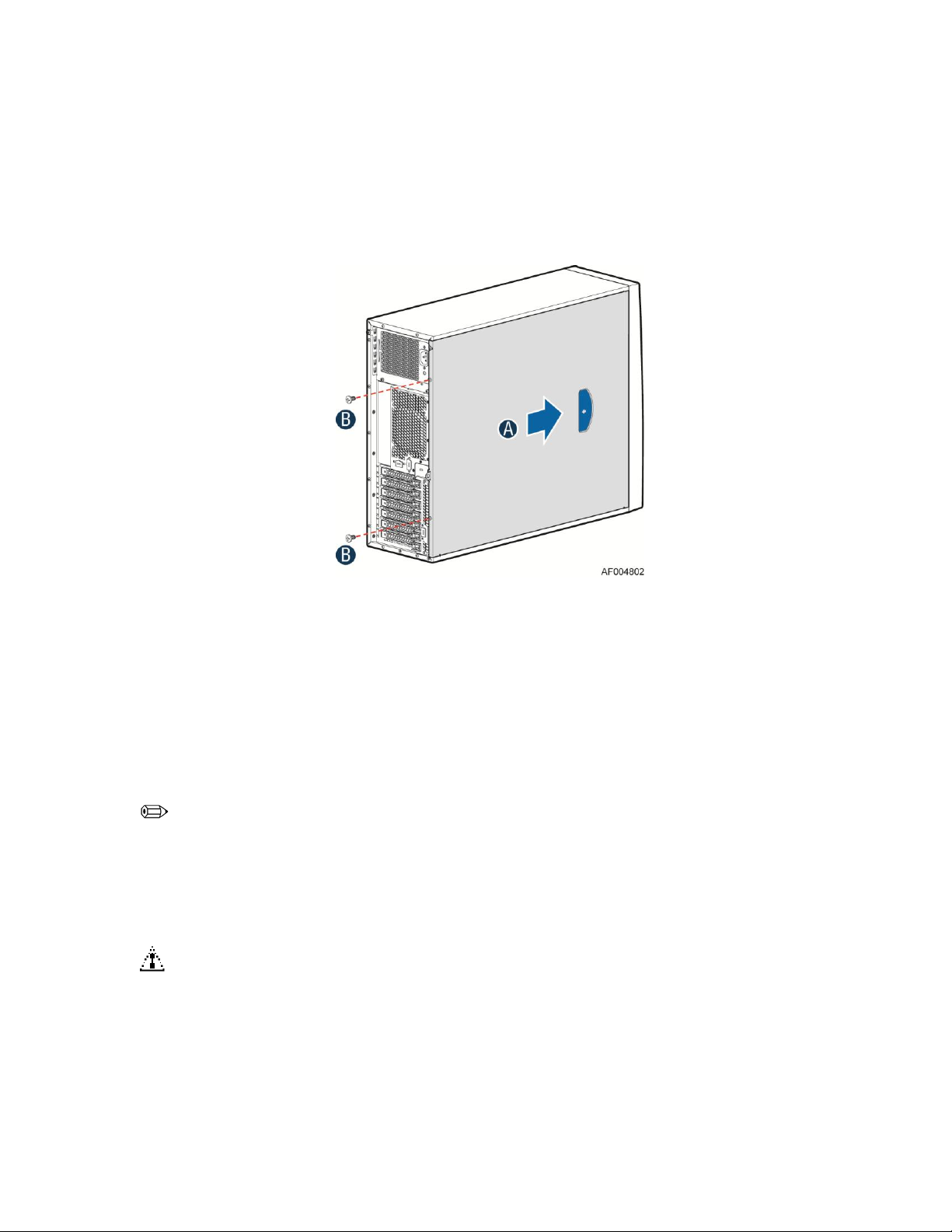
Installing the Chassis Cover
1. Slide the chassis cover on the chassis (see letter A).
2. Latch the cover securely to the chassis.
3. Secure the chassis cover with the screws (see letter B).
Hardware Installations and Upgrades
Figure 15. Installing the Chassis Cover
Removing and Installing the Front Bezel
Removing the Front Bezel
NOTE
With the chassis on its side, position the chassis hanging over the edge of a table or workbench before
removing the bezel.
There are two types of bezel assembly. One is for fixed HDD configuration, and the other type is for Hot-
swap HDD configuration.
CAUTION
Do not rotate the bezel assembly more than 40 degrees or you will damage the bezel assembly.
1. Observe the safety and ESD precautions at the beginning of this book.
2. Power down the server and unplug all peripheral devices and the AC power cable.
3. Remove the chassis cover. For instructions, see “Removing the Chassis Cover”.
Intel® Server Chassis P4000S Service Guide 15
Page 28
Hardware Installations and Upgrades
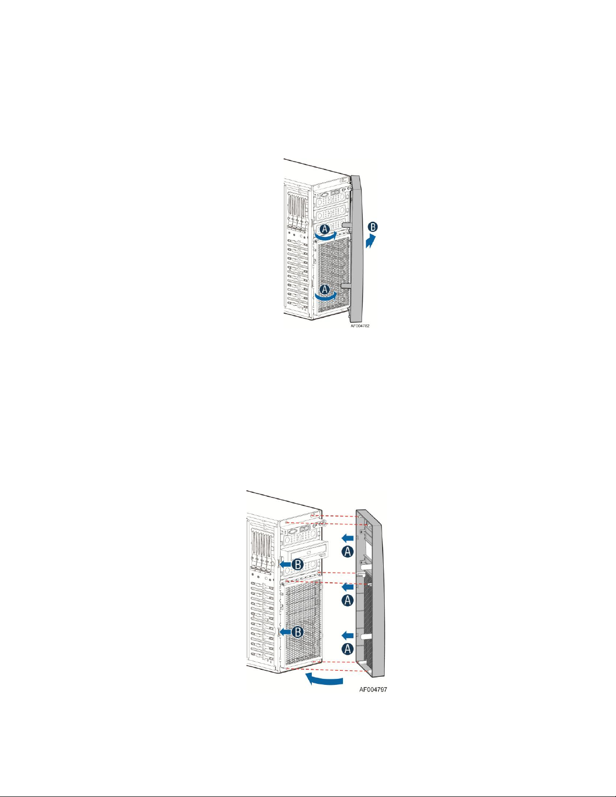
4. Release the two plastic tabs on the left side of the bezel assembly to disengage the tabs, and rotate
the bezel assembly (see letter A) no more than 40 degrees outward.
5. At a 40-degree angle, push the bezel assembly away from the chassis (see letter B).
6. If the bezel assembly does not immediately disconnect from the chassis, tap the left-hand side of the
bezel assembly to disengage the bezel hooks on the right-hand side of the chassis.
Figure 16. Removing the Front Bezel
Installing the Front Bezel
1. Fit the right edge of the bezel assembly against the right side of the chassis.
2. Engage the plastic bezel hooks (see letter A) into the raised metal slots at the chassis edge.
3. Rotate the bezel assembly toward the chassis.
4. Latch the two plastic tabs (see letter B) on the left side of the bezel assembly to the chassis.
Figure 17. Installing the Front Bezel
16 Intel® Server Chassis P4000S Service Guide
Page 29

Hardware Installations and Upgrades
Removing and Installing a DVD or CD-ROM Drive
Removing a DVD or CD-ROM Drive
1. Observe the safety and ESD precautions at the beginning of this book.
2. Power down the server and unplug all peripheral devices and the AC power cable.
3. Remove the chassis cover. For instructions, see “Removing the Chassis Cover”.
4. Remove the front bezel if it is installed. For instructions, see “Removing the Front Bezel”.
5. Disconnect the power and data cables to the DVD/CD-ROM drive.
6. Press on the slide release latches (see letter A in the following figure) and pull the DVD/CD-ROM
drive/slide assembly from the chassis (see letter B in the following figure). Remove the slides from
the DVD or CD-ROM drive (see letter C).
Figure 18. Removing DVD or CD-ROM Drive
7. If not replacing with another drive, reinsert an EMI shield into chassis (see below picture).
Figure 19. Re-inserting Empty EMI Shield
Installing a DVD or CD-ROM Drive
1. Observe the safety and ESD precautions at the beginning of this book.
2. Power down the server and unplug all peripheral devices and the AC power cable.
3. Remove the chassis cover. For instructions, see “Removing the Chassis Cover”.
Intel® Server Chassis P4000S Service Guide 17
Page 30

Hardware Installations and Upgrades
4. Remove the front bezel if it is installed. For instructions, see “Removing the Front Bezel”.
5. Remove an EMI shield (see picture below).
6. Get the slides from the chassis side (see letter B). Attach slides to the DVD or CD-ROM drive by
pressing the slides firmly into the side dimples on the DVD or CD-ROM drives (see letter C). Insert
the drive/slide assembly into the device bay until the slides lock into place (see letter D).
Figure 20. Removing EMI Shield
Figure 21. Installing DVD or CD-ROM Drive
7. Connect the DVD or CD-ROM power cable. See your server board documents for data cable
connection.
Removing and Installing the Fixed HDD EMI Shield
NOTE
For a chassis on its side, position the chassis hanging over the edge of a table or workbench before
removing the bezel.
This procedure applies only to the Intel® Server chassis P4000S family with fixed HDD configuration.
Removing the Fixed HDD EMI Shield
1. Observe the safety and ESD precautions at the beginning of this book.
2. Power down the server and unplug all peripheral devices and the AC power cable.
18 Intel® Server Chassis P4000S Service Guide
Page 31
Hardware Installations and Upgrades
3. Remove the chassis cover. For instructions, see “Removing the Chassis Cover”.
4. Remove the front bezel. For instructions, see “Removing the front bezel”.
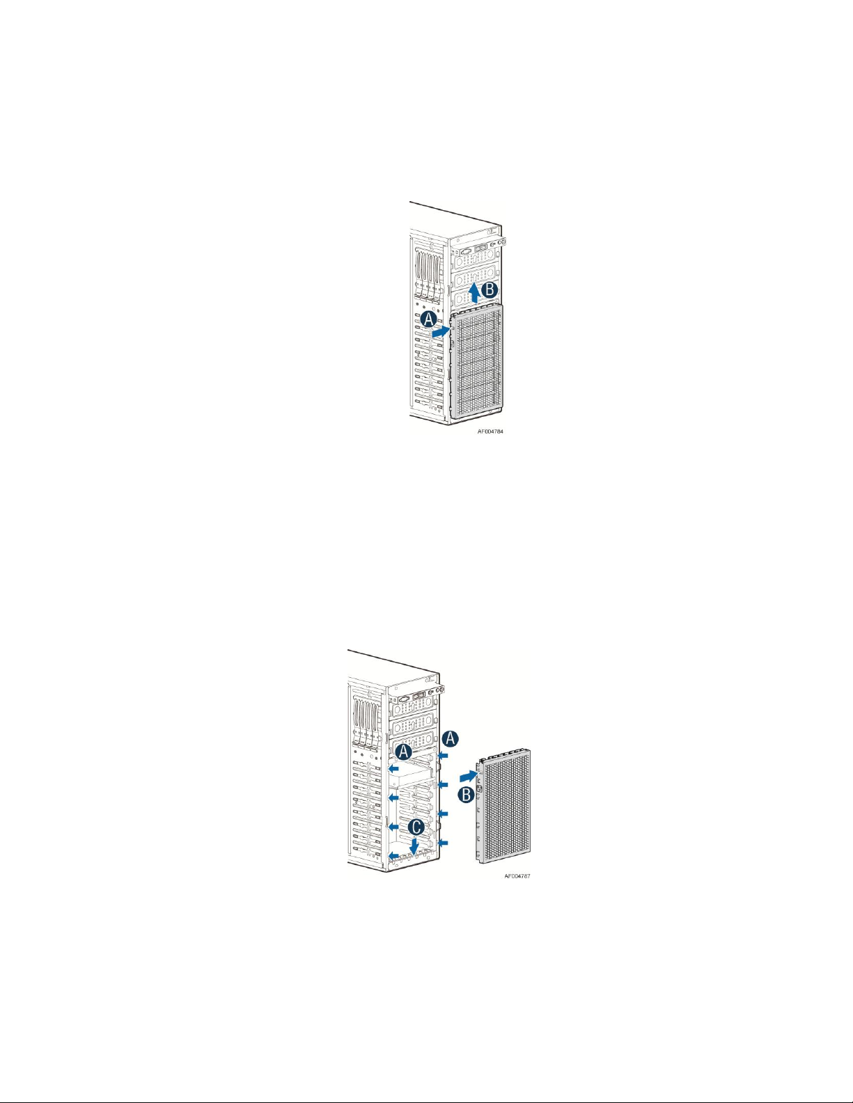
5. Lift the EMI shield (see letter A) and lift the EMI shield (see letter B) and move EMI shield outward
from the chassis.
Figure 22. Removing the EMI Shield
Installing the EMI Shield
1. Fit the edges of the EMI Shield against the sides of the chassis (see letter A).
2. While pressing the clip (see letter B), slide the EMI Shield downwards until the latches on the EMI
Shield are engaged with the chassis (see letter C).
Figure 23. Installing the EMI Shield
Intel® Server Chassis P4000S Service Guide 19
Page 32
Hardware Installations and Upgrades
Removing and Installing Fixed Hard Drive(s)
NOTE
This procedure applies only to the Intel® Server Chassis P4000S family with fixed HDD configuration.
Removing Fixed Hard Drive(s)
1. Observe the safety and ESD precautions at the beginning of this book.
2. Power down the server and unplug all peripheral devices and the AC power cable.
3. Remove the chassis cover. For instructions, see “Removing the Chassis Cover”.
4. Remove the front bezel if it is installed. For instructions, see “Removing the Front Bezel”.
5. Remove the Fixed HDD EMI shield. For instructions, see “Removing the Fixed HDD EMI Shield”.
6. Remove power and data cables from the hard drive connectors.
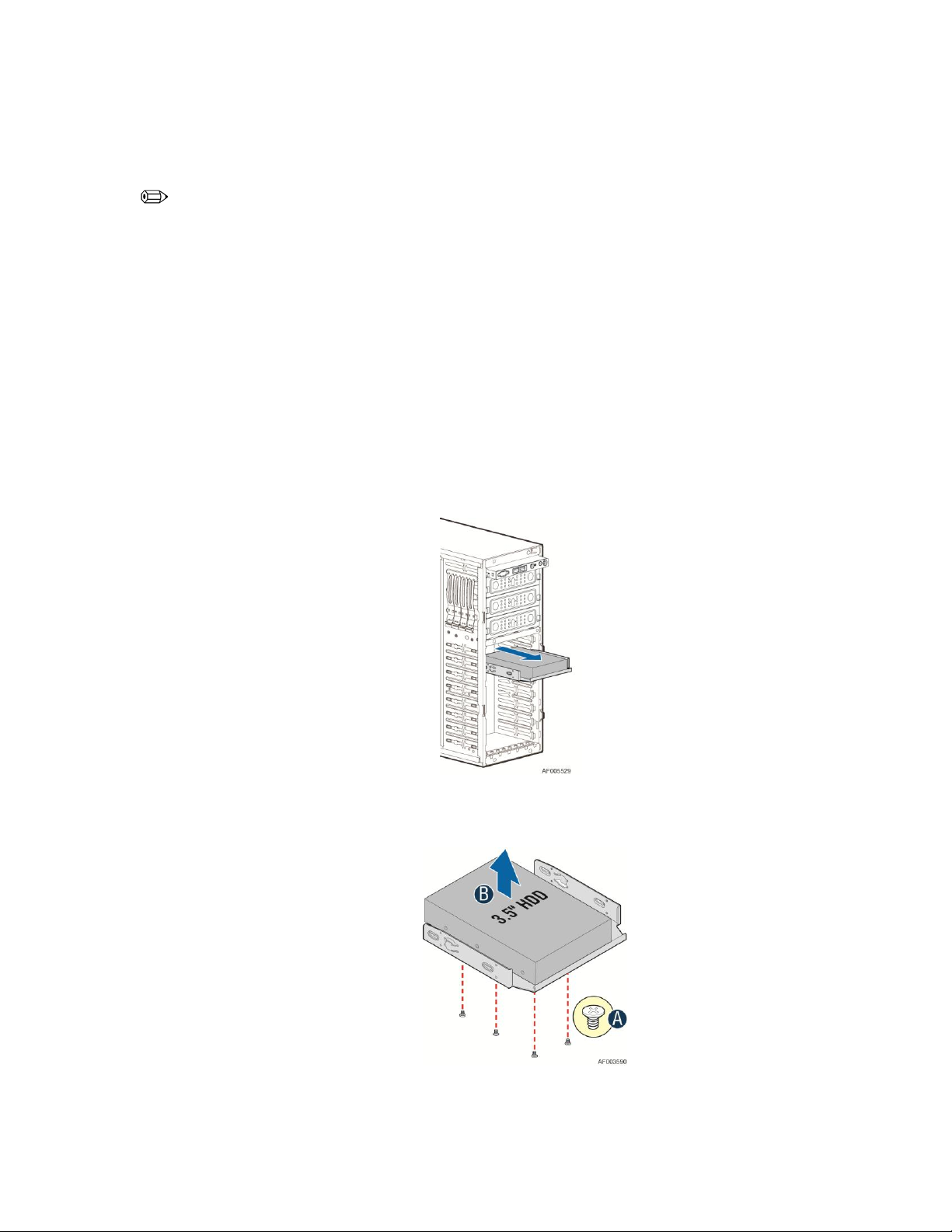
7. Pull out the HDD carrier tray.
Figure 24. Removing Fixed Hard Drives
8. Use screwdriver to release the 3.5'' or 2.5'' HDD from the carrier tray.
Figure 25. Removing the 3.5'' HDD from Fixed HDD tray
20 Intel® Server Chassis P4000S Service Guide
Page 33

Figure 26. Removing the 2.5'' HDD from Fixed HDD tray
9. Reinstall the HDD carrier tray into chassis.
Hardware Installations and Upgrades
Figure 27. Reinstalling the HDD Carrier Tray
10. Install the Fixed HDD EMI shield. For instructions, see “Installing the Fixed HDD EMI Shield”.
11. Install the front bezel. For instructions, see “Installing the Front Bezel”.
12. Install the air duct if the air duct is removed. For instructions, see “Removing the Airduct”.
13. Install the chassis cover. For instructions, see “Installing the Chassis Cover”.
14. Plug all peripheral devices and the AC power cable into the server.
15. Power up the server.
Installing Fixed Hard Drive(s)
1. Observe the safety and ESD precautions at the beginning of this book.
2. Power down the server and unplug all peripheral devices and the AC power cable.
3. Remove the chassis cover. For instructions, see “Removing the Chassis Cover”.
Intel® Server Chassis P4000S Service Guide 21
Page 34
Hardware Installations and Upgrades
4. Remove the front bezel if it is installed. For instructions, see “Removing the Front Bezel”.
5. Remove the Fixed HDD EMI shield. For instructions, see “Removing the Fixed HDD EMI Shield”.
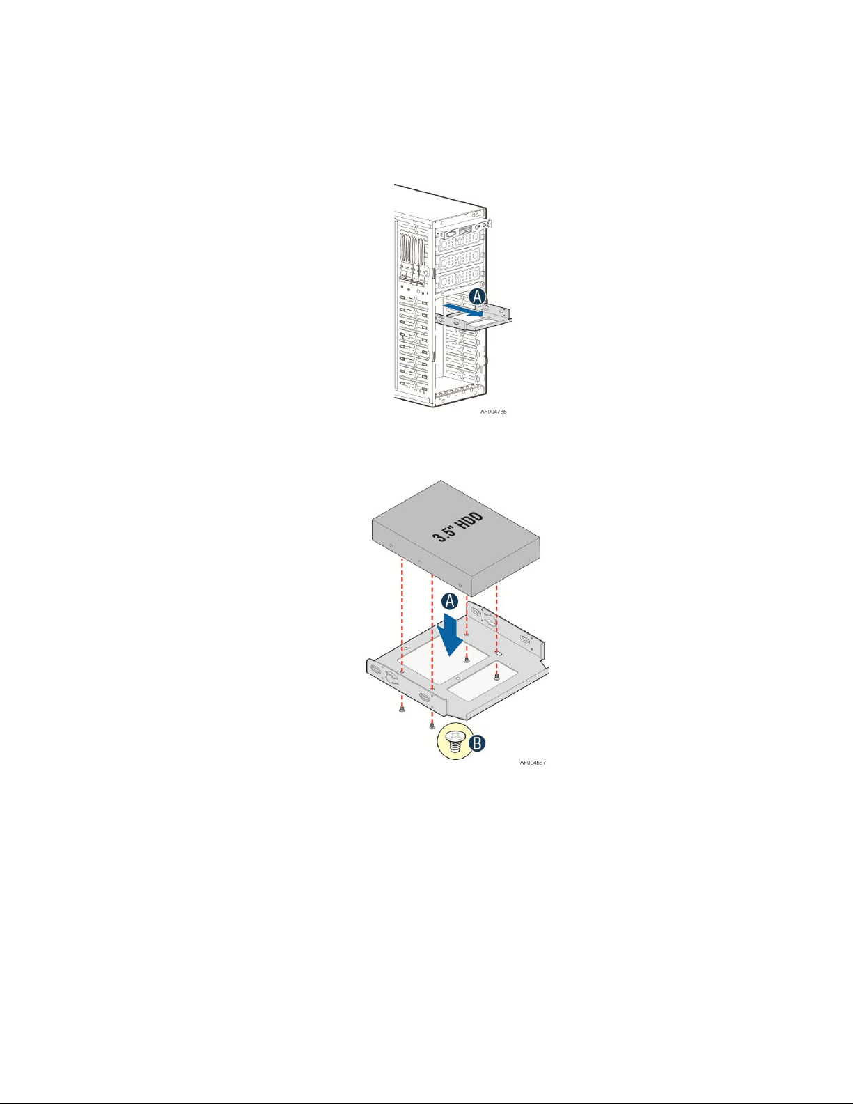
6. Pull out the HDD carrier tray.
Figure 28. Removing Fixed Hard Drive
7. Secure the 3.5'' or 2.5'' HDD on the HDD carrier tray with screws.
Figure 29. Securing the 3.5'' HDD on Fixed HDD Carrier Tray
22 Intel® Server Chassis P4000S Service Guide
Page 35

Figure 30. Securing the 2.5'' HDD on Fixed HDD Carrier Tray
8. Insert the HDD carrier tray into chassis.
Hardware Installations and Upgrades
Figure 31. Inserting the HDD Carrier Tray
9. Connect power and data cables on HDD.
10. Install the Fixed HDD EMI shield. For instructions, see “Installing the Fixed HDD EMI Shield”.
11. Install the front bezel. For instructions, see “Installing the Front Bezel”.
12. Install the air duct if the air duct is removed. For instructions, see “Installing the Airduct”
13. Install the chassis cover. For instructions, see “Installing the Chassis Cover”.
14. Plug all peripheral devices and the AC power cable into the server.
15. Power up the server.
Intel® Server Chassis P4000S Service Guide 23
Page 36

Hardware Installations and Upgrades
Removing and Installing 4x3.5'' Hot-swap Hard Drive
Cage Assembly
NOTE
This procedure applies only to the Intel® Server Chassis P4000S family with 4x3.5'' hot-swap hard disk
drive cage configuration.
Removing 4x3.5'' Hot-swap Hard Drive Cage with Backplane
1. Observe the safety and ESD precautions at the beginning of this book.
2. Power down the server and unplug all peripheral devices and the AC power cable.
3. Remove the chassis cover. For instructions, see “Removing the Chassis Cover”.
4. Remove the front bezel if it is installed. For instructions, see “Removing the Front Bezel”.
5. Disconnect the power and data cables to the backplane.
6. Use screwdriver to release the hot-swap hard drive cage (see letter A) from the chassis and remove
the hot-swap hard drive cage (see letter B).
Figure 32. Removing the 4x3.5'' HDD Cage
7. Lift the EMI shield (see letter A) and move EMI shield outward from the chassis (see letter B).
24 Intel® Server Chassis P4000S Service Guide
Page 37

Hardware Installations and Upgrades
Figure 33. Removing the EMI shield
Installing 4x3.5'' Hot-swap Hard Drive Cage with Backplane
CAUTION
It is critical that you connect the SAS/SATA data cables correctly from the SAS/SATA backplane to
your server board or RAID controller card. Failure to do so may result in data loss.
1. Observe the safety and ESD precautions at the beginning of this book.
2. Power down the server and unplug all peripheral devices and the AC power cable.
3. Remove the chassis cover. For instructions, see “Removing the Chassis Cover”.
4. Remove the front bezel if it is installed. For instructions, see “Removing the Front Bezel”.
5. Install the hot-swap EMI HDD shield under the hot-swap cage.
1) Fit the edges of the EMI Shiled against the sides of the chassis (see letter A).
2) While pressing the EMI shiled, slide the EMI Shield downwards until the latches on the EMI
shield are engaged with the chassis (see letter B).
Intel® Server Chassis P4000S Service Guide 25
Page 38

Hardware Installations and Upgrades
6. Install the 4x3.5'' Hot-Swap Hard Drive Cage.
Figure 34. Installing the EMI shield
1) Slide the 4x3.5'' Hot-Swap Drive Cage into the slot (see letter A).
2) Secure the Hard Drive Cage with the Screw (see letter B).
Figure 35. Installing the 4x3.5'' Hot-Swap Hard Drive Cage
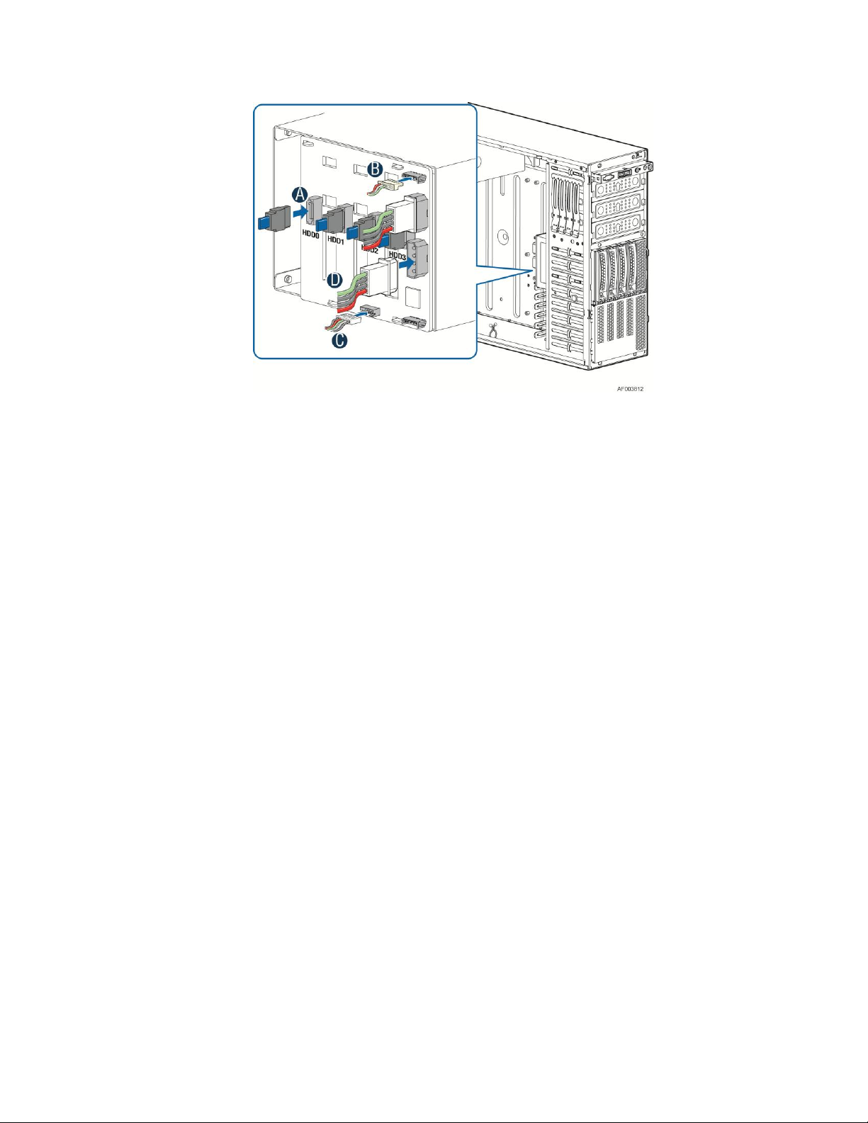
7. Make the backplane and server board/RAID controller card cable connections. Refer to the
documentation that came with your server board and/or RAID controller card for instructions on
connecting backplane cables to your server board or RAID controller card.
1) Connect data cables (letter A).
2) Connect an I2C_IN cable (letter B).
3) Connect an SGPIO cable (letter C).
4) Connect power cable (letter D).
26 Intel® Server Chassis P4000S Service Guide
Page 39
Hardware Installations and Upgrades
Figure 36. 4x3.5'' Hot Swap Backplane Cable Connections
8. Install the front bezel. For instructions, see “Installing the Front Bezel”.
9. Install the chassis cover. For instructions, see “Installing the Chassis Cover”.
10. Plug all peripheral devices and the AC power cable into the server.
11. Power up the server.
Removing and Installing 4x3.5'' Hot-swap Backplane
Removing 4x3.5'' Hot-swap Backplane
1. Observe the safety and ESD precautions at the beginning of this book.
2. Power down the server and unplug all peripheral devices and the AC power cable.
3. Remove the chassis cover. For instructions, see “Removing the Chassis Cover”.
4. Remove the front bezel if it is installed. For instructions, see “Removing the Front Bezel”.
5. Remove the 4x3.5'' Hot-swap Hard drives cage. For instructions, see “Removing 4x3.5'' Hot-swap
Hard Drive Cage”.
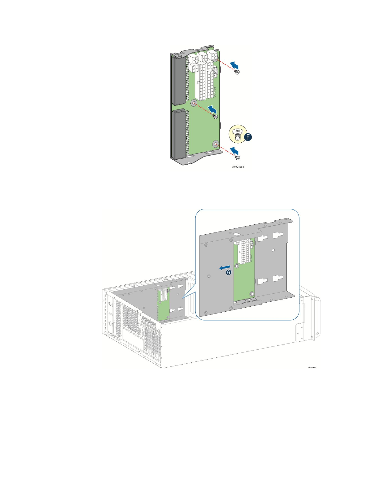
6. Remove the screw on the backplane (see letter A).
7. Push the backplane (see letter B) and remove the backplane from the chassis (see letter C).
Intel® Server Chassis P4000S Service Guide 27
Page 40

Hardware Installations and Upgrades
Figure 37. Removing 4x3.5'' Hot-swap Backplane
Installing 4x3.5'' Hot-swap Backplane
1. Observe the safety and ESD precautions at the beginning of this book.
2. Power down the server and unplug all peripheral devices and the AC power cable.
3. Remove the chassis cover. For instructions, see “Removing the Chassis Cover”.
4. Remove the front bezel if it is installed. For instructions, see “Removing the Front Bezel”.
5. Remove the 4x3.5'' Hot-swap Hard drives cage. For instructions, see “Removing 4x3.5'' Hot-swap
Hard Drive Cage”.
6. Attach the backplane to the back side of the hot-swap drive cage, and make sure the hooks on the
cage are insterted in the backplane holes (see letter A).
7. Push the backplane (see letter B) and secure the backplane with the screw (see letter C).
Figure 38. Installing 4x3.5” Hot-swap Backplane
28 Intel® Server Chassis P4000S Service Guide
Page 41
8. Install the 4x3.5'' Hot-swap Hard drives cage. For instructions, see “installing 4x3.5'' Hot-swap Hard
Drive Cage”.
9. Install the front bezel. For instructions, see “Installing the Front Bezel”.
10. Install the chassis cover. For instructions, see “Installing the Chassis Cover”.
11. Plug all peripheral devices and the AC power cable into the server.
12. Power up the server.
Installing Hot-swap Hard Drive
Installing 3.5" Hard Disk Drive
CAUTION
The 3.5" hard disk drive can be a SSD or SAS and SATA. Refer to your server board
or system documentation to determine SSD/SAS/SATA support for your server
system.
Hardware Installations and Upgrades
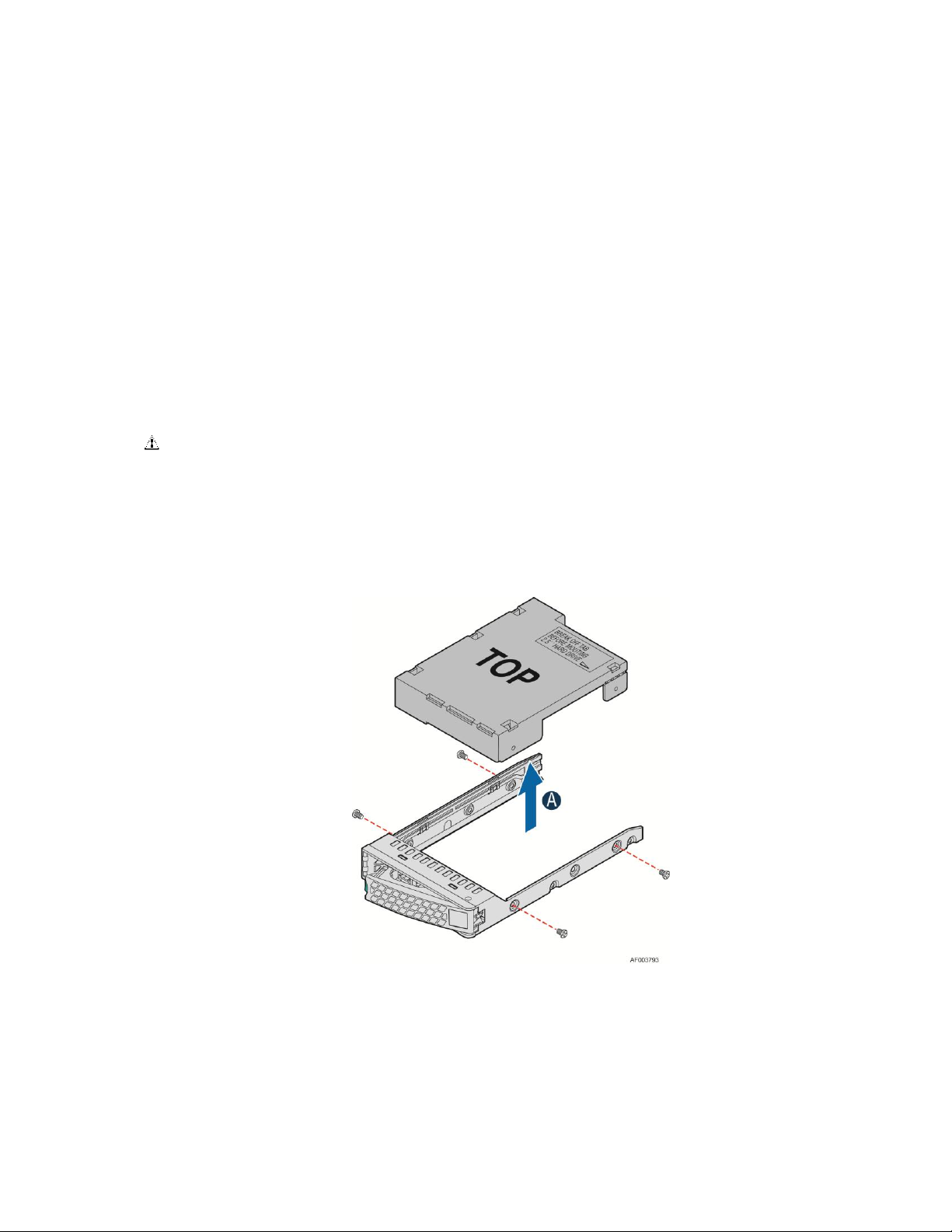
1. Remove the four screws securing the 2.5" HDD interface bracket and remove the 2.5" HDD interface
bracket.
Figure 39. Removing the 2.5" HDD interface bracket from Carrier
2. Install the 3.5" hard disk drive using the same four screws as shown. Make sure the connector end of the
drive matches the backplane connector.
Intel® Server Chassis P4000S Service Guide 29
Page 42

Hardware Installations and Upgrades
Figure 40. Installing the 3.5" HDD into the Carrier
Installing 2.5" Hard Disk Drive
CAUTION
The 2.5" hard disk drive can be a SSD or SAS and SATA. Refer to your server board
or system documentation to determine SSD/SAS/SATA support for your server
system.
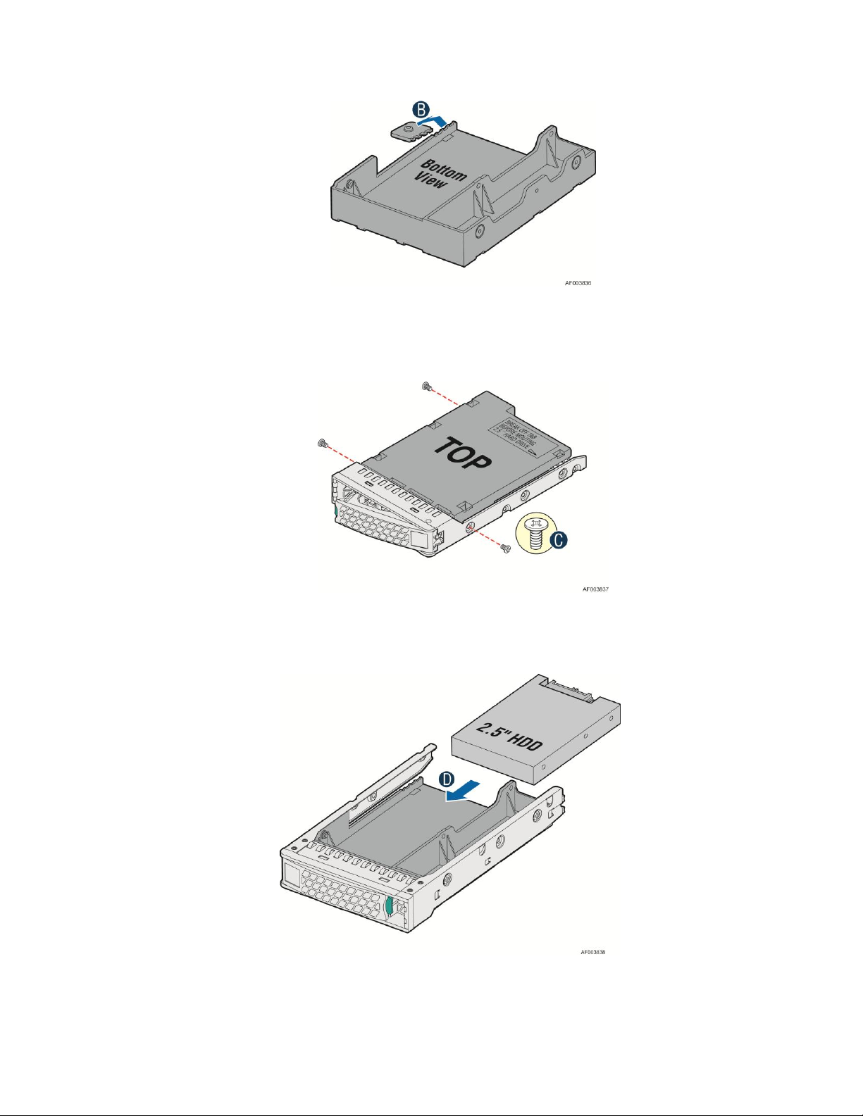
1. Remove the four screws securing the 2.5" HDD interface bracket and remove the 2.5" HDD interface
bracket.
Figure 41. Removing the 2.5" HDD interface bracket from Carrier
2. Break off the tab on the 2.5" HDD interface bracket (see letter B).
30 Intel® Server Chassis P4000S Service Guide
Page 43
Hardware Installations and Upgrades
Figure 42. Breaking off the tab on the bracket
3. Install the 2.5" Hard Drive Interface Bracket from top. Secure the bracket using the same screws as
shown.
Figure 43. Installing 2.5" HDD interface bracket into Carrier
4. Slide the 2.5" HDD into the bracket to align the screw holes with the right and left rail (See figure D).
Secure the hard disk drive using the screws for the 2.5’’ HDD (See figure E).
Intel® Server Chassis P4000S Service Guide 31
Page 44

Hardware Installations and Upgrades
Figure 44. Installing the 2.5" HDD into carrier
Removing and Installing Airduct
NOTE
Airduct may need to be ordered separately. See Configuration Guide of the server board for which airduct
work with your server board. The installation and/or removing airduct steps in below is generic. Please
see your board or system documents for specific instructions about installing and/or removing airduct.
Installing the Airduct
1. Observe the safety and ESD precautions at the beginning of this book.
2. Power down the server and unplug all peripheral devices and the AC power cable.
3. Remove the chassis cover. For instructions, see “Removing the Chassis Cover”.
4. Install the airduct by aligning the air duct and CPU fans (see letter A) and ensure the tab on air duct is
engaged in its snap-in bracket.(see letter B).
32 Intel® Server Chassis P4000S Service Guide
Page 45

Hardware Installations and Upgrades
Figure 45. Installing the Airduct
Removing the Airduct
1. Observe the safety and ESD precautions at the beginning of this book.
2. Power down the server and unplug all peripheral devices and the AC power cable.
3. Remove the chassis cover. For instructions, see “Removing the Chassis Cover”.
4. Push the tab outward to disengage the tab from its snap-in blacket (see letter A).
5. Grasp the air duct and remove (see letter B).
Figure 46. Removing the Airduct
Intel® Server Chassis P4000S Service Guide 33
Page 46

Hardware Installations and Upgrades
Removing and Installing the Fixed Power Supply
WARNING
Hazardous voltage, current, and energy levels are present inside the power supply. There are no
user-serviceable parts inside it; servicing should be done by technically qualified personnel.
Removing the Fixed Power Supply
1. Observe the safety and ESD precautions at the beginning of this book.
2. Power down the server and unplug all peripheral devices and the AC power cable.
3. Remove the chassis cover. For instructions, see “Removing the Chassis Cover”.
4. Disconnect all internal power cables from chassis components and server board.
5. Rotate the power supply locking device counter-clockwise (see letter A) and remove the fixed power
supply (see letter B).
Figure 47. Removing Fixed Power Supply
Installing the Fixed Power Supply
1. Insert new fixed power supply and rotate the power supply locking device clockwise (see letter A and
B).
34 Intel® Server Chassis P4000S Service Guide
Page 47

Hardware Installations and Upgrades
Figure 48. Installing Fixed Power Supply
2. Reconnect power cables to other chassis components as appropriate.
3. Install the chassis cover. For instructions, see “Installing the Chassis Cover”.
4. Plug all peripheral devices and the AC power cable into the server.
5. Power up the server.
Installing an Additional Hot-swap Power Supply
Module
NOTE
This install procedure only applies to a chassis with redundant power supply capability.
WARNING
Hazardous voltage, current, and energy levels are present inside the power supply. There are no
user-serviceable parts inside it; servicing should be done by technically qualified personnel.
1. Observe the safety and ESD precautions at the beginning of this book.
2. Insert finger into finger hole in middle of filler panel and remove the filler panel from chassis.
Intel® Server Chassis P4000S Service Guide 35
Page 48
Hardware Installations and Upgrades
Figure 49. Removing Power Supply Filler Panel
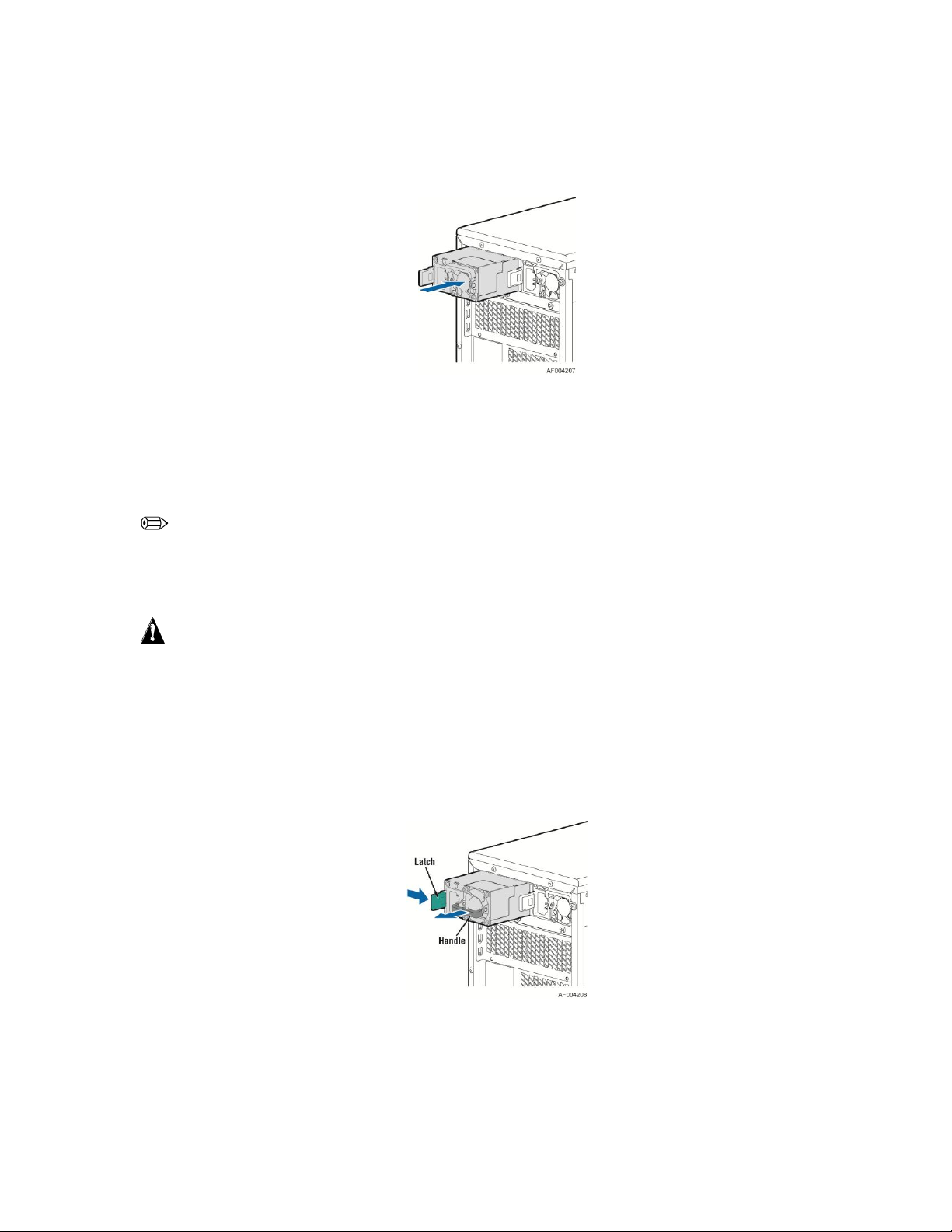
3. Insert the power supply module into the power supply cage and push all the way until it clicks into
place.
Figure 50. Installing Additional Hot-swap Power Supply Module
Replacing a Hot Swap Power Supply Module
NOTE
This install procedure only applies to a chassis with redundant power supply capability.
WARNING
Hazardous voltage, current, and energy levels are present inside the power supply. There are no
user-serviceable parts inside it; servicing should be done by technically qualified personnel.
1. Observe the safety and ESD precautions at the beginning of this book.
2. Remove power cable from defective power supply.
3. Press up on green latch in the direction shown while pulling on handle to remove hot swap power supply
from chassis.
Figure 51. Removing Hot-swap Power Supply Module from Chassis
4. Insert new power supply module into the power supply cage and push all the way until it clicks into place.
36 Intel® Server Chassis P4000S Service Guide
Page 49

Hardware Installations and Upgrades
Figure 52. Installing Hot-swap Power Supply Module into Chassis
Replacing the Power Distribution Board for 460W
PSUs
WARNING
Hazardous voltage, current, and energy levels are present inside the power supply. There are no
user-serviceable parts inside it; servicing should be done by technically qualified personnel.
1. Observe the safety and ESD precautions at the beginning of this book.
2. Power down the server and unplug all peripheral devices and the AC power cable.
3. Remove the chassis cover. For instructions, see “Removing the Chassis Cover”.
4. Remove the air duct. For instructions, see “Installing the Airduct”.
5. Disconnect all internal power cables from chassis components and server board.
6. If present, press on green latch in the direction shown while pulling on handle to remove power
supply from chassis. Repeat this step for the second hot-swap power supply if it is installed.
Figure 53. Removing Hot-swap Power Supply Module from Chassis
7. Loosen screws securing the bracket with power distribution board to the chassis (see letter A and B).
Intel® Server Chassis P4000S Service Guide 37
Page 50

Hardware Installations and Upgrades
Figure 54. Loosening the Bracket with Power Distribution Board from Chassis
8. Push the bracket forward to release the latch which secure the bracket then pull out the bracket from
the chassis (see letter C).
Figure 55. Removing the Bracket with Power Distribution Board from Chassis
9. Loosen screws securing the power distribution board to the bracket, and then remove it from the
bracket (see letter D).
38 Intel® Server Chassis P4000S Service Guide
Page 51

Hardware Installations and Upgrades
Figure 56. Removing the Power Distribution Board from Bracket
10. Slide the new power distribution board to the bracket (see letter E) and secure the new power
distribution board to the bracket using the same screws (see letter F).
Figure 57. Sliding the New Power Distribution Board in Bracket
Intel® Server Chassis P4000S Service Guide 39
Page 52
Hardware Installations and Upgrades
Figure 58. Securing the New Power Distribution Board in Bracket
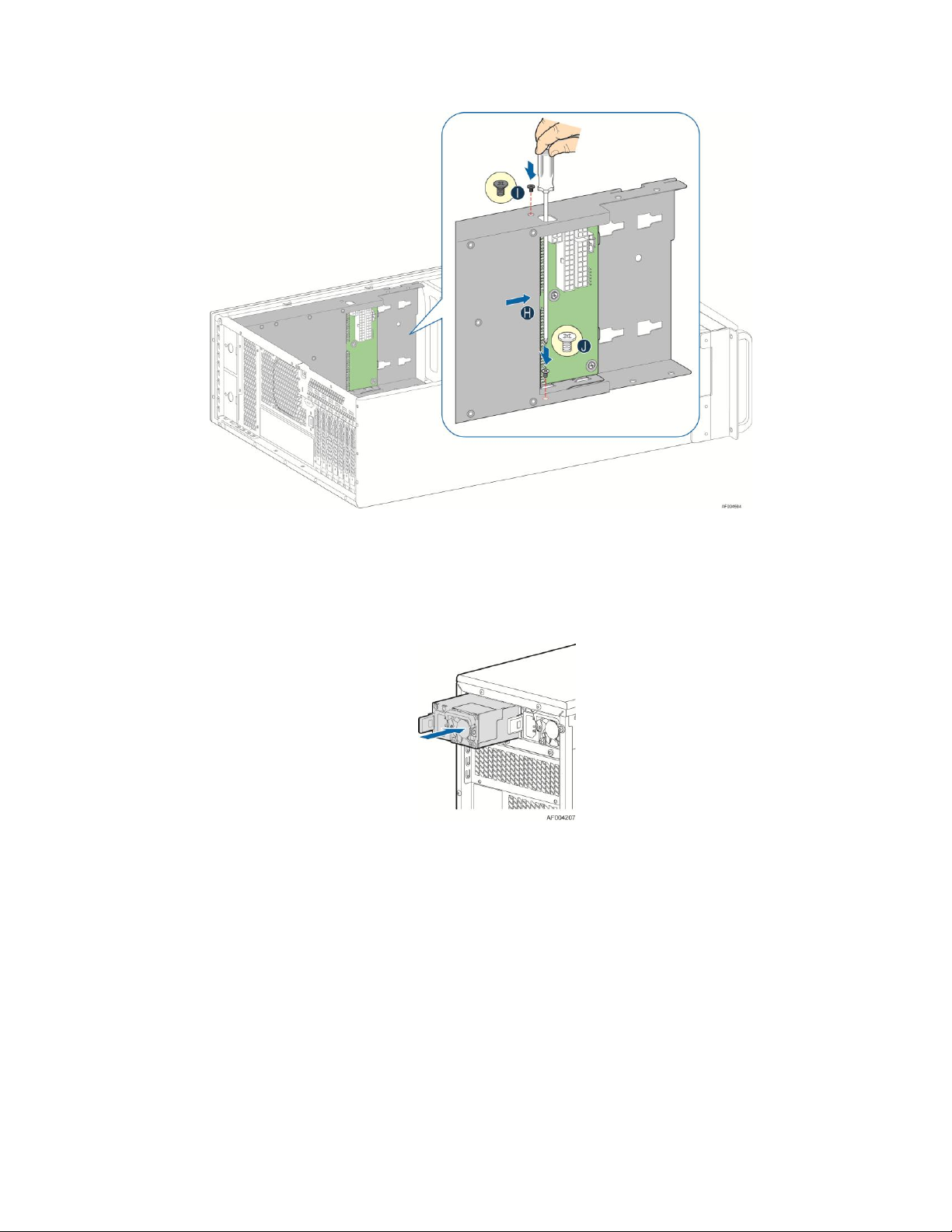
11. Slide the bracket with the new power distribution board all the way into the power supply cage (see
letter G).
Figure 59. Sliding the Bracket into Power Supply Cage
12. Then pull back until the latch on the bracket is engaged with the power supply cage and make sure
the screw holes on the bracket is aligned with the screw holes on power supply cage (see letter H).
And then secure the bracket with the screws (see letter I and J).
40 Intel® Server Chassis P4000S Service Guide
Page 53
Hardware Installations and Upgrades
Figure 60. Securing the Bracket into Power Supply Cage
13. Reconnect the power cables as appropriate.
14. Insert the power supply(s) into the power supply cage and push all the way until it clicks into place.
Figure 61. Installing Hot-swap Power Supply Module into Chassis
15. Reinstall the air duct. For instructions, see “Installing the Airduct”.
16. Re-install the chassis cover. For instructions, see “Installing the Chassis Cover’.
17. Plug all peripheral devices and the AC power cable into the server.
18. Power up the server.
Intel® Server Chassis P4000S Service Guide 41
Page 54

Hardware Installations and Upgrades
Removing and Installing the Rear Fixed Fan
NOTE
This procedure applies only to the Intel® Server chassis P4304XXSFCN and P4304XXSHCN.
Removing the Rear Fixed Fan
1. Observe the safety and ESD precautions at the beginning of this book.
2. Power down the server and unplug all peripheral devices and the AC power cable.
3. Remove the chassis cover. For instructions, see “Removing the Chassis Cover”.
4. Disconnect the appropriate fan power cable from the server board.
5. Locate the four nylon rivets on the four corners of the Fan assembly. From the inside of chassis, push
the push-pins (inner part of the rivit) outward, then remove the sleeves (outer part of the rivit). See
letter A and B.
6. Remove the Fan and the rear vent cover under the Fan (see letter C and D).
Figure 62. Removing the Rear Fixed Fan
Installing the Rear Fixed Fan
1. Observe the safety and ESD precautions at the beginning of this book.
2. Power down the server and unplug all peripheral devices and the AC power cable.
3. Remove the chassis cover. For instructions, see “Removing the Chassis Cover”.
4. Press the rear vent cover and the fan against the inner side of the chassis rear, adjust until the rivet
holes on the chassis, rear vent cover and the fan are aligned with each other (see letter A and B).
5. While holding the rear vent cover and fan, insert the sleeves of the nylon rivet into the rivet holes from
outside of the chassis. Push the push-pins of the nylon rivet into the sleeves (see letter C and D).
42 Intel® Server Chassis P4000S Service Guide
Page 55
Hardware Installations and Upgrades
6. Connect fan power cable to the server/workstation board. See the Quick Start User’s Guide or
Service Guide provided with your Intel server/workstation board for appropriate connection location.
Figure 63. Installing the Rear Fixed Fan
Removing and Installing the Front Fixed Fan
NOTE
This procedure applies only to the Intel® Server chassis P4304XXSFEN, P4304XXSHEN, P4304XXSFDR,
P4304XXSHDR, P4304XXSFDN, and P4304XXSHDN.
Removing the Front Fixed Fan
1. Observe the safety and ESD precautions at the beginning of this book.
2. Power down the server and unplug all peripheral devices and the AC power cable.
3. Remove the chassis cover. For instructions, see “Removing the Chassis Cover”.
4. Remove the airduct if it is installed. For instructions, see “Removing the Airduct”.
5. Disconnect the appropriate fan power cable from the server board.
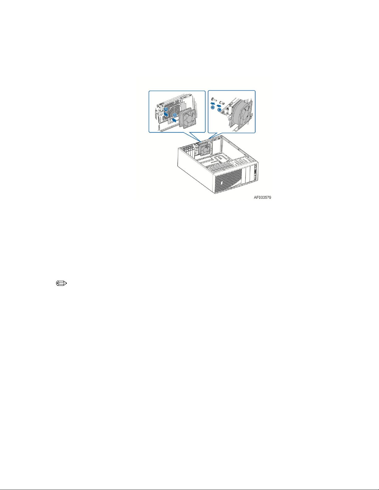
6. Remove the two screws which secured the fan assembly, and take the fan assembly out (see letter
A).
7. Locate the four nylon rivets on the four corners of the fan assembly. Remove all the four nylon rivets
from the rear vent cover to take the fan out (see letter B and C).
Intel® Server Chassis P4000S Service Guide 43
Page 56

Hardware Installations and Upgrades
Figure 64. Removing the Front Fixed Fan
Installing the Front Fixed Fan
1. Observe the safety and ESD precautions at the beginning of this book.
2. Power down the server and unplug all peripheral devices and the AC power cable.
3. Remove the chassis cover. For instructions, see “Removing the Chassis Cover”.
4. Remove the airduct if it is installed. For instructions, see “Removing the Airduct”.
5. While holding the rear vent cover and fan, insert the sleeves of the nylon rivet into the rivet. Push the
nylon push-pins of the nylon rivet into the sleeves (see letter A and B).
6. Align the fan assembly with the two screw-holes insdie the chassis and secure the fan assembly with
the screws (see letter C).
44 Intel® Server Chassis P4000S Service Guide
Page 57

Hardware Installations and Upgrades
Figure 65. Installing the Front Fixed Fan
7. Connect fan power cable to the server/workstation board. See the Quick Start User’s Guide or
Service Guide provided with your Intel server/workstation board for appropriate connection location.
Intel® Server Chassis P4000S Service Guide 45
Page 58

Hardware Installations and Upgrades
Removing and Installing the PCI Card Guide
Removing PCI Card Guide
NOTE
When full length PCI card is plugged, PCI Card Guide is needed to secure the PCI Card.
1. Observe the safety and ESD precautions at the beginning of this book.
2. Power down the server and unplug all peripheral devices and the AC power cable.
3. Remove the chassis cover. For instructions, see “Removing the Chassis Cover”.
4. Unplug all the PCI cards if there are PCI cards plugged in. When removing a full-length add-in card,
you must pull back the latch on the plastic card guide at the front of the chassis to release the card
from the card guide. For instructions, see “Removing the PCI Add-in Board(s).
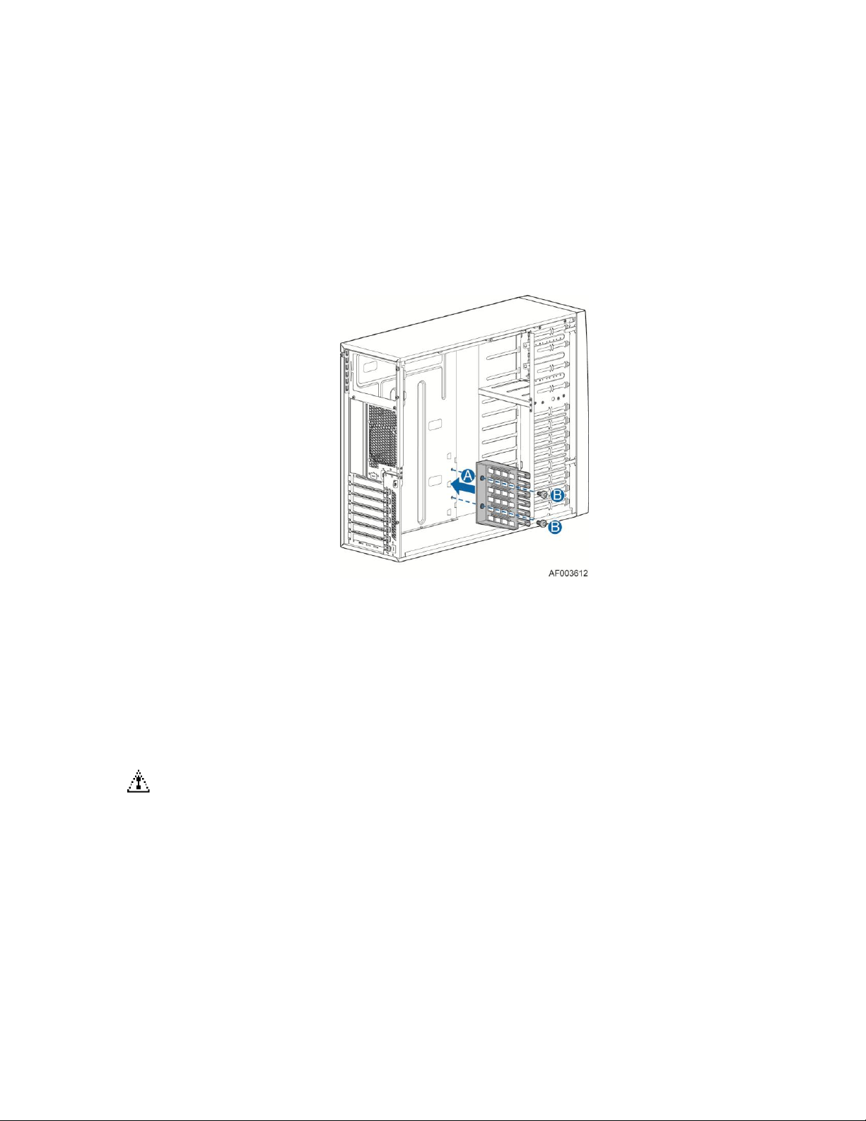
5. Remove the two screws securing the PCI card guide (See letter A).
6. Remove the PCI card guide (See letter B and letter C).
Figure 66. Removing the PCI Guard
Installing PCI Card Guide
NOTE
Required only when full length PCI card is plugged.
1. Observe the safety and ESD precautions at the beginning of this book.
2. Power down the server and unplug all peripheral devices and the AC power cable.
46 Intel® Server Chassis P4000S Service Guide
Page 59
Hardware Installations and Upgrades
3. Remove the chassis cover. For instructions, see “Removing the Chassis Cover”.
4. Unplug all the PCI cards if there are PCI cards plugged in. For instructions, see “Removing the PCI
Add-in Board(s).
5. Insert tabs on left slide of PCI Card Guide into slots in chassis (See letter A).
6. Secure the PCI Card Guide with the screws (See letter B).
Figure 67. Installing the PCI Guard
Removing and Installing PCI Add-in Board(s)
Removing PCI Add-in Board(s)
CAUTION
When removing a full-length add-in card, you must pull back the latch on the plastic card guide at
the front of the chassis to release the card from the card guide.
1. Observe the safety and ESD precautions at the beginning of this book.
2. Power down the server and unplug all peripheral devices and the AC power cable.
3. Remove the chassis cover. For instructions, see “Removing the Chassis Cover”.
4. Remove any cables attached to the add-in card, if necessary.
5. From inside of chassis, press open the back panel PCI add-in board retentaion device (see letter A).
Intel® Server Chassis P4000S Service Guide 47
Page 60

Hardware Installations and Upgrades
6. Firmly grab the PCI add-in board by its top edge or outer corners and remove from the expansion slot
on the server board (see letter B).
Figure 68. Removing the PCI add-in card
7. Install the PCI blank filler and close the PCI add-in card retention device.
8. Install the chassis cover. For instructions, see “Installing the Chassis Cover”.
9. Plug all peripheral devices and the AC power cable into the server.
10. Power up the server.
Installing PCI Add-in Board(s) for P4304XXSFCN and
P4304XXSHCN
CAUTION
You may want to install an operating system before installing any add-in boards.
Do not overload the server board by installing add-in boards that draw excessive current.
Add-in boards can be extremely sensitive to ESD and always require careful handling. After
removing the board from its protective wrapper, place it component side up on a grounded, staticfree surface. Do not slide the board over any surface.
1. Observe the safety and ESD precautions at the beginning of this book.
2. Power down the server and unplug all peripheral devices and the AC power cable.
3. Remove the chassis cover. For instructions, see “Removing the Chassis Cover”.
4. Install the PCI card guide if full length PCI card is to be installed. For instructions, see “Install PCI
Card Guide” (Only needed when full length PCI card is plugged).
5. Remove the PCI slot shield (see letter A) by pushing from the shield out from inside the chassis.
48 Intel® Server Chassis P4000S Service Guide
Page 61

Hardware Installations and Upgrades
Figure 69. Preparing Chassis for Addition of PCI add-in board
6. From inside of chassis, press open the back panel PCI add-in board retentaion device (see letter B).
Figure 70. Open the back panel PCI add-in board retentaion device
7. Remove the PCI add-in board from its protective wrapper. Be careful not to touch the components or
gold edge connectors. Place the add-in board on an anti-static surface. Record the type and serial
number of the add-in board in your equipment log. Set the jumpers or switches on the board
according to the manufacturer’s instructions.
8. Hold the PCI add-in board by its top edge or upper corners. Firmly press the add-in board into an
expansion slot on the server board (see letter C in the following figure). Close the back panel PCI
add-in card retention device (see letter D).
Intel® Server Chassis P4000S Service Guide 49
Page 62

Hardware Installations and Upgrades
Figure 71. Installing PCI Add-in Board
9. Attach cables if necessary.
10. Install the chassis cover. For instructions, see “Installing the Chassis Cover”.
11. Plug all peripheral devices and the AC power cable into the server.
12. Power up the server.
Installing non-Full Length PCI Add-in Board(s) for
P4304XXSFEN/P4304XXSHEN/P4304XXSFDR/P4304XXSHDR/P
4304XXSFDN/P4304XXHDN
CAUTION
You may want to install an operating system before installing any add-in boards.
Do not overload the server board by installing add-in boards that draw excessive current.
Add-in boards can be extremely sensitive to ESD and always require careful handling. After
removing the board from its protective wrapper, place it component side up on a grounded, staticfree surface. Do not slide the board over any surface.
1. Observe the safety and ESD precautions at the beginning of this book.
2. Power down the server and unplug all peripheral devices and the AC power cable.
3. Remove the chassis cover. For instructions, see “Removing the Chassis Cover”.
4. Remove the PCI slot shield (see letter A) by pushing from the shield out from inside the chassis.
50 Intel® Server Chassis P4000S Service Guide
Page 63

Hardware Installations and Upgrades
Figure 72. Preparing Chassis for Addition of PCI add-in board
5. From inside of chassis, press open the back panel PCI add-in board retentaion device (see letter B).
Figure 73. Open the back panel PCI add-in board retentaion device
6. Remove the PCI add-in board from its protective wrapper. Be careful not to touch the components or
gold edge connectors. Place the add-in board on an anti-static surface. Record the type and serial
number of the add-in board in your equipment log. Set the jumpers or switches on the board
according to the manufacturer’s instructions.
7. Hold the PCI add-in board by its top edge or upper corners. Firmly press the add-in board into an
expansion slot on the server board (see letter C in the following figure). Close the back panel PCI
add-in card retention device (see letter D).
Intel® Server Chassis P4000S Service Guide 51
Page 64
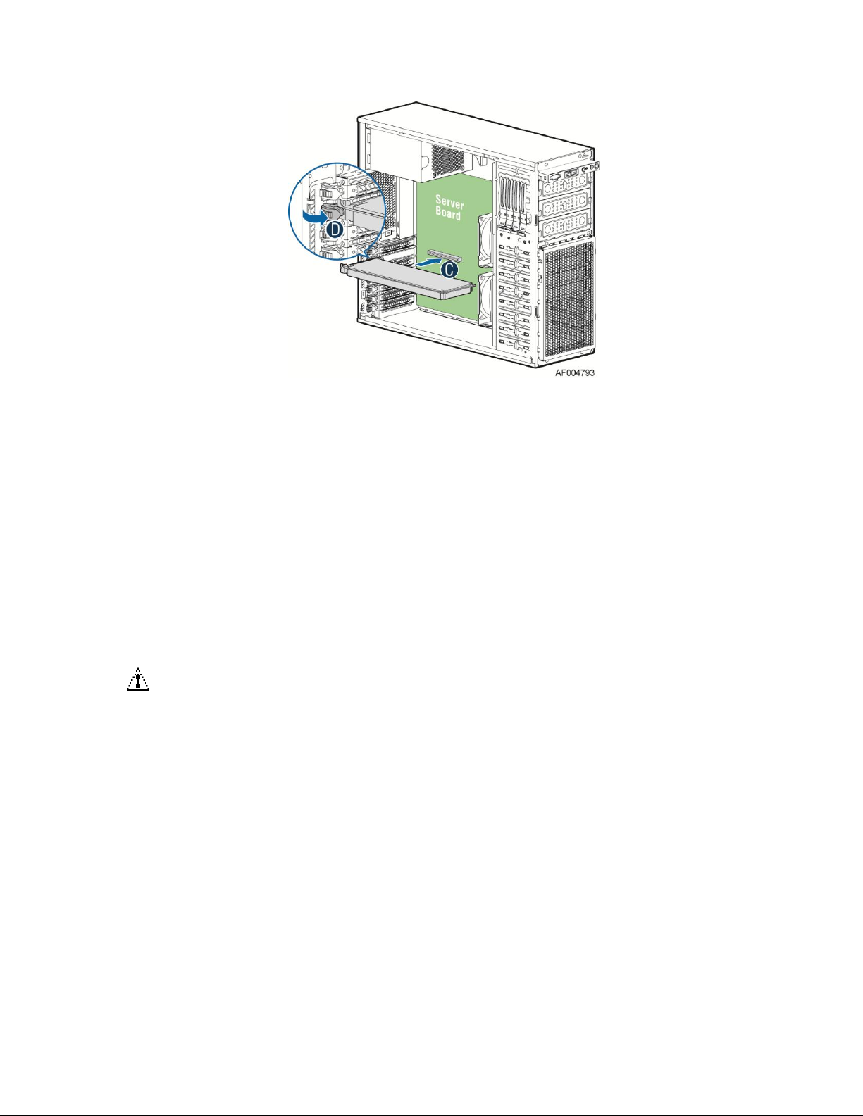
Hardware Installations and Upgrades
Figure 74. Installing PCI Add-in Board
8. Attach cables if necessary.
9. Install the chassis cover. For instructions, see “Installing the Chassis Cover”.
10. Plug all peripheral devices and the AC power cable into the server.
11. Power up the server.
Installing Full Length PCI Add-in Board(s) for
P4304XXSFEN/P4304XXSHEN/P4304XXSFDR/P4304XXSHDR/P
4304XXSFDN/P4304XXHDN
CAUTION
You may want to install an operating system before installing any add-in boards.
Do not overload the server board by installing add-in boards that draw excessive current.
Add-in boards can be extremely sensitive to ESD and always require careful handling. After
removing the board from its protective wrapper, place it component side up on a grounded, staticfree surface. Do not slide the board over any surface.
1. Observe the safety and ESD precautions at the beginning of this book.
2. Power down the server and unplug all peripheral devices and the AC power cable.
3. Remove the chassis cover. For instructions, see “Removing the Chassis Cover”.
4. Remove the airduct if it is installed. For instruction, see “Removing the Aircut”.
5. Remove the PCI zone system fan (see B in below figure for the PCI zone system fan). For instruction,
see “Removing the Front Fixed Fan”
52 Intel® Server Chassis P4000S Service Guide
Page 65
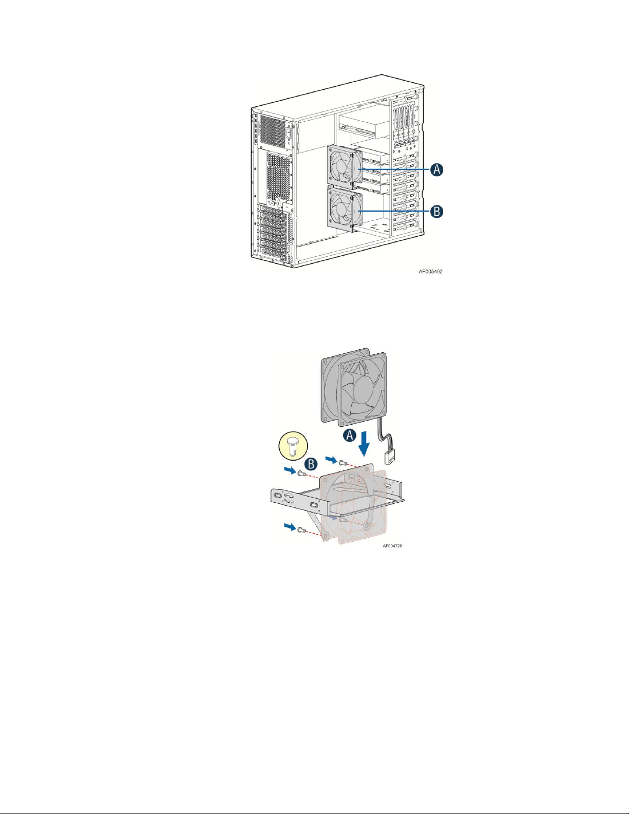
Hardware Installations and Upgrades
A. CPU Zone System Fan
B. PCI Zone System Fan
Figure 75. Front fixed system fans
6. Assembly the fan using the fan kit. (The fan kit needs to be ordered separately).
Figure 76. Assemblying the fan in fan kit
7. For chassis that supports fixed drive, remove the fixed HDD EMI shield, and then insert the fan
assembly from front side of the chassis.
For chassis with hot-swap drive cage, remove the drive cage and the EMI cover, insert the fan
assembly, and then install the EMI cover and the drive cage back.
Intel® Server Chassis P4000S Service Guide 53
Page 66
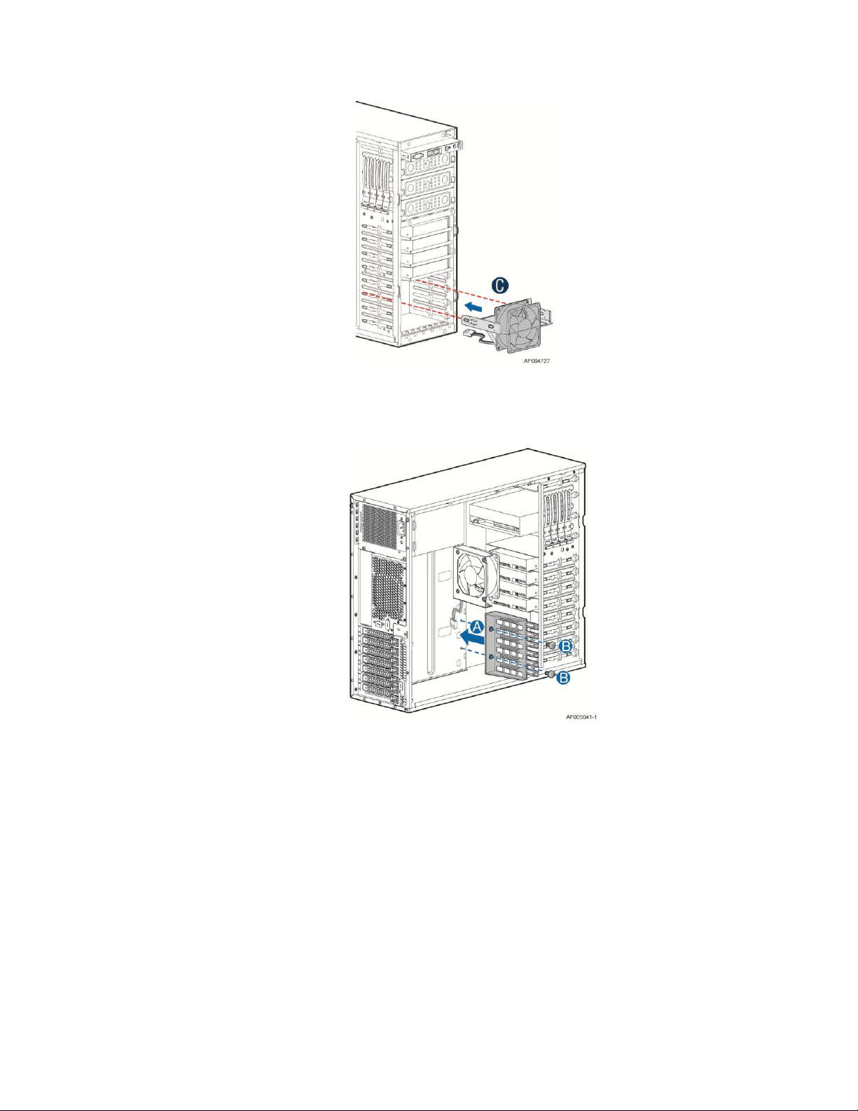
Hardware Installations and Upgrades
Figure 77. Insert the fan assembly from front of the chassis
8. Install the PCI card guide. For instructions, see “Installing PCI Card Guide” (Only needed when full
length PCI card is plugged).
Figure 78. Installing the PCI Guard
9. Install the PCI card. For instructions, see “Installing non-Full Lenth PCI Add-in Board(s) for
P4304XXSFEN/P4304XXSHEN/P4304XXSFDR/P4304XXSHDR/P4304XXSFDN/P4304XXSHDN”.
Removing and Installing the Chassis Feet
Removing the Chassis Feet
1. Observe the safety and ESD precautions at the beginning of this book.
2. Power down the server and unplug all peripheral devices and the AC power cable.
54 Intel® Server Chassis P4000S Service Guide
Page 67
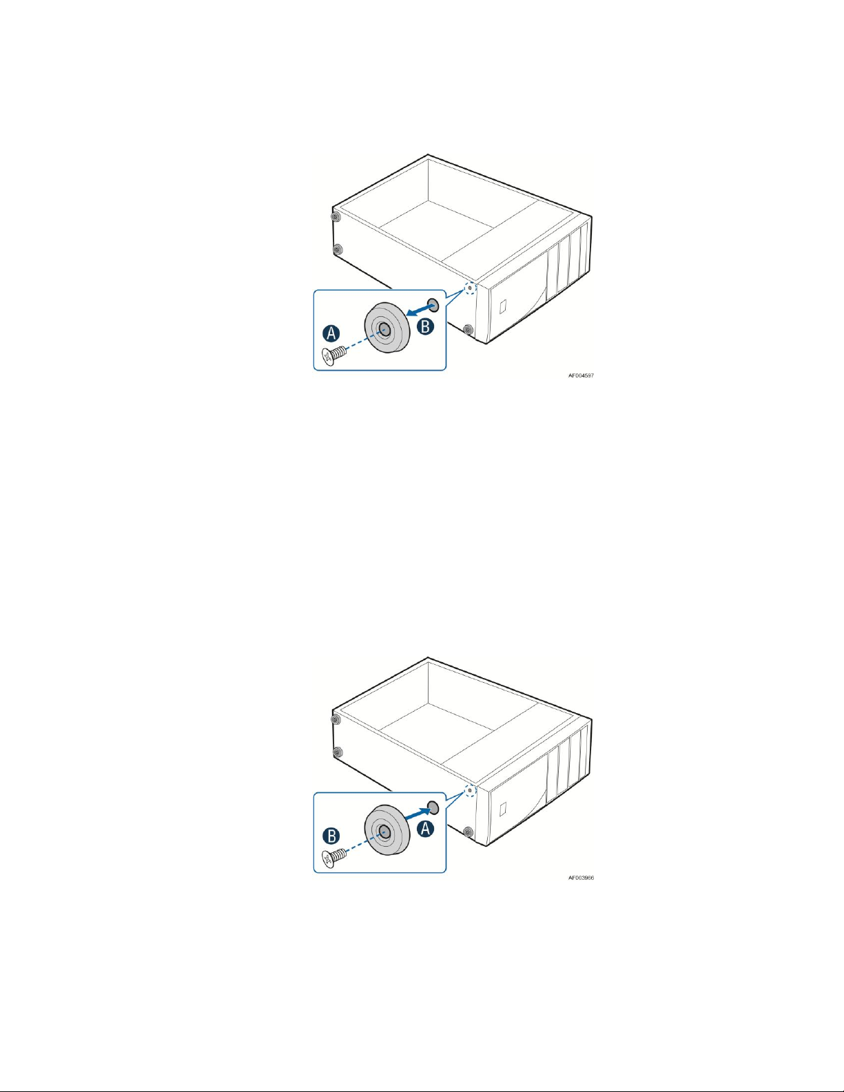
Hardware Installations and Upgrades
3. Lay the chassis down on its right side.
4. Loose the screws securing the rubber foot to the chassis and then remove the rubber foot from chassis.
Figure 79. Removing the Chassis Feet
5. Repeat above steps until all four feet are removed.
Installing the Chassis Feet
1. Observe the safety and ESD precautions at the beginning of this book.
2. Power down the server and unplug all peripheral devices and the AC power cable.
3. Lay the chassis down on its right side.
4. Insert rubber foot into chassis hole (see letter A).
5. Secure foot by inserting screw through the rubber foot (see letter B).
6. Repeat above steps until all four feet are installed.
Figure 80. Installing the Chassis Feet
7. Put chassis in the upright position.
8. Reconnect all peripheral devices and the AC power cable to the server. Power up the server.
Intel® Server Chassis P4000S Service Guide 55
Page 68

Hardware Installations and Upgrades
Removing and Installing the Front Panel Tray
CAUTION
The front panel is NOT hot swappable. Before removing or replacing the control panel, you must
first take the server out of service, turn off all peripheral devices connected to the system, turn off
the system by pressing the power button, and unplug the AC power cord from the system or wall
outlet.
Removing the Front Control Panel Tray
1. Observe the safety and ESD precautions at the beginning of this book.
2. Power down the server and unplug all peripheral devices and the AC power cable.
3. Remove the chassis cover. For instructions, see “Removing the Chassis Cover”.
4. Remove the front bezel if it is installed. For instructions, see “Removing the Front Bezel”.
5. Disconnect the front panel cable, USB cable from the server board
Figure 81. Disconnecting the Cables from the Server Board
6. Loose the front panel cable and USB cable from the wire clip on chassis
7. Press the latch at the sides of the front panel (see letter A) and carefully slide the front panel out (see
letter B).
CAUTION
Do not slide the front panel out far from the front of the chassis before you disconnect the
instruction cable from the front panel board.
56 Intel® Server Chassis P4000S Service Guide
Page 69

Hardware Installations and Upgrades
Figure 82. Sliding the Front Panel Tray out from the Chassis
8. Slide the front panel out from the front of the chassis to the place (see Letter C) so that you can reach
the front panel and USB cable connectors at the rear of the front panel. Then disconnect the front
panel cable and intrusion switch cable from the front panel board (see Letter D).
Figure 83. Disconnecting the Cables from Front Panel Board
9. Slide the front panel tray out.
Installing the Fron Panel Tray
1. Observe the safety and ESD precautions at the beginning of this book.
2. Power down the server and unplug all peripheral devices and the AC power cable.
3. Remove the chassis cover. For instructions, see “Removing the Chassis Cover”.
4. Remove the front bezel if it is installed. For instructions, see “Removing the Front Bezel”.
5. Attach the front panel cable and the chassis intrusion cable (see letter A) to the front panel board.
Intel® Server Chassis P4000S Service Guide 57
Page 70

Hardware Installations and Upgrades
Figure 84. Connecting the Cables to the Front Panel Board
6. Slide the front panel tray in chassis
Figure 85. Installing the Front Panel Tray in Chassis
7. Connect the front panel and USB cables to server board.
58 Intel® Server Chassis P4000S Service Guide
Page 71

Hardware Installations and Upgrades
Figure 86. Connecting the Cables to Server Board the Front Panel Tray in Chassis
8. Install the front bezel. For instructions, see “Removing and Installing the Front Bezel”.
9. Install the chassis cover. For instructions, see “Installing the Chassis Cover”.
10. Plug all peripheral devices and the AC power cable into the server.
11. Power up the server.
Replacing the Front Panel Board
1. Observe the safety and ESD precautions at the beginning of this book.
2. Power down the server and unplug all peripheral devices and the AC power cable.
3. Remove the chassis cover. For instructions, see “Removing the Chassis Cover”.
4. Remove the front bezel if it is installed. For instructions, see “Removing the Front Bezel”.
5. Remove the front panel tray if it is installed. For instructions, see “Removing the Front Panel Tray”.
6. Loose the screw (see letter A) securing the front panel board and remove the front panel board (see
letter B)
Intel® Server Chassis P4000S Service Guide 59
Page 72

Hardware Installations and Upgrades
7. Remove the cap on the front panel board power LED and install the cap on the new front panel board.
Figure 88. Removing and Installing the Cap on Front Panel Board
8. Attach the new front panel board in the front panel tray (see letter A) and secure the new front panel
board with the screw (see letter B).
Figure 87. Removing the Front Panel Board
Figure 89. Installing the New Front Panel Board
9. Installing the front panel tray with the front panel board. For instructions, see “Installing the Front
Panel Tray”.
10. Install the front bezel. For instructions, see “Removing and Installing the Front Bezel”.
12. Install the chassis cover. For instructions, see “Installing the Chassis Cover”.
13. Plug all peripheral devices and the AC power cable into the server.
14. Power up the server.
Installing and/or Removing a Server/Workstation
Board
NOTE
The server/workstation board you can install in your chassis depends upon the chassis model.
60 Intel® Server Chassis P4000S Service Guide
Page 73

Hardware Installations and Upgrades
To install or remove a server board, do the following:
1. Observe the safety and ESD precautions at the beginning of this book.
2. Power down the server and unplug all peripheral devices and the AC power cable.
3. Remove the chassis cover. For instructions, see “Removing the Chassis Cover”.
4. Remove the front bezel assembly if it is installed. For instructions, see “Removing the Bezel
Assembly (Pedestal Only)”
5. Remove any PCI add-in boards that are present. For instructions, see “Removing PCI Add-in
Board(s)”.
6. If installing a server board, refer to the Service Guide and/or Quick Start User’s Guide that shipped
with your Intel® server/workstation board for installation instructions. Use the mounting screws,
bumpers and standoffs (if necessary) that came with your chassis to secure the server/workstation
board to the chassis. Make sure the server/workstation board is properly seated and then tighten the
screws firmly, starting with the screws at the center of the server/workstation board. Make cable
connections per instructions in the Intel® server/workstation board Service Guide and/or Quick Start
User’s Guide.
7. If removing a server board, disconnect all cables connected to the server board.
8. Remove the mounting screws, starting with the screws at the center of the server/workstation board.
Remove the server board.
9. If desired, install any PCI Add-in boards. For instructions, see “Installing PCI Addin Board(s)”
10. Re-install the front bezel assembly. For instructions, see “Installing the Front Bezel (Pedestal Only)”.
11. Re-install the chassis cover. For instructions, see “Installing the Chassis Cover”.
12. Plug all peripheral devices and the AC power cable into the server.
13. Power up the server.
Installing Alternate Serial Port
1. Observe the safety and ESD precautions at the beginning of this book.
2. Power down the server and unplug all peripheral devices and the AC power cable.
3. Remove the chassis cover. For instructions, see “Removing the Chassis Cover”.
4. Remove the alternate serial port knockout by pressing the knockout from inside the chassis (see
letter A).
5. Mount the serial port on the rear panel of the chassis and secure the port with two screws (see letter
B and C). Connect the cable to the Serial B Connector on your motherboard (see letter D).
Intel® Server Chassis P4000S Service Guide 61
Page 74

Hardware Installations and Upgrades
Figure 90. Installing the Alternate Serial Port Knockout
Connecting and Disconnecting Cables to or from
Server Workstation Board
CAUTION
Use caution when routing cables to ensure that cables do not obstruct fan airflow.
1. See your Intel® Server/Workstation Board Service Guide or Quick Start User’s Guide for cable
connection locations.
2. If your server has a hot swap power supply, secure the cables (that route toward the
server/workstation board) to the chassis.
Connecting Cables to Server/Workstation Board
1. If your server has a hot swap power supply, connect the cables (that route toward the
server/workstation board) to the chassis.
2. See your Intel® Server/Workstation Board Service Guide or Quick Start User’s Guide for cable
connection locations.
Removing Cables from Server/Workstation Board
1. If your server has a hot swap power supply, remove the cables (that route toward the
server/workstation board) to the chassis.
2. See your Intel® Server/Workstation Board Service Guide or Quick Start User’s Guide for cable
connection locations.
62 Intel® Server Chassis P4000S Service Guide
Page 75
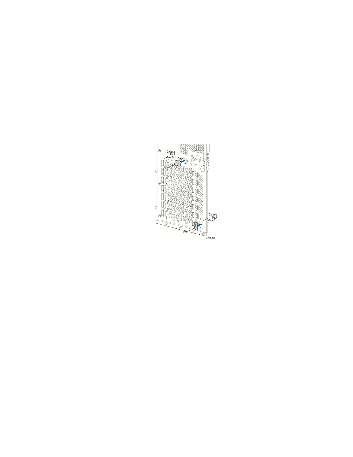
Hardware Installations and Upgrades
Intel® Remote Management Module 4
The Intel® Remote Management Module 4 plugs into a dedicated connector on the server board
and provides additional server management functionality to the server board.
This module provides a dedicated web server for viewing server information and remote control of
the system. It also provides Remote KVM Redirection and USB Media Redirection allowing USB
devices attached to the remote system to be used on the managed server.
Intel® Server Chassis P4000S family provide two Intel® Remote Management Module 4 knockout.
For instructions on installing the Intel® Remote Management Module 4, see Intel® Remote
Management Module 4 User Guide.
Figure 91. RMM4 knockout
Mechanical Locks
All configurations of the server chassis can support the installation of a padlock loop (see letter
A in the following figure) at the rear of the chassis.
Intel® Server Chassis P4000S Service Guide 63
Page 76

Hardware Installations and Upgrades
Figure 92. Mechanical Locks
64 Intel® Server Chassis P4000S Service Guide
Page 77

Technical Reference
Parameter
Min.
Max.
Peak
Unit
5V
0.3
10.0
A
12V1
0.7
16.0
18.0
A
12V2
1.5
16.0
18.0
A
3.3V
0.5
18.0
A
-12V
0.0
0.5 A
5V
0.0
2.5
3.0
A
3 Technical Reference
Power Supply Specification
The power supply specifications for your Intel® Server Chassis P4000S family depend upon the
configuration of chassis you purchased. Below power supply configurations are available:
365W fixed power supply
460W hot-swap power supply
550W fixed power supply
365-W Single Power Supply Input Voltage
100-127V at 50/60 Hz; 10A max.
200-240V at 50/60 Hz; 10A max.
365-W Single Power Supply Output Voltages
The following table defines the minimum power and current ratings. The power supply must meet
both static and dynamic voltage regulation requirements for all conditions.
Table 4. Power Supply Output Voltages
Notes:
1. Max combined power for all output shall not exceed 365W.
2. Peak combined power for all outputs shall not exceed 385W.
3. Max combined power of 12V1 and 12V2 shall not exceed 318W.
4. Max combined power on 3.3V and 5V shall not exceed 80W.
5. Peak power and current loading shall be supported for a minimum of 12 second.
460-W Hot-swap Power Supply Input Voltage
100-127V at 50/60 Hz; 10A max.
200-240V at 50/60 Hz; 10A max.
Intel® Server Chassis P4000S Service Guide 65
Page 78

Technical Reference
Parameter
Tolerance
Min.
Nom.
Max.
Unit
+12V
- 5%/+5%
+11.40
+12.00
+12.60
V
rms
+12V stby
- 5%/+5%
+11.40
+12.00
+12.60
V
rms
Parameter
Min.
Max.
Peak
Unit
3.3V
0.5
18.0
A
5V
0.3
15.0
A
12V1
0.7
24.0
28.0
A
12V2
0.7
24.0
28.0
A
12V3
1.5
18.0
A 12V
0.0
0.5 A
5Vstby
0.0
3.0
3.5
A
Parameter
Limits
Operating temperature
+10°C to +35°C with the maximum rate of change not to exceed 10°C per hour.
460-W Hot-swap Power Supply Output Voltages
The following table defines the minimum power and current ratings. The power supply must meet
both static and dynamic voltage regulation requirements for all conditions.
Table 5. Power Supply Output Voltages
550-W Single Power Supply Input Voltage
100-127V at 50/60 Hz; 10A max.
200-240V at 50/60 Hz; 10A max.
550-W Single Power Supply Output Voltages
The following table defines the minimum power and current ratings. The power supply must meet
both static and dynamic voltage regulation requirements for all conditions.
Table 6. Power Supply Output Voltages
Notes:
1. Max combined power for all output shall not exceed 550W.
2. Peak combined power for all outputs shall not exceed 630W for 20 seconds.
3. Max combined power of 12V1, 12V2 and 12V3 shall not exceed 530W.
4. Max combined power on 3.3V and 5V shall not exceed 120W.
System Environmental Requirements
Table 7. Environmental Requirements
66 Intel® Server Chassis P4000S Service Guide
Page 79

Parameter
Limits
Non-operating temperature
-40°C to +70°C
Non-operating humidity
50% to 90%, non-condensing with a maximum wet bulb of 28° C (at
temperatures from 25° C to 35° C)
Acoustic noise
7.0 BA LWA in a typical office ambient temperature (18-25°C)
Shock Operating
Half sine, 2 g, 11 milliseconds
Shock Unpackaged
Trapezoidal, 25 g, velocity change 136 inches/second (40 lbs to < 80 lbs)
Shock Packaged
Operational after a free fall of 9 – 36 inches depending on the weight
Vibration unpackaged
5 Hz to 500 Hz 2.20 g RMS random
Vibration packaged
5 Hz to 500 Hz 1.09 g RMS random
Packaged shock
Operational after a free fall of 9 – 36-inches depending on the weight
ESD
Air discharge: 0 to 15.0kV; Contact Discharge: 0 to 8.0kV
Current Usage
Current (maximum) at voltage level
Device
+3.3V
+ 5V
-5 V
+12 V
-12 V
5V Standby
Baseboard, Front Panel
Board and Fans
Processor(s)
Memory
3.5-inch Diskette Drive
CD-ROM Drive
Second 5.25-inch Device
Third 5.25-inch Device
1st Hard Drive
2nd Hard Drive
3rd Hard Drive
Technical Reference
Calculation Power Usage
The total combined wattage for your configuration must be less than the wattage rating for your
power supply. Use the two worksheets in this section to calculate the total used by your
configuration. For current and voltage requirements of add-in boards and peripherals, see your vendor
documents.
Worksheet, Calculating DC Power Usage
Table 8. Power Usage Worksheet
Intel® Server Chassis P4000S Service Guide 67
Page 80

Technical Reference
Current (maximum) at voltage level
4th Hard Drive
Expansion Board 1
Expansion Board 2
Expansion Board 3
Expansion Board 4
Expansion Board 5
Expansion Board 6
Intel® Remote Management
Module
Control Panel
Total Current
Voltage level and total current
(V X A = W)
Total watts for each voltage level
(+3.3 V) X (______ A)
________ W
(+5 V) X (______ A)
________ W
(+12 V) X (______ A)
________W
(–12 V) X (______ A)
________ W
(5 V standby) X (______ A)
________ W
Total Combined Wattage
________ W
Worksheet, Total Combined Power Used by the Server
From the previous worksheet, enter the total current for each column.
Multiply the voltage by the total current to get the total wattage for each voltage level.
Add the total wattage for each voltage level to arrive at the total combined power usage for the power
subsystem.
Table 9. Power Usage Worksheet 2
68 Intel® Server Chassis P4000S Service Guide
Page 81

Appendix A: Regulatory and Compliance Information
Appendix A: Regulatory and Compliance
Information
Please refer to the Server Products Regulatory and Safety document for the product regulatory
compliance reference. The document can be downloaded from
http://www.intel.com/support/motherboards/server/.
Intel® Server Chassis P4000S Service Guide 69
Page 82

Appendix B: Safety Information
Appendix B: Safety Information
Please refer to the Server Products Regulatory and Safety document for the Safety Information. The
document can be downloaded from http://www.intel.com/support/motherboards/server/.
70 Intel® Server Chassis P4000S Service Guide
Page 83

Appendix C: Installation/Assembly Safety Instructions
Appendix C: Installation/Assembly Safety
Instructions
Please refer to the Server Products Regulatory and Safety document for the Installation/Assembly
Safety Instructions. The document can be downloaded from
http://www.intel.com/support/motherboards/server/.
Intel® Server Chassis P4000S Service Guide 71
Page 84

Appendix D: Getting Help
Appendix D: Getting Help
If you encounter an issue with your server platform, please follow these steps to obtain
support on your product.
1. Get connected to our support web page for 24x7 support when you need it to get the
latest and most complete technical support information on all Intel Enterprise Server
and Storage Platforms. Information available at the support site includes:
Latest BIOS, firmware, drivers and utilities
Product documentation, installation and Quick Start Guides
Full product specifications, technical advisories and errata
Compatibility documentation for memory, hardware add-in cards, chassis
support matrix, and operating systems
Server and chassis accessory parts list for ordering upgrades or spare parts
A searchable knowledgebase to search for product information throughout the
support site
2. Send an email to Intel’s technical support center using the following online form if you
still cannot obtain a solution to your issue.
3. Lastly, you can contact an Intel support representative using one of the following
support phone numbers. Charges may apply. Intel customer support suggests filling
out the issue report form to better service the issue.
Intel now offers Channel Program members around-the-clock 24x7 technical phone
support+ on Intel® server boards, server chassis, server RAID controller cards, and
Intel® Server Management.
NOTE
You must login in to the reseller site to obtain the 24x7 number.
Warranty Information
To obtain warranty information, visit the following Intel web site:
http://www.intel.com/support/motherboards/server/sb/cs-010807.htm.
72 Intel® Server Chassis P4000S Service Guide
Page 85

Appendix E: Intel® Server Issue Report Form
Appendix E: Intel® Server Issue Report Form
Issue Report Form (Rev 3.5)
NOTE
FILLING OUT THIS FORM COMPLETELY IS REQUIRED FOR ANY ESCALATION
Customer Contact Information:
Customer Support Case#:
Intel® Server Board or System:
(Example: S1200BT, P4304XXSFCN)
Server Chassis:
(Example PXXXX. If third-party chassis used, indicate make and model.)
Base Board Information: (some information maybe found by accessing BIOS and
going through the Server Management menu -> System Information)
Baseboard PBA/TA/AA # (Example: 123456-789):
- You can find this on the white sticker label on the baseboard.
System BIOS Version:
Intel® Remote Management Module Firmware Version (if applicable):
Intel® Management Module BMC Revision (if applicable):
BMC/mBMC Version:
FRU/SDR Version:
HSC Version:
Has the latest BIOS been tried? (Yes/No):
Has the latest BMC/mBMC been tried? (Yes/No):
Has the latest IMM BMC been tried? (Yes/No):
Has the latest RMM Firmware been tried? (Yes/No):
Intel® Server Chassis P4000S Service Guide 73
Page 86

Appendix E: Intel® Server Issue Report Form
Type
Speed
sSpec
Thermal Solution
Processor 1
Processor 2
Processor 3
Processor 4
Manufacturer
Part Number
DRAM Part Number
On Intel tested list?
Type
Slot
Manufacturer
Model
Firmware
Has the latest FRU/SDR been tried? (Yes/No):
Has the latest HSC been tried? (Yes/No):
Processor information:
Thermal solution (Heat sink) examples:
(1U, Passive w/air ducting, Active w/fan, and so on)
Memory:
Add-in adapters (Example: NICs, Management Adapters, Serial Expansion Cards, PCIExpress* Adapters, RAID Controllers, SCSI Controllers, and so on):
Other third part hardware (Example: Example: KVM, Chassis, and so on):
74 Intel® Server Chassis P4000S Service Guide
Page 87

Appendix E: Intel® Server Issue Report Form
Description/Use
Manufacturer
Model
Firmware
Manufacturer
Model
Type
Size
Firmware
In Hot Swap Bay?
Storage Devices (Example: SCSI, SATA, SAS, USB, Tape, and so on):
Operating System Information (Example: RedHat* Enterprise Linux, Microsoft Windows
Server 2003*, Service pack 1, OEM CD):
Manufacturer:
Version:
Language version (English, Arabic, Chinese (Simplified)):
Service Pack Level or Kernel Revision:
Distribution (OEM/Retail):
Intel® RAID Controller: (Example SRCU42E)
RAID controller part number (PBA number):
RAID controller firmware version:
Has the latest RAID firmware been tried? (Yes/No):
RAID driver version:
Has the latest RAID driver been tried? (Yes/No):
RAID volumes configuration (disks and RAID level):
RAID volume use (Boot device/Data Volume):
Is BBU (Battery Backup Unit) installed? (Yes/No):
BBU part number:
Intel® Server Chassis P4000S Service Guide 75
Page 88

Appendix E: Intel® Server Issue Report Form
Detailed description of issue:
Troubleshooting tried:
Steps to replicate the issue:
76 Intel® Server Chassis P4000S Service Guide
Page 89

Appendix E: Intel® Server Issue Report Form
Issue impact statements:
Do you have any potential Intel system, or component purchases that this issue is
holding up? If yes, please provide a brief description below.
Do you have systems already purchased that are not being delivered to your customers
because of this issue? If yes, please provide a brief description below.
Have you returned systems or components to your place of purchase because of this
issue? If yes, please provide a brief description below.
*All other brands and names are property of their respective owners.
Intel® Server Chassis P4000S Service Guide 77
Page 90

Appendix F: Warranty
Appendix F: Warranty
Limited Warranty for Intel® Chassis Subassembly
Products
Intel warrants that the Products (defined herein as the Intel® chassis subassembly and all of its various
components and software delivered with or as part of the Products) to be delivered hereunder, if properly
used and installed, will be free from defects in material and workmanship and will substantially conform
to Intel's publicly available specifications for a period of three (3) years after the date the Product was
purchased from an Intel authorized distributor. Software of any kind delivered with or as part of products
is expressly provided "as is" unless specifically provided for otherwise in any software license
accompanying the software.
If any Product furnished by Intel which is the subject of this Limited Warranty fails during the warranty
period for reasons covered by this Limited Warranty, Intel, at its option, will:
REPAIR the Product by means of hardware and/or software; OR
REPLACE the Product with another Product; OR
REFUND the then-current value of the Product if Intel is unable to repair or replace the Product.
If such Product is defective, transportation charges for the return of Product to buyer within the USA will
be paid by Intel. For all other locations, the warranty excludes all costs of shipping, customs clearance,
and other related charges. Intel will have reasonable time to make repairs or to replace Product or to
refund the then-current value of the Product.
In no event will Intel be liable for any other costs associated with the replacement or repair of Product,
including labor, installation or other costs incurred by buyer and in particular, any costs relating to the
removal or replacement of any product soldered or otherwise permanently affixed to any printed circuit
board.
This Limited Warranty, and any implied warranties that may exist under state law, apply only to the
original purchaser of the Product.
Extent of Limited Warranty
Intel does not warrant that Products to be delivered hereunder, whether delivered standalone or integrated
with other Products, including without limitation semiconductor components, will be free from design
defects or errors known as "errata." Current characterized errata are available upon request.
This Limited Warranty does not cover damages due to external causes, including accident, problems with
electrical power, usage not in accordance with product instructions, misuse, neglect, alteration, repair,
improper installation, or improper testing.
78 Intel® Server Chassis P4000S Service Guide
Page 91

Appendix F: Warranty
Warranty Limitations and Exclusions
These warranties replace all other warranties, expressed or implied including, but not limited to, the
implied warranties of merchantability and fitness for a particular purpose. Intel makes no expressed
warranties beyond those stated here. Intel disclaims all other warranties, expressed or implied including,
without limitation, implied warranties of merchantability and fitness for a particular purpose. Some
jurisdictions do not allow the exclusion of implied warranties, so this limitation may not apply.
All expressed and implied warranties are limited in duration to the limited warranty period. No warranties
apply after that period. Some jurisdictions do not allow limitations on how long an implied warranty lasts,
so this limitation may not apply to you.
Limitations of Liability
Intel's responsibility under this, or any other warranty, implied or expressed, is limited to repair,
replacement, or refund, as set forth above. These remedies are the sole and exclusive remedies for any
breach of warranty. Intel is not responsible for direct, special, incidental, or consequential damages
resulting from any breach of warranty under another legal theory including, but not limited to, lost profits,
downtime, goodwill, damage to or replacement of equipment and property, and any costs of recovering,
reprogramming, or reproducing any program or data stored in or used with a system containing this
product. Some jurisdictions do not allow the exclusion or limitation of incidental or consequential
damages, so the above limitations or exclusions may not apply to you.
This limited warranty gives you specific legal rights, and you may also have other rights that vary from
jurisdiction to jurisdiction.
Any and all disputes arising under or related to this Limited Warranty shall be adjudicated in the
following forums and governed by the following laws: for the United States of America, Canada, North
America, and South America, the forum shall be Santa Clara, California, USA, and the applicable law
shall be that of the State of California, USA; for the Asia Pacific region, the forum shall be Singapore and
the applicable law shall be that of Singapore; for Europe and the rest of the world, the forum shall be
London and the applicable law shall be that of the United Kingdom. In the event of any conflict between
the English language version and any other translated version(s) of this Limited Warranty, the English
language version shall control.
How to Obtain Warranty Service
To obtain warranty service for this Product, you may contact Intel or your authorized distributor.
North America and Latin America: To obtain warranty repair for the product, please go to the following Web
site to obtain instructions: http://support.intel.com/support/motherboards/draform.htm
In Europe and in Asia: Contact your original authorized distributor for warranty service.
Any replacement Product is warranted under this written warranty and is subject to the same limitations
and exclusions for the remainder of the original warranty period.
Telephone Support
If you cannot find the information you need on Intel's World Wide Web site (http://www.intel.com), call
your local distributor or an Intel Customer Support representative.
Intel® Server Chassis P4000S Service Guide 79
Page 92

Appendix F: Warranty
See Appendix D: Getting Help for telephone numbers.
Returning a Defective Product
Before returning any product, call your authorized dealer/distribution authority.
80 Intel® Server Chassis P4000S Service Guide
 Loading...