

Page 1

Intel® NetStructure
™
Intel
®
NetStructure
™
480T Routing Switch User Guide
480T Routing Switch
User GuideUser Guide
User Guide
User GuideUser Guide
Page 2

Copyright © 2001, Intel Corporation. All rights reserved.
Intel Corporation, 5200 NE Elam Young Parkway, Hillsboro OR 97124-6497
Intel Corporation assumes no responsibility for errors or omissions in this manual. Nor does Intel make any commitment to
update the information contained herein.
* Other names and brands may be claimed as the property of others.
FourthEdition November 2001 A14542-001
Page 3

Contents
Contents ................................................ i
Preface .................................................1
Introduction ..................................................................... 1
Related Publications .......................................................2
1: Overview .......................................... 3
Summary of Features ..................................................... 3
Full-Duplex Support..................................................... 5
Virtual LANs (VLANs) .................................................. 5
Spanning Tree Protocol (STP) .................................... 5
Quality of Service (QoS).............................................. 6
Unicast Routing ........................................................... 6
IP Multicast Routing .................................................... 6
Load Sharing............................................................... 7
Software Licensing - Router License Keys .................. 7
Basic Functionality ...................................................... 7
Full Layer 3 Functionality ............................................ 8
Verifying the Router License ....................................... 8
Upgrading a Router License........................................ 8
Physical Features ............................................................ 8
Front View ................................................................... 8
Rear View .................................................................... 9
Page 4

C O N T E N T S
AC Connector ............................................................ 10
Serial Number............................................................ 10
Console Port.............................................................. 10
Management Port ...................................................... 10
MAC Address ............................................................ 10
Switch LEDs .............................................................. 10
Software Factory Defaults ............................................12
Media Types, Distances and Specifications ...............14
Optical Output Power ................................................ 15
2: Installation and Setup ................... 17
Important Safety Information .......................................17
Determining the Switch Location ................................18
Installing the Switch ...................................................... 18
Rack Mounting........................................................... 18
Free-Standing............................................................ 20
Connecting Equipment to the Console Port .............. 20
Turning On the Switch .............................................. 20
Checking the Installation ........................................... 20
Logging In for the First Time ........................................21
Upgrading Your Firmware ............................................22
Installing the Gigabit Interface Connector (GBIC) ......22
3: Using Intel® Device View .............. 23
Installing Intel Device View ..........................................23
To Install Intel Device View ....................................... 24
Starting the Windows§ Version ................................. 25
Starting the Web Version........................................... 25
Installing a New Device ................................................. 26
To Install and Configure a New Switch for Management
26
Using the Device Tree ...................................................26
Device Tree icons...................................................... 27
To Add a Device to the Device Tree.......................... 28
To Refresh the Device Tree ...................................... 28
To Delete a Device from the Device Tree ................. 28
To Find a Device in the Device Tree ......................... 28
Losing Contact with a Device .................................... 29
Managing a Switch ........................................................29
ii
Page 5

Intel® NetStructure™ 480T Routing Switch User Guide
Viewing RMON Information ..........................................30
To View RMON Statistics .......................................... 31
4: Using Web Device Manager .......... 33
Enabling and Disabling Web Access ...........................33
Setting Up Your Browser ..............................................34
Accessing Web Device Manager ..................................35
Navigating Web Device Manager .................................35
Task Frame ............................................................... 35
Content Frame........................................................... 36
Browser Controls .......................................................36
Status Messages .......................................................37
Stand-alone Buttons ..................................................37
Saving Changes .............................................................37
Filtering Information ......................................................38
Using the
Get Command to Configure a VLAN ............38
TFTP Server ...................................................................38
5: Accessing the Switch .................... 39
Understanding the Command Syntax .........................39
Syntax Helper ............................................................ 40
Command Completion with Syntax Helper................ 40
Abbreviated Syntax ................................................... 40
Command Shortcuts.................................................. 41
Numerical Ranges ..................................................... 41
Names ....................................................................... 41
Symbols ..................................................................... 42
Line-Editing Keys ..........................................................43
Command History .......................................................... 44
Common Commands ....................................................44
Configuring Management Access ................................48
User Account ............................................................. 48
Administrator Account ............................................... 48
Prompt Text ............................................................... 49
Default Accounts ....................................................... 49
Changing the Default Password ................................49
Creating a Management Account .............................. 50
Viewing Accounts ......................................................50
Deleting an Account ..................................................51
iii
Page 6

C O N T E N T S
Domain Name Service Client ........................................51
Real-time Basic Connectivity Checking ......................52
Ping ........................................................................... 52
Traceroute ................................................................. 53
Methods of Managing the Switch ................................53
Using the Console Interface ...................................... 54
Using the 10/100 UTP Management Port.................. 54
Using Telnet ...................................................................54
Connecting to Another Host Using Telnet ................. 55
Configuring Switch IP Parameters............................. 55
Using a BOOTP Server .............................................55
Manually Configuring the IP Settings ........................56
Disconnecting a Telnet Session ................................ 58
Controlling Telnet Access .......................................... 58
Using Access Profiles ...................................................59
Creating an Access Profile ........................................ 59
Access Profile Rules.................................................. 61
Access Profile Example ............................................. 61
Using Web Device Manager .........................................61
Controlling Web Access ............................................ 62
Simple Network Management Protocol (SNMP) .........62
Accessing Switch Agents .......................................... 63
Supported MIBs......................................................... 63
Configuring SNMP Settings ....................................... 63
Displaying SNMP Settings......................................... 66
Authenticating Users ....................................................66
RADIUS Client........................................................... 66
Per-Command Authentication Using RADIUS ...........67
Configuring RADIUS Client .......................................67
RADIUS RFC 2138 Attributes ...................................70
Configuring TACACS+ .............................................. 70
Simple Network Time Protocol (SNTP) .......................72
Configuring and Using SNTP .................................... 73
SNTP Configuration Commands ............................... 77
SNTP Example .......................................................... 77
iv
Page 7

Intel® NetStructure™ 480T Routing Switch User Guide
6: Configuring Ports .......................... 79
Configuring Ports ..........................................................79
Changing Port Speed and Duplex Setting................. 80
Random Early Detection (RED)................................. 80
Turning Off Auto-negotiation for a GBIC Port............ 81
Jumbo Frames ...............................................................81
Enabling Jumbo Frames............................................ 82
Path MTU Discovery.................................................. 82
IP Fragmentation with Jumbo frames ........................ 83
IP Fragmentation within a VLAN ...............................83
Load Sharing ..................................................................84
Load Sharing Algorithms ........................................... 84
Configuring Load Sharing.......................................... 85
Load-Sharing Example .............................................. 86
Verifying the Load Sharing Configuration.................. 86
Port Commands .............................................................86
Port-Mirroring ................................................................90
Mirroring Combined with Load Sharing ..................... 90
Mirroring IP Multicast Traffic ...................................... 91
Mirroring Bandwidth................................................... 91
Mirroring and Flooding............................................... 91
Mirroring and Download Configuration ...................... 91
Port-Mirroring Commands ............................................91
Port-Mirroring Example.............................................. 92
Enterprise Discovery Protocol .....................................92
EDP Commands........................................................ 93
7: Virtual LANs (VLANs) ..................... 95
Overview of Virtual LANs ..............................................95
Benefits...................................................................... 95
VLANs Help to Control Traffic ...................................96
VLANs Provide Extra Security ...................................96
VLANs Ease Device Change and Movement ............96
Bi-directional Rate Shaping for Layer 3 Routed VLANs .
96
Types of VLANs .............................................................97
Port-Based VLANs .................................................... 97
Spanning Switches with Port-Based VLANs .............98
Tagged VLANs .......................................................... 99
Uses of Tagged VLANs ...........................................100
v
Page 8

C O N T E N T S
Assigning a VLAN Tag ............................................100
Mixing Port-Based and Tagged VLANs ...................102
Protocol-Based VLANs ............................................ 102
Predefined Protocol Filters ......................................103
Defining Protocol Filters ..........................................104
Deleting a Protocol Filter .........................................105
Precedence of Tagged Packets Over Protocol Filters....
105
VLAN Names ................................................................105
Default VLAN........................................................... 106
Renaming a VLAN................................................... 106
Configuring VLANs on the Switch .............................106
VLAN Configuration Examples ................................ 108
Example 1 ................................................................108
Example 2 ................................................................109
Example 3 ................................................................109
Example 4 ................................................................109
Example 5 ................................................................109
Displaying VLAN Settings ..........................................110
VLAN Statistics ............................................................ 111
Deleting VLANs ........................................................... 111
VLAN Tunneling (vMANs) ...........................................111
MAC-Based VLANs .....................................................114
MAC-Based VLAN Guidelines................................. 114
MAC-Based VLAN Limitations................................. 115
MAC-Based VLAN Commands ............................... 116
MAC-Based VLAN Example.................................... 116
Timed Configuration Download, MAC-Based VLANs ....
117
Example ................................................................... 118
8: Forwarding Database (FDB) ......... 119
Overview of the FDB ...................................................119
IP FDB Performance ............................................... 119
FDB Contents .......................................................... 120
FDB Entry Types ..................................................... 120
Dynamic Entries ......................................................120
Non-aging Entries ....................................................120
Permanent Entries ...................................................121
Blackhole Entries ..................................................... 121
vi
Page 9

Intel® NetStructure™ 480T Routing Switch User Guide
How FDB Entries Get Added................................... 121
Associating a QoS Profile with an FDB Entry.......... 122
Configuring FDB Entries .............................................122
FDB Configuration Examples 123
Displaying FDB Entries ...............................................124
Removing FDB Entries ................................................124
9: Spanning Tree Protocol (STP) ..... 125
Overview of Spanning Tree Protocol .........................125
Spanning Tree Domains .............................................125
STP Configurations .....................................................126
Configuring STP ...................................................... 129
STP Configuration Example .................................... 132
Displaying STP Settings .............................................132
Disabling and Resetting STP ......................................133
10: Quality of Service (QoS) ............ 135
Overview of Policy-Based Quality of Service ...........135
Random Early Detection.......................................... 136
Policy-Based Routing and Route Load Sharing ...... 136
Performance Impact ....................................................136
Applications and Types of QoS .................................137
Voice Applications ................................................... 137
Video Applications ................................................... 137
Critical Database Applications................................. 138
Web Browsing Applications ..................................... 138
File Server Applications ........................................... 139
Building Blocks ...........................................................139
Assigning QoS Attributes ..........................................139
QoS Profiles .................................................................140
Configuring a QoS Profile ........................................ 142
Modifying a QoS Profile ........................................... 144
Traffic Groupings and Creating a QoS Policy ..........144
IP-Based Traffic Groupings ..................................... 145
MAC-Based Traffic Groupings................................. 145
Permanent MAC Addresses ....................................146
Dynamic MAC Addresses ........................................146
Blackhole MAC Address .......................................... 146
Broadcast/Unknown Rate Limiting MAC Address ...147
Verifying MAC-Based QoS Settings ........................147
vii
Page 10

C O N T E N T S
Explicit Class of Service Traffic Groupings (802.1p and
DiffServ)................................................................... 147
Configuring 802.1p Priority ......................................148
Observing 802.1p Information .................................148
Replacing 802.1p Priority Information .....................149
802.1p Commands ..................................................150
Configuring DiffServ ................................................ 151
Observing DiffServ Information ...............................152
Changing DiffServ Code Point Assignments in the QoS
Profile ...................................................................... 152
Replacing DiffServ Code Points ..............................153
DiffServ Example .....................................................156
Physical and Logical Groupings .............................. 156
Source Port ..............................................................156
VLAN ....................................................................... 157
Verifying Physical and Logical Groupings ...............157
Verifying Configuration and Performance ................157
QoS Monitor ............................................................ 158
Real-Time Performance Monitoring ......................... 158
Background Performance Monitoring ...................... 159
Displaying QoS Information..................................... 159
Modifying a QoS Policy ..............................................160
QoS Profile Buffer .......................................................160
Maximum QoS Buffer .............................................. 160
Bandwidth Settings and Their Impact...................... 161
Maximum bandwidth settings ..................................161
Minimum bandwidth settings ...................................162
Bi-directional Rate Shaping for Layer 3 Routed VLANs
163
Configuring Bi-Directional Rate Shaping ................. 164
Bi-Directional Rate Shaping Limitations .................. 165
Bi-Directional Rate Shaping Commands ................. 165
11: Enterprise Standby Router Protocol
(ESRP) .............................................. 167
Overview ......................................................................167
ESRP-Aware Switches............................................ 168
ESRP Basics ................................................................168
Multiple ESRP VLANs ............................................. 169
Mixing Clients and Routers on ESRP VLANs.......... 169
viii
Page 11

Intel® NetStructure™ 480T Routing Switch User Guide
Ensure that EDP is Enabled .................................... 169
ESRP and Host Attached Ports............................... 169
Open Shortest Path First and ESRP ....................... 169
Determining the ESRP Master ....................................170
ESRP Tracking ........................................................ 171
ESRP VLAN Tracking ..............................................171
ESRP Route Table Tracking ...................................171
ESRP Ping Tracking ................................................171
ESRP Election Algorithms ....................................... 172
Master Switch Behavior........................................... 172
Standby Switch Behavior......................................... 172
Electing the Master Switch ...................................... 173
Failover Time ........................................................... 173
ESRP Options ..............................................................174
ESRP Host Attach ................................................... 174
ESRP Domains........................................................ 175
ESRP Groups .......................................................... 175
Linking ESRP Switches ..............................................177
Configuring ESRP and Multinetting ...........................177
ESRP and Spanning Tree ...........................................177
ESRP and VLAN Aggregation ....................................178
ESRP Commands ........................................................179
ESRP Examples ...................................................... 182
Single VLAN Using Layer 2 and Layer 3 Redundancy ..
182
Multiple VLANs Using Layer 2 Redundancy ............184
Displaying ESRP Information .....................................186
ESRP Environment and Diagnostic Tracking .......... 186
12: IP Unicast Routing .................... 189
Overview of IP Unicast Routing .................................189
Policy-Based Routing and Route Load-Sharing ...... 190
Router Interfaces ..................................................... 191
Populating the Routing Table .................................. 192
Dynamic Routes ...................................................... 192
Static Routes ...........................................................192
Multiple Routes ........................................................193
IP Route Sharing ..................................................... 193
Route Map Support .....................................................193
Route Map Support for OSPF Export ...................... 194
ix
Page 12

C O N T E N T S
BGP and OSPF Route Map Support for Tagging.... 195
BGP and OSPF Route Map Support for DSB Accounting
195
Proxy ARP ....................................................................196
ARP-Incapable Devices........................................... 196
Proxy ARP Between Subnets.................................. 196
Relative Route Priorities .............................................197
IP Multinetting ..............................................................198
IP Multinetting Operation ......................................... 199
IP Multinetting Examples ......................................... 200
Configuring IP Unicast Routing .................................201
Verifying the IP Unicast Routing Configuration ....... 202
VLAN Aggregation ......................................................202
VLAN Aggregation Properties ................................. 204
VLAN Aggregation Limitations................................. 204
SubVLAN Address Range Checking ....................... 205
Isolation Option for Communication Between subVLANs
205
VLAN Aggregation Commands ............................... 205
VLAN Aggregation Example.................................... 206
Verifying the VLAN Aggregation Configuration ....... 207
Configuring DHCP/BOOTP Relay ..............................207
Verifying the DHCP/BOOTP Relay Configuration ... 208
UDP Forwarding ..........................................................208
Configuring UDP Forwarding................................... 209
UDP-Forwarding Example....................................... 209
ICMP Packet Processing ......................................... 209
UDP-Forwarding Commands .................................. 210
IP Commands ..............................................................211
Routing Configuration Example ................................219
Displaying Router Settings ........................................220
Resetting and Disabling Router Settings ..................221
13: RIP and OSPF ............................ 223
Overview ......................................................................223
Distinguishing RIP and OSPF ................................. 224
Overview of RIP ........................................................... 225
Routing Table .......................................................... 225
Split Horizon ............................................................ 225
Poison Reverse ....................................................... 225
x
Page 13

Intel® NetStructure™ 480T Routing Switch User Guide
Triggered Updates................................................... 226
Route Advertisement of VLANs ............................... 226
RIP Version 1 Compared to RIP Version 2 ............. 226
Overview of OSPF .......................................................226
Link-State Database ................................................ 227
Areas ....................................................................... 227
Area 0 ......................................................................228
Stub Areas ...............................................................228
Not-So-Stubby-Areas (NSSAs) ...............................228
Normal Area ............................................................229
Virtual Links .............................................................229
OSPF Database Overflow ....................................... 231
OSPF Passive Interface ..............................................231
Routing with OSPF ......................................................232
Set the RouterID ...................................................... 232
Route Redistribution ...................................................232
Configuring Route Redistribution............................. 233
Redistributing Routes into OSPF ............................. 233
Redistributing Routes into RIP ................................234
OSPF Timers and Authentication ..............................235
OSPF Password Encryption .......................................235
Route Map Support .....................................................235
Route Map Support for OSPF Export ...................... 236
BGP and OSPF Route Map Support for Tagging .... 236
BGP and OSPF Route Map Support for DSB Accounting
237
Configuring RIP ...........................................................237
RIP Configuration Example ........................................240
Displaying RIP Settings ..............................................242
Resetting and Disabling RIP .......................................242
Configuring OSPF .......................................................243
OSPF Configuration Example ................................. 249
Configuration for ABR1............................................ 250
Configuration for IR1 ............................................... 251
Displaying OSPF Settings ..........................................252
Resetting and Disabling OSPF Settings ....................253
xi
Page 14

C O N T E N T S
14: Border Gateway Protocol (BGP) 255
Overview ......................................................................255
BGP Attributes .............................................................256
BGP Communities ....................................................... 256
BGP Features ...............................................................257
Route Reflectors...................................................... 257
Route Confederations.............................................. 258
Route Confederation Example ................................258
Route Aggregation ......................................................262
Using Route Aggregation ........................................262
Route Map Support ................................................. 262
Interior Gateway Protocol (IGP) Synchronization.... 262
Using the Loopback Interface.................................. 263
OSPF-to-BGP Route Redistribution ........................ 263
BGP Peer Groups.................................................... 263
BGP MD5 Authentication ............................................265
BGP Password Encryption ......................................... 266
Configuring BGP .........................................................266
Displaying BGP Settings ............................................ 271
Resetting and Disabling BGP .....................................272
BGP Route Selection ..................................................273
15: IP Multicast Routing .................. 275
Overview ......................................................................275
DVMRP Overview.................................................... 276
PIM Overview .......................................................... 276
PIM-DM ................................................................... 276
PIM Sparse Mode (PIM-SM) ...................................277
Static Rendezvous Points (RPs) .............................277
PIM Mode Translation ............................................. 277
IP Multicast Cache Display...................................... 278
IGMP Overview ............................................................278
IGMP Snooping ....................................................... 278
IGMP Leave Message .............................................279
IGMP Display ...........................................................279
IGMP Query Interval ................................................280
IGMP Configuration Commands ................................280
Configuring IP Multicasting Routing .........................282
Configuration Examples .......................................... 285
Configuration for IR1 ............................................... 285
xii
Page 15

Intel® NetStructure™ 480T Routing Switch User Guide
PIM-SM Configuration Example .............................. 286
Configuration for ABR1............................................ 287
Displaying IP Multicast Routing Settings ..................287
Deleting and Resetting IP Multicast Settings ...........288
16: IPX Routing ............................... 291
Overview of IPX ...........................................................291
Router Interfaces ..................................................... 291
IPX Encapsulation Types ........................................ 293
IPX and IP .....................................................................293
IP and IPX on the Same VLAN................................ 294
Tagged IPX VLAN ................................................... 294
IPX Load Sharing .................................................... 294
Populating the Routing Table .................................. 295
Dynamic Routes ...................................................... 295
Static Routes ...........................................................295
IPX/RIP Routing ...........................................................295
GNS Support ........................................................... 296
Routing SAP Advertisements .................................. 296
Configuring IPX ...........................................................297
Verifying IPX Router Configuration.......................... 297
Protocol-Based VLANs for IPX ................................ 298
Tuning...................................................................... 298
Tagged VLANs and IPX .......................................... 299
IPX and Round-Robin Load Sharing ....................... 299
IPX Performance Testing Using Traffic Generators 299
IPX and Bi-Directional Rate Shaping....................... 299
IPX Commands ............................................................ 300
IPX Configuration Example ........................................304
Displaying IPX Settings ..............................................305
Resetting and Disabling IPX .......................................306
17: Access Policies ......................... 309
Overview of Access Policies ......................................309
IP Access Lists ........................................................ 309
Routing Access Policies .......................................... 310
§
IPX
Routing Access Policies .................................310
Route Maps ............................................................. 311
Using IP Access Lists .................................................311
How IP Access Lists Work....................................... 312
xiii
Page 16

C O N T E N T S
Precedence Numbers.............................................. 312
Specifying a Default Rule ........................................ 312
The Permit-Established Keyword ............................ 313
Adding and Deleting Access List Entries................. 314
Maximum Entries..................................................... 314
Access Lists for ICMP .................................................314
Security and Access Policies................................... 315
Verifying Access List Configurations ....................... 315
Access List Commands ..............................................315
IP Access List Examples ............................................320
Example 1: Using the Permit-Established Keyword 320
Step 1 – Deny IP Traffic ..........................................320
Step 2 – Allow TCP Traffic ......................................321
Step 3 - Permit-Established Access List ..................322
Example 2: Filtering ICMP Packets......................... 323
Using Routing Access Policies ..................................323
Creating an Access Profile ...................................... 324
Configuring an Access Profile Mode ....................... 324
Adding an Access Profile Entry ............................... 325
Specifying Subnet Masks ........................................325
Sequence Numbering ..............................................326
Permit and Deny Entries ..........................................326
Autonomous System Expressions ...........................326
Deleting an Access Profile Entry .............................327
Applying Access Profiles ......................................... 327
Routing Access Policies for RIP .............................. 327
Examples ................................................................. 328
Routing Access Policies for OSPF .......................... 329
OSPF Access Policy Example .................................330
Routing Access Policies for DVMRP ....................... 331
DVMRP Example ..................................................... 332
Routing Access Policies for PIM.............................. 332
PIM Example ...........................................................333
Routing Access Policies for BGP ............................ 333
Making Changes to a Routing Access Policy ...........334
Removing a Routing Access Policy ..........................334
Routing Access Policy Commands ...........................335
Using Route Maps .......................................................337
Creating a Route Map ............................................. 338
Add Entries to the Route Map ................................. 338
Add Statements to the Route Map Entries .............. 338
xiv
Page 17

Intel® NetStructure™ 480T Routing Switch User Guide
Route Map Operation .............................................. 341
Route Map Example ................................................341
Changes to Route Maps.......................................... 342
Route Maps in BGP................................................. 343
Route Map Commands............................................ 343
18: Server Load Balancing (SLB) ..... 347
Overview .......................................................................347
SLB Components ........................................................347
Nodes ...................................................................... 348
Pools........................................................................ 348
Virtual Servers ......................................................... 348
Forwarding Modes .......................................................349
Transparent Mode ................................................... 350
Translational Mode .................................................. 352
Port Translation Mode ............................................. 354
GoGo Mode ............................................................. 355
VIP Network Advertisement ........................................356
Balancing Methods ......................................................357
Round-Robin ........................................................... 357
Ratio ........................................................................ 358
Ratio Weight ............................................................358
Least Connections................................................... 358
Priority ..................................................................... 359
Basic SLB Commands ................................................359
Advanced SLB Application Example .........................363
Health Checking ..........................................................368
Health check definitions........................................... 368
Layer 3 Ping Check .................................................368
Layer 4 Port Check ..................................................368
Layer 7 HTTP Check ...............................................368
Layer 7 FTP Check ..................................................368
Layer 7 NNTP Check ...............................................369
Layer 7 POP3, SMTP, and Telnet Check ................369
Internal Health Checking ......................................... 369
Ping-Check ..............................................................370
TCP-Port-Check ......................................................370
Service-Check .........................................................371
GoGo Mode Health Checking ..................................372
SLB Global Connection Timeout .............................374
xv
Page 18

C O N T E N T S
External Health Checking ........................................ 374
Health Checks for Web Cache Redirection and Policy
Based Routing......................................................... 375
Layer 4 Flows .......................................................... 376
Policy-Based Routing with Route Load-Sharing...... 376
Layer 4 Destination Port .......................................... 376
Maintenance Mode ......................................................377
Persistence ..................................................................377
Client Persistence.................................................... 377
SLB Proxy Client Persistence .................................. 377
Sticky Persistence ................................................... 378
Server Load Balancing with ESRP ............................378
Configuring the Switches for SLB and ESRP .......... 380
Combined SLB and ESRP failover .......................... 381
Configuration of SLB with ESRP ............................. 382
Web-Server Configuration ....................................... 382
Using High Availability System Features ..................382
Redundant SLB ....................................................... 383
Using Ping-Check.................................................... 383
Configuring Active-Active Operation........................ 383
Sample Active-Active Configuration ........................384
Using Manual Fail-Back........................................... 387
Using SLB High Availability ..................................... 387
Configuring Clients .................................................. 388
Configuring Switches for SLB H/A ...........................388
Notes on Configuring SLB H/A ................................ 390
Web Server configuration ........................................ 391
Advanced SLB Commands ........................................392
Web Cache Redirection ..............................................398
Flow Redirection...................................................... 398
Precedence of Flow Redirection Rules ................... 399
Flow Redirection Commands .................................. 400
Flow Redirection Example....................................... 401
19: Status Monitoring and Statistics .....
403
Status Monitoring ........................................................403
Port Statistics ..............................................................405
Port Errors ...................................................................406
xvi
Page 19

Intel® NetStructure™ 480T Routing Switch User Guide
Port Monitoring Display Keys ....................................407
Setting the System Recovery Level......................... 408
Logging ........................................................................408
Local Logging .......................................................... 410
If not specified, info and higher priority messages dis-
play. ......................................................................... 410
Real-Time Display ................................................... 411
Remote Logging ...................................................... 411
Logging Configuration Changes.............................. 412
Logging Commands ................................................ 412
RMON ............................................................................414
RMON Features ...................................................... 415
Statistics ..................................................................415
History ..................................................................... 415
Alarms .....................................................................416
Events ......................................................................416
Configuring RMON .................................................. 416
RMON Probe with Security Features Enabled ........417
Event Actions........................................................... 417
20: Software Upgrade and Boot Options
419
Overview .......................................................................419
Saving Configuration Changes ..................................419
Upgrading Your Switch ...............................................420
Starting a TFTP Server............................................ 420
Upgrading the BootROM ......................................... 421
Upgrading the Firmware .......................................... 422
Downgrading Your Switch ....................................... 422
Using TFTP to Upload the Configuration ..................423
Using TFTP to Download the Configuration .............424
Downloading a Complete Configuration .................. 424
Downloading an Incremental Configuration............. 425
Scheduled Incremental Configuration Download .... 425
Remember to Save ......................................................426
Accessing BootROM ...................................................426
Boot Option Commands .............................................427
xvii
Page 20

Intel® NetStructure™ 480T Routing Switch User Guide
A: Technical Specifications and
Supported Limits............................... 431
Technical Specifications .............................................431
Supported Standards, RFCs and Protocols ..............433
Supported Limits .........................................................434
B: Troubleshooting............................ 439
LEDs .............................................................................439
Using the Command-Line Interface ...........................440
Port Configuration .......................................................442
OSPF (Open Shortest Path First) ...............................443
VLANs ...........................................................................444
VLAN Names ...........................................................445
VLANs, IP Addresses and Default Routes ..............445
STP ................................................................................445
ESRP .............................................................................446
Troubleshooting Tools ................................................446
Debug Tracing ......................................................... 446
TOP Command ........................................................ 446
C: Regulatory Information................. 447
Compliance statements ..............................................447
Warnings ......................................................................449
Limited Hardware Warranty ........................................450
D: Intel Customer Support ................ 461
Index ................................................ 465
xviii
Page 21

Intel
®
NetStructure
™
480T Routing Switch User Guide
List of Figures
Figure 1.1: Intel® NetStructure™ 480T routing switch
(front) ........................................................................... 9
Figure 1.2: Intel
and without redundant power supply) ......................... 9
Figure 2.1: Fitting the mounting bracket ........................ 19
Figure 2.2: GBIC module (1000 Mbps ports) ................. 22
Figure 7.1: Example of a port-based VLAN on the Intel
NetStructure™ 480T routing switch .......................... 97
Figure 7.2: Single port-based VLAN spanning two switches
98
Figure 7.3: Two port-based VLANs spanning two switches
99
Figure 7.4: Physical diagram of tagged and untagged traffic
101
Figure 7.5: Logical diagram of tagged and untagged traffic
101
Figure 7.6: Protocol-based VLANs .............................. 103
Figure 7.7: vMAN Configuration ................................. 113
Figure 9.1: Multiple Spanning Tree Domains - VLAN tag-
ging for trunk connections ....................................... 127
Figure 9.2: Tag-based STP configuration -Incorrect .... 128
Figure 10.1: Ethernet packet encapsulation .................. 148
Figure 10.2: IP packet header encapsulation ................ 151
Figure 11.1: ESRP host attach ...................................... 175
Figure 11.2: ESRP groups ............................................ 176
Figure 11.3: ESRP example using Layer 2 and Layer 3 re-
dundancy .................................................................. 183
Figure 11.4: ESRP example using Layer 2 redundancy 184
Figure 12.1: Routing between VLANs ......................... 191
Figure 12.2: VLAN aggregation ................................... 203
Figure 12.3: Unicast routing configuration example .... 219
Figure 13.1: Virtual link for stub area .......................... 230
Figure 13.2: Virtual link providing redundancy ........... 230
Figure 13.3: Route redistribution .................................. 233
Figure 13.4: RIP configuration example ....................... 241
Figure 13.5: OSPF configuration example ................... 249
®
NetStructure™ 480T routing switch (with
®
xix
Page 22

C O N T E N T S
Figure 14.1: Route reflectors ........................................ 257
Figure 14.2: Routing confederation .............................. 258
Figure 15.1: IP multicast routing PIM-DM configuration ex-
ample ........................................................................ 285
Figure 15.2: IP multicast routing using PIM-SM configura-
tion ........................................................................... 286
Figure 16.1: IPX VLAN configuration ......................... 292
Figure 16.2: IPX routing configuration example .......... 304
Figure 17.1: Access list denies all TCP and UDP traffic ....
321
Figure 17.2: Access list allows TCP traffic .................. 321
Figure 17.3: Host A initiates a TCP session to Host B . 322
Figure 17.4: Permit-established access list filters out SYN
packet to destination ................................................ 323
Figure 17.5: ICMP packets are filtered out ................... 323
Figure 17.6: RIP access policy example ....................... 328
Figure 17.7: OSPF access policy example .................... 331
Figure 17.8: Route maps ............................................... 341
Figure 18.1: Transparent mode ..................................... 351
Figure 18.2: Translational mode ................................... 353
Figure 18.3: GoGo mode .............................................. 355
Figure 18.4: Advanced SLB configuration ................... 364
Figure 18.5: SLB using ESRP and dual-attached servers ...
379
Figure 18.6: Active-active configuration ...................... 385
Figure 18.7: SLB failover configuration using SLB H/A ...
388
Figure 18.8: Flow-redirection example ........................ 401
xx
Page 23

Intel
®
NetStructure
™
480T Routing Switch User Guide
List of Tables
Table 1.1: Switch LEDs .................................................. 11
Table 1.2: Global Factory Defaults ................................. 12
Table 1.3: Media Types and Distances ........................... 14
Table 1.4: 1000LH Specifications .................................. 15
Table 4.1: Multi-Select List Box Key Definitions .......... 36
Table 5.1: Command Syntax Symbols ........................... 42
Table 5.2: Line-Editing Keys .......................................... 43
Table 5.3: Common Commands ..................................... 44
Table 5.4: Default Accounts ........................................... 49
Table 5.5: DNS Commands ............................................ 51
Table 5.6: Ping Command Parameters ........................... 52
Table 5.7: Access Profile Configuration Commands ..... 59
Table 5.8: SNMP Configuration Commands .................. 64
Table 5.9: RADIUS® Commands ................................... 68
Table 5.10: TACACS+ Commands ................................ 71
Table 5.11: Greenwich Mean Time Offsets .................... 74
Table 5.12: SNTP Configuration Commands ................. 77
Table 6.1: Port Commands ............................................. 87
Table 6.2: Port-Mirroring Configuration Commands ..... 91
Table 6.3: EDP Commands ............................................ 93
Table 7.1: ..................................................................... 105
Table 7.2: VLAN Configuration Commands ............... 107
Table 7.3: VLAN Delete and Reset Commands ........... 111
Table 7.4: MAC-Based VLAN Commands .................. 116
Table 8.1: FDB Configuration Commands ................... 122
Table 8.2: Removing FDB Entry Commands ............... 124
Table 9.3: STP Configuration Commands .................... 130
Table 9.4: STP Disable and Reset Commands ............. 133
Table 10.1: Traffic Type and QoS Guidelines .............. 139
Table 10.2: Default QoS Profile Names and Queues ... 140
Table 10.3: Default QoS Profiles .................................. 142
Table 10.4: QoS Configuration Commands ................. 143
Table 10.5: Traffic Groupings by QoS Mode ............... 144
Table 10.6: 802.1p Priority Value-to-QoS Profile Mapping
149
xxi
Page 24

C O N T E N T S
Table 10.7: 802.1p Priority Value-to-Hardware Queue Map-
ping ................................................................................ 150
Table 10.8: 802.1p Configuration Commands .............. 150
Table 10.9: Default Code Point-to-QoS Profile Mapping ..
152
Table 10.10: Default 802.1p Priority Value-to-Code Point
Mapping ......................................................................... 154
Table 10.11: DiffServ Configuration Commands ......... 155
Table 10.12: QoS Monitor Commands ......................... 158
Table 10.13: QoS Maximum Bandwidth Settings ........ 161
Table 10.14: QoS Profile Minimum Bandwidth ........... 162
Table 11.1: ESRP Commands ...................................... 179
Table 12.1: Relative Route Priorities ............................ 197
Table 12.2: VLAN Aggregation Commands ................ 206
Table 12.3: UDP-Forwarding Commands .................... 210
Table 12.4: Basic IP Commands ................................... 212
Table 12.5: Route Table Configuration Commands ..... 214
Table 12.6: ICMP Configuration Commands ............... 216
Table 12.7: Router Show Commands ........................... 220
Table 12.8: Router Reset and Disable Commands ....... 221
Table 13.1: LSA Type Numbers ................................... 227
Table 13.2: RIP Configuration Commands .................. 237
Table 13.3: RIP Show Commands ................................ 242
Table 13.4: RIP Reset and Disable Commands ............ 243
Table 13.5: OSPF Configuration Commands ............... 244
Table 13.6: OSPF Show Commands ............................ 252
Table 13.7: OSPF Reset and Disable Commands ......... 253
Table 14.1: BGP Configuration Commands ................. 266
Table 14.2: BGP Show Commands .............................. 271
Table 14.3: BGP Reset and Disable Commands .......... 272
Table 15.1: IGMP Configuration Commands ............... 280
Table 15.2: IP Multicast Routing Configuration Commands
282
Table 15.3: IP Multicast Routing Show Commands ... 287
Table 15.4: IP Multicast Routing Reset and Disable
Commands .................................................................... 288
Table 16.1: IPX§ Encapsulation Types ......................... 293
xxii
Page 25

Intel
®
NetStructure
™
480T Routing Switch User Guide
Table 16.2: IPX§ Protocol Filters and Encapsulation Types
298
Table 16.3: Basic IPX§ Commands ............................ 300
Table 16.4: IPX§ /RIP Configuration Commands ........ 301
Table 16.5: IPX
Table 16.6: IPX
§
§
Table 16.7: IPX§ Reset and Disable Commands ......... 306
Table 17.1: Access List Configuration Commands ...... 316
Table 17.2: Regular Expression Notation ..................... 326
Table 17.3: Routing Access Policy Configuration Com-
mands ............................................................................. 335
Table 17.4: Match Operation Keywords ....................... 339
Table 17.5: Set Operation Keywords ............................ 340
Table 17.6: Route Map Commands .............................. 344
Table 18.1: Forwarding Mode Feature Summary ......... 350
Table 18.2: Basic SLB Commands ............................... 359
Table 18.3: Service-Check Parameters ......................... 371
Table 18.4: Advanced SLB Commands ....................... 392
Table 18.5: Example #1: Flow Redirection Rules ........ 399
Table 18.6: Example #2: Flow Redirection Rules ........ 400
Table 18.7: Flow Redirection Commands .................... 400
Table 19.1: Status Monitoring Commands .................. 404
Table 19.2: Port Monitoring Display Keys .................. 407
Table 19.3: Fault Levels .............................................. 409
Table 19.4: Fault Log Subsystems ............................... 409
Table 19.5: Logging Commands .................................. 412
Table 19.6: Event Actions ........................................... 417
Table 20.1: Boot Option Commands ........................... 427
Table A.1: Specifications .............................................. 431
Table A.2: Supported Standards, RFCs and Protocols . 433
Table A.3: Supported Limits ........................................ 434
/SAP Configuration Commands ........ 302
Show Commands .............................. 305
xxiii
Page 26

C O N T E N T S
xxiv
Page 27

Preface
This preface provides an overview of this user guide, describes guide
conventions, and lists other useful publications.
Introduction
Information in the “Late
Breaking News” shipped
with your switch is more
up to date than the
information in this guide.
This user guide provides the information you need to configure the Intel®
NetStructure
It is intended for use by network administrators who are responsible for
installing and setting up network equipment, and assumes a basic working
knowledge of:
• Local Area Networks (LANs)
• Ethernet concepts, including switching and bridging
• Routing
• Internet Protocol (IP)
• Routing Information Protocol (RIP) and Open Shortest Path First
(OSPF)
• Border Gateway Protocol (BGP-4)
• IP Multicast
• Distance Vector Multicast Routing Protocol (DVMRP)
• Protocol Independent Multicast (PIM)
™
480T routing switch.
Page 28

®
Intel
NetStructure™ 480T Routing Switch User Guide
• Internet Packet Exchange (IPX)
• Server Load Balancing (SLB)
• Simple Network Management Protocol (SNMP)
Related Publications
For further information refer to these publications:
• Command Line Interface Reference Guide
• Intel
• Late Breaking News
Documentation for Intel products is available on the World Wide
Web at the Intel support home page:
http://support.intel.com
®
NetStructure™ 480T Routing Switch Quick Start Guide
2
Page 29

1
Overview
The Intel® NetStructure™ 480T routing switch uses a powerful, fullfeatured software operating system for local management of the switch.
This chapter offers an overview of the switch operation and covers these
topics:
• Summary of features
• Software licensing
• Hardware specifications and factory defaults
• Media types
Summary of Features
The features of the 480T routing switch include:
• Virtual local area networks (VLANs) including support for IEEE
802.1Q and IEEE 802.1p (priority queuing)
• VLAN aggregation
• Spanning Tree
domains
Protocol (STP) (IEEE 802.1D) with multiple STP
• Policy-Based Quality of Service (PB-QoS)
• Wire-speed IP routing
Page 30

®
Intel
NetStructure™ 480T Routing Switch User Guide
• IP Multinetting
• Dynamic Host Configuration Protocol (DHCP)/Bootstrap Protocol
(BOOTP) Relay
• Enterprise Standby Router Protocol (ESRP)
• RIP (Routing Information Protocol) version 1 and version 2
• OSPF (Open Shortest Path First) routing protocol
• BGP-4
• Wire-speed IP multicast routing support
• Diffserv (Differentiated Services) protocol support
• Access policy support for routing protocols
• Access list support for packet filtering
• IGMP (Internet Group Management Protocol) snooping to control
IP multicast traffic
• DVMRP (Distance Vector Multicast Routing Protocol)
• Protocol Independent Multicast-Dense Mode (PIM-DM)
• Protocol Independent Multicast-Sparse Mode (PIM-SM)
• Wire-speed IPX
(SAP) support
§
, IPX/RIP, and IPX/Service Advertising Protocol
• SLB support
• Load sharing (link aggregation) on multiple ports
• RADIUS (Remote Authorization Dial-In User Service) client and
per-command authentication support
• TACACS+ (Terminal Access Controller Access Control System)
support
• Console command line interface (CLI) connection
• Telnet CLI connection
• Web-based management interface
• Simple Network Management Protocol (SNMP) support
• RMON (Remote Monitoring)
• Traffic mirroring for all ports
• Intel® Device View (IDV) support
4
Page 31

C H A P T E R 1 Overview
Full-Duplex Support
The 480T routing switch provides full-duplex support for all ports.
Full-duplex mode allows frames to be transmitted and received
simultaneously and, in effect, doubles the bandwidth available on a
link. All 100/1000 Mbps ports on the 480Tswitch autonegotiate for
half-duplex or full-duplex operation.
The 1000BASE-SX, 1000BASE-LX and 1000LH ports operate in
full-duplex mode only.
Virtual LANs (VLANs)
The local management software has a VLAN feature that enables you
to construct your broadcast domains without being restricted by
physical connections. A VLAN is a group of location and topologyindependent devices that communicate as if they were on the same
physical LAN.
Implementing VLANs on your network has three advantages:
• Better broadcast traffic control - If a device in VLAN Marketing
transmits a broadcast frame, only VLAN Marketing devices
receive the frame.
See Chapter 7, "Virtual
LANs (VLANs)" on
page 95.
See Chapter 9,
"Spanning Tree
Protocol (STP)" on
page 125.
• Extra security - Devices in VLAN Marketing can only
communicate with devices in VLAN Sales using routing services.
• Easier to change or move devices on your networks.
Spanning Tree Protocol (STP)
The 480T routing switch supports the IEEE 802.1D Spanning Tree
Protocol (STP), a bridge-based method of providing fault tolerance
on networks. STP enables you to implement parallel paths for
network traffic, and ensure that redundant paths are:
• Disabled when the main paths are operational.
• Enabled if the main traffic paths fail.
A single spanning tree may span multiple VLANs.
5
Page 32

®
Intel
NetStructure™ 480T Routing Switch User Guide
Quality of Service (QoS)
See Chapter 10,"Quality
of Service (QoS)" on
page 135.
See “IP Unicast
Routing” on page 189.
The local management software has Policy-Based Quality of Service
(QoS) features that enable you to specify service levels for different
traffic groups. By default, all traffic is assigned a normal QoS policy
profile.
You can create other QoS policies and apply them to different traffic
types so that they have different guaranteed minimum bandwidth,
maximum bandwidth, and priority.
Unicast Routing
The 480T routing switch can route IP or IPX traffic between VLANs
that are configured as virtual router interfaces. Both dynamic and
static IP routes are maintained in the routing table. The routing
protocols supported include:
• RIP version 1
• RIP version 2
• OSPF-2
• IPX/RIP
• BGP-4
For further information consult these chapters:
• "IP Unicast Routing" on page 189
See “IP Multicast
Routing” on page 275.
6
• "RIP and OSPF" on page 223
• "Border Gateway Protocol (BGP)" on page 255
• "IPX Routing" on page 291
IP Multicast Routing
The 480T routing switch enables you to use IP multicasting to allow
a single IP host to transmit a packet to a group of IP hosts. It supports
multicast routes learned by way of the Distance Vector Multicast
Routing Protocol (DVMRP) or Protocol Independent Multicast,
dense or sparse mode (PIM-DM or PIM-SM).
Page 33

C H A P T E R 1 Overview
Load Sharing
See “Configuring Ports”
on page 79.
Load sharing allows you to increase bandwidth and resiliency by
using a group of ports to carry traffic in parallel between systems. The
switch’s sharing algorithm allows you to use multiple ports as a
single logical port.
For example, VLANs treat the load-sharing group as a single virtual
port.
Software Licensing - Router
License Keys
You can expand the feature set of your switch using a license key.
The keys are unique to the 480T routing switch and are not
transferable. Keys are stored in NVRAM and, once entered, persist
through reboots, software upgrades, and later reconfigurations.
In the firmware, routing protocol support is separated into two sets:
• Basic
•
Full Layer 3.
Basic is a subset of Full Layer 3.
Basic Functionality
Basic functionality requires no license key. It includes all switching
functions, as well as all available Layer 3 QoS, access list, and ESRP
functions.
Basic includes support for these Layer 3 routing functions:
• IP routing using RIP version 1, RIP version 2, or both
• IP routing between directly attached VLANs
• IP routing using static routes
7
Page 34

®
Intel
NetStructure™ 480T Routing Switch User Guide
Full Layer 3 Functionality
Switches using a Full Layer 3 license also support other routing
protocols and functions in addition to Basic functions, including:
• IP routing using OSPF
• IP multicast routing using DVMRP
• IP multicast routing using PIM (Dense or Sparse Mode)
• IPX routing (direct, static, and dynamic using IPX/RIP and IPX/
SAP)
• IP routing using BGP
• Server load balancing (SLB)
• Web cache redirection
Verifying the Router License
To verify the router license, use the show switch command.
Upgrading a Router License
You can upgrade the router license of a switch by purchasing a
voucher from Intel. The voucher contains instructions on obtaining a
license key from the Intel web site at support.intel.com.
Once a license key is entered, it is not necessary to enter the
information again. We recommend keeping the upgrade voucher for
your records.
Physical Features
Front View
Figure 1.1 shows the switch front view.
The 480T routing switch has 12 100/1000-Mbps ports, and four 1000
Mbps-only ports. Ports 13 through 16 use modular GBIC connectors.
8
Page 35

C H A P T E R 1 Overview
®
100/1000 Mbps ports Unit status LEDs
3421
87654321
161514131211109
11 12109
13 161514
Port status LEDs GBIC ports
®
NetStructure™ 480T routing switch (front)
For information on
Figure 1.1: Intel
Rear View
switch LEDs, refer to
"Switch LEDs" on page
10.
100-120/200-240
AC Connectors
Primary Power
Figure 1.2 shows two rear view configurations. The second has a
redundant power supply.
130116-00 Rev01
7865
N232
MADE IN USA
with partial foreign content
Rx TxRx TxRx TxRx Tx
ResetAC Connector
Management port
Reset
480t_fr
Console port
480t_rr1
Console port
Redundant Power
100-120/200-240
N232
with partial foreign content
130116-00 Rev01
Figure 1.2: Intel
®
NetStructure™ 480T routing switch (with and
without redundant power supply)
MADE IN USA
Management port
480t_rr2
9
Page 36

®
Intel
NetStructure™ 480T Routing Switch User Guide
AC Connector
The 480T routing switch automatically adjusts to the supply voltage.
The power supply unit (PSU) operates down to 100V, and is suitable
for both 110 VAC and 200-240 VAC operation.
Serial Number
Use this serial number for fault-reporting purposes.
Console Port
Use the console port (9-pin, D-type connector) for connecting a
terminal and carrying out local out-of-band management.
For information on
supported media types
and distances, refer to
Table 1.3 on page 14.
Management Port
The management port (RJ-45 connector) is a 10/100 Mbps Ethernet
connection used for out-of-band management.
MAC Address
This label shows the unique Ethernet MAC address assigned to this
device.
Switch LEDs
Table 1.1 describes the light emitting diode (LED) behavior on the
480T routing switch.
10
Page 37

C H A P T E R 1 Overview
.
Table 1.1: Switch LEDs
LED Color Indicates
1000BASE-X Port Status LEDs (GBIC LEDs)
Link/activity Green
Orange
Green flashing (steady)
Off
100/1000BASE-T Port Status LEDs
Link/activity Green
Orange
Green flashing (steady)
Off
Speed Status Green
Off
10/100 Management Port Status LEDs
Link/activity Green
Orange
Off
Unit Status LEDs
Link is present; port is enabled.
Frames are being transmitted/received on this
port.
Link is present; port is disabled.
Link is not present.
Link is present; port is enabled.
Frames are being transmitted/received on the port.
Link is present; port is disabled.
Link is not present.
1000 BASE-T operation.
100 BASE-TX operation.
Link is present.
Frames are passing through this port.
Link is not present.
Power 1 and
Green
Power 2
Orange
Off
MGMT Green flashing (slow)
Green flashing (fast)
Orange
Either or both LEDs green indicates the 480T
routing switch is powered up.
An orange power LED indicates a power,
overheat, or fan failure on the corresponding
power supply unit.
Both LEDs off indicates the switch is powered off.
The 480T routing switch is operating normally.
POST is in progress.
The switch has failed POST.
11
Page 38

®
Intel
NetStructure™ 480T Routing Switch User Guide
Software Factory Defaults
Table 1.2 lists factory defaults for global features.
Table 1.2: Global Factory Defaults
Item Default Setting
Serial or Telnet user account admin with no password and user with no password
Web network management Enabled
Telne t Enabled
SNMP access Enabled
SNMP read community string
SNMP write community string
public
private
RMON Enabled
BOOTP Enabled on the default VLAN
Quality of Service (QoS) Disabled. If enabled, all traffic is part of the default queue
QoS monitoring Automatic roving
802.1p priority Recognition enabled
802.3x flow control Enabled on 1000 Mbps Ethernet ports
CLI idle timeout Enabled (15 minutes)
Virtual LANs Three VLANs pre-defined. VLAN named default
contains all ports and belongs to the STPD named s0.
VLAN mgmt operates on the 10/100 Ethernet
management port. The management port is DTE only,
and is not capable of switching or routing.
VLAN MacVLanDiscover is active only when using
MAC VLAN.
12
Page 39

C H A P T E R 1 Overview
Table 1.2: Global Factory Defaults (continued)
Item Default Setting
802.1Q tagging Packets are untagged on the default VLAN.
Spanning Tree Protocol Disabled for the Intel® NetStructure™ 480T routing
switch; enabled for each port in the STPD
Forwarding database aging period 300 seconds (5 minutes)
IP Routing Disabled
RIP Disabled
OSPF Disabled
IP multicast routing Disabled
IGMP Enabled
IGMP snooping Enabled
DVMRP Disabled
PIM Disabled
§
IPX
routing Disabled
NTP Disabled
DNS Disabled
Port mirroring Disabled
Server load balancing Disabled
Web Cache Redirection Disabled
ESRP Disabled
BGP-4 Disabled
13
Page 40

®
Intel
NetStructure™ 480T Routing Switch User Guide
Media Types, Distances and
Specifications
Table 1.3 describes the media types and distances (cable lengths) for
the different types of switch ports.
Table 1.3: Media Types and Distances
M Hz/Km
Type Media
1000BASE-SX 50/125 µm Multimode Fiber
50/125 µm Multimode Fiber
62.5/125 µm Multimode Fiber
62.5/125 µm Multimode Fiber
1000BASE-LX 50/125 µm Multimode Fiber
50/125 µm Multimode Fiber
62.5/125 µm Multimode Fiber
10µ Single-mode Fiber
1000LH 10µ Single-mode Fiber 70 Kilometers
1000BASE-T
100BASE-TX
10BASE-T
Category 5 and higher UTP Cable
Category 5 and higher UTP Cable
Category 3 and higher UTP Cable
Rating
400
500
160
200
400
500
500
Maximum
Distance
500 Meters
550 Meters
220 Meters
275 Meters
550 Meters
550 Meters
550 Meters
5 Kilometers
100 Meters
100 Meters
100 Meters
14
Page 41

C H A P T E R 1 Overview
Table 1.4 describes the specifications for the 1000B-LH interface.
Table 1.4: 1000LH Specifications
Parameter Minimum Typic al Maximum
Transceiver
Optical Output Power 0 dBm 3 dBm 5 dBm
Center Wavelength 1540 nm 1550 nm 1560 nm
Receiver
Optical Input Power Sensitivity -20 dBm
Optical Input Power Maximum -3d Bm
Operating Wavelength 1200nm 1560 nm
The minimum cable
length without a 10 dB
attenuator is 32
kilometers.
Optical Output Power
The transmitter output power level for the 1000-LH is +5dBm. The
maximum allowable receiver input power level is -3dBm. Therefore,
there is a minimum of 8dB loss required for the link to operate
without errors. You can achieve this minimum required loss using a
fiber length of 32km (0.25dB/km provides 8dB loss), or by adding
10dB of fixed optical attenuator at the receiver end.
15
Page 42

®
Intel
NetStructure™ 480T Routing Switch User Guide
16
Page 43

2
Installation and
Setup
This chapter describes:
• Determining the Switch Location
• Installing the Switch
• Connecting Equipment to the Console Port
• Checking the Installation Using the Power-On Self Test (POST)
• Logging In for the First Time
• Upgrading Your Firmware
• Installing the Gigabit Interface Connector (GBIC)
Important Safety Information
Safety related
specifications are provided
in Appendix A, "Technical
Specifications and
Supported Limits" on page
431.
There are no user serviceable parts on the Intel® NetStructure™ 480T
routing switch. The switch uses Class 1 laser technology. The ports emit
invisible infrared light. Do not look directly into open ports.
Page 44

®
Intel
NetStructure™ 480T Routing Switch User Guide
Determining the Switch Location
The 480T routing switch can be free standing or mounted in a
standard 19-inch equipment rack. Mounting brackets are supplied
with the switch.
When deciding where to install the switch, ensure that:
• The switch is accessible and you can connect cables easily.
• Water or moisture cannot enter the case of the unit.
• Air flow around the unit and through the side vents is not
restricted.
• The switch has a minimum of 25 mm (1-inch) clearance.
• Units are not stacked more than four high if the switch is free-
standing.
Installing the Switch
You can mount the switch in a rack or place it free-standing on a
tabletop.
Caution: Do not
suspend the switch
from under a table or
desk, or attach it to a
wall.
18
Rack Mounting
To rack mount the 480T routing switch:
1 Place the switch upright on a hard flat surface, with the front
facing you.
2 Remove the screws (4 each side) from the sides of the chassis
and retain for Step 4.
3 Place the mounting bracket over the mounting holes on one side
of the unit.
Page 45

C H A P T E R 2 Installation and Setup
®
4 Replace the screws and fully tighten with a screwdriver, as
shown in Figure 2.1.
Figure 2.1: Fitting the mounting bracket
480t_028
5 Repeat the two previous steps for the other side of the switch.
6 Insert the switch into the 19-inch rack. Ensure that ventilation
holes are not obstructed.
7 Secure the switch with rack mount screws (not provided).
8 Remove the label over the AC connector and attach the power
cord.
9 Attach the cables according to your own network configuration.
Many performance problems are caused by improper cabling. Pay
careful attention to distance and cable type restrictions. See “Media
Types, Distances and Specifications” on page 14.
19
Page 46

®
Intel
NetStructure™ 480T Routing Switch User Guide
Free-Standing
The 480T routing switch is supplied with four self-adhesive rubber
pads.
You can stack up to
four switches on top of
one another.
1 Apply the pads to the underside of the device by sticking a pad
in the marked area at each corner of the switch.
2 Place the devices on top of one another, ensuring that the cor-
ners align.
Connecting Equipment to the Console Port
For direct local management, connect to the console port. The 480T
routing switch console port settings are set as follows:
• Baud rate—9600
• Data bits—8
• Stop bit—1
• Parity—None
• Flow control—XON/XOFF
Be sure the terminal connected to the console port on the switch is
configured with the same settings. This procedure is described in the
documentation supplied with the terminal or terminal emulation
software.
Turning On the Switch
To turn on power to the switch, connect the AC power cable to the
switch and then to the power outlet. The switch has no on/off switch.
Checking the Installation
After plugging in the switch, the device performs a Power-On SelfTest (POST).
During the POST, all ports are temporarily disabled, the packet LED
is off and the power LED is on. The MGMT LED flashes quickly
until the switch has successfully passed the POST, whereby it returns
to the slow flashing state for normal operation.
20
Page 47

C H A P T E R 2 Installation and Setup
If the switch passes the POST, the MGMT LED blinks at a slow rate
(1 blink per second). If the switch fails the POST, the MGMT LED
shows a solid orange light.
Logging In for the First Time
After the switch has completed the Power-On Self Test (POST), it is
operational. Then you can log in to the switch and configure an IP
address for the default VLAN (named default).
To manually configure the IP settings:
1 Connect a terminal or workstation running terminal-emulation
software to the console port.
2 At your terminal, press Enter one or more times until you see
the login prompt.
3 At the login prompt, enter the default user name admin to log in
with administrator privileges.
Administrator
capabilities allow you to
access all switch
functions.
4 At the password prompt, press Enter.
The default name admin has no password assigned. When you
have successfully logged in, the command-line prompt
displays the name of the switch (for example,
Switch480T) in
its prompt.
5 Assign an IP address and subnetwork mask for VLAN default.
Use these commands (example IP addresses are used):
configure vlan default ipaddress 123.45.67.8
255.255.255.0
configure iproute add default <gateway>
123.45.67.8
enable ipforwarding
enable rip
Your changes should take effect immediately.
6 Save your configuration changes so that they are in effect after
the next switch reboot. Use this command to save:
save
7 When you have finished, log out of the switch using this
command:
logout
21
Page 48

®
Intel
NetStructure™ 480T Routing Switch User Guide
Upgrading Your Firmware
To upgrade your Intel® NetStructure™ 480T routing switch you must
upgrade the BootRom image and firmware. Refer to the Late
Breaking News that shipped with your switch for this procedure.
Installing the Gigabit Interface
Connector (GBIC)
Ensure that the SC
fiber-optic connector is
removed from the GBIC
prior to removing the
GBIC from the I/O
module.
Warning: Avoid
exposing your eye to
Class I laser radiation
from open 1000 Mbps
ports. Laser radiation is
invisible to the human
eye. Do not look
directly into the 1000
Mbps port when
installing or removing
GBICs to eliminate any
possible harmful
effects. Class I lasers
are not considered
harmful under normal
operation.
You can add and remove Gigabit Interface Connectors (GBICs) from
the 480T routing switch without powering off the system. Three types
of GBIC modules are available:
• 1000BASE-SX
• 1000BASE-LX
• 1000LH
Figure 2.2 illustrates a typical GBIC.
480t_027
Figure 2.2: GBIC module (1000 Mbps ports)
GBICs are a Class 1 laser device. Use only Intel approved modules.
22
Page 49

3
Using Intel® Device
View
Intel® Device View is a graphical user interface that helps you manage the
Intel NetStructure
networking devices on your network.
Intel Device View provides these features:
• The ability to configure new network devices
• A graphical device manager for Intel switches, hubs, and routers
• Autodiscovery, which finds supported Intel devices on the network
• Device Tree, which shows all supported devices detected on your
network
• Remote Network Monitoring (RMON)
• Web or Windows
• Plug-in to HP OpenView
Network Manager
• Other useful tools such as a TFTP server
™
480T routing switch and other supported Intel
§
platform
§
, IBM Tivoli NetView§, and Intel LANDesk®
Installing Intel Device View
Before you install Intel Device View, make sure your PC meets the
system recommendations in the Intel Device View User Guide, which is
included on the Intel Device View CD-ROM.
Page 50

®
Intel
NetStructure™ 480T Routing Switch User Guide
You can install both the Windows and the Web version of Intel
Device View.
To Install Intel Device View
If you manage devices
with Intel Device View
from only one location
on the network, install
the Windows
§
version.
1. Put the Intel Device View CD-ROM in your computer’s CD-ROM
drive. The Intel Device View installation screen appears. If it does
not appear, run autoplay.exe from the CD-ROM (use the
log from the
Start menu).
Run dia-
If you want to manage
devices from any PC
on the network using
Device View,
Intel
install the Web version.
24
2. Choose the version of Intel Device View you want to install:
• Click
Install for Windows to install Intel Device View for use
on this PC only.
• Click
Install for Web to install Intel Device View on a Web
server. You is able to access the Device View server from any
§
PC on your network with Internet Explorer
• Click
Install as Plug-in to install Intel network device support
4.0x or later.
for HP OpenView, IBM Tivoli NetView, or Intel LANDesk
Network Manager. This option is not available if you do not
have any of these programs installed on the PC.
3. Follow the on-screen instructions in the installation program.
Page 51

C H A P T E R 3 Using Intel® Device View
Starting the Windows§ Version
We recommend you use the Window version of Intel Device View if
you manage devices from only one location on the network.
To start the Windows version:
1 From your desktop, click Start.
2 Point to Programs > Intel Device View > Intel Device View -
Windows.
Intel Device View’s main screen appears.
Starting the Web Version
We recommend you use the Web version of Intel Device View if you
want to manage devices from any PC on the network
Web version:
1. From your desktop, click Start.
2. Point to Programs > Intel Device View > Intel Device View - Web.
Intel Device View’s main screen appears.
To view Intel Device View from another PC on your network, enter
this URL into the Address field for Internet Explorer:
http://<servername>/devview/main.htm
where <servername> is the IP address or name of the server where
Intel Device View is installed. Intel Device View’s main screen
appears.
. To start the
25
Page 52

®
Intel
NetStructure™ 480T Routing Switch User Guide
Installing a New Device
After you’ve installed a new switch on your network, you can use
Intel Device View’s Device Install Wizard to configure it for
management.
To Install and Configure a New Switch for
Management
1. Start Intel Device View.
The Device Install Wizard appears. If not, click
Device menu or double-click the appropriate MAC address in the
Device Tree under Unconfigured Devices.
2. In the Start screen, click
3. In the MAC Address screen, click the
switch, and then click
4. Follow the instructions in the wizard to assign an IP address and a
name to the switch.
Next.
MAC address of the new
Next.
Install from the
Using the Device Tree
When you start Intel Device View, the Device Discovery service
begins searching for supported Intel network devices on your
26
Page 53
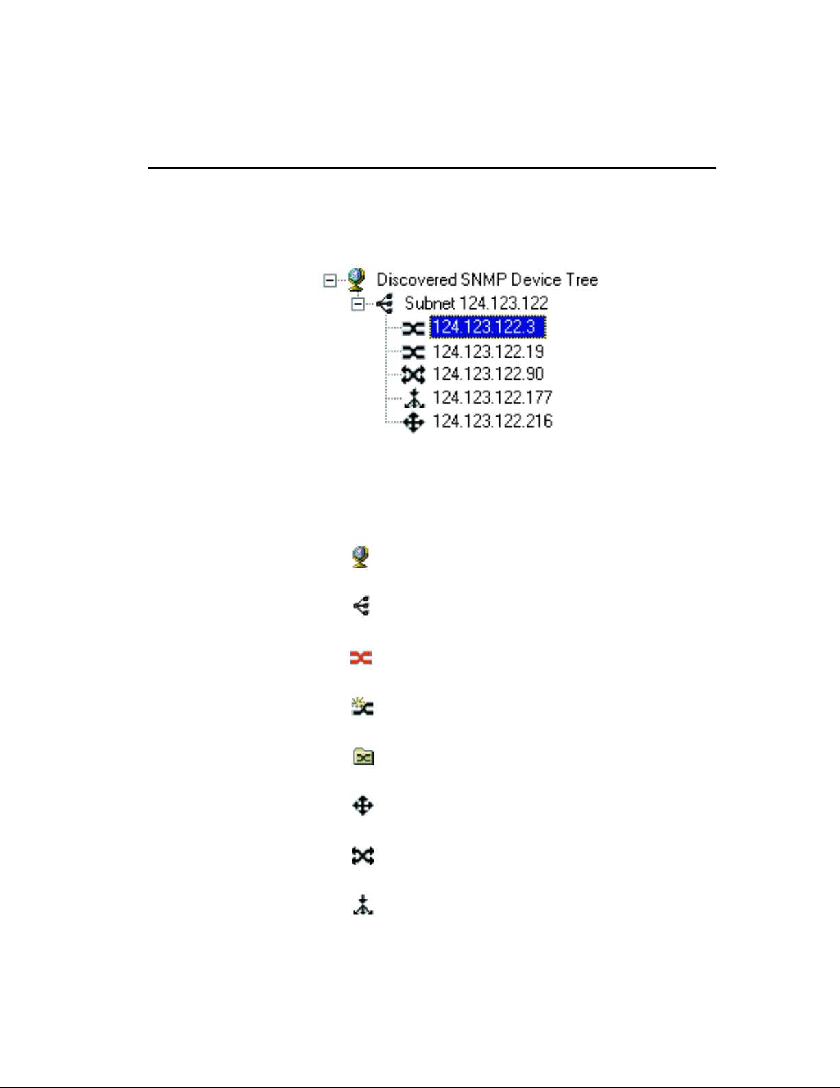
C H A P T E R 3 Using Intel® Device View
network. As it discovers devices, it adds an icon for each device to the
Device Tree on the left side of the screen.
Different states of the 480T routing switch are represented by unique
icons in the Device Tree as indicated below.
Device Tree icons
Device Tree root
Subnet
Intel Switch (if non-responding the icon is red)
Unconfigured Intel Switch
Group of Intel Switches
Intel Router
Intel Switch (Layer 3 capable)
Intel Stackable Hub
27
Page 54

®
Intel
NetStructure™ 480T Routing Switch User Guide
The Device Tree works much like Windows Explorer:
• To expand the root or a subnet, click the (+) next to the icon.
• To collapse the view, click the (-) next to the icon.
• Double-click a device icon to view the device image.
To Add a Device to the Device Tree
1. Right-click anywhere on the Device Tree.
2. When a menu appears, click
3. In the
4. Fill in the other fields, as appropriate.
5. Click
Add Device dialog box, enter the IP address of the switch
want to add.
you
OK.
Add Device.
The new switch’s icon appears in the Device Tree.
To Refresh the Device Tree
1. Right-click anywhere on the Device Tree.
2. When a menu appears, click
Refresh.
Refreshing the Device Tree updates it to show any newly discovered
devices and changes in device status.
To Delete a Device from the Device Tree
1. Right-click the device you want to remove from the Device Tree.
2. Click
Deleting a device from the Device Tree does not affect the actual
device, but only removes the icon from the tree.
Delete on the menu that appears.
To Find a Device in the Device Tree
1. Right-click anywhere on the Device Tree.
2. When a menu appears, click
28
Find.
Page 55

C H A P T E R 3 Using Intel® Device View
3. In the Find Device dialog box, enter the IP address of the device
want to find in the tree.
you
4. Click OK.
The device’s icon is highlighted in the Device Tree.
Losing Contact with a Device
If Intel Device View loses contact with a switch, it replaces the switch
icon with the red non-responding switch icon.
When the red non-responding switch icon appears, you will not be
able to manage the device in Intel Device View.
If you’re unable to ping the device or start a Telnet session, try
accessing the switch’s Local Management. See “Accessing the
Switch” on page 39.
Managing a Switch
To manage a 480T routing switch, double-click the switch icon in the
Device Tree. In the example shown below, the switch was assigned
an IP address of 124.123.122.3.
29
Page 56

®
Intel
NetStructure™ 480T Routing Switch User Guide
The Express 480T Web Device Manager appears in the Intel Device
View window.
For complete information on using Intel Device View, refer to the
program’s online help or see the Intel Device View Help file on the
installation CD-ROM.
Viewing RMON Information
The remote monitoring (RMON) specification is a feature of Intel
Device View that extends Simple Network Management Protocol
(SNMP) functionality to look at traffic patterns over the whole
network instead of merely for an individual device. The 480T routing
switch supports these RMON groups:
• Group 1 Statistics—Monitors utilization and error statistics for
each network segment (100Mbps or 1000Mbps).
• Group 2
variables available in the statistics group.
• Group 3
alarm thresholds for statistics. When a threshold is passed, the
30
History—Records periodic statistical samples from
Alarms—Allows you to set a sampling interval and
Page 57

C H A P T E R 3 Using Intel® Device View
switch creates an event (see below). For example, you might set an
alarm if switch utilization exceeds 30%.
• Group 9
do when an event occurs on the network.
Events can send a trap to a trap-receiving station, place an entry
in the log table, or both. For example, when the switch
experiences an RMON event, it sounds an alarm.
The switch also keeps a log that shows a list of the RMON events
and RMON alarms that have occurred on the switch.
Events—Provides notification and tells the switch what to
To View RMON Statistics
1. In the Device Tree, right-click the switch’s icon and then point to
RMON.
2. Click the RMON option you want to view.
You can also access RMON features by using LANDesk Network
Manager, or an SNMP application that supports RMON, such as
OpenView.
For more information about using RMON to monitor the switch, refer
to the Intel Device View Help file included on the CD-ROM.
31
Page 58

®
Intel
NetStructure™ 480T Routing Switch User Guide
32
Page 59

4
Using Web Device
Manager
Web Device Manager is device-management software running in the
®
NetStructure™ 480T routing switch. It allows you to access the
Intel
switch over a TCP/IP network, using a Web browser that supports frames
and JavaScript
Internet Explorer
Web Device Manager provides a subset of the command-line interface
(CLI) commands available for configuring and monitoring the switch. If
a particular command is not available using Web Device Manager, use the
CLI to access the desired functionality.
To use Web Device Manager, at least one VLAN must be assigned an IP
address.
Enabling and Disabling Web Access
By default, Web access is enabled on the switch. You can restrict the use
of Web access using an access profile.
§
(such as Netscape Navigator§ 3.0 or later, or Microsoft
§
3.0 or later) to manage the system.
For information on creating
an access profile see page
324.
An access profile permits or denies a named list of IP addresses and
subnet masks. To configure Web access to use an access profile, use this
command:
enable web access-profile [<access-profile> | none]
{port <tcp_port_number>}
Page 60

®
Intel
NetStructure™ 480T Routing Switch User Guide
Use the none option to remove a configured access profile.
To display the status of Web access, use this command:
show management
To disable Web access, use this command:
disable web
To re-enable Web access, use this command:
enable web {access-profile [<access-profile> |
none]} {port <tcp_port_number>]
Reboot the system for these changes to take effect.
Setting Up Your Browser
Your browser’s default settings should work well with Web Device
Manager. Apply these recommended settings to improve the
display features and functionality of Web Device Manager:
• After downloading a newer version of the switch image, clear the
browser disk and memory cache to see the updated menu screens.
It is important to clear the cache while at the main Logon screen,
so that all underlying .GIF files are updated.
• Check for newer versions of stored pages by setting the
cache options to the “every visit” setting:
• When using Netscape Navigator, configure the cache to
check for changes
• When using Microsoft Internet Explorer, configure the
Temporary Internet Files to check for newer versions of
stored pages by selecting
• Images must be auto-loaded.
• Use a high-resolution monitor (1024 x 768 recommended) to
maximize the amount of information displayed in the content
frame. You can also use 800 x 600 pixels.
• Maximize viewing space by turning off the browser toolbars.
• Configure the browser to use these recommended fonts:
• Proportional font—Times New Roman
• Fixed-width font—Courier New
34
Every Time you request a page.
Every visit to the page.
Page 61

C H A P T E R 4 Using Web Device Manager
Accessing Web Device Manager
To access the default home page of the switch, enter this URL in
your browser (substituting the actual ip address):
http://<ip_address>
When you access the home page of the system, the Login screen
appears. Enter your user name and password and click OK.
If you have entered the name and password of an administratorlevel account, you have access to all Web Device Manager pages. If
you have used a user-level account name and password, you only
have access to the Statistics and Support information.
If multiple people access the same switch using Web Device
Manager, you might see this error message:
Web:server busy
To correct this situation, try logging out of the switch and logging
in again.
Navigating Web Device Manager
After logging in to the switch, the Web Device Manager home page
appears.
Web Device Manager divides the browser screen into these
sections:
• Task frame
• Content frame
• Stand-alone buttons
Tas k F ra m e
The task frame has two sections: menu buttons and submenu links.
There are four task menu buttons:
• Configuration
• Statistics
• Support
• Logout
35
Page 62

®
Intel
NetStructure™ 480T Routing Switch User Guide
Below the task buttons are options. Options are specific to the task
button that you select. When you select an option, the information
displayed in the content frame changes.
However, when you select a new task button, the content frame does
not change until you select a new option.
Content Frame
When you submit a
configuration page with no
change an asterisk (*) will
appear at the CLI prompt,
even though actual
configuration values have
not changed.
The content frame contains the main body of information in Web
Device Manager. For example, if you select an option from the
Configuration task button, enter configuration parameters in the
content frame. If you select the Statistics task button, statistics are
displayed in the content frame.
Browser Controls
Browser controls include drop-down list boxes, check boxes, and
multi-select list boxes. A multi-select list box has a scrollbar on the
right side of the box. Using a multi-select list box, you can select a
single item, all items, a set of contiguous items, or multiple noncontiguous items. Table 4.1 describes how to make selections from
a multi-select list box.
Table 4.1: Multi-Select List Box Key Definitions
Selection Type Key Sequence
Single item Click the item using the mouse.
All items or
contiguous items
Click the first item, and drag to the last
item.
Contiguous items Click the first item, hold down the Shift
key, and click the last desired item.
Selected noncontiguous items
36
Hold down Ctrl, click the first desired
item, click the next desired item, etc.
Page 63

C H A P T E R 4 Using Web Device Manager
Status Messages
Status messages are displayed at the top of the content frame. There
are four types of status messages:
• Information—Displays information that is useful to know prior
to, or as a result of, changing configuration options.
• Warning—Displays warnings about the switch configuration.
• Error—Displays errors caused by incorrectly configured settings.
• Success—Displays informational messages after you click
Submit. The message displayed reads,
successfully
.
Stand-alone Buttons
At the bottom of some of the content frames is a section that
contains stand-alone buttons. Use these buttons to perform tasks
that are not associated with a particular configuration option. An
example of this is the Reboot Switch button.
Request was submitted
Saving Changes
There are two ways to save your changes in Web Device Manager:
• Select Save Configuration from the Configuration task button,
Switch option.
This field contains a drop-down list box that allows you to
select either the primary or secondary configuration area. After
you select the configuration area, click Submit to save the
changes.
• Click the
If you attempt to log out without saving your changes,
Device Manager
If you select
configuration area.
To change the selected configuration area:
1. Go to the Configuration task button.
2. Select the
Logout button.
Web
prompts you to save your changes.
Yes, the changes are saved to the selected
Switch option.
37
Page 64

®
Intel
NetStructure™ 480T Routing Switch User Guide
Filtering Information
On some pages you can click a Filter button to display a subset of
information for a page. For example, on the OSPF configuration
page, you can configure authentication based on the VLAN, area
identifier, or virtual link.
Once you select a filtering option and click the Filter button, the
form that provides the configuration options displays the available
interfaces in the drop-down menu, based on your filtering selection.
Using the Get Command to
Configure a VLAN
When configuring a VLAN using Web Device Manager, prior to
editing the VLAN configuration, you must first click the Get button
to ensure that subsequent edits are applied to the correct VLAN. If
you do not click the Get button and you submit the changes, the
changes are made to the VLAN that was previously displayed.
If you configure a VLAN and then delete it, the default VLAN is
shown in the VLAN name window, but the VLAN information
contained in the lower portion of the page is not updated. Click the
Get button to update the display.
TFTP Server
Intel Device View provides a TFTP Server utility on the Tools
menu.
38
Page 65

5
Accessing the
Switch
This chapter provides information to help you manage the Intel®
NetStructure™ 480T routing switch, including:
• Understanding the Command Syntax
• Line-Editing Keys
• Command History
• Common Commands
• Configuring Management Access
• Real-time Basic Connectivity Checking
• Methods of Managing the Switch
• Simple Network Management Protocol (SNMP))
For information on using
the save command, see
"Software Upgrade and
Boot Options" on page
419.
To retain configuration changes through a power cycle or reboot, you
must issue a
save command after you have made the change.
Understanding the Command Syntax
This section briefly describes the steps to take when entering a command.
The sections that follow give detailed information for using the
command-line interface.
Page 66

®
Intel
NetStructure™ 480T Routing Switch User Guide
To use the command-line interface (CLI):
Most configuration
commands require that
you have administrator
privileges.
An asterisk (*) in front of
the command-line prompt
indicates you have made
changes that have not
been saved.
1. Enter the command name.
When entering a command at the prompt, ensure that you have the
appropriate privilege level.
2. Enter the parameter name and values, if included.
The value (also known as an argument) specifies how you want
the parameter to be set. Values include numerics, strings, or
addresses, depending on the parameter.
3. After entering the complete command, press Enter.
Syntax Helper
The CLI has a built-in syntax helper. If you are unsure of the
complete syntax for a particular command, enter as much of the
command as possible and press Enter. The syntax helper provides a
list of options for the remainder of the command.
The syntax helper also provides assistance if you have entered an
incorrect command.
Command Completion with Syntax Helper
Use the Tab key to access command completion.
1. Enter a partial command.
2. Press the Tab key to post a list of available options.
3. The cursor appears at the end of the command.
Abbreviated Syntax
Abbreviated syntax is the shortest, most unambiguous, allowable
abbreviation of a command or parameter. Typically, this is the first
three letters of the command. For example, ena is sufficient for the
Enable command.
When using abbreviated syntax, you must enter enough characters
to make the command unambiguous and distinguishable to the
switch.
40
Page 67

C H A P T E R 5 Accessing the Switch
Command Shortcuts
All component names must be unique. Name components using the
create command. When you enter a command to configure a
named component, you do not need to use the keyword of the
component. For example, to create a VLAN, you must enter a
unique VLAN name:
create vlan engineering
After you create the VLAN with a unique name, you can eliminate
the keyword
vlan from all other commands that require the name
to be entered. For example, instead of entering the command:
configure vlan engineering delete port 1,4
you can enter this shortcut:
configure engineering delete port 1,4
Numerical Ranges
Commands that require you to enter one or more port numbers on a
switch use the parameter
<portlist> in the syntax. For example:
port 3
A port list can be a range of numbers, for example:
port 1-3
You can add additional port numbers to the list, separated by a
comma:
port 3,4,6
Names
All named components of the switch configuration must:
• Have a unique name.
• Begin with an alphabetical character.
• Be delimited (separated) by a space, unless enclosed in quotation
marks.
41
Page 68

®
Intel
NetStructure™ 480T Routing Switch User Guide
Symbols
You may see a variety of symbols shown as part of the command
syntax. These symbols explain how to enter the command, and you
do not type them as part of the command itself. Table 5.1
summarizes command syntax symbols. Press the Tab key in the
command line interface for more command options.
Table 5.1: Command Syntax Symbols
Symbol Description
< > Angle brackets Enclose a variable or value. You must specify the variable or value.
For example, in the syntax:
configure vlan <name> ipaddress <ip_address>
you must supply a VLAN name for <name> and an address for
<ip_address> when entering the command. Do not type the angle
brackets.
[ ] Square brackets Enclose a required value or list of required arguments. You can
specify one or more values or arguments. For example, in the syntax:
use image [primary | secondary]
you must specify either the primary or secondary image when
entering the command. Do not type the square brackets.
| Vertical bar Separates mutually exclusive items in a list, one of which must be
entered. For example, in the syntax:
configure snmp community [readonly | readwrite]
<string>
you must specify either the read or the write community string in the
command. Do not type the vertical bar.
{ } Braces Enclose an optional value or a list of optional arguments. You can
specify one or more values or arguments. For example, in the syntax
reboot {<date> <time> | cancel}
you can specify either a particular date and time combination, or the
keyword
cancel to cancel a scheduled reboot. If you do not specify a
value, the system prompt asks if you want to reboot the routing
switch now. Do not type the braces.
42
Page 69

C H A P T E R 5 Accessing the Switch
Line-Editing Keys
Table 5.2 describes the line-editing keys available using the CLI.
Table 5.2: Line-Editing Keys
Key(s) Description
Backspace Deletes characters to the left of the cursor and shifts the remainder
of the line to the left.
Delete or Ctrl + D Deletes character at the cursor position and shifts the remainder of
line to the left.
Ctrl + K Deletes characters from the cursor position to the end of the line.
Ctrl + U Deletes characters from the cursor to the beginning of the line.
Ctrl + W Deletes the previous word.
Left Arrow Moves the cursor to the left.
Right Arrow Moves the cursor to the right.
Home or Ctrl + A Moves the cursor to first character on the line.
End or Ctrl + E Moves the cursor to last character on the line.
Ctrl + L Clears the screen and moves the cursor to the beginning of the line.
Up Arrow or Ctrl + P Displays the previous command in the command history buffer and
places the cursor at the end of the command.
Down Arrow or Ctrl + N Displays the next command in the command history buffer and
places the cursor at the end of the command.
43
Page 70

®
Intel
NetStructure™ 480T Routing Switch User Guide
Command History
The local management software stores the last 49 commands you
entered. You can display a list of these commands by using this
command:
history
Common Commands
Table 5.3 describes common commands used to manage the 480T
routing switch. Commands specific to particular features are
described in detail throughout the guide. For detailed command
information use the Quick Reference Guide that accompanies this
user manual. Press the Tab key in the command line interface for
more command options.
Table 5.3: Common Commands
Command Description
clear session <number> Terminates a Telnet session from the switch.
configure account <username>
{<password>}
configure banner Configures the banner string. You can enter
configure ports [all | mgmt | <portlist>] auto
off {speed [100 | 1000]} duplex [half | full]
44
Configures a user account password.
Passwords can have no characters up to a
maximum of 32 characters. User names and
passwords are case-sensitive.
up to 24 rows of 79-column text that is
displayed before the login prompt of each
session. To terminate the command, apply the
banner then press Enter at the beginning of a
line . To clear the banner, press Enter at the
beginning of the first line.
Manually configures Ethernet port speed and
duplex setting of one or more ports on a
switch.
Page 71

C H A P T E R 5 Accessing the Switch
Table 5.3: Common Commands (continued)
Command Description
configure time <date> <time> Configures the system date and time. The
format is as follows:
mm/dd/yyyy hh:mm:ss
The time uses a 24-hour clock format.
configure timezone <gmt_offset> {autodst |
noautodst}
Configures the time zone information to the
configured offset from Greenwich Mean
Time (GMT) time. The format of
gmt_offset is +/- minutes from GMT time.
Specify:
autodst—Enables automatic daylight
saving time change.
noautodst—Disables automatic daylight
saving time change.
The default setting is
configure vlan <name> ipaddress
<ip_address> {<mask>}
create account [admin | user] <username>
{encrypted} {<password>}
Configures an IP address and subnet mask for
a VLAN.
Creates a user account. The command is
available to admin-level users and users with
RADIUS
§
command authorization. The
username can be between 1 and 32
characters. The password can be between 0
and 32 characters.
create vlan <name> Creates a VLAN.
delete account <username> Deletes a user account.
autodst.
delete vlan <name> Deletes a VLAN.
disable bootp vlan [<name> | all] Disables BOOTP for one or more VLANs.
disable cli-config-logging Disables logging of CLI commands to the
Syslog.
45
Page 72

®
Intel
NetStructure™ 480T Routing Switch User Guide
Table 5.3: Common Commands (continued)
Command Description
disable clipaging Disables pausing of the screen display when
a
show command output reaches the end of
the page.
disable idletimeout Disables the timer that disconnects all
sessions. Once disabled, console sessions
remain open until the switch is rebooted or
you log off. Telnet sessions remain open until
you close the Telnet client.
disable port [all | mgmt | <portlist>] Disables a port on the switch.
disable telnet Disables Telnet access to the switch.
disable web Disables Web access to the switch.
enable bootp vlan [<name> | all] Enables BOOTP for one or more VLANs.
enable cli-config-logging Enables the logging of CLI configuration
commands to the Syslog for auditing
purposes. The default setting is enabled.
enable clipaging Enables pausing of the screen display when
show command output reaches the end of the
page. The default setting is enabled.
enable idletimeout Enables a timer that disconnects all sessions
(both Telnet and console) after
20 (in
minutes) of inactivity. The default setting is
disabled.
enable license full_L3 <license_key> Enables a particular software feature license.
Specify <
The command
license_key> as an integer.
unconfigure switch all
does not clear licensing information. This
license cannot be disabled after it is enabled
on the switch.
46
Page 73

C H A P T E R 5 Accessing the Switch
Table 5.3: Common Commands (continued)
Command Description
enable telnet {access-profile
[<access_profile> | none]} {port
<tcp_port_number>}
Enables Telnet access to the switch. By
default, Telnet is enabled with no access
profile, and uses Transmission Control
Protocol (TCP) port number 23. To cancel a
previously configured access profile, use the
none option.
enable web {access-profile
[<access_profile> | none]} {port
<tcp_port_number>}
Enables Web access to the switch. By default,
Web access is enabled with no access profile,
using TCP port number 80.
Use the
none option to cancel a previously
configured access profile. Reboot the switch
for this command to take effect.
history Displays the previous 49 commands entered
on the switch.
show banner Displays the user-configured banner.
unconfigure switch {all} The unconfigure switch command resets
parameters to factory defaults, except defined
user accounts, and date and time information.
To reset user accounts and date and time,
specify the keyword
all which erases the
selected configuration image in flash
memory and reboots.
47
Page 74

®
Intel
NetStructure™ 480T Routing Switch User Guide
Configuring Management Access
The local management software supports these two levels of
management:
• User
• Administrator
In addition to these management levels, you can optionally use an
external RADIUS server to provide CLI command authorization
checking for each command.
For more information on
RADIUS, refer to "RADIUS
Client" on page 66.”
A user-level account has viewing access to all manageable
parameters, with the exception of these:
• User account database
• SNMP community strings
User Account
With a user-level account you can use the ping command to test
device connectivity, and change the password assigned to the
account name. When you log on the command-line prompt ends
with a (>) sign. For example:
switch480T:2>
Administrator Account
Using an administrator-level account, you can view and change all
routing switch parameters. You can also add and delete users, and
change the password associated with any account name.
As an administrator you can also disconnect a management session
connected through Telnet. If this happens, the user logged on
through the Telnet connection is notified that the session was
terminated.
When you log on with administrator capabilities, the command-line
prompt ends with a (#) sign. For example:
switch480T:18#
48
Page 75

C H A P T E R 5 Accessing the Switch
Prompt Text
The prompt text is taken from the SNMP sysname setting (see
Table 5.8, “SNMP Configuration Commands,” on page 64). The
number that follows the colon indicates the sequential line/
command number.
If an asterisk (*) appears in front of the command-line prompt, it
indicates that you have configuration changes that have not been
saved. For example:
*switch480T:19#
Default Accounts
The switch is configured with two default accounts. as shown in
Table 5.4.
Table 5.4: Default Accounts
Account Name Access Level
Passwords are case
sensitive.
admin This user can access and change all
manageable parameters. The admin account
cannot be deleted.
user This user can view (but not change) almost
all manageable parameters. However, this
user cannot view the user account database
or the SNMP community strings.
Changing the Default Password
Default accounts do not have passwords assigned to them. Userassigned passwords must be between 0 and 32 characters.
To add a password to the default admin account:
1. Log in to the switch using the name admin.
2. At the password prompt, press Enter.
3. Enter this command:
configure account admin
49
Page 76

®
Intel
NetStructure™ 480T Routing Switch User Guide
4. Enter the new password at the prompt.
5. Re-enter the password for verification.
To add a password to the default user account:
1. Log in to the switch using the name admin.
2. At the password prompt, press Enter, or enter the password that
3. Add a default user password using this command:
4. Enter the new password at the prompt.
5. Re-enter the new password at the prompt.
Creating a Management Account
you have configured for the
configure account user
admin account.
If you forget your
password while logged out
of the command-line
interface, contact your
local technical support
representative.
The 480T routing switch can have a total of 16 management
accounts. You can use the default names (admin and user), or you
can create new names and passwords for the accounts. Account
passwords can be between 0 and 32 characters. Do not use Ctrl +
key or Alt + key.
To create a management account:
1. Log in to the switch as admin.
2. At the password prompt, press Enter, or enter the password that
you have configured for the
3. Add a new user account with this command:
create account [admin | user] <username>
4. Enter the password at the prompt.
5. Re-enter the password for verification.
admin account.
Viewing Accounts
To view the accounts you have created, you must have
administrator privileges. Use this command to see the accounts:
show accounts
50
Page 77

C H A P T E R 5 Accessing the Switch
Deleting an Account
To delete an account, you must have administrator privileges. Use
this command to delete an account:
delete account <username>
The account name admin
cannot be deleted.
Domain Name Service Client
The Domain Name Service (DNS) client augments these
commands, to allow them to accept either IP addresses or host
names:
• telnet
• download [bootrom | configuration | image]
• upload configuration
• ping
• traceroute
Also, you can use the nslookup utility to return the IP address of a
host name.
Table 5.5 describes the commands used to configure DNS. Press the
Tab key in the command line interface for more command options.
Table 5.5: DNS Commands
Command Description
configure dns-client add <ipaddress> Adds a DNS name server(s) to the available server
list for the DNS client. You can configure up to three
name servers.
configure dns-client default-domain
<domain_name>
Configures the domain that the DNS client uses if a
fully qualified domain name is not entered. For
example, if the default domain is configured to be
intel.com, executing ping support searches for
support@intel.com.
configure dns-client delete
Removes a DNS server.
<ipaddress>
nslookup <hostname> Displays the IP address of the requested host.
show dns-client Displays the DNS configuration.
51
Page 78

®
Intel
NetStructure™ 480T Routing Switch User Guide
Real-time Basic Connectivity
Checking
Use these commands to check basic connectivity:
• ping
• traceroute
Ping
You can use the ping command to send Internet Control Message
Protocol (ICMP) echo messages to a remote IP device. The
command is available for both the user and administrator privilege
level.
The
ping {continuous} {start-size <start_size> {- endsize <end_size>}} [<ip_address> | <hostname>] {from
<src_address>} {with record-route}
ping
ping command syntax is:
Options for the ping command are described in Table 5.6. Press the
Tab key in the command line interface for more command options.
Table 5.6: Ping Command Parameters
Parameter Description
continuous
Specifies Internet Control Message Protocol
(ICMP) echo messages to be sent
continuously. To interrupt this option, press
any key.
size <n>
Specifies the size of the ICMP request. If both
start-size and end-size are specified,
ICMP requests are transmitted using
increments of 1 byte per packet. If no
size is specified, packets of start-size are
end-
sent.
<ipaddress>
<hostname>
Specifies the IP address of the host.
Specifies the name of the host. To use the
hostname, first configure DNS.
52
Page 79

C H A P T E R 5 Accessing the Switch
Table 5.6: Ping Command Parameters (continued)
Parameter Description
from
Uses the specified source address in the ICMP
packet. If not specified, the address of the
transmitting interface is used.
with
recordroute
Decodes the list of recorded routes and
displays them when the ICMP echo reply is
received.
Traceroute
The traceroute command enables you to trace the routed path
between the switch and a destination endstation. The
command syntax is:
traceroute [<ip_address> | <hostname>] {from
<src_ipaddress>} {ttl <TTL>} {port <port>}
where:
• ip_address is the IP address of the destination endstation.
•
hostname is the host name of the destination endstation. To use
the host name, first configure DNS.
from uses the specified source address in the ICMP packet. If not
•
specified, the address of the transmitting interface is used.
traceroute
See "Using Intel® Device
View" on page 23.
ttl configures the switch to trace up to the time-to-live number
•
of the switch.
•
port uses the specified UDP port number.
Methods of Managing the Switch
You can manage the switch by either connecting a terminal (or
workstation with terminal-emulation software) to the console port
to access the CLI or by using TCP/IP through one of the switch
ports or through the dedicated 10/100 Mbps unshielded twisted pair
(UTP) Ethernet management port to access the switch remotely.
53
Page 80

®
Intel
NetStructure™ 480T Routing Switch User Guide
You can use Telnet, a Web browser, or an SNMP manager to
manage the switch remotely. There can be one console session, one
Web session or eight concurrent Telnet sessions.
Using the Console Interface
You can access the built-in CLI of the 480T routing switch through
the 9-pin RS-232 port located on the back of the switch.
After the connection is established, the switch prompt appears, so
you can log in.
Using the 10/100 UTP Management Port
The 480T routing switch has a dedicated 10/100 Mbps UTP
management port. This port provides dedicated remote access to the
switch using TCP/IP. It supports these management methods:
• Telnet using the CLI interface
• Intel Device View access using a Web browser
• SNMP access using SNMP manager
The management port is a DTE port, and is not capable of
supporting switching or routing functions. The TCP/IP
configuration for the management port is done using the same
syntax as used for VLAN configuration. The VLAN mgmt comes
pre-configured with only the 10/100 Mbps management port as a
member.
You can configure the IP address, subnet mask, and default router
for the VLAN mgmt, using these commands:
• configure vlan mgmt ipaddress <ip_address>/
<subnet_mask>
• configure iproute add default <gateway>
Using Telnet
Most workstations with a Telnet facility can communicate with the
480T routing switch over a TCP/IP network.
Up to eight active Telnet sessions can access the switch
concurrently. If
will time out after 20 minutes of inactivity. If a connection to a
idletimeouts are enabled, the Telnet connection
54
Page 81

C H A P T E R 5 Accessing the Switch
Telnet session is lost inadvertently, the switch terminates the
session within two hours.
Before you can start a Telnet session, you must set up the IP
parameters described in the section "Configuring Switch IP
Parameters" on page 55.. Telnet is enabled by default.
To open the Telnet session, you must specify the IP address of the
device that you want to manage. Check the user manual supplied
with the Telnet facility if you are unsure of how to do this.
After the connection is established, you will see the switch prompt
and you can log in.
Connecting to Another Host Using Telnet
Use this command to Telnet from the current CLI session to another
host:
telnet [<ipaddress> | <hostname>] {<port_number>}
If the TCP port number is not specified, the Telnet session defaults
to port 23. Only VT100 emulation is supported.
Find the switch’s MAC
address on the rear label
of the switch.
Configuring Switch IP Parameters
To manage the routing switch through Telnet connection or by
using an SNMP Network Manager, you must first configure the
switch IP parameters.
Using a BOOTP Server
If you are using IP and you have a Bootstrap Protocol (BOOTP)
server set up correctly on your network, you must add the following
information to the BOOTP server:
• Media Access Control (MAC) address found on the rear label of
the switch (or use the
• IP address
• Subnet address mask (optional)
After this is done, the IP address and subnet mask for the routing
switch is downloaded automatically. You can then start managing
the switch without further configuration.
show switch command)
55
Page 82

®
Intel
NetStructure™ 480T Routing Switch User Guide
You can enable BOOTP on a per-VLAN basis using this command:
enable bootp vlan [<name> | all]
By default, BOOTP is enabled on the default VLAN.
If you configure the 480T routing switch to use BOOTP, the switch
IP address is not retained through a power cycle, even if the
configuration is saved. To retain the IP address through a power
cycle, you must configure the IP address of the VLAN using the
command-line interface, Telnet, or Web interface.
All VLANs within a switch that are configured to use BOOTP to get
their IP address use the same MAC address. Therefore, if you are
using BOOTP relay through a router, the BOOTP server must be
capable of differentiating its relay based on the gateway portion of
the BOOTP packet.
Manually Configuring the IP Settings
For more information on
DHCP/BOOTP relay, refer
to "IP Unicast Routing" on
page 189.
For information on creating
and configuring VLANs,
see "Virtual LANs
(VLANs)" on page 95.
If you are using IP without a BOOTP server, you must enter the IP
parameters for the switch in order for the SNMP Network Manager,
Telnet software, or Web interface to communicate with the device.
IP addresses are always assigned to a VLAN. You can assign
multiple IP addresses to the switch.
To assign IP parameters to the switch:
1. Log in to the switch with administrator privileges.
2. Assign an IP address and subnet mask to a VLAN.
The switch comes configured with a default VLAN named default.
To use Telnet or an SNMP Network Manager, you must have at
least one VLAN on the switch, and it must be assigned an IP address
and subnet mask.
To manually configure the IP settings:
1. Connect a terminal or workstation running terminal-emulation
software to the console port.
2. At your terminal, press Enter one or more times until you see the
login prompt.
3. If you are logging in for the first time, use the default user name
admin to log in with administrator privileges. For example:
56
Page 83

C H A P T E R 5 Accessing the Switch
login: admin
Administrator capabilities enable you to access all switch
functions. The default user names have no passwords assigned.
4. If you have been assigned a user name and password with admin-
istrator privileges, enter them at the login prompt and press Enter.
When you have successfully logged in, the command-line
prompt displays the name of the switch.
5. Assign an IP address and subnetwork mask for the default VLAN
using this command:
configure vlan <name> ipaddress <ipaddress>
{<subnet_mask>}
For example:
configure vlan default ipaddress 123.45.67.8
255.255.255.0
Your changes take effect immediately.
Generally, when configuring any IP addresses for the switch,
you can express a subnet mask using dotted decimal notation, or
classless inter-domain routing notation (CIDR).
CIDR uses a forward slash plus the number of bits in the subnet
mask. Using CIDR notation, the command identical to the one
above would be:
configure vlan default ipaddress 123.45.67.8/24
6. Configure the default route for the switch using this command:
configure iproute add default <gateway>
{<metric>}
For example:
configure iproute add default 123.45.67.1
7. Save your configuration changes so that they are in effect after the
next switch reboot, using this command.
save
8. Log out of the switch using the command:
logout or quit
57
Page 84

®
Intel
NetStructure™ 480T Routing Switch User Guide
Disconnecting a Telnet Session
An administrator-level account can disconnect a management
session that is established through Telnet connection. If this
happens, the user logged in through Telnet is notified that the
session is terminated.
To terminate a Telnet session:
1. Log in to the switch with administrator privileges.
2. Determine the session number of the session you want to termi-
3. Terminate the session by using this command:
Controlling Telnet Access
nate by using this command:
show session
clear session <session_number>
See "Using Access
Profiles" on page 59.
You must be logged in as
an administrator to enable
or disable Telnet.
By default, Telnet services are enabled on the routing switch. You
can restrict Telnet access using an access profile. An access profile
permits or denies a named list of IP addresses and subnet masks. To
configure Telnet to use an access profile, use this command:
enable telnet {access-profile [<access_profile> |
none]} {port <tcp_port_number>}
Use the none option to remove a previously configured access
profile.
To display the status of Telnet, use this command:
show management
To disable Telnet, use this command:
disable telnet
To re-enable Telnet on the switch, use this command at the console
port:
enable telnet
58
Page 85

C H A P T E R 5 Accessing the Switch
Using Access Profiles
An access profile permits or denies a named list of IP addresses and
subnet masks. To use access profiles, first define the list, and then
apply the named list to the desired application.
Access profiles are used by several routing switch features as a way
to restrict access. Applications that use access profiles for remotely
managing the switch are:
• SNMP read-only access
• SNMP read-write access
• Teln et
• Web access
See "Access Policies" on
page 309.
Access profiles can also be used in association with access policies
that control the flow of traffic.
Creating an Access Profile
Do not confuse access
profiles with access
policies.
Table 5.7: Access Profile Configuration Commands
Command Description
configure access-profile <access_profile>
add {vlan <name> | ipaddress <ipaddress>
<mask>}
You can use access profiles to specifically permit or deny users
access to an application. You restrict access by assigning an access
profile to the service that is being used for remote access.
When you create and name an access profile to restrict access to a
certain application, you then need to configure the application to use
the named access profile. Otherwise, no restrictions are applied.
Use the commands listed in Table 5.7 to create and configure access
profiles. For further access profile commands refer to Table 17.3 on
page 335. Press the Tab key in the command line interface for more
command options.
Adds an IP address or VLAN name to the
access profile. The entry must be of the same
type as the access profile (for example, IP
address).
59
Page 86

®
Intel
NetStructure™ 480T Routing Switch User Guide
Table 5.7: Access Profile Configuration Commands (continued)
Command Description
configure access-profile <access_profile>
delete {vlan <name> | ipaddress
Deletes an IP address or VLAN name from the
access profile.
<ipaddress> <mask>}
configure access-profile <access_profile>
mode [permit | deny | none]
Configures the access profile to one of the
following:
permit—Allows the addresses that match the
access profile description.
deny—Denies the addresses that match the
access profile description.
create access-profile <access_profile> type
[as-path] [bgp-community] ipaddress |
ipxret | ipxnode | ipxsap
The default setting is
Creates an access profile. After the access
profile is created, you can add one or more
addresses to it, and you can use the profile to
permit.
control a specific routing protocol.
delete access-profile <access_profile> Deletes an access profile.
show access-profile <access_profile> Displays access profile related information for
the switch.
The subnet mask specified in the access profile command is
interpreted as a reverse mask. A reverse mask indicates the bits that
are significant in the IP address and specifies the part of the address
that must match the IP address to which the profile is applied.
If you configure an IP address as an exact match to be specifically
denied or permitted, use a mask of /32 (for example, 141.251.24.28/
32).
If the IP address represents a subnet address that you want to deny
or permit, then configure the mask to cover only the subnet portion
(for example, 141.251.10.0/24).
If you are using classless subnet masking (CIDR), the same logic
applies, but the configuration is more complex. For example, the
address 141.251.24.128/27 represents any host from subnet
141.251.24.128.
60
Page 87

C H A P T E R 5 Accessing the Switch
Access Profile Rules
These rules apply when using access profiles:
• Only one access profile can be applied to each application.
• The access profile can either permit or deny the entries in the
profile.
• The same access profile can be applied to more than one
application.
Access Profile Example
The following example creates an access profile named testpro, and
denies access for the device with the IP address 192.168.10.10:
create access-profile testpro type ipaddress
configure access-profile testpro mode deny
configure access-profile testpro add ipaddress
192.168.10.10/32
The following command applies the access profile testpro to Telnet:
For more information, refer
to "Using Web Device
Manager" on page 33.
enable telnet access-profile testpro
To view the contents of an access profile, use this command:
show access-profile <access_profile>
To view the Telnet configuration, use this command:
show management
Using Web Device Manager
The Intel Web Device Manager is device-management software
running in the routing switch that enables you to access the switch
over a TCP/IP network using a Web browser.
You should use a Web browser that supports frames (such as
Netscape Navigator
or later) to manage the switch over a TCP/IP network.
Access the default home page of the switch using this command:
http://<ipaddress>
§
3.0 or later, or Microsoft Internet Explorer§ 3.0
61
Page 88

®
Intel
NetStructure™ 480T Routing Switch User Guide
When you access the home page of the switch the Logon screen
appears.
Controlling Web Access
By default, Web access is enabled on the routing switch. You can
restrict access through the Web Device Manager using an access
profile, which permits or denies access to a named list of IP
addresses and subnet masks.
For more information on
assigning an IP address,
refer to "Configuring
Switch IP Parameters" on
page 55.
You can configure Web access to use an access profile using this
command:
enable web {access-profile <access-profile> | none}
{port <tcp_port_number>}
Use the none option to remove a previously configured access
profile.
To display the status of Web access, use this command:
show management
To disable Web access, use this command:
disable web
To re-enable Web access, use this command:
enable web {access-profile <access-profile> | none}
{port <tcp_port_number>}
When you disable or enable Web Device Manager, you must reboot
the switch for the changes to take effect. Apply an access profile
only when Web Device Manager is enabled.
Simple Network Management
Protocol (SNMP)
Any network manager running the Simple Network Management
Protocol (SNMP) can manage the 480T routing switch, provided
the Management Information Base (MIB) feature of the 480T
routing switch is installed correctly on the management station.
Each Network Manager provides its own user interface to the
management facilities.
62
Page 89

C H A P T E R 5 Accessing the Switch
Accessing Switch Agents
To have access to the SNMP agent in the routing switch, at least one
VLAN must have an IP address assigned to it.
For more information on
assigning IP addresses,
refer to Table 5.3 on
page 44.
Supported MIBs
Along with private MIBs, the routing switch supports the MIBs
listed in "Technical Specifications and Supported Limits" on page
431.
Configuring SNMP Settings
You can configure the following SNMP parameters on the routing
switch:
• Authorized trap receivers—An authorized trap receiver can be
one or more network management stations on your network. The
switch sends SNMP traps to all trap receivers. You can have a
maximum of 16 trap receivers configured for each switch. .
• SNMP read access—The ability to read SNMP information can
be restricted through the use of an access profile. An access
profile permits or denies a named list of IP addresses and subnet
masks.
To configure SNMP read access to use an access profile, use the
command:
configure snmp access-profile readonly
[<access_profile> | none]
Use the none option to remove a previously configured access
profile.
• SNMP read/write access—The ability to read and write SNMP
information can be restricted through the use of an access profile.
An access profile permits or denies a named list of IP addresses
and subnet masks.
To configure SNMP read/write access to use an access profile,
use the command:
configure snmp access-profile readwrite
[<access_profile> | none]
Use the none option to remove a previously configured access
profile.
63
Page 90

®
Intel
NetStructure™ 480T Routing Switch User Guide
• Community strings—Allows a simple method of authentication
• System contact (optional)—A text field where you can enter the
• System name—The name you have assigned to this switch. The
• System location (optional)—Use this to enter an optional
Table 5.8 describes SNMP configuration commands. Press the Tab
key in the command line interface for more command options.
between the 480T routing switch and the remote Network
Manager. There are two types of community strings on the switch.
Read community strings provide read-only access to the switch.
The default read-only community string is
community strings provide read and write access to the switch.
The default read-write community string is
eight community strings can be configured on the switch. The
community string for all authorized trap receivers must be
configured on the switch for the trap receiver to receive switchgenerated traps. SNMP community strings can contain up to 127
characters.
name of the person(s) responsible for managing the switch.
default name is
location for this switch.
switch480T.
public. Read-write
private. A total of
Table 5.8: SNMP Configuration Commands
Command Description
configure snmp access-profile readonly
[<access_profile> | none]
configure snmp access-profile readwrite
[<access_profile> | none]
configure snmp add trapreceiver <ipaddress>
community <string>
Assigns an access profile that limits which
stations have read-only access to the switch.
Assigns an access profile that limits which
stations have read-write access to the switch.
Adds the IP address of a specified trap
receiver. The IP address can be a unicast,
multicast, or broadcast address. A maximum
of 16 trap receivers is allowed.
64
Page 91

C H A P T E R 5 Accessing the Switch
Table 5.8: SNMP Configuration Commands (continued)
Command Description
configure snmp community [readonly |
readwrite] {encrypted} <string>
Adds an SNMP read or read/write community
string. The default
string is
public. The default readwrite
community string is
readonly community
private. Each
community string can have a maximum of
127 characters, and can be enclosed by double
quotation marks.
configure snmp delete trapreceiver
[<ip_address> community <string> | all]
Deletes the IP address of a specified trap
receiver or all authorized trap receivers.
configure snmp syscontact <string> Configures the name of the system contact. A
maximum of 255 characters is allowed.
configure snmp syslocation <string> Configures the location of the switch. A
maximum of 255 characters is allowed.
configure snmp sysname <string> Configures the name of the switch. A
maximum of 32 characters is allowed. The
default sysname is the model name of the
device (for example,
sysname appears in the switch prompt.
switch480T). The
disable snmp access Disables SNMP access on the switch.
Disabling SNMP access does not affect the
SNMP configuration (for example,
community strings).
disable snmp traps Prevents SNMP traps from being sent from
the switch. This does not clear the SNMP trap
receivers that have been configured.
enable snmp access Enables SNMP support.
enable snmp traps Enables SNMP trap support.
unconfigure management Restores default values to all SNMP-related
entries.
65
Page 92

®
Intel
NetStructure™ 480T Routing Switch User Guide
Displaying SNMP Settings
To display the SNMP settings configured on the routing switch, use
this command:
show management
This command displays the following information:
• Enable/disable state for Telnet, SNMP, and Web access, along
• SNMP community strings
• Authorized SNMP station list
• SNMP trap receiver list
• RMON polling configuration
• Login statistics
SNMP enhancements allow the ifMIB to display the port number
for physical ports and VLAN name for the VLANs index.
with access profile information
You cannot configure
RADIUS and TACACS+ at
the same time.
66
Authenticating Users
The routing switch uses two methods to authenticate users who
login to the switch:
• RADIUS§ client
• TACACS+ (Terminal Access Controller Access Control System
Plus)
RADIUS Client
Remote Authentication Dial In User Service (RADIUS, RFC 2138)
allows you to authenticate and centrally administer access to
network nodes. The 480T routing switch RADIUS client
implementation enables authentication for Telnet, Web interface, or
console access to the switch.
You can define a primary and secondary RADIUS® server for the
routing switch to contact.
When a user attempts to log on to the switch using Telnet, HTTP,
or the console, the request is relayed to the primary RADIUS server,
Page 93

C H A P T E R 5 Accessing the Switch
and then to the secondary RADIUS server, if the primary does not
respond.
If the RADIUS client is enabled, but access to the RADIUS primary
and secondary servers fail, the routing switch uses its local database
for authentication.
The privileges assigned to the user (admin versus non-admin) at the
RADIUS server take precedence over the configuration in the local
switch database.
Per-Command Authentication Using RADIUS
Use RADIUS to perform per-command authentication. Percommand authentication allows you to define several levels of user
capabilities that determine which set of commands the user has
access to based on the RADIUS username and password.
There is no need to configure any additional switch parameters to
take advantage of this capability. The RADIUS server
implementation automatically negotiates the per-command
authentication capability with the switch.
Configuring RADIUS Client
You can define primary and secondary server communication
information. Also for each RADIUS server, you can specify the
RADIUS port number to use when talking to the RADIUS server.
The default port value is 1645. The client IP address is the IP
address used by the RADIUS server for communicating with the
480T routing switch.
RADIUS commands are described in Table 5.9. Press the Tab key
in the command line interface for more command options.
67
Page 94

®
Intel
NetStructure™ 480T Routing Switch User Guide
Table 5.9: RADIUS® Commands
Command Description
configure radius [primary | secondary] server
[<ipaddress> | <hostname>] {<udp_port>}
client-ip <ipaddress>
configure radius [primary | secondary]
shared-secret {encrypted} <string>
configure radius-accounting [primary |
secondary] shared-secret {encrypted}
<string>
Configures the primary and secondary
RADIUS
§
server. Specify the following:
• [primary | secondary]—Either the
primary or secondary RADIUS server.
•
[<ipaddress> | <hostname>]—The IP
address or host name of the server being
configured.
<udp_port>—The UDP port to use to
•
contact the RADIUS server. The default
UDP port setting is 1645.
client-ip <ipaddress>—The IP address
•
used by the switch to identify itself when
communicating with the RADIUS server.
The RADIUS server defined by this command
is used for user-name authentication and CLI
command authentication.
Configures the authentication string used to
communicate with the RADIUS server.
Configures the authentication string used to
communicate with the RADIUS accounting
server.
disable radius Disables the RADIUS client.
disable radius-accounting Disables RADIUS accounting.
68
Page 95

C H A P T E R 5 Accessing the Switch
Table 5.9: RADIUS® Commands (continued)
Command Description
configure radius-accounting [primary |
secondary] server [<ipaddress> |
<hostname>] {<udp_port>} client-ip
<ipaddress>
Configures the RADIUS accounting server.
Specify the following:
• [primary | secondary]—Either the
primary or secondary RADIUS server.
[<ipadress> | <hostname>]—The IP
•
address or host name of the server being
configured.
<udp_port>—The UDP port to use to
•
contact the RADIUS server. The default
UDP port setting is 1646.
client-ip <ipaddress>—The IP address
•
used by the switch to identify itself when
communicating with the RADIUS server.
The accounting server and the RADIUS
authentication server can be the same.
enable radius Enables the RADIUS client. When enabled, all
Web and CLI logins are sent to the RADIUS
servers for authentication. When used with a
RADIUS server that supports routing switch
CLI authorization, each CLI command is sent
to the RADIUS server for authentication
before it is executed.
enable radius-accounting Enables RADIUS accounting. The RADIUS
client must also be enabled.
show radius Displays the current RADIUS and RADIUS
accounting client configuration and statistics.
show radius-accounting Displays the current RADIUS accounting
client configuration and statistics.
69
Page 96

®
Intel
NetStructure™ 480T Routing Switch User Guide
RADIUS RFC 2138 Attributes
The RADIUS RFC 2138 optional attributes supported are:
• User-Name
• User-Password
• Service-Type
• Login-IP-Host
Configuring TACACS+
Terminal Access Controller Access Control System Plus
(TACACS+) is a means for providing authentication, authorization,
and accounting on a centralized server, similar in function to a
RADIUS client.
The routing switch version of TACACS+ is used to authenticate
prospective users who are attempting to administer the switch.
TACACS+ is used to communicate between the switch and an
authentication database.
You cannot use TACACS+
and RADIUS at the same
time.
70
You can configure two TACACS+ servers, specifying the primary
server address, secondary server address, and UDP port number to
be used for TACACS+ sessions.
Table 5.10 describes the commands that are used to configure
TACACS+. Press the Tab key in the command line interface for
more command options.
Page 97

C H A P T E R 5 Accessing the Switch
Table 5.10: TACACS+ Commands
Command
configure tacacs [primary | secondary] server
[<ipaddress> | <hostname>] {<udp_port>}
client-ip <ipaddress>
configure tacacs [primary | secondary]
shared-secret {encrypted} <string>
configure tacacs-accounting [primary |
secondary] server [<ipaddress> |
<hostname>] {<udp_port>} client-ip
<ipaddress>
Description
Configures the server information for a
TACACS+ server. Specify the following:
• primary | secondary—Specifies
primary or secondary server configuration.
To remove a server, use the address
0.0.0.0.
<ipaddress> | <hostname>—The IP
•
address or hostname of the TACACS+
server.
<udp_port>—Optionally specifies the
•
UDP port to be used.
•
client-ip—Specifies the IP address used
by the switch to identify itself when
communicating with the TACACS+ server.
Configures the shared secret string used to
communicate with the TACACS+ server.
Configures the TACACS+ accounting server.
You can use the same server for accounting
and authentication.
configure tacacs-accounting [primary |
secondary] shared-secret {encrypted}
<string>
Configures the shared secret string used to
communicate with the TACACS+ accounting
server.
disable tacacs Disables TACACS+.
disable tacacs-accounting Disables TACACS+ accounting.
disable tacacs-authorization Disables CLI command authorization.
enable tacacs Enables TACACS+. Once enabled, all Web
and CLI logins are sent to one of the two
TACACS+ servers for login name
authentication and accounting.
71
Page 98

®
Intel
NetStructure™ 480T Routing Switch User Guide
Table 5.10: TACACS+ Commands (continued)
Command
enable tacacs-accounting Enables TACACS+ accounting. If accounting
enable tacacs-authorization Enables CLI command authorization. When
show tacacs Displays the current TACACS+ configuration
show tacacs-accounting Displays the current TACACS+ accounting
unconfigure tacacs {server [primary |
secondary]}
unconfigure tacacs-accounting {server
[primary | secondary]}
Description
is used, the TACACS+ client must also be
enabled.
enabled, each command is transmitted to the
remote TACACS+ server for authorization
before the command is executed.
and statistics.
client configuration and statistics.
Unconfigures the TACACS+ client
configuration.
Unconfigures the TACACS+ accounting
client configuration.
Simple Network Time Protocol
(SNTP)
Therouting switch supports the client portion of the Simple
Network Time Protocol (SNTP) Version 3 based on RFC1769. The
switch can use SNTP to update and synchronize its internal clock
from a Network Time Protocol (NTP) server.
When SNTP is enabled, the switch sends out a periodic query to the
indicated NTP server, or the switch listens to broadcast NTP
updates. The routing switch also supports the configured setting for
Greenwich Mean time (GMT) offset and the use of daylight saving
time.
72
Page 99

C H A P T E R 5 Accessing the Switch
Configuring and Using SNTP
To use SNTP:
1 Identify the host(s) that are configured as NTP server(s).
2 Identify the preferred method for obtaining NTP updates.
The options are for the NTP server to send out broadcasts,
or for switches using NTP to query the NTP server(s)
directly. A combination of both methods is possible.
3 Configure the Greenwich Mean Time (GMT) offset and day-
light saving time preference. NTP updates are distributed
using GMT time.
To properly display the local time in logs and other
timestamp information, the switch should be configured with
the appropriate offset to GMT based on geographical
location. Table 5.11 describes GMT offsets.
The command syntax to configure GMT offset and usage of
daylight saving time is as follows:
configure timezone <GMT_offset> {autodst |
noautodst}
The GMT_OFFSET is in +/
- minutes from the GMT
time. You can enable or
disable Automatic daylight
saving time (DST)
changes. The default
setting is enabled.
4 Enable the SNTP client using this command:
enable sntp-client
Once enabled, the switch sends out a periodic query to the
NTP servers (if configured) or listens to broadcast NTP
updates from the network. The network time information is
automatically saved in the on-board real-time clock.
5 If you would like this switch to use a directed query to the
NTP server, configure the switch to use the NTP server(s). If
the switch listens to NTP broadcasts, skip this step. To configure the 480T routing switch to use a directed query, use this
command:
configure sntp-client [primary | secondary]
server [<ip_address> | <hostname>]
NTP queries are first sent to the primary server. If the
primary server does not respond within one second, or if it is
not synchronized, the switch queries the secondary server (if
configured).
73
Page 100

®
Intel
NetStructure™ 480T Routing Switch User Guide
If the switch cannot obtain the time, it restarts the query
process. Otherwise, the switch waits for the
update interval
6 Optionally, you can change the interval for which the SNTP
client updates the real-time clock of the switch using this command:
configure sntp-client update-interval <seconds>
The default sntp-client update-interval value is 64
7 You can verify the configuration using these commands:
show sntp-client
8 This command provides configuration and statistics associ-
ated with SNTP and its connectivity to the NTP server:
show switch
This command indicates the GMT offset, daylight saving
time, and the current local time.
Table 5.11: Greenwich Mean Time Offsets
sntp-client
before querying again.
GMT
Offset in
Hours
+0:00 +0 GMT - Greenwich Mean
GMT
Offset in
Minutes
Common Time Zone References Geographical Reference
London, England; Dublin,
UT or UTC - Universal
(Coordinated)
WET - Western European
Ireland; Edinburgh, Scotland;
Lisbon, Portugal; Reykjavik,
Iceland; Casablanca, Morocco
-1:00 -60 WAT - West Africa Cape Verde Islands
-2:00 -120 AT - A zore s Mid-Atlantic
-3:00 -180 Brasilia, Brazil; Buenos Aires,
Argentina; Georgetown,
Guyana;
-4:00 -240 AST - Atlantic Standard Caracas, La Paz
-5:00 -300 EST - Eastern Standard Bogota, Columbia; Lima, Peru;
New York, NY, USA;
74
 Loading...