

Page 1
Intel® Express 460T
Standalone Switch
User Guide
Page 2

Copyright © 2001, Intel Corporation. All rights reserved.
Intel Corporation, 5200 NE Elam Young Parkway, Hillsboro OR 97124-6497
Intel Corporation assumes no responsibility for errors or omissions in this manual. Nor does Intel make any commitment to update the
information contained herein.
Intel is a trademark or registered trademark of Intel Corporation or its subsidiaries in the United States and other countries.
* Other brands and names may be claimed as the property of others.
Fifth Edition June 2001 746438-003
Page 3

CONTENTS
Intel Express 460T Standalone Switch Users Guide
Contents
1: Setting Up the Intel® Express 460T
Standalone Switch
Overview ................................................................................... 1
Management .............................................................................. 1
Switch Features ......................................................................... 2
Module Features ........................................................................ 3
Port LEDs .................................................................................. 4
Status LEDs ............................................................................... 4
Crossover Button....................................................................... 5
Connection Guidelines .............................................................. 5
Installing a Module.................................................................... 6
Module A LEDs ........................................................................ 7
Configuring Modules ................................................................ 7
Media Requirements.................................................................. 8
Testing a Cable .......................................................................... 9
Straight-through vs. Crossover Cables ...................................... 10
2: Using the Intel Express 460T Standalone Switch
Overview ................................................................................... 11
What is a Switch? ...................................................................... 12
Sample Configurations .............................................................. 13
Flow Control ............................................................................. 14
Spanning Tree Protocol ............................................................. 14
Tagged Frames .......................................................................... 15
Priority....................................................................................... 15
Link Aggregation ...................................................................... 16
Virtual LANs (VLANs)............................................................. 17
GARP VLAN Registration Protocol (GVRP)........................... 21
Internet Group Multicast Protocol (IGMP) ............................... 22
3: Using Intel® Device View
Overview ................................................................................... 23
Installing Intel Device View...................................................... 24
Starting Intel Device View ........................................................ 25
Installing a New Device ............................................................ 25
i
Page 4

CONTENTS
Intel Express 460T Standalone Switch Users Guide
Using the Device Tree ............................................................... 26
Managing a Switch .................................................................... 29
Viewing RMON information .................................................... 30
4: Using the Web Device Manager
Accessing the Web Device Manager......................................... 32
Navigating the Web Device Manager ....................................... 33
Using Management Screens ...................................................... 34
Configuring the Switch’s IP Settings ........................................ 35
Configuring a Port ..................................................................... 36
Managing User Accounts .......................................................... 37
Configuring VLANs.................................................................. 39
Link Aggregation ...................................................................... 45
Static MAC Addresses .............................................................. 46
Configuring Community Strings and Trap Receivers ............... 47
Monitoring Switch Activity ...................................................... 48
Viewing/Changing Switch Information .................................... 49
Updating Switch Firmware ....................................................... 50
Saving Configuration Changes and Logging Out ..................... 52
5: Using Local Management
Overview ................................................................................... 53
Accessing Local Management................................................... 53
Logon Screen............................................................................. 54
Navigation ................................................................................. 55
Main Menu (Top Screen) .......................................................... 56
Configure Device ...................................................................... 57
Configure IP Address ................................................................ 58
Port Configuration..................................................................... 59
Module Port Settings ................................................................. 60
Switch Settings .......................................................................... 61
Configure Advanced Switch Settings........................................ 62
Configure Spanning Tree Protocol............................................ 63
Configure Spanning Tree for Ports ........................................... 65
Forwarding and Filtering........................................................... 66
Configure IGMP Snooping ....................................................... 67
ii
Page 5

CONTENTS
Intel Express 460T Standalone Switch Users Guide
Configure Static MAC Addresses ............................................. 68
Configure Port Security............................................................. 69
Configure MAC Address Filtering............................................ 71
Configure Ethernet Multicast Filtering ..................................... 72
Ethernet Multicast Filtering (Ports)........................................... 73
Port Mirroring ........................................................................... 74
Link Aggregation ...................................................................... 75
Broadcast Storm Control ........................................................... 76
Configure Management Menu................................................... 77
Community Strings & Trap Receivers ...................................... 78
User Accounts ........................................................................... 79
Managing User Accounts .......................................................... 80
Update Firmware and Config Files ........................................... 82
Reset and Console Options........................................................ 83
Configure VLAN Operation Mode ........................................... 84
Port-based VLANs .................................................................... 85
Add a Port-based VLAN ........................................................... 86
Edit/Delete a Port-based VLAN................................................ 87
Change Port Membership in a VLAN ....................................... 88
MAC-Based VLANs ................................................................. 89
Add a MAC-Based VLAN ........................................................ 90
Edit/Delete a MAC-Based VLAN............................................. 91
Edit a MAC-based VLAN ......................................................... 92
To create a MAC-Based VLAN ................................................ 93
Configure 802.1Q VLANs ........................................................ 94
Add an IEEE 802.1Q VLAN (Configure Port Membership) .... 95
Add an IEEE 802.1Q VLAN (Configure Port Tagging)........... 96
Configure PVID for Untagged/Priority Traffic......................... 97
Configuring 802.1Q VLANs ..................................................... 98
Edit/Delete 802.1Q VLANs ...................................................... 100
Edit an IEEE 802.1Q VLAN ..................................................... 101
Edit an IEEE 802.1Q VLAN (Configure Port Tagging) ........... 102
Configure VLAN ID for Untagged Traffic ............................... 103
GVRP and Ingress Filter Settings ............................................. 104
Monitor (Network Statistics)..................................................... 105
Switch Overview ....................................................................... 106
iii
Page 6

CONTENTS
Intel Express 460T Standalone Switch Users Guide
Port Traffic Statistics................................................................. 107
Port Error Statistics ................................................................... 109
Packet Analysis ......................................................................... 111
IGMP Snooping Status.............................................................. 112
Browse Address Table............................................................... 113
VLAN and GVRP Status........................................................... 115
Tools.......................................................................................... 116
Switch Event Log ...................................................................... 117
Ping a Device............................................................................. 118
Upload Configuration Image File.............................................. 119
Appendix A: Technical Info
What is a configuration file? ..................................................... 121
Sample Configuration File ........................................................ 122
BOOT Menu.............................................................................. 124
List of Factory Defaults............................................................. 125
Troubleshooting/FAQs.............................................................. 126
Locating MIB files .................................................................... 127
Regulatory Information ............................................................. 128
Index 137
Intel Customer Support 143
iv
Page 7

Setting Up the Intel
Express 460T
®
1
Standalone Switch
Overview
This guide provides information on configuring and managing the Intel
Express 460T Standalone Switch and is organized into these chapters:
• Chapter 1 - Information on the switch hardware and optional modules
• Chapter 2 - Information on using the switch in a LAN and advanced
features like link aggregation and virtual LANs (VLANs)
• Chapter 3 - How to use Intel Device View
• Chapter 4 - How to use Web Device Manager
• Chapter 5 - How to use Local Management
Management
Through the switch’s built-in management you can configure the device and
monitor network health. There are several methods for managing this
switch; you can use one method or any combination.
• SNMP management applications like Intel Device View, LANDesk
Network Manager, or Hewlett Packard OpenView* are tailored for Intel
products and show a graphical representation of the device (with the use
of the proper MIB).
®
®
• Onboard management allows control over the device without using an
SNMP application. The Web Device Manager pro vides a graphical
interface while Local Management is a menu-driven interface.
• Other SNMP-compliant applications can manage 460T switches if
you compile the switch’s MIB f iles into that application.
1
Page 8
CHAPTER 1
Intel Express 460T Standalone Switch Users Guide
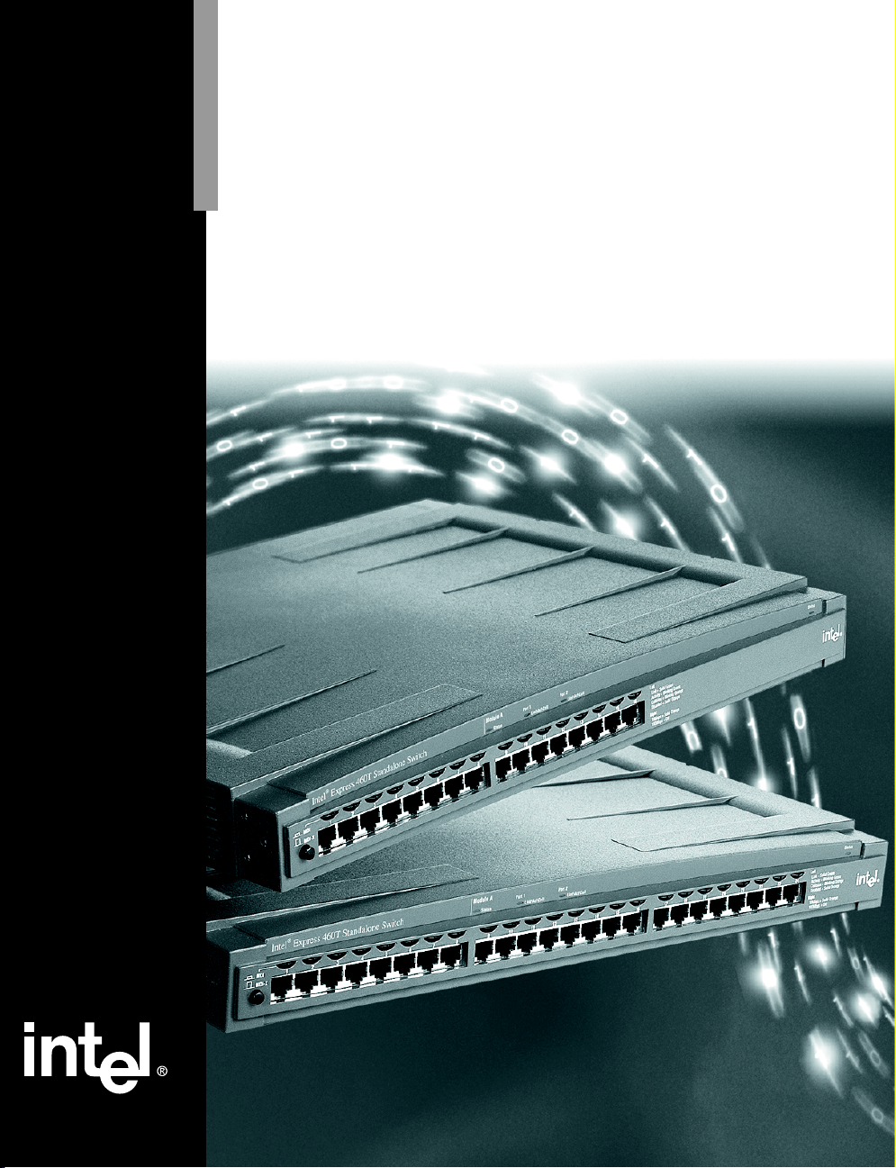
Switch Features
The following diagrams show the major features of the 16-port and 24-port
versions of the 460T Standalone Switches.
16-port 460T Switch (Product Code ES460T16)
Module A
Intel® Express 460T Standalone Switch
MDI
12345678
MDI-X
Port 1 Port 2
Link\Act\Coll
Link\Act\Coll
Status
910111213141516
Left
Link = Solid Green
Activity = Blinking Green
Collision = Blinking Orange
Right
10Mbps = Solid Orange
100Mbps = Off
Status
MDI/MDI-X
button
LEDs
Module LEDs
PortPort
Status LED
24-port 460T Switch (Product Code ES460T24)
Module A
Intel® Express 460T Standalone Switch
MDI
12345678
MDI-X
MDI/MDI-X
button
LEDs
Port 1 Port 2
Link\Act\Coll
Link\Act\Coll
Status
910111213141516 1718192021222324
Module LEDs
PortPort
Left
Link = Solid Green
Activity = Blinking Green
Collision = Blinking Orange
Right
10Mbps = Solid Orange
100Mbps = Off
Status LED
Back of 16-port and 24-port 460T Switch
AC Input
100-240 VAC
50Hz-60Hz
1.5A max
AC Power
Plug
• Auto-negotiates speed, duplex, and flow control—10 Mbps or 100 Mbps
009027390008
MAC Address
address
Local Management
EIA 232
Console: 9600-8-N-1
Serial
Port
Module A
Module A slotMAC
per port.
• Half-duplex and full-duplex flow control.
• One expansion slot for the optional 100FX, 1000SX, 1000LX, or 1000T module.
• Configure port settings manually through management.
• Access menu-driven Local Management through the serial port or a Telnet session.
• Access the graphic, Web-based, Web Device Manager through a Web browser.
Status
2
Page 9

CHAPTER 1
1000T Module for
Intel
®
Express
460T Switch
Port 1
Setting up the Switch
460T Switch Setup
Module Features
Both the 16-port and 24-port versions of the 460T Standalone Switches can
accept a module to provide additional functionality.
100Base-FX Fiber Module (Product Code ES460MFX)
Port 1
TX RX
Port 2
TX RX
100FX Module for
®
Express
Intel
460T Switch
Fiber Ports
• Connects to 100Base-FX devices (such as a switch or server) at full- or half-duplex.
• Extends network diameter up to 400 m (half-duplex) or 2000 m (full-duplex).
1000Base-SX Gigabit Module (Product Code ES460MSX)
1000Base-LX Gigabit Module (Product Code ES460MLX)
Port 1
TX RX
1000SX Module for
Intel® Express
460T Switch
Fiber Ports
Port 1
TX RX
1000LX Module for
Intel® Express
460T Switch
• Connects to 1000Base-SX or 1000Base-LX devices at full-duplex.
• SX module extends network diameter 260 m to 550 m (depending on type of fiber).
• LX module extends network diameter 550 m to 5000 m (depending on type of fiber).
1000Base-T Gigabit Module (Product Code ES460MT)
Ethernet Port
• Connects at 100 Mbps at full-duplex or half-duplex, or 1000 Mbps at full-duplex.
• Extends network diameter up to 100 m.
3
Page 10
CHAPTER 1
Intel Express 460T Standalone Switch Users Guide
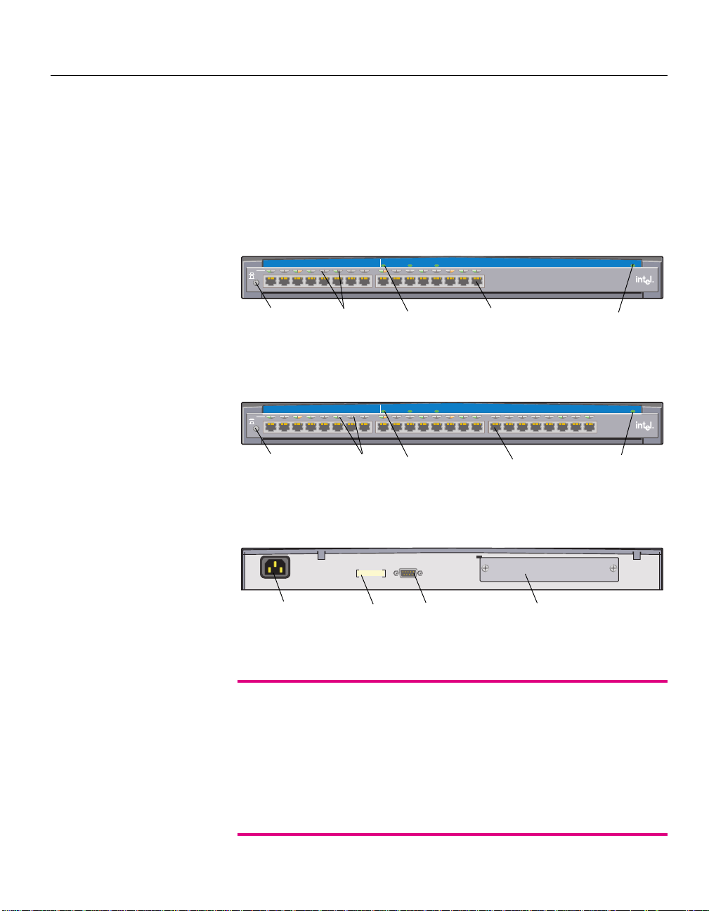
Port LEDs
The LEDs above each port indicate port status, individual port speed, and
port activity.
5678
Left LED
Port Activity
(Green/Orange)
LED Status Meaning
Right LED
Port Speed
(Orange)
Left Solid green
1
Device linked.
Blinking green Receiving activity on that port.
Blinking orange A collision was detected on this segment.
Off No link detected.
Right Solid orange Device connected at 10 Mbps.
Off Device connected at 100 Mbps.
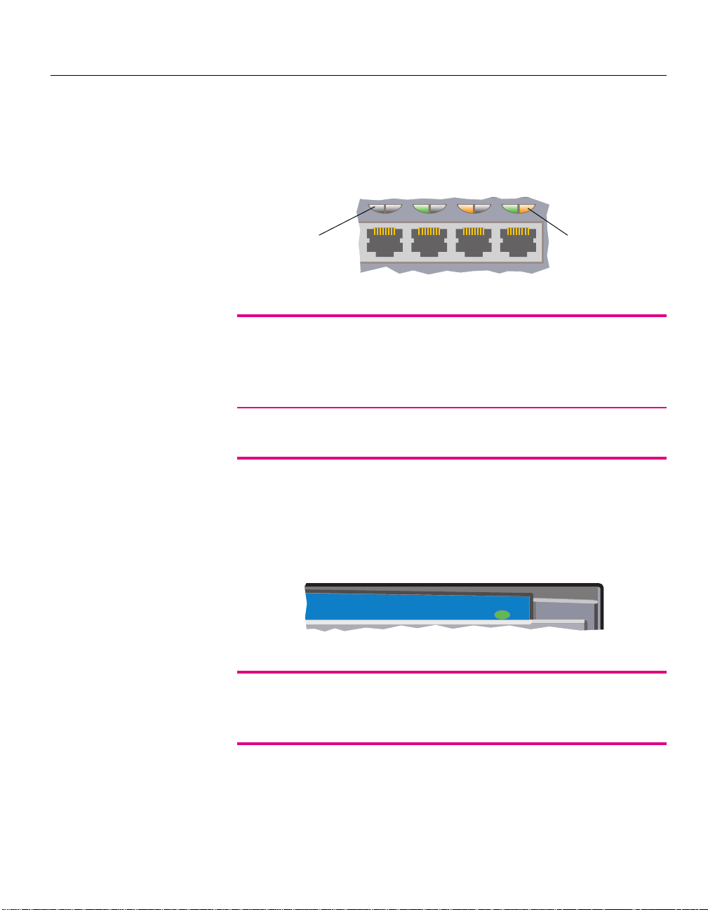
Status LEDs
The switch status LED is located above the port LEDs. This LED indicates
the condition of the switch.
Status
LED Status Meaning
Status Orange Switch is performing diagnostics.
Green Diagnostics have passed, the switch is ready.
2
Red
Diagnostics have failed.
_________________________________________________
1
If the left LED is solid green, but there is no activity when you try to ping a device
connected to that port, the port is probably disabled through management. Re-enable the
port and try again.
2
When the switch is first powered on, the Status LED is red for a couple of seconds before
the diagnostic mode starts, then it turns orange.
4
Page 11
CHAPTER 1
o
Setting up the Switch
460T Switch Setup
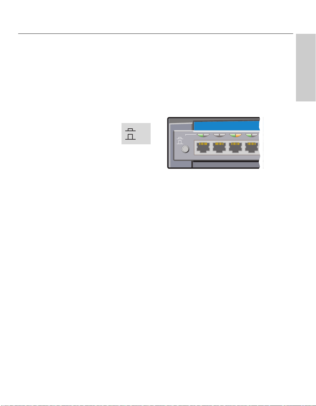
Crossover Button
The 460T switch has a button that toggles port 1 from MDI-X to MDI. With
the button depressed (MDI) you can to connect to another switch or a hub
without using a crossover cable. For more information, see pages 9-10.
MDI
MDI-X
Intel® Express 460T Standal
MDI
1234
MDI-X
Connection Guidelines
General
• The 460T switch can auto-negotiate port speed and can operate at 10
Mbps or 100 Mbps per port. The switch matches the highest possible
speed of an attached device.
• The 460T switch can auto-negotiate port duplex and can operate at halfduplex or full-duplex.
Cabling
• Use Category 5 unshielded twisted-pair (CAT 5 UTP) cable when
connecting 100 Mbps devices to the switch.
• Use Category 3, 4, or 5 unshielded twisted-pair (CAT 3, 4, or 5 UTP)
cable when connecting 10 Mbps devices to the switch.
• Limit the cable length between devices to 100 meters (330 feet).
• Use a straight-through cable to connect the switch to a server or
workstation. For more information on cabling, see pages 9 and 10.
• To connect to another switch or hub use a crossover cable on any port,
or set port 1 to MDI and use a straight-through cable.
5
Page 12
CHAPTER 1
Intel Express 460T Standalone Switch Users Guide
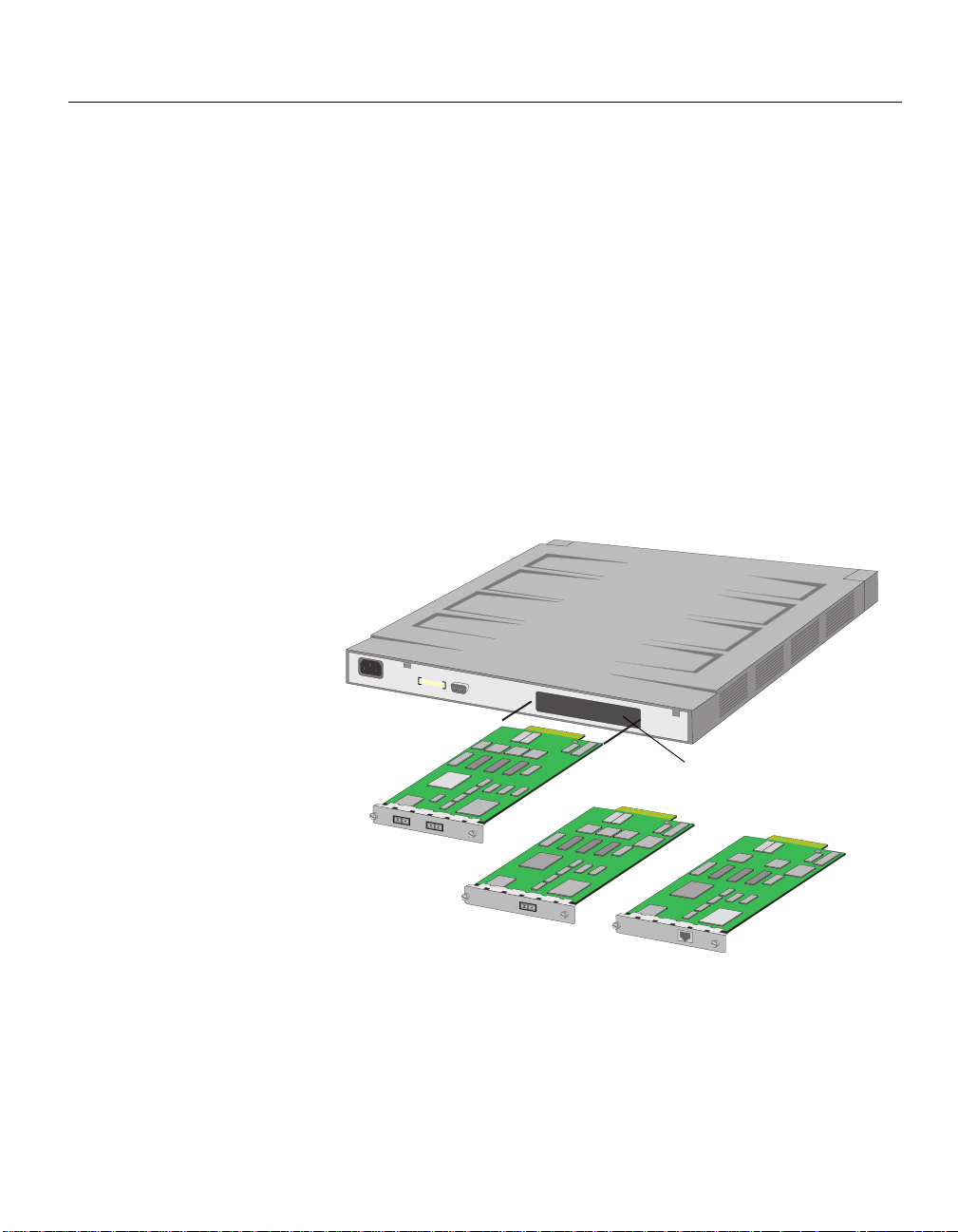
Installing a Module
You can install optional modules only in the Module A slot located at the
back of the switch. Use the LEDs on the front of the switch to check the
module’s status.
To install the module in the switch
1 Unplug the power cord from the switch. Remove the panel from the
expansion slot labeled Module A.
2 Align the module with the card guides inside the switch and slide the
module into the slot. Press firmly to connect the module and secure it
with the retaining screws.
3 Plug in the power cord.
Module A slot
100FX Module
1000SX Module or
1000LX Module
6
1000T Module
Page 13

CHAPTER 1
Setting up the Switch
460T Switch Setup
Module A LEDs
The LEDs are located on the front of the switch above ports 9-16. These
LEDs provide information about the 100FX, 1000SX, or 1000LX module
such as the module’s status, link, port activity, and collisions.
Module A
Status
8
9 1011121314151
Port 1 Port 2
Link\Act\Coll
Link\Act\Coll
LED Status Meaning
Status Solid green Module is present and functioning.
Off No module present.
Link\Act\Coll Solid green Device linked.
Blinking green Receiving activity on that port.
Blinking orange A collision was detected on this segment.
Off No link detected.
When you are using the 1000SX, 1000LX, or 1000T module, only the port 1
LED will blink and show activity because the module has only one port.
Configuring Modules
Generally, you do not need to make any changes to the optional modules
because they are designed to configure themselves automatically for the
attached device. However, you might need to configure the modules in order
to communicate with older devices. You can use the Local Management or
Web Device Manager to configure the 100FX, 1000SX, 1000LX, or 1000T
modules. See Chapter 4 for more information about the Web Device
Manager, and Chapter 5 for more information about Local Management.
7
Page 14

CHAPTER 1
NOTE:
100 meters = 330 feet
200 meters = 660 feet
500 meters = 1,650 feet
2 km = 2000 meters = 6,600 feet
5 km = 5000 meters = 16,500 feet
Intel Express 460T Standalone Switch Users Guide
Media Requirements
Incorrect cabling is often the cause of network performance problems. The
next two pages provide information about how to make sure your cabling is
correct.
100Base-TX
The 100Base-TX Fast Ethernet specification requires that you use CAT 5
UTP cabling to operate at 100 Mbps. If you use lower-grade cabling (CAT 3
or CAT 4), you may get a connection, but also experience data loss or slow
performance. The limit is 100 meters between any two devices.
10Base-T
The 10Base-T Ethernet specification lets you use CAT 3, CAT 4, or
CAT 5 UTP cabling. The limit is 100 meters between any two devices.
100Base-FX
The optional Fiber Module lets you connect to a switch at distances up to
400 meters (hubs up to 160 m) at half-duplex or 2 km at full-duplex. Use
62.5/125 µm multimode fiber optic cable with an SC-type fiber optic
connector.
1000Base-T
The 1000Base-T Gigabit specification requires that you use CAT 5 UTP
cabling to operate at 1000 Mbps. If you use a lower grade cabling you will
experience either no connection or extreme data loss. The maximum
distance between any two devices is 100 meters.
1000Base-SX/1000Base-LX
The optional 1000Base-SX and 1000Base-LX Gigabit Modules provide a
high-speed connection to another device at distances up to 5 km. The
maximum distance depends on the type of cable used. Refer to the following
table for a list of cable types and maximum distances. Use cables with an
SC-type fiber optic connector.
8
Page 15

CHAPTER 1
Setting up the Switch
460T Switch Setup
Selecting the right cable
Media Type Cabling Used Maximum distance
100Base-FX Module 62.5/125
(full-duplex)
100Base-FX Module 62.5/125
(half-duplex) router, switch, or PC)
1000Base-T\100Base-TX Category 5 (CAT 5) unshielded 100 m
(Gigabit) Module twisted pair cable
1000Base-SX 50/125 µm multimode 550 m
(Gigabit) Module 62.5/125 µm multimode 260 m
1000Base-LX 50/125 µm multimode 550 m
(Gigabit) Module 62.5/125 µm multimode 550 m
9/125 µm singlemode 5,000 m
µm multimode 2,000 m
µm multimode (160 m to hub, 400 m to
Testing a Cable
When using a 100Base-TX module, you can quickly check the cable’s link
integrity by plugging one end into port 1 and the other end into port 2. Make
sure the crossover (MDI/MDI-X) button is out. Check the Activity LEDs for
ports 1 and 2. If the LEDs are on, you have a functioning crossover cable.
If the LEDs are off, push the MDI/MDI-X button in. If the Activity LEDs
for ports 1 and 2 turn on, you have a functioning straight-through cable.
However, if the LEDs remain off, you probably have a bad cable.
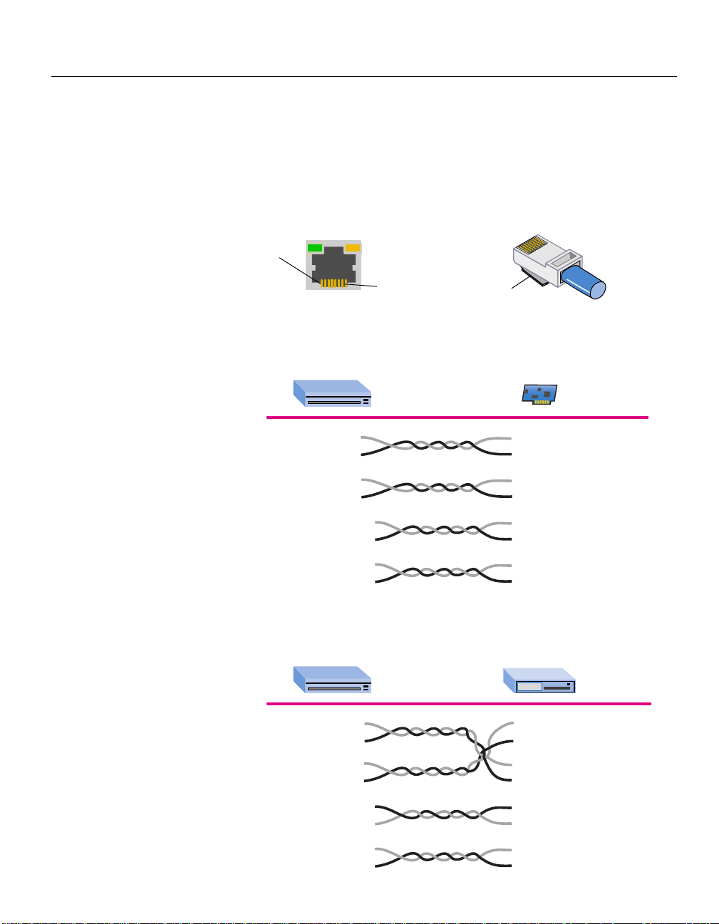
If a cable passes these tests, but the network connection is slow, verify that
wires 1, 2 and 3, 6 on the cable are twisted pairs, as shown in the following
diagrams.
9
Page 16
CHAPTER 1
Intel Express 460T Standalone Switch Users Guide
Straight-through vs. Crossover Cables
Switch ports are wired for MDI-X. Use a straight-through cable to connect
to a workstation or server (network adapter cards are wired MDI). To
connect to another MDI-X port, use a crossover cable. Following are the pin
arrangements for the switch’s Ethernet port and the typical RJ-45 connector.
8
1
RJ-45
Connector
Pin 8
Ethernet
Port
Pin 1
Clip
Straight-through UTP cable (for 100Base-TX)
Switch (MDI-X) Adapter (MDI)
1 (RX+) 1 (TX+)
2 (RX-) 2 (TX-)
3 (TX+) 3 (RX+)
6 (TX-) 6 (RX-)
4 Not used 4 Not used
5 Not used 5 Not used
7 Not used 7 Not used
8 Not used 8 Not used
Crossover UTP cable (for 100Base-TX)
Switch (MDI-X) Hub (MDI-X)
10/100
10
1 (RX+) 1 (RX+)
2 (RX-) 2 (RX-)
3 (TX+) 3 (TX+)
6 (TX-) 6 (TX-)
4 Not used 4 Not used
5 Not used 5 Not used
7 Not used 7 Not used
8 Not used 8 Not used
Page 17

Using the Intel
Express 460T
®
2
Standalone Switch
Overview
This section provides an overview for using the Express 460T standalone
switch within a network. The chapter covers the basic differences between a
switch and hub, basic switching features like flow control and Spanning
Tree, and a discussion of more advanced features such as link aggregation
and the types of VLANs available on the switch.
If you are already familiar with switching technology you can skip ahead to a
particular section within the chapter. The following list shows where you can
find a particular topic.
• Sample Configurations page 13
• Flow Control page 14
• Spanning T r ee Protocol page 14
• Tagged Frames page 15
• Priority page 15
• Link Aggregation page 16
• VLANs page 17
• GVRP page 21
• IGMP Snooping page 22
11
Page 18
CHAPTER 2
Intel Express 460T Standalone Switch Users Guide
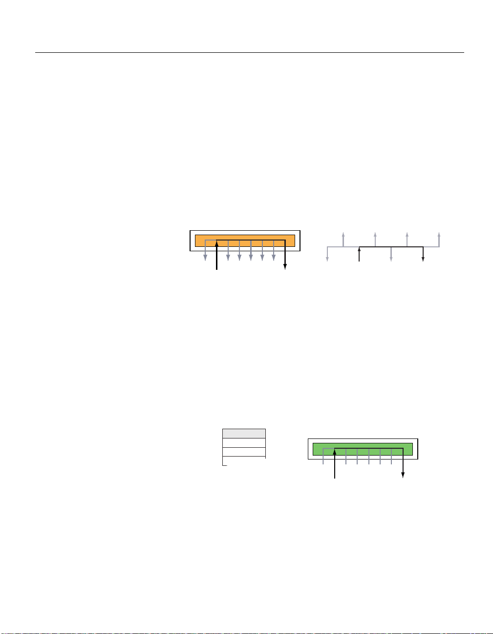
What is a Switch?
A switch segments traffic, providing each port its own collision domain. This
is different from a hub where all ports belong to the same collision domain.
Segments and Hubs
Hubs combine multiple wires so all attached devices behave like they are on
the same wire. Because the devices share the same segment, data sent by
one device is retransmitted to all devices on the same hub. This is equivalent
to having all devices connected in a bus topology as illustrated below.
Client A sends
signal to Client B
Signal sent to all ports
Client B
receives signal
Client A Client B
The disadvantage is all devices must share the total available bandwidth.
The more devices that are attached to the hub the less bandwidth for each
user. Also, network performance suffers because all devices receive traffic
and collisions from other users as the hub retransmits data across all ports.
Switches
Switches send traffic only to specific ports, rather than transmitting data
across all ports. This means that each device attached to the switch receives
fewer collisions and the entire bandwidth is available to the device.
MAC Address Port
006011FB34DB 2
00A027D36FAA 8
The signal is not
Client A sends
signal to Client B
The switch maintains a table that associates a device’s MAC address to a
port on the switch. When Client A communicates with Client B, the switch
checks the table to determine which port Client B is attached to and then
forwards the traffic to that port. If a device sends traffic to an address that is
not in the table (or sends broadcast or multicast traffic) the switch sends the
traffic out to all ports on the switch. When the switch receives a response it
updates the table with the new address.
sent to all ports
Client B
receives signal
12
Page 19
CHAPTER 2
Using the Intel Express 460T Standalone Switch
Sample Configurations
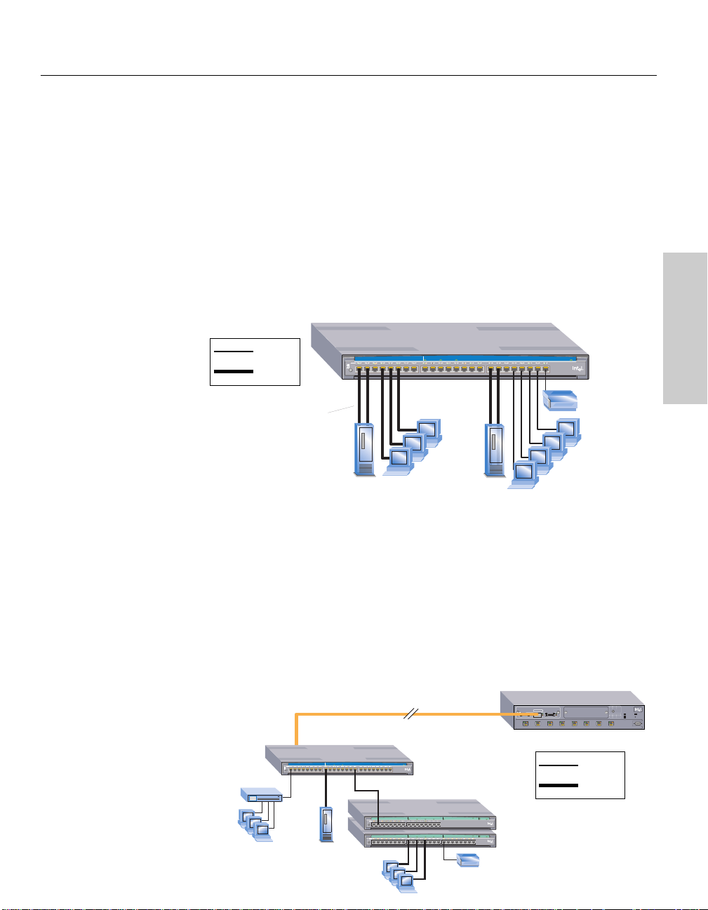
The following examples illustrate how the 460T switch can be used in a
network.
Desktop PC Bandwidth
In this example, desktop PC users are connected directly to the 460T switch.
Power users are connected at 100 Mbps while regular users can be
connected at 10 Mbps. Aggregated links provide additional bandwidth to
the servers.
10 Mbps
100 Mbps
Aggregated
link provides
bandwidth to
server
Intel® Express 460T Standalone Switch
MDI
12345678
MDI-X
Module A
Port 1 Port 2
Link\Act\Coll
Link\Act\Coll
Status
910111213141516 1718192021222324
Power users
connected at
100Mbps
Left
Link = Solid Green
Activity = Blinking Green
Collision = Blinking Orange
Right
10Mbps = Solid Orange
100Mbps = Off
Status
10Mbps
devices
Using the 460T
Small Office Backbone
In this example, the 460T switch serves as the backbone for a small network.
The switch can provide high-bandwidth support to the clients (servers and
power users) that require it while providing connections for 10 Mbps
devices. Use the optional modules available for the 460T to extend the reach
of the network beyond 100 meters (330 feet). For example, to connect
different buildings or remote campuses to an Intel® Express 550T Switch
located at a central office.
Two switches connected using 1000SX modules. The
maximum distance is 550m using multimode fiber.
Express 460T Standalone Switch
Module A
Intel® Express 460T Standalone Switch
MDI
12345678
MDI-X
10
Port 1 Port 2
Link\Act\Coll
Link\Act\Coll
Status
910111213141516 1718192021222324
Intel® Express 330T Stackable Hub
MDI /
MDI-X
Intel® Express 330T Stackable Hub
MDI /
MDI-X
Left
Link = Solid Green
Activity = Blinking Green
Collision = Blinking Orange
Right
10Mbps = Solid Orange
100Mbps = Off
Status
Module A Module B
Module A Module B
Collisions
Collisions
Express 550T Switch
1000LX Module for 500 Series Switches
CLASS 1 LASER PRODUCT
1000Base-LX
TX RX
12345678
Slot BSlot A
Stack Interface Module
10Mbps
100Mbps
LEDs Green Orange
Off
10 Mbps
Half duplex
Intel Express
Solid
100 Mbps
Full duplex
550T Routing
Port Status
Switch
Power
Status
LEDs Green Orange
Temperature
Solid
Link
Disabled
Reset
Blink
Activity
Collision
RPS
Console
9600-8-N-1
13
Page 20
CHAPTER 2
Intel Express 460T Standalone Switch Users Guide
Flow Control
When network traffic is heavy, the switch’s port buffers fill up faster than
the switch can send the information. In cases like this, the switch tells the
transmitting device to wait until the information in the buffer can be sent.
This traffic control mechanism is called flow control.
The method of flow control depends on whether the port is set to full-duplex
or half-duplex. If a port operates at half-duplex, the switch sends a collision
(also called backpressure) which causes the transmitting device to wait. If
the port operates at full-duplex, the switch sends out an IEEE 802.3x PAUSE
frame. You can enable or disable flow control for each port on the 460T
switch.
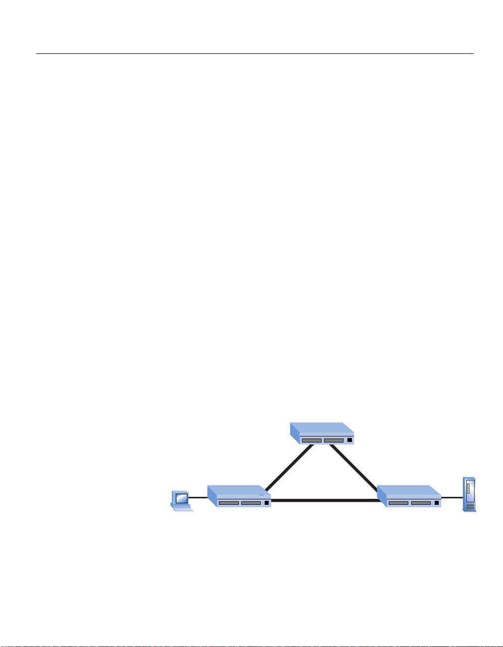
Spanning Tree Protocol
Spanning Tree is a protocol that prevents loops within the network
topology. A loop can occur if there is more than one path for information to
travel between devices. The Spanning Tree Protocol works by determining
the “cost” of a connection. For example, if two devices are connected by two
links, Spanning Tree uses the connection with the lowest cost and blocks
the second connection.
14
Spanning Tree prevents loops by allowing only one active path between any
two network devices at a time. However, you can also use this behavior to
establish redundant links between devices that can take over if the primary
link fails.
Switch B
Backup Path from Client A to Server B:
Switch A –> Switch B –> Switch C
Switch A
Primary Path from Client A to Server B: Switch A –> Switch C
Path: 3
Cost: 100
Path: 1
Cost: 100
Path: 2
Cost: 200
Switch C
Server BPC Client A
In this example, Client A can communicate with Server B over two different
paths. The primary path is Path 1 because the cost of the connection
between switches A and C is lower than the cost between switches A, B and
C. If the primary path fails, then traffic is automatically sent over the backup
path.
Page 21
CHAPTER 2
Using the Intel Express 460T Standalone Switch
Tagged Frames
The 802.1D (1998 Edition) and 802.1Q specifications published by the IEEE
(Institute of Electrical and Electronic Engineers) extended Ethernet
functionality to add tag information to Ethernet frames and propagate these
tagged frames between bridges (for example, a switch). The tag can carry
priority information, VLAN information, or both and enables bridges to
intelligently direct traffic across the network.
Using the 460T
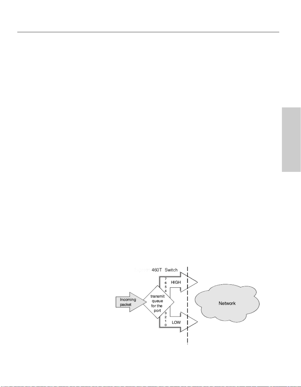
Priority
The IEEE 802.1D (1998 Edition) specification incorporates IEEE 802.1p and
defines information in the frame tag to indicate a priority level. When these
tagged packets are sent out on the network, the higher priority packets are
transferred first. Priority packet tagging (also known as Traffic Class
Expediting) is usually set on the LAN adapter in a PC and works with other
elements of the network (switches, routers) to deliver priority packets first.
The priority level can range from 0 (low) to 7 (high).
The 460T switch can read the priority tags and forward traffic on a per port
basis. The switch uses two priority queues per port and routes traffic to a
queue depending on the packet’s tag. For example, when a packet comes
into the switch with a high-priority tag, the switch routes the packet to its
high-priority queue.
Although there are eight priority levels, the 460T switch can only route a
packet into one of the two queues. The switch maps levels 0-3 to the low
queue (which is the default) and levels 4-7 to the high queue. If a packet is
untagged, the switch determines the best way to send the packet.
15
Page 22

CHAPTER 2
Intel Express 460T Standalone Switch Users Guide
Link Aggregation
You can use link aggregation (sometimes known as port trunking) to
combine from 2 to 8 (adjacent) ports so that they function as a single highspeed link. For example, link aggregation is useful when making connections
between switches or to connect servers to the switch.
You can also use link aggregation to increase the bandwidth to some
devices. Link aggregation can also provide a redundant link for fault
tolerance. If one link in the aggregation fails, the switch balances the traffic
among the remaining links.
2 ports aggregated x 100Mbps = 200Mbps link
4 ports aggregated x 100Mbps = 400Mbps link
16
To aggregate ports, you must link an “anchor” port to an adjacent port. The
460T Switch supports up to four link aggregation groups (anchor ports 1, 9,
17) for a 24-port switch and up to three link aggregation groups (anchor
ports 1, 9) on a 16-port switch. This includes one link aggregation group for
the two 100FX module ports.
Guidelines
When setting up link aggregation, remember these guidelines:
• The switch treats aggregated links as a single port. This includes
Spanning Tree and VLANs.
• All ports share the same settings as the anchor port. You can change
anchor port settings, but you cannot configure other ports in the link.
• When a port is configured as a member of an aggregated link, it
immediately adopts the characteristics of the anchor port. When a port
is no longer a member of an aggregated link, the characteristics are
reset to the default settings (autonegotiate speed/duplex, flow control
enabled).
• If a port is part of an aggregated link, it cannot be configured as the
target port for a port mirror. However, a port in an aggregated link can
serve as the source port for a port mirror.
Page 23
CHAPTER 2
Using the Intel Express 460T Standalone Switch
Virtual LANs (VLANs)
A Virtual LAN is a logical network grouping you can use to isolate network
traffic so members of the VLAN receive traffic only from other members.
Creating a VLAN is the equivalent of physically moving a group of devices
to a separate switch (creating a Layer 2 broadcast domain). The advantage
of a VLAN is that you can reduce broadcast traffic for the entire switch, and
increase security, without changing the wiring of your network.
The 460T switch supports three types of VLANs: port-based, MAC-based,
and tag-based. See Chapter 5 for more information about creating and
configuring VLANs.
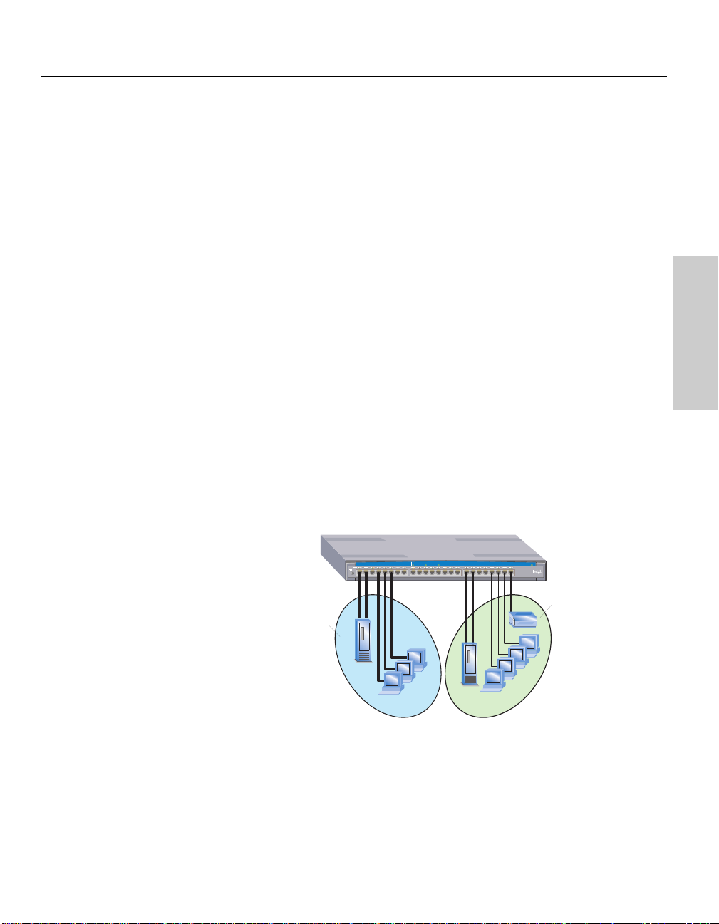
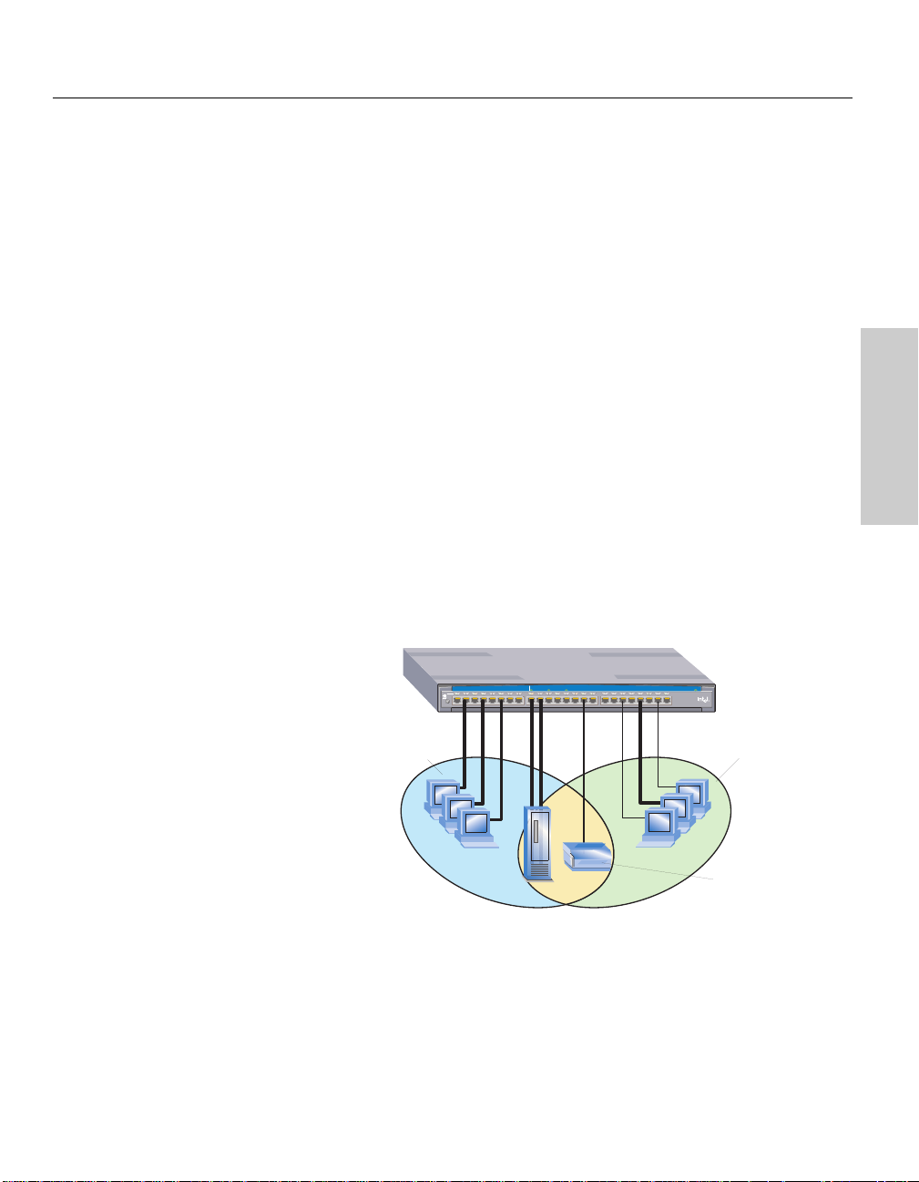
Port-Based VLANs
This is the simplest and most common form of VLAN. In a port-based
VLAN, the system administrator assigns the switch’s ports to a specific
VLAN. For example, the system administrator can designate ports 2, 4, 6,
and 9 as part of the engineering VLAN and ports 17, 19, 21, and 23 as part
of the marketing VLAN. The advantage of port-based VLANs is that they
are easy to configure and, because all changes occur at the switch, they are
transparent to the users. The 460T supports up to 12 port-based VLANs. A
port can belong to only one VLAN at a time.
Module A
These devices
are members
of VLAN 1
Intel® Express 460T Standalone Switch
MDI
12345678
MDI-X
Port 1 Port 2
Link\Act\Coll
Link\Act\Coll
Status
910111213141516 1718192021222324
Left
Link = Solid Green
Activity = Blinking Green
Collision = Blinking Orange
Right
10Mbps = Solid Orange
100Mbps = Off
Status
These devices
are members
of VLAN 2
Using the 460T
VLAN 1:
Engineering
VLAN 2:
Marketing
If a user relocates, the system administrator reassigns the port to the new
VLAN. Another advantage is if a hub is connected to a port that is part of a
VLAN, all devices connected to the hub are also part of the VLAN. The
disadvantage is that there is no way to exclude an individual device on that
hub from becoming part of the VLAN.
17
Page 24
CHAPTER 2
Intel Express 460T Standalone Switch Users Guide
MAC-Based VLANs
Membership in this type of VLAN is based on assigning the MAC address
of a device to a VLAN. The advantage to this type of VLAN is that even if
users relocate, they remain on the same VLAN as long as they stay
connected to the same switch. The 460T switch supports up to 12 MACbased VLANs.
The disadvantage is that the initial configuration and subsequent
administration of a MAC-based VLAN can be challenging because the
system administrator needs to maintain lists of MAC addresses and enter
those addresses into the switch. Another disadvantage is that MAC-based
VLANs cannot span switches.
18
MAC-based VLANs, as designed on the 460T Switch, are intended to limit
broadcast and multicast traffic over the network. The switch relies on limiting
broadcast traffic to constrain network visibility of network applications
(such as TCP/IP) that rely on broadcasts (such as ARP) for station
discovery.
The 460T MAC-based VLANs are not intended to be a secure solution. For
secure VLANs use either port-based or IEEE 802.1Q-based VLANs.
Page 25
CHAPTER 2
Using the Intel Express 460T Standalone Switch
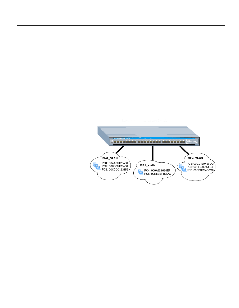
IEEE 802.1Q (Tag-Based) VLANs
The third type of VLAN supported by the 460T switch is based on the IEEE
802.1Q specification. The specification provides a uniform way to create
VLANs within a network and enables you to create a VLAN that can also
span across the network. Previously, VLAN implementation was vendorspecific so it was not possible to create a VLAN across devices from
different vendors.
The 802.1Q VLAN works by using a tag added to the Ethernet frames. The
tag contains a VLAN Identifier (VID) that identifies the frame as belonging
to a specific VLAN. These tags allow switches that support the 802.1Q
specification to segregate traffic between devices and communicate a
device’s VLAN association across switches.
There are multiple advantages to implementing 802.1Q VLANs. First, it
improves performance by helping to contain broadcast and multicast traffic
across the switch. Second, ports can belong to more than one VLAN. Third,
VLANs can span multiple switches that support the 802.1Q specification.
Finally, it provides security and improves performance by logically isolating
users and grouping them together. The 460T switch supports up to 256 tagbased VLANs.
Module A
VLAN 1:
Engineering
VLAN 1 computers
can't see VLAN 2
computers
Intel® Express 460T Standalone Switch
MDI
12345678
MDI-X
Port 1 Port 2
Link\Act\Coll
Link\Act\Coll
Status
910111213141516 1718192021222324
Status
Left
Link = Solid Green
Activity = Blinking Green
Collision = Blinking Orange
Right
10Mbps = Solid Orange
100Mbps = Off
VLAN 2:
Manufacturing
Server and printer
are members of both
VLANs
Using the 460T
A logical grouping can be mapped to a work group. For example, you can
create a VLAN that groups all the users from the engineering department
into one VLAN. This logical grouping improves performance by cutting
down traffic that belongs to a different logical group (for example,
marketing), improves security (engineering can’t see marketing), and eases
moves because the user doesn’t have to be physically located in the same
group to participate in the VLAN.
19
Page 26
CHAPTER 2
Intel Express 460T Standalone Switch Users Guide
On the 460T switch, overlapping VLANs can be supported by using 802.1Qcapable devices. However, for non-802.1Q-capable devices, overlapping
VLANs can be supported by implementing an asymmetric VLAN on the
switch. An asymmetric VLAN is a type of 802.1Q configuration where
endstations send traffic on one VLAN and receive traffic on another VLAN.
The 460T switch supports asymmetric VLANs.
For more information about asymmetric VLANs, see http://support.intel.com
/support or see IEEE 802.1Q Specification Annex B.1.3.
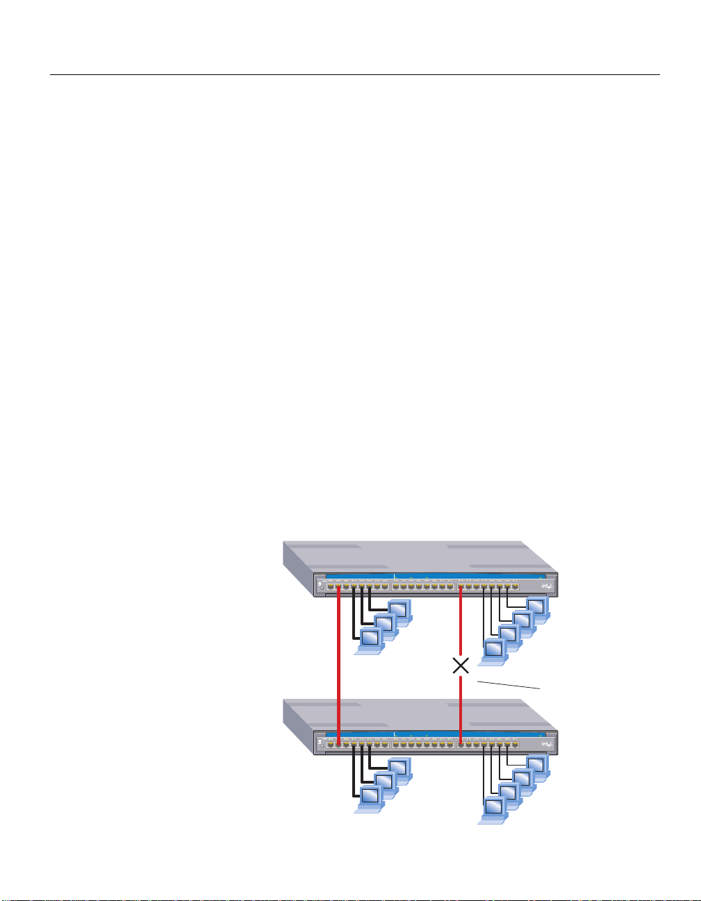
Spanning Tree and VLANs
The 460T supports the Spanning Tree Protocol across the entire switch, not
per VLAN. If a loop occurs in a VLAN the port is disabled and all VLAN
traffic over that port is blocked.
The following diagram shows an example. Both Switch 1 and Switch 2 have
two port-based VLANs configured. Crossover cables connect the
ENG_VLAN on Switch 1 to ENG_VLAN on and Switch 2. Crossover cables
also connect the MRKT_VLAN on Switch 1 to the MRKT_VLAN on Switch
2. When Spanning Tree is enabled, the redundant link between the
MRKT_VLANs is blocked and those VLANs can no longer communicate.
20
When the switch is running 802.1Q VLANs, Spanning Tree is required for
GVRP (GARP VLAN Registration Protocol) to work properly.
Module A
Switch 1
Switch 2
Intel® Express 460T Standalone Switch
MDI
12345678
MDI-X
crossover
connecting ENG_VLANs
Intel® Express 460T Standalone Switch
MDI
12345678
MDI-X
Port 1 Port 2
Link\Act\Coll
Link\Act\Coll
Status
910111213141516 1718192021222324
ENG_VLAN
ports 1-8
Module A
Port 1 Port 2
Link\Act\Coll
Link\Act\Coll
Status
910111213141516 1718192021222324
ENG_VLAN
ports 1-8
Status
Left
Link = Solid Green
Activity = Blinking Green
Collision = Blinking Orange
Right
10Mbps = Solid Orange
100Mbps = Off
MKT_VLAN
ports 17-24
Spanning Tree disables
the redundant crossover
breaking the connection
between the MKT_VLANs.
Status
Left
Link = Solid Green
Activity = Blinking Green
Collision = Blinking Orange
Right
10Mbps = Solid Orange
100Mbps = Off
MKT_VLAN
ports 17-24
Page 27

CHAPTER 2
Using the Intel Express 460T Standalone Switch
GARP VLAN Registration Protocol (GVRP)
Because IEEE 802.1Q VLANs can span networks, managing changes to the
VLAN poses a challenge for network administrators. The GARP VLAN
Registration Protocol (GVRP) provides a dynamic mechanism for switches to
share topology information and manage changes with other switches. The
network administrator does not have to manually propagate VLAN
configuration information across switches.
GARP (Generic Attribute Registration Protocol) is defined by the IEEE
802.1D (1998 Edition) specification and is the mechanism used by switches
and end nodes to propagate VLAN configurations across the network
domain. GVRP uses GARP as a foundation to propagate VLAN
configurations to other switches. Devices that support GVRP transmit their
updates to a known multicast address that all GVRP-capable devices
monitor for information updates.
Sending GVRP messages between switches accomplishes the following
tasks:
• Dynamically adds or removes a port from participating in a VLAN.
• Sends updates about the switch’s own VLAN configuration to
neighboring GVRP-capable devices.
• Integrates dynamic and static VLAN configurations within the same
switch. Static VLAN configurations are created by the user on the
switch for devices that don’t support GVRP.
Note: dynamically created VLANs are not saved in the switch’s memory.
When the device sending out the GVRP updates is disabled or rebooted, the
dynamic VLAN is removed.
Using the 460T
21
Page 28

CHAPTER 2
Intel Express 460T Standalone Switch Users Guide
Internet Group Multicast Protocol (IGMP)
Generally, the switch broadcasts multicast traffic to all ports. For multicast
traffic based on the TCP/IP using the IGMP protocol, the switch can
optimize the broadcasting of multicast traffic by forwarding multicast traffic
only to ports that require it.
IGMP Snooping is a feature that allows the switch to forward multicast
traffic intelligently. The switch “snoops” the IGMP query and report
messages and forwards traffic only to the ports that request the multicast
traffic. This prevents the switch from broadcasting the traffic to all ports
and possibly affecting network performance.
IGMP requires a router that detects multicast groups on its subnets and
keeps track of group membership. Note that multicasting is not connection
oriented, so data is delivered to the requesting hosts on a best-effort level
of service.
22
Page 29

Using Intel® Device
3
View
Overview
You can use Intel® Device View to manage Intel Express 460T Standalone
Switches and other supported Intel networking devices on your network.
Intel Device View provides these features:
• The ability to configure new network devices
• A graphical device manager for Intel switches, hubs, and routers
• Autodiscovery, which finds supported Intel devices on the network
• The Device Tree, which shows all the supported devices detected
on your network
• Remote Network Monitoring (RMON)
• Web or Windows* platform
• Plug-in to Hewlett Packard OpenView*, IBM Tivoli NetView*, and
Intel LANDesk® Network Manager
• Other useful tools such as a TFTP server
23
Page 30
CHAPTER 3
Intel Express 460T Standalone Switch Users Guide
Installing Intel Device View
Before you install Intel Device View, make sure your PC meets the system
requirements in the Intel Device View User Guide, which is included on the
Intel Device View CD-ROM.
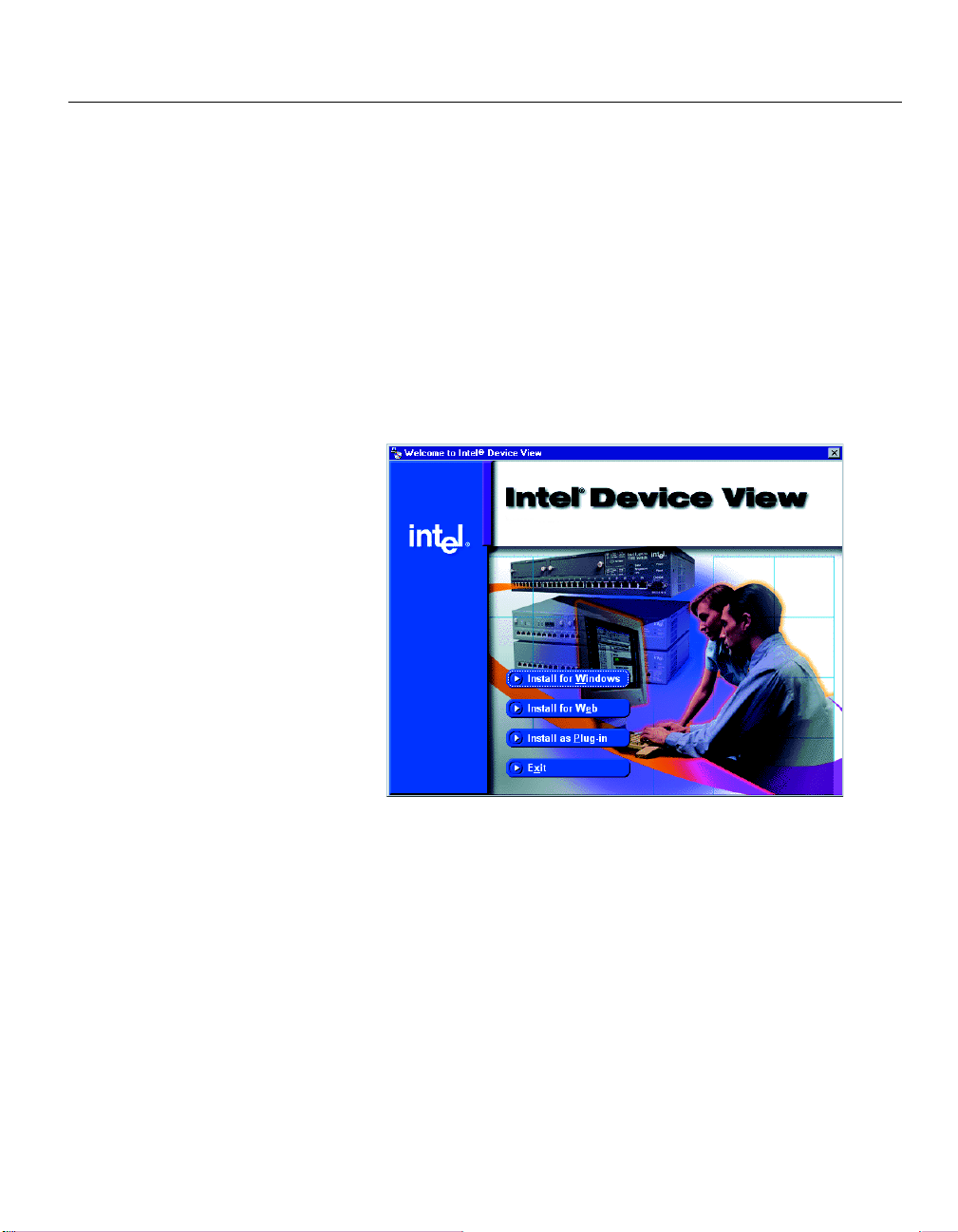
To install Intel Device View
1 Insert the Intel Device View CD-ROM in your computer’s CD-ROM
drive. The Intel Device View installation screen appears. If it doesn’t
appear, run autoplay.exe from the CD-ROM.
24
2 Choose the version of Intel Device View you want to install.
• Click Install for Windows to install Intel Device View for use on
this PC only.
• Click Install for Web to install Intel Device View on a Web
server. Access the Device View server from any PC on your
network with Microsoft Internet Explorer* 4.0x or later.
• Click Install as Plug-in to install Intel network device support for
Hewlett Packard OpenView, IBM Tivoli NetView, or Intel LANDesk
Network Manager. This option is available when you have
OpenView, Net View, or LANDesk Network Manager installed on
the PC.
3 Follow the on-screen instructions in the installation program.
Page 31

CHAPTER 3
NOTE
These are the requirements if you
want to use the Web version of
Intel Device View:
Intel Device View
Starting Intel Device View
Install either the Windows or Web version of Intel Device View.
Windows version
From your desktop, click Start and then click Programs > Intel Device View >
Intel Device View - Windows. The main screen appears.
Web version
• From your desktop, click Start and then click Programs > Intel Device
View > Intel Device View - Web. The main screen appears.
• To view Intel Device View from another PC on your network, type the
following URL.
http://servername/devview/main.htm
where servername is the IP address or name of the server where Intel
Device View is installed. The main screen appears.
Intel Device View
Web browser
Internet Explorer 4.0 or later
Web Server
IIS 2.0 or later
Peer Web Services*
Netscape Enterprise* Web
Server 3.01 or later
Installing a New Device
After you’ve installed a new switch on your network, you can use the Intel
Device View Device Install Wizard to configure it for management.
25
Page 32

CHAPTER 3
NOTE
The 460T sends BootP requests
for several minutes; after that
time, if no IP has been entered,
the switch stops sending the
request and continues to boot.
Intel Express 460T Standalone Switch Users Guide
To install and configure a new switch for
management
1 Start Intel Device View. The Device Install Wizard appears. If it doesn’t
appear, click Install from the Device menu or double-click the
appropriate MAC address in the Device Tree under Unconfigured
Devices. (The MAC address is located on the rear of the switch.)
2 On the Device Install Wizard - Start screen, click Next.
3 On the Device Install Wizard - MAC Address screen, click the MAC
address of the new switch and then click Next.
26
4 Follow the instructions in the wizard to assign an IP address and a name
to the switch.
Using the Device Tree
When you start Intel Device View, the Device Discovery service begins
searching for supported Intel network devices on your network. As it
discovers devices, the Device Discovery service adds an icon for each
device to the Device Tree on the left side of the screen.
Page 33

CHAPTER 3
Intel Device View
Different states of the 460T switch are represented by icons in the Device
Tree.
Device Tree icons
Device Tree root
Subnet
Intel Express Switch (if non-responding the icon is red)
Unconfigured Intel Express Switch
Group of Intel Express Switches
Intel Express Router
Intel Express Switch (Layer 3 capable)
Intel Express Stackable Hub
Intel Device View
The Device Tree works much like Windows Explorer. To expand the root or
a subnet, click the (+) next to the icon. To collapse the view, click the (-)
next to the icon. Double-click a device icon to view the device image.
To add a device to the Device Tree
Use this procedure if the device does not automatically appear after
installation.
1 Right-click anywhere on the Device Tree.
2 Click Add Device on the menu that appears.
3 In the Add Device dialog box, type the IP address of the switch you
want to add.
4 Fill in the other fields, as appropriate.
5 Click OK.
The icon for the new switch appears in the Device Tree.
27
Page 34

CHAPTER 3
Intel Express 460T Standalone Switch Users Guide
To refresh the Device Tree
Refreshing the Device Tree updates it to show any newly discovered
devices and changes in device status.
1 Right-click anywhere on the Device Tree.
2 Click Refresh on the menu that appears.
To delete a device from the Device Tree
1 Right-click the device you want to remove from the Device Tree.
2 Click Delete on the menu that appears.
Deleting a device from the Device Tree does not affect the actual device.
To find a device in the Device Tree
1 Right-click anywhere on the Device Tree.
2 Click Find on the menu that appears.
3 In the Find Device dialog box, type the IP address of the device you
want to find in the tree.
4 Click OK.
28
The device’s icon is highlighted in the Device Tree.
Losing contact with a device
If Intel Device View loses contact with a switch, it replaces the switch icon
with the non-responding switch icon, which is red.
If the non-responding switch icon appears, you cannot manage the device in
Intel Device View. If you cannot ping the device or start a Telnet session, try
accessing the switch’s Local Management.
Page 35

CHAPTER 3
Intel Device View
Managing a Switch
To manage an Intel Express 460T Standalone Switch, double-click the switch
icon in the Device Tree. In the example shown below, the switch has been
assigned an IP address of 124.123.122.3.
The Web Device Manager appears in the Intel Device View window.
Intel Device View
For information about using Intel Device View,see the program’s Help or
see the Intel Device View User Guide on the Intel Device View installation
CD-ROM.
29
Page 36

CHAPTER 3
Intel Express 460T Standalone Switch Users Guide
Viewing RMON information
The remote monitoring (RMON) specification extends SNMP functionality to
look at traffic patterns on the network instead of merely looking at the traffic
for an individual device. The following RMON groups are supported:
• Group 1 (S tatistics): Monitors utilization and error statistics for each
network segment (10 Mbps or 100 Mbps).
• Group 2 (History): Records periodic statistical samples from variables
available in the statistics group.
• Group 3 (Alarms): Enabless you to set a sampling interval and alarm
thresholds for statistics. When a threshold is passed, the switch creates
an event. For example, you might set an alarm to create an event if switch
utilization exceeds 30%.
• Group 9 (Events): Provides notification and tells the switch what to do
when an event occurs on the network. Events can send a trap to a
receiving station or place an entry in the log table, or both. For example,
when the switch experiences an RMON Event, it sends out an Alarm.
The switch also keeps a log that shows a list of the RMON Events and
RMON Alarms that have occurred on the switch.
30
To view RMON statistics
1 Right-click the icon for the switch in the Device Tree and then point to
RMON.
2 Click the RMON option you want to view.
T o access RMON features, you can use LANDesk Network Manager or an
SNMP application that supports RMON such as OpenV iew. For more
information about using RMON to monitor the switch, see the Intel Device
View Help.
Page 37

Using the Web
4
Device Manager
You can use the Web Device Manager, which is built into the Intel® Express
460T Standalone Switch, to manage and monitor the switch using a Web
browser. For example, you can use the Web Device Manager to configure
the switch or individual ports, or to monitor traffic statistics and utilization.
For more information about using this interface, see the Web Device
Manager Help.
31
Page 38

CHAPTER 4
Intel Express 460T Standalone Switch Users Guide
Accessing the Web Device Manager
1 In the Location or Address field of your Web browser type the IP
address of the switch. For example, to use the default IP address of the
switch, type 192.0.2.1 in the Location or Address field and then press
Enter.
Note
The default IP address assigned
to the switch is 192.0.2.1. To
access the switch with the
default IP address, your workstation must be on the 192.0.2.0
subnet.
Or you can connect to the switch
using Local Management and set
an IP address that is on your
network. Then you can access the
Web Device Manager using the
new IP address.
2 When prompted, type your user name and password. By default, no
user name or password is assigned. If you previously set a user name
and password using Local Management, enter those here.
3 Click OK. The Web Device Manager screen appears in your Web
browser.
32
Page 39

CHAPTER 4
Click a menu to view
available options.
Click a menu option to
view the corresponding
help screen.
Web Device Manager
Navigating the Web Device Manager
1 On the left side of the Web Device Manager window, click a menu item
(such as Configure Device) to show the available options.
2 Click an option on the menu. The corresponding screen appears on the
right side of your Web browser window.
3 To hide the options, click the menu item again.
Web Device Manager
33
Page 40

CHAPTER 4
Intel Express 460T Standalone Switch Users Guide
Using Management Screens
After you select an option from the navigation menu, the corresponding
screen appears in the right side of your Web browser window.
Switch faceplate graphic
A graphical representation of the switch faceplate appears at the top of the
screen. The following example shows a 24-port switch.
If the option you’re working with allows you to configure or monitor a
specific port, you can change to that port by clicking it on the faceplate
graphic.
Port color on the faceplate graphic indicates the status of the port.
Port Color Meaning
Green Port has a link at 100 Mbps.
Green with “10” Port has a link at 10 Mbps.
Magenta outline Ports are in a link aggregation.
Orange Port is disabled.
Gray No link.
34
Buttons
Each configuration screen includes four buttons on the bottom of the
screen.
Button Function
Submit Applies the configuration settings on the current screen.
Note: If you do not save the settings to the switch’s flash
memory your changes will be lost when the switch is
rebooted.
Reset Clears any changes you made on the current screen and
restores the currently applied settings.
Default Applies factory defaults for this screen’s settings. When
you log out, you can permanently save the new settings to
the switch. Otherwise, they are lost upon the next reboot.
Help Displays Help for the current screen.
Page 41

CHAPTER 4
Web Device Manager
Configuring the Switch’s IP Settings
Note: You must select Manual in the IP Assignment Method box before you
can change the IP settings.
1 Click the Configure Device menu and then click IP Settings. The IP
Settings screen appears on the right side of the Web Device Manager
window.
2 To manually configure the IP settings, select Manual in the IP
Assignment Method box. Under Change, type the new IP address,
subnet mask, and default gateway. If you have set up tag-based VLANs
on the switch, you can specify the VID of the VLAN where the switch’s
SNMP management agent will reside.
3 Click Submit.
4 The new IP settings do not take effect until the switch reboots. Do one
of the following:
To have the changes take effect now, click Save and Reboot. Rebooting
the switch temporarily interrupts network connectivity to the switch.
To have the changes take effect later, click Reboot Later.
Web Device Manager
35
Page 42

CHAPTER 4
Intel Express 460T Standalone Switch Users Guide
Configuring a Port
You can use the Web Device Manager to enable or disable a port, and to
change its speed, duplex, flow control, and priority settings.
To change port settings
1 Click the Configure Device menu and then click Port Settings. To access
the Port Settings screen, click the port you want to configure on the
faceplate graphic.
Note
If you change the flow control or
IP settings, you must reboot the
switch before the new settings
can take effect.
36
2 Click the options you want to change.
• Port State to enable or disable the port.
• Speed/Duplex to set port speed to Auto-Negotiate, 10 Mbps,
or100 Mbps.
• Flow Control to enable or disable flow control.
• Priority Queue to set the priority queue for packets
sent or received on this port.
3 Click Submit.
Page 43

CHAPTER 4
Note
The accounts and passwords you
create with the Web Device Manager are the same accounts and
passwords used to access Local
Management.
Web Device Manager
Managing User Accounts
Create user accounts to give specific users read or write access to the switch
through the Web Device Manager and Local Management. You can create
up to three accounts on the switch.
To create a user account
1 Click the Configure Management menu and then click User Accounts.
The first account you create must be an administrator.
2 Click Add.
3 In the User Name box, type a username. The username can be up to
fifteen characters long and is case-sensitive.
4 In the Password box, type a password. The password can be up to
fifteen characters long and is case-sensitive. Asterisks (*) appear on the
screen as you type the password.
5 In the Confirm Password box, type the same password.
6 In the Access Level box click an access level. An administrator can view
all settings and make configuration changes. A user can only view
settings and cannot change the configuration.
7 Click Submit.
37
Web Device Manager
Page 44

CHAPTER 4
Intel Express 460T Standalone Switch Users Guide
To delete a user account
1 Click the Configure Management menu and then click User Accounts.
2 In the User Accounts screen, click the account you want to delete.
3 Click Delete.
If you delete the account you used to log in for this session, you can
continue to use that account until you log out. If you delete the only user
account on the switch, you can log in again using the default of no
username and no password.
38
Page 45

CHAPTER 4
NOTE
You can have only one operation
mode active on the switch at a
time. Choose port-based, tagbased or MAC-based.
Web Device Manager
Configuring VLANs
Virtual LANs, or VLANs, provide a way to create a logical network grouping
without regard to physical location of the network nodes.
For more information about VLANs, see “Virtual LANs” in Chapter 2.
The two main steps to set up a VLAN with the Web Device Manager are:
• Set the switch’s VLAN operation mode.
• Configure the type of VLAN you selected.
To set the switch’s VLAN operation mode
1 Click the Configure VLAN menu and then click VLAN Operation Mode.
2 In the Current VLAN Mode Is box, click the type of VLAN to set up.
You can set the 460T switch to use port-based, MAC-based, or tagbased VLANs. See “Virtual LANs” in Chapter 2 for more information
about VLAN types.
3 Click Submit.
4 The switch automatically reboots. The switch must be rebooted
whenever you change its VLAN operation mode.
After the switch reboots, you can configure the type of VLAN that you
selected.
Web Device Manager
39
Page 46

CHAPTER 4
Intel Express 460T Standalone Switch Users Guide
Port-based VLAN
You configure a port-based VLAN by creating the VLAN and then adding
participating ports. The switch can support up to 12 port-based VLANs.
However a port can be a member of only one VLAN; port-based VLANs
cannot overlap.
To configure a port-based VLAN
1 Click the Configure VLAN menu and then click Port-based VLAN.
40
2 Click Add to create a new VLAN, or select a VLAN and click Edit to
change its configuration.
3 If you are creating a new VLAN, type a name in the VLAN Name box.
4 In the Available ports box, select a port to add to the VLAN and click
Add.
5 Click Submit.
Page 47

CHAPTER 4
Web Device Manager
MAC-based VLAN
You configure a MAC-based VLAN by creating the VLAN and then adding
the MAC addresses of member devices.
To create a MAC-based VLAN
1 Click the Configure VLAN menu and then click MAC-based VLAN.
2 Click Add VLAN.
3 In the VLAN Name box, type a name for the VLAN.
4 Click Submit.
To add or delete addresses from a MAC-based VLAN
1 In the list of MAC-based VLANs, click a VLAN and then click Edit
MAC Addresses.
2 In the MAC Address field, type a MAC address (without the hyphens)
and click Add. All MAC addresses in the VLAN are listed in the MAC
Addresses box.
3 To delete an address from the member list, click the address and click
Delete.
4 When the list of addresses is complete, click Submit.
Web Device Manager
41
Page 48

CHAPTER 4
Intel Express 460T Standalone Switch Users Guide
Tag-based VLAN
You configure a tag-based VLAN by configuring port membership and
ingress/egress rules. If any of your devices don’t support 802.1Q VLAN
tags, additional configuration may be necessary.
To configure a tag-based (IEEE 802.1Q) VLAN
1 Create a VLAN and assign member ports.
a Click the Configure VLAN menu and then click Tag-based (IEEE
802.1Q) VLAN.
b On the main Tag-based VLAN page, click Add to create a new VLAN.
To modify an existing VLAN, click the VLAN name and click Edit.
42
c If you are creating a new VLAN, type a name and VID (from 2 to 4094)
to identify it.
d To add a port to the VLAN, click the port in the Available ports box
and click Add. To remove a port, click the port in the Member ports
box and click Remove.
e The switch supports up to 12 IGMP Snooping sessions to manage
broadcast traffic. To make the VLAN be part of an IGMP Snooping
session, select the Enable IGMP Snooping check box.
f When you finish adding ports, click Next.
Page 49
CHAPTER 4
Web Device Manager
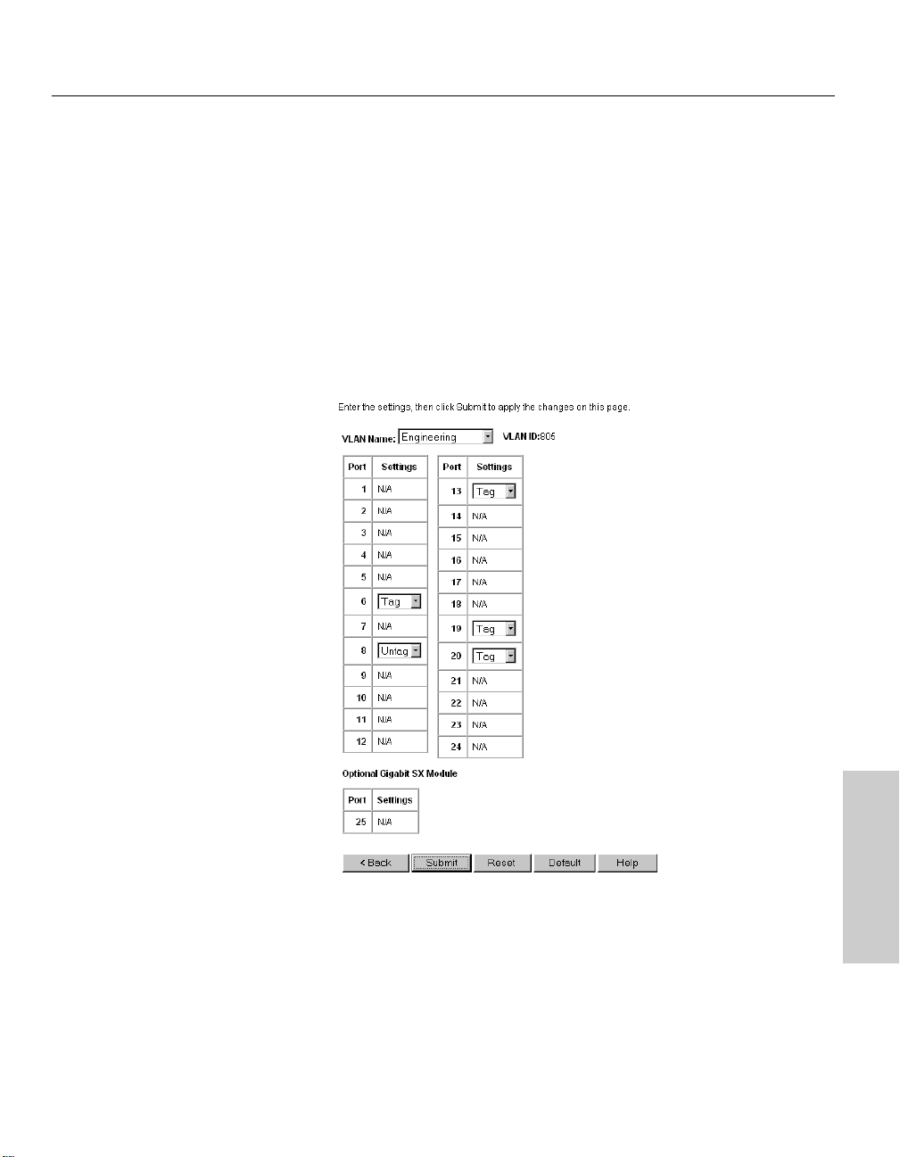
2 Configure ports for egress (outbound) tagging.
a Ensure that the VLAN Name field displays the name of the VLAN you
are configuring.
b To determine whether or not the switch will remove (untag) tags
before sending traffic out of each port, select Tag or Untag for each
of the VLAN’s ports.
c Click Submit.
Web Device Manager
43
Page 50

CHAPTER 4
Intel Express 460T Standalone Switch Users Guide
3 Configure ports for handling untagged traffic.
a From the main Tag-based VLAN page, click Port Settings.
b On the Port Settings screen, you can set port-specific behaviors for
processing VLAN traffic. To configure a specific port, click it in the
faceplate graphic. To configure the same setting across all ports, click
Configure All Ports and Module.
Options include:
44
• Default Port VID: Sets the port VID (PVID) that will be assigned to
untagged traffic on a given port. For example, if port 10's default PVID
is 100, all untagged packets on port 10 will belong to VLAN 100. The
default setting for all ports is VID 1.
• GVRP: Allows automatic VLAN configuration between the switch
and nodes.
• Ingress filtering: Allows incoming frames belonging to a specific
VLAN to be forwarded if the port belongs to the same VLAN.
Disabling this setting causes all frames to be forwarded, regardless of
the port's VLAN membership.
4 Click Submit.
Page 51
CHAPTER 4
Web Device Manager
NOTE
When configuring link aggregation
between two 460T switches, you
must connect anchor port to
anchor port, and member port to
member port.
NOTE
Connectivity is momentarily
interrupted when you apply
changes.
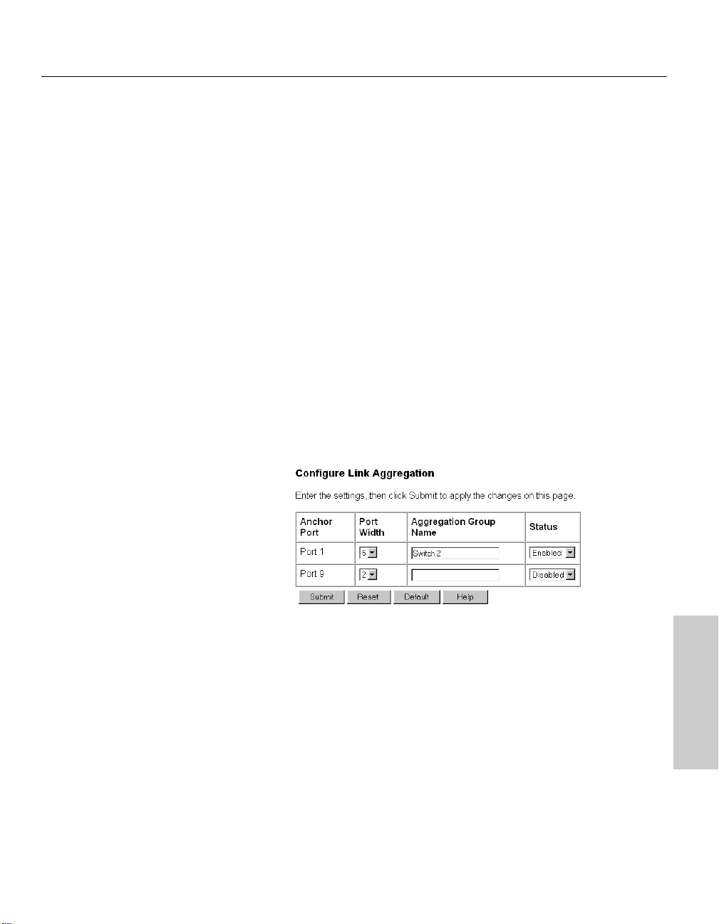
Link Aggregation
Use link aggregation to group up to eight consecutive ports into a single
dedicated connection. This feature can expand bandwidth between devices
on the network, such as another switch or a server.
The anchor port is the base port in a link aggregation, and it is the only port
in the aggregation with configurable settings. All member ports in an
aggregation take on the settings of the anchor port.
Only consecutive ports, starting from the anchor port, can be grouped in a
link aggregation. For example, ports 1, 2, and 3 are a valid link aggregation;
ports 2, 4, and 7 are not.
On the Web Device Manager switch faceplate graphic, a link aggregation is
shown with its ports outlined in magenta.
To create a link aggregation
1 Click the Configure Device menu and then click Link Aggregation.
2 Choose the anchor port. Anchor ports are listed by number in the left
column.
3 In the Port Width box, click the total number of ports (including the
anchor port) to include in the link aggregation.
4 In the Aggregation Group Name box, ype a name for the aggregation
group.
5 To make the group active, click Enable.
6 Click Submit.
Web Device Manager
45
Page 52

CHAPTER 4
Intel Express 460T Standalone Switch Users Guide
Static MAC Addresses
The MAC address table stores all the MAC addresses known by the switch.
The switch uses this table for forwarding traffic to specific devices to avoid
broadcasting traffic to every port for communication.
There are two ways to add addresses to the MAC address table:
• The switch can learn addresses and add them dynamically. Dynamic
entries remain in the table only while the associated node is active. They
are deleted if the node is inactive for longer than a specified period of
time, known as the age-out time; the default is 300 seconds.
• You can manually add MAC addresses to the table. These are called
static addresses, because they remain in the table until you remove
them, even if the associated node is inactive or taken off the network.
To add a static MAC address to the address table
1 Click the Configure Device menu, then click Forwarding and Filtering.
2 Click Static MAC Addresses.
Note
To view the switch’s address
table, click the Monitor menu,
click Advanced, then click MAC
Address Table.
46
3 Click Add.
4 In the MAC Address box, type the MAC address of a device on the
network. Do not include hyphens.
5 If port-based or tag-based (IEEE 802.1Q) VLANs are set up on the
switch, static MAC addresses are associated with specific VLANs.
Type the VLAN name (port-based VLANs) or VID (tag-based VLANs)
to associate with the MAC address.
6 In the Port number box, click a port number. The port number for the
optional LX and SX modules is MP1; the port numbers for the FX
module are MP1 and MP2.
7 Click Add.
Page 53
CHAPTER 4
NOTE
The following traps are supported
by the switch:
• Power to the switch was
cycled or reset.
• Link, speed, or other status
changes on a port.
• A port is partitioned.
• Authentication failure.
Web Device Manager
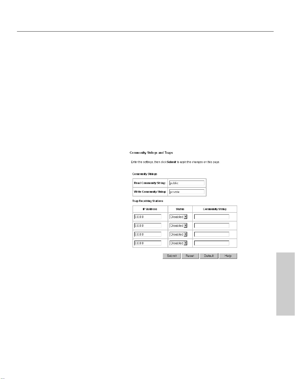
Configuring Community Strings and
Trap Receivers
A trap receiver is a computer on the network that is running an SNMP
management application and receives messages sent by the switch. For
example, the switch can send a trap to the trap receiver when it detects a
change in port speed.
To specify a trap receiver
1 Click the Configure Management menu and then click Community
Strings and Traps.
2 In the IP Address box, type the IP address of the computer you want to
use as a trap receiver. You can specify up to four trap receivers.
3 In the Status box, click Enabled.
4 In the Community String box, type the trap receiver’s SNMP application
community string.
5 Click Submit.
Web Device Manager
47
Page 54

CHAPTER 4
Intel Express 460T Standalone Switch Users Guide
Monitoring Switch Activity
The Web Device Manager lets you view traffic, utilization, and error
statistics for the switch and for individual ports. For more information on
statistics, see “Port Traffic Statistics,” “Port Error Statistics,” and “Packet
Analysis” in Chapter 5.
To view port statistics
1 Click the Monitor menu and then click Port Statistics.
2 From the row of options under the page heading, click the option you
want to view:
• Traffic
• Utilization Graph
• Errors
• Packet Analysis
48
Page 55

CHAPTER 4
Web Device Manager
Viewing/Changing Switch Information
You can view information about the switch, such as its MAC address,
firmware version, name, location, and contact person. Some of the fields can
be updated, others are read-only.
To view and configure switch settings
1 Click the Configure Device menu and then click Switch Settings.
2 In the Switch Name, Location, and Contact fields you can provide
additional information about the switch. You can type up to 40
characters in each field.
3 When you finish, click Submit.
Web Device Manager
49
Page 56

CHAPTER 4
Intel Express 460T Standalone Switch Users Guide
Updating Switch Firmware
Use the Update Firmware screen to set the switch up to update its firmware
from a TFTP server. The actual firmware update occurs while the switch is
rebooting.
To update the switch’s firmware
1 Click the Reset and Update menu and then click Update Firmware.
Note
If you don’t have a TFTP server
application, one is provided with
Intel Device View (for Windows*)
and LANDesk® Network Manager.
50
2 In the Update Mode box, select a mode:
• If the switch will use a network connection for downloading the
new firmware file, click Network.
• If the switch will use a SLIP out-of-band connection (for example, a
serial port) for downloading the new firmware file, click SLIP .
3 In the TFTP Server Address box, type the IP address of the server that
hosts the file.
4 In the Firmware Update box, click Enabled.
5 In the File Name box, type the name of the firmware file.
6 Click Submit.
The next time the switch reboots it downloads and installs the new firmware
during the boot process. If you want to view this process, you must use a
terminal program and be connected to the switch though the console port.
Page 57
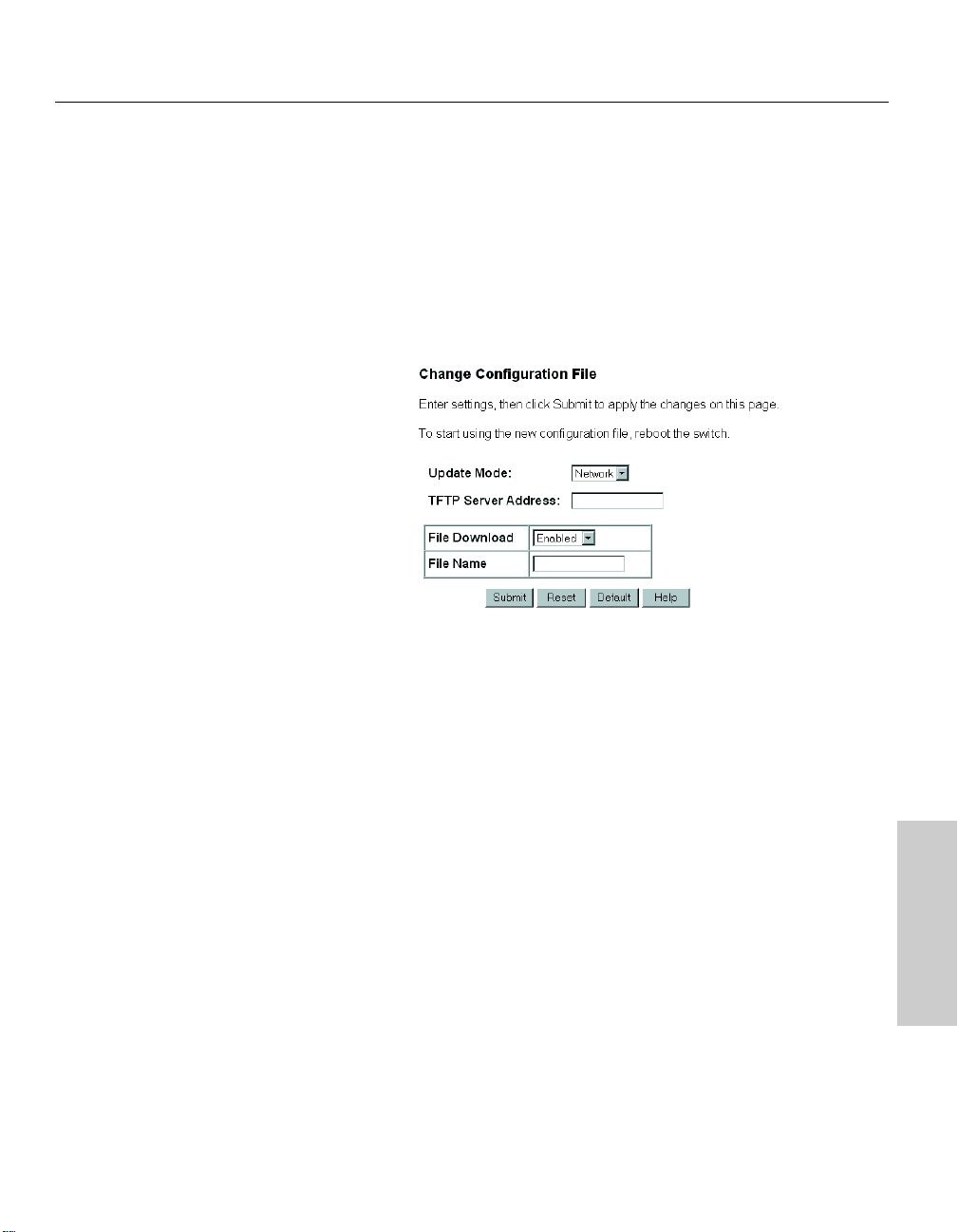
CHAPTER 4
Web Device Manager
To update the switch’s configuration file
The configuration file contains information and configuration settings
specified by the network administrator. For more information on using
configuration files, see “Upload Configuration Image File” in Chapter 5.
1 Click the Reset and Update menu and then click Change Configuration
File.
2 Select a mode from the Update Mode box.
• If the switch will use a network connection for downloading the
new configuration file, click Network.
• If the switch will use a SLIP out-of-band connection (for example, a
serial port) for downloading the new configuration file, click SLIP .
3 In the TFTP Server Address box, type the IP address of the server that
hosts the file.
4 In the File Download box, click Enabled.
5 In the File Name box, type the name of the configuration file.
6 Click Submit.
The new configuration settings will be applied to the switch upon the next
reboot.
Web Device Manager
51
Page 58

CHAPTER 4
Intel Express 460T Standalone Switch Users Guide
Saving Configuration Changes and
Logging Out
Each time you make configuration changes using the Web Device Manager,
the switch immediately uses the new settings.
However, unless you permanently save the configuration changes when
you log out of the Web Device Manager, they are lost upon the next switch
reboot.
To save changes and log out
1 On the menu, click Log Out.
52
2 Click Save Now to save the current configuration settings. The Web
browser window closes and you are successfully logged off of the Web
Device Manager.
If you click Do Not Save, all current configuration settings are lost the
next time the switch is rebooted.
Page 59

Using Local
5
NOTE
You use the same user name and
password to log onto Web Device
Manager and Local Management.
Management
Overview
Another way to configure the switch is through the Local Management
interface. Local Management provides the same functionality as the Web
Device Manager using a text-based interface.
Accessing Local Management
You can access Local Management in two different ways: by connecting
directly to the switch’s serial port, or through a Telnet session (using either
an IP address you assign or the default IP address of 192.0.2.1).
Using the serial port
1 Use the null modem cable included with the switch to connect the serial
port of your PC to the serial port of the switch.
2 Start a terminal emulation program (such as HyperTerminal* in
Windows* 98). Use these communication parameters:
• 9600 baud • 1 stop bit
• 8 data bits • No flow control
• No parity
3 Press E to connect to the Local Management.
4 Log on to Local Management. By default, no password or username is
assigned. To assign them, see “User Accounts” in this chapter.
53
Page 60

CHAPTER 5
NOTE
To access the switch using Telnet,
your workstation must be in the
same subnet as the switch.
Intel Express 460T Standalone Switch Users Guide
Using Telnet
1 Open a Telnet application. In Windows 98 or Windows NT*, select Run
from the Start Menu and then type: telnet E.
2 On the Terminal menu, select Preferences. Make sure the emulation type
is VT-100/ANSI and that VT100 arrows are enabled.
3 On the Connect menu, select Remote System. Enter the IP address of
the switch and click Connect. (The default IP address is 192.0.2.1.)
4 Log on to Local Management. By default, no password or username is
assigned.
Logon Screen
54
Description
By default, no username or password is assigned to the switch. Press
E twice to log on to the Local Manager. Usernames and passwords
can consist of any characters and can be up to fifteen characters in length.
Remember that usernames and passwords are case-sensitive.
Page 61

CHAPTER 5
Help at the bottom of the
screen provides information about the selected
item.
Using Local Management
Local Management
Navigation
The console menus provide a basic interface for configuring switch options.
For navigation tips, see the text below the graphic.
NOTE
If you are using the Windows*
2000 operating system, the arrow
keys and F1 key do not work. Use
the T and b keys to move
from field to field on the screen.
Screen Legend
Use the W Z A S keys or the T and b keys to move between
screen fields.
<Manual> Angle brackets indicate a toggle field. Use the
z to toggle selections within the field. In this
example, the options change between Manual,
BOOTP 10 Mins, BOOTP Continuous, and DHCP.
[255.255.255.0] Brackets indicate an input field.Use the arrow keys to
select the field and then type the required information.
By default, Local Management is in overstrike mode,
which means it replaces existing characters as you
type.
SUBMIT Any word in all caps is a button. Use the T key or
the W Z A S keys to select it and press E to
activate it.
55
Page 62

CHAPTER 5
LOCATION
To return to the Main Menu at any
time, press c T.
Intel Express 460T Standalone Switch Users Guide
Main Menu (Top Screen)
Description
The Main Menu is the starting point for all other Local Management
screens. Use the W Z arrow keys to choose an option and press E to
display the screen.
56
Configure device: Access menus to assign an IP address to the switch,
change port settings, or configure advanced switch settings.
Configure management: Set SNMP traps and trap monitoring stations,
administer user accounts, or update the switch’s firmware.
Configure VLAN: Set up and administer VLANs on the switch.
Monitoring: Access menus to monitor traffic and activity at the port or
switch level. These menus also provide information on network errors and
collisions.
Tools: View the switch Trap/Event log, ping devices to check connectivity,
save the current switch configuration to an image file on a server.
SAVE SETTINGS: Save configuration changes to the switch’s flash
memory. Any changes not saved to memory are lost on the next reboot.
LOGOUT: Return to the logon screen.
Page 63

CHAPTER 5
LOCATION
Main Menu
Configure Device
Using Local Management
Local Management
Configure Device
Description
IP settings: Configures the switch’s IP address.
Port settings: Configures port speed, enables and disables ports, and
displays link status.
Module port settings: Configures the module’s speed and duplex settings,
enables and disables ports, and displays link status.
Switch settings: Sets switch identification, displays detailed information
about the switch hardware and firmware, and configures some advanced
switch settings.
Spanning Tree Protocol: Configures Spanning Tree for the entire switch
or individual ports.
Forwarding and Filtering: Adds, removes, or locks the switch’s address
table, enables IGMP snooping, and sets filters for specific MAC addresses.
Port Mirroring: Sends a copy of data from one port to another for
monitoring and troubleshooting purposes.
Link Aggregation: Combines ports on the switch to increase bandwidth.
Broadcast Storm Control: Configures ports to drop excessive broadcast
traffic before it floods the network.
57
Page 64

CHAPTER 5
LOCATION
Main Menu
Configure Device
IP Settings
NOTE
The default IP address for the
switch is 192.0.2.1
Default VLAN for SNMP agent:
Port-based:DEFAULT_VLAN
802.1Q-based: VID=1
Intel Express 460T Standalone Switch Users Guide
Configure IP Address
Description
Switch MAC address: The unique hardware address assigned by Intel.
Current settings: The switch’s current IP configuration.
New settings: Assign a new IP configuration to the switch.
Assign IP: Indicates if the switch obtains an IP address dynamically, or
if you assign an address manually. The options are BOOTP 10 Mins,
which looks for a BOOTP server for 10 minutes; BOOTP Continuous;
DHCP, which looks for a DHCP server; and Manual.
IP address: The IP configuration used by the switch. Use the IP
address shown here to access the switch through Telnet or a ping test.
Subnet mask: Should match the mask for other devices on the network.
Default gateway: The IP address of the device that routes to different
networks—typically, a router or routing server. Set this option to
manage the switch remotely.
VLAN or VLAN ID (port-based or tag-based VLANs only): Specify a
VLAN where the switch’s SNMP management agent will reside. This
option appears only when port-based and IEEE 802.1Q VLANs are
active on the switch.
58
SUBMIT: Submits the changes and returns you to the Configure Device
screen. You must save the changes to the switch’s flash memory and reboot
the switch for the new IP settings to take effect.
Page 65
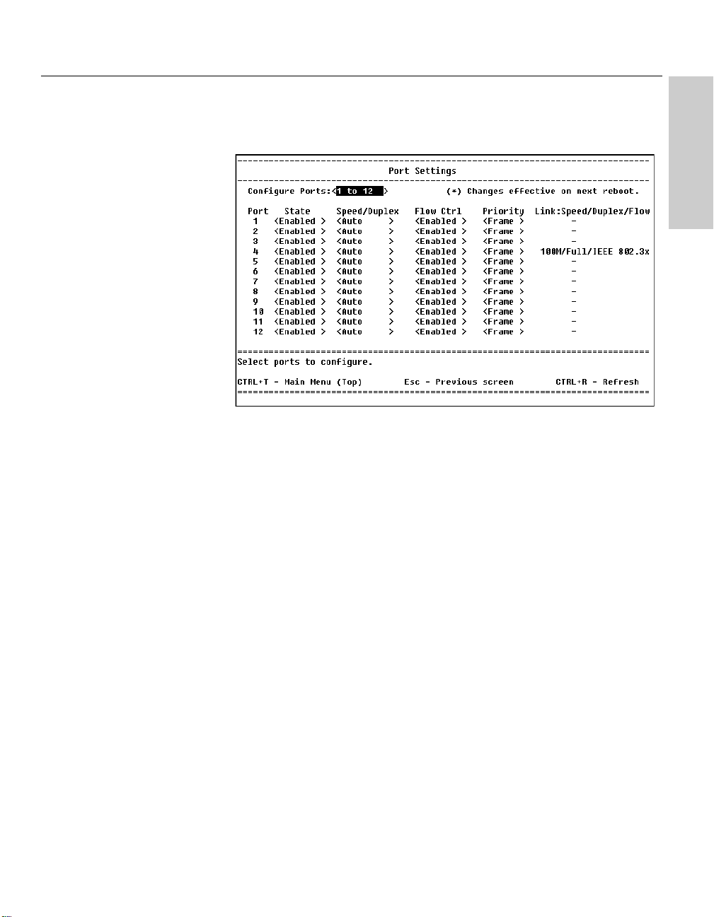
CHAPTER 5
LOCATION
Main Menu
Configure Device
Port Settings
Using Local Management
Local Management
Port Configuration
Description
Configure ports: Press the z to select a range of ports to configure.
State: Press the z to toggle the field and disable or enable ports.
Speed/Duplex: Press the z to toggle the field options and change the
speed and duplex of the port. You can set the port to auto-negotiate speed,
or to 10 Mbps or 100 Mbps at half-duplex or full-duplex.
Flow Ctrl (Control): Press the z to enable or disable flow control.
Priority: Press the z to change the settings. The <Frame> setting
reads the packet’s 802.1p priority tag and handles it accordingly. The
<Low> and <High > settings force the packet into one of two priority
queues. Forcing a packet into a queue does not retag the packet.
Link: Indicates the port’s current link status:
--: Indicates there is no device link or the port is disabled.
10M/100M: Indicates the port’s speed, either 10 Mbps or 100 Mbps.
Full/Half: Indicates a device is connected at full-duplex or half-duplex.
IEEE/BackP: Indicates the type of flow control, either IEEE PAUSE
frames or backpressure.
Partitioned: Indicates port was disabled due to a partition error.
Source mirror/Target mirror: Indicates the port being mirrored and
where the data is being sent.
59
Page 66

CHAPTER 5
LOCATION
Main Menu
Configure Device
Module Port Settings
Intel Express 460T Standalone Switch Users Guide
Module Port Settings
Description
Ports: Press the z to select a port on the module (FX Module only).
State: Press the z to toggle the field and disable or enable ports.
Speed/Duplex: Press the z to toggle the field options and change
the speed and duplex of the port. You can set the port to auto-negotiate
speed or set it to 100 Mbps at half-duplex or full-duplex (FX Module only).
60
Flow Ctrl (Control): Press the z to enable or disable flow control.
Priority: Press the z to change the settings. The <Frame> setting
reads the packet’s 802.1 priority tag and handles it accordingly. The
<Low> and <High > settings force the packet into one of two priority
queues. Forcing a packet into a queue does not retag the packet.
Link: Indicates the port’s current link status:
--: Indicates there is no device link or that the port is disabled.
10M/100M: Indicates the port’s speed, either 10 Mbps or 100 Mbps.
Full/Half: Indicates a device is connected at full-duplex or half-duplex.
IEEE/BackP: Indicates the type of flow control, either IEEE PAUSE
frames or backpressure.
Partitioned: Indicates port was disabled due to a partition error.
Source mirror/Target mirror: Indicates the port being mirrored and
where the data is being sent.
Page 67

CHAPTER 5
LOCATION
Main Menu
Configure Device
Switch Settings
Using Local Management
Local Management
Switch Settings
Description
Name: Assigns a name to the switch, up to 40 characters long.
Location: Assigns a location to the switch, up to 40 characters long.
Contact: Assigns a contact person or phone number to the switch, up to 40
characters long.
NOTE
It’s a good idea to write down
both the firmware version and
Boot PROM version, in case you
need to contact Intel Customer
Support.
Device Type: Displays the manufacturer-assigned type of switch.
Module A: Displays any module and its type installed in the switch.
MAC address: The unique hardware address assigned by Intel.
Boot PROM version: Displays the version of the switch’s boot code.
Firmware version: The version of the firmware installed on the switch.
You can update this software on the Update Firmware and Configuration
Files screen.
Serial Number: Displays the hardware serial number for the switch.
Hardware revision: Displays the version of the switch’s printed circuit
board.
CONFIGURE ADVANCED SETTINGS: Sets advanced switch settings like
port auto-partition and Head of Line blocking.
61
Page 68

CHAPTER 5
LOCATION
Main Menu
Configure Device
Switch Settings
Advanced Switch Settings
Intel Express 460T Standalone Switch Users Guide
Configure Advanced Switch Settings
Description
Auto-partition capability on all ports: If this option is enabled, the switch
partitions the port when more than 61 consecutive collisions occur while
receiving data. The first time the switch receives a good packet it
unpartitions the port. If a port is partitioned the switch can transmit data
over this port, but cannot receive data.
62
Head of Line (HOL) Blocking Prevention: If this option is enabled it
prevents the forwarding of data to a port that is blocked. Normally, when
the switch sends traffic to a port it goes to the port’s transmit queue and is
sent out. If the port’s transmit queue is already busy trying to send out
data, the switch places the waiting traffic in the buffer memory until the port
is ready to send it out.
However, if the port’s transmit queue remains full, the switch fills up more
of the buffer with traffic waiting to be sent on that port. HOL blocking
assumes that it is better to drop the traffic waiting in the buffer than to
continue using more memory and impacting performance across all the
ports.
High-priority packet service ratio: Determines how many high-priority
packets the switch sends before sending a low-priority packet. For example,
a ratio of 8 high:1 low means that the switch sends out eight high-priority
packets before sending out one low-priority packet.
Page 69
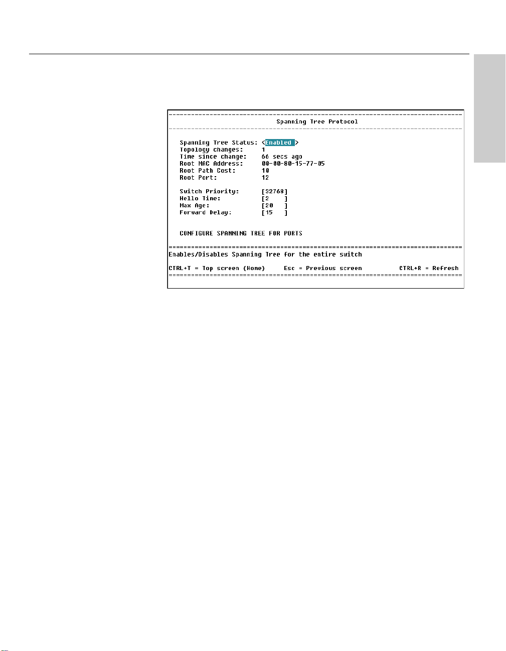
CHAPTER 5
LOCATION
Main Menu
Configure Device
Spanning Tree Protocol
Using Local Management
Local Management
Configure Spanning Tree Protocol
Description
The IEEE 802.1D Spanning Tree Protocol specification is prevents loops in a
network by allowing only one active path between any two network devices
at a time.
Spanning Tree status: Use the z to enable or disable support for the
Spanning Tree Protocol, where the entire switch is a bridge for which you
can set spanning tree parameters. (Note: If you are running 802.1Q VLANs,
spanning tree must be enabled and is turned on automatically by the
switch.)
Topology changes: The number of times the spanning tree has changed its
configuration.
Time since last change: The elapsed time (since the last switch reboot)
since the spanning tree last changed its topology (the paths used to get
through the network).
Root MAC address, Root path cost, Root port: Information used by the root
bridge in the same spanning tree as the switch.
Switch Priority: Type a number from 0 to 65535 (default is 32768). The
device with the lowest number becomes the root device (starting point for
the spanning tree).
63
Page 70

CHAPTER 5
Intel Express 460T Standalone Switch Users Guide
Hello Time: Type a number from 1 to 10 seconds (default is 2 seconds).
This is the time between transmissions of configuration BPDUs (Bridge
Protocol Data Units) when the switch is, or is attempting to become, the
root in the spanning tree.
Max Age: Type a number from 6 to 40 seconds (default is 20 seconds). This
is the maximum time that information from a configuration BPDU is used by
the switch before it is discarded.
Forward Delay: Type a number from 4 to 30 seconds (default is 15
seconds). This is the amount of time between port states when the spanning
tree is changing its status from blocking to forwarding.
CONFIGURE SPANNING TREE FOR PORTS: Takes you to the
screen where you can set spanning tree values for individual ports.
64
Page 71
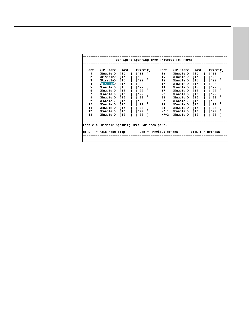
CHAPTER 5
LOCATION
Main Menu
Configure Device
Spanning Tree Protocol
Configure STP for ports
Using Local Management
Local Management
Configure Spanning Tree for Ports
Description
Port: Select the port you want to configure for spanning tree.
STP State: Use the z to enable or disable each port to be active in
the spanning tree.
Cost: Type in a number from 1 to 65535 (default is 10). This value is used
by the Spanning Tree Protocol to determine alternate routes in the network.
The higher the cost of a port, the lower the chance it will be used to forward
traffic. When possible, assign a port a low cost if it is connected to a fast
network segment.
Priority: Type in a number from 0 to 255 (default is 128) to set the port’s
priority in the spanning tree. The higher the value, the lower the chance oit
will be used as the root port. If two ports on the switch have the same
priority value, the spanning tree uses the port with the lowest number. For
example, the spanning tree would choose port 1 over port 4 if they both had
the same priority setting.
65
Page 72

CHAPTER 5
LOCATION
Main Menu
Configure Device
Forwarding and Filtering
Intel Express 460T Standalone Switch Users Guide
Forwarding and Filtering
Description
Lock address table: Use the z to toggle field values. <Yes> prevents
the switch from learning new MAC addresses. Any existing addresses the
switch has learned remain in the address table.
MAC address aging: Sets the time interval at which the switch scans its
MAC address table to determine the age of entries.
66
Configure IGMP snooping: Sets Internet Group Management Protocols
(IGMP) options for multimedia applications, such as desktop video
conferencing, that use IP multicast addresses.
Configure static MAC addresses: Allows permanent mapping between a
network device and a port.
Configure port security: Configures the switch to only allow the
transmission of authorized traffic over a particular port.
Configure MAC address filtering: Allows the switch to drop traffic from
a specific source.
Configure Ethernet multicast filtering: Blocks or forwards traffic over
each port for Ethernet (MAC-based) multicast groups.
Page 73
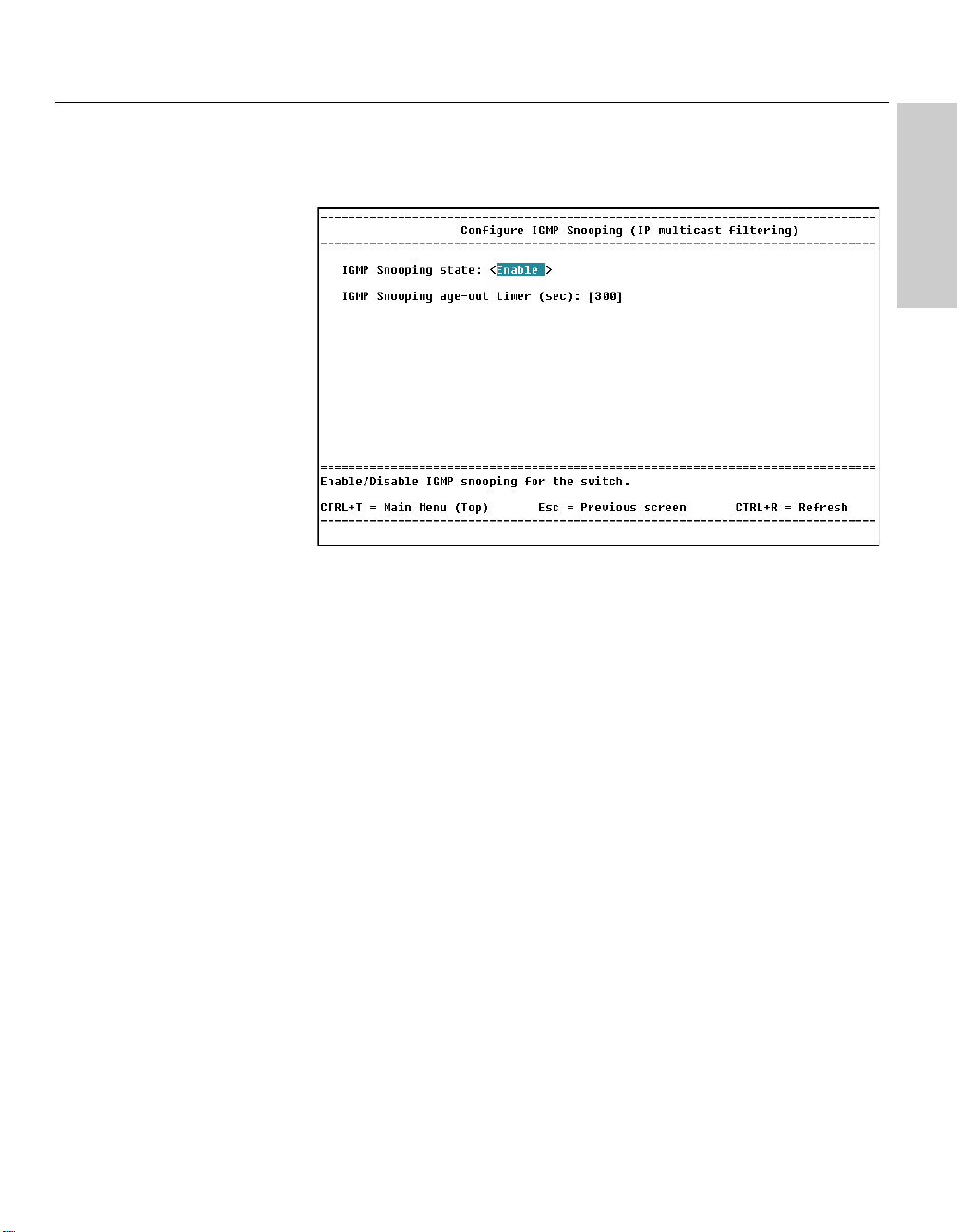
CHAPTER 5
LOCATION
Main Menu
Configure Device
Forwarding and Filtering
IGMP Snooping
Using Local Management
Local Management
Configure IGMP Snooping
Description
IGMP Snooping (Internet Group Management Protocol) allows the switch
to forward multicast traffic intelligently. The switch “snoops” the IGMP
query and report messages and forwards traffic only to the ports that
request the multicast traffic. This prevents the switch from broadcasting the
traffic to all ports and possibly affecting network performance.
NOTE
If tag-based (IEEE 802.1Q) or portbased VLANs are currently running, you must enable IGMP
snooping for each VLAN. The
switch supports up to 12 VLAN
IGMP snooping sessions.
IGMP requires a router that learns about the presence of multicast groups
on its subnets and keeps track of group membership. Remember that
multicasting is not connection oriented, so data is delivered to the
requesting hosts on a best-effort level of service.
VLAN Name (port-based or tag-based VLANs only): The VLAN for which
IGMP snooping is enabled. You can also enable IGMP snooping for a
VLAN in the Configure VLAN screen.
IGMP Snooping state: Use the z to enable or disable IGMP
Snooping.
IGMP Snooping age-out timer: Specify the acceptable time (in seconds)
between IGMP queries, starting when the switch last received an IGMP
query from the multicast server. The default time is 300 seconds. A query
allows the server to determine which network hosts are (or want to be) part
of the IP multicast group, and are configured and ready to receive traffic for
the given application.
67
Page 74

CHAPTER 5
LOCATION
Main Menu
Configure Device
Forwarding and Filtering
Static MAC Addresses
Intel Express 460T Standalone Switch Users Guide
Configure Static MAC Addresses
Description
Static MAC addresses remain in the switch’s address table, whether or not
the device is physically connected to the switch. After you define a static
MAC address, it remains in the switch’s address table until you remove it.
Enter MAC: Type the MAC address you want to add to the address table.
NOTE
If tag-based or port-based VLANs
are currently running, you must
assign each static MAC address to
a specific VLAN.
68
VLAN or VLAN ID: When VLANs are active on the switch you can define
static MAC addresses for each VLAN. If port-based VLANs are active
press the z to select a VLAN. If tag-based VLANs are active type
the VLAN ID that the static MAC address will be assigned to.
Select Port: Use the z to select a port on the switch where the
switch forwards traffic.
ADD/DELETE: Adds or removes a MAC address from the switch’s table.
Page 75

CHAPTER 5
LOCATION
Main Menu
Configure Device
Forwarding and Filtering
Configure Port Security
Using Local Management
Local Management
Configure Port Security
Description
Port security prevents unauthorized access of a port by “securing” a list of
specific MAC addresses to a port. If the switch sees a MAC address that is
not on the secured list, it discards the traffic. When port security is active,
the switch forwards traffic from a single static address automatically learned
by the switch, or from a list of static MAC addresses defined by the
administrator.
NOTE
When you set port security to
Disable, you must manually place
static MAC addresses into the
forwarding table. Only traffic from
these static MAC addresses go
through the port. Other traffic is
dropped, and the port is still
enabled.
When you set port security to
Single, the first MAC address to
hit that port is automatically
placed into the forwarding table.
Traffic from any other MAC address disabled the port.
To set port security from Local Management
1 On the Configure Device screen, select Forwarding and Filtering.
2 Select Configure Port Security from this menu.
Then choose one of the following options.
Option 1 - Automatically use the first MAC address seen on the port: The
switch remembers the first MAC address seen on the port and accepts traffic
only from that MAC address. The secured port will not learn any new MAC
addresses.
1 To set the switch to use the first MAC address seen on the port you are
securing, in the MAC Learning column, press z until <Single>
displays.
2 Click Submit.
69
Page 76

CHAPTER 5
Intel Express 460T Standalone Switch Users Guide
Option 2 - Accept a list of user-defined static MAC addresses
1 In the MAC Learning column, press z until <Disabled>
displays, to disable MAC learning for the ports you are securing.
2 Click Submit.
Then set static MAC addresses that can use the secured port.
1 Press q to move up a level and select the Configure Static MAC
Addresses screen.
2 Click Add.
3 On the Add Static MAC Addresses screen, type a MAC address
allowed to use the secured port.
4 In the Port Number box, select the port you are securing.
5 If port-based or tag-based (IEEE 802.1Q) VLANs are set up on the
switch, the address will be used by a specific VLAN. Type the name or
VID of the VLAN to use the MAC address.
6 Repeat steps 3-5 until you have added all MAC addresses allowed to
use the secured port.
7 Click Submit.
70
To turn off port security
1 On the Configure Device screen, select Forwarding and Filtering.
2 Select Configure Port Security from this menu.
3 Select the port you want to disable security on. Press the z in the
Learning field until <Enabled> appears, to disable security and allow the
port to learn new MAC addresses.
Page 77

CHAPTER 5
LOCATION
Main Menu
Configure Device
Forwarding and Filtering
MAC address Filtering
Using Local Management
Local Management
Configure MAC Address Filtering
Description
MAC address filtering enables the switch to drop unwanted traffic. The
switch drops traffic when it sees the specified MAC address in either the
source address or destination address of the incoming packet. For example, if
your network is congested because of high utilization from a specific MAC
address, you can filter all traffic transmitted from that address and restore
network flow while you troubleshoot the problem.
NOTE
If tag-based (IEEE 802.1Q) or portbased VLANs are currently running, you must assign each MAC
address filter to a specific VLAN.
Enter MAC: Type in the MAC address you want to filter.
VLAN/VLAN ID: If VLANs are active on the switch you can set MAC
address filtering for each VLAN. For port-based VLANs, press the z
to select the name of VLAN. For tag-based VLANs, type the VLAN ID for
the MAC address you want to filter.
ADD: Activates the filter and adds the MAC address to the list.
DELETE: Removes the filter for the specified MAC address.
71
Page 78

CHAPTER 5
LOCATION
Main Menu
Configure Device
Forwarding and Filtering
Ethernet Multicast Filtering
Intel Express 460T Standalone Switch Users Guide
Configure Ethernet Multicast Filtering
Description
Use Ethernet multicast filters to define which ports can receive multicast
traffic from a specific multicast MAC address. This is similar to IGMP
snooping, except you define everything manually.
VLAN/VLAN ID: If VLANs are active on the switch you can set Ethernet
Multicast filtering for each VLAN. For port-based VLANs, press the
z to select the name of VLAN. For tag-based VLANs, type the
VLAN ID for the specified multicast address.
NOTE
If tag-based (IEEE 802.1Q) or portbased VLANs are currently running, you must assign each
multicast filter to a specific VLAN.
72
Multicast address: Type the MAC address you want to apply a filter to.
ADD: Activates the filter and adds the address to the list.
DELETE: Removes the filter for the specified address.
To add or delete a multicast filter
1 In the Multicast address field, type a multicast address.
2 If the switch is running tag-based or port-based VLANs, select a VLAN
to locate the filter.
3 Select ADD using the arrow keys and press e.
4 To remove a filter, type in the MAC address in the Multicast field, select
DELETE, and press e.
Page 79

CHAPTER 5
LOCATION
Main Menu
Configure Device
Forwarding and Filtering
Ethernet Multicast Filtering
Multicast Filters Per Port
Using Local Management
Local Management
Ethernet Multicast Filtering (Ports)
Description
Action: Use the z to select whether to block or forward traffic to the
selected port.
APPLY CHANGES: Applies the changes to the multicast filter after you
have configured the ports.
To modify a multicast filter
1 On the right side of the Configure Ethernet Multicast Filter screen use
the arrow keys to select an address from the list. Press e.
2 Decide which ports should receive the multicast traffic by using the
z to set Forward or Block for each port.
3 Select APPLY CHANGES and press e. This activates the changes to
the multicast filter and returns you to the previous screen.
73
Page 80
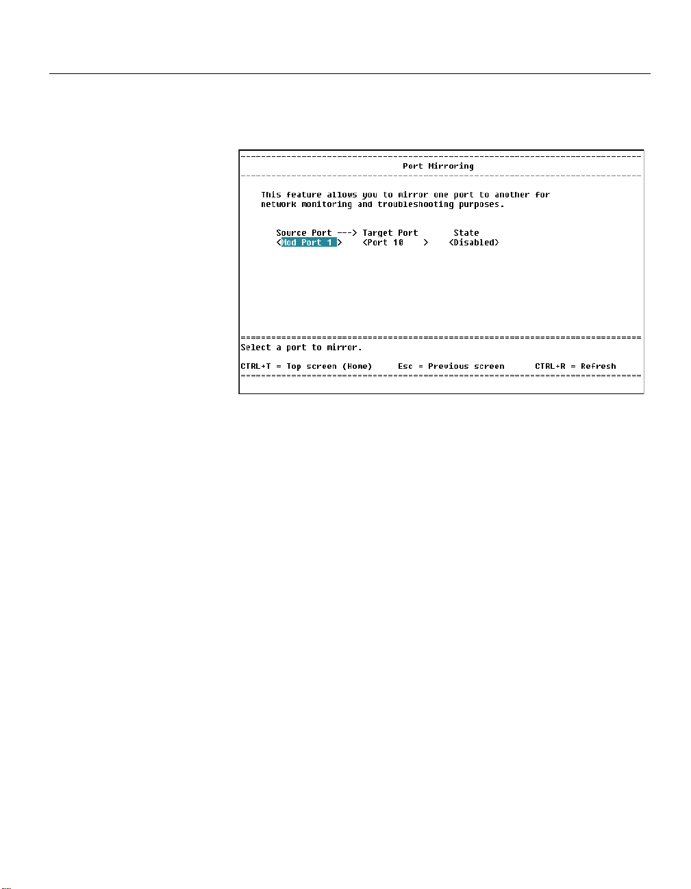
CHAPTER 5
LOCATION
Main Menu
Configure Device
Port Mirroring
NOTE
Do not mirror traffic to a target
port that is connected to network
devices other than a protocol
analyzer. Their behavior may be
unpredictable.
Intel Express 460T Standalone Switch Users Guide
Port Mirroring
Description
Port mirroring is a diagnostic tool you can use to send a copy of the good
Ethernet frames transmitted or received on one port to another port. On the
second port you can attach a protocol analyzer to capture and analyze the
data without interfering with the client on the original port.
Source Port: Use the z to select the port whose traffic you want to
mirror.
Target Port: Use the z to select a port to receive the mirrored traffic.
It is a good idea to connect a protocol analyzer to this port.
State: Use the z to enable or disable port mirror mirroring.
If a port is part of an aggregated
link, it cannot be configured as
the target port for a port mirror.
However, a port in an aggregated
link can serve as the source port
for a port mirror.
74
Page 81

CHAPTER 5
LOCATION
Main Menu
Configure Device
Link Aggregation
Using Local Management
Local Management
Link Aggregation
Description
Use link aggregation to combine ports on the switch to increase the
available bandwidth and provide redundancy. All ports in the aggregated
link take on the characteristics of the anchor port. For example, if you set
the anchor port to 100 Mbps and full duplex, all the ports aggregated to that
anchor port are 100 Mbps and full duplex.
NOTE
All custom settings for a port
(including VLAN membership) are
lost when you add that port to a
link aggregation.
Anchor Port: Shows the first port in the link aggregation.
Width: Use the z to set the total number of (consecutive) member
ports in the aggregated link. The minimum number of ports for an
aggregated link is two, and the maximum is eight, including the anchor port.
Aggregation Group Name: Assigns a name to the aggregated links for
management or identification purposes.
Status: Use the z to enable or disable the aggregated link.
75
Page 82
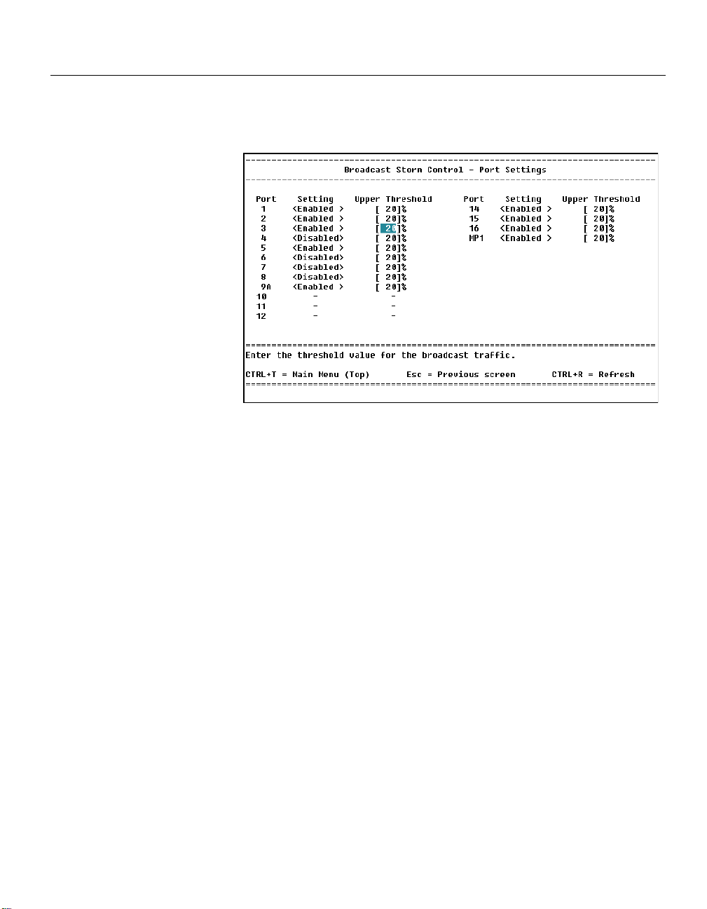
CHAPTER 5
LOCATION
Main Menu
Configure Device
Broadcast Storm Control
Intel Express 460T Standalone Switch Users Guide
Broadcast Storm Control
Description
Use this feature to filter out broadcasts from faulty devices and prevent
them from degrading network performance.
Setting: Use the z to enable or disable broadcast storm control on
this port.
76
Upper Threshold: Type a value from 1-20%. The default value is 20%. This
control lets you set the threshold of broadcast traffic on a port (shown as a
percentage of the port’s total bandwidth) that will activate broadcast storm
control. When the amount of broadcast traffic on the port exceeds the
upper threshold, the port drops all broadcast traffic. When broadcast traffic
falls below the threshold the switch automatically starts forwarding
broadcast traffic again.
Page 83
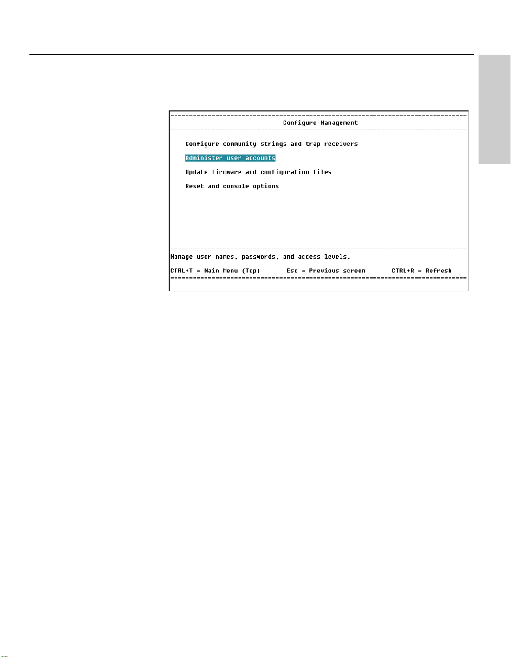
CHAPTER 5
LOCATION
Main Menu
Configure Management
Using Local Management
Local Management
Configure Management Menu
Description
Configure community strings and trap receivers: Sets the switch’s
community strings and specify trap monitoring stations.
Administer user accounts: Configures user accounts. You can add or
delete users, update passwords, and change a user’s access rights.
Update firmware and configuration files: Configures the switch’s internal
software and specifies the location of configuration files.
Reset and console options: Reboot the switch or change the settings on the
serial port. You can also set the switch back to its factory defaults.
77
Page 84

CHAPTER 5
LOCATION
Main Menu
Configure Management
Community Strings and . . .
Intel Express 460T Standalone Switch Users Guide
Community Strings & Trap Receivers
Description
Use this screen to send alerts to PCs with SNMP management applications
(such as OpenView*) installed.
Community Strings
Current read community: Sets a password for viewing (not changing)
the switch configuration. The string you define here must match the
read community string defined in an SNMP application. The default read
community string is “public.”
NOTE
These are the traps supported by
the switch:
• Power to the switch was
cycled or reset.
• Link, speed, or other status
changes on a port.
• A port is partitioned.
• Authentication failure.
• A security violation occurs on
the port.
78
Current write community: Sets a password for viewing and changing
the switch configuration. The string you define here must match the
write community string defined in an SNMP application. The default
write community string is “private.”
Trap receiving stations: When an event occurs, the switch automatically
alerts the SNMP management application by sending a trap to the SNMP
management stations (for example, PCs) defined here.
Station IP address: The IP addresses of PCs with SNMP applications
(such as Intel® Device View or LANDesk® Network Manager) installed.
State: Enables or disables sending of traps to the specified trap receiver.
Community string: Type a string for the trap that matches the
community string defined in the SNMP management application. The
default is “public.”
Page 85
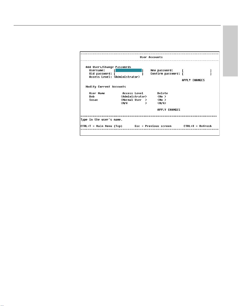
CHAPTER 5
LOCATION
Main Menu
Configure Management
Administer User Accounts
Using Local Management
Local Management
User Accounts
Description
Add Users/Change Passwords
Username: By default, no username is assigned. Usernames can
consist of any character and can be up to fifteen characters long. You
can define three usernames.
Old Password: Used when changing the password of a current user. If
this is a new account, you can skip over to the New Password field. By
default, no password is assigned.
New password: Sets a new password for accessing Local Management.
The one you specify here is used the next time you reset the switch or
log out and log in on Local Management. Passwords are case-sensitive
and can be up to fifteen characters long.
Confirm new password: Verifies the entry in the New password field.
Access Level: Use the z to determine a user’s access rights.
Administrators can make any changes to Local Management. All other
users (categorized under Normal user) can view information but cannot
make changes. To change a user’s access rights, see “Modify User
Accounts.”
APPLY CHANGES: Saves changes when adding users or changing
passwords.
79
Page 86

CHAPTER 5
Intel Express 460T Standalone Switch Users Guide
Modify User Accounts
Access Level: Use the z to change access rights for the user.
Delete: The default value is <No>. To delete an account, use the
z to change the value to <Yes>.
APPLY CHANGES: Saves changes when modifying or deleting user
accounts.
Managing User Accounts
As a system administrator, you can create up to three user accounts for
managing the switch. You can also change the access rights for current
users and delete user accounts. Make sure you always set up at least one
Administrator account.
To create a user account
1 On the Main Menu, select Configure Management. Select Administer
User Accounts and press E .
2 On the User Accounts screen, type the name of the new user in the
Username field and press E .
3 Because this is a new user, press T
and go to the New password field.
4 Type the password for the new user and press E. Passwords are
case-sensitive and can be up to fifteen characters long.
5 To confirm the new password, retype it in the Confirm new password
field. Press E .
6 Select the access rights for the new user by pressing the z .
7 To save the information, press T to select SAVE CHANGES (below
the Confirm new password field) and press E. The new account
appears in the list under Modify User Accounts.
to skip the Old password field
80
Page 87

CHAPTER 5
Using Local Management
Local Management
To change a password
1 On the Main Menu, select Configure Management and press E.
Select Administer User Accounts and press E.
2 In the Username field, type the username of the account for which you
want to change the password. Press E .
3 Type the current password in the Old password field and press
E .
4 Type the new password in the New password field and press E.
5 To confirm the password, retype it in the Confirm new password field.
Press E .
6 To save the new password, press T to select SAVE CHANGES
(below the Confirm new password field) and press E.
To modify a user’s access level
1 On the Main Menu, select Configure Management, press E.
Select Administer User Accounts and press E.
2 Under Access Level, press T to select the account to be modified .
3 Press the z to change the user’s access rights. Users with
Administrator access can make changes to the management
configuration; users with Normal User access can view the
configuration but cannot make changes.
4 To save changes, press T to select SAVE CHANGES at the bottom
of the screen and press E .
To delete a user account
1 On the Main Menu, select Configure Management, press E.
Select Administer User Accounts and press E.
2 Under Delete, select the account to be removed.
3 Press the z to toggle the field from <No> to <Yes>.
4 To remove the user account, press T to select SAVE CHANGES at
the bottom of the screen and press E.
81
Page 88
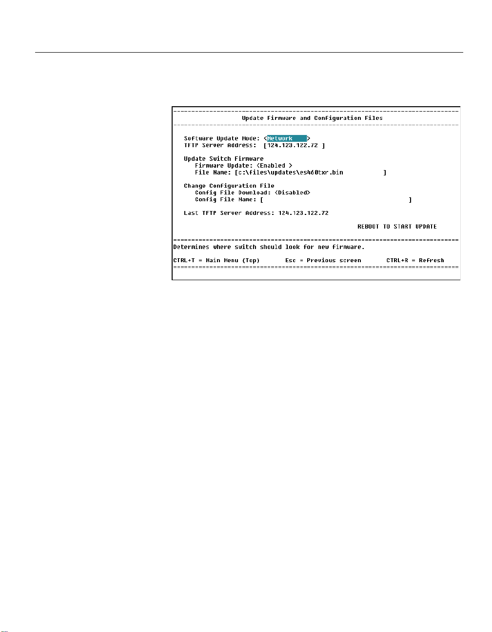
CHAPTER 5
LOCATION
Main Menu
Configure Management
Update Firmware and . . .
Intel Express 460T Standalone Switch Users Guide
Update Firmware and Config Files
Description
Software Update Mode: Use the z to select whether to update the
switch’s firmware over the network or through a SLIP connection.
TFTP Server Address: IP address of the server used as the TFTP server.
NOTE
Check the Intel Customer Support
Web site for firmware updates to
the Intel Express 460T Standalone
Switch.
82
Update Switch Firmware:
Firmware Update: Use the z to enable or disable the firmware
update. When enabled, the switch searches for the TFTP server
specified at the top of the screen and attempts to update the firmware.
File Name: Path and filename of the firmware located on the server.
Change Configuration File:
Config File Download: Use the z to enable or disable the ability
to download a configuration file. When this field is enabled, the switch
searches the TFTP server specified at the top of the screen.
Config File Name: Path and filename of the configuration file located on
the server.
Last TFTP Server Address: Displays the IP address of the last TFTP server
accessed by the switch.
REBOOT TO START UPDATE: Starts the update process. The switch
reboots and downloads the specified file.
Page 89

CHAPTER 5
LOCATION
Main Menu
Configure Management
Reset and Console Options
Using Local Management
Local Management
Reset and Console Options
Description
Reset options
Reboot switch: Resets the switch. If you changed the IP configuration
or login setting, the new settings take effect after you select this option.
Reset switch settings to factory defaults: Clears any IP address or
current changes and resets the switch back to its factory defaults. All
counters are cleared and the switch starts sending BOOTP requests.
Serial Port Settings
Port Setting: Configures the switch’s serial port for out-of-band (SLIP)
management. Press the z to toggle the field from <Console> to
<SLIP>. Settings take effect on the next reboot.
Console Timeout: Log a user out after a period of inactivity. Settings are
from 0-90 minutes in 15-minute increments. A setting of <0 mins> means
no timeout. The default is 60 minutes.
83
Page 90

CHAPTER 5
LOCATION
Main Menu
Configure VLAN
(if switch is in Default Mode)
Intel Express 460T Standalone Switch Users Guide
Configure VLAN Operation Mode
Description
Use this screen to activate or change the type of VLAN operating on the
switch. If there are no VLANs active on the switch, this is the first screen
displayed when you select Configure VLAN from the Main Menu. By
default, VLANs are not active on the 460T switch so they must be turned
on before you can start configuring them.
84
The 460T switch supports operation of only one type of VLAN at a time. It
supports multiple VLANs of the same type.
Select the type of VLAN: Press z to change the type of VLAN on
the switch. The 460T Switch supports three types of VLANs: port-based,
MAC-based, and IEEE 802.1Q (tag-based) VLANs.
APPLY: Activates the changes to the VLAN and reboots the switch. Note:
To change between VLAN types, the switch must be rebooted.
To change VLAN modes
1 On the Main Menu, select Configure VLAN.
2 On the Configure VLAN menu, select VLAN Operation Mode.
3 Press z to change the type of VLAN on the switch. Press e.
4 Select the APPLY button and press e. This reboots the switch and
changes the VLAN mode.
Page 91

CHAPTER 5
LOCATION
Main Menu
Configure VLAN
NOTE
You can have up to 12 port-based
VLANs on the switch.
Using Local Management
Local Management
Port-based VLANs
Description
Port-based VLANs are the simplest type of VLAN. You can use a portbased VLAN to create multiple VLANs each with its own broadcast domain
and member ports. For example, if port 5 is in VLAN_1 and port 10 is in
VLAN_2 the two ports cannot communicate with each other even though
they are part of the same switch. A port can be a member of only one portbased VLAN. Any port that is not a member of a user-defined VLAN is a
member of the DEFAULT_VLAN.
VLAN Operation Mode: Changes the type of VLAN operating on the
switch, or disables VLANs entirely.
Add a Port-Based VLAN: Creates a port-based VLAN and adds ports to the
VLAN.
Edit/Delete a Port-Based VLAN: Selects a VLAN so you can change port
membership in the VLAN, or removes a VLAN from the switch.
85
Page 92

CHAPTER 5
LOCATION
Main Menu
Configure VLAN
Add a Port-based VLAN
Intel Express 460T Standalone Switch Users Guide
Add a Port-based VLAN
Description
VLAN Name: Assigns a name to the VLAN. Names can consist of any
character (no spaces) and be up to 12 characters long. After a VLAN is
created the name cannot be changed. If you want to change the name, you
must delete the VLAN, create a new one, and assign the ports to the new
VLAN.
86
Port: Selects the port you want to participate in the VLAN.
Member: Determines which ports will participate in the VLAN. Ports can be
members of only one port-based VLAN. Press the z to toggle the
field for the following options:
<Yes > The port will be a member of the VLAN
<No > The port will not be a member of the VLAN.
– The port is part of an aggregated link.
N/A The port is already participating in another VLAN. Ports can
belong to only one VLAN.
APPLY: Creates the VLAN and activates the settings.
Page 93

CHAPTER 5
LOCATION
Main Menu
Configure VLAN
Edit/Delete a Port-based VLAN
Edit VLAN
Using Local Management
Local Management
To create a port-based VLAN
1 On the main menu, select Configure VLAN. Note: Make sure the
switch’s current VLAN operation mode is set to port-based VLAN. If
another type of VLAN is running, see “Configure VLAN Operation
Mode” to change the VLAN operation mode.
2 Select Add a Port-based VLAN and press e.
3 Type a name for the new VLAN and press e.
4 Select ports to add to the VLAN by using the z to toggle the
Member field to Yes.
5 Select the APPLY button and press e.
Edit/Delete a Port-based VLAN
Description
Action: Specifies whether to delete a VLAN or to change its port
membership. Press the z to toggle Edit or Delete and then use the
T or S keys to select a VLAN and press e. The DEFAULT_VLAN
cannot be deleted from the switch.
VLAN Name: The names of existing port-based VLANs.
Ports: Total number of member ports in the specified VLAN.
87
Page 94

CHAPTER 5
LOCATION
Main Menu
Configure VLAN
Edit/Delete a Port-based VLAN
Intel Express 460T Standalone Switch Users Guide
Change Port Membership in a VLAN
Description
This screen is similar to the VLAN creation screen. You can change the
membership status of ports within the VLAN but you cannot change the
name of the VLAN.
VLAN Name: The name of the VLAN you are editing.
88
Port: Selects the port you want to participate in the VLAN.
Member: This option determines which ports will participate in the current
VLAN. Ports can be members of only one VLAN. Press the z to
toggle the field for the following options:
<Yes> The port will be a member of the VLAN.
<No > The port will not be a member of the VLAN.
– The port is part of an aggregated link.
N/A The port is already participating in another VLAN. Ports can
belong to only one VLAN.
APPLY: Activates the settings.
Page 95

CHAPTER 5
LOCATION
Main Menu
Configure VLAN
Using Local Management
Local Management
MAC-Based VLANs
Description
VLAN Operation Mode: Changes the type of VLAN operating on the
switch, or disables VLANs entirely.
Add a MAC-based VLAN: Creates a new MAC-based VLAN. You can
create up to 12 MAC-based VLANs on the switch.
Edit/Delete a MAC-based VLAN: Adds member MAC addresses to a MACbased VLAN, or deletes a VLAN entirely.
89
Page 96

CHAPTER 5
LOCATION
Main Menu
Configure VLAN
Add a MAC-based VLAN
Intel Express 460T Standalone Switch Users Guide
Add a MAC-Based VLAN
Description
VLAN Name: Assigns a name to the VLAN. The name can consist of any
character (no spaces) and be up to 12 characters long. After a VLAN is
created the name cannot be changed. If you want to change the name you
must delete the VLAN, create a new one, and assign the addresses to the
new VLAN.
90
VLAN Name: The name of existing MAC-based VLANs.
MAC Addresses: Total number of MAC addresses that belong to the
VLAN. The switch supports up to 256 address entries per VLAN.
APPLY: Creates the VLAN.
Page 97
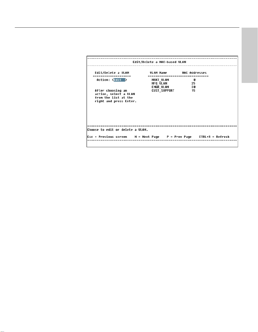
CHAPTER 5
LOCATION
Main Menu
Configure VLAN
Edit/Delete a MAC-based VLAN
Using Local Management
Local Management
Edit/Delete a MAC-Based VLAN
Description
Action: Specify whether to edit a VLAN’s membership or delete the VLAN
entirely. Use the z to toggle <Edit> to add/remove member MAC
addresses or <Delete> to remove a VLAN from the switch.
VLAN Name: The names of MAC-based VLANs active on the switch.
MAC Addresses: Total number of MAC addresses in the specified VLAN.
91
Page 98
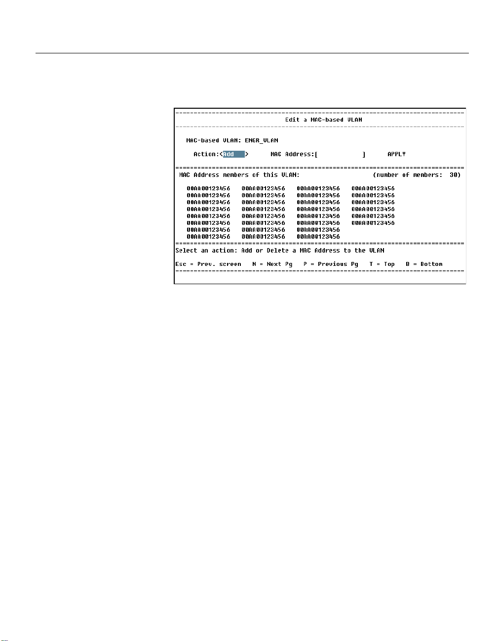
CHAPTER 5
LOCATION
Main Menu
Configure VLAN
Edit/Delete a Mac-based VLAN
Edit a MAC-based VLAN
Intel Express 460T Standalone Switch Users Guide
Edit a MAC-based VLAN
Description
Use this screen to add or remove member MAC addresses from a MACbased VLAN.
Action: Use the z to toggle the field and specify whether to add a
new MAC address to the VLAN or to remove an address that is currently in
the VLAN.
92
MAC Address: Type the MAC address (without hyphens) of a device such
as a PC or server to be a VLAN member.
APPLY: Makes changes to the VLAN’s membership.
Page 99

CHAPTER 5
Using Local Management
Local Management
To create a MAC-Based VLAN
When creating a MAC-based VLAN, unlike port-based VLANs, you must
first create the VLAN and then add members to the VLAN.
1 Select Configure VLAN.
Note: Make sure the switch’s current VLAN operation mode is set to
MAC-based VLAN. If another type of VLAN is running, see “Configure
VLAN Operation Mode” to change the VLAN operation mode.
2 Select Add a MAC-based VLAN and press e.
3 Type a name for the new VLAN and press e.
4 Select the APPLY button and press e. The new VLAN appears in
the list on the left.
To add MAC addresses to a MAC-based VLAN
1 On the Configure VLAN menu select Edit/Delete a MAC-based VLAN
and press e.
2 Set the Action toggle to Edit using the z and press e.
3 Select a VLAN from the list using the arrow keys and press e.
4 On the Edit MAC-based VLAN screen, set the Action toggle to Add
using the z and press e.
5 Type the MAC address you want to add to the VLAN.
6 Select the APPLY button and press e. The new MAC address
appears in the list below.
To remove a MAC-based VLAN
1 On the Configure VLAN menu select Edit/Delete a MAC-based VLAN
and press e.
2 Set the Action toggle to Delete using the z and press e.
3 Select a VLAN from the list using the arrow keys and press e. The
VLAN is removed from the list.
Security considerations
MAC-based VLANs, as designed on the 460T switch, are meant to limit
broadcast and multicast traffic over the network. The switch relies on
limiting broadcast traffic to constrain network visibility of network
applications (such as TCP/IP) that rely on broadcasts (such as ARP) for
station discovery. The 460T MAC-based VLANs are not intended to be a
secure solution. For secure VLANs use either port-based or IEEE 802.1Qbased VLANs.
93
Page 100

CHAPTER 5
LOCATION
Main Menu
Configure VLAN
Intel Express 460T Standalone Switch Users Guide
Configure 802.1Q VLANs
Description
VLAN operation mode: Change the type of VLAN operating on the switch,
or disable VLANs entirely.
Create an IEEE 802.1Q VLAN: Create a new 802.1Q VLAN and add ports
to the VLAN.
94
Edit/Delete an IEEE 802.1Q VLAN: Change port membership of an existing
VLAN, or remove a VLAN from the switch.
Configure VLAN ID for untagged devices (PVID): Assign a VLAN to
incoming packets without a VID.
GVRP and ingress filter settings: Set port-level options for dynamic VLAN
creation and packet filtering by VLAN.
 Loading...