

Page 1
Audio Video Control Receiver
Contents
Before using
Important Safeguards........................ 2
Precautions ....................................... 3
Features............................................. 4
Supplied accessories......................... 4
Before operating this unit................. 5
DTR-5
Instruction Manual
STANDBY/ON
STANDBY
POWER
ON
OFF
SPEAKERSAB
PHONES
DIMMER
DISPLAY
VIDEO 1
MULTI
CH
INPUT
FM
MEMORY
LISTENING MODE
/DTS
SURROUND
STEREO
5
CH STEREO
VIDEO 3
VIDEO 2
DIGITAL/
TUNING
DSP
FM
ANALOG
UPDOWN
LATE
NIGHT /
FRONT
AM PHONO C
SP / SYS
SETUP
PRESET / MODE ADJ
DOW NUP
ENTER / SCAN
EFFECT
Re -EQ
CH LEVEL
LFE LEVEL
CONTROL
MODE
TAPEDVD
MUTE /
Thank you for purchasing the Integra Audio Video
Control Receiver.
Please read this manual thoroughly before making
connections and turning on the power.
Following the instructions in this manual will enable
you to obtain optimum performance and listening
enjoyment from your new Audio Video Control
Receiver.
Please retain this manual for future reference.
MASTER VOLUME
MODE
TREBLE
BASS
D
Preparation
Audio equipment connections.......... 6
Video equipment connections .......... 7
Connecting other devices ................. 8
Connecting speakers....................... 10
Positioning speakers....................... 11
Connecting the power..................... 11
Making antenna connections.......... 12
Operation
Speaker setup.................................. 14
Selecting a sound source ................ 17
Using Listening Mode.................... 21
Tuning in a radio station................. 24
Using preset radio stations.............. 25
Recording a source......................... 27
Enjoying Music and Movies
in the Sub-room........................... 29
Using the remote controller............ 31
Programming the remote controller
codes of other devices into the
RC-391M..................................... 34
Using a Macro function.................. 36
Appendix
Troubleshooting guide.................... 40
Specifications ................................. 41
Control guide
Control positions and names .......... 42
Page 2
1.
WARNING:
TO REDUCE THE RISK OF FIRE OR ELECTRIC SHOCK,
DO NOT EXPOSE THIS APPLIANCE TO RAIN OR
MOISTURE.
CAUTION:
TO REDUCE THE RISK OF ELECTRIC SHOCK, DO NOT
REMOVE COVER (OR BACK). NO USER-SERVICEABLE
PARTS INSIDE. REFER SERVICING TO QUALIFIED
SERVICE PERSONNEL.
Important Safeguards
Read Instructions – All the safety and operating instructions
should be read before the appliance is operated.
2. Retain Instructions – The safety and operating instructions
should be retained for future reference.
3.
Heed Warnings
operating instructions should be adhered to.
4.
Follow Instructions
should be followed.
5.
Water and Moisture
water – for example, near a bathtub, washbowl, kitchen sink,
laundry tub, in a wet basement, or near a swimming pool, and
the like.
6.
Carts and Stands
cart or stand that is recommended by the manufacturer.
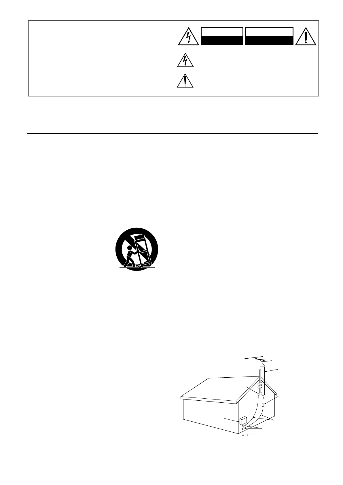
6A. An appliance and cart combina-
tion should be moved with care.
Quick stops, excessive force,
and uneven surfaces may cause
the appliance and cart combination to overturn.
7.
Wall or Ceiling Mounting
to a wall or ceiling only as recommended by the manufacturer.
8.
Ventilation
tion or position does not interfere with its proper ventilation.
For example, the appliance should not be situated on a bed,
sofa, rug, or similar surface that may block the ventilation
openings; or if placed in a built-in installation, such as a bookcase or cabinet that may impede the flow of air through the
ventilation openings, there should be free space of at least 20
cm (8 in.) and an opening behind the appliance.
9.
Heat
– The appliance should be situated away from heat
sources such as radiators, heat registers, stoves, or other appliances (including amplifiers) that produce heat.
10.
Power Sources –
power supply only of the type described in the operating
instructions or as marked on the appliance.
11.
Polarization
plug having one blade wider than the other, please read the following information:
The polarization of the plug is a safety feature. The polarized
plug will only fit the outlet one way. If the plug does not fit
fully into the outlet, try reversing it. If there is still trouble, the
user should seek the services of a qualified electrician. Under
no circumstances should the user attempt to defeat the polarization of the plug.
12.
Power-Cord Protection
routed so that they are not likely to be walked on or pinched by
items placed upon or against them, especially near plugs, convenience receptacles, and the point where they exit from the
appliance.
13.
Cleaning
mended by the manufacturer.
2
– All warnings on the appliance and in the
– All operating and use instructions
– The appliance should not be used near
– The appliance should be used only with a
PORTABLE CART WARNING
S3125A
– The appliance should be mounted
– The appliance should be situated so that its loca-
The appliance should be connected to a
– If the appliance is provided with a polarized
– Power-supply cords should be
– The appliance should be cleaned only as recom-
WARNING
RISK OF ELECTRIC SHOCK
DO NOT OPEN
The lightning flash with arrowhead symbol, within an equilateral
triangle, is intended to alert the user to the presence of uninsulated
“dangerous voltage” within the product’s enclosure that may be of
sufficient magnitude to constitute a risk of electric shock to persons.
The exclamation point within an equilateral triangle is intended to
alert the user to the presence of important operating and maintenance
(servicing) instructions in the literature accompanying the appliance.
14.
Power Lines
– An outdoor antenna should be located away
AVIS
RISQUE DE CHOC ELECTRIQUE
OUVRIR
NE PAS
from power lines.
15.
Nonuse Periods
– The power cord of the appliance should be
unplugged from the outlet when left unused for a long period
of time.
16.
Object and Liquid Entry
– Care should be taken so that
objects do not fall and liquids are not spilled into the enclosure
through openings.
17.
Damage Requiring Service
– The appliance should be serviced by qualified service personnel when:
A. The power-supply cord or the plug has been damaged; or
B. Objects have fallen, or liquid has been spilled into the
appliance; or
C. The appliance has been exposed to rain; or
D. The appliance does not appear to operate normally or
exhibits a marked change in performance; or
E. The appliance has been dropped, or the enclosure damaged.
18.
Servicing
– The user should not attempt to service the appliance beyond that described in the operating instructions. All
other servicing should be referred to qualified service personnel.
19.
Outdoor Antenna Grounding
– If an outside antenna is connected to the receiver, be sure the antenna system is grounded
so as to provide some protection against voltage surges and
built up static charges. Article 810 of the National Electrical
Code, ANSI/NFPA 70, provides information with regard to
proper grounding of the mast and supporting structure, grounding of the lead-in wire to an antenna-discharge unit, size of
grounding conductors, location of antenna-discharge unit, connection to grounding electrodes, and requirements for the
grounding electrode. See Figure 1.
FIGURE 1:
EXAMPLE OF ANTENNA GROUNDING AS PER NATIONAL
ELECTRICAL CODE
ANTENNA
LEAD IN
WIRE
GROUND
CLAMP
ANTENNA
DISCHARGE UNIT
(NEC SECTION 810-20)
ELECTRIC
SERVICE
EQUIPMENT
NEC – NATIONAL ELECTRICAL CODE
S2898A
GROUNDING CONDUCTORS
(NEC SECTION 810-21)
GROUND CLAMPS
POWER SERVICE GROUNDING
ELECTRODE SYSTEM
(NEC ART 250, PART H)
Page 3

Precautions
1. Warranty Claim
You can find the serial number on the rear panel of this unit. In case
of warranty claim, please report this number.
2. Recording Copyright
Recording of copyrighted material for other than personal use is
illegal without permission of the copyright holder.
3. AC Fuse
The fuse is located inside the chassis and is not user-serviceable. If
power does not come on, contact your Onkyo authorized service
station.
4. Care
From time to time you should wipe the front and rear panels and the
cabinet with a soft cloth. For heavier dirt, dampen a soft cloth in a
weak solution of mild detergent and water, wring it out dry, and
wipe off the dirt. Following this, dry immediately with a clean cloth.
Do not use rough material, thinners, alcohol or other chemical solvents or cloths since these could damage the finish or remove the
panel lettering.
5. Power
WARNING
BEFORE PLUGGING IN THE UNIT FOR THE FIRST TIME,
READ THE FOLLOWING SECTION CAREFULLY.
The voltage of the available power supply differs according to
country or region. Be sure that the power supply voltage of the area
where this unit will be used meets the required voltage (e.g., AC
120 V, 60 Hz) written on the rear panel.
W orldwide models are equipped with a voltage selector to conform
to local power supplies. Be sure to set this switch to match the voltage of the power supply in your area before plugging in the unit.
For U.S. model
Note to CATV system installer:
This reminder is provided to call the CATV system installer’s
attention to Article 820-40 of the NEC, ANSI/NFPA 70, which provides guidelines for proper grounding and, in particular, specifies
that the cable ground shall be connected to the grounding system of
the building, as close to the point of cable entry as practical.
FCC Information for User
CAUTION:
The user changes or modifications not expressly approved by the
party responsible for compliance could void the user’s authority to
operate the equipment.
NOTE:
This equipment has been tested and found to comply with the limits
for a Class B digital device, pursuant to Part 15 of the FCC Rules.
These limits are designed to provide reasonable protection against
harmful interference in a residential installation. This equipment
generates, uses and can radiate radio frequency energy and, if not
installed and used in accordance with the instructions, may cause
harmful interference to radio communications. However, there is no
guarantee that interference will not occur in a particular installation.
If this equipment does cause harmful interference to radio or television reception, which can be determined by turning the equipment
off and on, the user is encouraged to try to correct the interference by
one or more of the following measures:
Reorient or relocate the receiving antenna.
•
•
Increase the separation between the equipment and receiver.
•
Connect the equipment into an outlet on a circuit different from
that to which the receiver is connected.
Consult the dealer or an experienced radio/TV technician for help.
•
For Canadian model
CAUTION:
THE CLASS B LIMITS FOR RADIO NOISE EMISSION FROM
DIGITAL APPARATUS SET OUT IN THE RADIO INTERFERENCE REGULATIONS OF THE CANADIAN DEPARTMENT
OF COMMUNICATIONS.
For models having a power cord with a polarized plug:
CAUTION:
BLADE OF PLUG TO WIDE SLOT, FULLY INSERT.
THIS DIGITAL APPARATUS DOES NOT EXCEED
TO PREVENT ELECTRIC SHOCK, MATCH WIDE
Modele pour les Canadien
ATTENTION: L'INTERFÉRENCE RADIO ÉLECTRIQUE
GÉNÉRÉE PAR CET APPAREIL NUMÉRIQUE DE TYPE B NE
DÉPASSE PAS LES LIMITES ÉNONCÉES DANS LE RÈGLEMENT SUR LES PERTURBATIONS RADIO ÉLECTRIQUES,
SECTION APPAREIL NUMÉRIQUE, DU MINISTÈRE DES
COMMUNICATIONS.
Sur les modèles dont la fiche est polarisée:
ATTENTION:
INTRODUIRE LA LAME LA PLUS LARGE DE LA FICHE
DANS LA BORNE CORRESPONDANTE DE LA PRISE ET
POUSSER JUSQU’AU FOND.
POUR ÉVITER LES CHOCS ÉLECTRIQUES,
3
Page 4
Features
®*1
■
DTS
, Dolby
Decoders
■
5.1 Channel Direct Inputs
■
Cinema Re-EQ™
High Definition DSP
■
■
8 DSP Listening Modes
■
Full Bandwidth Power to 5 Main Channels
■
Wide Range Amplifier Technology (WRAT)
■
High-Current, Low-Impedance 6-Ohm Drive
■
Discrete Output Stage Circuitry for 5 Main Channels
■
Massive Isolated Transformer
■
High-Quality Aluminum-Extruded Heat Sinks
■
Audiophile-Grade “Fine Gold” Capacitors
■
A + B Speaker Drive
■
Advanced 96 kHz/24-Bit D/A Converter
■
Late Night Mode
■
3 Assignable Digital Inputs (2 coaxial and 1 optical)
■
Multiway Speaker Binding Posts for the front left,
right and center channels
■
Dedicated Line-Level Subwoofer Pre Out
■
4 A/V and 3 Audio Inputs (all gold-plated)
■
Phono Input
■
Multiroom Jack for compatibility with Xantech
®*5
Niles
and the more popular multiroom A/V distri-
bution and control systems
■
30 FM/AM Random Presets
■
FM Auto T uning
■
2-Mode Display Dimmer
■
Headphone Jack (standard size)
■
Audio Mute (remote)
■
Sleep Timer (remote)
■
Battery-Free Memory Backup
■
2 Switched AC Convenience Outlets
■
Detachable, High-Current-Capacity Power Cord
■
Hand-Brushed Aluminum Front Panel
■
Powerful Learning Remote with Joy Stick and Macro
Functions
*1
Manufactured under license from Digital Theater Systems, Inc. US
Pat. No.5,451,942 and other worldwide patents issues and pending.
“DTS” and “DTS Digital Surround” are trademarks of Digital Theater
Systems, Inc.© 1996 Digital Theater Systems, Inc. All rights reserved.
*2
Manufactured under license from Dolby Laboratories.
“Dolby”, “Pro Logic” and the double-D symbol are trademarks of
Dolby Laboratories. Confidential Unpublished Works. ©1992-1997
Dolby Laboratories, Inc. All rights reserved.
*3
Re-Equalization and the “Re-EQ” logo are trademarks of Lucasfilm Ltd.
Manufactured under license of Lucasfilm Ltd..
*4
Xantech is a registered trademark of Xantech Corporation.
*5
Niles is a resitrered trademark of Niles Audio Corporation.
®*2
Digital and Dolby
*3
Circuitry
®
Pro Logic
®*4
Supplied accessories
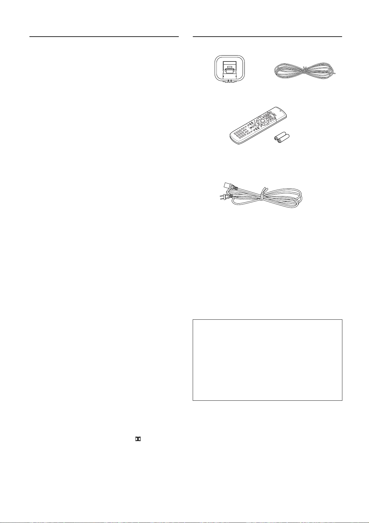
Check that the following accessories are supplied with this unit.
AM loop antenna × 1
Remote controller (RC-391M) × 1
Batteries (size AA or UM-3) × 2
Power cable × 1
,
Memory Preservation
This unit does not require memory preservation batteries. A
built-in memory power back-up system preserves the contents
of the memory during power failures and even when the unit is
unplugged. The unit must be plugged in order to charge the
back-up system.
The memory preservation period after the unit has been
unplugged varies depending on climate and placement of the
unit. On the average, memory contents are protected over a
period of a few weeks after the last time the unit has been
unplugged. This period is shorter when the unit is exposed to a
highly humid climate.
FM antenna × 1
4
Page 5
Before operating this unit
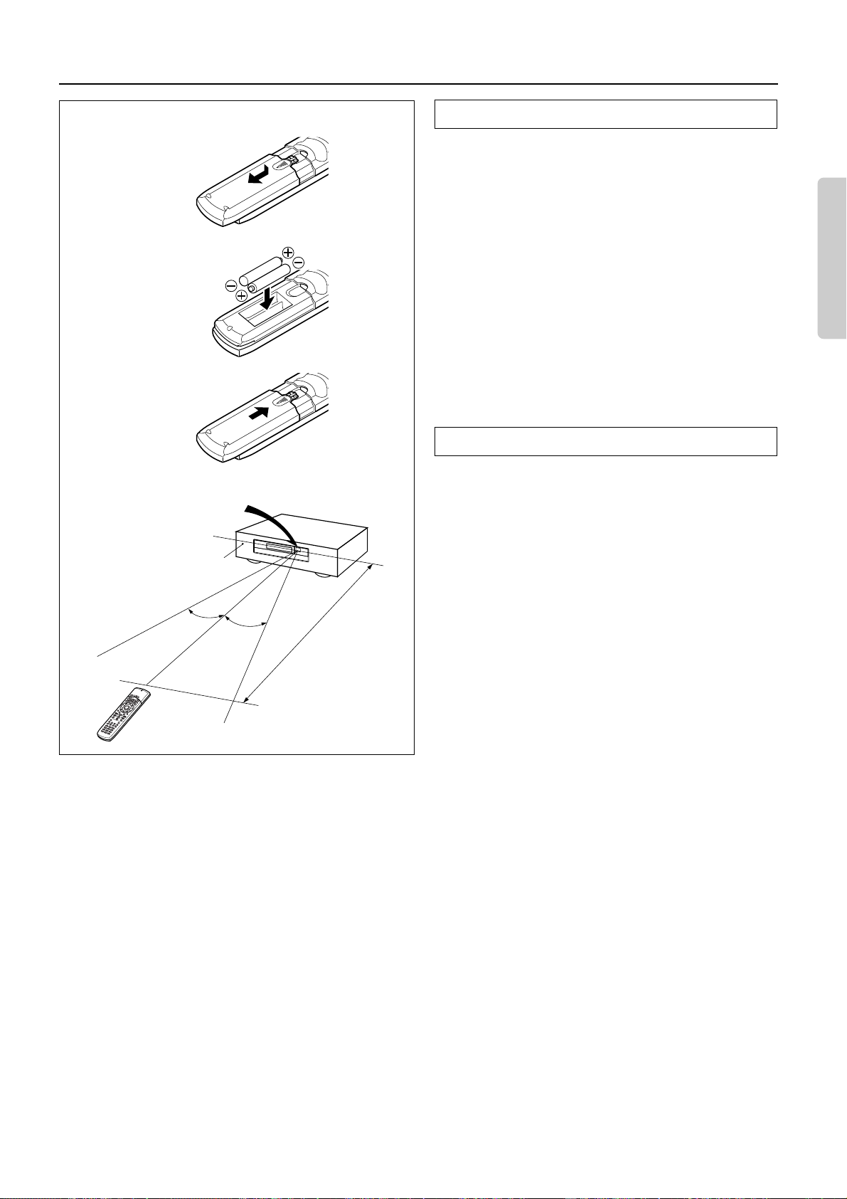
Installing the remote controller batteries
1
2
3
Remote control sensor
STANDBY indicator
30˚
30˚
DTR-5
approx. 5 m
(16 feet)
1. Remove the battery compartment cover by pressing the tab and
lifting up the cover.
2. Insert two AA (R6- or UM-3)-size batteries into the battery compartment. Carefully follow the polarity diagram (positive (+) and negative (–) symbols) inside the battery compartment.
3. After batteries are installed and seated correctly, replace the compartment cover.
Notes
•
Do not mix new batteries with old batteries or different kinds of
batteries.
•
To avoid corrosion, remove the batteries if the remote controller
is not to be used for a long time.
•
Remove dead batteries immediately to avoid damage from corrosion. If the remote controller doesn’t operate smoothly,
replace both the batteries at the same time.
•
The life of the batteries supplied is about six months but this
will vary depending on usage.
Using the remote controller
Point the remote controller toward the remote control sensor.
The STANDBY indicator lights up when the unit receives a signal
from the remote controller.
Notes
•
Place the unit away from strong light such as direct sunlight or
inverted fluorescent light which can pre vent proper operation of the
remote controller.
Using another remote controller of the same type in the same
•
room or using the unit near equipment which uses infrared rays
may cause operational interference.
Do not put any object such as a book on the remote controller.
•
The buttons of the remote controller may be pressed by mistake
and drain the batteries.
•
Make sure the audio rack doors do not have colored glass. Placing the unit behind such doors may prevent proper remote controller operation.
If there is any obstacle between the remote controller and the
•
remote control sensor, the remote controller will not operate.
5
Page 6
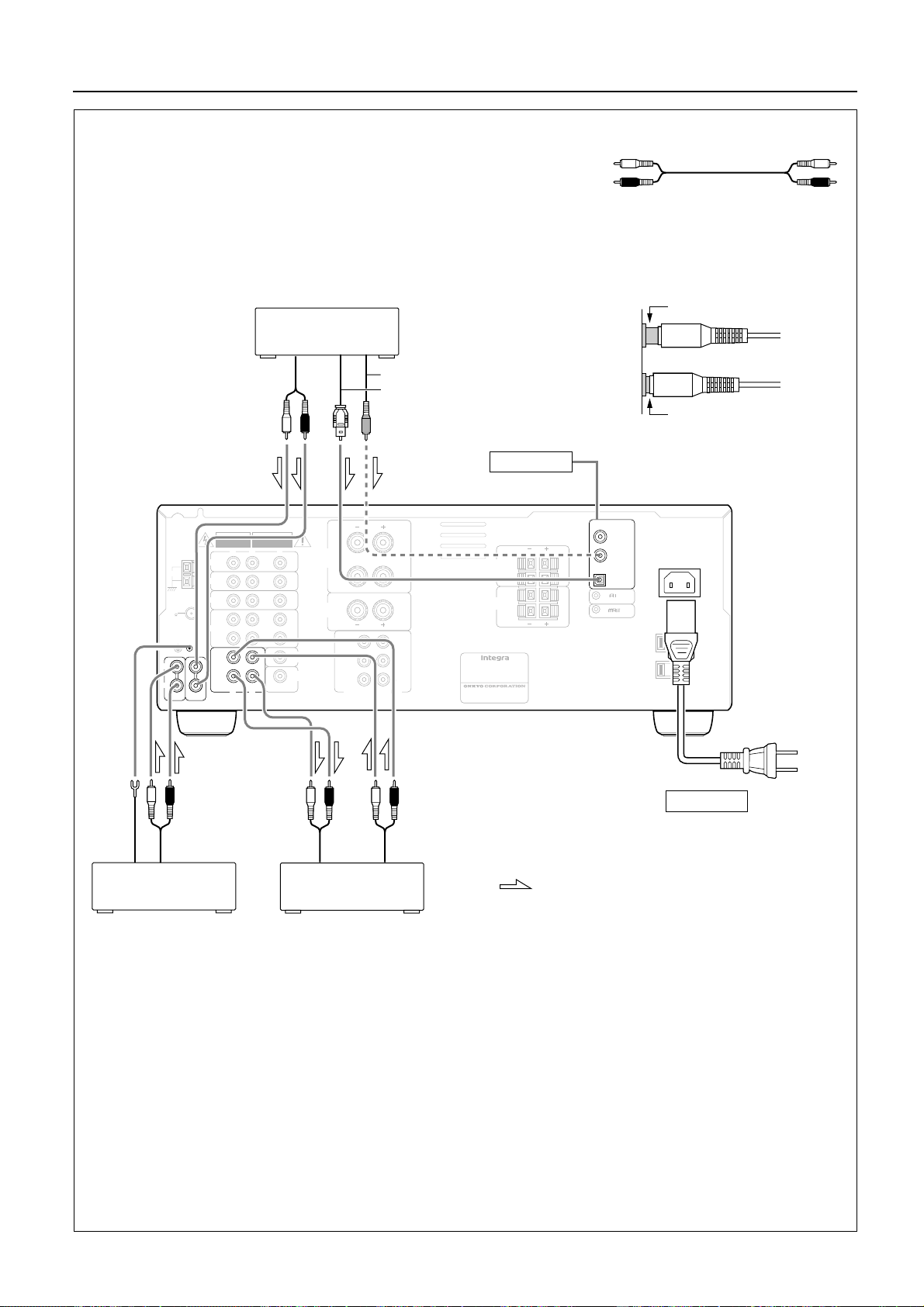
Audio equipment connections
•
On each pair of input jacks, a red connector (marked R) corresponds to the right
channel, and a white connector (marked L) to the left channel.
•
Please refer to the instruction manual of each component when making any connections.
•
This receiver is designed for use with turntables using moving magnet cartridges.
•
Insert the plugs and connectors securely. Remember that improper connection
can result in noise, poor performance, or damage to the equipment.
CD Player
ANTENNA
L
R
PHONO
OUTPUT
(ANALOG)
DO NOT OPEN
R
)
)
R
AVIS
RISQUE DE CHOC ELECTRIQUE
NE PAS OUVRIR
V
L
I
N
I N
I
N
N
I
OUT
V
L
MONITOR
OUT
SUBWOOFER
PRE OUT
FRONT
SPEAKERS
A
CENTER
SPEAKER
FRONT
SURROUND
CENTER
WARNING
RISK OF ELECTRIC SHOCK
DVD
AM
VIDEO 3
VIDEO 2
FM
75
VIDEO 1
GND
(
PLAY
N
I
TAPE
OUT
(
REC
C D
OUTPUT (COAXIAL)
OUTPUT (DIGITAL)
L
R
MULT I CHANNEL I NPUT
L
R
R
L
L
R
SUB
WOOFER
FRONT
SPEAKERS
B
SURROUND
CAUTION: SPEAKER IMPEDANCE
6 OHMS MIN. PER EACH
SPEAKER TERMINAL
SPEAKERS
AV RECEIVER
MODEL NO. DTR-5
RATING:
AC120V 60Hz 3.9A
2-1, NISSHIN-CHO, NEYAGAWA-SHI,OSAKA,
JAPAN
MANUFACTURED IN MALA
See page 7
L
R
L
R
YSIA
L (Left)
R (Right)
L
R
Improper connection
Insert completely
Audio connection cable
DIGITAL INPUT
COAXIAL 2
L
R
L
R
COAXIAL 1
OPTICAL
REMOTE CONTROL
AC I NLET
AC 120V 60Hz
SWITCHED
TOTAL 120W 1A MAX.
Power cable
(included)
To wall
outlet
See page 9
Do not plug in the power
cord until all connections
Ground
OUTPUT
INPUT
(REC)
OUTPUT
(PLAY)
have been made.
Turntable
Tape Deck
: signal flow
• A DVD or other component equipped with a digital output can be connected to this receiver. The digital connection must be
used in conjunction with an analog connection, because if the analog cable is disconnected, the audio output from TAPE OUT
(REC) and VIDEO 1 OUT will not work.
6
Page 7
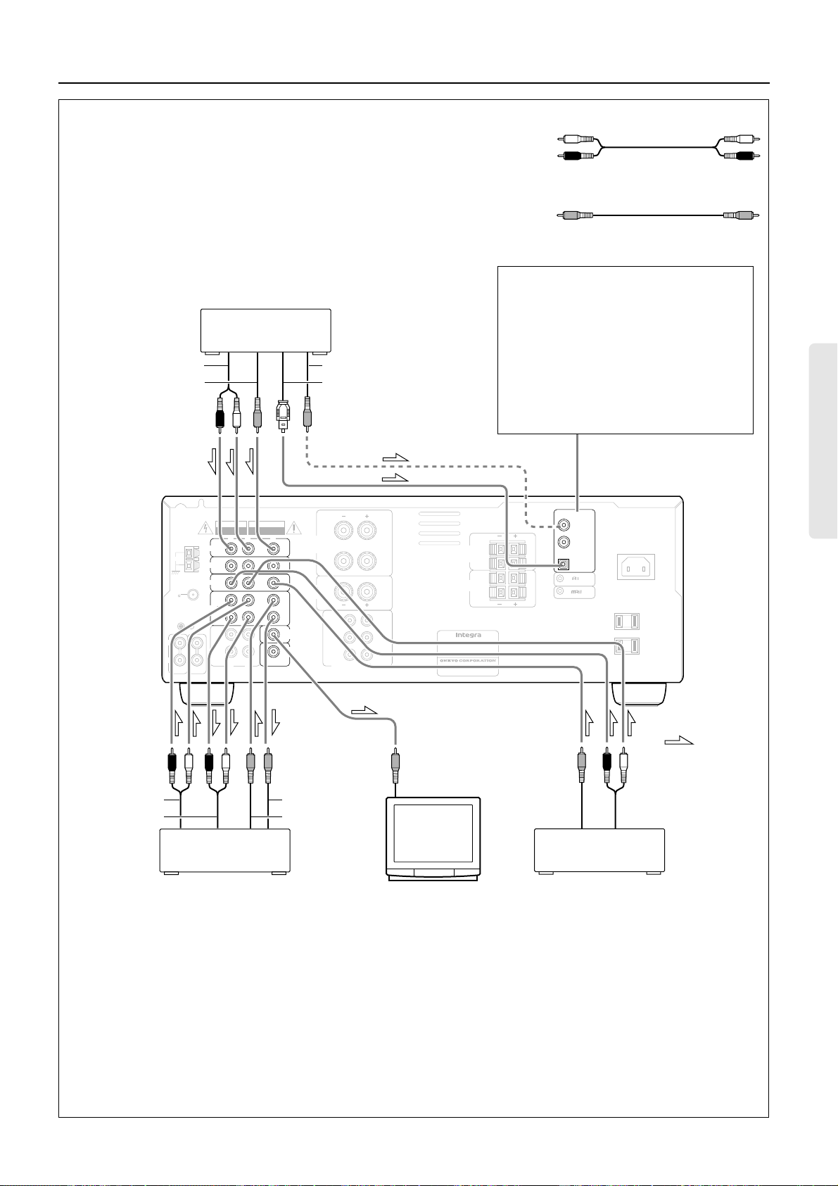
Video equipment connections
•
On each pair of input jacks, a red connector (marked R) corresponds to the right
channel, and a white connector (marked L) to the left channel.
• A yellow connector (marked V) is used for video connection.
• Please refer to the instruction manual of each component when making any con-
nections.
Digital audio connections
This receiver has a powerful digital signal
processor for use with DVD players, DAT
decks, and CD players. The digital inputs,
COAXIAL 1, 2 and OPTICAL can be
assigned to individual input selector buttons,
so when an input selector button is pressed, the
assigned digital input is used instead of the
corresponding analog input. (See page 18.)
L
B
R
L
R
DTR-5
YSIA
AUDIO OUTPUT
VIDEO OUTPUT
ANTENNA
AM
FM
75
GND
L
R
PHONO
VIDEO 3
VIDEO 2
VIDEO 1
C D
WARNING
RISK OF ELECTRIC SHOCK
DO NOT OPEN
R
DVD
(
)
PLAY
N
I
TAPE
OUT
(
)
REC
R
DVD Player
AVIS
RISQUE DE CHOC ELECTRIQUE
NE PAS OUVRIR
V
L
I
N
I N
I
N
N
I
OUT
V
L
MONITOR
OUT
SUBWOOFER
PRE OUT
DIGITAL COAXIAL OUTPUT
DIGITAL OPTICAL OUTPUT
FRONT
SPEAKERS
A
CENTER
SPEAKER
FRONT
SURROUND
CENTER
L
R
MULT I CHANNEL I NPUT
L
R
CAUTION: SPEAKER IMPEDANCE
6 OHMS MIN. PER EACH
SPEAKER TERMINAL
R
L
L
R
SUB
WOOFER
FRONT
SPEAKERS
SURROUND
SPEAKERS
AV RECEIVER
MODEL NO.
RATING:
AC120V 60Hz 3.9A
2-1, NISSHIN-CHO, NEYAGAWA-SHI,OSAKA,
JAPAN
MANUFACTURED IN MALA
L (Left)
Audio connection cable
R (Right)
Video connection cable
V (Video) V
DIGITAL INPUT
COAXIAL 2
L
R
L
R
COAXIAL 1
OPTICAL
REMOTE CONTROL
AC I NLET
AC 120V 60Hz
SWITCHED
TOTAL 120W 1A MAX.
L
R
: signal flow
VIDEO IN
AUDIO OUT
AUDIO IN
Video Cassette Recorder
VIDEO IN
VIDEO OUT
VIDEO OUT
AUDIO OUT
VDP Player
Monitor TV
Notes:
• When using a playback-only VCR, connect it to VIDEO 2 or VIDEO 3. If you connect it to VIDEO 1, you need to make only the out-
put connections.
• This receiver can be used with only a monitor TV equipped with a video input jack.
• Interference may be caused between the TV and this receiver. If this interference occurs, place the receiver and the TV as f ar apart
as possible. We do not recommend the use of a common TV/FM antenna (see antenna section).
• A DVD or other component equipped with a digital output can be connected to this receiver. The digital connection must be used in
conjunction with an analog connection, because if the analog cable is disconnected, the audio output from TAPE OUT (REC) and
VIDEO 1 OUT will not work.
• Remove the protective cap attached to the DIGITAL INPUT (OPTICAL) jack before making the connection. When this jack is not
used, replace the protective cap.
7
Page 8
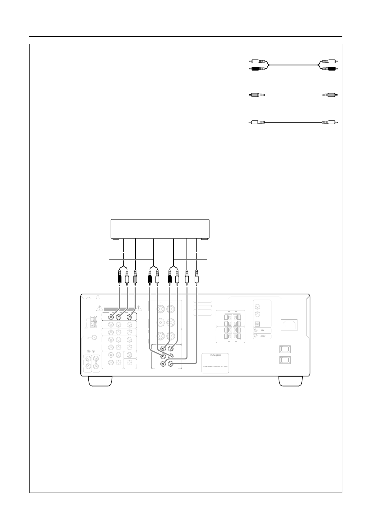
Connecting other devices
• On each pair of input jacks, a red connector (marked R) corresponds to the right
channel, and a white connector (marked L) to the left channel.
L (Left)
Audio connection cable
• A yellow connector (marked V) is used for video connection.
• Please refer to the instruction manual of each component when making any con-
nections.
Decoder with 5.1 channel output
You may connect the 5.1 channel outputs of an external decoder (such as MPEG decoder) to the MULTI CHANNEL INPUTs of this
unit.
Use the DVD player or decoder controls to adjust the speaker settings for multi-channel input.
DVD player or
a decoder with Multi (5.1) channel outputs
R (Right)
Video connection cable
V (Video) V
Monaural audio cable (mono)
L
R
AUDIO OUT
VIDEO OUT
SURROUND OUT
ANTENNA
DVD
AM
VIDEO 3
VIDEO 2
FM
75
VIDEO 1
GND
(
PLAY
PHONO
TAPE
(
C D
L
R
WARNING
RISK OF ELECTRIC SHOCK
DO NOT OPEN
R
)
N
I
OUT
)
REC
R
AVIS
RISQUE DE CHOC ELECTRIQUE
NE PAS OUVRIR
V
L
I
N
I N
I
N
N
I
OUT
MONITOR
V
OUT
SUBWOOFER
PRE OUT
L
FRONT
SPEAKERS
A
CENTER
SPEAKER
L
R
FRONT
R
SURROUND
R
CENTER
MULT I CHANNEL I NPUT
L
R
CAUTION: SPEAKER IMPEDANCE
6 OHMS MIN. PER EACH
SPEAKER TERMINAL
L
L
SUB
WOOFER
SUBWOOFER OUT
CENTER OUT
MULTI CHANNEL FRONT OUT
DIGITAL INPUT
COAXIAL 2
L
FRONT
SPEAKERS
B
R
L
SURROUND
SPEAKERS
R
AV RECEIVER
MODEL NO. DTR-5
RATING:
AC120V 60Hz 3.9A
2-1, NISSHIN-CHO, NEYAGAWA-SHI,OSAKA,
JAPAN
MANUFACTURED IN MALA
YSIA
L
R
L
R
COAXIAL 1
OPTICAL
REMOTE CONTROL
AC I NLET
AC 120V 60Hz
SWITCHED
TOTAL 120W 1A MAX.
8
Page 9
Connecting other devices
DIGITAL INPUT
AVIS
WARNING
RISK OF ELECTRIC SHOCK
RISQUE DE CHOC ELECTRIQUE
DO NOT OPEN
NE PAS OUVRIR
V
L
R
ANTENNA
N
I
DVD
AM
I N
VIDEO 3
N
I
VIDEO 2
FM
75
I
N
VIDEO 1
GND
OUT
(
)
PLAY
MONITOR
I
N
V
OUT
TAPE
L
R
C D
PHONO
ANTENNA
AM
FM
75
GND
L
R
PHONO
SUBWOOFER
OUT
PRE OUT
(
)
REC
L
R
AVIS
WARNING
RISK OF ELECTRIC SHOCK
RISQUE DE CHOC ELECTRIQUE
DO NOT OPEN
NE PAS OUVRIR
V
L
R
N
I
DVD
I N
VIDEO 3
N
I
VIDEO 2
I
N
VIDEO 1
OUT
(
)
PLAY
I
N
V
TAPE
OUT
(
)
REC
L
R
C D
MONITOR
OUT
SUBWOOFER
PRE OUT
FRONT
SPEAKERS
CENTER
SPEAKER
A
RLR
FRONT
SURROUND
CENTER
MULT I CHANNEL I NPUT
FRONT
SPEAKERS
A
CENTER
SPEAKER
FRONT
SURROUND
CENTER
R
R
RLR
R
R
MULT I CHANNEL I NPUT
L
CAUTION: SPEAKER IMPEDANCE
L
L
SUB
WOOFER
L
CAUTION: SPEAKER IMPEDANCE
L
L
SUB
WOOFER
6 OHMS MIN. PER EACH
SPEAKER TERMINAL
2-1, NISSHIN-CHO, NEYAGAWA-SHI,OSAKA,
JAPAN
6 OHMS MIN. PER EACH
SPEAKER TERMINAL
FRONT
SPEAKERS
B
SURROUND
SPEAKERS
AV RECEIVER
MODEL NO. DTR-5
RATING:
AC120V 60Hz 3.9A
MANUFACTURED IN MALA
FRONT
SPEAKERS
B
SURROUND
SPEAKERS
AV RECEIVER
MODEL NO. DTR-5
RATING:
AC120V 60Hz 3.9A
2-1, NISSHIN-CHO, NEYAGAWA-SHI,OSAKA,
JAPAN
MANUFACTURED IN MALA
COAXIAL 2
COAXIAL 1
L
L
OPTICAL
R
R
L
L
REMOTE CONTROL
R
R
YSIA
U.S.A. and Canadian models
Capacity is total 120 watts.
DIGITAL INPUT
COAXIAL 2
L
R
L
R
COAXIAL 1
L
OPTICAL
R
L
REMOTE CONTROL
R
YSIA
AC 120V 60Hz
SWITCHED
TOTAL 120W 1A MAX.
TOTAL 120W 1A MAX.
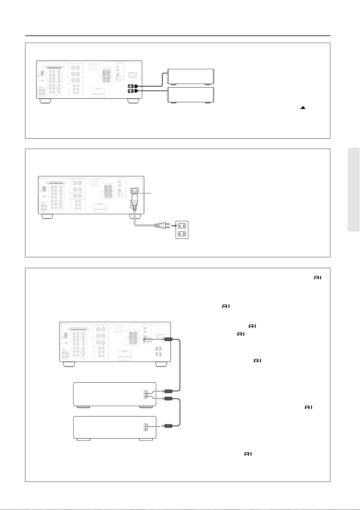
AC outlet connection
You can connect the power cord from another
AC I NLET
audio device to the rear of this receiver.
Since the AC outlets on the unit are a
SWITCHED type outlet, you can use the
STANDBY/ON button to turn on/off the
power to both this receiver and the connected
audio devices.
First turn the POWER switch ON ( ).
ON
Make sure that the total capacity of other components connected to this unit does not exceed
the capacity that is printed on the rear panel.
Connecting a power cable
1. Connect the outlet plug on the included
power cable to the AC INLET on the
DTR-5.
AC I NLET
AC 120V 60Hz
SWITCHED
1
2. Plug-in the other end of the cable to a
wall AC outlet.
Note:
• Do not use any power cable other than the
included cable. The included cable is
designed for use only with the DTR-5. Do
2
not use it for any other device.
• Do not connect or disconnect the outlet plug
from the DTR-5 while the other end is
plugged into the wall AC outlet.
Connections for remote control ( )
You can use the remote controller of this
receiver to operate cassette tape decks and
compact disc players that have Onkyo/Integra
connectors.
DTR-5
DIGITAL INPUT
AVIS
WARNING
RISK OF ELECTRIC SHOCK
RISQUE DE CHOC ELECTRIQUE
DO NOT OPEN
NE PAS OUVRIR
V
L
R
ANTENNA
AM
FM
75
L
R
PHONO
N
I
DVD
I N
VIDEO 3
N
I
VIDEO 2
I
N
VIDEO 1
GND
OUT
(
)
PLAY
MONITOR
I
N
V
OUT
TAPE
SUBWOOFER
OUT
PRE OUT
(
)
REC
L
R
C D
FRONT
SPEAKERS
CENTER
SPEAKER
A
RLR
FRONT
R
SURROUND
R
CENTER
MULT I CHANNEL I NPUT
L
CAUTION: SPEAKER IMPEDANCE
6 OHMS MIN. PER EACH
SPEAKER TERMINAL
L
L
SUB
WOOFER
L
FRONT
SPEAKERS
B
R
L
SURROUND
SPEAKERS
R
AV RECEIVER
MODEL NO. DTR-5
RATING:
AC120V 60Hz 3.9A
2-1, NISSHIN-CHO, NEYAGAWA-SHI,OSAKA,
JAPAN
MANUFACTURED IN MALA
COAXIAL 2
COAXIAL 1
L
R
L
R
YSIA
REMOTE CONTROL
AC I NLET
OPTICAL
AC 120V 60Hz
SWITCHED
TOTAL 120W 1A MAX.
Connect a remote control cable to the connector with the mark.
• An remote control cable equipped with
a 3.5mm (1/8 in.)-diameter miniature twoconductor phone plug comes with every
compact disc player or cassette tape deck
that has an connector.
• Remote control operation is not possible if
only the remote control cable is connected –
the audio connection cables must also be
connected.
CD Player
• This receiver’s remote controller does not
support control of Onkyo turntables.
• If the connecting device has two con-
nectors lined-up vertically or horizontally,
you can use either of them. They both offer
Cassette Tape Deck
the same functionality.
• You can use the remote controller for the
DTR-5 to control a Onkyo/Integra DVD
player or MD recorder that is not connected
via an cable. When you control such a
DVD player or MD recorder, point the
remote controller toward the sensor area of
the DVD player or MD recorder.
9
Page 10
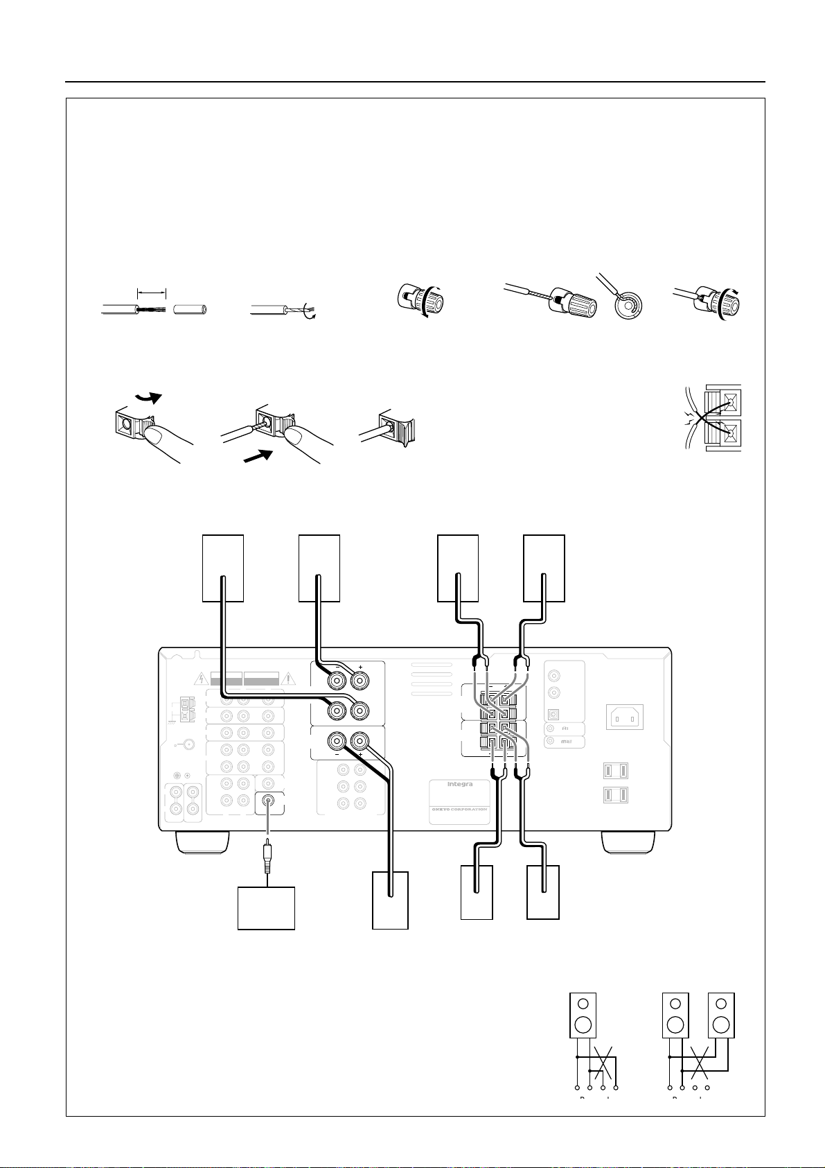
Connecting speakers
• If you want to use the surround effects, connect surround speakers. For the best results, connect a center speaker.
• Use FRONT SPEAKERS B terminals to connect a second pair of front speakers.
• This receiver is designed to produce optimum sound quality when speakers with impedances within the specified ranges are con-
nected. Please check the following information and choose speakers with appropriate impedances for the connections.
FRONT SPEAKERS: A or B: 6 ohms min./speaker
SURROUND SPEAKERS: 6 ohms min./speaker
CENTER SPEAKER: 6 ohms min.
Connecting the speaker cable
1. Twist wire ends very tight.
10 mm
2. Unscrew. 3. Insert wire. 4. Screw.
2. Press down the lever.
ANTENNA
AM
FM
75
GND
L
R
C D
PHONO
3. Insert the wire
into the hole.
Front Speakers A
R ch.
+–+–
WARNING
RISK OF ELECTRIC SHOCK
RISQUE DE CHOC ELECTRIQUE
DO NOT OPEN
L
R
DVD
VIDEO 3
VIDEO 2
VIDEO 1
(
)
PLAY
N
I
TAPE
OUT
(
)
REC
L
R
AVIS
NE PAS OUVRIR
V
I
N
I N
I
N
N
I
OUT
V
MONITOR
OUT
SUBWOOFER
PRE OUT
4. Release the lever
L ch.
L
FRONT
SPEAKERS
A
R
CENTER
SPEAKER
FRONT
R
SURROUND
R
CENTER
MULT I CHANNEL I NPUT
to replace it.
L
R
CAUTION: SPEAKER IMPEDANCE
L
L
SUB
WOOFER
R ch.
6 OHMS MIN. PER EACH
SPEAKER TERMINAL
AV RECEIVER
MODEL NO. DTR-5
RATING:
AC120V 60Hz 3.9A
2-1, NISSHIN-CHO, NEYAGAWA-SHI,OSAKA,
JAPAN
MANUFACTURED IN MALA
NOTE:
To prevent damage to circuitry,
never short-circuit the positive (+)
and negative (–) speaker wire.
Front Speakers B
L ch.
+–+–
DIGITAL INPUT
COAXIAL 2
FRONT
SPEAKERS
B
SURROUND
SPEAKERS
L
R
L
R
L
R
L
R
YSIA
COAXIAL 1
OPTICAL
REMOTE CONTROL
AC I NLET
AC 120V 60Hz
SWITCHED
TOTAL 120W 1A MAX.
NO
10
Active subwoofer
• When you use only one speaker or wish to listen
to monaural (mono) sound, a single speaker
should never be connected in parallel to both the
right and left channel terminals simultaneously.
–+
Center Speaker
+–+–
R ch.
L ch.
Surround Speakers
+––+ +––+
Page 11
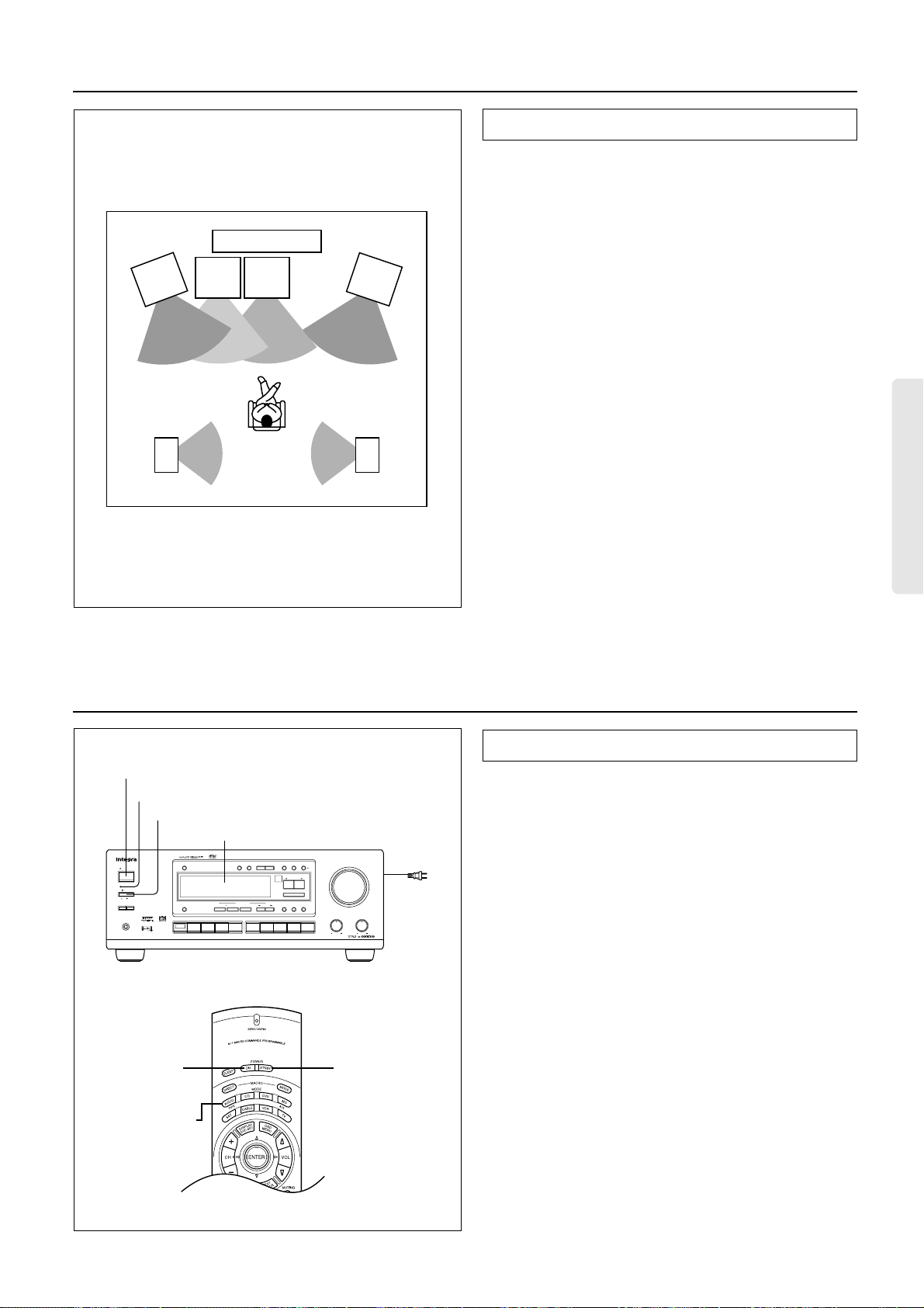
Positioning speakers
TV or Screen
Front
speaker
Left
Surround
speaker
Left
Sub-
woofer
speaker
Center
speaker
Listener
Front
speaker
Right
Surround
speaker
Right
Positioning speakers
Speaker placement plays an important role in the reproduction of
Surround sound. The placement of the speakers varies depending
on the size of the room and the wall coverings used in the room.
The illustration shows an example of a layout for standard speaker
placement. Refer to this example when you position the speakers in
order to experience the best of Surround sound.
Standard speaker placement
For ideal Surround effects, all speakers should be installed. If a
center speaker or subwoofer is not connected, the sound from the
unused channel is properly distributed to the connected speakers in
order to produce the best Surround sound possible.
Front: The left, right, and center speakers should face the seated
listener and be placed at ear level. The center speaker produces a
richer sound image by enhancing the perception of the sound’s
source and movement.
Surround: Place the left and right Surround speakers 1 meter
(3 feet) above the listener’s ear level and facing toward the sides of
the room, making sure that the listener is within the speakers’ dispersion angle. These speakers produce the feel of a moving sound
while creating the sensation of being in the middle of the action.
Subwoofer: Install a subwoofer with a built-in power amplifier for
powerful bass sounds. The placement of the subwoofer does not
affect the final quality of the sound image too much, so you can
install it with the room layout in mind.
Connecting the power
3. STANDBY/ON button
STANDBY indicator
2. POWER switch
Display
STANDBY/ON
STANDBY
POWER
ON
OFF
SPEAKERSAB
PHONES
FM
MUTE /
DIGITAL/
SP / SYS
MODE
ANALOG
SETUP
UPDOWN
DIMMER
DISPLAY
VIDEO 1
CH
MULTI
INPUT
TUNING
MEMORY
LISTENING MODE
/DTS
SURROUND
STEREO
VIDEO 3
VIDEO 2
PRESET / MODE ADJ
DOW NUP
ENTER / SCAN
LATE
NIGHT /
5
CH STEREO
EFFECT
FRONT
DSP
Re -EQ
AM PHONO C
FM
TAPEDVD
MASTER VOLUME
CH LEVEL
MODE
To wall
LFE LEVEL
CONTROL
BASS
D
1.
TREBLE
outlet
Refer to the speaker’s instruction manual for more details.
Connecting the power
• Before you plug in the receiver, confirm that all connections
have been made properly.
• Turning on this receiver’s power may cause a momentary power
surge, which might interfere with other electrical equipment,
such as computers. If this happens, use a wall outlet on a different circuit.
1. Plug the power cord into an AC wall outlet.
2. Press the POWER switch to set the receiver to Standby
mode.
The STANDBY indicator will light up.
3. Press the STANDBY/ON button to turn on the receiver. The
display will light up and the STANDBY indicator will be
turned off.
If you press the STANDBY/ON button, the receiver returns to
Standby mode.
2. POWER ON
button
1. MODE AUDIO
button
2. POWER STNBY
button
Turning the power on from the remote controller:
1. Press the MODE AUDIO button.
2. Press the POWER ON button to turn on the power to the
DTR-5, or press the POWER STNBY button to set the
receiver in standby mode.
• You cannot use the remote controller if the POWER switch on
the receiver is set to OFF.
• Set the volume level to minimum before you turn off the power
to the receiver.
11
Page 12
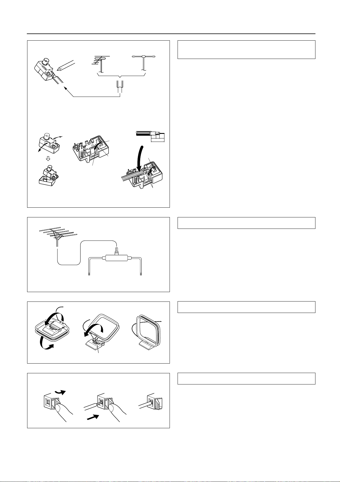
Making antenna connections
Connecting the antenna cable to the 75/300 ohm
antenna adapter (Worldwide models)
Outdoor
antenna
300 ohms
ribbon wire
12 3
Slit B
Wire A
Slit C
Indoor
antenna
✦
✦
✦
✦
✦
✦
✦
6mm3mm6
1
2
✦
✦
✦
✦
15mm
Connecting the 300 ohm ribbon wire:
Loosen the screws and wrap the wire around these screws. Then
tighten the screws with a screwdriver.
Connecting the coaxial cable:
1. With your fingernail or a small screwdriver, press the stoppers
outward and remove the cover.
2. Remove the transformer wire A from slit B and insert it into slit
C.
3. Prepare the coaxial cable as shown in the diagram.
Connect the 75/300 ohm antenna adapter to the coaxial cable.
mm
1 Insert the end of the cable.
2 Clamp it in place with pliers.
4. Re-install the cover.
Directional linkage
type splitter
To DTR-5 To TV (or VCR)
Insert into the hole.
12
Directional Iinkage
Do not use the same antenna for both FM and TV (or VCR) reception since the FM and TV (or VCR) signals can interfere with each
other. If you must use a common FM/TV (or VCR) antenna, use a
directional linkage type splitter.
Assembling the AM loop antenna
Assemble the loop antenna as shown in the illustration.
• Refer to the next page for details on connecting the AM loop
antenna.
Connecting the antenna cable
3
1. Press down the lever.
2. Insert the wire into the hole.
3. Release the lever to replace it.
12
Page 13
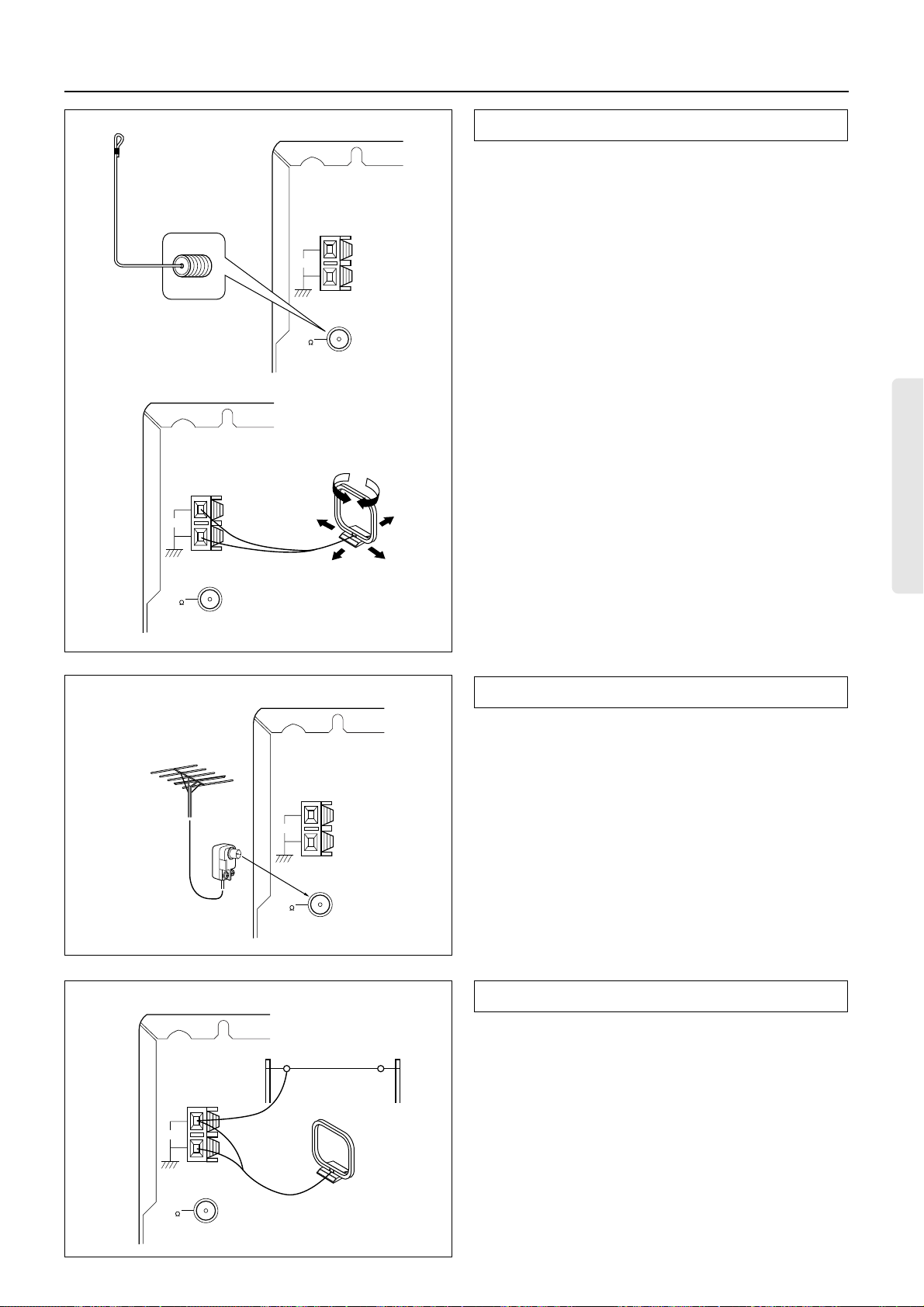
Making antenna connections
ANTENNA
AM
Remove the insulation at the
tip of the cable, and insert the
cable securely, fully to the end
of the exposed tip.
ANTENNA
AM
FM
75
Connecting the included antennas
Connecting the FM indoor antenna:
The FM indoor antenna is for indoor use only. Extend the antenna
and move it in various directions until the clearest signal is
received. Fix it with push pins or similar implements in the position that will cause the least amount of distortion.
If the reception is not very clear with the attached FM indoor
antenna, the use of an outdoor antenna is recommended.
Connecting the AM loop antenna:
The AM loop antenna is for indoor use only. Set it in the direction
and position where you receive the clearest sound. Put it as far
away as possible from the unit, TVs, speaker cables, and power
cords.
When reception is not satisfactory with the attached AM loop
antenna alone, connection of an outdoor antenna is recommended.
FM
75
Connecting an FM outdoor antenna
Please make sure that you follow the considerations below regarding the location.
Keep the antenna away from noise sources (neon signs, busy roads,
etc.).
ANTENNA
It is dangerous to put the antenna close to power lines. Keep it well
away from power lines, transformers, etc.
AM
• To avoid the risk of lightning and electrical shock, grounding is
necessary. Follow item 19 of the “Important Safeguards” on
page 2 when you install the outdoor antenna.
FM
75
Connecting an AM outdoor antenna
The outdoor antenna will be more effective if it is stretched horizontally above a window or outside.
ANTENNA
AM
FM
75
Outdoor
antenna
• Do not remove the AM loop antenna.
• To avoid the risk of lightning and electrical shock, grounding is
necessary. Follow item 19 of the “Important Safeguards” on
page 2 when you install the outdoor antenna.
13
Page 14
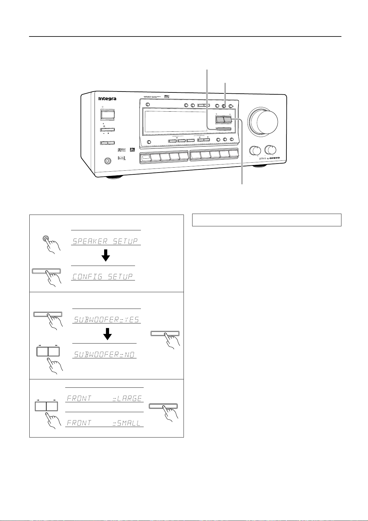
Speaker setup
Follow the steps below before you start operating the unit.
ENTER/SCAN button
SP SYS/SETUP button
FM
MUTE
/DTS
SURROUND
ID
V
/
M
E
M
O
RY
MODE
E
D
O
M
G
N
I
N
E
T
IS
L
O
E
R
E
T
S
H
C
5
P
A
T
3
O
E
S
T
A
N
D
B
Y
/O
N
Y
B
D
N
A
T
S
POWER
OFF
ON
B
S
PEAKER
S
A
PHONES
DIMMER
O
E
R
E
T
DISPLAY
H
C
I
T
L
U
M
T
U
P
IN
S
2
O
E
ID
V
1
O
E
ID
V
D
V
D
D
IG
IT
A
L
/
S
P
/
S
Y
O
W
N
T
UN
ING
P
S
D
M
F
E
S
U
PD
A
N
A
L
O
G
S
E
T
U
P
C
H
L
E
V
E
L
M
O
D
E
P
R
E
S
E
T
/
M
O
D
E
A
D
J
N
W
O
D
U
P
N
A
C
S
/
R
E
T
N
E
LEVEL
LFE
/
NIGHT
LATE
-EQ
Re
CONTROL
EFFECT
T
N
FRO
D
C
O
N
O
H
P
M
A
MASTER VOLUME
BASS
TREBLE
1
SP / SYS
SETUP
ENTER / SCAN
2
ENTER / SCAN
PRESET / MODE ADJ
DOW NUP
3
PRESET / MODE ADJ
DOW NUP
or
ENTER / SCAN
ENTER / SCAN
PRESET/MODE ADJ √/® button
Setting the CONFIG parameters
Set whether a speaker is used or not, and set the size of the connected speakers.
1. Press the buttons in the following sequence to display
“CONFIG SETUP.”
2. Set whether a subwoofer is used or not.
When you press the ENTER/SCAN button while “CONFIG
SETUP” is displayed, the current setting (“SUBWOOFER
YES” or “NO”) appears. Press the PRESET/MODE ADJ
buttons to select “YES” or “NO.”
YES: When the subwoofer is connected.
NO: When the subwoofer is not connected.
Select whichever appropriate and press the ENTER/SCAN button.
3. Select the size of the front speakers.
If you have set the subwoofer parameter to “NO” in step 2, proceed to step 4. (At this time, the front speaker parameter automatically sets to LARGE.)
Pressing the PRESET/MODE ADJ
√
/
®
buttons toggles
between “LARGE” and “SMALL.”
LARGE: When large speakers are used as the front speakers.
SMALL: When small speakers are used as the front speakers.
Select whichever appropriate and press the ENTER/SCAN button.
√
/
®
14
Page 15
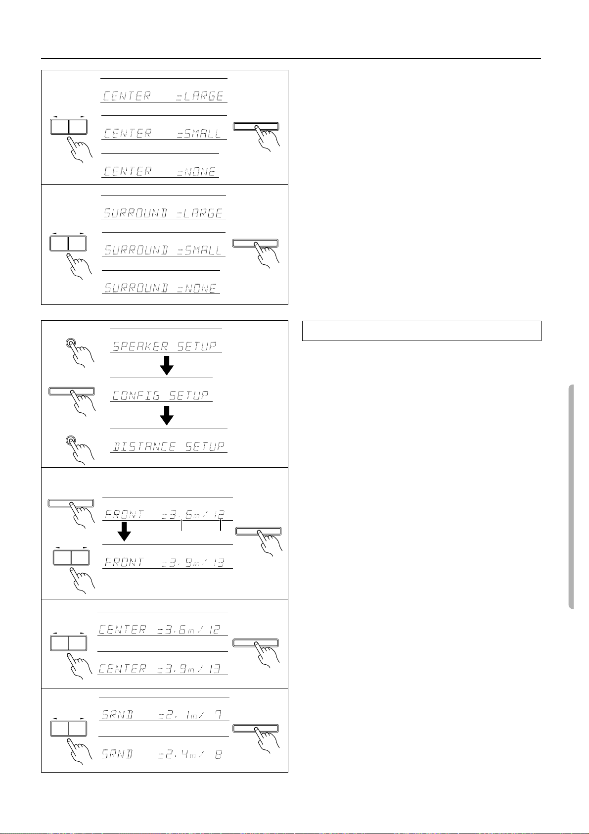
Speaker setup
4
PRESET / MODE ADJ
DOW NUP
5
PRESET / MODE ADJ
DOW NUP
4. Select the size of the center speaker.
Pressing the PRESET/MODE ADJ
√
/
®
buttons switches
among “LARGE,” “SMALL,” and “NONE.”
or
ENTER / SCAN
Note:
If you have selected “SMALL” for the front speakers, you can
select only “SMALL” or “NONE” for the center speaker.
LARGE: When a large speaker is used as the center speaker.
or
SMALL: When a small speaker is used as the center speaker.
NONE: A center speaker is not connected.
Select whichever appropriate and press the ENTER/SCAN button.
5. Select the size of the surround speakers.
Note:
If you have selected “SMALL” for the front speaker, you can
or
ENTER / SCAN
select only “SMALL” or “NONE” for the surround speakers.
LARGE: When large speakers are used as the surround
speaker.
SMALL: When small speakers are used as the surround
or
speaker.
NONE: Surround speakers are not connected.
Select whichever appropriate and press the ENTER/SCAN button.
This completes the CONFIG SETUP settings.
SP / SYS
SETUP
1
ENTER / SCAN
SP / SYS
SETUP
2
ENTER / SCAN
PRESET / MODE ADJ
DOW NUP
3
PRESET / MODE ADJ
DOW NUP
meter feet
Setting the DISTANCE parameters
Set the distance from the listening position to each speaker.
1. Press the buttons in the following sequence to display “DISTANCE SETUP.”
2. Set the distance to the front speakers.
Pressing the ENTER/SCAN button while “DISTANCE
SETUP” is displayed will cause the “FRONT” distance parameter to appear.
Press the PRESET/MODE ADJ
distance value. You can set the distance in the range of 1feet
(0.3m) – 30feet (0.9m) in 1feet (0.3m) steps.
Press the ENTER/SCAN button to confirm the value.
3. Set the distance to the center speaker.
Press the PRESET/MODE ADJ
distance value.
f t
ENTER / SCAN
Press the ENTER/SCAN button to confirm the value.
Note:
If you have selected “NONE” for the center speaker of the
CONFIG parameter, skip this note.
f t
You cannot set a larger value than the front speaker distance.
You cannot set a smaller value than the front speaker distance
deducted by 5feet (1.5m).
4. Set the distance to the surround speakers.
Press the PRESET/MODE ADJ
distance value and press the ENTER/SCAN button.
f t
ENTER / SCAN
Note:
If you have selected “NONE” for the surround speaker of the
CONFIG parameter, skip this note.
f t
You cannot set a larger value than the front speaker distance.
You cannot set a smaller value than the front speaker distance
deducted by 15feet (4.5m).
√
/
®
buttons to set the closest
√
/
®
buttons to set the closest
√
/
®
buttons to set the closest
4
PRESET / MODE ADJ
DOW NUP
f t
This completes the DISTANCE settings.
ENTER / SCAN
f t
15
Page 16
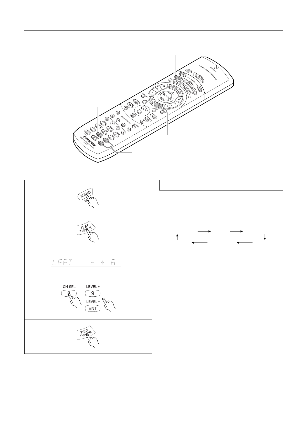
Speaker setup
3. CH SEL button
1. MODE AUDIO button
3. LEVEL +/– button
2. TEST button
1
2
dB
3
4
Test T one
Use the remote controller and produce the test tone to adjust the
level of the connected speakers.
1. Press the MODE AUDIO button.
2. Press the TEST button.
Each speaker produces the test tone (pink noise) in the following order:
LEFT (Front L ch)
SUBWOOFER
No sound will be output from the speakers for which the CONFIG parameters is set to NO or NONE.
3. To adjust the level of each speaker, press the CH SEL button
to select a speaker and press the LEVEL +/– buttons to raise
or lower the level.
The test tone should sound at the same level when you hear it in
your listening position. You can adjust the level in the range
between –12dB and +12dB.
If the speaker level is set to +1dB or higher, the maximum level
indicated on the display will change if you raise the volume
level. Refer to “About volume (VOLUME)” on page 20 for
more information.
4. Press the TEST button to complete adjustment.
Note
The Test Tone function is not available when SPEAKERS B is
•
selected, when the headphones are connected, or when MULTICH INPUT is selected.
CENTER
(Center ch)
L-SURROUND
RIGHT (Front R ch)
R-SURROUND
Using the Test Tone function on the main unit
1. Press the SP/SYS SETUP button.
2. Press the ENTER/SCAN button while “SPEAKER SETUP” appears on the display.
3. Press the SP/SYS SETUP button twice while “CONFIG SETUP” appears on the display.
4. Press the ENTER/SCAN button while “LEVEL SETUP” appears on the display.
Each speaker produces the test tone in the order described above.
5. Use the PRESET MODE ADJ
6. Press the SP/SYS SETUP to complete adjustment.
√
/
®
buttons to adjust the level.
16
Page 17
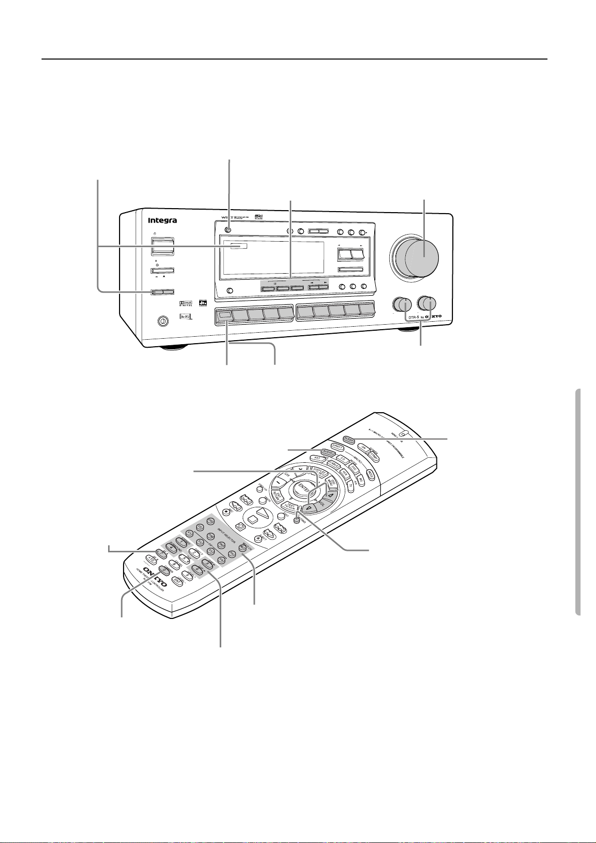
Selecting a sound source
Follow the steps below to select a device to play the sound source.
2. Make sure that the SPEAKERS
A indicator is lit on the display.
If it is not lit, press the
SPEAKERS A button.
(Refer to the “Speakers selector”
section on the page 20 for more
details.)
S
T
A
N
D
B
Y
/O
Y
B
D
N
A
T
S
POWER
OFF
ON
RS
SPEAKE
A
PHONES
DIMMER button
Use this button to change
the brightness of the
display (normal or dim).
N
B
DIMMER
DISPLAY
I
T
L
U
M
P
IN
4. LISTENING MODE
Select a Listening mode.
(Refer to page 21)
FM
MUTE
M
EM
O
R
Y
MODE
E
E
D
D
O
O
M
M
G
G
N
N
I
I
N
N
E
E
T
T
IS
IS
L
L
E
E
R
R
E
E
T
T
S
S
H
H
C
C
5
5
SURROUND
SURROUND
/DTS
/DTS
O
O
E
E
R
R
E
E
T
T
S
S
3
O
E
ID
V
2
O
E
ID
V
1
O
E
ID
V
D
V
D
H
C
T
U
/
D
O
W
N
TUNING
P
P
S
S
D
D
O
O
M
F
E
P
A
T
5. Adjust the volume to an appropriate level.
These controls allow you to adjust the volume of the
Front, Center, Surround speakers and subwoofer
simultaneously. Turning the control clockwise
increases the volume level. Turning the control
counter-clockwise decreases the volume level.
(Refer to page 20 for more details.)
D
IG
I
T
A
L
/
S
P
/
S
Y
S
U
P
A
N
A
L
O
G
S
E
T
U
P
C
H
L
E
V
E
L
M
O
D
P
R
E
S
E
T
/
M
O
D
E
A
D
J
N
W
O
D
U
P
N
A
C
/S
R
E
T
N
E
LEVEL
LFE
/
NIGHT
LATE
-EQ
Re
L
ONTRO
C
EFFECT
NT
O
FR
D
C
O
N
O
H
P
M
A
MASTER VOLUME
E
TREBLE
BASS
1. Press the desired input selector button or
MULTI CH INPUT button.
The selected source name appears on the display. If
you have selected DVD, CD, VIDEO 1, VIDEO 2,
VIDEO 3, or TAPE, see page 18. Refer to page 19
for more information on MULTI CH INPUT.
1. Press the MODE AUDIO button
5. VOLUME button (qup/udown)
Use this button to adjust the
volume level.
2. SP A button
Use this button
to select Speaker A.
DIMMER button
Use this button to change the brightness
of the display (normal or dim).
4. Select a Listening mode. (Refer to page 21)
3. Start playing the selected input
source.
Follow the operating instructions
for the source device.
MUTING button
This button mutes the sound temporarily.
(Refer to page 20 for more details.)
3. INPUT SELECTOR button
Use this button to select a desired sound source.
(V4 button is not used for this DTR-5.)
6. Use the bass, treble
controls to adjust the tone.
(Refer to page 20 for more
details.)
SLEEP button
This button allows you
to set the sleep timer.
(Refer to page 20 for
more details.)
Note:
If you hear no sound from the speakers, check the following items:
• Make sure that all devices and speakers are connected correctly and securely.
• The sound is muted when the “MUTING” is on the display. Press the MUTING button on the remote controller to cancel the mute func-
tion.
• When you select a source that is connected to the DIGITAL INPUT jacks on the rear panel. Check to see if the audio (digital or analog)
selection is correct (when DVD, CD, VIDEO 1-3, or TAPE is selected) (refer to page 18).
• If you have selected MULTI CH INPUT, you need to adjust the level of each speaker (refer to page 19).
17
Page 18
Selecting a sound source
1
2
3
DVD
DIGITAL/
ANALOG
PRESET / MODE ADJ
DOW NUP
DVD Player
DTR-5
DIGITAL INPUT
COAXIAL 2
COAXIAL 1
OPTICAL
Audio (digital or analog) selection
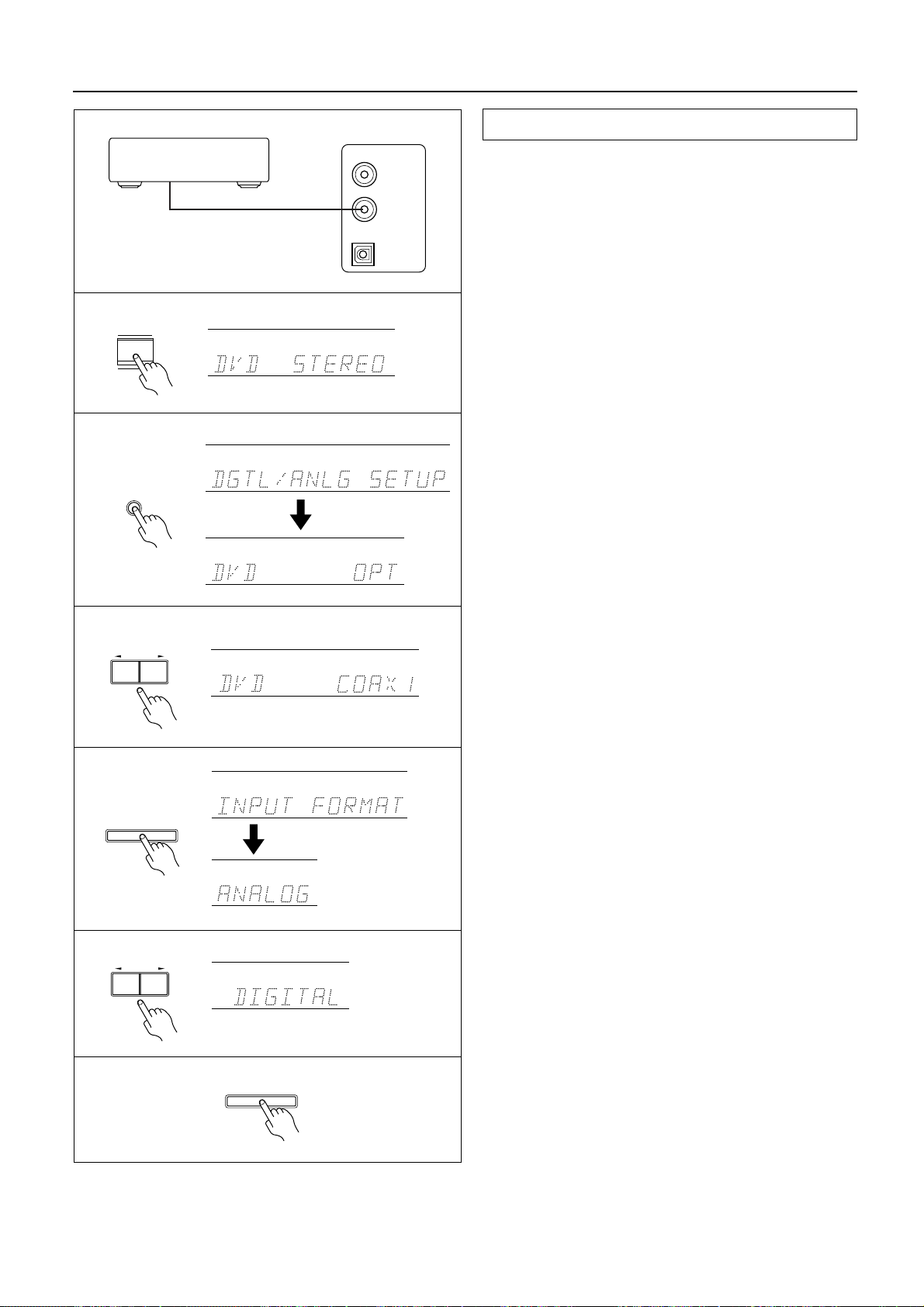
You can select either digital audio or analog audio for DVD, CD,
VIDEO 1, VIDEO 2, VIDEO 3, or TAPE input. The default setting
is ANALOG. Change the setting according to the connection and
playback source.
Assume that you have connected a D VD player to the COAXIAL 1
connector.
1. Use the INPUT button to select “DVD.”
2. Press the DIGITAL/ANALOG button to set digital input.
“DGTL/ANLG SETUP” appears, followed by the current setting (“DVD =” OPT, COAX1, COAX2, or ANALOG).
3. Press “PRESET/MODE ADJ
4. Press the ENTER/SCAN button.
“INPUT FORMAT” appears, followed by the current setting
(“FORMAT =” DIGITAL, or ANALOG).
5. Press “PRESET/MODE ADJ
6. Press the ENTER/SCAN button.
Tip:
You may play analog audio while digital input is selected if you
select “ANALOG” in Step 5.
Note:
You cannot select “FORMAT” as described in Step 4 if you
•
select “ANALOG” in Step 3.
If you wish to listen to analog sound, select “ ANALOG” in Step
•
5. (Digital input remains assigned.)
You can assign digital input to DVD, VIDEO 1, VIDEO 2,
•
VIDEO 3, TAPE, and CD.
√
/
®
” to select COAX1.
√
/
®
” to select DIGITAL.
4
5
6
ENTER / SCAN
PRESET / MODE ADJ
DOW NUP
ENTER / SCAN
Even when the digital inputs are used, the analog connecting cables
must be left in place. Otherwise, the audio output from TAPE OUT
and VIDEO 1 will not work. (See page 7.)
Warning:
•
Do not play CD-ROM discs that contain computer data as they
may damage the speakers when the sound is amplified by the
receiver.
18
Page 19
Selecting a sound source
1
2
4-1
When Multi channel input is selected as a source
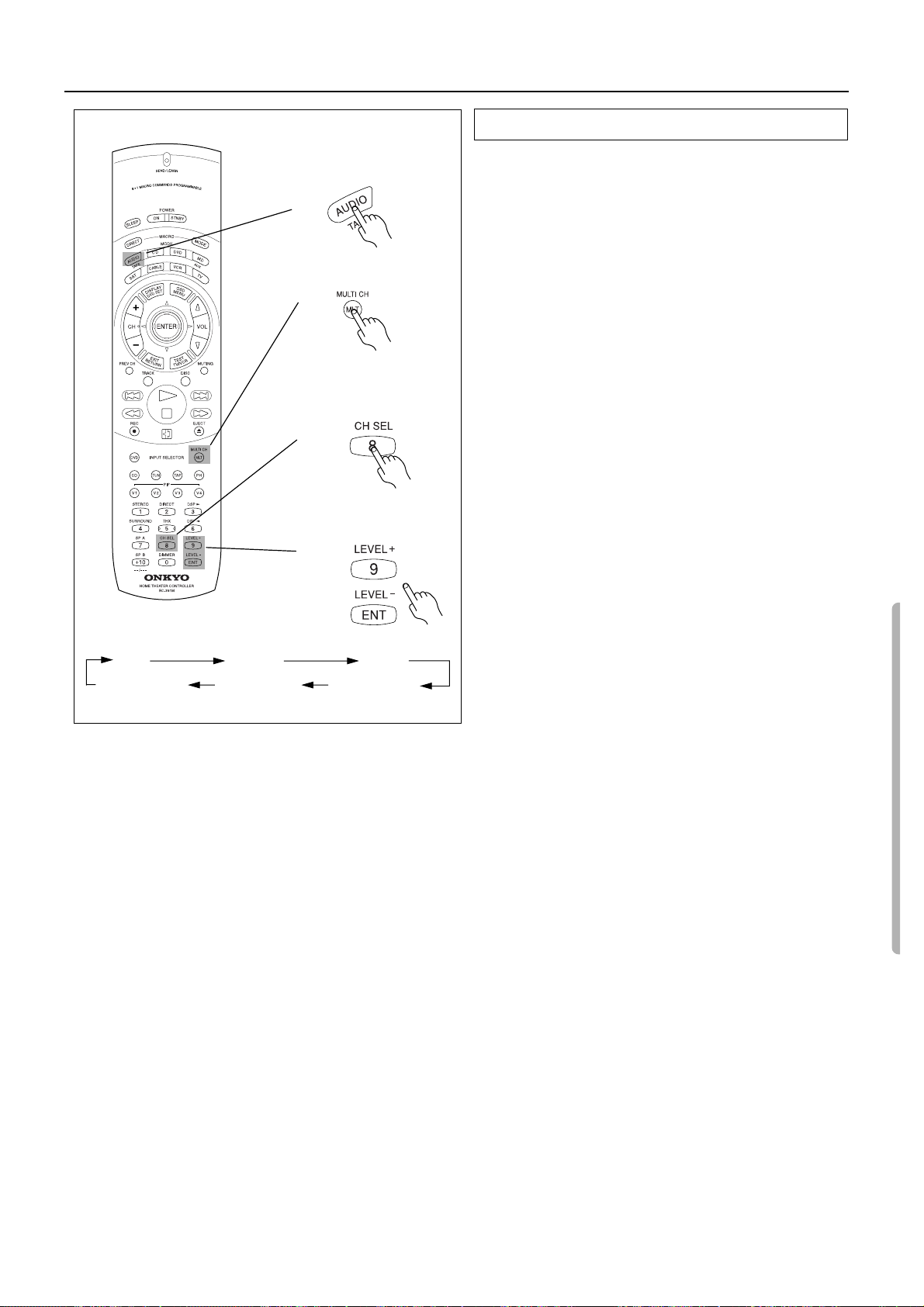
Follow the steps below to adjust the level of each speaker if you
have selected MULTI CH INPUT.
1. Press MODE AUDIO button on the remote controller.
2. Press MLT button on the remote controller.
You cannot select any listening mode.
3. Play the device connected to the MULTI CHANNEL INPUT
jack.
4. Adjust the volume level of each speaker.
4-1. Press the CH SEL button to select the desired speakers.
4-2. Use the LEVEL +/– button to change the volume level of
the speakers.
You can adjust the volume level of each speaker individually. Adjust the level while listening to the sound in the listening position.
You can adjust the level of the front, center, and surround
speakers in the range between –12dB and +12dB.
You can adjust the subwoofer level in the range between –
30dB and +12dB.
LEFT
4-2
CENTER RIGHT
L-SURROUND
R-SURROUNDSUBWOOFER
Note
•
Adjusting the volume level of each speaker for the MULTI CH
INPUT source does not affect the speaker level adjusted by the
Test Tone function, and vice versa.
If the speaker level is set to +1dB or higher, the maximum level
•
indicated on the display will change if you raise the volume
level. Refer to “About volume (VOLUME)” on page 20 for
more information.
19
Page 20
Selecting a sound source
Speakers selector (SPEAKERS A, B)
SPEAKERS A: This button turns on or off the speakers connected
to the FRONT SPEAKERS A, CENTER SPEAKER, SURROUND
SPEAKERS and SUBWOOFER terminals.
When you select Surround mode or Multi CH INPUT, be sure to
turn on SPEAKERS A.
When the speakers are turned on, the SPEAKERS A indicator
lights up.
SPEAKERS B: This button turns on or off the speakers connected
to the FRONT SPEAKERS B terminals.
When the speakers are turned on, the SPEAKERS B indicator
lights up.
Note:
You cannot select Surround sound when you are using SPEAKERS
B. If you select SPEAKERS B while Surround sound is selected,
Surround mode will be automatically canceled.
Adjusting the tone (BASS, TREBLE)
Treble and bass adjustment is effective only for the Front speakers
and headphones.
BASS: Boosts or cuts the bass response.
TREBLE: Boosts or cuts the treble response.
Listening through headphones (PHONES)
You can connect stereo headphones to the PHONES jack using a
standard stereo plug.
If you connect headphones, the unit will enter STEREO mode
automatically, and no sound will be produced from the speakers. If
you have selected MULTI CH INPUT, you will hear sound only
from the FRONT L and R channels.
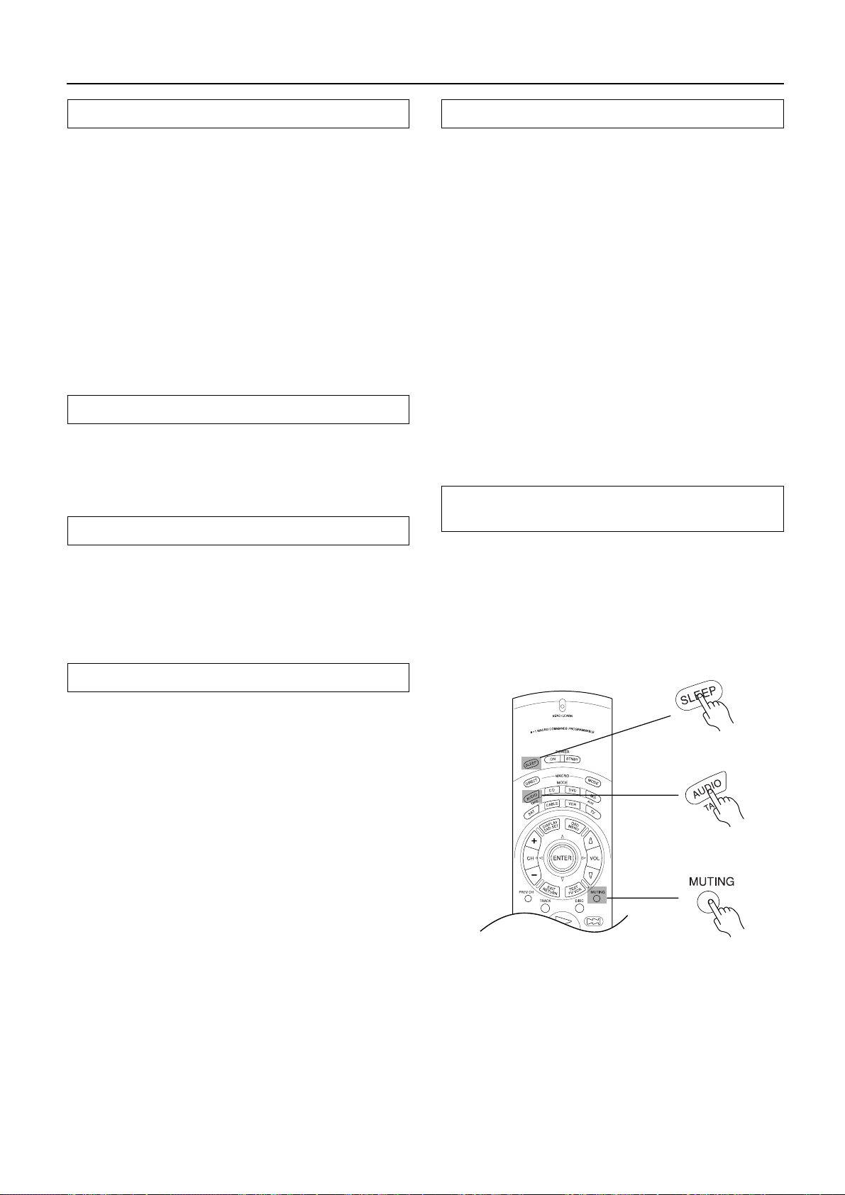
Sleep function (Remote controller only)
The sleep timer can turn off the power to the system after a specified time period.
To set up this function, use the remote controller supplied with this
receiver.
1. Start playing the source you would like to listen to (CD,
tape, or radio broadcast).
2. Press the MODE AUDIO button.
3. Press the SLEEP button repeatedly to set the duration of
time after which you want the system to turn off.
The longest timer value you can set is 90 minutes. Pressing the
SLEEP button each time reduces the time value in 10-minute increments.
When the specified time comes, the power will be switched off
automatically.
Disabling the Sleep function
Press the SLEEP button until it returns to the selected input source
name.
or
The timer setting will be cancelled if you turn off the power to the unit.
Temporary muting (MUTING)
(Remote controller only)
Press the MUTING button.
The “MUTING” appears on the display and the sound from the
speakers or headphones will be switched off by the receiv er’s audio
muting circuits.
To cancel,
• press the MUTING button again, or
• turn the power off, then turn it on again.
About volume (VOLUME)
You have the option of displaying your volume settings either of
two ways:
•
ABSOLUTE — on a scale of MIN (0: no sound) to MAX (80:
extremely sound);
or
•
RELATIVE — on a scale which is measured “plus or minus,”
relative to the calibrated reference volume.
With either settings, the volume level changes in the same increment.
ABSOLUTE: MIN, 1, 2, 3, 4, ......., 77, 78, 79, MAX
RELATIVE: – ∞ , –61, –60, –59, ......., +16, +17, +18 (dB)
1. Press the SP/SYS SETUP button twice.
“VOLUME DISPLAY” appears.
2. Press the ENTER/SCAN button.
“VOLUME=ABSOLUTE or RELATIVE” appears.
3. Press “PRESET/MODE ADJ
display.
4. Press the ENTER/SCAN button.
•
If the speaker level is set to +1dB or higher, the maximum level
indicated on the display will change if you raise the volume level.
Refer to the following sections for more information on adjusting
the speaker level:
“Test Tone (Remote controller only)” on page 16.
“When Multi channel input is selected as a source” on page 19.
√
/
®
” to select the desired
20
Page 21
Using Listening Mode
Before Using Listening Mode
Listening Modes
The DTR-5’s surround sound enables you to enjoy the presence of
a movie theater or concert hall in your room.
Before using a listening mode, make sure the Speaker Setup
parameters have been set (refer to page 14). Once the parameters
have been set, it is not necessary to set them again.
The configuration of the speakers are very important for the surround sound. Refer to “connecting speakers” on page 10.
DOLBY DIGITAL Surround,
DTS (Digital Theater System) Surround
This 5.1-channel digital surround format enables you to individually record and play five full-range (20Hz–20kHz) channels (left
and right front, center, two surround channels) plus an LFE channel (Low Frequency Effect) for the low-range effect sound. It will
create a realistic sound that could be heard in the theaters and concert halls.
DOLBY DIGITAL: Select this option when you play a DVD video
that has a mark.
DTS: Select this option when you play a DVD player , laser disc, or
CD that has a mark.
DIGITAL
DOLBY PRO LOGIC
This surround format consists of four channels (left and right front,
center, and monaural surround channels) and emphasizes the center channel. This format is very effective for panning music, conversation, and three-dimensional sound movement output from
three front channels. It also simulates the atmosphere and surround
effects of the sound reflected from the side and rear walls of the
theater. Select this option when you play a VHS, VHS Hi-Fi, laser
disc, or DVD video that has a mark.
Integra’s listening modes
The DTR-5 offers the following special Integra listening modes for
the sources other than Dolby Digital and DTS sounds.
ORCHESTRA: This mode is suitable for classics and opera
music. The center channel is cut and the surround channels are
emphasized to widen the stereo image. It will simulate a natural
reverberation that can be created in a large hall.
UNPLUGGED: This mode is suitable for acoustic instrumental
sounds, vocals, and jazz music. By emphasizing the front stereo
image, it will simulate the acoustics in front of the stage.
STUDIO-MIX: This mode is suitable for rock and popular
music. Lively sounds with a powerful acoustic image will make
you feel as if you are in a club.
TV LOGIC: This mode offers a realistic acoustics of a TV program being aired in the TV studio. It enhances the entire surround sound and clarity of conversation.
5CH STEREO: This mode is useful for background music.
The front and surround channels will create a stereo image.
DOLBY SURROUND
• A system with L/R front and center speakers
The following modes are available:
DOLBY 3STEREO
The surround channel sound is output from the left and right
front speakers.
STEREO
This is a normal stereo mode. Surround mode is cancelled.
• A system with L/R front speakers
The following mode is available:
STEREO
This is a normal stereo mode.
Notes on DTS
1. If you play a CD or LD that supports DTS when the “ANALOG” setting is selected on the DTR-5, the DTS encoded signal
will not be decoded and noise will be output. This noise could
damage the amplifier and speakers. Therefore, be sure to select
“DIGITAL” and use the digital input jacks (OPTICAL/COAXIAL) to connect the DTS source. (Refer to “Audio (digital or
analog) selection” on page 18.)
2. If you play a CD or LD that supports DTS when the “DIGITAL”
setting is selected, you may hear a noise for a short while until the
DTS decoder recognizes the DTS encoded signal and starts operating. This is not a malfunction.
3. If you press the PAUSE or SKIP button on the player while playing a DTS source, a short noise may be heard. This is not a malfunction.
4. The DTS indicator on the DTR-5 lights up while it plays the DTS
source. When playback concludes and the DTS signal transmission stops, the DTR-5 remains in DTS mode and the DTS indicator remains lit. This prevents noise when you operate the PAUSE
or SKIP button on the player. Therefore, if the source switches
from the DTS signal to the PCM signal immediately, the PCM
signal may not be played. In this case, stop the playback of the
source on the player for about three seconds, then resume playback.
5. Some CD players and LD players may be unable to play DTS
sources correctly even if you connect the player to the DTR-5
digitally. This is because the digital signal has been processed
(such as the output level, sampling frequency, frequency
response, etc.), and the DTR-5 cannot recognize the signal as
DTS data. Therefore, you may hear noise when you play a DTS
source while processing the signal.
6. The Rec Out jacks of the DTR-5 output analog audio. Do not
record CDs or LDs that support DTS using these jacks. Otherwise, you will record a DTS encoded signal as noise.
STEREO
Select this mode when you do not wish to use the surround mode.
All input sound is output from the front speakers.
21
Page 22

Using Listening Mode
3. Use these buttons to
set the Listening mode
parameters.
(Refer to page 23).
FM
MUTE
/DTS
/DTS
SURROUND
SURROUND
V
/
M
EMO
R
Y
MODE
E
E
D
D
O
O
M
M
G
G
IN
IN
N
N
E
E
T
T
S
S
I
I
L
L
O
O
E
E
R
R
E
E
T
T
S
S
H
H
C
C
5
5
P
A
T
3
O
E
ID
S
T
A
N
D
B
Y/ON
Y
B
D
N
A
T
S
POWER
OFF
ON
B
S
EAKER
SP
A
PHONES
DIMMER
O
O
E
E
R
R
E
E
T
T
S
DISPLAY
H
C
I
T
L
U
M
T
U
P
IN
S
2
O
E
ID
V
1
O
E
ID
V
D
V
D
D
IG
IT
A
L
/
S
P
/
S
Y
O
W
N
TU
NING
P
P
S
S
D
D
M
F
E
S
U
PD
A
N
A
L
O
G
S
E
T
U
P
C
H
L
E
V
E
L
M
O
D
P
R
E
S
E
T
/
M
O
D
E
A
D
J
N
W
O
D
U
P
N
A
C
/S
R
E
T
N
E
L
L
LEVE
LEVE
LFE
LFE
/
/
NIGHT
NIGHT
LATE
LATE
-EQ
-EQ
Re
Re
CONTROL
CONTROL
T
T
FEC
FEC
EF
EF
NT
NT
FRO
FRO
D
C
O
N
O
H
P
M
A
MASTER VOLUME
E
TREBLE
BASS
2. LISTENING MODE buttons
These button allow you to select a
1. Input selector buttons
Select the desired input source.
VOLUME knob
Use this knob to adjust
the volume level.
listening mode.
VOL button (qup/udown)
Use this button to adjust the volume level.
1. Press the MODE
AUDIO button
CH SEL/LEVEL+/– buttons
2. INPUT SELECTOR buttons
Select the desired input source.
3. Listening mode button
These buttons allow you to select a Surround mode.
1
VIDEO 3
MULTI
INPUT
DVD
CH
VIDEO 1
VIDEO 2
Using Listening Mode
1. Press one of the INPUT SELECTOR buttons to select the
desired sound source.
2. Use the LISTENING MODE buttons to select the desired
Listening mode.
TAPE
FM
AM PHONO C
D
STEREO: Press this button to listen to a normal stereo audio.
/DTS SURROUND: Press this button when you wish to
play Dolby ProLogic, Dolby Digital, or DTS Surround sound.
5CH STEREO: Press this button to play 5-ch stereo sound (see
page 21).
DSP √/®: Press this button repeatedly to select the desired
2
LISTENING MODE
/DTS SURROUND
STEREO
5
CH STEREO
DSP
Listening mode. Each option appears in the following sequence:
STEREO /DTS SURROUND
5ch STEREO
ORCHESTRA
UNPLUGGEDSTUDIO-MIX TV LOGIC
3. Play the selected source.
22
Follow the steps below to make adjustment to the speaker level
set by the Test Tone.
1. Press the MODE AUDIO button.
2. Press the CH SEL button to select a speaker.
3. Press the LEVEL +/– buttons to adjust the level.
Page 23
Using Listening Mode
Main unit operation:
1. Press the CH LEVEL button.
2. Press the PRESET/MODE ADJ √/® buttons to adjust the
level.
3. Press the ENTER/SCAN button to select a speaker.
You can adjust the level in the range of –12dB to +12dB.
You cannot select a speaker if the CONFIG parameter of the
speaker is set to NO or NONE.
If the speaker level is set to +1dB or higher, the maximum level
indicated on the display will change if you raise the volume
level. Refer to “About volume (VOLUME)”on page 20 for more
information.
When you turn off the power, the level will be reset to the original level (the value you set using the test tone).
When you press the TEST button after you set the lev el, the cur rent level will be used as the value set via the test tone.
Setting the Listening mode parameters
The following parameters are available for each Listening mode.
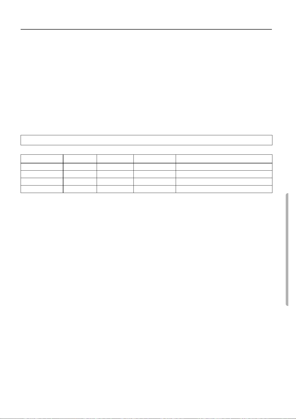
Dolby Digital DTS Surround Dolby Pro Logic Orchestra, Unplugged, Studio-Mix, TV Logic
LATE NIGHT ❍
FRONT EFFECT
Re-EQ
LFE level control
—— — ❍
❍❍ ❍
❍❍
—— —
Note:
• Select a digital input to play Dolby digital or DTS sound
sources. (See page 18.)
• You cannot select Orchestra, Unplugged, Studio-Mix, TV
Logic, or 5CH Stereo if you have selected a Dolby digital or
DTS surround source.
• To play a Dolby digital or DTS Surround source, you need to
connect the sound source using the digital input connector.
• When you play the Dolby Digital or DTS Surround source, the
DTR-5 automatically enters Dolby Digital Surround (stereo) or
DTS Surround (stereo) mode respectively.
—
——
LATE NIGHT
If you play a movie at a low volume at night, set this parameter to
“ON” to narrow the dynamic range of the sound to make it easier to
hear.
The Late Night function works only with source material that contains necessary Dolby Digital information.
Note:
• The Late Night effect is determined by each Dolby Digital
sound. Some sounds may produce no or little effect.
• The Late Night function is effective only on the Dolby Digital
sound.
While the Dolby Digital sound is playing, press the LATE NIGHT/
FRONT EFFECT button. The current setting appears on the display. (LATE NIGHT=ON or OFF)
Pressing the LATE NIGHT/FRONT EFFECT button repeatedly
will toggle between ON and OFF.
FRONT EFFECT
Some live recordings contain acoustic reverberation. When you
play these sources, more reverberation will be applied by the DSP,
creating too much reverb effects and the sound loses its frame or
presence. In this case, set FRONT EFFECT to OFF. No reverberation from the DSP will be applied to the sound output from three
front channels, and the sound source will be played as it is without
any further reverberation.
Note:
The Front Effect function is effective only on the Orchestra,
Unplugged, Studio-Mix, and TV Logic sound.
While Orchestra, Unplugged, Studio-Mix, or TV Logic is selected
for Listening mode, press the LATE NIGHT/FRONT EFFECT button. The current setting appears on the display . (FRT EFFECT=ON
or OFF)
Pressing the LATE NIGHT/FRONT EFFECT button repeatedly
will toggle between ON and OFF.
Re-EQ
Cinema Re-Equalization
Re-Equalization takes the edginess or “brightness” out of your
home cinema sound, compensating for the fact that sound mixed
for theaters will sound too bright when played back through speakers in the home environment.
While the Dolby ProLogic Surround, Dolby Digital Surround, or
DTS Surround sound is playing, press the Re-EQ button. The current setting appears on the display. (RE-EQ=ON or OFF)
Pressing the Re-EQ button repeatedly will toggle between ON and
OFF.
Note:
The Re-EQ function is effective on the Dolby ProLogic Surround,
Dolby Digital Surround, and DTS Surround sound.
LFE (Low Frequency Effect) Level Control
This control function enables you to adjust the level of LFE in the
Dolby Digital/DTS Surround sound.
Note:
The LFE Level Control function is effective only on the Dolby
Digital/DTS Surround sound.
Dolby Digital sound:
Press the LFE LEVEL CONTROL button repeatedly to select 0dB,
–10dB, or –00dB (–∞). “0dB” is recommended. If the low range
sounds too loud for your taste, select 10dB or –00dB (–∞).
DTS sound:
Press the LFE LEVEL CONTROL button repeatedly to select
+10dB, 0dB, or –00dB (–∞). “+10dB” is recommended for
cinema sound sources. If the low range sounds too loud for
your taste, select 0dB or –00dB (–∞). “0dB” is recommended
for music sound source. If the low range sounds too loud for
your taste, select –00dB (–∞).
23
Page 24
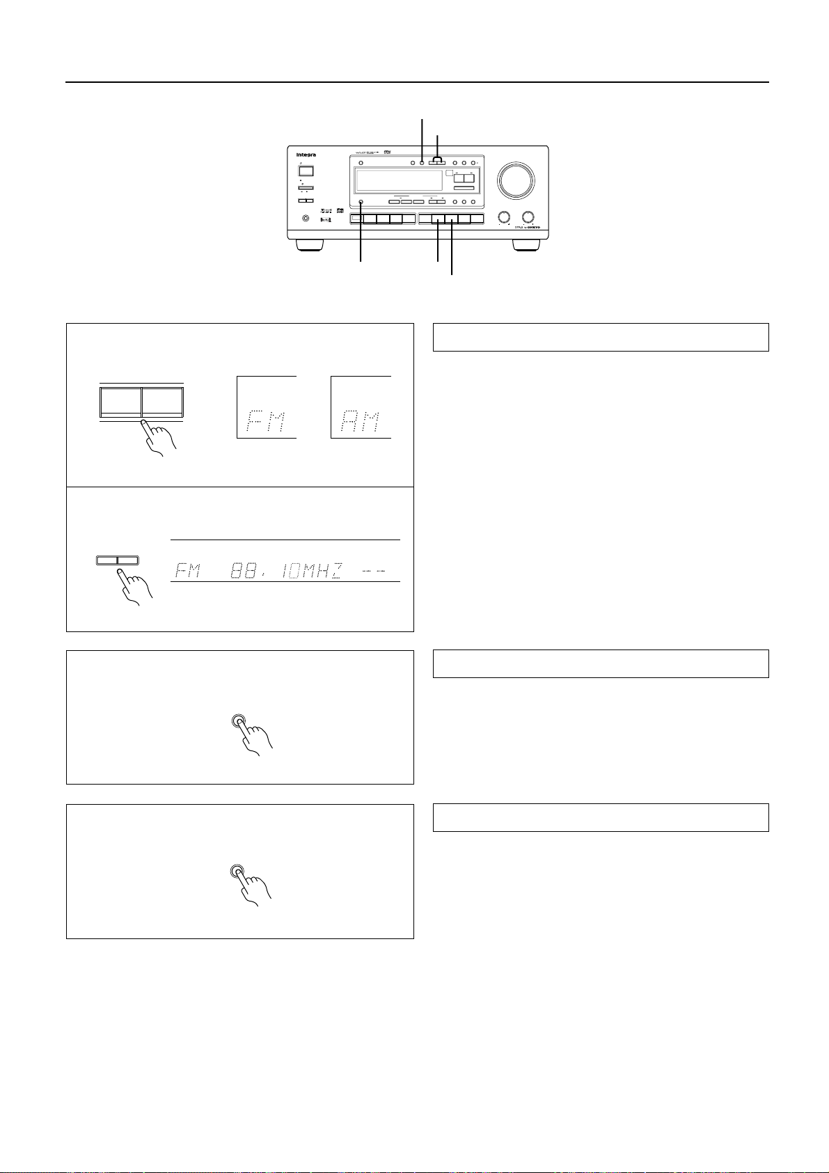
Tuning in a radio station
FM MUTE/MODE
TUNING DOWN/UP
STANDBY/ON
STANDBY
POWER
ON
OFF
SPEAKERSAB
PHONES
DIMMER
DISPLAY
MULTI
CH
INPUT
DISPLAY
DIGITAL/
MUTE /
FM
MEMORY
LISTENING MODE
SURROUND
/DTS
STEREO
CH STEREO
5
VIDEO 3
VIDEO 2
VIDEO 1
SP / SYS
ANALOG
MODE
SETUP
TUNING
UPDOWN
PRESET / MODE ADJ
DOW NUP
ENTER / SCAN
NIGHT /
LATE
EFFECT
FRONT
DSP
Re -EQ
AM PHONO C
FM
TAPEDVD
FM
MASTER VOLUME
CH LEVEL
MODE
LFE LEVEL
CONTROL
D
TREBLE
BASS
AM
1
Manual tuning
1. Press the FM or AM button.
AM
FM
2. Use the TUNING UP/DOWN buttons to change the frequency.
UP.....................the frequency increases.
DOWN..............the frequency decreases.
• The frequency changes in 50 kHz steps in FM and 10 kHz in
AM each time you press the TUNING UP/DOWN button.
• In FM, if this button is held continuously for more than 0.5 sec-
onds, the frequencies are scanned automatically (FM auto tun-
2
TUNING
UPDOWN
ch
ing mode). When a broadcast is received, scanning stops.
FM MUTE /
MODE
DISPLAY
Listening to a stereo radio station (FM mode)
When you tune in a stereo FM station, the FM STEREO indicator
lights up if the signal is sufficiently strong.
If the signal is weak, it may be impossible to tune in to the desired
station. In this case, tune in as follows.
Press the FM MUTE/MODE button. The FM MUTE indicator
turns off. At this time, the station will be in mono and interstation
noise will be heard. Select the station to which you want to listen.
DISPLAY button
Pressing the DISPLAY button each time will change the indication
as follows:
Frequency (preset No.)
↔ Listening mode
24
Page 25
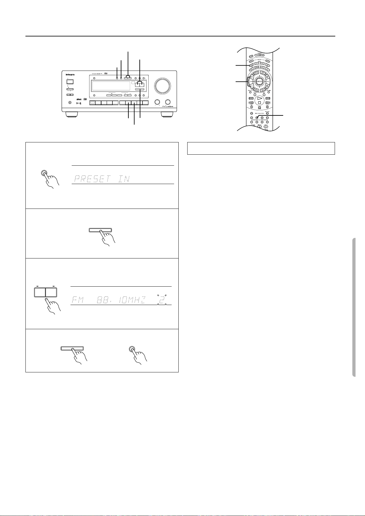
Using preset radio stations
TUNING DOWN/UP
FM MUTE/MODE
MEMORY
STANDBY/ON
STANDBY
POWER
ON
OFF
SPEAKERSAB
PHONES
DIMMER
DISPLAY
CH
MULTI
INPUT
MEMORY
LISTENING MODE
SURROUND
STEREO
/DTS
VIDEO 3
VIDEO 2
VIDEO 1
PRESET/MODE ADJ
DIGITAL/
FM
MUTE /
SP / SYS
ANALOG
MODE
5
CH STEREO
TAPEDVD
TUNING
DSP
FM
UPDOWN
FRONT
SETUP
PRESET / MODE ADJ
DOW NUP
ENTER / SCAN
NIGHT /
LATE
EFFECT
Re -EQ
AM PHONO C
CH LEVEL
MODE
LFE LEVEL
CONTROL
D
MODE AUDIO
MASTER VOLUME
TREBLE
BASS
CH +/–
2
MEMORY
3
4
PRESET / MODE ADJ
DOW NUP
ENTER / SCAN
FM
ENTER/SCAN
AM
TUN
Programming radio stations
1. Select the frequency that you want to store in the memory.
(See Tuning in a radio station on page 24.)
2. Press the MEMORY button.
“PRESET IN” appears.
3. Press the ENTER/SCAN button while the PRESET IN indicator is illuminated.
The “MEMORY” indicator lights up on the display.
4. Select the desired memory number using PRESET/MODE
ADJ √/®button.
5. Press the ENTER/SCAN or MEMORY button.
The received station will be stored in the specified preset number.
• A total of 30 stations can be stored in the memory.
ch
5
ENTER / SCAN
or
MEMORY
25
Page 26
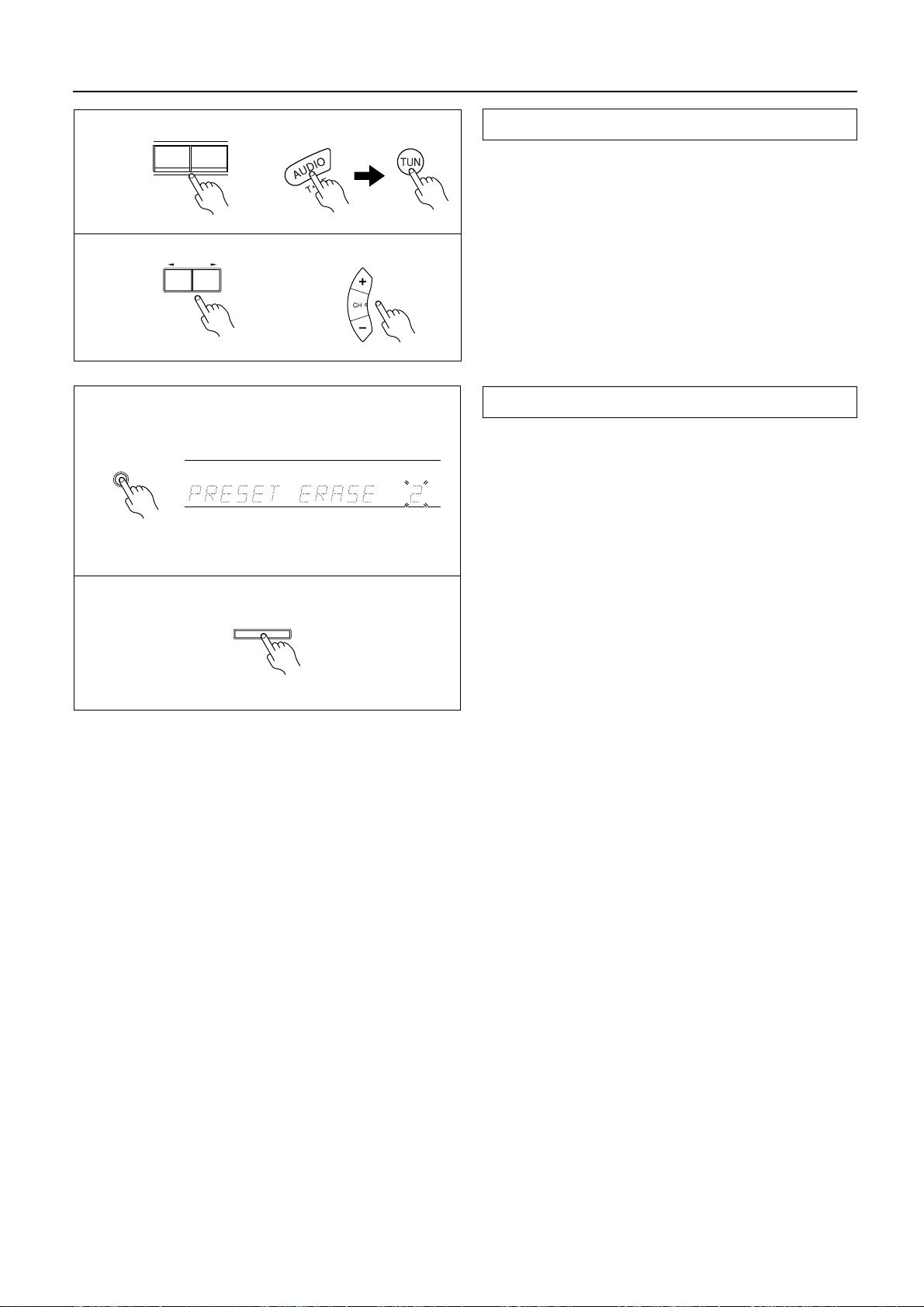
Using preset radio stations
Selecting a preset station
1. Select the tuner as the source by pressing the AM or FM
input selector button on the main unit.
2. Enter the desired preset number using the PRESET/MODE
ADJ √/® button.
Remote controller operation
1. Press the MODE AUDIO button.
2. Select the tuner as the source by pressing the TUN input
selector button on the remote controller.
3. Press the CH (– or +) button.
Cancelling preset stations
1. Select the preset station you wish to remove as explained in
the previous section.
2. Press the MEMORY button twice.
“PRESET ERASE” appears on the display.
3. While “PRESET ERASE” is displayed, press the ENTER/
SCAN button.
3
Remote controller
Remote controller
1
2
FM
PRESET / MODE ADJ
DOW NUP
AM
1, 2
2
MEMORY
ch
• Once the preset station has been cancelled, the memory location
can be used to store another station.
3
ENTER / SCAN
26
Page 27
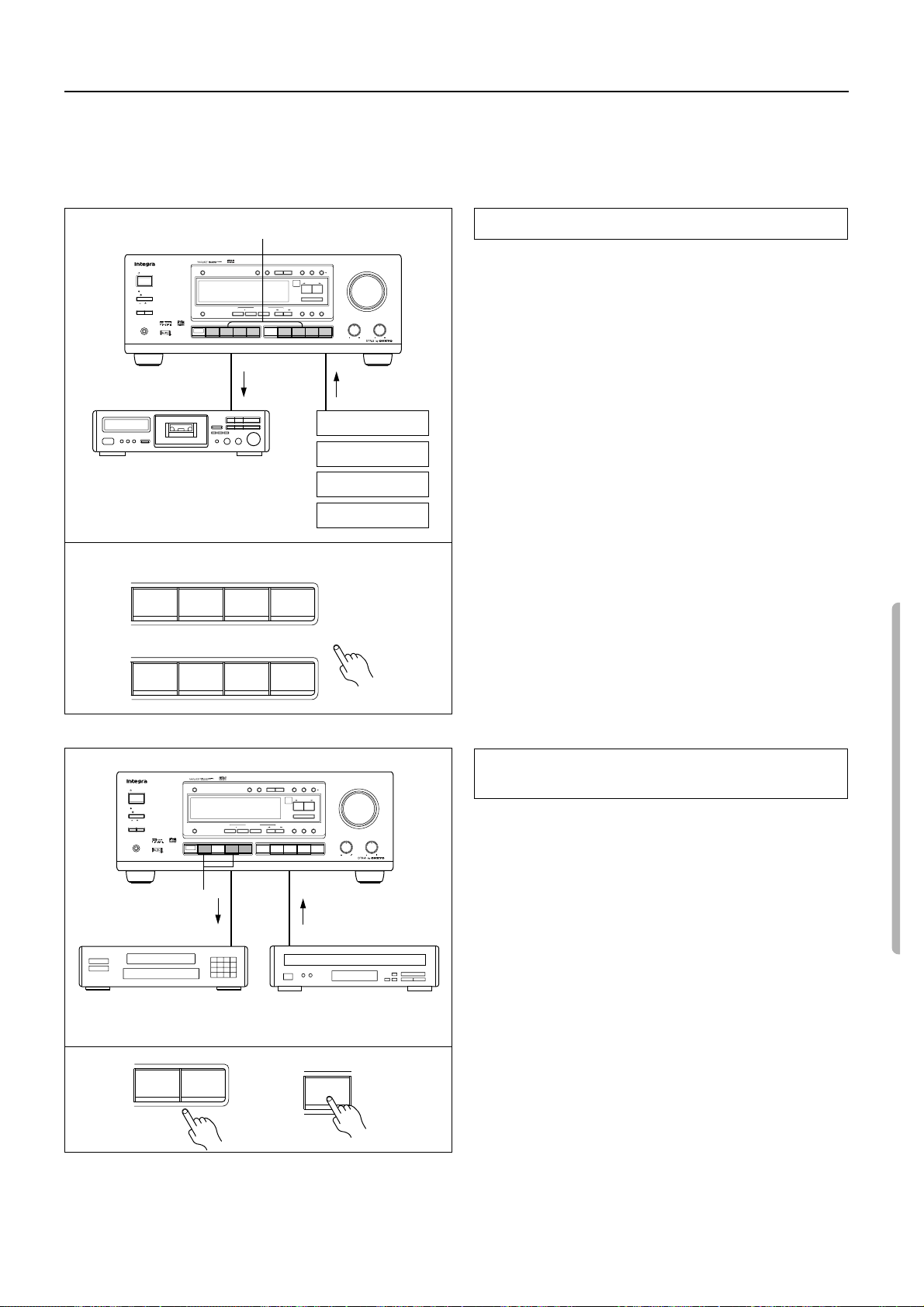
Recording a source
•
You can record analog Audio, but not digital audio. Make sure that you have made a correct analog connection.
•
You cannot record the source connected to MULTI CHANNEL INPUT jack.
•
If you select another device as the input source during recording, the input signal from that device will be recorded.
You cannot record audio source along with the surround effects.
•
1
STANDBY/ON
STANDBY
POWER
ON
OFF
SPEAKERSAB
PHONES
DIMMER
DISPLAY
CH
MULTI
INPUT
2
DIGITAL/
FM
MUTE /
SP / SYS
ANALOG
MODE
SETUP
TUNING
UPDOWN
MEMORY
LISTENING MODE
/DTS
SURROUND
STEREO
VIDEO 3
VIDEO 2
VIDEO 1
PRESET / MODE ADJ
DOW NUP
ENTER / SCAN
NIGHT /
LATE
CH STEREO
5
EFFECT
FRONT
DSP
Re -EQ
AM PHONO C
TAPEDVD
FM
MASTER VOLUME
CH LEVEL
MODE
LFE LEVEL
CONTROL
D
TREBLE
BASS
1·3 3
Turntable
CD player
Tape deck
(TAPE)
VCR, VDP
DVD
2
VIDEO 3
DVD
FM
VIDEO 2
VIDEO 1
AM PHONO C
D
Recording an audio source
Make all connections between the tape deck and the receiver as
shown in the “Audio equipment connections” diagram (page 6).
1. Insert a blank tape into the tape deck.
2. Press the input selector button for the source you want to
record.
•
If you select DVD, VIDEO 1, VIDEO 2 or VIDEO 3, only the
audio will be recorded.
•
If you select FM or AM, set the tuner to the station you want to
record.
3. Set the tape deck in recording mode. Start playing the
source.
Set the proper recording level using the controls on the tape
deck.
•
Please read the corresponding instruction manuals for more
information on how to operate the corresponding equipment.
1
STANDBY/ON
STANDBY
POWER
ON
OFF
SPEAKERSAB
PHONES
DIMMER
SURROUND
STEREO
/DTS
DISPLAY
VIDEO 3
VIDEO 2
VIDEO 1
CH
MULTI
INPUT
MEMORY
LISTENING MODE
DIGITAL/
MUTE /
FM
SP / SYS
ANALOG
MODE
SETUP
TUNING
UPDOWN
PRESET / MODE ADJ
DOW NUP
ENTER / SCAN
NIGHT /
LATE
5
CH STEREO
EFFECT
FRONT
DSP
Re -EQ
AM PHONO C
FM
TAPEDVD
MASTER VOLUME
CH LEVEL
MODE
LFE LEVEL
CONTROL
D
TREBLE
BASS
2
1·3 1·3
2
VCR
(VIDEO 1)
VIDEO 2
VIDEO 3
VDP, DVD player
(VIDEO 2, VIDEO 3)
DVD
or
Recording data from a video disc player (or a
video camcorder) to VCR
Video disc programs can be recorded onto a VCR (VIDEO 1).
1. Load a disc in the video disc player or DVD player, and
insert a blank tape in the VCR (VIDEO 1).
2. Press the VIDEO 2, VIDEO 3 or DVD button.
3. Start playing the video disc player and recording on the
VCR.
•
Refer to the Video equipment connections section on the page 7.
27
Page 28
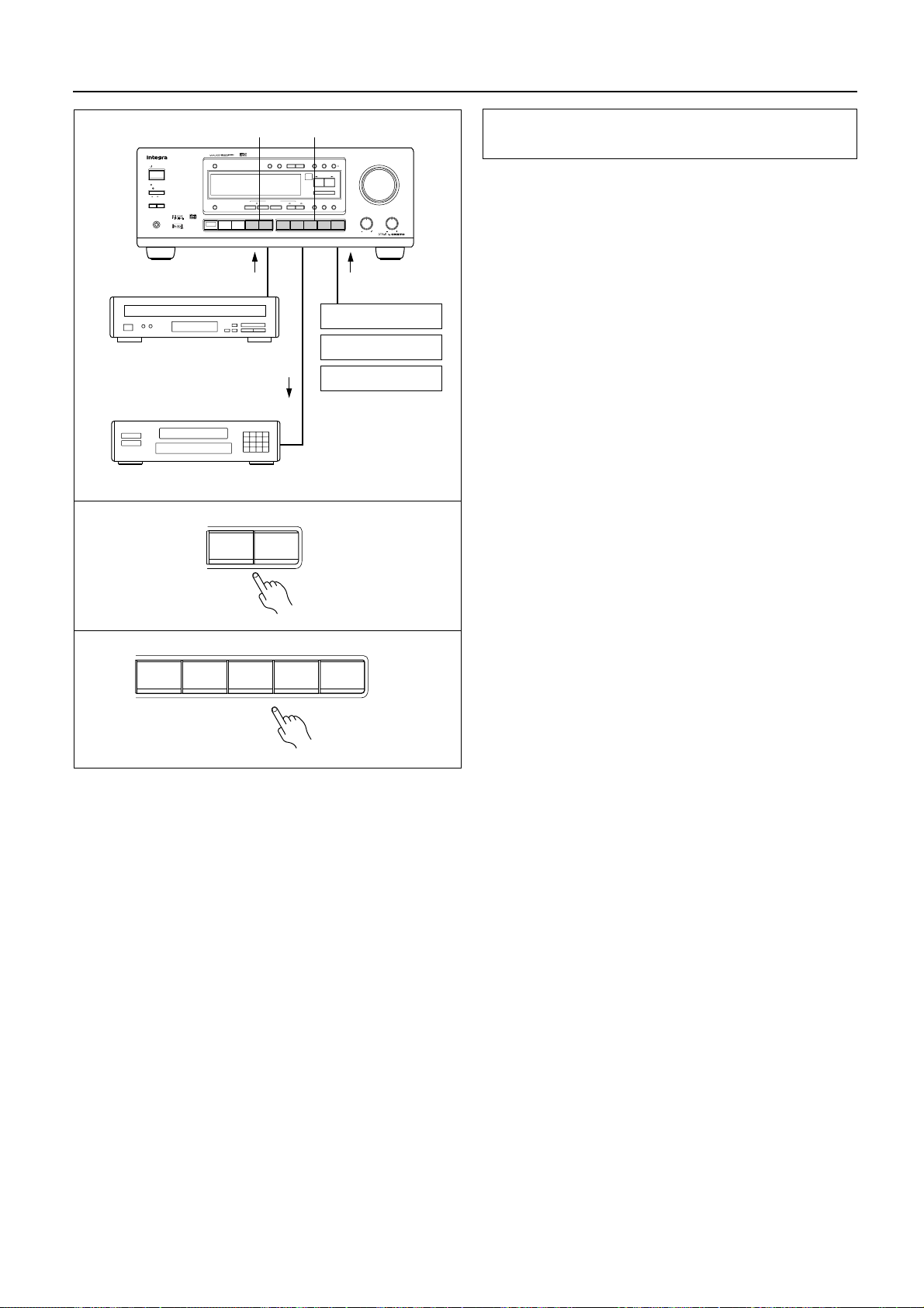
Recording a source
1
STANDBY/ON
STANDBY
POWER
ON
OFF
SPEAKERSAB
PHONES
1·5
VDP, VCR, DVD
(VIDEO 2, VIDEO 3)
2·5
VCR (VIDEO 1)
3
Adding new sound to a video tape during video
editing
During video tape editing, you can add sound to the recording
VCR from various audio program sources.
1. Insert the disc or tape that you want to record into the
player connected to VIDEO 2 or VIDOE 3.
MEMORY
LISTENING MODE
4
DIGITAL/
FM
MUTE /
SP / SYS
ANALOG
MODE
SETUP
TUNING
UPDOWN
PRESET / MODE ADJ
DOW NUP
ENTER / SCAN
NIGHT /
LATE
5
CH STEREO
EFFECT
FRONT
DSP
Re -EQ
AM PHONO C
TAPEDVD
FM
MASTER VOLUME
CH LEVEL
MODE
LFE LEVEL
CONTROL
D
TREBLE
BASS
3
DIMMER
SURROUND
STEREO
/DTS
DISPLAY
VIDEO 3
VIDEO 2
VIDEO 1
CH
MULTI
INPUT
2. Insert a blank video tape in the VCR connected to VIDEO 1.
3. Press the VIDEO 2 or 3 button.
5
Turntable
4. Select the audio program source (TAPE, FM, AM, PHONO,
CD).
5. Start playing the video connected to the VIDEO 2 or
CD player
VIDEO 3 terminal and start playing the sound source. Then,
start recording on the VCR that is connected to the
TAPE
VIDEO 1 terminal.
Refer to the video disc player, video camcorder, DVD or VCR
•
instruction manuals for additional information.
VIDEO 3
VIDEO 2
4
TAPE
FM
AM PHONO C
D
28
Page 29
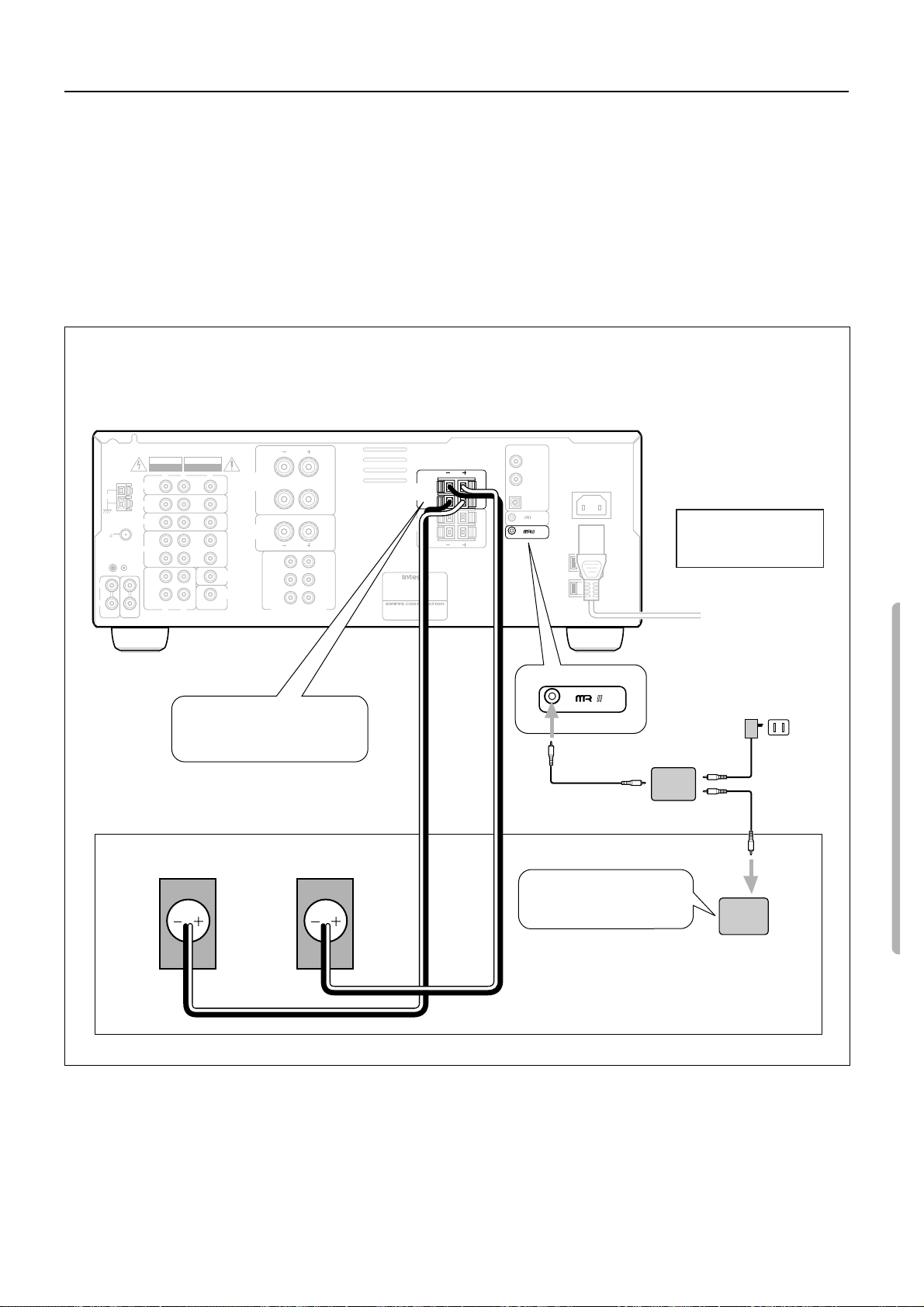
Enjoying Music and Movies in the Sub-room
Outline of Multi-room Remote System
If you connect Onkyo Multi-room Remote System components as shown in the figure below, you can control the components from an adjacent sub-room as well as from the room where the DTR-5 is located.
The following equipment (sold separately) is essential for using the Onkyo Multi-Room System:
•
Onkyo’s Multi-Room System kits HKT-600 or HKT-700 (IR Remote Controller Extension System), or
•
Multiroom A/V distribution and control systems from Niles
®
and Xantech
®
to name a few
Connections in the Sub-room
Make connection as shown below. Do not plug the equipment into the power source until the connection is complete.
DTR-5
DIGITAL INPUT
COAXIAL 2
COAXIAL 1
OPTICAL
REMOTE CONTROL
AC I NLET
AC 120V 60Hz
SWITCHED
TOTAL 120W 1A MAX.
Connection example of
System Kit HKT-600
HB-100
Connecting block
ANTENNA
L
R
PHONO
AVIS
WARNING
RISK OF ELECTRIC SHOCK
RISQUE DE CHOC ELECTRIQUE
DO NOT OPEN
NE PAS OUVRIR
V
L
R
N
DVD
AM
VIDEO 3
VIDEO 2
FM
75
VIDEO 1
GND
(
TAPE
(
C D
I
I N
N
I
I
N
OUT
)
PLAY
I
N
V
OUT
)
REC
L
R
1
Connect speaker cables for
MONITOR
OUT
SUBWOOFER
PRE OUT
FRONT
SPEAKERS
A
CENTER
SPEAKER
L
R
FRONT
SURROUND
CENTER
MULT I CHANNEL I NPUT
L
L
FRONT
SPEAKERS
R
CAUTION: SPEAKER IMPEDANCE
6 OHMS MIN. PER EACH
SPEAKER TERMINAL
R
L
L
R
SUB
WOOFER
B
SURROUND
SPEAKERS
AV RECEIVER
MODEL NO. DTR-5
RATING:
AC120V 60Hz 3.9A
2-1, NISSHIN-CHO, NEYAGAWA-SHI,OSAKA,
JAPAN
MANUFACTURED IN MALA
L
R
R
L
L
R
R
YSIA
the sub-room to the FRONT
SPEAKERS B jacks.
Onkyo Multi-room
Power supply
120 V AC
(Unswitched)
Right speaker
when seen from the front
Left speaker
when seen from the front
2
Locate a Remote Sensor
in the sub-room.
Remote sensor
HR-600
SUB ROOM
29
Page 30
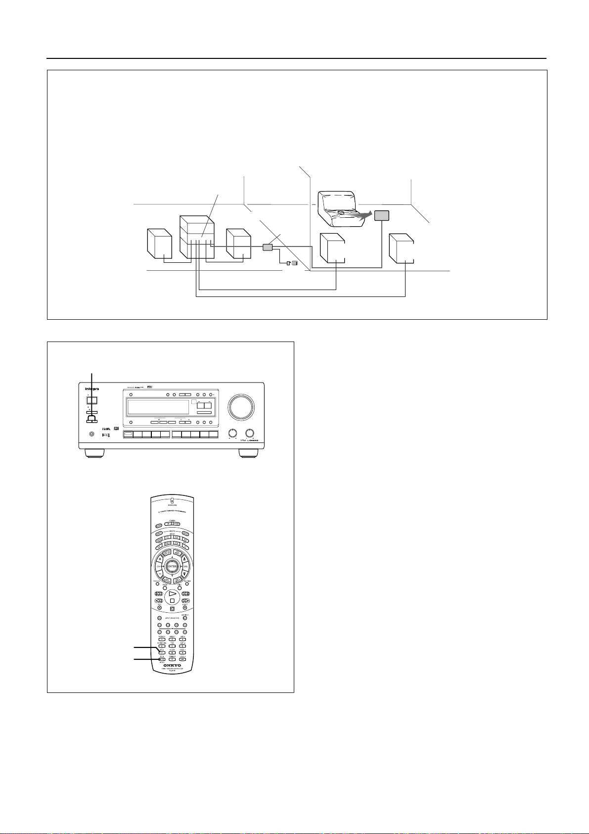
Enjoying Music and Movies in the Sub-room
Outline of Multi-room Remote System
If you connect Onkyo Multi-room Remote System components as shown below, you can control the components from an adjacent subroom as well as from the room where the DTR-5 is located.
MAIN ROOM SUB ROOM
Speaker A
(Main room)
SPEAKERS A/B
STANDBY/ON
STANDBY
POWER
ON
OFF
SPEAKERSAB
PHONES
DIMMER
DISPLAY
MULTI
CH
INPUT
DTR-5
Remote
Speaker A
(Main room)
Connecting
block
Power
supply
controller
Speaker B
(Sub room)
Remote
sensor
Speaker B
(Sub room)
You can operate the main unit with the remote controller from the
main room and Sub-room.
Use the remote controller to control the system in the sub-room.
Pointing the remote controller toward the remote sensor.
DIGITAL/
FM
MUTE /
SP / SYS
ANALOG
MODE
MEMORY
LISTENING MODE
/DTS
SURROUND
STEREO
CH STEREO
5
VIDEO 3
VIDEO 2
VIDEO 1
SETUP
TUNING
UPDOWN
PRESET / MODE ADJ
DOW NUP
ENTER / SCAN
NIGHT /
LATE
EFFECT
FRONT
DSP
Re -EQ
AM PHONO C
FM
TAPEDVD
MASTER VOLUME
CH LEVEL
MODE
LFE LEVEL
CONTROL
D
TREBLE
BASS
Note:
If you are listening to music both in the main room and sub-
•
room, turn SPEAKERS A and B on. However, if you select
MULTI CH INPUT or use Surround mode in the main room,
the audio in the sub-room will be muted.
If you are listening to music only in the sub-room, press the
•
SPEAKERS A button to turn off the speaker output in the main
room.
When you finish listening to music in the sub-room, turn down
the speaker volume to the minimum so that a sudden loud volume will not surprise you next time you use the system.
Please note that some third-party multi-room system compo-
•
nents may not be fully compatible with the Onkyo multi-room
system components.
30
SP A
SP B
Page 31
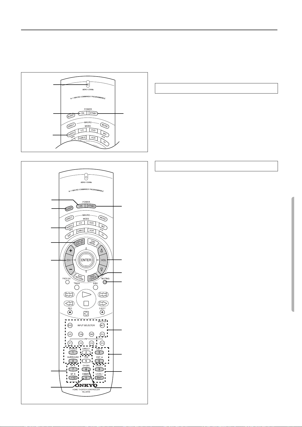
/
/
Using the remote controller
Overview
When you use a remote controller, typically you press one of the MODE buttons that corresponds to the device you wish to control, then
press the operation buttons. For example, if you wish to control the DTR-5 from a remote controller, first press the MODE AUDIO button,
then press an appropriate operation button. To control a CD player, press the MODE CD button, then press an appropriate operation button.
First, press the desired MODE button to make sure that the DTR-5 is set to a correct mode.
Using the RC-391M to control each device
SEND/LEARN
indicator
POWER ON
MODE AUDIO
POWER ON
SLEEP
MODE
AUDIO
DISPLA Y
CH +/–
POWER
STNBY
POWER
STNBY
VOL
TEST
MUTING
Turning the power on and off to the DTR-5
Note:
Before operating the RC-391M, turn on the POWER switch on the
DTR-5 so that the unit enters standby mode.
1. Press the MODE AUDIO button.
2. Pressing the POWER ON buttons will switch power on.
Pressing the POWER STNBY button will power standby.
SEND/LEARN indicator
This indicator acts as a guide when commands are programmed
into or sent by the remote controller. It also warns the user when
an error is made or battery power is low.
Controlling the DTR-5
1. Press the MODE AUDIO button.
2. Press the desired operation button.
Shaded buttons in the figure are the operation buttons used to
control the DTR-5.
SLEEP
POWER ON/STNBY
DISPLAY : Changing the display
VOL
q
CH +/–
INPUT SELECTOR
Listening mode ( STEREO / DSP
SP A/SP B : Switching between Speakers A and B
CH SEL
DIMMER : Adjusting the brightness of the display
LEVEL +/– : Adjusting the speaker levels
TEST
MUTING
: Sleep function
: Power on/standby
/
u
: Adjusting the volume
: Tuner preset number increment/decrement
√
DSP
®
: Changing Listening mode
: Selecting a speaker
: Test tone
: Muting
SURROUND )
SP A/B
DIMMER
INPUT
SELECTOR
Litening
mode
LEVEL +/–
CH SEL
31
Page 32
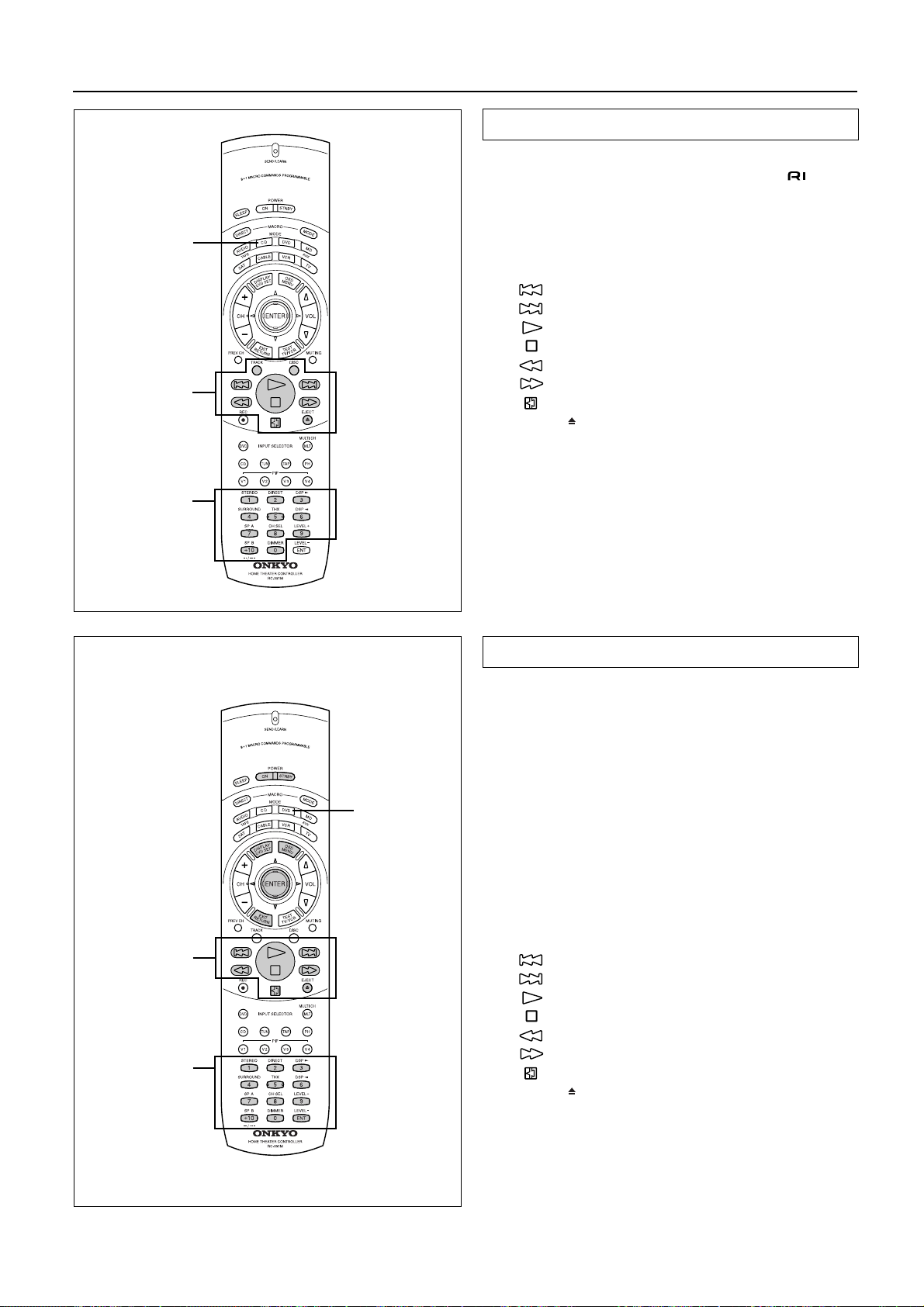
Using the remote controller
MODE CD
CD
operation
buttons
Controlling an Onkyo/Integra CD player
Note:
First connect an Onkyo/Integra CD player using the connection.
1. Press the MODE CD button.
2. Press the desired CD operation button.
TRACK
DISC
EJECT : Eject
0, 1~9, +10 : Numeric keys
: Selecting a track
: Selecting a disk in the CD changer
:Down
:Up
: Playback
: Stop
: Rewind
: Fast forward
: Pause
Numeric keys
DVD
operation
buttons
Numeric keys,
ENT button
MODE DVD
You may also use the following buttons:
VOL
q
/
u
: Adjusting the volume level of the DTR-5
MUTING
: Muting the sound from the DTR-5
Controlling an Onkyo/Integra DVD player
Note:
Make sure that you point the transmission part on the remote controller toward the sensor area on the DVD player.
1. Press the MODE DVD button.
2. Press the desired DVD operation button.
POWER ON/STNBY
: Turning the power on and off to the DVD
player
DVD SET : DVD setup
DVD player on-screen button
MENU
ququ
ENTER
RETURN : Return
DVD player buttons
EJECT : Eject
0, 1~9, +10 : Numeric keys
ENT
: Displaying the menu
: Moving the cursor
: Confirming the selection
:Down
:Up
: Playback
: Stop
: Rewind
: Fast forward
: Pause
: Confirm
32
You may also use the following buttons:
VOL
q
/
u
: Adjusting the volume level of the DTR-5
MUTING
Note:
The ENT button on the right below the numeric keys has the same
function as “ENTER” of the ENTER/cursor button.
: Muting the sound from the DTR-5
Page 33
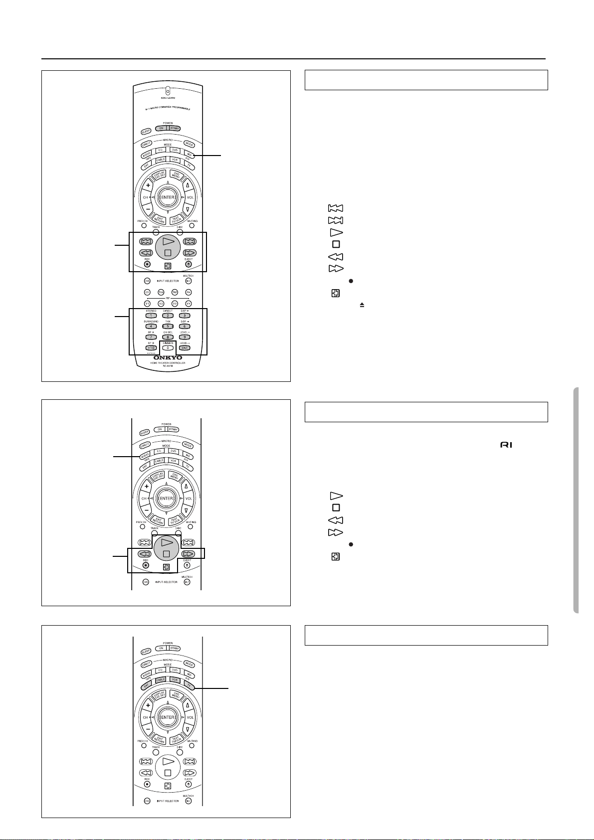
Using the remote controller
MD
operation
buttons
Numeric keys,
ENT button
MODE MD/AUX
Controlling an Onkyo/Integra MD recorder
Note:
Make sure that you point the transmission part on the remote controller toward the sensor area on the MD recorder.
1. Press the MODE MD/AUX button.
2. Press the desired MD operation button.
Turning the power on and off to the MD recorder
POWER ON/STNBY
: Turning on or standby the power to the MD
recorder
:Down
:Up
: Playback
: Stop
: Rewind
: Fast forward
REC
EJECT : Eject
1~9, +10
ENT
: Record
: Pause
: Numeric keys
: Confirm
MODE
AUDIO/TAPE
TAPE
operation
buttons
You may also use the following buttons:
VOL
q
/
u
: Adjusting the volume level of the DTR-5
MUTING
: Muting the sound from the DTR-5
Controlling an Onkyo/Integra tape deck
Note:
First connect an Onkyo/Integra tape deck using the connection. (See page 9.)
1. Press the MODE AUDIO/TAPE button.
2. Press the desired tape deck operation button.
: Playback
: Stop
: Rewind
: Fast forward
REC
You may also use the following buttons:
VOL q/u : Adjusting the volume level of the DTR-5
MUTING : Muting the sound from the DTR-5
: Recording/pause
: Reverse playback
MODE SAT, CABLE, VCR, and TV buttons
MODE SAT,
CABLE, VCR,
TV
No preset codes are programmed into the MODE SAT, CABLE,
VCR, and TV buttons. You can use these buttons to program
remote controller signals of other devices. (See page 34.)
You may use the following buttons:
VOL q/u : Adjusting the volume level of the DTR-5
MUTING : Muting the sound from the DTR-5
33
Page 34
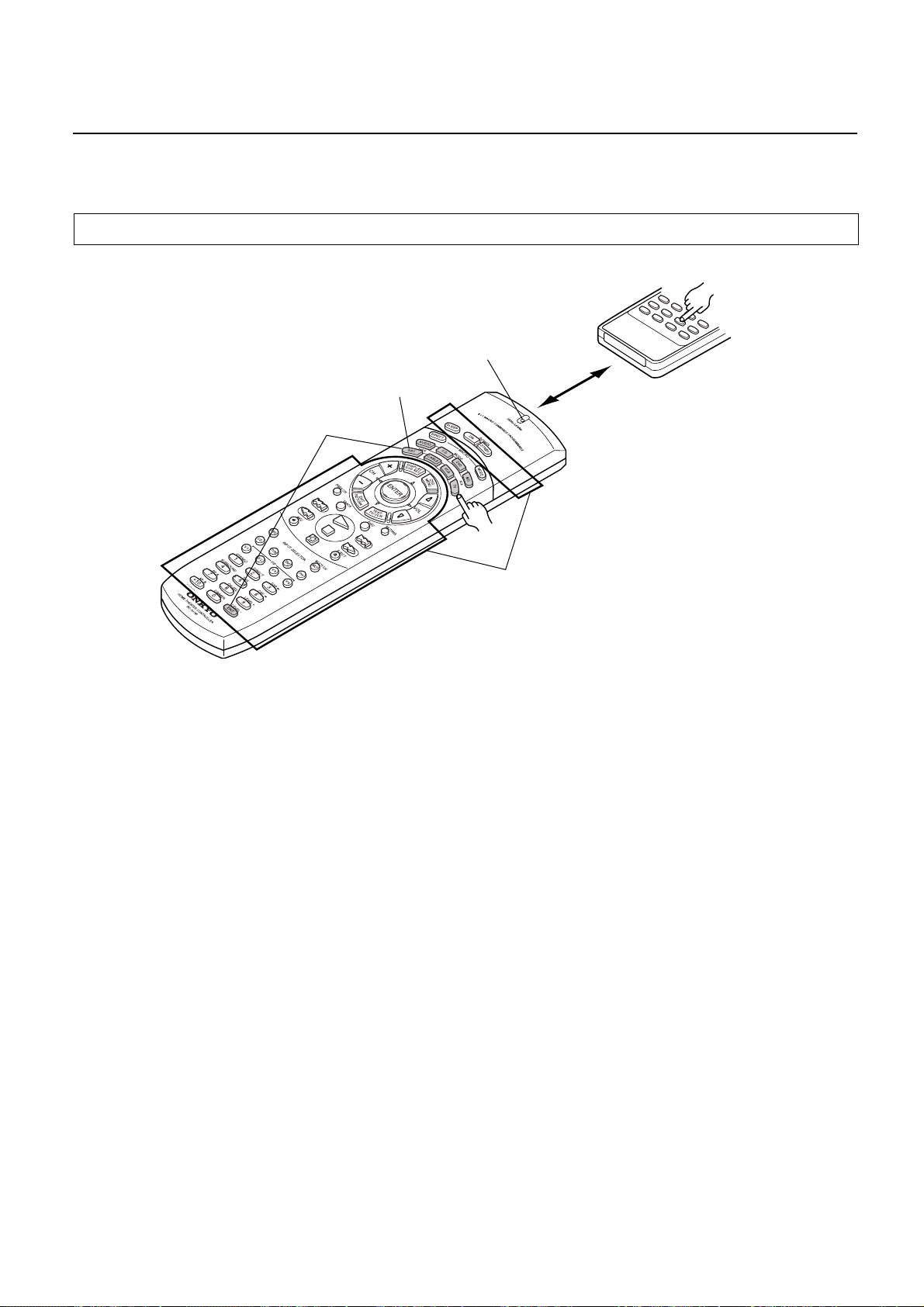
Programming the remote contr oller codes of
other devices into the RC-391M
The RC-391M has two learning functions. One is a normal learning function that enables the RC-391M to learn other remote controllers’
codes. The other is a macro learning function, which enables the RC-391M to learn a series of codes already memorized in the remote controller into one MACRO button.
Programming procedure
Program the codes for each mode (AUDIO, CD, DVD, MD, SAT, CABLE, VCR, and TV).
Light
6
1
5 to 15 cm
2
(2 to 6 inches)
4
RC-391M
1. Place the RC-391M and the remote controller for another
device, with 5–15cm (2–6 inches) apart and the light-emitting parts facing each other.
2. While pressing and holding down the desired MODE button
on the RC-391M (AUDIO, CD, DVD, MD, SAT, CABLE,
VCR, or TV), press the ENT button, then release the buttons.
When you press and hold down one of the MODE button, the
SEND/LEARN indicator lights up. When you press the ENT
button, the indicator turns off. When you release the b uttons, the
SEND/LEARN indicator lights up again.
3. Press and release the desired operation button on the RC391M.
You may select any button within the rectangle shown in the figure.
When you press the button, the SEND/LEARN indicator turns off.
When you release the button, the indicator lights up again.
4. Press and hold down the desired button on the remote controller of the other device until the SEND/LEARN indicator
on the RC-391M flashes twice.
The SEND/LEARN indicator flashes twice slowly , then lights up.
5. Repeat Steps 3–4 to program other buttons in the same
MODE.
Repeat Steps 2-4 to program other buttons in a different MODE.
6. Press the MODE button to complete programming.
7. Operate the programmed button to make sure the learning
function works.
Note:
The remote controller codes for the Onkyo/Integra CD player,
tape deck, DVD player, and MD recorder have already been
programmed into the buttons on the RC-391M. You may program other remote controller codes into these buttons. If you
wish to restore the Onkyo/Integra preset codes after you program new codes, erase the new codes. (See page 35.)
34
3
The button you wish to memorize
Note:
• The remote controller has 408 memory slots (51 buttons × 8
modes), although this number varies significantly depending on
the manufacturers and types of the remote controller you wish to
program into the RC-391M. It is recommended that you determine which button functions have priority for programming.
• If you do not press any button for more than 30 seconds during
the procedure, the SEND/LEARN indicator flashes three times
quickly, then the RC-391M e xits Learning mode. Resume Step 2.
• If you make a mistak e during programming, the SEND/LEARN
indicator flashes three times quickly, then the RC-391M exits
Learning mode.
• If you try to program beyond the learning capacity of the RC-
391M, the SEND/LEARN indicator flashes six times quickly,
then the RC-391M exits Learning function. Try programming in
a button of other MODE.
• Follow the same procedure when you wish to program new
codes into the already-programmed buttons.
• This remote controller uses infrared rays. Most remote control-
ler codes can be memorized using the infrared system; however,
depending on the degree to which the system differs, there may
be some rare occasions when memorization is not possible.
• Some remote controllers use a single b utton to perform dif ferent
functions, with the function code changing each time the button
is pressed. If you are using this kind of controller, please perform the “learn” operations for each function individually to
store each function to a button on the RC-391M.
• For instructions regarding the operation of “learned” units,
please refer to the instruction manual for each product.
• Even after codes have been memorized, please keep your old
remote controller in a safe place. If the memorized codes are
lost when the batteries run down, it will be necessary to memorize them once again using the old remote controller.
• Make sure both the RC-391M and the product’s own remote
controller have fresh batteries. If either of them has batteries
that are wearing down, it may be impossible to store the remote
controller codes into the RC-391M or the product may not
respond properly to the buttons on the RC-391M for which the
remote controller codes were stored into memory.
Page 35
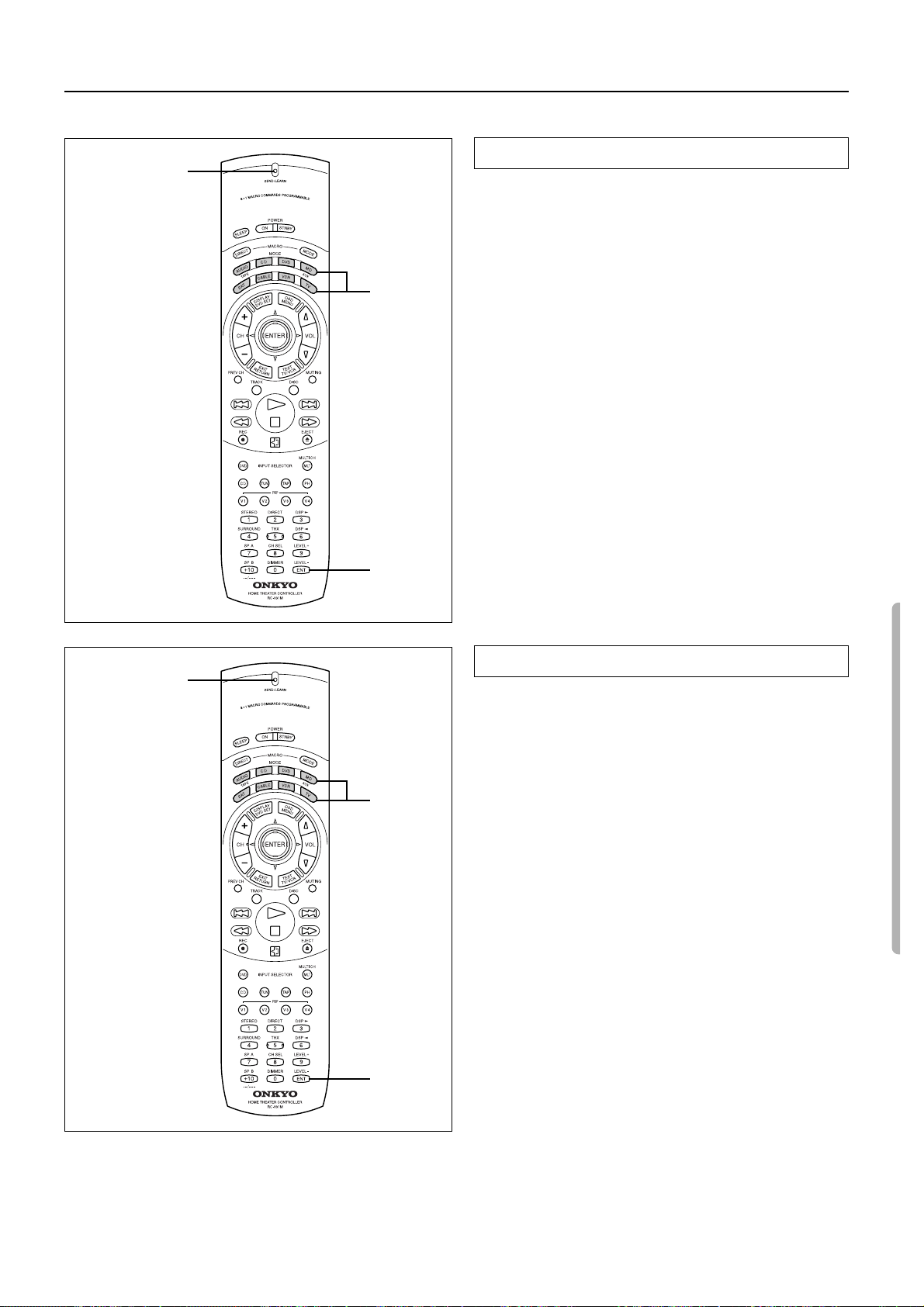
Programming the remote controller codes of other de vices into the RC-391M
See page 39 for information on how to erase the learned codes from all buttons.
Erasing a learned code
SEND/LEARN
indicator
MODE
buttons
You can erase a learned code. You cannot erase preset codes.
• Erasing a code programmed in a button
1. Press and hold down the corresponding MODE button and
press the ENT button, then release the buttons.
When you press the MODE button, the SEND/LEARN indicator lights up. When you press the ENT button, the indicator
turns off. When you release the buttons, the indicator lights up
again.
2. Press and release the button from which you wish to erase
the learned code.
When you press the button, the SEND/LEARN indicator turns
off. When you release the button, the indicator lights up again.
3. Press and release the same button again.
The SEND/LEARN indicator flashes twice slowly. The learned
code is erased.
Note:
• If you do not press the button in step 2 or 3 for more than 30 sec-
onds, the SEND/LEARN indicator flashes three times quickly,
then the RC-391M exits Learning mode. Resume Step 1.
SEND/LEARN
indicator
ENT
MODE
buttons
Erasing a learned code from a MODE button
1. Press and hold down the MODE button from which you
wish to erase the learned code, and press the ENT button
twice. Then release the buttons.
When you press the MODE button, the SEND/LEARN indicator lights up. When you press the ENT button, the indicator
turns off. When you release the buttons, the indicator flashes
twice slowly, then lights up again.
2. Press and release the same MODE button again.
When you release the button, the SEND/LEARN indicator
flashes twice slowly. The learned code is erased.
Note:
• If you do not press any button for more than 30 seconds, the
SEND/LEARN indicator flashes three times quickly, then the
RC-391M exits Learning mode. Resume Step 1.
• If you make a mistak e during programming, the SEND/LEARN
indicator flashes three times quickly, the RC-391M exits Learning mode. Resume Step 1.
• If have programmed many button operations to a single MODE
button, the SEND/LEARN indicator may remain illuminated
continuously in Step 2. This is not malfunction.
ENT
35
Page 36
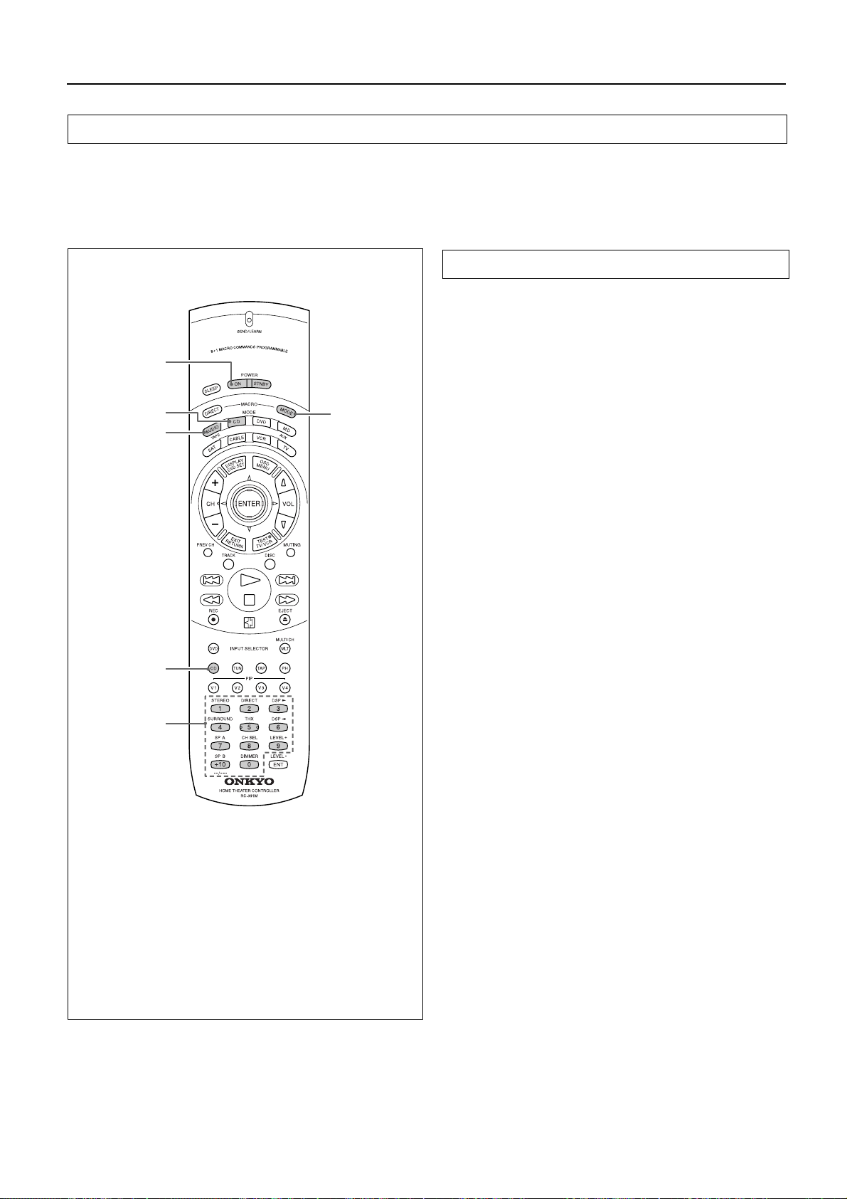
Using a Macro function
What is a Macro function?
A Macro function enables you to program a series of button operations on the remote controller into a single button. For example, you need
to follow the steps below to play a CD player connected to the DTR-5 without using the Macro function:
1: Press the MODE AUDIO button. → 2: Press the POWER ON button. → 3: Press the CD (INPUT SELECTOR) button. → 4: Press the
MODE CD button. → 5: Use the numeric keys to select the desired song.
This operation will be two button presses away if you program these steps into a macro button.
Programming Macro mode
You may program the desired steps into each of eight MODE buttons. The following example explains how to program Steps 1–5
(described above) into the MACRO MODE button under the
MODE CD button (CD mode).
1. Press and hold down the desired MODE button you wish to
program (in this case, MODE CD button), and press the
MACRO MODE button. Then release the buttons.
When you press the MODE CD button, the SEND/LEARN
indicator lights up. When you press the MACRO MODE button,
the indicator turns off.
When you release the buttons, the indicator flashes briefly, then
lights up again.
2. Press the operation buttons in series you wish to program
into the MACRO MODE button.
Press the MODE AUDIO, POWER ON, CD (INPUT SELECTOR), MODE CD buttons, and a numeric key. When you press
the button, the SEND/LEARN indicator turns off. When you
release the button, the indicator lights up.
3. Press the MACRO MODE button to complete programming.
The SEND/LEARN indicator flashes twice slowly.
Repeat Steps 1–3 to program other series of button operations
into another MODE button.
4. Check to see if the series of button operation has been correctly learned.
Point the remote controller toward the DTR-5, press the MODE
CD button, and press the MACRO MODE button to see if the
unit responds as programmed.
Transmitting the codes in Macro mode takes a while. During
transmission, point the remote controller toward the device to
be controlled.
1, 2
2
1, 3
2
2
2
36
Tip:
The codes programmed into a MACRO button will be
transmitted with an interval of 0.5 seconds. However,
some devices may not be able to complete one operation in 0.5 seconds and may miss the next code. In this
case, press one operation button, press the corresponding MODE button, then press another operation button
to extend the interval between the two operations up to
one second.
Note:
• You may program up to 16 button operations into each MACR O
button. If you try to program the 17th step, it will be ignored.
• If you do not press any button for more than 30 seconds during
the procedure, the SEND/LEARN indicator flashes three times
quickly, then the RC-391M exits Learning mode. Resume Step
1.
• If you make a mistak e during programming, the SEND/LEARN
indicator flashes three times quickly, then the RC-391M exits
Learning mode. Resume Step 1.
• If you erase one of the operation b uttons already programmed in
the MACRO MODE button, or if you program a different code
into such a button, the operation button will no longer work. In
this case, program the buttons again to avoid malfunction.
Page 37
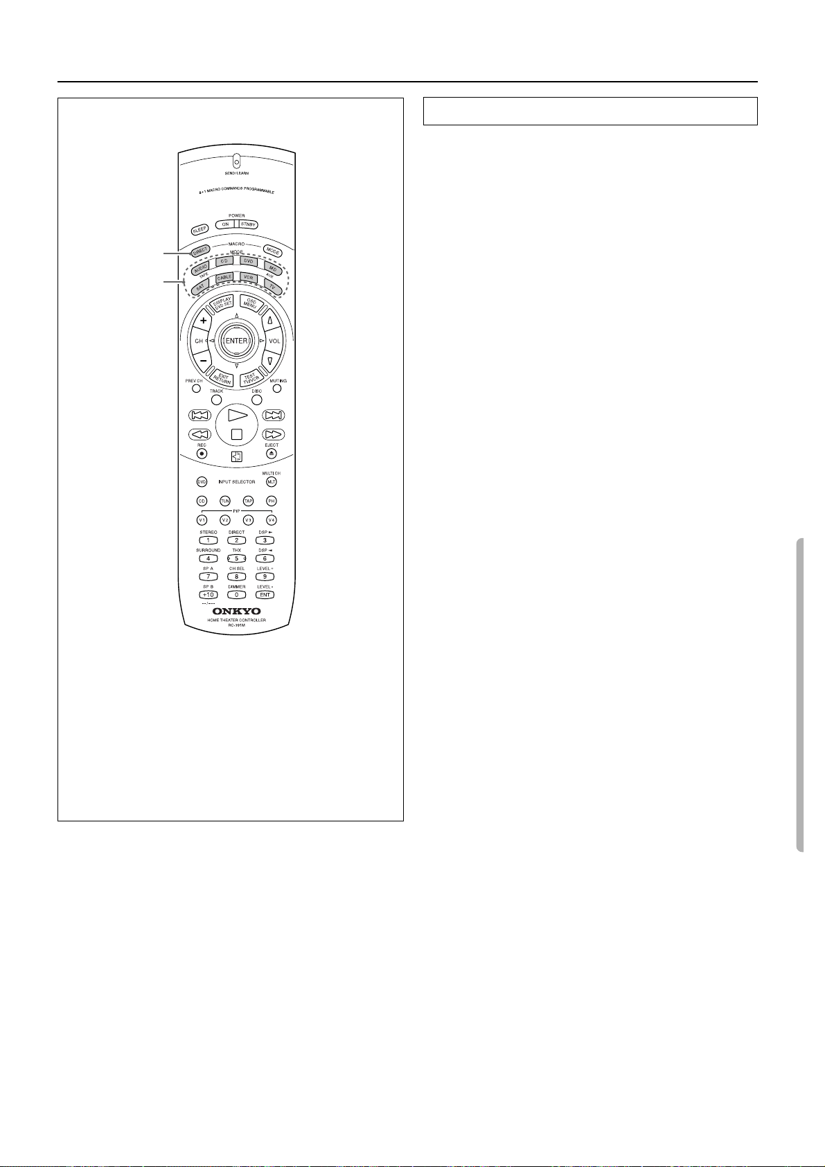
Using a Macro function
1, 3
1
Programming Macro Direct
A series of remote controller button operations can be memorized
into the MACRO DIRECT button for one-touch control.
Note:
You can program only one series of button operations into the
MACRO DIRECT button.
1. Press and hold down any one of the eight MODE buttons
and press the MACRO DIRECT button. Then, release the
buttons.
When you press the MODE button, the SEND/LEARN indicator lights up. When you press the MACRO DIRECT button, the
indicator turns off. When you release the buttons, the indicator
flashes briefly, then lights up again.
2. Follow Steps 2 in the “Programming Macro Mode” on page
36.
3. Press the MACRO DIRECT button to complete the procedure.
The SEND/LEARN indicator flashes twice slowly.
4. Check to see if the button has been programmed correctly.
Point the RC-391M toward the DTR-5 and press the MACRO
DIRECT button, and make sure that the device responds as programmed.
Transmitting the codes in Macro mode takes a while. During
transmission, point the remote controller toward the device to
be controlled.
Tip:
The codes programmed into a MACRO button will be
transmitted with an interval of 0.5 seconds. However,
some devices may not be able to complete one operation in 0.5 seconds and may miss the next code. In this
case, press one operation button, press the corresponding MODE button, then press another operation button
to extend the interval between the two operations up to
one second.
Note:
• You may program up to 16 button operations into the MACRO
DIRECT button. If you try to program the 17th step, it will be
ignored.
• If you do not press any button for more than 30 seconds during
the procedure, the SEND/LEARN indicator flashes three times
quickly, then the RC-391M exits Learning mode. Resume Step
1.
• If you make a mistak e during programming, the SEND/LEARN
indicator flashes three times quickly, then the RC-391M exits
Learning mode. Resume Step 1.
• If you erase one of the operation b uttons already programmed in
the MACRO DIRECT button, or if you program a different
code into such a button, the operation button will no longer
work. In this case, program the buttons again to avoid malfunction.
37
Page 38
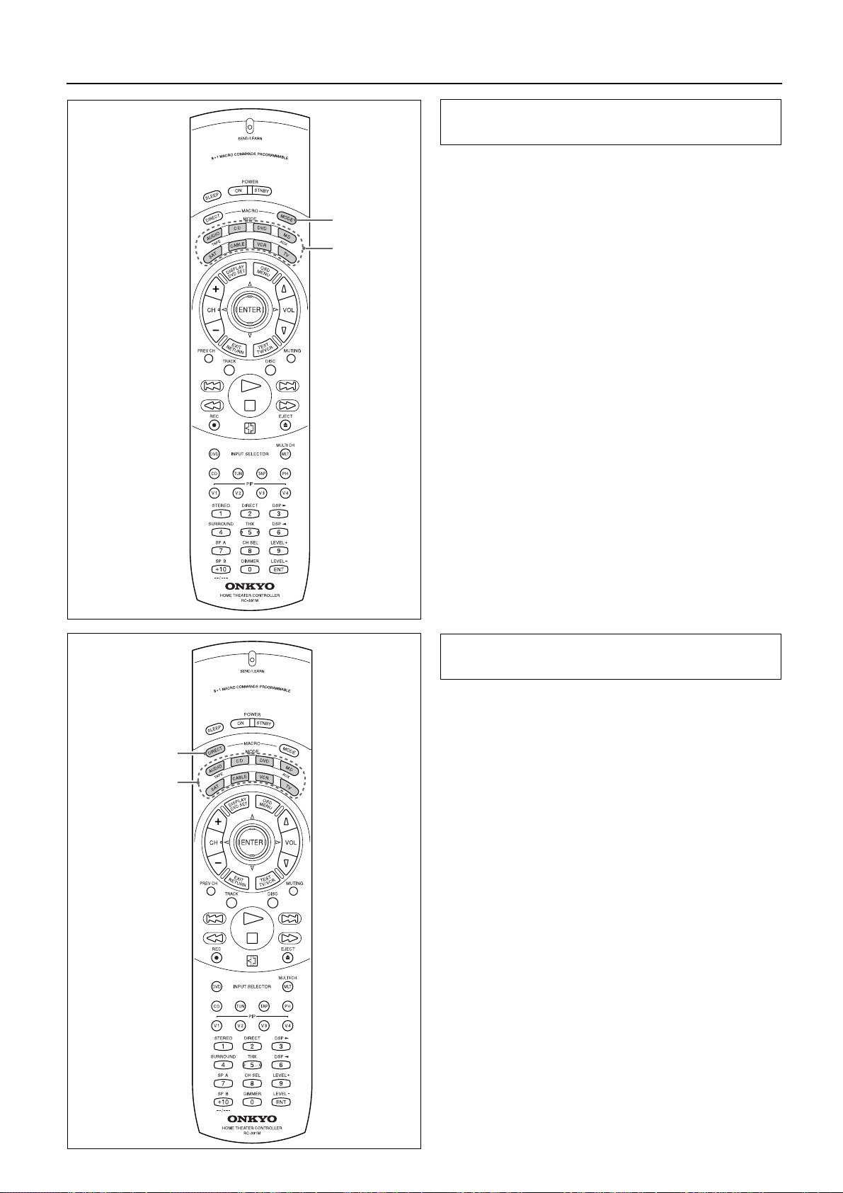
Using a Macro function
1, 2
1
Erasing a learned remote controller button operation from the MACRO MODE buttons
1. Press and hold down the corresponding MODE button and
press the MACRO MODE button, then release the buttons.
When you press the MODE button, the SEND/LEARN indicator lights up. When you press the MACRO MODE button, the
indicator turns off. When you release the buttons, the indicator
flashes once.
2. Press the MACRO MODE button again.
The SEND/LEARN indicator flashes twice slowly. The learned
operation is erased.
1, 2
1
Erasing a learned remote controller button operation from the MACRO DIRECT button
1. Press and hold down any one of the MODE buttons and
press the MACRO DIRECT button. Then release the buttons.
When you press the MODE button, the SEND/LEARN indicator lights up. When you press the MACRO DIRECT button, the
indicator turns off. When you release the buttons, the indicator
flashes once.
2. Press the MACRO DIRECT button again.
The SEND/LEARN indicator flashes twice slowly. The learned
operation is erased.
Note:
• If you do not press any button for more than 30 seconds, the
SEND/LEARN indicator flashes three times quickly, then the
RC-391M exits Learning mode. Resume Step 1.
• If you press a wrong b utton in Step 2, you may ha v e o v erwritten
the memory of the button you pressed.
38
Page 39
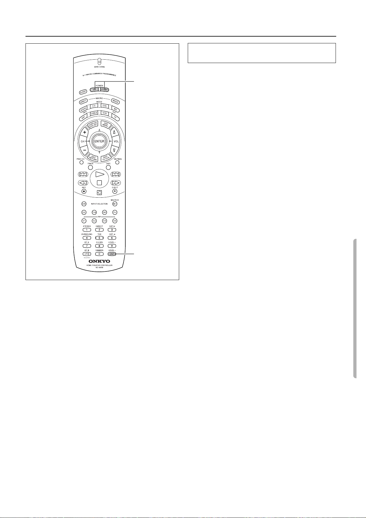
Using a Macro function
Erasing all codes and operations programmed
in the buttons
This procedure will erase all remote controller codes for the other
devices and all macro operations that have been programmed in the
2
RC-391M (see pages 34, 36 and 37).
1. Open the battery cover and remove the batteries.
2. While pressing and holding down the POWER ON button
and the POWER STNBY button, insert the batteries in the
correct direction.
After inserting the batteries, release the buttons. The SEND/
LEARN indicator flashes slowly.
3. Press the ENT button.
The SEND/LEARN indicator lights up for about ten seconds,
then turns off. All programmed codes are erased and the button
memories return to the factory presets.
Note:
• Proceed to Step 3 immediately after Step 2. Otherwise, the bat-
teries will be consumed quickly.
• If you press any button other than the ENT button in Step 3, no
codes will be erased. In this case, repeat the steps from the
beginning.
3
39
Page 40
Troubleshooting guide
If a problem occurs while you are using the remote controller, first try to operate the front panel controls on the main unit to make sure that it
is not due to a malfunction (or worn out batteries) in the remote controller.
Trouble Cause Remedy
No power. • Power cord is disconnected.
• There is external noise in the computer cir-
cuits of this unit.
• AC fuse blown.
Power on but no sound. • MUTING indicator is lit.
• The digital/analog input setting is incorrect.
• Bad connections.
• Amplifier protection circuitry has been acti-
vated. (‘PROTECT’ will be displayed.)
No sound from the center
speaker, or very minimal
sound.
• Speaker cable is not corrected.
• Listening mode is set to STEREO.
• CENTER level is set to minimum.
• CENTER SPEAKER is set to NONE.
Hum, low-frequency noise. • Poor or no input ground.
• Poor or no phono motor ground.
• The placement of the audio connection cables
on the rear panel is incorrect.
Howling when the volume is
turned up.
Rough or scratchy sound.
High range is not clear.
• Turntable and speakers are too close
together.
• Stylus of turntable pick-up is worn.
• Turntable stylus tip is dirty.
• Treble control too high.
AM stations cannot be
received.
Buzzing noise on AM (particularly conspicuous at night or
with weak stations).
High-pitched noise or buzzing
noise on AM.
Crackling noise on AM, FM. • Noise caused by turning fluorescent lamp on
• AM loop antenna is not attached. • Connect the included AM loop antenna to the
• Noise from electrical apparatus such as fluo-
rescent lamp.
• Noise from TV set. • Place the AM loop antenna as far as possible
and off.
• Noise from automobile ignition.
TUNED and STEREO indicators light but sound is distorted
and stereo separation is bad.
TUNED and STEREO indicators flicker and hiss is heard
on FM.
No station is recalled. • The power cord has been unplugged or the
Front panel controls function
but remote controller does not.
The sound of the playback
source is not heard.
• Station is too strong.
• Multiple reflection of the radio waves because
of tall buildings or mountains.
• Station is too weak.
• Stereo FM broadcasts cover only about half
the distance of an ordinary broadcast.
POWER switch has been turned off for a long
time.
• No batteries in remote controller.
• Batteries have worn out.
• The input selector is not set properly. • Set it to the playback source. 17
See
page
• Plug in the power cable into the AC outlet
securely. Make sure that the power cable is
not disconnected from the DTR-5.
• Tur n the power button off and then on again
or remove the AC plug from the outlet and
then plug it again.
11
• Contact your Onkyo Service Center.
• Press the MUTING button on the remote con-
troller to turn it off.
• Select the correct input.
• Check connections, speaker leads, etc.
20
18
10
• Contact your Onkyo Service Center.
• Check the connection between the amplifier
and the speaker.
• Set the Listening mode to any mode other
than STEREO.
• Set the CENTER level to the appropriate vol-
ume.
• Set CENTER SPEAKER to LARGE or SMALL.
10
22
15
14
• Check outer conductor of input plugs.
• Check for proper ground connection.
• Adjust the placement of the cable to reduce
hum.
• Move them farther apart.
• Replace.
• Clean.
• Turn treble control down. 20
12
AM antenna terminals.
• Move the AM loop antenna to different posi-
tion.
• Set up an outdoor AM antenna.
from the TV.
13
13
13
• Move unit away from TV set.
• Move antenna as far as possible from the flu-
orescent lamp.
• Install an FM outdoor antenna as far as possi-
ble from the road.
13
• Change the position or direction of the out-
door antenna.
• Change to FM indoor antenna.
• Use antenna which has better directivity and
select a point where the distortion is least.
• Install an outdoor FM antenna.
12
13
13
• Change the position or direction of the out-
door antenna.
• The memory contents are lost. Store all sta-
tions again.
23
• Insert batteries.
• Replace batteries.
9
6
6
5
5
Also refer to the respective instruction manuals of the video disc player, video cassette recorder, TV monitor, etc., that compose your entertainment system.
Because the unit contains a microcomputer to provide advanced functions, it may malfunction due to external noise or static electricity. If
this happens, press the POWER switch on the unit and then press it in again after about five seconds.
40
Page 41

Specifications
AMPLIFIER SECTION
Continuous Av erage Power
output (FTC)
All channels: 70 watts per channel min. RMS at
8 ohms, 2 channels driven from 20 Hz
to 20 kHz with no more than 0.08%
total harmonic distortion.
90 watts min. RMS at 6 ohms, 2 channels driven from 1 kHz with no more
than 0.1% total harmonic distortion.
Maximum Power output (EIAJ) 130 watts at 6 ohms
Total Harmonic Distortion: 0.08% at rated power (Front)
IM Distortion: 0.08% at rated power (Front)
Damping Factor: 60 at 8 ohms (Front)
Input Sensitivity and Impedance
PHONO: 2.5 mV, 50 kohms
LINE (CD, TAPE, DVD,
VIDEO 1, 2, 3): 200 mV, 50 kohms
MULTICHANNEL INPUT
(FRONT L/R, SUR-
ROUND L/R, CENTER): 200 mV, 50 kohms
(SUBWOOFER): 36 mV, 50 kohms
COAXIAL 1, 2 (DIGITAL): 0.5 Vp-p, 75 ohms
Output Level and Impedance
Rec out (TAPE, VIDEO 1): 200 mV, 2.2 kohms
Pre out (SUBWOOFER): 1 V, 2.2 kohms
Phono Overload: 70 mV RMS at 1 kHz, 0.5% T.H.D.
Frequency Response: 20 Hz to 100 kHz, +1/–3 dB
RIAA Deviation: 20 Hz to 20 kHz, ±0.8 dB
Tone Control
Bass: ±10 dB at 100 Hz
Treble: ±10 dB at 10 kHz
Signal-to-Noise Ratio
Phono: 80 dB (IHF A, 5 mV input)
CD/Tape: 100 dB (IHF A)
VIDEO SECTION
Input sensitivity/Impedance
(DVD, VIDEO 1, 2, 3)
VIDEO (Composite): 1 Vp-p, 75 ohms
Output Level/Impedance
(VIDEO 1, MONITOR)
VIDEO (Composite): 1 Vp-p, 75 ohms
IF Rejection Ratio: 90 dB
Signal-to-Noise Ratio
Mono: 76 dB
Stereo: 70 dB
Alternate Channel Attenuation: 55 dB
Selectivity: 50 dB (DIN)
AM Suppression Ratio: 50 dB
Total Harmonic Distortion
Mono: 0.2%
Stereo: 0.3%
Frequency Response: 30 Hz — 15 kHz, ±1.0 dB
Stereo Separation: 45 dB at 1 kHz
30 dB at 100 Hz — 10 kHz
AM
Tuning Range: 530—1,710 kHz (10 kHz steps)
Usable Sensitivity: 30 µV
Image Rejection Ratio: 40 dB
IF Rejection Ratio: 40 dB
Signal-to-Noise Ratio: 40 dB
Total Harmonic Distortion: 0.7%
GENERAL
Power Supply: AC 120 V, 60 Hz
Power Consumption: 3.9 A
325 W
Dimensions (W
Weight: 12.2 kg, 26.9 lbs.
REMOTE CONTROL
Transmitter: Infrared
Signal range: Approx. 5 meters, 16 ft.
Power supply: Two “AA” batteries (1.5 V
Specifications and features are subject to change without notice.
Power supply and voltage vary depending on the area in which the unit is
purchased.
× H × D): 435 × 175 × 390 mm
17-1/8" × 6-7/8" × 15-3/8"
× 2)
TUNER SECTION
FM
Tuning Range: 87.5 — 108.0 MHz
Usable Sensitivity
Mono: 11.2 dBf, 1.0 µV (75 ohms)
Stereo: 17.2 dBf, 2.0 µV (75 ohms)
50 dB Quieting Sensitivity
Mono: 17.2 dBf, 2.0 µV (75 ohms)
Stereo: 37.2 dBf, 20 µV (75 ohms)
Capture Ratio: 2.0 dB
Image Rejection Ratio: 40 dB
41
Page 42
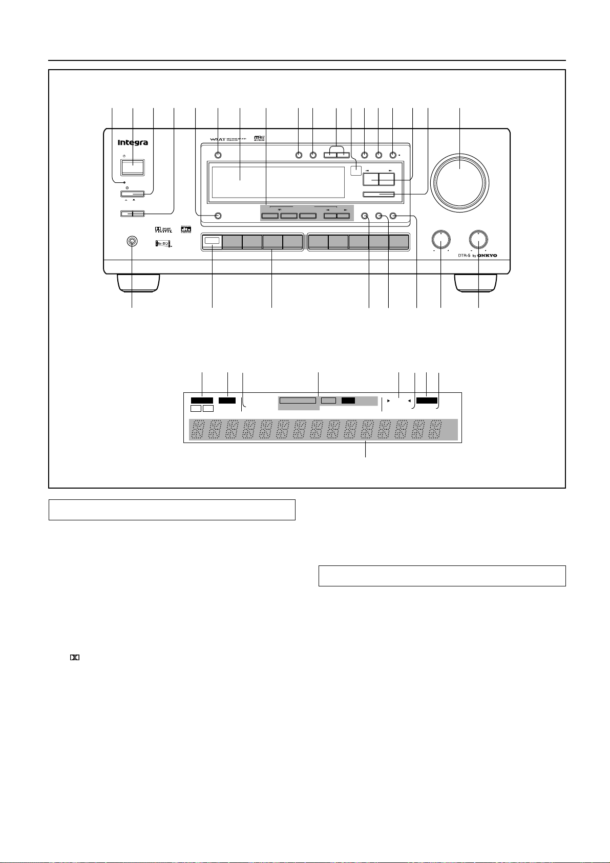
Control positions and names
2 6 9 10 13 14 15 1816 1712117 83 451
STANDBY/ON
SPEAKERSAB
Display
STANDBY
POWER
ON
PHONES
g
FM MUTE
MEMORY
BASS
20
h
MASTER VOLUME
RDS
f t
ch
dB
TREBLE
19
MUTE /
FM
/DTS
SURROUND
VIDEO 3
MEMORY
LISTENING MODE
CH STEREO
5
MODE
TAPEDVD
DIMMER
OFF
VIDEO 1
STEREO
VIDEO 2
DISPLAY
CH
MULTI
INPUT
TUNING
DSP
FM
DIGITAL/
ANALOG
UPDOWN
PRESET / MODE ADJ
LATE
NIGHT /
FRONT
EFFECT
AM PHONO C
SP / SYS
CH LEVEL
SETUP
DOW NUP
ENTER / SCAN
LFE LEVEL
CONTROL
Re -EQ
MODE
D
242526 212223
a
SPEAKERS
AB
b
SLEEP
AUTO
STANDBY
c
PC M DIGITAL
MPEG
DOLBY
PRO LOGIC
d
DTS
ALDOLBY DIGIT
DS P
STEREO
DIRECT
e
TUNED
FM STEREO
f
Front panel
For more information about buttons or knobs, refer to the pages listed
in the brackets ( [ ] ) below.
1. STANDBY indicator [5, 11]
2. STANDBY/ON button[9, 11]
3. POWER switch [9, 11]
4. SPEAKERS A/B button [17, 20]
5. DISPLAY button [24]
6. DIMMER button [17]
7. Display (Refer to the “Display” illustration.)
8. LISTENING MODE buttons
STEREO button [22]
/DTS SURROUND button [22]
5 CH STEREO button [22]
DSP √/® (DOWN/UP) buttoun [22]
9. MEMORY button [25]
10. FM MUTE/MODE button [24]
11. TUNING UP/DOWN buttons [24]
12. Remote control sensor [5]
13. DIGITAL/ANALOG button [18]
14. SP/SYS SETUP button [14, 15]
15. CH LEVEL button [23]
16. PRESET/MODE ADJ √/® button [14, 15, 18, 25]
17. ENTER/SCAN button [14, 15, 18, 25, 26]
18. MASTER VOLUME control knob [17, 20]
19. TREBLE control knob [17, 20]
20. BASS control knob [17, 20]
21. LEF LEVEL CONTROL button [23]
42
i
22. Re-EQ button [23]
23. LATE NIGHT/FRONT EFFECT button [23]
24. Input selector buttons [17, 22, 27]
25. MULTI CHANNEL INPUT button [17, 19]
26. PHONES jack [20]
Display
If a protective film on the surface of the screen making it difficult
to read the display, remove the film.
a. Speakers A/B indicators
b. Sleep indicator
c. PCM digital indicator
d. Listening mode indicators
e. Tuned indicators
f. FM Stereo indicator
g. FM Mute On/Off indicator
h. Memory indicator
i. Multi function display
(Frequency and Preset station/Input selector/Sleep time/
Volume level/Listening mode)
Page 43
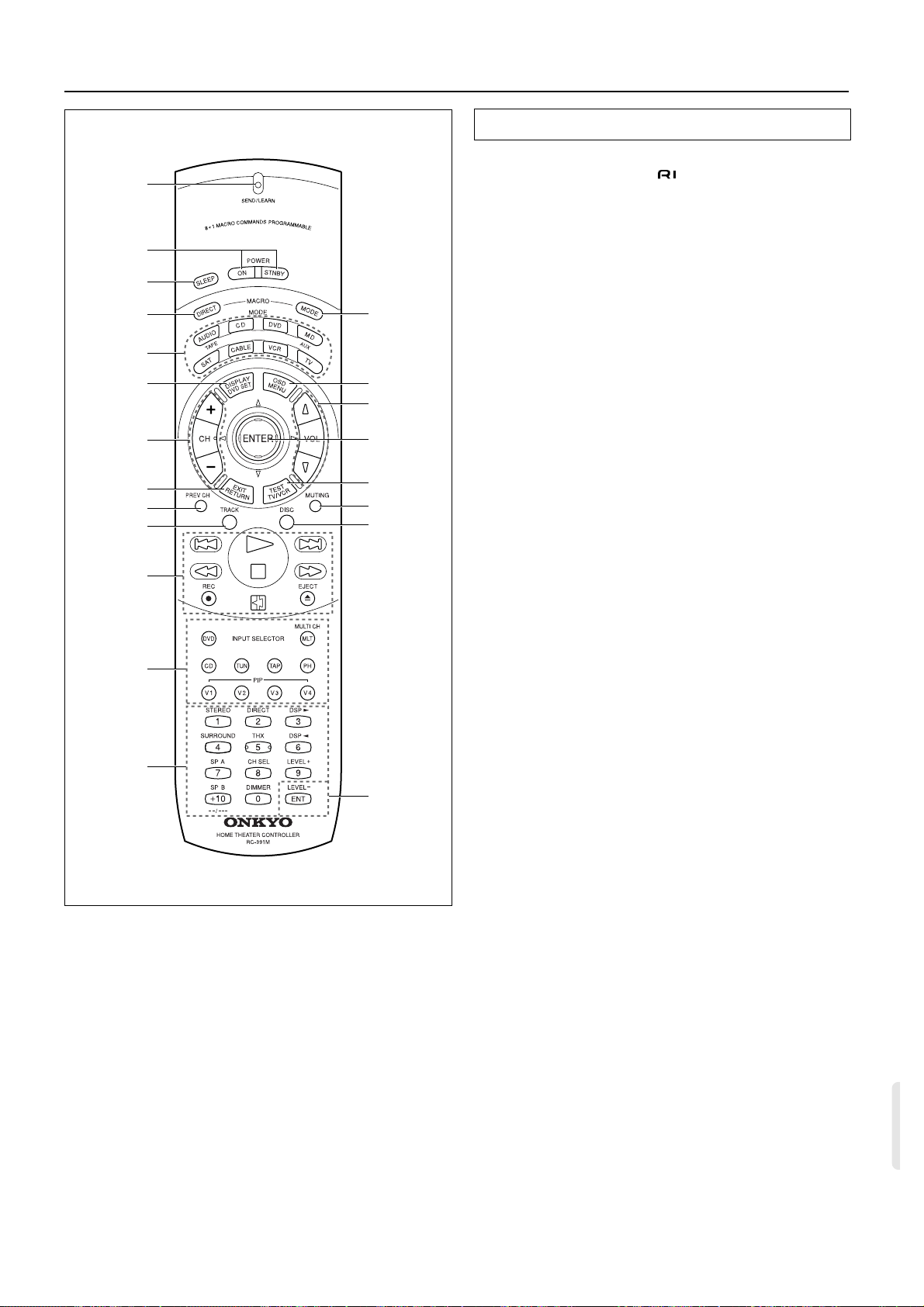
Control positions and names
1
2
3
4
5
6
7
8
9
10
11
12
13
21
20
19
18
17
16
15
14
Remote controller
Using the remote controller, you can control a CD player or cassette tape deck connected to the connector of the DTR-5. (See
page 9 for more information.)
1. SEND/LEARN indicator [31]
2. POWER ON/STNBY button [31]
Power on/Standby on
3. SLEEP button [20]
Sleep function button
4. MACRO DIRECT button [37]
Macro Direct function
5. MODE buttons [31~39]
6. DISPLAY/DVD SET button [32]
7. CH +/– buttons [31]
8. EXIT/RETURN button [32]
9. PREV CH button [This button is not used for the
DTR-5.]
10. TRACK button [32]
11. CD/TAPE/DVD/MD operation buttons [31~33]
12. Input Selector buttons [17]
The V4 button is not used for the DTR-5.
13. Numeric key/STEREO/DSP√, ®/SURROUND/SP
A, B/CH SEL/LEVEL+,–/DIMMER buttons
[31~33]
[The DIRECT button and THX* button are not used for the
DTR-5.]
14. ENT button [34, 35, 39]
15. DISC button [32]
16. MUTING button [20]
Mute button
17. TEST/TV/VCR button [16]
18. ENTER/cursor buttons [32]
19. VOLq/u button [17]
Volume adjustment
20. OSD/MENU button [32]
21. MACRO MODE button [36]
*The THX® button activates the THX mode on products certified by
Lucasfilm.
This control will not function on products which are not THX-certified.
THX is a registered trademark of Lucasfilm, Ltd.
43
Page 44

Sales & Product Planning Div. : 2-1, Nisshin-cho, Neyagawa-shi, OSAKA 572-8540, JAPAN
Tel: 0720-31-8111 Fax: 0720-33-5222
ONKYO U.S.A. CORPORATION
200 Williams Drive, Ramesy, N.J. 07446, U.S.A.
Tel: 201-825-7950 Fax: 201-825-8150 E-mail: [email protected]
ONKYO EUROPE ELECTRONICS GmbH
Industriestrasse 20, 82110 Germering, GERMANY
Tel: 089 84 93 20 Fax: 089 84 93 226 E-mail: [email protected]
ONKYO CHINA LIMITED
Units 2102-7, Metroplaza Tower I, 223 Hing Fong Road, Kwai Chung,
N.T., HONG KONG Tel: 852 2429 3118 Fax: 852 2428 9039
HOMEPAGE
http://www.onkyo.co.jp/
44
SN 29342704
I9905-1
E
 Loading...