

Integra DTC-9.4 Owners manual

Contents
AV Controller
DTC-9.4
Instruction Manual
Before using 2
Facilities and connections 10
Setup and operation 31
Thank you for purchasing the AV
Controller. Please read this manual thoroughly
before making connections and plugging in the
unit. Following the instructions in this manual will
enable you to obtain optimum performance and
listening enjoyment from your new AV Controller.
Please retain this manual for future reference.
Remote controller 72
Appendix 90
E
WARNING:
TO REDUCE THE RISK OF FIRE OR ELECTRIC SHOCK,
DO NOT EXPOSE THIS APPLIANCE TO RAIN OR
MOISTURE.
CAUTION:
TO REDUCE THE RISK OF ELECTRIC SHOCK, DO NOT
REMOVE COVER (OR BACK). NO USER-SERVICEABLE
PARTS INSIDE. REFER SERVICING TO QUALIFIED
SERVICE PERSONNEL.
Important Safeguards
WARNING
RISK OF ELECTRIC SHOCK
DO NOT OPEN
The lightning flash with arrowhead symbol, within an equilateral
triangle, is intended to alert the user to the presence of uninsulated
“dangerous voltage” within the product’s enclosure that may be of
sufficient magnitude to constitute a risk of electric shock to persons.
The exclamation point within an equilateral triangle is intended to
alert the user to the presence of important operating and maintenance
(servicing) instructions in the literature accompanying the appliance.
AVIS
RISQUE DE CHOC ELECTRIQUE
OUVRIR
NE PAS
1. Read Instructions – All the safety and operating instructions
should be read before the appliance is operated.
2. Retain Instructions – The safety and operating instructions
should be retained for future reference.
3. Heed Warnings – All warnings on the appliance and in the
operating instructions should be adhered to.
4. Follow Instructions – All operating and use instructions
should be followed.
5. Cleaning – Unplug the appliance from the wall outlet before
cleaning. The appliance should be cleaned only as recommended by the manufacturer.
6. Attachments – Do not use attachments not recommended by
the appliance manufacturer as they may cause hazards.
7. Water and Moisture – Do not use the appliance near water –for
example, near a bath tub, wash bowl, kitchen sink, or laundry
tub; in a wet basement; or near a swimming pool; and the like.
8. Accessories – Do not place the appliance on an unstable cart,
stand, tripod, bracket, or table. The appliance may fall, causing
serious injury to a child or adult, and serious damage to the
appliance. Use only with a cart, stand, tripod, bracket, or table
recommended by the manufacturer, or sold with the appliance.
Any mounting of the appliance should follow the
manufacturer’s instructions, and
should use a mounting accessory
recommended by the manufacturer.
9. An appliance and cart combination should be moved with care.
Quick stops, excessive force, and
uneven surfaces may cause the
appliance and cart combination to
overturn.
10. Ventilation – Slots and openings in the cabinet are provided
for ventilation and to ensure reliable operation of the appliance
and to protect it from overheating, and these openings must not
be blocked or covered. The openings should never be blocked
by placing the appliance on a bed, sofa, rug, or other similar
surface. The appliance should not be placed in a built-in installation such as a bookcase or rack unless proper ventilation is
provided. There should be free space of at least 20 cm (8 in.)
and an opening behind the appliance.
11. Power Sources – The appliance should be operated only from
the type of power source indicated on the marking label. If you
are not sure of the type of power supply to your home, consult
your appliance dealer or local power company.
12. Grounding or Polarization – The appliance may be equipped
with a polarized alternating current line plug (a plug having one
blade wider than the other). This plug will fit into the power
outlet only one way. This is a safety feature. If you are unable to
insert the plug fully into the outlet, try reversing the plug. If the
plug should still fail to fit, contact your electrician to replace
your obsolete outlet. Do not defeat the safety purpose of the
polarized plug.
PORTABLE CART WARNING
S3125A
13. Power-Cord Protection – Power-supply cords should be
routed so that they are not likely to be walked on or pinched by
items placed upon or against them, paying particular attention
to cords at plugs, convenience receptacles, and the point where
they exit from the appliance.
14. Outdoor Antenna Grounding – If an outside antenna or cable
system is connected to the appliance, be sure the antenna or
cable system is grounded so as to provide some protection
against voltage surges and built-up static charges. Article 810
of the National Electrical Code, ANSI/NFPA 70, provides information with regard to proper grounding of the mast and supporting structure, grounding of the lead-in wire to an antennadischarge unit, size of grounding conductors, location of antenna-discharge unit, connection to grounding electrodes, and
requirements for the grounding electrode. See Figure 1.
15. Lightning – For added protection for the appliance during a
lightning storm, or when it is left unattended and unused for
long periods of time, unplug it from the wall outlet and disconnect the antenna or cable system. This will prevent damage to
the appliance due to lightning and power-line surges.
16. Power Lines – An outside antenna system should not be lo-
cated in the vicinity of overhead power lines or other electric
light or power circuits, or where it can fall into such power lines
or circuits. When installing an outside antenna system, extreme
care should be taken to keep from touching such power lines or
circuits as contact with them might be fatal.
17. Overloading – Do not overload wall outlets, extension cords,
or integral convenience receptacles as this can result in a risk
of fire or electric shock.
18. Object and Liquid Entry – Never push objects of any kind
into the appliance through openings as they may touch dangerous voltage points or short-out parts that could result in a fire or
electric shock. Never spill liquid of any kind on the appliance.
19. Servicing – Do not attempt to service the appliance yourself as
opening or removing covers may expose you to dangerous voltage or other hazards. Refer all servicing to qualified service
personnel.
20. Damage Requiring Service – Unplug the appliance form the
wall outlet and refer servicing to qualified service personnel
under the following conditions:
A. When the power-supply cord or plug is damaged,
B. If liquid has been spilled, or objects have fallen into the
appliance,
C. If the appliance has been exposed to rain or water,
D. If the appliance does not operate normally by following the
operating instructions. Adjust only those controls that are
covered by the operating instructions as an improper ad-
justment of other controls may result in damage and will
often require extensive work by a qualified technician to
restore the appliance to its normal operation,
E. If the appliance has been dropped or damaged in any way,
and
F. When the appliance exhibits a distinct change in perfor-
mance – this indicates a need for service.
2
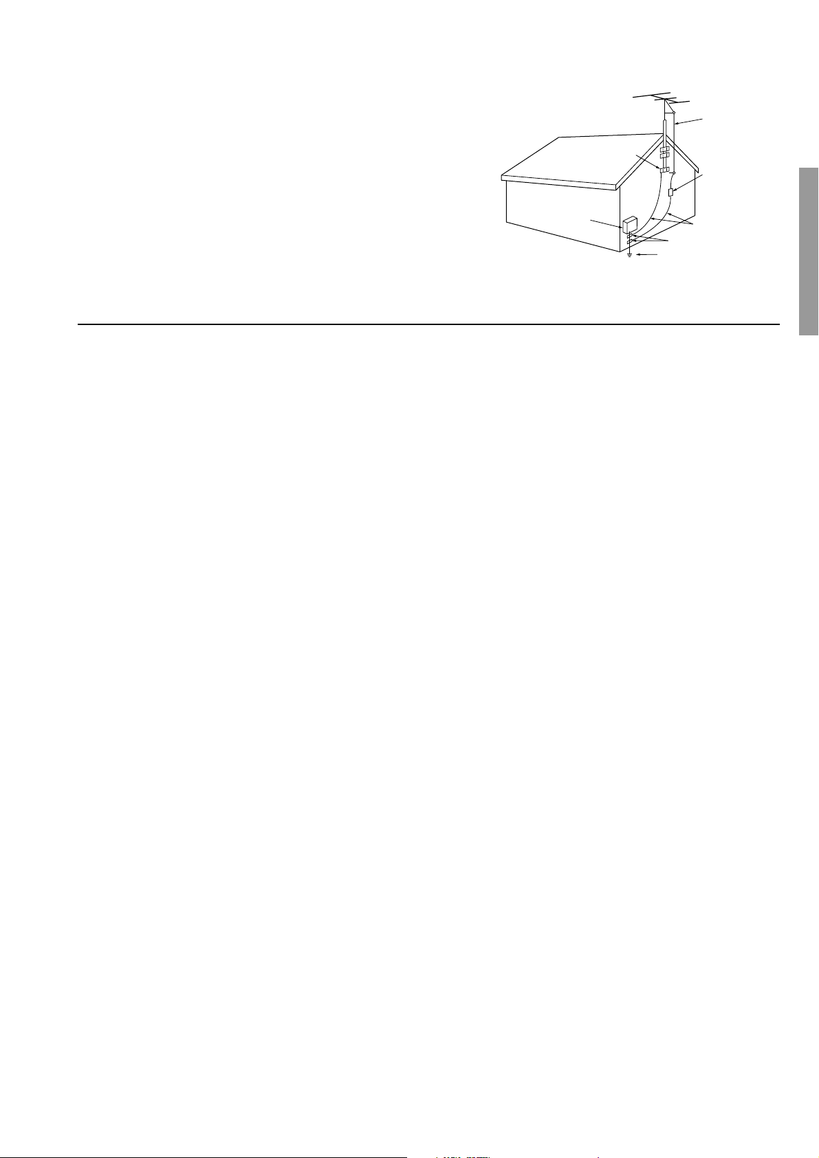
ANTENNA
DISCHARGE UNIT
(NEC SECTION 810-20)
GROUNDING CONDUCTORS
(NEC SECTION 810-21)
GROUND CLAMPS
POWER SERVICE GROUNDING
ELECTRODE SYSTEM
(NEC ART 250, PART H)
NEC – NATIONAL ELECTRICAL CODE
ELECTRIC
SERVICE
EQUIPMENT
GROUND
CLAMP
ANTENNA
LEAD IN
WIRE
S2898A
21. Replacement Parts – When replacement parts are required, be
sure the service technician has used replacement parts specified
by the manufacturer or have the same characteristics as the
original part. Unauthorized substitutions may result in fire,
electric shock, or other hazards.
22. Safety Check – Upon completion of any service or repairs to the
appliance, ask the service technician to perform safety checks to
determine that the appliance is in proper operation condition.
23. Wall or Ceiling Mounting – The appliance should be mounted
to a wall or ceiling only as recommended by the manufacturer.
24. Heat – The appliance should be situated away from heat
sources such as radiators, heat registers, stoves, or other appliances (including amplifiers) that produce heat.
25. Liquid Hazards – The appliance shall not be exposed to dripping or splashing and no objects filled with liquids, such as
vases shall be placed on the appliance.
Precautions
FIGURE 1:
EXAMPLE OF ANTENNA GROUNDING AS PER NATIONAL
ELECTRICAL CODE, ANSI/NFPA 70
1. Recording Copyright
Recording of copyrighted material for other than personal use is
illegal without permission of the copyright holder.
2. AC Fuse
The fuse is located inside the chassis and is not user-serviceable. If power
does not come on, contact your Onkyo authorized service station.
3. Care
From time to time you should wipe the front and rear panels and the
cabinet with a soft cloth. For heavier dirt, dampen a soft cloth in a
weak solution of mild detergent and water, wring it out dry, and
wipe off the dirt. Following this, dry immediately with a clean
cloth. Do not use rough material, thinners, alcohol or other chemical solvents or cloths since these could damage the finish or remove
the panel lettering.
4. Power
WARNING
BEFORE PLUGGING IN THE UNIT FOR THE FIRST TIME,
READ THE FOLLOWING SECTION CAREFULLY.
The voltage of the available power supply differs according to
country or region. Be sure that the power supply voltage of the area
where this unit will be used meets the required voltage (e.g., AC
230 V, 50 Hz or AC 120 V, 60 Hz) written on the rear panel.
For U.S. models
Note to CATV system installer:
This reminder is provided to call the CATV system installer’s attention to Section 820-40 of the NEC which provides guidelines for
proper grounding and, in particular, specifies that the cable ground
shall be connected to the grounding system of the building, as close
to the point of cable entry as practical.
FCC INFORMATION FOR USER
CAUTION:
The user changes or modifications not expressly approved by the
party responsible for compliance could void the user’s authority to
operate the equipment.
NOTE:
This equipment has been tested and found to comply with the limits
for a Class B digital device, pursuant to Part 15 of the FCC Rules.
These limits are designed to provide reasonable protection against
harmful interference in a residential installation. This equipment
generates, uses and can radiate radio frequency energy and, if not
installed and used in accordance with the instructions, may cause
harmful interference to radio communications. However, there is
no guarantee that interference will not occur in a particular installation. If this equipment does cause harmful interference to radio or
television reception, which can be determined by turning the equipment off and on, the user is encouraged to try to correct the interference by one or more of the following measures:
• Reorient or relocate the receiving antenna.
• Increase the separation between the equipment and receiver.
• Connect the equipment into an outlet on a circuit different from
that to which the receiver is connected.
• Consult the dealer or an experienced radio/TV technician for
help.
For Canadian models
NOTE: THIS CLASS B DIGITAL APPARATUS COMPLIES
WITH CANADIAN ICES-003.
For models having a power cord with a polarized plug:
CAUTION: TO PREVENT ELECTRIC SHOCK, MATCH
WIDE BLADE OF PLUG TO WIDE SLOT, FULLY INSERT.
Modèle pour les Canadien
REMARQUE: CET APPAREIL NUMÉRIQUE DE LA
CLASSE B EST CON-FORME À LA NORME NMB-003 DU
CANADA.
Sur les modèles dont la fiche est polarisée:
ATTENTION: POUR ÉVITER LES CHOCS ÉLECTRIQUES,
INTRODUIRE LA LAME LA PLUS LARGE DE LA FICHE
DANS LA BORNE CORRESPONDANTE DE LA PRISE ET
POUSSER JUSQU’AU FOND.
3

Contents
Before using
Important Safeguards......................................... 2
Precautions ......................................................... 3
Contents .............................................................. 4
Features ...............................................................6
Supplied accessories ......................................... 7
Before using this unit......................................... 7
Connecting the power cord .............................................. 7
Using the remote controller.............................................. 7
Setting up the remote controller ....................... 8
Insert batteries .................................................................. 8
Characterizing the remote controller ............................... 8
Touch the screen to start................................................... 9
Facilities and connections
Index parts and facilities.................................. 10
Front panels .................................................................... 10
Front panel display ......................................................... 12
Rear panel ....................................................................... 13
Remote controller ........................................................... 14
Connecting to Audio/Video equipment ..........16
Connecting your audio components .............................. 17
Connecting your video components .............................. 18
Speaker Configuration and placement........... 22
Ideal speaker configuration ............................................ 22
Minimum speaker configuration for surround sound
playback .................................................................. 22
Speaker placement .......................................................... 22
Connecting antennas ....................................... 23
Assembling the AM loop antenna.................................. 23
Connecting the AM antenna cable ................................. 23
Connecting the included antennas ................................. 23
Connecting an FM outdoor antenna............................... 24
Connecting an AM outdoor antenna .............................. 24
Directional linkage ......................................................... 24
Connecting devices used in Zone 2 ............... 25
When using the ZONE 2 OUT terminals....................... 25
When using the SURR BACK/ZONE 2 PRE OUT
terminals .................................................................. 25
Operating components not reached by the
remote controller signals (IR IN/OUT) ....... 26
If the remote controller signal does not reach the
DTC-9.4 remote sensor ........................................... 26
If the remote controller signal does not reach other
components ............................................................. 26
Miscellaneous Connections ............................ 27
Connections for remote control ( ) ............................ 27
Connecting the power cords from other devices ........... 27
RS232 port ...................................................................... 27
Connecting to devices with analog multi channel output........
Connecting to an external device with 12V TRIGGER
terminal ................................................................... 28
Connecting auxiliary power amplifiers with RCA type
connector ................................................................. 28
28
Connecting power amplifiers with XLR type connector .........
Connecting the power ...................................... 30
Turning on the power ..................................................... 30
Turning on the power from the remote controller ......... 30
To change the display of the input source from TAPE to MD .....
Setup and operation
Enjoying music or videos with the DTC-9.4 .... 31
Basic operation ............................................................... 31
Adjusting the bass and treble ......................................... 31
Listening with headphones............................................. 31
Changing the listening mode.......................................... 32
Switching the display ..................................................... 33
Using the Dolby Headphone function ........................... 33
Adjusting the brightness of the front display ................ 34
Temporarily changing the speaker output levels ........... 34
Using the sleep time (remote controller only) ............... 34
Temporarily turning off the sound ................................. 34
Changing the audio mode............................................... 35
Enjoying the multichannel output .................................. 35
Listening to Radio Broadcasts........................ 36
Tuning into a radio station ............................................. 36
Listening to a stereo radio station (FM mode) .............. 36
Presetting a radio station ................................................ 37
Selecting a preset radio station ...................................... 37
Erasing a preset radio station ......................................... 37
Recording a source .......................................... 38
To record the input source signal you are currently
watching or listening to .......................................... 38
To record an input source signal different from that you
are currently watching or listening to..................... 38
Recording the video from one source and the audio
from another ............................................................ 39
Enjoying music or videos in the remote zone .....
Using the buttons on the DTC-9.4 ................................. 40
Selecting an input source using the remote controller ....
Adjusting the volume for the remote zone .................... 41
How to Enjoy Net Audio ................................... 42
System Requirements ..................................................... 42
Connecting the DTC-9.4 to your Ethernet Network ..... 43
Enjoying Internet radio .................................................. 44
Playing a music file saved on the Audio Network Server .......
How to Enjoy Net Audio (Configuring Various
Settings) ....................................................... 47
Input Setup Menu (When Net Audio is selected as
the input source) ..................................................... 47
Network Setup Menu ..................................................... 47
Troubleshooting for Net Audio ...................................... 49
Specifications ................................................................. 49
Setup Menu........................................................ 50
Navigating through the Setup Menu .............................. 51
Hardware Setup................................................. 52
0. Hardware Setup Menu ............................................. 52
0-1. Surr Back/Zone 2 Sub-menu .................................. 52
0-2. IR IN Setup Sub-menu............................................ 52
29
30
40
41
45
4

Contents
Speaker Setup ................................................... 53
1. Speaker Setup Menu ................................................ 53
1-1. Speaker Config Sub-menu ...................................... 53
1-2. Speaker Distance Sub-menu ................................... 54
1-3. Level Calibration Sub-menu ................................... 55
1-4. THX Audio Setup Sub-menu .................................. 56
Input Setup ........................................................57
2. Input Setup Menu..................................................... 57
2-1. Digital Setup Sub-menu (When Net Audio is not
selected as the input source) ................................... 57
2-2. Multichannel Setup Sub-menu (When Net Audio is
not selected as the input source) ............................. 58
2-3. Video Setup Sub-menu ........................................... 59
2-4. Character Input Sub-menu ...................................... 59
2-5. IntelliVolume Sub-menu ......................................... 60
2-6. Listening Mode Preset Sub-menu .......................... 60
2-7. 12V Trigger Setup Sub-menu ................................. 60
Audio Adjust...................................................... 64
3. Audio Adjust Menu .................................................. 64
3-1. Tone Control Sub-menu .......................................... 64
3-2. Surround Speakers Sub-menu ................................ 64
3-3. Sound Effect Sub-menu .......................................... 65
3-4. Delay Sub-menu...................................................... 65
3-5. LFE Level Sub-menu .............................................. 66
3-6. Mono Sub-menu...................................................... 66
3-7. Theater-Dimensional Sub-menu ............................. 66
3-8. Surround Sub-menu ................................................ 67
3-9. THX Sub-menu ....................................................... 68
3-10. 3-11. 3-12. 3-13. 3-14. 3-15. Mono Movie/
Enhanced 7/Orchestra/Unplugged/Studio Mix /TV
Logic Sub-menu ...................................................... 68
Preference ......................................................... 70
4. Preference Menu ....................................................... 70
4-1. Volume Setup Sub-menu ........................................ 70
4-2. Headphones Level Sub-menu ................................. 71
4-3. OSD Setup Sub-menu ............................................. 71
4-4. OSD Position Sub-menu ......................................... 71
Moving menu items ........................................................ 81
Delete and Restore ........................................... 82
Delete .............................................................................. 82
Restore ............................................................................ 82
Recording Macros and Setting Timers ........... 83
Recording macros ........................................................... 83
Editing macros ................................................................ 83
Setting timers .................................................................. 84
Organizing macros and timers into groups .................... 84
Using the remote controller with Radio
Frequency..................................................... 85
Changing the remote controller’s RF IR Settings ......... 85
Choosing Another Channel ............................................ 86
Additional information ..................................... 87
ChadEdit ......................................................................... 87
Optional recharging dock ............................................... 87
FAQ .....................................................................88
Overview of Symbols ....................................... 89
Appendix
Troubleshooting guide ..................................... 90
POWER .......................................................................... 90
SPEAKERS .................................................................... 90
FM/AM TUNER............................................................. 90
VIDEO and AUDIO ....................................................... 91
OTHER ........................................................................... 91
REMOTE CONTROLLER ............................................ 92
If one of the messages shown below appears ................ 93
Specifications ................................................... 94
Remote controller
Using the Remote Controller ........................... 72
Adjust the Settings ......................................................... 72
Working with Modes ...................................................... 73
Selecting a Device .......................................................... 74
Define the Brand of Your Device .....................75
Define the Brand of Your Device ................................... 75
Defining brands by searching ........................................ 77
Programming Buttons ...................................... 78
Programming control panel buttons ............................... 78
Programming device items............................................. 79
Programming direct-access and Left/Right Buttons ..... 79
Labeling Buttons and Menu Items .................. 80
Labeling a button ............................................................ 80
Labeling a menu item ..................................................... 80
Adding and Moving Devices............................ 81
Adding devices ............................................................... 81
Adding macros................................................................ 81
5

Features
■ Linear Optimum Gain Volume Circuitry
■ 192 kHz/24 Bit D/A Converters
■ 12V Trigger
■ THX
®
Surround EX
®
■ THX Ultra2 Certified
■ Dolby
®*
Digital, Dolby Pro Logic II, Dolby Digital
EX
■ DTS, DTS-ES Discrete 6.1, DTS-ES Matrix 6.1,
DTS Neo:6, and DTS 96/24
■ Dolby Headphone
■ Theater-Dimensional
TM
Virtual Surround Mode
■ Non-Scaling Configuration
■ Onscreen displays (Basic Menu/Advanced Menu)
■ Composite to S-Video Conversion
■ 6 S-Video Inputs/3 Outputs
■ Crossover Adjustment (40 Hz, 60 Hz, 80 Hz, 100
Hz, 120 Hz)
■ 7 Assignable Digital Inputs (4 optical/3 coaxial), 2
outputs, and 1 Digital Input (optical)
■ 8 Balanced XLR Outputs for Front L/R, Center,
Surround L/R, Surround back L/R or Zone 2 L/R
and Subwoofer
■ 40 FM/AM random presets
■ FM auto tuning
■ IntelliVolume
■ Character Input
■ VLSC (Vector Linear Shaping Circuitry)
■ Net-Tune Function with MP3/WAVE (PCM)/
WMA Decoding
■ Ethernet cable plug-In Capability
■ Unique and fully customizable universal
touchscreen remote controller
* Manufactured under license from Dolby Laboratories.
“Dolby,” “Pro Logic,” “Surround EX” and the double-D symbol are
trademarks of Dolby Laboratories.
•“Theater-Dimensional” is a trademark of Onkyo Corporation.
•“Net-Tune” is a trademark of Onkyo Corporation.
• Ultra2 and THX are trademarks or registered trademarks of THX Ltd.
• Re-Equalization and the “Re-EQ” logo are trademarks of THX Ltd.
•“DTS,” “DTS-ES Extended Surround” and “Neo:6” are trademarks of
Digital Theater Systems, Inc.
• Windows Media, and the Windows logo are trademarks,
or registered trademarks of Microsoft Corporation in the
United States and/or other countries.
• Intel and Pentium are registered trademarks of Intel Corporation.
• MPEG Layer-3 audio coding technology licensed from Fraunhofer IIS
and THOMSON multimedia.
•“XiVA” is a registered trademark of Imerge Limited.
• Xantech is a registered trademark of Xantech Corporation.
• Niles is a registered trademark of Niles Audio Corporation.
THX Ultra2
Before any home theatre component can be THX Ultra2
certified, it must pass a rigorous series of quality and
performance tests. Only then can a product feature the THX
Ultra2 logo, which is your guarantee that the Home Theatre
products you purchase will give you superb performance for
many years to come. THX Ultra2 requirements define
hundreds of parameters, including power amplifier
performance, and pre-amplifier performance and operation
for both digital and analog domains. THX Ultra2 receivers
also feature proprietary THX technologies (e.g., THX Mode,
see page 63) which accurately translate film soundtracks for
home theater playback.
6
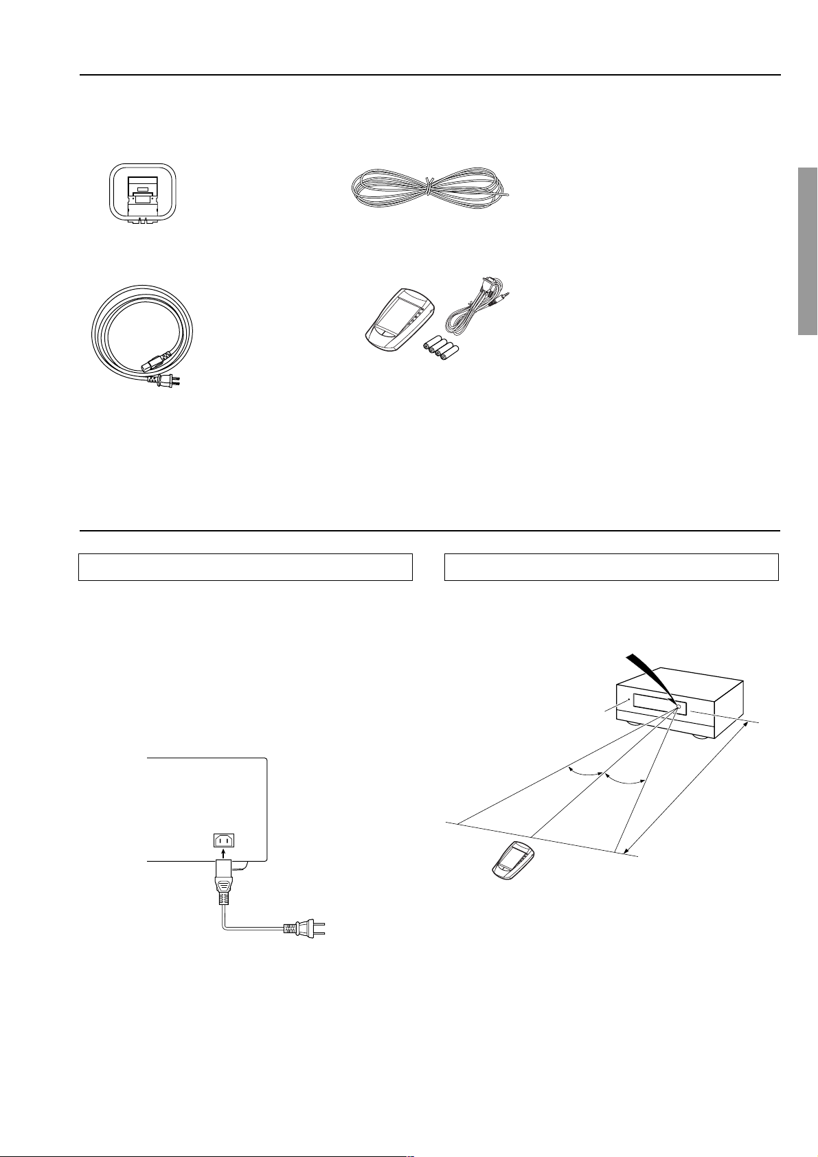
Supplied accessories
Check that the following accessories are supplied with the DTC-9.4.
AM loop antenna × 1
Power cord × 1
FM indoor antenna × 1
Remote controller × 1
Batteries (AA or R6) × 4
RS232 cable for PC connection × 1
Before using this unit
Connecting the power cord
Plug the supplied power cord into this AC INLET.
• Do not use a power cord other than the one supplied with the
DTC-9.4. The power cord supplied is designed for use with the
DTC-9.4 and should not be used with any other device.
• Never have the power cord disconnected from the DTC-9.4
while the other end is plugged into the wall outlet. Doing so may
cause an electric shock. Always connect by plugging into the
wall outlet last and disconnect by unplugging from the wall
outlet first.
Using the remote controller
Point the remote controller toward the remote control sensor. The
Standby indicator lights up when the unit receives a signal from the
remote controller.
Remote control sensor
Standby indicator
DTC-9.4
Power cord
(supplied)
30˚
AC INLET
Notes:
• Make sure that the remote control sensor is not subject to strong
light such as direct sunlight or inverted fluorescent light for it
may prevent proper operation of the remote controller.
DO NOT connect
the power cord at
this time.
• Using another remote controller in the same room or using the
DTC-9.4 near equipment that uses infrared rays may cause
operational interference.
• Do not put objects on the remote controller. Its buttons may be
pressed by mistake and drain the batteries.
• Make sure the audio rack doors do not have colored glass.
Placing the DTC-9.4 behind such doors may prevent proper
remote controller operation.
• If there is any obstacle between the remote controller and the
remote control sensor, the remote controller will not operate.
30˚
Approx. 16 feet
7
Setting up the remote controller
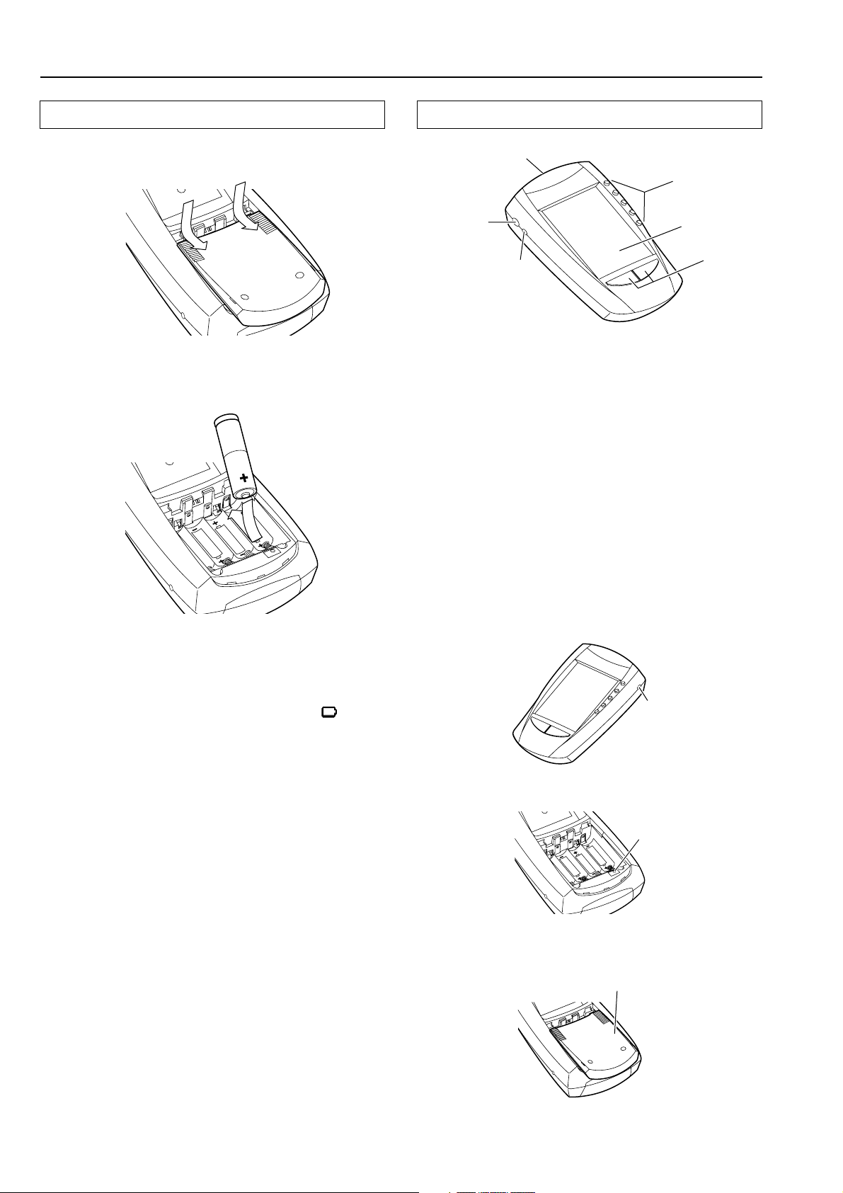
Insert batteries
1. Slide the battery cover off the back of the remote
controller.
2. Insert 4 AA batteries (included in package) as
indicated on the bottom of the battery compartment.
Characterizing the remote controller
Sending eye/Learning eye
Direct-access
buttons
Contrast dial
Backlight button
The intelligent remote controller can be used for all devices that
understand infrared remote controller signals. Its easy-to-use
touchscreen and its intuitive interface makes it a perfect remote
controller for every user.
The remote controller is completely customizable and
programmable. You can add devices and functions, relabel buttons,
record macros and set timers. To make the remote controller your
universal remote controller, it is designed to learn from existing
remote controllers.
Direct-access buttons
The buttons labeled MUTE, CH, and VOL are direct-access buttons.
The direct-access buttons make these frequently used functions
available even when the touchscreen is off. You can program them
so that they always operate the same components — for example, the
TV. Or, you can program them to operate different devices at
different times.
Touchscreen
Left/Right
buttons
3. Slide the battery cover back on.
After a few seconds, the remote controller starts up
automatically and beeps twice to indicate that it is ready to use.
When batteries are running low, the Low Battery icon
the center top of the display. Replace the batteries as soon as possible
to ensure perfect performance.
Note:
• The remote controller retains all settings when batteries have run
out or when you replace them. You will only have to reset the
clock.
• Do not mix new batteries with old batteries or different kinds of
batteries.
• To avoid corrosion, remove the batteries if the remote controller
is not to be used for a long time.
• Remove dead batteries immediately to avoid damage from
corrosion. If the remote controller does not operate smoothly,
replace both the batteries at the same time.
blinks at
Serial port
Reset button
Battery cover
8
Setting up the remote controller
Touch the screen to start
To turn on the screen, tap it gently with your finger.
To use the touchscreen, simply tap the images you see on the screen.
There’s no need to turn the screen off — it shuts off automatically to
save power.
Be sure to read the manual for important information about care and
use of the touchscreen.
Fresh out of the box, the remote controller is already set up to work
with popular components made by Integra/Onkyo.
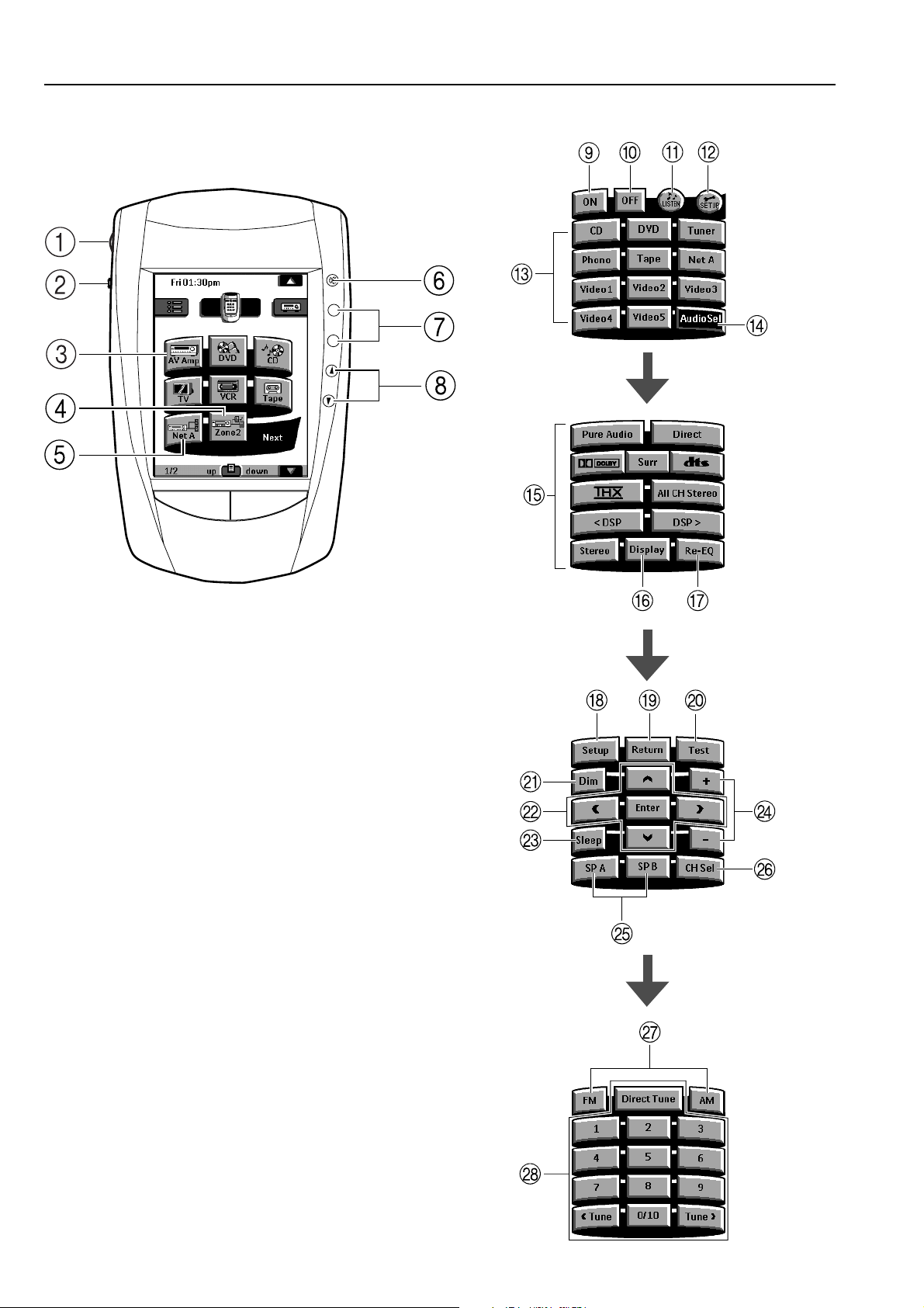
Home menu
1
–
CONT
+
2
LIGHT
3
MUTE
7
8
9
+
CH
–
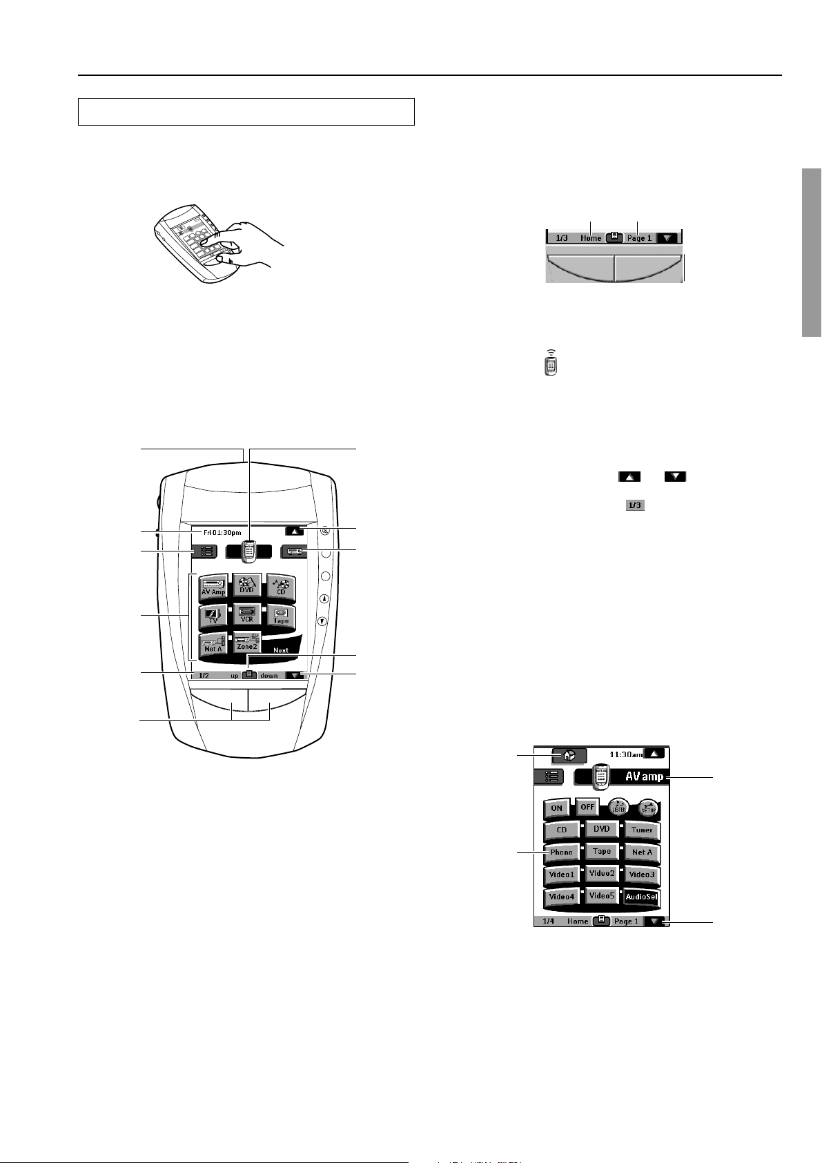
6. Left and Right buttons
The Left and Right buttons change function depending on the device
the remote controller is operating. The current function is displayed
on the touchscreen right above the button. The function can be either
an IR (infrared) command that is transmitted, or a jump to a specific
device page.
The Left button function The Right button function
7. Remote controller icon
When you send a command, the remote controller icon shows
transmitting signals
. The name of the active device is indicated on
the device tab.
Press and hold the icon for 3 seconds to go to the Setup menu of the
remote controller.
8. Scroll button
Most devices have more than one control panel. You can scroll
through these control panels using
and . The panel number
on the left bottom of the screen indicates the panel number and the
total number of panels, for example
.
By touching and holding a scroll button, you go repeatedly through
all the control panels of a device in a loop.
9. Switch between the Home menu and the Device menu
you selected prior to the Home menu.
4
5
6
VOL
10
11
1. Sending eye (IR transmitter)/Learning eye
Send commands to devices.
For learning commands from other remote controllers.
2. Current time and day
For setting the time and day, refer to “Adjust the Settings” (page 72).
3. Macro menu
Execute stored lists of commands.
4. Control panel
Tap buttons to select a components.
5. Panel number
Shows what panel you’re seeing.
10. Mode menu
Customize the remote controller.
11. Scroll button
Display next control panel.
Component’s control panel
When you select any component from the Home menu, the control
panel shown below appears.
1
3
2
4
1. Home
If you get lost, you can always go to the Home menu screen. Just
tap Home.
2. Tap name of component to display component’s
control panels.
3. You can also use the Device menu; tap to display it.
4. Tap to scroll to next panel for this component.
9
Index parts and facilities
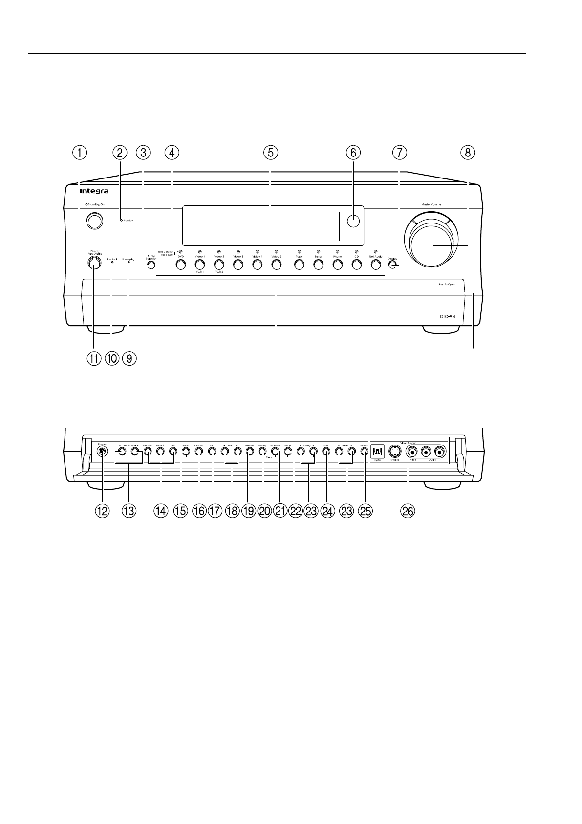
Here is an explanation of the controls and displays on the front panel of the DTC-9.4.
Front panels
Front door
Push here to open the front door.
L
10

Index parts and facilities
For further operational instructions, see the pages indicated in
brackets [ ].
Front panels
Standby/On button [30]
After plugging in the power cord, the DTC-9.4 turns on and the
display lights up, the DTC-9.4 turns on and the display lights up. If
pressed again, the DTC-9.4 returns to the standby state. In the
standby state, the display is turned off and the DTC-9.4 cannot be
operated.
Standby indicator [7, 30]
Lights when the DTC-9.4 is in the standby state and when a signal is
received from the remote controller.
Audio Selector button [35]
Press to select the type of audio input signal.
Input source buttons and indicators (DVD, Video
1–5, Tape, Tuner, Phono, CD, and Net Audio) [31,
36, 38, 40]
Press these buttons to select the input source for the main zone.
To select the input source for the remote zone (Zone 2) or recording
out (Rec Out), first press the Zone 2 or Rec Out button, and then
press the desired input source button. The input channel with its
indicator lit red is output to Rec Out and the one with its indicator lit
green is output to Zone 2.
Front display
Rec Out/Zone 2/Off buttons [38-40]
These buttons allow you to use the DTC-9.4 to output to a remote
zone (Zone 2) or to another component for recording (Rec Out).
Press the Rec Out button to output the audio and video signals to a
recording component for recording. Press the Zone 2 button to enjoy
the output from the DTC-9.4 in a different room, which is referred to
as the remote zone (Zone 2).
When either button is pressed, the currently selected input source for
recording or outputting to the remote zone is displayed in the front
panel display. If “SOURCE” is displayed, then the same input
source as that selected for the main zone will be output.
To select an input source, press the desired button (Rec Out or Zone
2) and then press one of the input source button within 8 seconds.
That source will be output for recording or viewing in the remote
zone.
To set the output to the source channel, press the desired button (Rec
Out or Zone 2) twice in succession. To disable the Rec Out output,
press the Rec Out button, and then press the Off button within 8
seconds after pressing the Rec Out button. To disable the Zone 2
output, press the Off button.
Note:
The Rec Out and Zone 2 buttons use the same circuit and therefore
cannot be used at the same time. When Rec Out is selected, nothing
is output to Zone 2. When Zone 2 is selected, Rec Out is
automatically fixed to Source.
Stereo button [32]
Selects for the stereo listening mode.
Surround button [32]
Selects for the Dolby Pro Logic II, DTS Neo:6, Dolby Digital, or
DTS listening modes.
Remote control sensor [7]
Display button [33]
Press to display information about the current input source signal.
Each time you press the Display button, the screen changes to show
you different information concerning the input signal.
Master Volume dial [31, 35]
Use to control the volume in the main zone. The volume for the
remote zone (Zone 2) is independent.
Upsampling indicator [65]
Lights during upsampling.
Pure Audio indicator [32]
Lights during pure audio playback.
Direct/Pure Audio button [32, 35]
Press to switch between the direct and pure audio listening modes.
Phones jack [31, 33]
This is a standard stereo jack for connecting stereo headphones.
Zone 2 Level / buttons [41]
Press to enter the mode for adjusting the volume in the remote zone
(Zone 2).
THX button [32]
Selects for the THX listening mode.
DSP / buttons [32]
Switches to the DSP (Digital Signal Processing) modes.
Dimmer button [34]
Press to set the brightness of the front display. There are four settings
available.
• The brightness of the front display can also be performed using
the remote controller.
Memory button [37]
Press to assign the radio station that you are currently tuned to a
preset channel or press to delete a previously preset station.
FM Mode button [36]
Press to change the stereo mode from Auto to Mono and vice versa.
Each time this button is pressed, the Auto indication turns on and off
indicating the current mode. If you are listening to an FM radio
station in stereo and the sound cuts out or there is a great deal of
noise, switch from Auto to Mono.
Setup button [51]
Press to enter the Setup Menu. The OSD Menu will appear on the TV
monitor as well as the front display on the DTC-9.4.
11
Index parts and facilities
Tuning / , Preset / buttons [36, 37, 51]
To tune into a radio station, press the Tuning / buttons. The tuner
frequency is displayed in the front display and it can be changed in
100-kHz increments for FM and 10-kHz increments for AM.
When FM is selected as the input source, you can hold down either
the Tuning
search feature. It will search for a station in the direction of the
button you pressed and stop when it tunes into one. When navigating
through the menu settings, these buttons move the cursor up or down
(or change the highlighted item).
To select a radio station that was stored using the Memory button,
press the Preset
When navigating through the menu settings, these buttons select the
value or item that you selected with the Tuning
When you press the Setup button, the Tuning and Preset buttons
become cursor buttons to be used for Setup Menu operations.
or button and then release it to activate the auto-
/ buttons.
/ buttons.
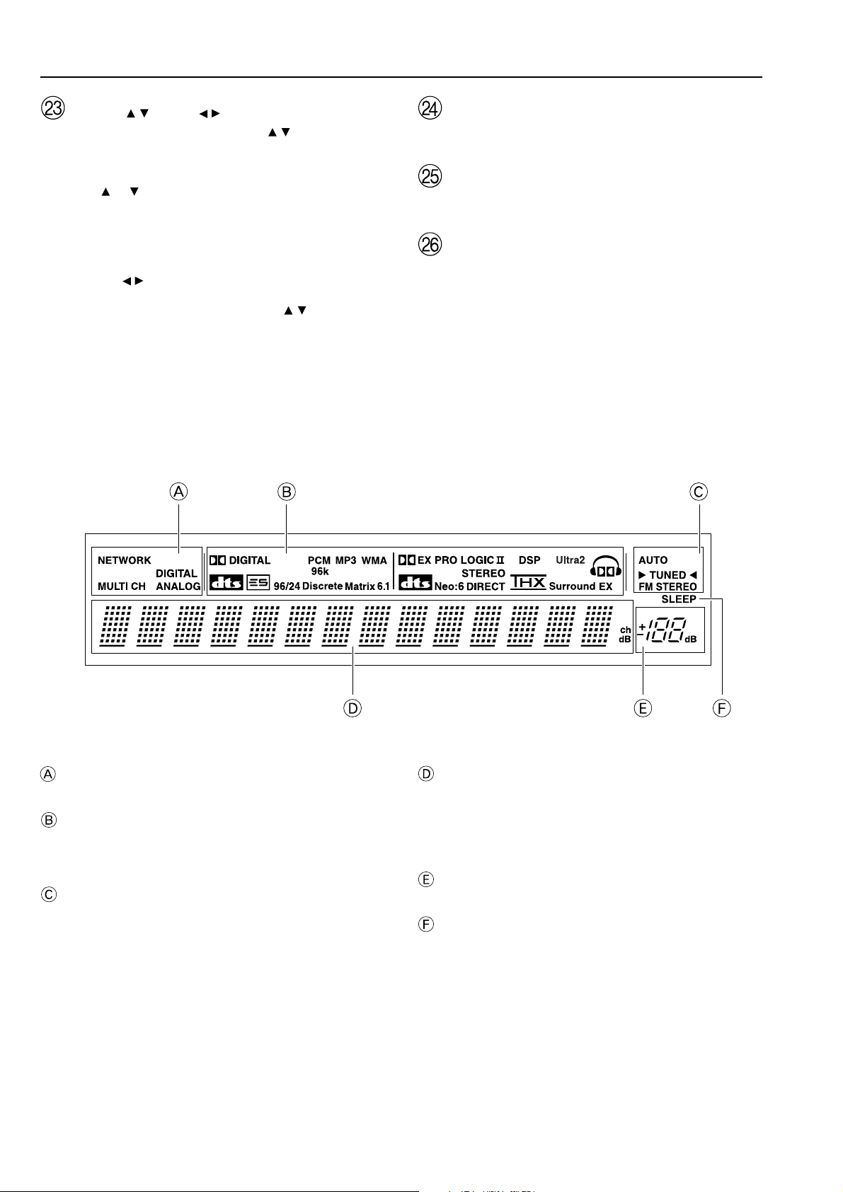
Front panel display
Enter button [51]
Press to display the screen for the item that is selected in the Setup
Menu.
Return button [51]
When in the Setup Menu, press to go back one level. If pressed while
at the Main Menu, you will exit the Setup Menu.
Video 5 Input terminals [21]
For connecting a video camera or game device.
Input signal path indicators
Shows from which terminal the input signal is coming.
Listening mode or digital input format indicators
Some of these indicators light to show the format of the current input
source. In addition, some of these listening mode indicators lights to
indicate the current listening mode.
Tuning indicators
AUTO indicator
Lights when receiving FM broadcasts in the stereo mode. Turns
off when placed into the monaural mode.
TUNED indicator
Lights when a radio station is received.
FM STEREO indicator
Lights when an FM broadcast station is received in stereo.
12
Multi function display
During normal operation, shows the current input source and
volume. When the FM or AM input is selected, shows the frequency
and preset number. When the Display button is pressed, shows the
listening mode and input source format. However, does not show the
source format when the FM or AM source is selected.
Volume display
Shows the volume level.
SLEEP indicator
Lights when the sleep timer is turned on.
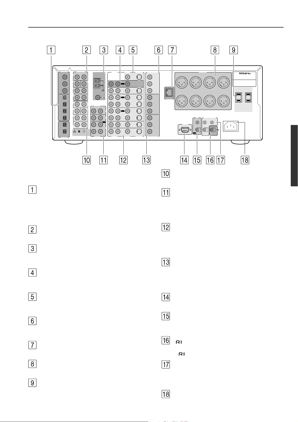
Index parts and facilities
Rear panel
COAX
OPT
OPT
DIGITAL
INPUT
1
2
3
1
2
3
4
1
2
DIGITAL
OUTPUT
FRONT
SUB
SURR
SURR
BACK/
ZONE 2
FRONT
SUB
SURR
SURR
BACK
PRE OUT
L
R
R
R
R
GND
L
L
CENTER
MULTI CH
INPUT
L
CENTER
ANTENNA
AUDIO
R
R
AUDIO
AM
FM
75
L
PHONO
CD
OUT
TAPE
IN
L
R
R
AUDIO
AUDIO
VIDEO
S VIDEO
MONITOR
OUT
L
ZONE 2
OUT
DVD
IN
OUT
VIDEO 1
IN
OUT
VIDEO 2
IN
VIDEO 3
IN
VIDEO 4
IN
L
VIDEO
S VIDEO
For more information regarding connection procedures, see pages
indicated in brackets [ ].
DIGITAL INPUT/OUTPUT [17-21]
These jacks are for connecting components with digital input and
output capabilities. To connect a CD player, see page 17; to connect an
MD or CD recorder, see page 17; to connect a DAT deck, see page 17;
to connect a DVD player, see page 18; to connect a DVD recorder, see
page 20; and to connect a digital satellite tuner, see page 21.
COMPONENT
VIDEO
OUTPUT
Y
B
P
P
R
INPUT 1
Y
B
P
P
R
INPUT 2
Y
P
B
P
R
COMPONENT
VIDEO
ETHERNET
(
NET-TUNE
SURR BACK / ZONE 2
)
RIGHT
RS232
SURR BACK / ZONE 2
LEFT
I R
IN
OUT
PRE OUT
SURROUND
RIGHT
12
V TRIGGER OUT
A
ZONE 2
B
CONTROL
LINK OUT
REMOTE
CONTROL
LEFTRIGHTCENTERSUBWOOFER
SURROUND
LEFT
AC INLET
AV CONTROLLER
MODEL NO.
DTC
AC OUTLETS
AC 120 V 60 Hz
SWITCHED
TOTAL 120W 1A MAX.
-
9.4
MULTI CH INPUT [28]
This connector is for connecting components with a multi-channel output.
PHONO/CD/TAPE AUDIO IN/OUT [17]
These connectors are for connecting to the audio input and output
jacks on audio components. To connect a turntable, see page 17; to
connect a CD player, see page 17; and to connect a cassette tape
deck, MD recorder, or CD recorder, see page 17.
PRE OUT (RCA type) [28]
Connect a power amplifier to this jack.
ANTENNA [23, 24]
These jacks are for connecting the FM indoor antenna and AM loop
antenna that are supplied with the DTC-9.4.
ZONE2 AUDIO/VIDEO OUT [25]
These jacks are for connecting the components that will be used in
the remote zone (Zone 2).
MONITOR OUT VIDEO/S VIDEO [19]
These jacks are for connecting to the video input jacks on television
monitors or projectors.
COMPONENT VIDEO OUTPUT [19]
These jacks are for connecting to the component video input jacks on
television monitors or projectors.
ETHERNET (NET-TUNE) [43]
This connector is for connecting to an Ethernet network.
PRE OUT (XLR type) [29]
Connect a power amplifier to this jack.
AC OUTLETS [27]
This AC outlet is provided to plug in the power cord from another
component.
DVD/VIDEO1-4 IN/OUT [18-21]
These connectors are for connecting to the video input and output
jacks on video components. To connect a DVD player, see page 18;
to connect a DVD recorder, see page 20; to connect a VCR, see page
19; and to connect a Satellite tuner, see page 21.
COMPONENT VIDEO INPUT1/2 [18-20]
These connectors are for connecting to the component video outputs
of video components that have them. To connect a DVD player, see
page 18; to connect a DVD recorder, see page 20; and to connect a
Satellite tuner, see page 21.
RS232 [27]
This connector is for connecting to the RS-232 port of an external device.
IR IN/OUT [26]
These connectors are for connecting the remote sensor of a multiroom kit (sold separately).
[27]
This jack is for connecting other Onkyo components equipped with
the same terminal.
12V TRIGGER OUT ZONE 2/A/B (CONTROL LINK
OUT) [28]
These connectors are used to connect to the 12V TRIGGER IN
terminal of a component if one has one.
AC INLETS [7]
This connector is for connecting the supplied power cord.
13
Index parts and facilities
Remote controller
Home menu
–
CONT
+
LIGHT
AV Amp (Select AV Amp on the Home menu)
(page 1/4)
MUTE
+
CH
–
VOL
(page 2/4)
(page 3/4)
(page 4/4)
14
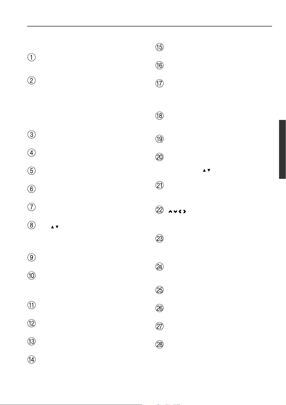
Index parts and facilities
For details on how to use the remote controller, refer to “Using
the remote controller” (page 72).
Select AV Amp in the Home menu to display the operation buttons.
CONT +/– buttons
If the display stays blank or becomes black, adjust the contrast dial
on the left side.
LIGHT button
Press to turn on the backlight for brighter display when you use the
DTC-9.4 in the dark room.
The backlight shuts off automatically after a few seconds to save
power.
Note:
You can choose to activate the backlight automatically when you
activate the remote controller. (For details about the settings, see
“Second setup panel” under “Adjust the Settings” on page 72.)
AV Amp button
Before operating the DTC-9.4, press this button.
Zone 2 button [41]
Press to perform operations on the remote zone.
Net A button
Press to listen to the Net Audio.
MUTE button [34]
Press to activate the mute function.
Second operation menu (page 2/4)
Listening mode buttons [32]
You can select a listening mode.
Display button [33]
For changing the display in the front display.
Re-EQ button [65, 68]
Depending on the listening mode, you can turn the Re-EQ function
on or off.
Third operation menu (page 3/4)
Setup button [51]
Press to display the Setup Menu on the TV screen and in the display.
Press again to exit the menu.
Return button [51]
Press to enter the selected setting and return to the previous menu.
Test button [55]
This button is used to set the speaker output levels. Use this button in
conjunction with the Level
speakers levels without entering the Setup Menu.
Dim button [34]
Adjusts the display brightness.
There are three settings available: normal, dark and very dark.
/ and CH Sel buttons to calibrate the
CH +/– button [37, 41]
When AV Amp is selected, for selecting a tuner preset channel.
VOL / buttons [31, 35, 41]
When AV Amp is selected, for adjusting the volume. When Zone 2
is selected, for adjusting the volume in the Zone 2.
First operation menu (page 1/4)
ON button [30, 41]
Press to turn on the DTC-9.4.
OFF button [30]
Press to place the DTC-9.4 in the standby state.
Be aware that pressing the Standby button only places the DTC-9.4
in standby and does not turn the power completely off.
LISTEN button [32]
For displaying the 2/4 listening mode page.
SETUP button
For displaying the 3/4 setup operation page.
Input Selector buttons [31, 36, 41]
Select an input source for the main zone.
Audio Sel button [35]
Press to select the audio input signal.
/ / / , Enter buttons [51]
When in the Setup Menu, press the upper and lower arrow buttons to
select an item, press the right and left arrow buttons to select parameter
values or modes, and press the Enter button to advance to the next item.
Sleep button [34]
Press to set the sleep function.
The Sleep button enables you to set the DTC-9.4 to turn off
automatically after a specified time period.
+/– buttons [34, 55]
Select the speaker whose volume is to be adjusted using the CH Sel
button and adjust the volume using the +/– buttons.
SP A/B buttons
These buttons are not used with the DTC-9.4.
CH Sel button [34]
Press to select a speaker channel when adjusting the speaker level.
FM/AM buttons [36]
Select the tuner band.
Not used with the DTC-9.4.
The buttons can be used to do direct tuning or tune in a radio station
on some Onkyo products.
15
Connecting to Audio/Video equipment
PR
PB
Y
PR
PB
Y
• Be sure to always refer to the instructions that came with the
component that you are connecting.
• Do not plug in the power cord until all connections have been
properly made.
• For input jacks, red connectors (marked R) are used for the
right channel, white connectors (marked L) are used for the
left channel, and yellow connectors (marked VIDEO) are
used for video connection.
• Insert all plugs and connectors securely. Improper
connections can result in noise, poor performance, or
damage to the equipment.
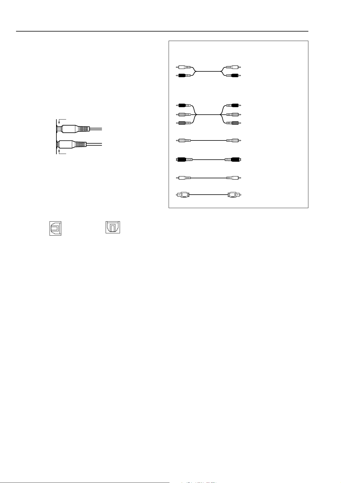
Improper connection
Inserted completely
• Do not bind audio/video connection cables with power cords
and speaker cables. Doing so may adversely affect the
picture and sound quality.
• The optical digital jacks are all of the shutter-type
construction. Connect an optical cable by first making sure
the cable is oriented correctly and then inserting it into the
jack pushing the shutter lid inwards.
Cables are depicted in the connection diagrams as shown below.
Left (white)
Right (red)
L
Audio connection cable
R
Component video
connection cable
Video connection cable
S video connection cable
Coaxial cable
Optical cable
Rear optical jack Front optical jack
16
Connecting to Audio/Video equipment
Here is an explanation of typical ways to connect various components to the DTC-9.4. There are many ways that any one component can be
connected, and it is up to you to decide which method best fits your situation. The directions given here are only one option and should only be
thought of as such. It is best to fully understand the nature of each connector and terminal as well as those of your components and their features
to ascertain which method of connection is best.
: Signal flow
Digital audio output (optical)
DIGITAL
INPUT
COAX
Digital audio input (optical)
3. Cassette tape deck, MD
recorder, DAT deck, or CD
recorder (TAPE)
Analog audio input
Analog audio output
R (red)
L (white)
R (red)
L (white)
1
2
3
OPT
1
2
3
4
OPT
1
2
DIGITAL
OUTPUT
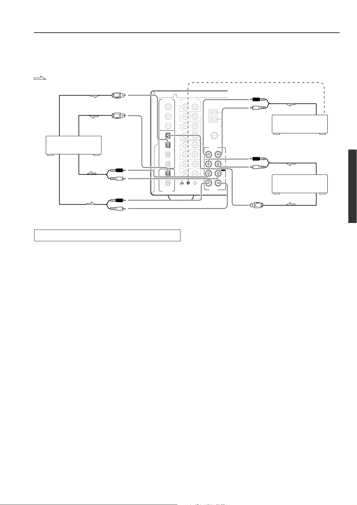
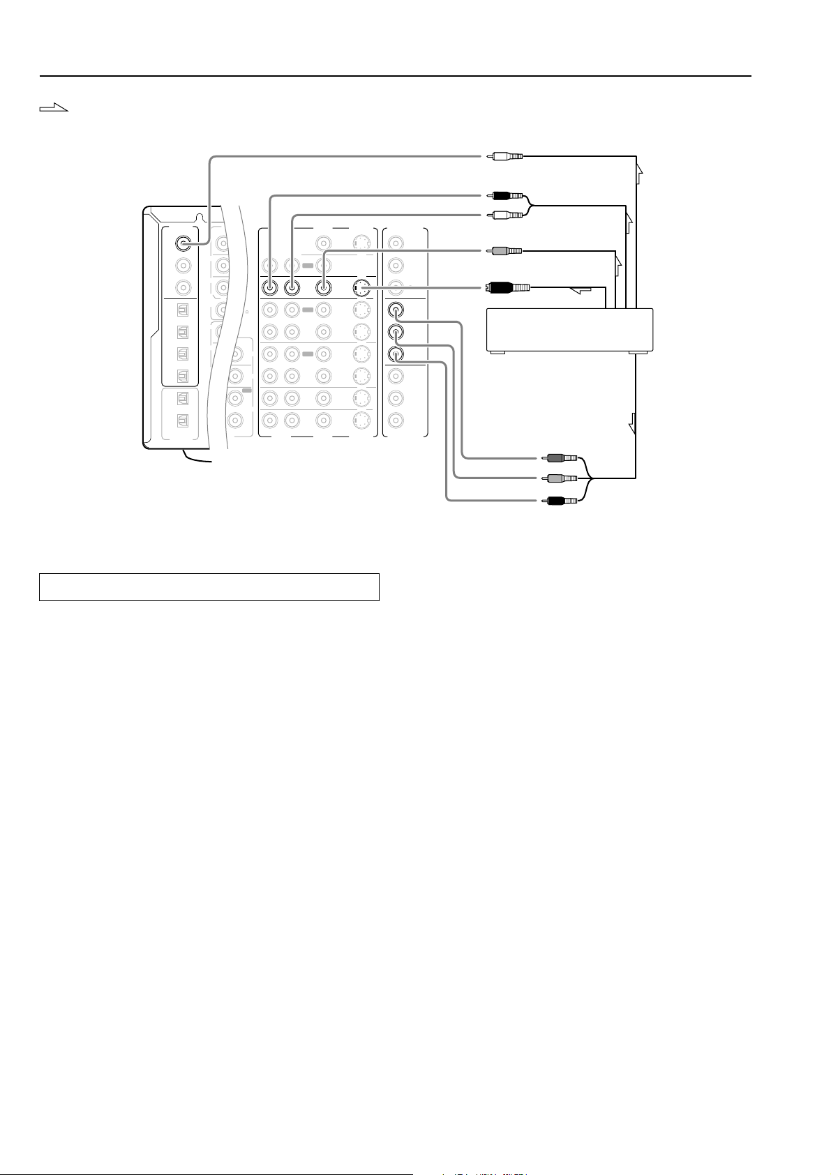
Connecting your audio components
Below is an example of how you can connect your audio components
to the DTC-9.4. Refer to the diagram above for the following
connection examples.
AUDIO IN/OUT
These are the analog audio inputs and outputs. There are eight audio
inputs and three audio outputs on the rear panel. The audio inputs
and outputs require RCA-type connectors.
DIGITAL INPUT/OUTPUT
On the rear panel of the DTC-9.4, there are three coaxial digital
inputs, four optical digital inputs, and two optical digital output. To
the digital inputs, connect CD players, LD players, DVD players, or
other digital source component. To the digital output, connect MD
recorders, CD recorders, DAT decks, or other similar components.
• Since an analog connection must be made when using Rec Out
or Zone 2, make sure that the connection to the input source is
not digital only, but analog as well.
• When using an optical input or output jack, always use an optical
fiber cable.
1. Connecting a compact disc player (CD)
Using an RCA audio cable, connect the output jacks of the compact
disc player to the CD AUDIO jacks of the DTC-9.4. Make sure that
you properly connect the left channel to the L jack and the right
channel to the R jack.
If the compact disc player has a digital output, connect it to either the
DIGITAL INPUT COAX jack or DIGITAL INPUT OPT jack of the
DTC-9.4 depending on the type of connector on the compact disc
player.
With the initial settings of the DTC-9.4, the CD input source is
set for digital input at the OPT 1 jack.
If the digital connection is made to a different jack, this must be
changed at Setup Menu → Input Setup → Digital Setup (see page
57).
Ground wire (earth)
R (red)
L (white)
R (red)
L (white)
Analog audio output
Analog audio output
Digital audio output (optical)
2. Turntable (PH)
1. CD player (CD)
FRONT
SUB
SURR
SURR
BACK/
ZONE 2
FRONT
SUB
SURR
SURR
BACK
GND
R
PRE OUT
R
R
R
L
L
L
CENTER
MULTI CH
INPUT
L
CENTER
ANTENNA
AUDIO
R
R
AUDIO
AM
FM
75
L
PHONO
CD
OUT
TAPE
IN
L
2. Connecting a turntable (PHONO)
Using an RCA audio cable, connect the output jacks of the turntable
to the PHONO audio jacks of the DTC-9.4. Make sure that you
properly connect the left channel to the L jack and the right channel
to the R jack.
Note:
The DTC-9.4 is designed for use with moving magnet cartridges. For
proper operation, connect a ground (or earth) wire to the GND
terminal. For some turntables, however, connecting the ground wire
may cause increased noise, and in such a case, a ground wire is not
necessary and should not be connected.
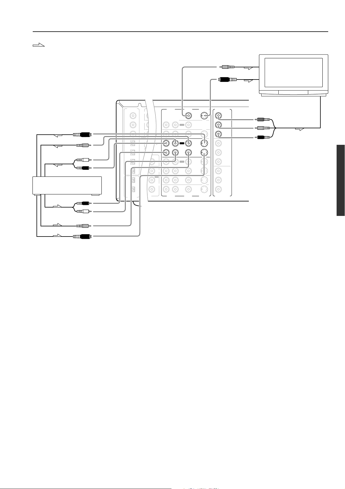
3. Connecting a cassette tape deck, MD recorder, DAT deck, or
CD recorder (TAPE)
Using RCA audio cables, connect the output jacks (PLAY) of the
device to the TAPE AUDIO IN jacks of the DTC-9.4 and connect
the input jacks (REC) of the device to the TAPE AUDIO OUT jacks
of the DTC-9.4. Make sure that you properly connect the left
channels to the L jacks and the right channels to the R jacks.
If the device has a digital output, connect it to either the DIGITAL
INPUT COAX jack or DIGITAL INPUT OPT jack of the DTC-9.4
depending on the type of connector on the device.
With the initial settings of the DTC-9.4, the TAPE input source
is set for digital input at the OPT 2 jack.
If the digital connection is made to a different jack, this must be
changed at Setup Menu → Input Setup → Digital Setup (see page
57).
If the device has a digital input, connect it to the DIGITAL OUTPUT
OPT 1 or 2 jack of the DTC-9.4 for digital recording of the REC
OUT signal from the DTC-9.4.
Note:
The output from the DIGITAL OUTPUT jack of the DTC-9.4 is
only the digital signal input to the DIGITAL INPUT jack.
17
Connecting to Audio/Video equipment
PR
FRONT
SUB
SURR
R
GND
SURR
BACK/
ZONE 2
R
FRONT
SUB
SURR
SURR
BACK
R
R
DIGITAL
INPUT
DIGITAL
OUTPUT
OPT
OPT
2
1
2
3
4
1
2
1
3
COAX
AUDIO
VIDEO
S VIDEO
MONITOR
OUT
IN
IN
IN
IN
IN
ZONE 2
DVD
VIDEO 1
VIDEO 2
VIDEO 3
VIDEO 4
AUDIO
VIDEO
S VIDEO
COMPONENT
VIDEO
Y
P
B
P
R
OUTPUT
INPUT 1
Y
P
B
P
R
INPUT 2
Y
P
B
P
R
R
L
OUT
OUT
OUT
PHONO
L
CD
TAPE
L
IN
OUT
FM
75
R
L
COMPONENT
VIDEO
AM
: Signal flow
Digital audio output (coaxial)
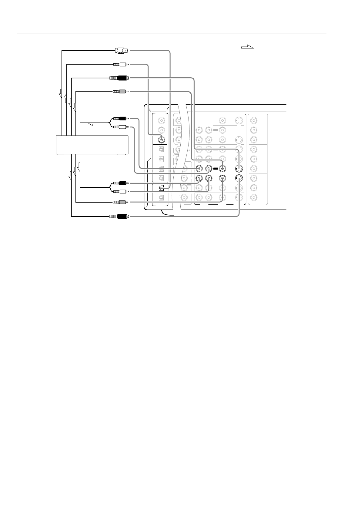
Connecting your video components
Below is an example of how you can connect your video components
to the DTC-9.4. Refer to the diagram above for the following
connection examples.
COMPONENT VIDEO INPUT/OUTPUT
For DVD players or other devices that have component video
connectors, the DTC-9.4 has two banks of component video input
connectors (Y, P
9.4 also has one bank of component video output connectors for
direct component video output to the matrix decoder of a television,
projector, or other display device. By sending the pure component
video signal directly, the signal forgoes the extra processing that
normally would degrade the image. The result is vastly increased
image quality, with incredibly lifelike colors and crisp detail.
VIDEO IN/OUT
These are the video inputs and outputs. On the rear panel, there are
five video inputs and two video outputs and each one includes both
composite video and S video configurations.
Connect VCRs, VTRs, LD players, DVD players, and other video
components to the video inputs. Connect VCRs, VTRs, and other
recording components to the video outputs to make video
recordings.
• When connecting a VCR or other video component, make sure
you connect its audio and video leads to the same bank (e.g.,
both to VIDEO 3).
• The VIDEO 5 inputs are located on the front panel.
The flow of the video signals is as follows:
Signals that comes in from VIDEO and S VIDEO INPUT are output to
VIDEO, S VIDEO and COMPONENT VIDEO. However, signals
that comes in from COMPONENT VIDEO INPUT are only output to
COMPONENT VIDEO OUTPUT. When connecting a video player
to the COMPONENT VIDEO INPUT jacks, be sure to connect your
television to the COMPONENT VIDEO OUTPUT jacks.
18
B, PR) for direct component video input. The DTC-
R (red)
Analog audio output
L (white)
Video output
S Video output
4. DVD player (DVD)
Y
P
B
P
R
Component video output
4. Connecting a DVD player (DVD)
Using an RCA video cable, connect the video output jack
(composite) of the DVD or LD player to the DVD VIDEO IN jack of
the DTC-9.4. Or if the DVD or LD player has an S video output jack,
connect it to the DVD S VIDEO IN jack with an S video cable. Or if
the device has component video outputs, connect them to one of the
banks of COMPONENT VIDEO INPUT jacks on the DTC-9.4.
The default setting for DVD video input is set to “INPUT 1”
(COMPONENT VIDEO INPUT 1).
If you connect the DVD player to video jacks other than the
COMPONENT VIDEO INPUT 1 jacks, change the setting for
“b.Component Video” at the “2-3.Video Setup sub-menu” to
appropriate value (see page 59).
Using an RCA audio connection cable, connect the audio output
jacks of the DVD or LD player to the DVD AUDIO IN jacks of the
DTC-9.4. Make sure that you properly connect the left channel to the
L jack and the right channel to the R jack.
If the device has a digital output, connect it to either the DIGITAL
INPUT COAX jack or DIGITAL INPUT OPT jack of the DTC-9.4
depending on the type of connector on the DVD player.
With the initial settings of the DTC-9.4, the DVD input source is
set for digital input at the COAX 1 jack.
If the digital connection is made at a different jack, this must be
changed at Setup Menu → Input Setup → Digital Setup (see page 57).
P
FRONT
SUB
SURR
R
GND
SURR
BACK/
ZONE 2
R
FRONT
SUB
SURR
SURR
BACK
R
R
DIGITAL
INPUT
DIGITAL
OUTPUT
OPT
OPT
2
1
2
3
4
1
2
1
3
COAX
AUDIO
VIDEO
S VIDEO
MONITOR
OUT
IN
IN
IN
IN
IN
ZONE 2
DVD
VIDEO 1
VIDEO 2
VIDEO 3
VIDEO 4
AUDIO
VIDEO
S VIDEO
COMPONENT
VIDEO
Y
P
B
P
R
OUTPUT
INPUT 1
Y
P
B
P
R
INPUT 2
Y
P
B
P
R
R
L
OUT
OUT
OUT
PHONO
UDIO
L
CD
TAPE
L
UDIO
IN
OUT
AM
FM
75
R
L
COMPONENT
VIDEO
Connecting to Audio/Video equipment
: Signal flow
S Video input
Video input
Video input
5. TV monitor or projector
(MONITOR OUT)S Video input
Y
P
B
P
R
Component video input
Analog audio
input
L (white)
R (red)
6. VCR (VIDEO 1)
R (red)
Analog audio
output
L (white)
Video output
S Video output
5. Connecting a television monitor or projector (MONITOR
OUT)
The DTC-9.4 is equipped with a simple Y/C separate circuit and
simple Y/C mixed circuit. Since both the signal from the S VIDEO
and VIDEO inputs are output to the MONITOR OUT S VIDEO
output, if the television or projector is equipped with an S video
input, it is unnecessary to connect the video connectors. If it is
equipped with only a video input, connect it to the MONITOR OUT
VIDEO output.
6. Connecting a video cassette recorder (VIDEO 1)
Using RCA video cables, connect the video output jack (composite)
of the video cassette recorder to the VIDEO 1 VIDEO IN jack of the
DTC-9.4 and connect the video input jack of the video cassette
recorder to the VIDEO 1 VIDEO OUT jack of the DTC-9.4. Or if the
video cassette recorder has S video input and output jacks, connect
them to the VIDEO 1 S VIDEO IN and OUT jacks of the DTC-9.4
using S video cables. Or if the video cassette recorder has component
video outputs, connect them to one of the banks of COMPONENT
VIDEO INPUT jacks on the DTC-9.4.
Using an RCA video cable, connect the video input jack (composite)
of the device to the MONITOR OUT VIDEO jack of the DTC-9.4.
Or if the device has an S video input jack, connect it to the
MONITOR OUT S VIDEO jack of the DTC-9.4 using an S video
cable. Or if the device has component video inputs, connect them to
the bank of COMPONENT VIDEO OUTPUT jacks on the DTC-9.4.
Note that the OSD Menu data will be output to the MONITOR OUT
VIDEO, S VIDEO and COMPONENT VIDEO jacks. When you
connect any OSD-specific monitor TV to the VIDEO connectors,
you can disable the OSD output to COMPONENT VIDEO
OUTPUT. To disable the OSD output, select Setup Menu →
Preference → OSD Setup → Component Video, and then select
“Not Activated” (See page 71).
The default setting for the VIDEO 1 video input is set to “INPUT
2” (COMPONENT VIDEO INPUT 2).
If you connect the video deck to video jacks other than the
COMPONENT VIDEO INPUT 2 jacks, change the setting for
“b.Component Video” at the “2-3.Video Setup sub-menu” to
appropriate value (see page 59).
Using RCA audio cable, connect the audio output jacks of the video
cassette recorder to the VIDEO 1 AUDIO IN jacks of the DTC-9.4
and connect the audio input jacks of the video cassette recorder to the
VIDEO 1 AUDIO OUT jacks of the DTC-9.4. Make sure that you
properly connect the left channels to the L jacks and the right
channels to the R jacks.
If you are connecting a digital output device to the VIDEO 1 jack
instead of a VCR, connect it to either the DIGITAL INPUT COAX
jack or DIGITAL INPUT OPT jack depending on the type of
connector on the device.
With the initial settings of the DTC-9.4, the VIDEO 1 input
source is set for digital input at the COAX 2 jack.
If the digital connection is made at a different jack, this must be
changed at Setup Menu → Input Setup → Digital Setup (see page
57).
19
Connecting to Audio/Video equipment
PRE
FRONT
SUB
SURR
R
GND
SURR
BACK/
ZONE 2
R
FRONT
SUB
SURR
SURR
BACK
R
R
DIGITAL
INPUT
DIGITAL
OUTPUT
OPT
OPT
2
1
2
3
4
1
2
1
3
COAX
AUDIO
VIDEO
S VIDEO
MONITOR
OUT
IN
IN
IN
IN
IN
ZONE 2
DVD
VIDEO 1
VIDEO 2
VIDEO 3
VIDEO 4
AUDIO
VIDEO
S VIDEO
COMPONENT
VIDEO
Y
P
B
P
R
OUTPUT
INPUT 1
Y
P
B
P
R
INPUT 2
Y
P
B
P
R
R
L
OUT
OUT
OUT
PHONO
L
CD
TAPE
L
IN
OUT
AM
FM
75
R
L
COMPONENT
VIDEO
Digital audio input (optical)
Digital audio output (coaxial)
S Video input
Video input
Analog audio
input
R (red)
L (white)
7. DVD recorder, other digital video
recording device (VIDEO 2)
R (red)
Analog audio
output
L (white)
Video output
S Video output
: Signal flow
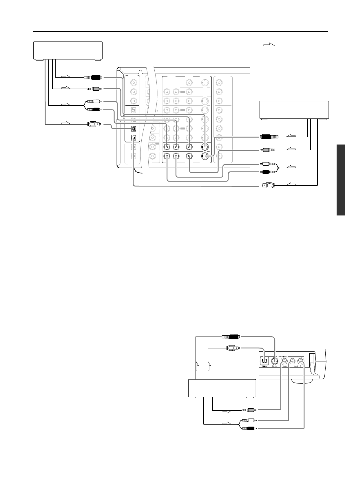
7. Connecting a DVD recorder or other digital video recording
device (VIDEO 2)
Using RCA video cables, connect the video output jack (composite)
of the device to the VIDEO 2 VIDEO IN jack of the DTC-9.4 and
connect the video input jack of the device to the VIDEO 2 VIDEO
OUT jack of the DTC-9.4. Or if the device has S video input and
output jacks, connect them to the VIDEO 2 S VIDEO IN and OUT
jacks of the DTC-9.4 using S video cables. Or if the device has
component video outputs, connect them to one of the banks of
COMPONENT VIDEO INPUT jacks on the DTC-9.4.
The default setting for the VIDEO 2 video input is set to
“VIDEO” (VIDEO IN or S VIDEO IN).
If you connect the device to video jacks other than the VIDEO IN or
S VIDEO IN jacks, change the setting for “b.Component Video” at
the “2-3.Video Setup sub-menu” to appropriate value (see page 59).
Using RCA audio cables, connect the audio output jacks of the
device to the VIDEO 2 AUDIO IN jacks of the DTC-9.4 and connect
the audio input jacks of the device to the VIDEO 2 AUDIO OUT
jacks of the DTC-9.4. Make sure that you properly connect the left
channels to the L jacks and the right channels to the R jacks.
If the device has a digital output, connect it to either the DIGITAL
INPUT COAX jack or DIGITAL INPUT OPT jack of the DTC-9.4
depending on the type of connector on the device.
With the initial settings of the DTC-9.4, the VIDEO 2 input
source is set for digital input at the COAX 3 jack.
If the digital connection is made at a different jack, this must be
changed at Setup Menu → Input Setup → Digital Setup (see page
57).
If the device has a digital input, connect it to the DIGITAL OUTPUT
OPT jack of the DTC-9.4 for digital recording of the REC OUT
signal from the DTC-9.4.
Note:
The output from the DIGITAL OUTPUT jack of the DTC-9.4 is
only the digital signal input to the DIGITAL INPUT jack.
20
Connecting to Audio/Video equipment
P
FRONT
SUB
SURR
R
GND
SURR
BACK/
ZONE 2
R
FRONT
SUB
SURR
SURR
BACK
R
R
DIGITAL
INPUT
DIGITAL
OUTPUT
OPT
OPT
2
1
2
3
4
1
2
1
3
COAX
AUDIO
VIDEO
S VIDEO
MONITOR
OUT
IN
IN
IN
IN
IN
ZONE 2
DVD
VIDEO 1
VIDEO 2
VIDEO 3
VIDEO 4
AUDIO
VIDEO
S VIDEO
COMPONENT
VIDEO
Y
P
B
P
R
OUTPUT
INPUT 1
Y
P
B
P
R
INPUT 2
Y
P
B
P
R
R
L
OUT
OUT
OUT
PHONO
L
CD
TAPE
L
IN
OUT
AM
FM
75
R
L
COMPONENT
VIDEO
8. Settop box, video camera
(VIDEO 3)
S Video output
Video output
Analog audio
output
Digital audio output (optical)
L (white)
R (red)
: Signal flow
9. Satellite tuner or television
(VIDEO 4)
S Video output
L (white)
R (red)
Video output
Analog audio
output
Digital audio output
(optical)
8, 9. Connecting a satellite tuner, television, or settop box
(VIDEO 3 or 4)
Using an RCA video cable, connect the video output jack
(composite) of the device to the VIDEO 3 (or 4) VIDEO IN jack of
the DTC-9.4. Or if the device has an S video output jack, connect it
to the VIDEO 3 (or 4) S VIDEO IN jack of the DTC-9.4 using an S
video cable. Or if the device has component video outputs, connect
them to one of the banks of COMPONENT VIDEO INPUT jacks on
the DTC-9.4.
The default setting for the VIDEO 3 and VIDEO 4 video inputs
are set to “VIDEO” (VIDEO IN or S VIDEO IN).
If you connect the device to video jacks other than the VIDEO IN or
S VIDEO IN jacks, change the setting for “b.Component Video” at
the “2-3.Video Setup sub-menu” to appropriate value (see page 59).
10. Connecting video camera, etc. (VIDEO 5 INPUT)
Using an RCA video cable, connect the video output jack
(composite) of the device to the VIDEO 5 VIDEO jack of the DTC-
9.4. Or if the device has an S video output jack, connect it to the
VIDEO 5 S VIDEO jack of the DTC-9.4 using an S video cable.
Using an RCA audio cable, connect the audio output jack of the
device to the VIDEO 5 AUDIO jacks of the DTC-9.4. Make sure that
you properly connect the left channel to the L jack and the right
channel to the R jack.
If the device has an optical digital output, connect it to the VIDEO 5
DIGITAL jack of the DTC-9.4.
The VIDEO 5 digital input is fixed to the OPTICAL input on the
front panel.
Using an RCA audio cable, connect the audio output jack of the
device to the VIDEO 3 (or 4) AUDIO IN jacks of the DTC-9.4.
Make sure that you properly connect the left channel to the L jack
S Video output
Front panel
and the right channel to the R jack.
If the device has a digital output, connect it to either the DIGITAL
INPUT COAX jack or DIGITAL INPUT OPT jack of the DTC-9.4
depending on the type of connector on the device.
With the initial settings of the DTC-9.4, the VIDEO 3 input source is
Digital output
(optical)
L
set for digital input at the OPT 3 jack, and the VIDEO 4 input
source is set for digital input at the OPT 4 jack.
If the digital connection is made at a different jack, this must be
changed at Setup Menu → Input Setup → Digital Setup (see page
57).
10. Video camera/ Video game
(VIDEO 5 INPUT)
Video output
Analog output
L
R
21
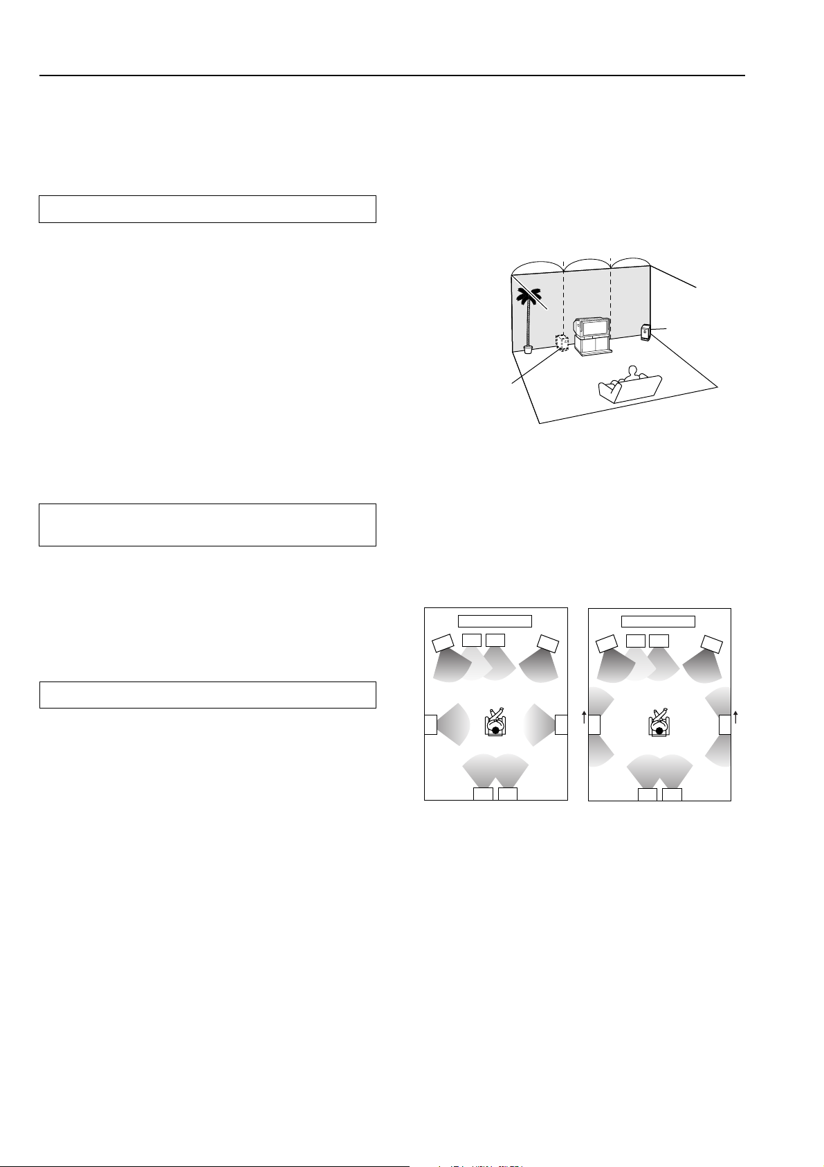
Speaker configuration and placement
Be aware that for surround playback, the configuration and
placement of your speakers are both very important.
For THX surround EX playback, we recommend that you use a
THX speaker system that is certified by THX Ltd.
Ideal speaker configuration
• Front right and left speakers
• Center speaker
Produces a rich sound image by serving as a sound source for
the front right and left speakers and enhancing the sonic
movement.
• Surround right and left speakers
Adds three-dimensional sonic movement and produces
environmental sound associated with the background and effect
sound for each scene.
• Surround back right and left speakers
Required for enjoying Dolby Digital EX, THX Surround EX,
DTS-ES Matrix 6.1, or DTS-ES Discrete 6.1 audio.
• Subwoofer
Produces powerful and heavy bass.
Minimum speaker configuration for surround
sound playback
• Place these speakers so that their height is 3 feet (1 meter) higher
than that of the listener’s ears.
Subwoofer
When bass sound is reproduced, its volume and quality greatly
depend on subwoofer placement. Those characteristics also depends
on the shape of your listening room as well as your listening point.
Generally speaking, good bass sound is obtained when the
subwoofer is placed in the corner of the room or at one-third the
length of the room.
Corner
1/3 room length
For optimizing the subwoofer placement, we recommend you to:
• Play a movie or music source containing good quality base sound,
• Take some experimenting while changing subwoofer’s position
in the room, and
• Try different positioning until you get the most out of the base
sound while fixing the listening point.
• Front right and left speakers
• Surround right and left speakers
The sound recorded for the center speaker and the subwoofer will be
properly distributed to the front right and left speakers for optimized
surround playback.
Speaker placement
Ideal speaker placement varies depending on the size of your room
and the wall coverings. Here, only typical example of speaker
placement and recommendations are shown.
In order to create the optimum conditions for the best sound quality,
be sure to place all the speakers so that the greatest difference
between the distances of each speaker to the listening position is
less than 20 feet (6 meters).
Important points regarding speaker placement
Front left and right speakers and center speaker
• Place these three speakers all at the same height.
• Place each speaker so that it is aimed at the location of the
listener’s ears when at the listening position.
• Place the right and left loudspeakers at an equal distance either
side of the listening point.
Layout with speakers
1
34
2
6
10
89
1 TV or screen
2 Front left speaker
3 Subwoofer
4 Center speaker
5 Front right speaker
5
Layout with dipolar
speakers
1
34
2
67
7
10
89
6 Surround left speaker
7 Surround right speaker
8 Surround back left speaker
9 Surround back right speaker
10 Listening position
5
Most dipoles have an arrow on them to indicate their orientation in
which that should be placed. For the correct acoustical phasing in the
room, dipolar surround speakers should be placed so that their
arrows point forward toward the screen.
Surround left and right speakers
• Place these speakers so that their height is 3 feet (1 meter)
higher than that of the listener’s ears.
Surround back left and right speakers
• For maximum effect of the new THX Ultra2 feature, place these
two speakers as close together as possible. Dipolar speakers,
however, should be placed apart the required amount.
22
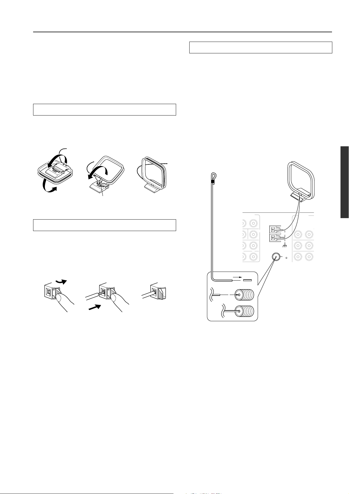
Connecting antennas
To use the tuner of DTC-9.4, it is necessary to prepare the supplied
FM and AM antennas.
• Adjustment and placement of the FM and AM antennas for
better reception must be done while listening to a station
broadcast.
• If better reception cannot be obtained, then placement of an
outside antenna is recommended.
Assembling the AM loop antenna
Assemble the loop antenna as shown in the illustration.
• Refer to “Connecting the AM loop antenna” below for details on
how to connect the loop antenna.
Insert into the hole.
Connecting the AM antenna cable
1. Press down the lever at the antenna terminal.
Connecting the included antennas
Connecting the FM indoor antenna:
The FM indoor antenna is for indoor use only. During use, extend the
antenna and adjust its orientation until the clearest signal is received.
Fix it with push pins or similar items in the position that will cause
the least amount of distortion.
If the reception is not very clear with the attached FM indoor
antenna, the use of an outdoor antenna is recommended.
Connecting the AM loop antenna:
The AM loop antenna is for indoor use only. Set it in the direction
and position where you receive the clearest sound. Put it as far away
as possible from the DTC-9.4, televisions, speaker cables, and power
cords.
If the reception is not very clear with the attached AM indoor
antenna, the use of an outdoor antenna is recommended.
(Indoor) AM loop antenna
FM antenna
RE OUT
L
ANTENNA
CENTER
AUDIO
L
R
AM
2. Insert the wire into the terminal hole.
3. Release the lever.
12
L
3
Strip away the insulation from the end of
the cable, and fully insert the stripped end
of the cable.
FM
75
Hint:
Either of the split ends of the AM antenna can be connected to either
terminal. Unlike speaker cabling, there is no polarity for AM
broadcast signals.
23
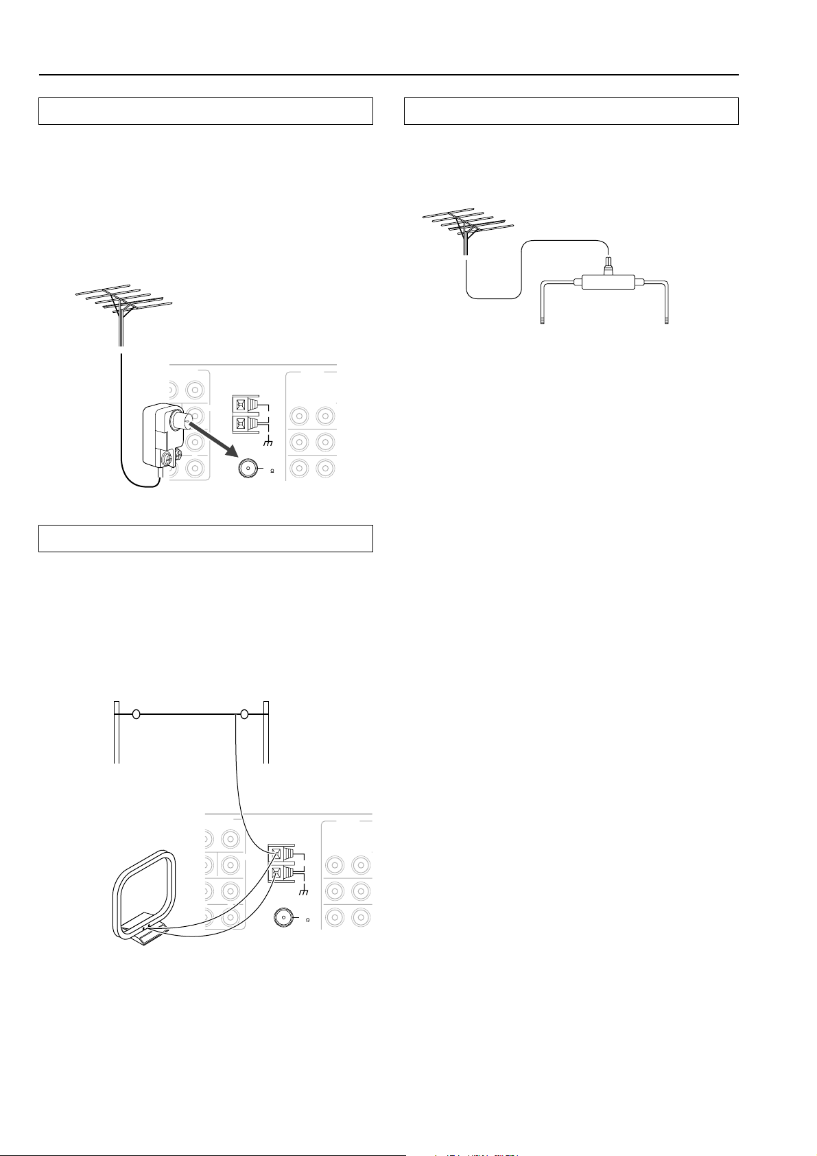
Connecting antennas
Connecting an FM outdoor antenna
Make sure to follow the general rules given below:
• Keep the antenna away from noise sources (neon signs, busy
roads, etc.).
• It is dangerous to put the antenna close to power lines. Keep it
well away from power lines, transformers, etc.
• To avoid the risk of lightning and electrical shock, grounding is
necessary. Follow item 14 of the “Important Safeguards” on
page 2 when you install the outdoor antenna.
RE OUT
L
ANTENNA
CENTER
L
AUDIO
L
R
AM
FM
75
Directional linkage
Do not use the same antenna for both FM and TV (or VCR)
reception since the FM and TV (or VCR) signals can interfere with
each other. If you must use a common FM/TV (or VCR) antenna, use
a directional linkage type splitter.
To TV (or VCR)To receiver
Connecting an AM outdoor antenna
If reception is poor with the indoor AM antenna, stretch out the
outdoor antenna (16 feet (5 meters) or more) above a window or
outside.
• Keep the indoor AM loop antenna connected. Do not remove it.
• To avoid the risk of lightning and electrical shock, grounding is
necessary. Follow item 14 of the “Important Safeguards” on
page 2 when you install the outdoor antenna.
Outdoor antenna
(Indoor)
AM loop antenna
RE OUT
L
ANTENNA
CENTER
L
AUDIO
L
R
AM
FM
75
24
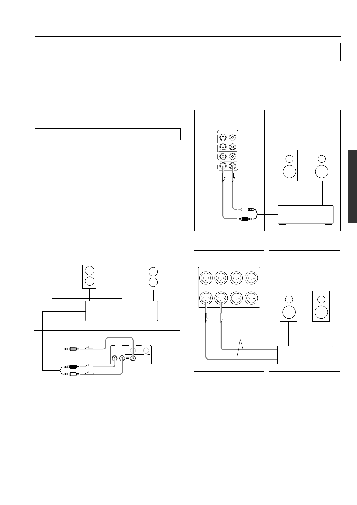
Connecting devices used in Zone 2
R
The DTC-9.4 allows you to watch and listen to two separate input
sources at the same time. This allows you to, for example, place
speakers and a television in two different rooms so that two or more
people can enjoy two different movies at the same time. The room
where the DTC-9.4 is actually located is referred to as the main room
while the separate room is referred to as the remote zone (Zone 2). In
addition, the IR IN/OUT terminal of the DTC-9.4 allows you to
control the DTC-9.4 from the remote zone (Zone 2) with the remote
controller even though the remote zone is physically separated. The
diagram below shows how to make the proper connections for the
remote zone.
When using the ZONE 2 OUT terminals
When you have connected all the speakers for 7.1-channel audio in
the main room, connect the speakers as shown below.
The ZONE 2 OUT terminal is a constant output. Connect to the
LINE input of the amplifier (CD, tape, etc.). Adjust the volume with
the amplifier connected to the ZONE 2 OUT terminal.
1. Connect the DTC-9.4 to the amplifier for the remote
zone.
2. Connect the remote zone speaker cables to the
speaker terminals on the amplifier.
3. Connect the DTC-9.4 to the monitor for the remote
zone.
When using the SURR BACK/ZONE 2 PRE OUT
terminals
If you are using a 5.1-channel speaker system in the main room, you
can connect the amplifier for the remote zone (Zone 2) to the open
SURR BACK/ZONE 2 PRE OUT terminals and connect the remote
zone speakers.
With this connection, select “Zone 2” for the Hardware Setup →
Surr Back/Zone 2 → Surr Back/Zone 2 setting in the Setup menu.
Remote Zone (Zone 2)Main Room
PRE OUT
L
R
DTC-9.4
FRONT
SUB
SURR
SURR
BACK/
ZONE 2
R
CENTE
L
Left (white)
Right (red)
Zone 2
Left
speaker
Power amplifier
Zone 2
Right
speaker
Remote Zone (Zone 2)
Zone 2
Left speaker
Zone 2 monitor
or projector
Zone 2
Right speaker
Zone 2 amplifier
Main Room
VIDEO
S VIDEO
MONITOR
OUT
ZONE 2
OUT
DTC-9.4
Right (red)
Left (white)
R
AUDIO
L
Note:
The ZONE 2 out terminals of the DTC-9.4 are of a fixed output
level.
SURR BACK / ZONE 2
RIGHT
DTC-9.4
PRE OUT
SURR BACK / ZONE 2
SURROUND
RIGHT
LEFT
XLR (balanced)
type cable
LEFTRIGHTCENTERSUBWOOFER
SURROUND
LEFT
Remote Zone (Zone 2)Main Room
Zone 2
Left
speaker
Power amplifier
Zone 2
Right
speaker
25
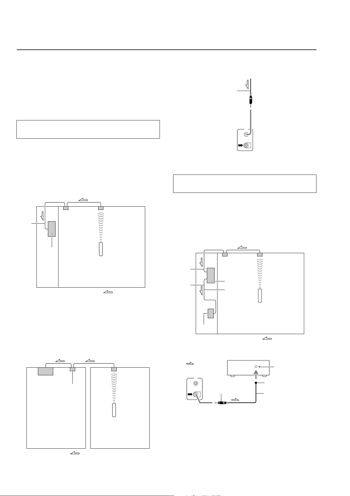
Operating components not reached by the
remote controller signals (IR IN/OUT)
In order to use the remote controller to control the DTC-9.4
from a remote location, you will need to prepare a multi-room
kit (sold separately) such as one of those given below:
• Onkyo’s Multi-Room System kits (IR Remote Controller
Extension System)
• Multiroom A/V distribution and control system such as those
from Niles
®
and Xantech
®
If the remote controller signal does not reach the
DTC-9.4 remote sensor
If the DTC-9.4 is located inside a cabinet or other enclosure where
the infrared rays from the remote controller cannot enter, then
operation with the remote controller will not be possible. In such a
case, it will be necessary to install a remote sensor at a location
outside of the cabinet for the infrared rays from the controller can
reach.
With this connection, select “Main” for the Hardware Setup → IR IN
Setup → Position setting in the Setup Menu (see page 52).
IR IN
Connecting
block
IR Receiver
Make the connection as shown below. Do not plug in any equipment
to the power outlet until all the connections are complete.
from connecting block
Mini plug cable
I R
IN
OUT
DTC-9.4
If the remote controller signal does not reach
other components
In this situation, you will need to use a commercially available IR
emitter. Connect the mini plug of the IR emitter to the IR OUT
terminal on the DTC-9.4 and then place the IR emitter on the remote
sensor of the component or facing it. When the IR emitter is
connected, only the signal input to the IR IN terminal is output to the
IR OUT terminal. The signal input from the remote sensor on the
front of the DTC-9.4 will not be output to the IR OUT terminal.
DTC-9.4
Remote controller
In the
cabinet
: Signal flow
The IR IN input allows you to control the DTC-9.4 from the remote
zone (Zone 2) with the remote controller even though the remote
zone may be on the other side of the building from the main zone.
The diagram below shows how to make the proper connections for
the remote zone.
With this connection, select “Zone 2” for the Hardware Setup → IR
IN Setup → Position setting in the Setup Menu (see page 52).
To IR IN
IR Receiver
DTC-9.4
Connecting
block
IR IN
IR OUT
Other
component
: Signal flow
I R
IN
OUT
DTC-9.4
block
DTC-9.4
IR Emitter
Mini plug
Remote controller
Other component
IR Emitter
IR ReceiverConnecting
: Signal flow
Remote control
sensor
Emitter
Mini plug cable
26
Remote controller
Zone 2 roomMain room
: Signal flow
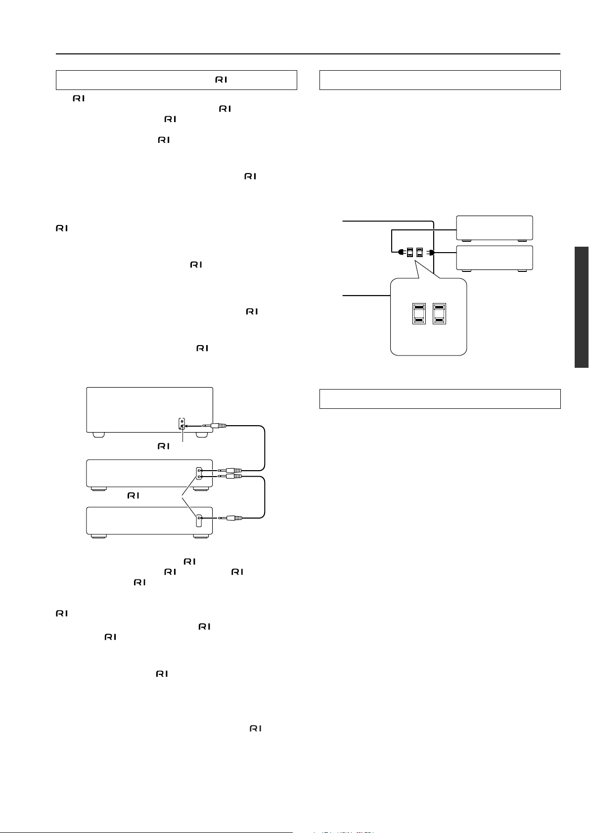
Miscellaneous Connections
AC 120 V 60 Hz
SWITCHED
TOTAL 120W 1A MAX.
AC OUTLETS
Connections for remote control ( )
The terminal on the DTC-9.4 is for connecting other Integra/
Onkyo components equipped with the same
component is connected to the
terminal, it can be operated by the
remote controller supplied with the DTC-9.4. In addition, when you
connect a component to the
terminal, you can also perform the
system operations given below.
Power on/ready function
When the DTC-9.4 is in the standby state, if an -connected
component is turned on, the DTC-9.4 also turns on and the input
source selected at the DTC-9.4 automatically switches to that
component.
Be aware that this function will not work if the power cord for the
-connected component is connected to the AC OUTLET on the
DTC-9.4, or if the DTC-9.4 has already been turned on.
Direct change function
When the play button is pressed at an
input source selected at the DTC-9.4 automatically changes to that
component.
Power off function
When the DTC-9.4 is placed in the standby state, all -connected
components are also automatically put into the standby state.
Also, if you press the ON button on the DTC-9.4 remote controller
while the DTC-9.4 is turned on, all
(DVD players, CD players, MD recorders, tuners, etc.) are also
turned on.
terminal. When a
-connected component, the
-connected components
Connecting the power cords from other devices
The DTC-9.4 is equipped with AC mains outlets for connecting the
power cords from other devices so that their power is supplied
through the DTC-9.4. By doing this, you can leave the connected
device turned on and have the Standby/On button on the DTC-9.4
turn on and off the device together with the DTC-9.4.
Caution:
Make sure that the total capacity of the components connected to the
DTC-9.4 does not exceed the capacity that is printed on the rear
panel (TOTAL 120W).
DTC-9.4
I R
IN
OUT
connector
Ex: Integra/Onkyo
CD player
connector
Ex: Integra/Onkyo
cassette tape deck
To connect components using the
terminal, simply connect a
remote control cable from this terminal to the terminal of the
other component. An
remote control cable with a 1/8-inch (3.5mm) miniature two-conductor plug comes with every cassette tape
deck, compact disc player, MD recorder, and DVD player that has an
terminal.
• When performing operations with
-connected components
using the system, do not use the remote zone (Zone 2).
• For remote control operation, the audio connection cables must
also be connected.
• If a component has two
terminals, you can use either one to
connect to the DTC-9.4. The other one can be used to daisy chain
with another component.
• With Integra/Onkyo DVD players, you can enter the preprogram code so that you can operate the DVD player directly
with the remote controller without connecting the
terminals
(see page 75).
RS232 port
The RS232 port is to be used in conjunction with an external
controller to control the operation of the DTC-9.4 by using an
external device.
Note:
When you use a MD recorder, connect the recorder to the TAPE
terminals on the DTC-9.4. In this case, change the input source
display name of the DTC-9.4 from “TAPE” to “MD” (see page 30).
27
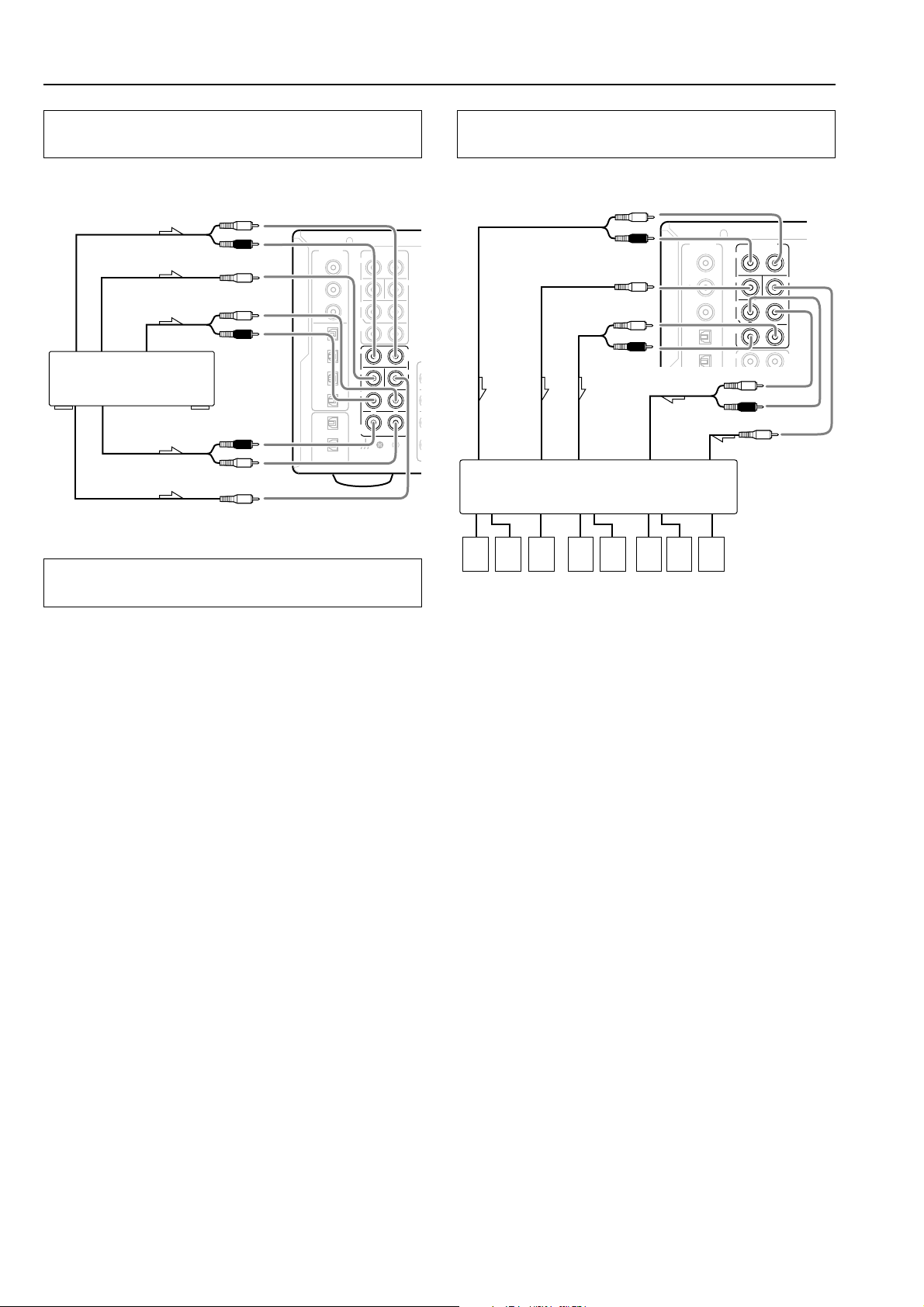
Miscellaneous Connections
T
R
C
Connecting to devices with analog multi channel
output
Connect a DVD player, MPEG decoder, or other component that has
a multi channel port for 5.1 channel or 7.1 channel output.
Front output
Subwoofer
Surround
Ex: DVD-Audio player/MPEG
decoder
Surround back
Center
L
R
L
R
R
L
to white
to Red
DIGITAL
INPUT
COAX
1
to Purple
2
to Blue
3
OPT
1
to Gray
2
3
4
OPT
1
to Tan
2
to Brown
DIGITAL
OUTPUT
to Green
FRONT
SUB
SURR
SURR
BACK/
ZONE 2
FRONT
SUB
SURR
SURR
BACK
PRE OUT
L
R
CENTE
R
L
MULTI
INPU
R
L
CENTER
R
L
GND
Connecting to an external device with 12V
TRIGGER terminal
These terminals are provided so that you can use the operation of the
DTC-9.4 control the operation of another externally connected
device. Connect the component to this 1/8-inch mini-jack terminal
and when the set input source is selected, the device will turn on. Set
the 12V TRIGGER terminal using the Setup menu: Input setup →
12V trigger (see page 60).
When the DTC-9.4 is in the ZONE 2 mode, the 12V TRIGGER
ZONE 2 terminal outputs at 12 V/100 mA.
The 12V TRIGGER OUT B (CONTROL LINK OUT) terminal on
the DTC-9.4 is for connecting to the Integra DTA-9.4 power
amplifier.
When the DTC-9.4 is connected to the DTA-9.4, the DTA-9.4 can be
turned on or entered into standby state in conjunction with the “on”
or “standby” states of the DTC-9.4.
The Dimmer function of the DTA-9.4 for the On indicator brightness
will also work in conjunction with the Dimmer function of the DTC-
9.4 for the display brightness. Use the mini-plug cable supplied with
the DTA-9.4 for connecting to the 12V TRIGGER IN terminal on
the DTA-9.4.
Connecting auxiliary power amplifiers with RCA
type connector
Connect your power amplifier to the PRE OUT jacks on the DTC-9.4.
Front
Subwoofer
Surround
back
Power amplifier
L
R
L
R
to White
to Red
DIGITAL
INPUT
COAX
1
to Purple
2
3
to Brown
OPT
1
to Tan
2
Surround
Center
FRONT
SUB
SURR
SURR
BACK/
ZONE 2
FRONT
PRE OUT
R
R
L
R
L
L
to Blue
to Gray
CENTER
MULTI
INPUT
to Green
87654321
1. Front left speaker
2. Front right speaker
3. Subwoofer
4. Surround back left/Zone 2
left speaker
Note:
For connections when you enjoy music and video in the remote room
(Zone 2), see page 25.
5. Surround back right/Zone 2
right speaker
6. Surround left speaker
7. Surround right speaker
8. Center speaker
28
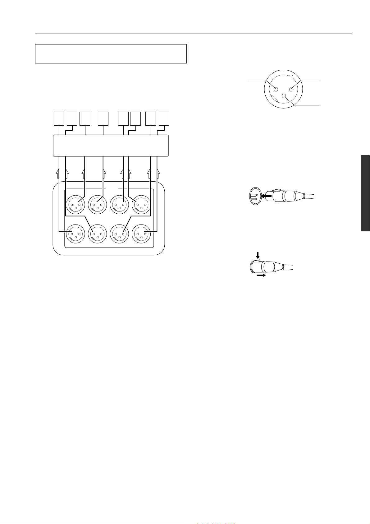
Miscellaneous Connections
Connecting power amplifiers with XLR type
connector
Connect your power amplifier to the PRE OUT jacks on the DTC-
9.4. If the jacks on your power amplifier are XLR (balanced) type
jacks, connect them to the jacks shown in the diagram given below.
3 8746521
Power amplifier
SURR BACK / ZONE 2
RIGHT
SURR BACK / ZONE 2
LEFT
PRE OUT
SURROUND
RIGHT
LEFTRIGHTCENTERSUBWOOFER
SURROUND
LEFT
These jacks are for connecting power amplifiers. If the jacks on your
power amplifier are XLR (balanced) type jacks, connect them here.
The pin assignments for these terminals are shown below.
2. non-inverting (+) 1. GND
3. inverting (-)
These pin assignments conform to the standards made by the Audio
Engineering Society. Check the instruction manual that came with
your power amplifier and verify that the input pin assignments are
compatible with those for the DTC-9.4.
1. Connecting the output terminal
Match the pins and insert the terminal until you hear a “click.”
Ensure that it is secure by gently pulling it.
2. Disconnecting tha output terminal
Pull out the cable (in the direction indicated by the arrow) while
holding down the connection cable button.
1. Surround back right/Zone 2
right speaker
2. Surround back left/Zone 2
left speaker
3. Subwoofer
4. Center speaker
5. Front right speaker
6. Front left speaker
7. Surround right speaker
8. Surround left speaker
Push
Note:
For connections when you enjoy music and video in the remote room
(Zone 2), see page 25.
29
 Loading...