

Page 1
DR-L50
Ref. No. 3745
SERVICE MANUAL
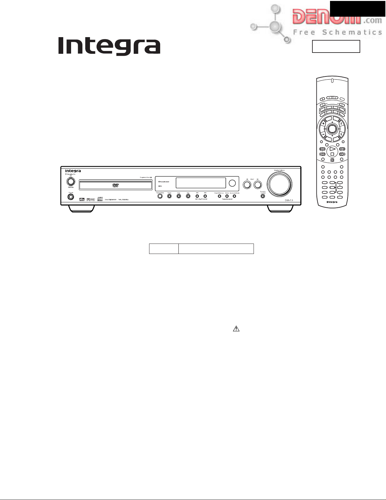
DVD RECEIVER
MODEL DSR-7.3
Aug, 2002
n
d
e
S
S
t
a
n
n
d
O
b
y
e
s
o
l
C
/
n
e
p
O
D
S
Step/
C
Tun
T-D/ ST
Repeat
Late Night
Audio
Last M Prog ram
RC-507M
e
S
l
e
t
c
u
t
o
p
r
n
I
d
o
e
M
r
T
a
v
p
c
e
e
R
D
V
D
r
i
e
s
p
m
l
a
m
i
y
D
p
e
e
l
u
M
n
e
e
n
M
u
p
o
T
Slow
H
R
p
u
e
t
e
t
S
u
u
r
n
p
n
I
V
T
A.Control
Surround
Subtitle FM Mode
Angle
Random
SP Setup Test Tone CH Sel
123
SW Mode
Distance
456
-
T
D Setup
IPM
Up/
789
+
0
10
--
---
/
-
RC
507
M
L
i
g
h
t
2
T
V
C
l
o
c
k
VOLENTER
t
Muting
-
A
B
Timer
Clear
Down
Search
Enter
Black model
120V AC, 60HzBMDD
SAFETY-RELATED COMPONENT
WARNING!!
COMPONENTS IDENTIFIED BY MARK ON THE
SCHEMATIC DIAGRAM AND IN THE PARTS LIST ARE
CRITICAL FOR RISK OF FIRE AND ELECTRIC SHOCK.
REPLACE THESE COMPONENTS WITH ONKYO
PARTS WHOSE PART NUMBERS APPEAR AS SHOWN
IN THIS MANUAL.
MAKE LEAKAGE-CURRENT OR RESISTANCE
MEASUREMENTS TO DETERMINE THAT EXPOSED
PARTS ARE ACCEPTABLY INSULATED FROM THE
SUPPLY CIRCUIT BEFORE RETURNING THE
APPLIANCE TO THE CUSTOMER.
www.denom.com
Page 2
SPECIFICATIONS
AMPLIFIER SECTION
Power Output (FTC) All channels 25 watts per channel min.
RMS. into 6 ohms two channel driven,
1,000 Hz with no more than 10% total
harmonic distortion.
Continuous power output (DIN)
All channels 21 watts per channel min.
RMS. into 6 ohms two channel driven,
1,000 Hz
Continuous Power output (EIAJ)
All channel 26 watts per channel min.
RMS. into 6 ohms two channel driven,
1,000 Hz
T otal Harmonic Distortion10 % at rated power
0.2 % at 1 watt output
IM Distortion 10 % at rated power
0.2 % at 1 watt output
Damping Factor 40 at 8 ohms
Input Sensitivity and Impedance
DIGITAL OPTICAL IN –21 to –15 dBm
LINE (TV/LINE, MD/CDR/TAPE) 200 mV/50 kohms
Output Level and Impedance
DIGITAL OPTICAL OUT –21 to –15 dBm
REC OUT (MD/CDR/TAPE)
PRE OUT (SUBWOOFER) 1 V, 470 ohms
Frequency Response 20 to 30,000 Hz : +/– 0.8 dB
Acoustic Control 1: +9 dB at 82 Hz
2: +9 dB at 82 Hz
+6 dB at 10,000 Hz
Signal-to-noise Ratio 100 dB (0.5 V INPUT LINE)
Muting –50 dB
200 mV, 2.2 kohms
DSR-7.3
DVD SECTION
Signal readout system Optical non-contact
Linear velocity 3.49 m/s (Single Layer)
Error correction system Reed Solomon Product Code
Signal system Standard NTSC
Regional restriction code South American area: 4
Output Level and Impedance
Composite 1.0Vp-p, 75 ohms
S-Video Y: 1.0 Vp-p, 75 ohms
Component Y: 1.0 Vp-p, 75 ohms
3.84 m/s (Dual Layer)
C: 0.286 Vp-p, 75 ohms
B, PR: 0.7 p-p, 75 ohms
P
Laser Semiconductor laser, wavelength 650 nm
Frequency response 10 Hz to 44 kHz (96 kHz)
Signal-to-noise ratio (digital audio) More than 100 dB
Audio dynamic range (digital audio) More than 93 dB
Harmonic distortion (digital audio) Less than 0.025%
Wow and flutter Below threshold of measurability
Operating conditions Temperature: 5 C to 35 C (41 F to 95 F),
TUNER SECTION
Tuning Range FM: 87.50 to 108.00 MHz (50 kHz steps)
Usable Sensitivity FM: Mono 11.2 dBf, 1.0 µV (75 ohms IHF)
50 dB Quieting Sensitivity FM: Mono 17.2 dBf, 2.0 µV (75 ohms)
Capture Ratio FM: 2.0 dB
Image Rejection Ratio FM: 40 dB
IF Rejection Ratio FM: 90 dB
Signal-to-noise Ratio FM: Mono 73 dB, IHF
Alternate Channel Att. (+/– 400 kHz) FM: Mono 55 dB, IHF
Selectivity FM:
AM Suppression Ratio FM: 50 dB
AM: 530 to 1710 kHz (10 kHz steps)
Stereo 17.2 dBf, 2.0 µV (75 ohms IHF)
AM: 30 µV
Stereo 37.2 dBf, 20.0 µV (75 ohms)
AM: 40 dB
AM: 40 dB
Stereo 67 dB, IHF
AM: 40 dB
50 dB, DIN
55dB, IHF
0.9 µV (75 ohms DIN)
23 µV (75 ohms DIN)
Harmonic Distortion FM: Mono 0.2 %
Frequency response FM: 30 to 15,000 Hz (+/– 1.0 dB)
Stereo Separation FM: 45 dB at 1,000 Hz
Stereo Threshold FM: 17.2 dBf, 20 µV (75 ohms)
Output FM: 500 mV
GENERAL
Power Supply
Power Consumption : 130 W
Power Consumption (standby mode) : 2.0 W
(*) when clock display is on
AC 120 V, 60 Hz
: 29 W (*)
Dimensions (W x H x D)
Weight
Operation status: Horizontal
Stereo 0.3 %
AM: 0.7 %
30 dB at 100 to 10,000 Hz
AM: 150 mV
435 81 366 mm (171/8 33/16
7.0 kg (15.4 lb.)
147/16 ins.)
Specifications and features are subject to change without notice.
www.denom.com
Page 3
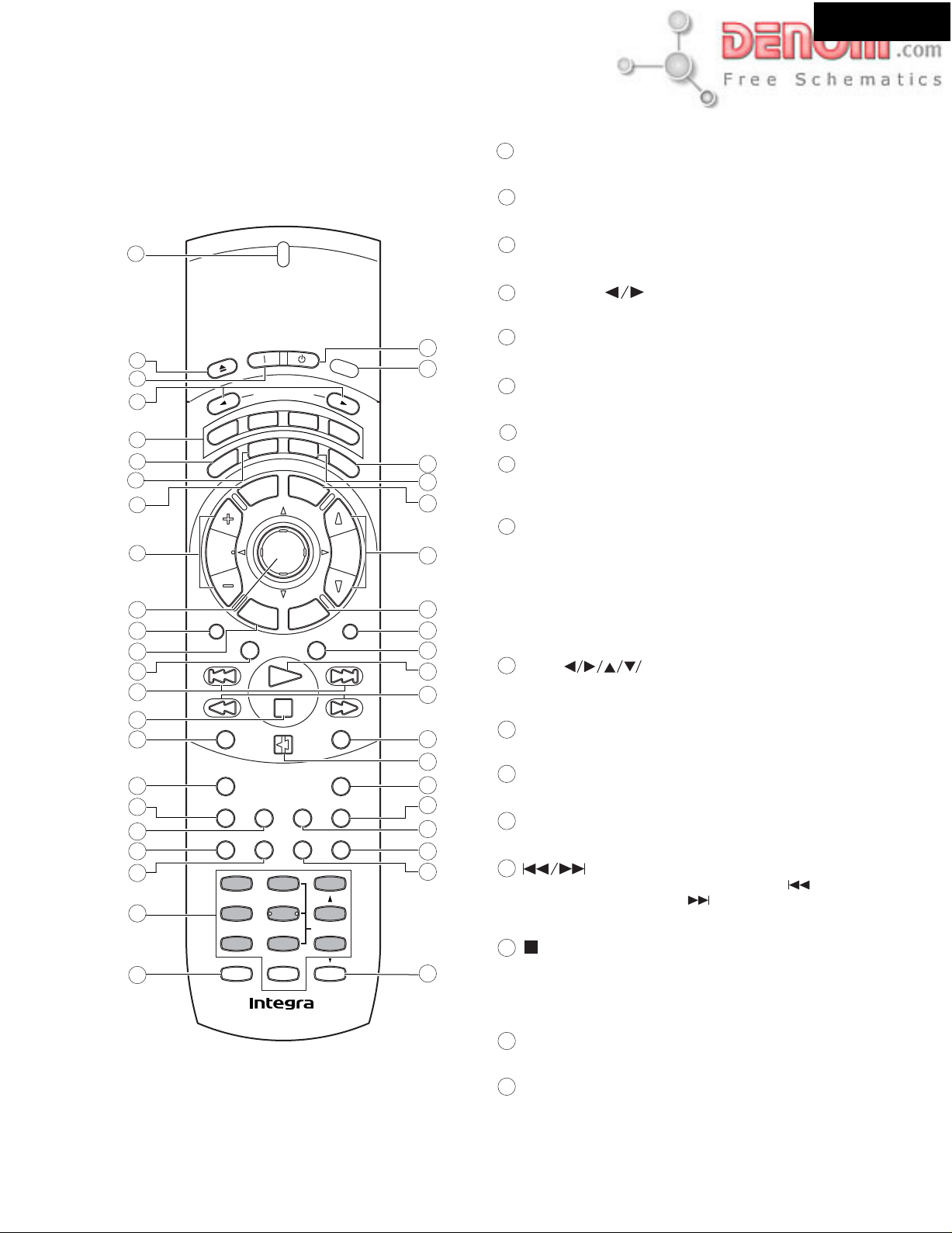
REMOTE CONTROLLER-1
RC-507M
DSR-7.3
Explanations on this page are for controlling the DVD receiver. The
supplied remote controller is a useful tool to help you operate your
home theater.
1
n
d
e
S
S
t
a
n
n
p
c
m
e
u
r
t
u
M
r
v
r
e
u
n
n
Distance
-
T
D Setup
RC
S
o
-
507
d
b
y
e
l
e
c
t
o
r
d
e
T
a
p
e
D
i
s
p
l
a
y
M
e
n
u
p
u
t
t
e
S
u
p
n
I
V
T
A.Control
Subtitle FM Mode
Random
Up/
Search
0
Enter
M
Down
L
C
A
Timer
Clear
i
g
h
2
T
V
l
o
c
VOLENTER
Muting
-
B
24
t
k
25
26
27
28
29
30
31
32
33
34
35
36
37
38
39
40
41
42
7
10
11
12
13
14
15
16
17
18
19
20
21
22
23
2
p
O
O
e
s
o
l
C
/
n
e
3
n
4
5
6
8
Step/
9
T-D/ ST
Late Night
I
e
R
D
V
D
m
i
D
p
e
e
l
S
M
p
o
T
Slow
H
C
Tun
R
e
t
Surround
Repeat
Angle
Audio
Last M Program
SP Setup Test Tone CH Sel
123
SW Mode
456
IPM
789
+
10
--
---
/
1
Send indicator
Lights red when sending a signal.
2
Open/Close button
Opens and closes the disc tray.
3
On button
Turns on the DVD Receiver.
Input Selector buttons
4
Press to select the input source.
5
Mode buttons
For selecting the component to be operated by the remote controller.
Sleep button
6
For setting the sleep timer.
Dimmer button
7
For adjusting the brightness of the front display.
Top Menu button
8
Press to call up the top menu programmed on the DVD. Depending
on the DVD, the top menu may be identical to the DVD menu.
(Mode Recvr is selected) Tun
9
+/-
buttons
For selecting a tuner preset channel.
(Mode DVD is selected) Step/Slow
Press Step/Slow
hold Step/Slow
frame, press Step/Slow
by frame and Step/Slow
+/- during playback to view still frame. Press and
+/-
during playback to view slow playback. In still
+
to advance DVDs and Video CDs frame
-
to back up a few frames at a time (DVD
+/-
buttons
only)
10
Cursor( ENTER)
Use to move through the options on menu screens. Press to enter
settings.
T-D/ST button
11
Press to switch the listening mode between "STEREO" and
"THEATER-DIMENSIONAL"
12
Return button
Use to go one menu back (current settings are maintained). Use Return
when you do not want to change the option setting in a menu.
13
Surround button
Press to select the surround mode.
buttons
14
During playback of DVD, CD and Video CD, press to go back
to a previous chapter/track and to advance to the next chapter/
track.
button
15
Press to stop playback (DVD). Pressing once enables playback to
resume from a point shortly before the location where it was
stopped. Pressing twice causes the disc to return to the beginning
of the disc when playback starts again.
To control the DVD receiver , press Mode DVD or Mode
Recvr first. Press Mode DVD to operate the DVD section, or
Mode Recvr to operate the receiver section. Functions of
grayed buttons in the illustration vary depending on the
mode .
www.denom.com
Repeat button
16
Use to set the repeat mode.
17
Late Night button
Press to change the late night setting.
Page 4
REMOTE CONTROLLER-2
RC-507M
Audio button
18
Press repeatedly to select one of the audio languages programmed
on a DVD.
For Video CD and MP3, each press changes the audio output as
follows.
Stereo 1/L(Left) 2/R(Right)
DSR-7.3
A-B button
35
Press at the beginning and end of the section you want to repeat
or to mark a location you want to return to.
button
36
Press to pause disc playback. Press again to resume playback.
19
Angle button
Some DVDs are recorded with various camera angle playback
options. Press Angle repeatedly to display different camera angles.
20
Last M button
You can resume DVD or Video CD playback from the point you last
watched even if the disc is removed from the DVD receiver. Press
Last M during playback to set a Last Memory Point. When you
want to resume playback of that disc, press Last M in the stop
mode and playback starts from the memorized point. Last Memory
locations can be stored for up to 5 DVDs and 1 Video CD.
Program button
21
You can program titles, chapters or tracks to play back in desired
order. Programs can be a maximum of 24 steps.
Number buttons (1-9, +10, 0)
22
Use to perform direct title/folder and chapter/track searches, and to
input numerical values. Press Mode Rcvr for additional functions
+10/--/--- button
23
Press to input numbers over 10.
24
Standby button [34, 43, 45, 62]
Put the DVD Receiver in standby.
Light button
25
Illuminates the buttons. This button is useful when using the
remote controller in dark locations. When pressed, the buttons on
the remote controller light green.
Clock button
26
Press to view the clock display.
27
Display button
Press to change the information being displayed.
28
Menu button
Use to display or close the DVD menu or MP3 Navigator screen.
VOL buttons
29
For adjusting the volume.
30
Setup button
Press when the DVD Receiver is in either play or stop mode to
open and close the Setup screen.
Muting button
31
Activates the mute function.
A. Control button
32
Press to change the acoustic mode to boost the super bass/high
frequency sounds.
button
33
Press to start or resume playback.
buttons
34
During playback of DVD and Video CD, press to perform fast
forward scanning or to perform fast reverse scanning of DVD
and Video CD. When a CD or MP3 is loaded, audio scanning is
performed.
Timer button
37
Press to activate a timer function or to set a timer program.
38
FM Mode button
For AM/FM input, press to switch between FM Stereo auto and
mono.
39
Subtitle button
Press repeatedly to select one of the subtitle languages
programmed on DVD or to turn the subtitles off.
Clear button
40
Works in conjunction with a number of player functions. Use to
cancel repeat and random playback, and to edit programs.
Random button
41
Press to play chapters/tracks in random order.
42
Search/Enter button
Press to perform a title/folder, chapter/track or elapsed time
search. Press to confirm when controlling a connected TV.
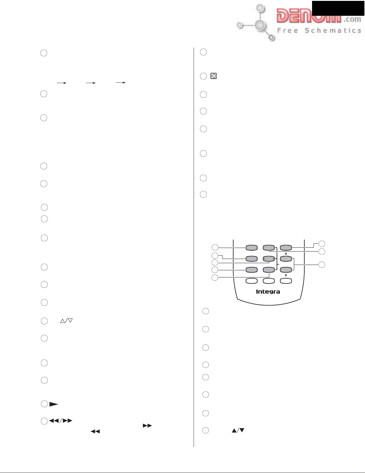
Press Mode Recvr to use the following (gray) buttons
Other buttons have the same functions as when Mode DVD
button is pressed.
1
2
3
4
5
1
SP Setup button
SP Setup Test Tone CH Sel
123
SW Mode
Distance
456
-
T
D Setup
IPM
789
+
10
--
---
/
-
RC
507
Down
Up/
Search
0
Enter
M
6
7
8
Press to select the optimum speaker configuration.
2
SW Mode button
Press to select the subwoofer mode.
Distance button
3
For setting the distances for each speaker.
4
IPM (Intelligent Power Management) button
Activates the IPM function.
5
T-D Setup
For setting the T-D parameters.
6
CH Sel button
Selects a speaker for changing the speaker output level.
Test Tone button
7
Outputs a test tone for setting speaker levels.
8
Up/Down buttons
Press to adjust the value.
www.denom.com
Page 5

REMOTE CONTROLLER-3
RC-507M
Preparing the Remote Controller
Switching the remote controller function modes
Some buttons on the remote controller have two or more functions.
To set the functionality of these buttons, press oneof the six Mode (DVD, Recvr, Tape, TV) buttons in advance.
The function mode remains the same until another Mode button is pressed.
(Details about the functions and the related function modes are explained in each section.)
n
d
e
S
S
t
a
n
n
d
O
b
e
s
o
l
C
/
n
e
p
O
D
V
D
p
e
e
l
S
Step/
Slow
H
C
Tun
T-D/ ST
Surround
y
L
i
g
h
t
e
S
l
e
t
c
u
t
o
p
r
n
I
c
e
R
m
i
D
M
p
o
T
R
e
t
u
2
d
o
e
M
r
T
a
v
p
e
T
V
D
r
i
e
s
p
m
l
a
y
C
l
o
c
k
u
M
n
e
e
n
u
VOLENTER
p
u
t
t
e
S
u
r
n
p
n
Muting
I
V
T
A.Control
Mode buttons
d
o
e
M
r
T
a
v
c
e
R
D
V
D
p
e
T
V
DSR-7.3
Repeat
Late Night
Subtitle FM Mode
Angle
Audio
Random
Last M Progra m
SP Setup Test Tone CH Sel
123
SW Mode
Distance
456
-
T
D Setup
IPM
789
+
10
0
--
---
/
-
RC
507
M
-
B
A
Timer
Clear
Down
Up/
Search
Enter
Press Mode DVD first before operating the
built-in DVD player.
d
o
e
M
r
T
a
v
c
e
R
D
V
D
p
e
T
V
Press Mode Recvr first before operating the speaker setting
and sound related operations.
d
o
e
M
r
T
a
v
c
e
R
D
V
D
p
e
T
V
Press Mode Tape first before operating the z-connected
Integra/Onkyo cassette tape deck, MD recorder or CD recorder.
Press Mode TV first before operating your TV.
To operate the TV with the supplied remote controller, you
need to let the remote controller learn the TV remote control signals.
www.denom.com
Page 6

DSR-7.3
EXPLODED VIEW
A103
A103
A104
A101
F9001
U4
A019
A037
A105
E3
A017
P22
P1001
U14
P61
A023
A019
E1
A016U17
A039
A110
T9001
P51
U16
A044
E2
A041
A013
A019
A017
A019
A057
A017
A019
A019
A045
P21
U15
A015
U10
A019
Z1
A001
A019
A019
A027
U1
A033
A019
A019
A019
U12
U6
U11
U7
U8
A019
A029
A019
A069
F9501
U3
U13
A019
A027
A025
A019
A069
A049
A069
A073
U2
A067
A051
A069
A065
A047
A109
A117
A003
A005
A022
A007
A019
A003
A005
A011
A009
www.denom.com
A019
U5
A112
A111
A055
A505
A115
A119
A059
A103
DSR-7.3
A063
A061
Page 7
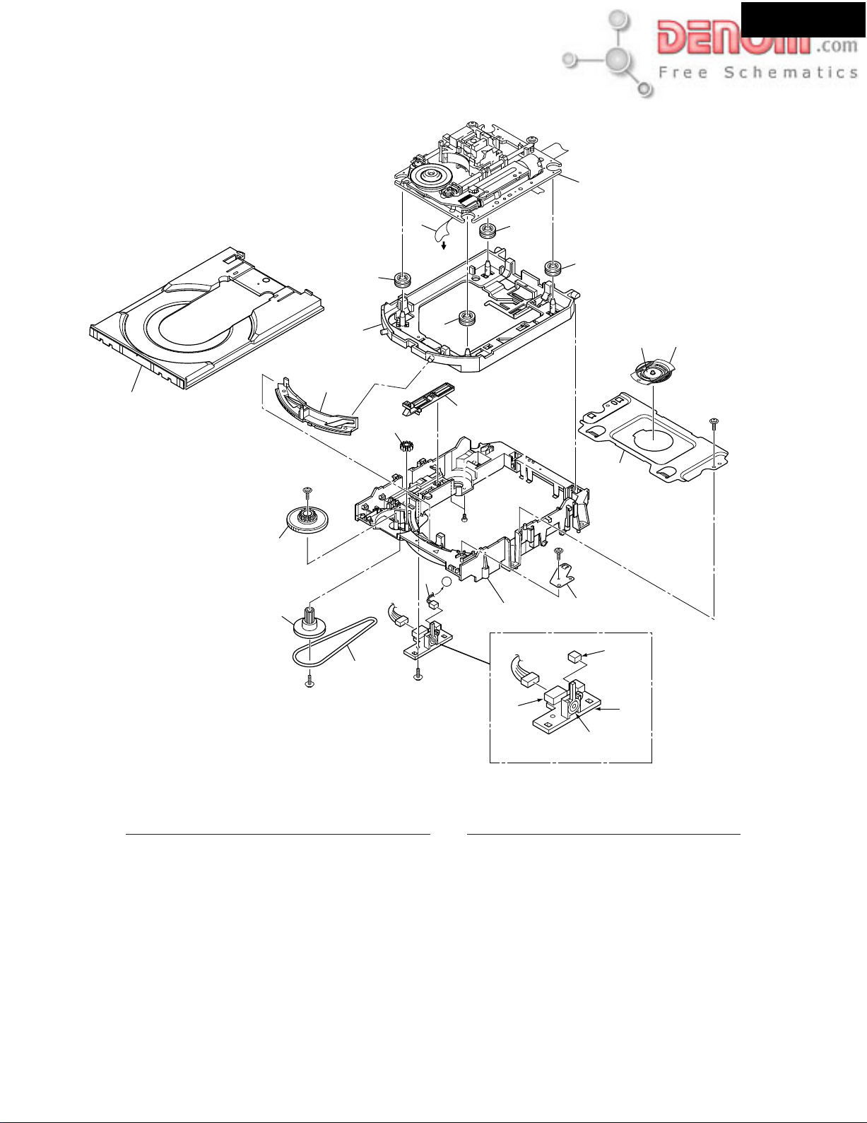
EXPLODED VIEWS OF MECHANISM-1
DVD MECHANISM:DB-VLD304
Daifree
GEM1036
6
To DVDM
8
CN151
DSR-7.3
2
Refer to
"EXPLODED VIEWS OF MECHANISM-"2
8
8
23
15
14
Lubricating Oil
12
GYA1001
13
8
20
18
A
17
16
19
A
11
10
1c
9
1d
1a
1b
PARTS LIST
No. Description Part No. No. Description Part No.
Float Base DVD
Loading switch PC board
1a
Switch
1b
2P Socket
1c
5p Socket
1d
Traverse mechanism assy
2
Flexible Cable (26P)
6
Float Rubber
8
Belt
9
Stabilizer
10
Loading Base
11
VNP1836
VSK1011
S2B-PH-K
S5B-PH-K
VXX2782
VDA1864
VEB1327
VEB1328
VNE2253
VNL1917
www.denom.com
12
13
14
15
16
17
18
19
20
23
Drive Cam
Gear Pulley
Loading Gear
Drive Gear
SW Lever
Clamper Plate
Bridge
Clamper
Tray
VNL1918
VNL1919
VNL1921
VNL1922
VNL1923
VNL1925
VNE2251
VNE2252
VNL1924
VNL1920
Page 8
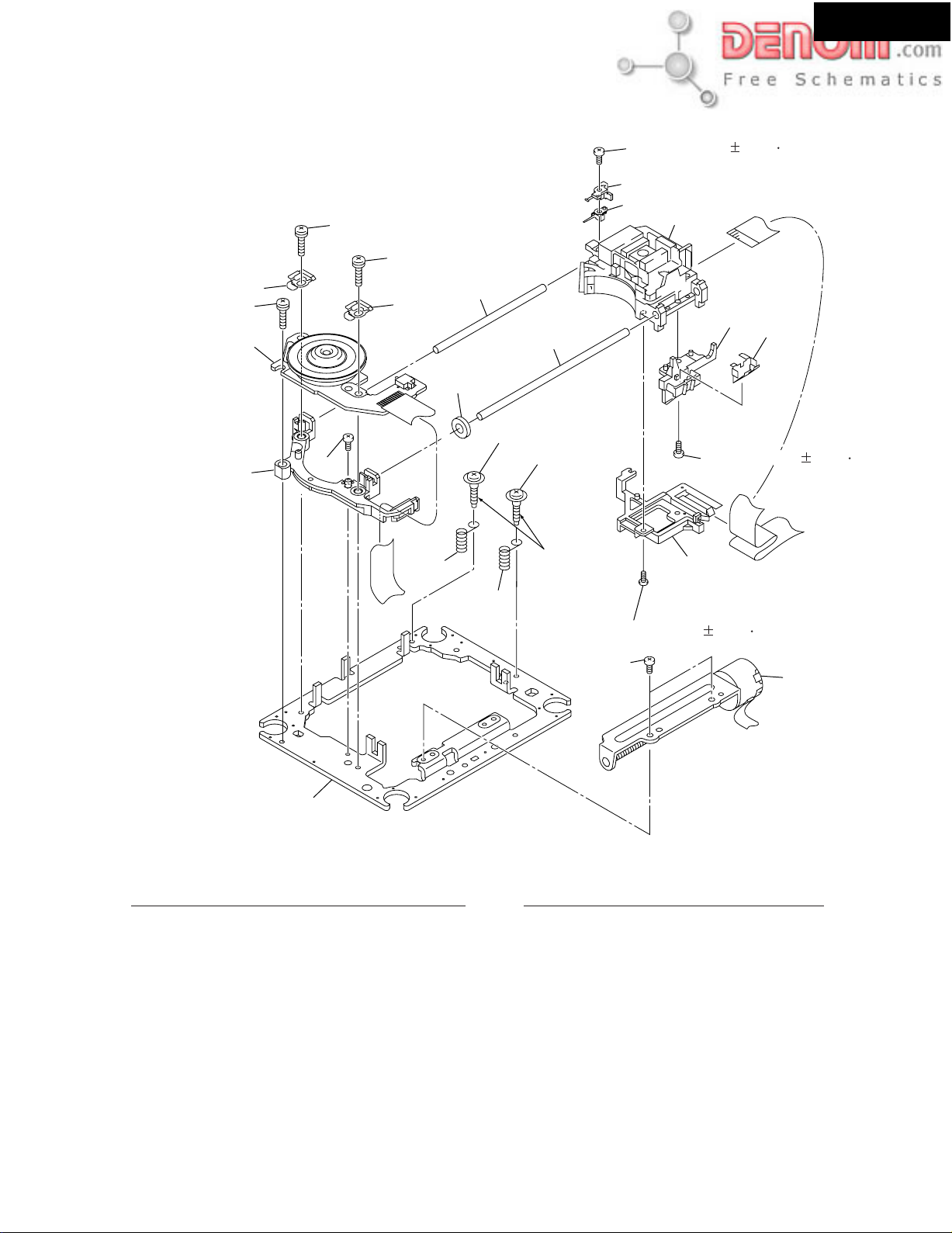
EXPLODED VIEWS OF MECHANISM-2
DVD MECHANISM:DB-VLD304 (TRAVERSE UNIT)
18
18
(Torgue:0.12 0.01N m)
17
12
8
3
DSR-7.3
18
13
10
1
16
10
7
14
6
19
(Adjustment Screw)
4
(Adjustment Screw)
4
5
Screw tight
(Torgue:0.12 0.01N m)
17
16
5
17
15
9
(Torgue:0.12 0.01N m)
2
Not supplied.
PARTS LIST
No. Description Part No. No. Description Part No.
1
Spindle Motor
2
Stepping Motor
3
Pickup Assy-S
4
Skew Screw
5
Skew Spring
6
Guide Bar
7
Sub Guide Bar
8
Hold Spring
VXM1088
VXM1090
OXX8003
VBA1080
VBH1335
VLL1514
VLL1515
VNC1017
www.denom.com
Joint Spring
9
Support Spring
10
Mechanism Chassis
11
Slider
12
Spacer
13
Joint
14
FFC Holder
15
Screw
16
Screw
17
Screw
18
Damper Sheet
19
VNC1019
VNC1020
--VNL1811
VNL1913
VNL1914
VNL1915
BBZ20P050FZK
OBA8009
PMA26P100FMC
VEB1335
Page 9

EXPLODED VIEW PARTS LIST
DSR-7.3
REF NO. NAME DESCRIPTION QT'Y PART NO.
A001 CHASSIS . 1 27100426
A003 BOTTOM LEG (AS) 4 27175392
A005 SCREW 3TTW+8B(BC) 4 831430088
A007 HOLDER KGLS-18RF 2 27190657
A009 HOLDER KGLS-10RF 3 27190428A
A011 HOLDER KGPS-10RF 4 27190813
A013 RETAINER (MB) 1 27141821
A015 BRACKET (SHLD) 1 27130888A
A016 BUSHING KG-016L 1 28170031
A017 TAPE TAPE(CROSS-16U) 1 29110083
A019 SCREW 3TTB+8B 49 838130088
A022 CAP (SCREW) 1 28330135A
A023 HOLDER MSPLS-3 3 27191177
A025 HEAT SINK 175 RG-418378 1 27160515
A027 BRACKET (H) 2 27130889
A029 BRACKET BRACKET 1 27130745
A033 SCREW 3TTB+16S(BC) 2 838430167
A037 SCREW 3TTW+8B(BC) 1 831430088
A039 SCREW 4TTC+6C(BC) 4 830440069
A041 ISO PLT (B) 1 28175288
A044 ISO PLT (T) 1 28175292
A045 RIVET P-RIVET NRP-345 4 880009
A047 F BRACKET AS 1 27111298
A049 TAPE . 2 29110161
A051 KNOB (ACC)AS 1 28326034
A055 CLEAR PLT . 1 28191974
A057 LABEL(DVD2) .. 1 29362648
A059 KNOB (VOL) 1 28326035
A061 DOOR . 1 28148479A
A063 PLATE (DVD) 1 27262651
A065 COVER . 1 28184849
A067 LABEL (PATENT) 1 29362760A
A069 SCREW 3TTB+8B(BC) 22 838430088
A073 LABEL (COVER) 1 29362772
A101 REAR PANEL UDD1N 1 27123020A
A103 SCREW 3TTB+8B(BC) 25 838430088
A104 SCREW 4TTB+8C(BC) 1 838440089
A105 SCREW 5STP+10BQ(BC) 3 833450102
A110 LABEL (PT) 1 29362762
A109 F PANEL . 1 27212438
A111 FACET (STBY) 1 28198930
A115 BADGE 1 28135278
A112 GUIDE (STBY) 1 27268049
A119 FACET (REC) 1 28198840
A117 GUIDE (INPUT) 1 27268063
A505 LABEL HOOKUP-INTEGRA 1 29363195
E1 FAN D06T-24TH 1 24502313
E2 CLIP CS-1U 1 27255004
E3 WIRE TIE BINDER(CLAMPER)UL 4 260208
F9001 FUSE 2.5A-UL/T-237 1 252160
F9501 FUSE 4A-SE-EAK FUSE 1 252077
P1001 FFC NCFC7-150512 1 2047150512
P21 FFC NCFC4-30029 1 204430029
P22 FFC NCFC4-30029 1 204430029
P51 SOCKET AS NSAS-10P0997 1 20022391010
P61 FFC NCFC4-171012 1 2044171012
T9001 P TRANS NPT-1455D 1 2301657
U17 TUNER UNIT TFCE1U114B 1 240134A
U16 PWB AS DB-VPB313/XJ 1 24150033
Z1 DVD M DB-VLD304 1 24801015
U1 DSP AND MICROPROCESSOR PC board NADG-7636-1
U2 DISPLAY PC board NADIS-7637
U3 STANDBY SWITCH PC board NASW-7638
U4 POWER SUPPLY PC board NAPS-7640
U5 PHONES JACK PC board NAETC-7641
U6 CONNECTOR PC board NAETC-7642
U7 CONNECTOR PC board NAETC-7643
U8 CONNECTOR PC board NAETC-7644
U10 ISOLATION PC board NAETC-7760
U11 HOLDER PC board
U12 THERMISTOR PC board
U13 MAIN PC board
U14 TRANSFORMER TERMINAL PC board
U15 DVD CONNECTOR PC board
NAETC-7639
NAETC-7645
NAAR-7646
NAPS-7647
NAETC-7649
1
1A952536-1G
1
1A952537-1G
1
1A952538-1G
1
1A952540-1G
1
1A952541-1G
1
1A952542-1G
1
1A952543-1G
1
1A952544-1G
1
1A952560-1G
1
1A952539-1G
1
1A952545-1G
1
1A952546-1G
1
1A952547-1G
1
1A952549-1G
1/8 PAGE
PACKING PARTS LIST
A401 PAD . 6 29092068
www.denom.com
Page 10

A405 SHEET . 1 29095847
A407 TAPE (SEROHAN)NITTO NO.29 1 29110149
A409 PP TAPE W48 OPP TAPE 1 29110148
A411 POLY BAG 350*250 2 29100097-1A
A417 LABEL (SP CABLE) 1 29363059A
A419 SHEET (CORNER) 4 29095935
A501 CARTON DSR-7.3 1 29053957
A5031 UPC LABEL . 1 29363229
A507 WRNTY CARD (INTEGRA) 1 29365089
A901 BATTERY UM-3 1 3010054
A902 ANT COIL NMA-3057 1 232140
A911 CORD AS (S CORD) or 1 2010380 or
CORD AS TPX3000 1 2010360
A912 PIN CORD AS RCA-3P(YWR) or 1 2010359 or
PIN CORD AS RCA-3P(YWR) or 1 2010359TAIDA or
PIN CORD AS RCA-3P(YWR) 1 2010359TES
A913 FM ANT AS Type D 1 292160
A921 REMO CON RC-507M 1 24140507
A931 INS MANUAL E(DSR-7.3) 1 29343408
P9001 AC CORD AS-UC-2 1 253297KAW
PC BOARD PARTS LIST
U1 DSP AND MICROPROCESSOR PC BOARD (NADG-7636-1G)
REF NO. NAME DESCRIPTION Q'TY PART NO.
Q3001 IC BD3811K1 1 22241761R3
Q3101 IC NJM4565V 1 22241554R2
Q3113 IC NJM4565V 1 22241554R2
Q3201 IC NJM4565V 1 22241554R2
Q8001 IC MPD784225GC-182-8BT 1 22241875R3
Q8301 IC NJM4565V 1 22241554R2
Q8302 IC NJM4565V 1 22241554R2
Q8303 IC NJM4565V 1 22241554R2
Q8304 IC NJM4565V 1 22241554R2
Q8305 IC NJM4565V 1 22241554R2
Q8306 IC NJM4565V 1 22241554R2
Q8307 IC NJM4565V 1 22241554R2
Q8308 IC NJM4565V 1 22241554R2
Q8309 IC NJM4565V 1 22241554R2
Q8401 IC AK4586 1 22241620R3
Q8451 IC TC7WU04FU 1 22240935R2
Q8501 IC CS493292-CL 1 22241455R2
Q8601 IC TC74VHC574FT 1 22274574ER2TO
Q8602 IC TC74VHC574FT 1 22274574ER2TO
Q8603 IC TC74VHC74FT 1 22274074ER2TO
Q8611 IC MX27L2000TC-12 1 18093002618AD
(Q8611) IC MX27L2000TC-12 (1) (22241809R3)
Q8651 IC TC74VHC541FT 1 22274541ER2TO
Q8671 IC TC74HCT7007AF 1 222740077R2TO
Q8691 IC BA33C25FP 1 22241778R2
Q8711 PHT CPL ON3131-R 1 24120044
Q3111 TR RN1441 1 2215410R2
Q3112 TR RN1441 1 2215410R2
Q3114 TR RN1441 1 2215410R2
Q3115 TR RN1441 1 2215410R2
Q3116 TR DTA114EE 1 2216710R2
Q3202 TR DTA114EE 1 2216710R2
Q3203 TR RN1441 1 2215410R2
Q8023 TR DTA124EE 1 2216490R2
Q8060 TR DTC144EE 1 2216390R2
Q8081 TR 2SA1774 1 2216410R2
Q8082 TR DTC114EE 1 2216730R2
Q8712 TR DTC114EE 1 2216730R2
Q8713 TR DTC114EE 1 2216730R2
Q8851 TR 2SC4617 1 2216540R2
D3001 ZENER D UDZ6.8B or 1 224490680R2 or
ZENER D UDZS6.8B ( 1) 224550680R2
D3002 ZENER D UDZ6.8B or 1 224490680R2 or
ZENER D UDZS6.8B ( 1) 224550680R2
D3111 C-DIODE 1SS355 1 223269R2
D3201 C-DIODE 1SS355 1 223269R2
D3202 C-DIODE 1SS355 1 223269R2
D8001 C-DIODE 1SS355 1 223269R2
D8002 C-DIODE 1SS355 1 223269R2
D8023 C-DIODE 1SS355 1 223269R2
D8024 ZENER D UDZ5.1B 1 224490510R2
D8060 C-DIODE 1SS355 1 223269R2
D8061 C-DIODE 1SS355 1 223269R2
D8062 ZENER D UDZ7.5B 1 224490750R2
D8401 C-DIODE 1SS355 1 223269R2
D8402 C-DIODE 1SS355 1 223269R2
D8711 C-DIODE 1SS355 1 223269R2
D8851 C-DIODE 1SS355 1 223269R2
2/8 PAGE
www.denom.com
Page 11

D8852 C-DIODE 1SS355 1 223269R2
L8001 CHOKE COIL NCH-1479 1 231237K470R2
L8401 CHOKE COIL NCH-1471 1 231237M022R2
L8402 CHOKE COIL NCH-1471 1 231237M022R2
L8403 CHOKE COIL NCH-1471 1 231237M022R2
L8404 CHOKE COIL NCH-1471 1 231237M022R2
L8451 CHOKE COIL NCH-1479 1 231237K470R2
L8501 CHOKE COIL NCH-1471 1 231237M022R2
L8502 CHOKE COIL NCH-1471 1 231237M022R2
L8601 CHOKE COIL NCH-1479 1 231237K470R2
L8691 CHOKE COIL NCH-1479 1 231237K470R2
X8001 CRYSTAL HC-49/U03C12.500MHz 1 3010362R2
X8451 CERA LOCK CSTCV12.2MTJ0C4 1 3010324R2
C1002 VR C CE04W50V-3.3M(VR) 1 394680337
C1003 VR C CE04W50V-2.2M(VR) 1 394680227
C3013 VX C CE04W16V-10M(VX) 1 393341007
C3014 VX C CE04W16V-10M(VX) 1 393341007
C3015 VX C CE04W16V-10M(VX) 1 393341007
C3016 VX C CE04W16V-10M(VX) 1 393341007
C3017 VX C CE04W16V-10M(VX) 1 393341007
C3018 VX C CE04W16V-10M(VX) 1 393341007
C3021 VR C CE04W16V-10M(VR) 1 394641007
C3022 VR C CE04W16V-10M(VR) 1 394641007
C3023 MY C MY92-50V-472J 1 371124724
C3024 MY C MY92-50V-472J 1 371124724
C3025 MMT C MMT50V-224J 1 375522244
C3026 MMT C MMT50V-224J 1 375522244
C3027 MMT C MMT50V-224J 1 375522244
C3028 MMT C MMT50V-224J 1 375522244
C3029 MMT C MMT50V-154J 1 375521544
C3030 MMT C MMT50V-154J 1 375521544
C3031 MMT C MMT50V-154J 1 375521544
C3032 MMT C MMT50V-154J 1 375521544
C3111 VX C CE04W16V-10M(VX) 1 393341007
C3112 VX C CE04W16V-10M(VX) 1 393341007
C3113 VX C CE04W16V-10M(VX) 1 393341007
C3115 TF C ECQ-B50V-103J 1 374721034
C3116 VX C CE04W16V-47M(VX) 1 393344707
C3118 VR C CE04W50V-2.2M(VR) 1 394680227
C3121 CERA C CK45F50V-223Z 1 335622230
C3122 CERA C CK45F50V-223Z 1 335622230
C3201 VR C CE04W16V-10M(VR) 1 394641007
C3202 VR C CE04W16V-10M(VR) 1 394641007
C3203 VR C CE04W16V-10M(VR) 1 394641007
C3206 VR C CE04W16V-10M(VR) 1 394641007
C3207 VR C CE04W16V-10M(VR) 1 394641007
C8001 VR C CE04W6.3V-100M(VR) 1 394621017
C8003 EDL C FMC0H104Z 1 3000120
C8004 VR C CE04W6.3V-100M(VR) 1 394621017
C8059 VR C CE04W50V-1.0M(VR) 1 394680107
C8070 TRIMMER NTC-45P10 1 3060011
C8404 VR C CE04W6.3V-47M(VR) 1 394624707
C8406 VR C CE04W6.3V-220M(VR) 1 394622217
C8410 VR C CE04W16V-22M(VR) 1 394642207
C8411 VX C CE04W16V-10M(VX) 1 393341007
C8412 VX C CE04W16V-10M(VX) 1 393341007
C8414 VR C CE04W6.3V-47M(VR) 1 394624707
C8421 VX C CE04W16V-47M(VX) 1 393344707
C8422 VX C CE04W16V-47M(VX) 1 393344707
C8423 VX C CE04W16V-10M(VX) 1 393341007
C8424 VX C CE04W16V-10M(VX) 1 393341007
C8425 VX C CE04W16V-47M(VX) 1 393344707
C8426 VX C CE04W16V-47M(VX) 1 393344707
C8503 VR C CE04W6.3V-47M(VR) 1 394624707
C8507 VR C CE04W6.3V-47M(VR) 1 394624707
C8604 VR C CE04W6.3V-47M(VR) 1 394624707
C8692 VR C CE04W6.3V-47M(VR) 1 394624707
C8693 VR C CE04W6.3V-47M(VR) 1 394624707
C8712 VR C CE04W6.3V-100M(VR) 1 394621017
P1001A SOCKET NSCT-15P1609 1 25051822
P3001 PIN JACK NPJ-6PDBL380 1 25045565
P3004 JACK NPJ-1PDBL295 1 25045477
P3111 SOCKET NSCT-12P1027 1 25051237
P3112 SOCKET NSCT-14P1029 1 25051239
P3113 SOCKET NSCT-12P1027 1 25051237
P5008 PLUG NPLG-2P83 1 25055099
P7001A PLUG NPLG-11P139 1 25055155
P8006 PLUG NPLG-2P29 1 25055038
P8151A PLUG NPLG-14P142 1 25055158
P8153 SOCKET NSCT-7P2241 1 25052344
P8403A PLUG NPLG-2P130 1 25055146
P8404A PLUG NPLG-3P131 1 25055147
3/8 PAGE
www.denom.com
Page 12

P8711 ST JACK LGY2502-0200C 1 25045696
P8712 ST JACK LGY2502-0200C 1 25045696
P8852A PLUG NPLG-2P130 1 25055146
P8853 PLUG NPLG-2P29 1 25055038
U2 DISPLAY PC BOARD (NADIS-7637-1G)
REF NO. NAME DESCRIPTION Q'TY PART NO.
Q7001 FL TUBE HNV-12SS12T 1 212228A
Q7001A HOLDER (FL) 1 27191169
Q7002 IC MPD780232GC-070-8BT 1 22241814R3
Q7003 REMO SENS PIC-37043TE2 1 241337
Q7003A SPACER 2 27270431
Q7004 TR DTC114EE 1 2216730R2
Q7005 TR DTC114EE 1 2216730R2
Q7006 TR DTC114EE 1 2216730R2
Q7007 TR DTC114EE 1 2216730R2
Q7008 TR DTC114EE 1 2216730R2
Q7009 TR DTC114EE 1 2216730R2
Q7010 TR DTC144EE 1 2216390R2
D7001 ZENER D UDZ4.7B 1 224490470R2
D7002 DIODE GP104003E 1 22380035
D7005 LED SEL2410G-C or 1 225318C or
LED SEL2410G-D ( 1) 225318D
D7006 LED SEL2410G-C or 1 225318C or
LED SEL2410G-D ( 1) 225318D
D7007 LED SEL2410G-C 1 225318C
D7007 LED SEL2410G-D or ( 1) 225318D or
D7008 LED SEL2910A-TP6 1 225390
X7001 CERA LOCK CST5.00MGW 1 3010242
C7005 ELECT C CE04W6.3V-100M(S) 1 353721019
C7012 ELECT C CE04W6.3V-100M(S) 1 353721019
C7015 ELECT C CE04W50V-22M 1 355782209
S7001 R ENCODE EC16B2420 1 25065606
S7003 PUSH SW NPS-111-S662 1 25035699
S7004 PUSH SW NPS-111-S662 1 25035699
S7005 PUSH SW NPS-111-S662 1 25035699
S7006 PUSH SW NPS-111-S662 1 25035699
S7007 PUSH SW NPS-111-S662 1 25035699
S7008 PUSH SW NPS-111-S662 1 25035699
S7009 PUSH SW NPS-111-S662 1 25035699
S7010 PUSH SW NPS-111-S662 1 25035699
S7011 PUSH SW NPS-111-S662 1 25035699
S7012 PUSH SW NPS-111-S662 1 25035699
S7013 PUSH SW NPS-111-S662 1 25035699
S7014 PUSH SW NPS-111-S676 1 25035713R2
P7001 SOCKET AS NSAS-22P1050 1 2002E392220
P7002 SOCKET AS NSAS-10P1078 1 200EE391013
4/8 PAGE
U3 STANDBY SWITCH PC BOARD (NASW-7638-1G)
REF NO. NAME DESCRIPTION Q'TY PART NO.
D7003 LED SEL2110R-TP6 1 225389
D7004 LED SEL2910A-TP6 1 225390
S7002 PUSH SW NPS-111-S662 1 25035699
U4 POWER SUPPLY PC BOARD (NAPS-7640-1G)
REF NO. NAME DESCRIPTION Q'TY PART NO.
Q5801 TR DTA114EE 1 2216710R2
Q5802 TR DTA114EE 1 2216710R2
Q5803 TR DTC123JE 1 2216740R2
Q5804 TR DTC123JE 1 2216740R2
Q5805 TR DTC123JE 1 2216740R2
Q9001 TR DTC123JE 1 2216740R2
D5801 C-DIODE 1SS355 1 223269R2
D5802 C-DIODE 1SS355 1 223269R2
D5803 C-DIODE 1SS355 1 223269R2
D9001 DIODE S1NB60-4062 1 22380318R2
D9002 C-DIODE 1SS355 1 223269R2
L5701 S COIL S-1.3C 1 231176S
L5702 S COIL S-1.3C 1 231176S
L5703 S COIL S-1.3C 1 231176S
L5704 S COIL S-1.3C 1 231176S
L5705 S COIL S-1.3C 1 231176S
T9002 P TRANS NPT-1358D 1 2301381
C5701 MMT C MMT50V-104J 1 375521044
C5702 MMT C MMT50V-104J 1 375521044
C5703 MMT C MMT50V-104J 1 375521044
C5704 MMT C MMT50V-104J 1 375521044
C5705 MMT C MMT50V-104J 1 375521044
C9001 IS C RE275V-103M 1 3500196S
www.denom.com
Page 13

C9003 VR C CE04W25V-470M(VR) 1 394654717
R5701 METAL O R RS1/2WBJ-10 1 443521004
R5702 METAL O R RS1/2WBJ-10 1 443521004
R5703 METAL O R RS1/2WBJ-10 1 443521004
R5703 METAL O R RS1/2WBJ-10 1 443521004
R5704 METAL O R RS1/2WBJ-10 1 443521004
R5705 METAL O R RS1/2WBJ-10 1 443521004
R5711 METAL R RNU1WCJ-4.7 1 453630474
R5712 METAL R RNU1WCJ-4.7 1 453630474
R5713 METAL R RNU1WCJ-4.7 1 453630474
R5714 METAL R RNU1WCJ-4.7 1 453630474
R5715 METAL R RNU1WCJ-4.7 1 453630474
R5901 METAL O R RS1/2WBJ-390 1 443523914
R5902 METAL O R RS1/2WBJ-390 1 443523914
R9001 SOLID R RC1/2GFKUL-3.3M 1 431533355
R9002 METAL O R RS1/2WBJ-22 1 443522204
R9003 METAL R RNU1/2WCJ-8.2 1 453530824
RL5801 RELAY NRL-2P5A-DC24-164 or 1 25065636 or
RELAY NRL-2P5A-DC24-098 or ( 1) 25065517 or
RELAY NRL-2P5A-DC24-129 or ( 1) 25065563 or
RELAY NRL-2P5A-DC24-142 ( 1) 25065586
RL5802 RELAY NRL-1P3A-DC24-165 1 25065637
RL5803 RELAY NRL-2P5A-DC24-164 or 1 25065636 or
RELAY NRL-2P5A-DC24-098 or ( 1) 25065517 or
RELAY NRL-2P5A-DC24-129 or ( 1) 25065563 or
RELAY NRL-2P5A-DC24-142 ( 1) 25065586
RL9001 RELAY NRL-1P5A-DC12-161 or 1 25065633 or
RELAY NRL-1P5A-DC12-139 ( 1) 25065583
JL5001A WIRE HOL NSCT-6P877 1 25051090
JL5002A WIRE HOL NSCT-4P895 1 25051108
JL5003A WIRE HOL NSCT-6P897 1 25051110
JL5801B WIRE TRAP NPLG-5P588 1 25055626
JL9001A WIRE HOL NSCT-3P874 1 25051087
P5701 TRM NTM-6PDML256 1 25060325
P5702 TRM NTM-4PDML252 1 25060321
P9001B AC INLET NPLG-2P913 1 25055960
P9001C CORE NFY-25 BLACK 1 230945
P9002C PLUG NPLG-2P631 1 25055675
F9001A FUSE HOL NSCT-1P2031 1 25052133
F9001B FUSE HOL NSCT-1P2031 1 25052133
F9001C LABEL 2.5A/125V 1 29360470
5/8 PAGE
U5 PHONES JACK PC BOARD (NAETC-7641-1G)
REF NO. NAME DESCRIPTION Q'TY PART NO.
L5901 CHOKE COIL BLM21B222SPT 1 230921R2
L5902 CHOKE COIL BLM21B222SPT 1 230921R2
JL5801A WIRE HOL NSCT-5P876 1 25051089
P5901 JACK YKB26-5153 1 25045385
U6 CONNECTOR PC BOARD (NAETC-7642-1B)
REF NO. NAME DESCRIPTION Q'TY PART NO.
P3112A PLUG NPLG-14P666 1 25055710
P5001 SOCKET NSCT-14P1029 1 25051239
U7 CONNECTOR PC BOARD (NAETC-7643-1B)
REF NO. NAME DESCRIPTION Q'TY PART NO.
P3111A PLUG NPLG-12P664 1 25055708
P5007 SOCKET NSCT-12P1027 1 25051237
U8 CONNECTOR PC BOARD (NAETC-7644-1B)
REF NO. NAME DESCRIPTION Q'TY PART NO.
P3113A PLUG NPLG-12P664 1 25055708
P5002 SOCKET NSCT-12P1027 1 25051237
U12 THERMISTOR PC BOARD (NAETC-7645-1B)
REF NO. NAME DESCRIPTION Q'TY PART NO.
R8851 THERMISTOR PTH9M04BB222TS2F333 1 4000149
P8851 SOCKET AS NSAS-4P0894 1 2002A390410
U13 MAIN PC BOARD (NAAR-7646-1G)
REF NO. NAME DESCRIPTION Q'TY PART NO.
Q2001 IC(REGULATOR) TC4053BF 1 222840531R2TO
Q2002 IC LA73054 1 22241767R2
Q5401 IC STK402-950 1 222123
Q8481 IC TC7WU04FU 1 22240935R2
Q9502 IC PQ12RF1 1 22241770
Q9503 IC(REGULATOR) NJM78M06FA or 1 222780065JRC or
Q9504 IC(REGULATOR) 1 1 222780125NEC
Q9505 IC(REGULATOR) 79M12HF(NJM79M12FA) 1 222790125JRC
Q9506 IC(REGULATOR) 78M56 1 222780565
Q9507 IC PQ05RD11 1 22241495
IC(REGULATOR) AN78M06F ( 1) 222780065MAT
www.denom.com
Page 14

Q9508 IC(REGULATOR) NJM78M05FA 1 222780055JRC
Q9509 IC(REGULATOR) NJM7806FA 1 222780064JRC
Q9510 IC PQ3RD23 1 22241771
Q9511 IC(REGULATOR) MPC2925T 1 22278025DR2NE
U8482 PHT CP TOTX179 1 24120094
Q2007 TR DTC114EE 1 2216730R2
Q5001 TR 2SC1622A(D18) or 1 2216154R2 or
TR 2SC1622A(D17) ( 1) 2216153R2
Q5002 TR 2SC1622A(D18) or 1 2216154R2 or
TR 2SC1622A(D17) ( 1) 2216153R2
Q5003 TR 2SC1622A(D18) or 1 2216154R2 or
TR 2SC1622A(D17) ( 1) 2216153R2
Q5004 TR 2SC1622A(D18) or 1 2216154R2 or
TR 2SC1622A(D17) ( 1) 2216153R2
Q5005 TR 2SC1622A(D18) or 1 2216154R2 or
TR 2SC1622A(D17) ( 1) 2216153R2
Q5501 TR 2SC4617 1 2216540R2
Q5502 TR 2SC4617 1 2216540R2
Q5503 TR 2SA1774 1 2216410R2
Q5504 TR 2SK365-GR 1 2212445
Q5505 TR 2SC4617 1 2216540R2
Q5507 TR 2SA950-Y 1 2211504
Q9501 TR 2SA950-Y 1 2211504
D5001 C-DIODE 1SS355 1 223269R2
D5002 C-DIODE 1SS355 1 223269R2
D5003 C-DIODE 1SS355 1 223269R2
D5004 C-DIODE 1SS355 1 223269R2
D5005 C-DIODE 1SS355 1 223269R2
D5501 ZENER D UDZS5.1B 1 224550510R2
D5501 ZENER D RD5.1SB2 or ( 1) 224370512R2 or
C-DIODE 1SS355 1 223269R2
D9501 DIODE RBV602 1 22380038
D9501A HEAT SINK RAD-083 1 27160271
D9501B SCREW 3P+10FN(BC) 1 82143010
D9502 DIODE RL1N4003 or 1 22380260 or
DIODE GP104003E ( 1) 22380035
D9503 DIODE RL1N4003 or 1 22380260 or
DIODE GP104003E ( 1) 22380035
D9504 ZENER D UDZS27B or 1 224552700R2 or
ZENER D RD27SB ( 1) 224372700R2
D9505 DIODE RL1N4003 or 1 22380260 or
DIODE GP104003E ( 1) 22380035
D9506 DIODE RBV402 or 1 22380022F or
DIODE D3SBA20 or ( 1) 22380271F
D9507 DIODE RL1N4003 or 1 22380260 or
DIODE GP104003E ( 1) 22380035
D9508 DIODE RBV402 or 1 22380022F or
DIODE D3SBA20 ( 1) 22380271F
L8481 EMIFIL BK1608LM182-T 1 230958R1
L8482 EMIFIL BK1608LM182-T 1 230958R1
U8483 PHT CP TORX179 1 24120095
C2011 VR C CE04W6.3V-100M(VR) 1 394621017
C2014 VR C CE04W6.3V-100M(VR) 1 394621017
C2016 VR C CE04W6.3V-100M(VR) 1 394621017
C2018 VR C CE04W6.3V-100M(VR) 1 394621017
C2020 VR C CE04W6.3V-100M(VR) 1 394621017
C2022 VR C CE04W6.3V-100M(VR) 1 394621017
C2023 VR C CE04W6.3V-220M(VR) 1 394622217
C2027 VR C CE04W6.3V-1000M(VR) 1 394621027
C2029 VR C CE04W6.3V-1000M(VR) 1 394621027
C2030 VR C CE04W6.3V-1000M(VR) 1 394621027
C2031 VR C CE04W6.3V-1000M(VR) 1 394621027
C2032 VR C CE04W6.3V-1000M(VR) 1 394621027
C5011 VX C CE04W16V-22M(VX) 1 393342207
C5012 VX C CE04W16V-22M(VX) 1 393342207
C5013 VX C CE04W16V-22M(VX) 1 393342207
C5014 VX C CE04W16V-22M(VX) 1 393342207
C5015 VX C CE04W16V-22M(VX) 1 393342207
C5021 VX C CE04W6.3V-100M(VX) 1 393321017
C5022 VX C CE04W6.3V-100M(VX) 1 393321017
C5023 VX C CE04W6.3V-100M(VX) 1 393321017
C5024 VX C CE04W6.3V-100M(VX) 1 393321017
C5025 VX C CE04W6.3V-100M(VX) 1 393321017
C5405 VR C CE04W35V-330M(VR) 1 394663317
C5406 VR C CE04W35V-330M(VR) 1 394663317
C5501 VR C CE04W6.3V-100M(VR) 1 394621017
C5502 MMT C MMT50V-104J 1 375521044
C5504 VR C CE04W16V-10M(VR) 1 394641007
C5506 VR C CE04W35V-47M(VR) 1 394664707
C8481 VR C CE04W6.3V-100M(VR) 1 394621017
C8486 VR C CE04W6.3V-100M(VR) 1 394621017
C9501 MMT C MMT50V-334J 1 375523344
6/8 PAGE
www.denom.com
Page 15

C9502 MMT C MMT50V-334J 1 375523344
C9503 ELECT C CE69W35V-5600M 1 3504370
C9504 ELECT C CE69W35V-5600M 1 3504370
C9505 VR C CE04W35V-100M(VR) 1 394661017
C9506 VR C CE04W50V-47M(VR) 1 394684707
C9511 VR C CE04W50V-10M(VR) 1 394681007
C9512 VR C CE04W50V-10M(VR) 1 394681007
C9514 VR C CE04W50V-10M(VR) 1 394681007
C9516 VR C CE04W50V-10M(VR) 1 394681007
C9517 MMT C MMT50V-334J 1 375523344
C9518 MMT C MMT50V-334J 1 375523344
C9519 VR C CE04W16V-4700M(VR) 1 394644727S
C9521 VR C CE04W16V-1000M(VR) 1 394641027S
C9522 VR C CE04W50V-10M(VR) 1 394681007
C9524 VR C CE04W50V-10M(VR) 1 394681007
C9526 VR C CE04W50V-10M(VR) 1 394681007
C9528 VR C CE04W50V-10M(VR) 1 394681007
C9529 MMT C MMT50V-334J 1 375523344
C9530 MMT C MMT50V-334J 1 375523344
C9531 VR C CE04W10V-10000M(VR) 1 394631037S
C9533 VR C CE04W6.3V-470M(VR) 1 394624717
C9535 VR C CE04W50V-10M(VR) 1 394681007
R5041 METAL R RNU2WCJ-0.22 1 452732294F
R5042 METAL R RNU2WCJ-0.22 1 452732294F
R5043 METAL R RNU2WCJ-0.22 1 452732294F
R5044 METAL R RNU2WCJ-0.22 1 452732294F
R5045 METAL R RNU2WCJ-0.22 1 452732294F
R5401 METAL O R RS1/2WBJ-47 1 443524704
R5402 METAL O R RS1/2WBJ-33 1 443523304
R5403 METAL O R RS1WBJ-2.2K 1 443622224
R5515 METAL O R RS1WBJ-33 1 443623304
R5516 METAL O R RS1WBJ-33 1 443623304
R9501 METAL R RNU1WCJ-6.8 1 453630684
R9502 METAL R RNU1/2WCJ-6.8 1 453530684
R9503 METAL R RNU1/2WCJ-6.8 1 453530684
R9504 METAL O R RS1/2WBJ-22 1 443522204
R9505 METAL O R RS1/2WBJ-2.2K 1 443522224
R9507 METAL O R RS1/2WBJ-56 1 443525604
R9508 METAL R RNU1/2WCJ-2.2 1 453530224
R9509 METAL R RNU1/2WCJ-2.2 1 453530224
R9510 METAL R RNU1/2WCJ-2.2 1 453530224
R9511 METAL R RNU1/2WCJ-1 1 453530104
R9512 METAL R RNU1WCJ-0.22 1 453632294
R9513 METAL O R RS1WBJ-10 1 443621004
R9513 METAL O R RS1WBJ-12 1 443621204
R9514 METAL O R RS1/2WBJ-22 1 443522204
J5301B HOLDER HOLDER(CLAMP) 1 27190540-1
J5301C HOLDER HOLDER(CLAMP) 1 27190540-1
JL5001B WIRE TRAP NPLG-6P589 1 25055627
JL5002B SOCKET NSCT-4P96 1 25050268
JL5003B SOCKET NSCT-6P98 1 25050270
JL9001B WIRE TRAP NPLG-3P586 1 25055624
JL9002B WIRE HOL NSCT-7P898 1 25051111
JL9003B WIRE HOL NSCT-6P897 1 25051110
P2001 SOCKET AS NSAS-20P1053 1 2009990750UL
P2001A PLUG NPLG-10P357 1 25055374
P2002 SOCKET AS NSAS-24P1052 1 2009990749UL
P2003 SOCKET NSCT-4P1742 1 25051955
P2004 PIN JACK NPJ-1PDYE402 1 25045591
P2005 PIN JACK NPJ-3PDGLR429 1 25045622
P5001A PLUG NPLG-14P666 1 25055710
P5002A PLUG NPLG-12P664 1 25055708
P5005A SOCKET NSCT-12P2209 or 1 25052312 or
SOCKET NSCT-12P2403 ( 1) 25052506
P5006A SOCKET NSCT-4P2201 or 1 25052304 or
SOCKET NSCT-4P2395 ( 1) 25052498
P5007A PLUG NPLG-12P664 1 25055708
P5010 RETAINER (BUS) 1 27141818
P8404 SOCKET AS NSAS-6P1026 1 2009990732UL
F9501A FUSE HOL NSCT-1P2031 1 25052133
F9501B FUSE HOL NSCT-1P2031 1 25052133
7/8 PAGE
U14 TRANSFORMER TERMINAL PC BOARD (NAPS-7647-1B)
REF NO. NAME DESCRIPTION Q'TY PART NO.
JL9002A WIRE HOL NSCT-7P898 1 25051111
JL9003A WIRE HOL NSCT-6P897 1 25051110
P9002 SOCKET AS NSAS-4P0994 1 2009990712AUL
U15 DVD CONNECTOR PC BOARD (NAETC-7649-1G)
REF NO. NAME DESCRIPTION Q'TY PART NO.
CN21 SOCKET NSCT-30P2264 1 25052367
CN22 SOCKET NSCT-30P2264 1 25052367
www.denom.com
Page 16

CN51 SOCKET-AS NSAS-10P0181 1 2006341015UL
4
T
CN61 SOCKET NSCT-17P2251 1 25052354
P2002A PLUG NPLG-12P359 1 25055376
P5003 SOCKET AS NSAS-20P1046 1 200AE392020
P5004 SOCKET AS NSAS-30P1047 1 200AE393020
P51A PLUG NPLG-5P352 1 25055369
P8151 SOCKET AS NSAS-28P1000 1 2002E392825
EXPLODED VIEW PARTS LIST OF MECHANISM
DVD MECHANISM: DB-VLD30
The mechanical parts with no part number in the exploded views are not supplied.
REF. NO. DESCRIPTION
VNP1836
1a Loading switch PC board VSK1011
1b Push Switch S2B-PH-K
1c Connector KR (2P) S5B-PH-K
1d Connector KR (5P) VXX2782
2 Traverse mechanism assy VDA1864
6 Flexible Flat Cable (26P) VEB1327
8 Froating Rubber VEB1328
9 Belt VNE2253
10 Stabilizer VNL1917
11 Loading base VNL1918
12 Floating base DVD VNL1919
13 Drive Cam VNL1921
14 Gear Pulley VNL1922
15 Loading gear VNL1923
16 Drive gear VNL1925
17 Lever Switch VNE2251
18 Clamper Plate VNE2252
19 Bridge VNL1924
20 Clamper VNL1920
23 Tray ABS
8/8 PAGE
TRAVERSE UNI
REF. NO. DESCRIPTION
1 Spindle Motor VXM1090
2 Stepping Motor 0XX8003
3 Pick-up ass’y-S VBA1080
4 Skew Screw VBH1335
5 Skew Spring VLL1514
6 Guide ber VLL1515
7 Sub Guide Bar VNC1017
8 Hold spring VNC1019
9 Joint Spring VNC1020
10 Support Spring VNL1811
12 Slider VNL1913
13 Spacer VNL1914
14 Joint VNL1915
15 FFC holder BBZ20P050FZK
16 Screw
17 Screw
18 Screw VEB1335
19 Damper sheet
PART NO.
VXM1088
OBA8009
PMA26P100FMC
www.denom.com
Page 17

A
SCHEMATIC DIAGRAMS-1
DISPLAY SECTION
BCDEFGH
1
1G41
2G40
3G39
4G38
5G37
6G36
7G35
8G34
P461
P362
P263
P164
P3665
NC266
14G67
13G68
12G69
11G70
10G71
9G72
8G73
7G74
6G75
5G76
4G77
3G78
2G79
1G80
C7013
104Z
5.00MHZ
9G33
C7015
22/50
VDISP60
5V1
10G32
10G
11G
P5P6P7P8P9
VDD259
GND2
F245
F2'44
1G2G3G4G5G6G7G8G9G
2
F2
F1
+5V
-VB
3
C7016
683Z
P4
P3
P2 K1
P1
12G
11G K2
10G
9G
8G
7G
6G
5G
4G
3G
2G
1G
1M
X7001
R7033
Q7001
HNV-12SS12T
11G31
12G30
12G
P5 58
P6 57
P7 56
P8 55
MPD780232GC
CLOCK13
CLOCK24
FRAIC5
RESET6
R7032 0
P10
P9 54
P10 53
Q7002
SUBCL7
SUBSI8
P221
P122
P1P2P3P4P5P6P7P8P9
P11
P12
P13
P14
P15
P11 52
P12 51
P13 50
P14 49
P15 48
VOLA11
VOLB12
STBYLED13
SUBREQ10
SUBSO9
P16
P320
P419
P518
P617
P716
P815
P914
P1013
P1112
P1211
P1310
P149
P158
P167
P176
P185
P10
P11
P12
P13
P14
P15
P16
P17
P18
P17
P18
P16 47
P17 46
P18 45
P19 44
P20 43
P21 42
P22 41
P23 40
P24 39
P25 38
P26 37
P27 36
P28 35
P29 34
P30 33
P31 32
R7039
LED7 31
LED6 30
LED5 29
LED4 28
JOGB27
JOGA26
AVDD24
KEY0 22
AVSS18
IRIN15
LED1_ORG14
KEY319
LED2_GRN16
LED317
R7035
VDD 25
VSS 23
KEY121
KEY220
4.7K
4.7K
R7038
4.7K
R7037
4.7K
R7036
4.7K
C7014
104Z
K0
D7005
F11
F1'2
R7040
270
R7015
IPM
Q7006
DTC114EE
R7101
2.2K
D7006
270
R7016
T-D
Q7007
DTC114EE
R7019
2.7K
R7024
2.7K
R7028
2.7K
D7007
R7020
R7025
S7007
R7029
S7011
270
R7017
R7018
PRGV
Q7008
DTC114EE
330
330
PLAY
330
SURR
270
D7008
R7021
S7003
R7026
S7008
R7030
S7012
ACTRL
Q7009
DTC114EE
470
EJECT
470
DOWN
470
ST/T-D
S7004
S7009
R7031
S7013
R7022
560
INPUT<U>
R7027
560
UP
560
PAUSE
R7023
S7005
S7010
820
S7006
INPUT_D
MEMORY
Q7010
DTC144EE
D7003
270
R7013
STBY
Q7004
DTC114EE
P7002A
P7002
R7008
10K
D7002
C7005
GP104001E
+5.6V
GND
C7006 104
R7004 100
R7005 100
100/6.3
RESET
SUBCK
SUBDI
C7007
C7008
C7009
C7010
R7006 100
R7007 100
SUBDO
SUBRDY
P7001
R7009
4.7K
R7010
100
R7011
2
S7001
4.7K
Q7003
PIC-37043TE2
104Z
C7011
C7012
100/6.3
R7012
100
1
3
Q7003A
RPM7138-H3
4
C7001 104Z
C7002 104Z
R7002 390
R7001 390
D7001
UDZS4.7B
C7003 104Z
-VB
+5V
104Z
C7004
F2
F1
-VB
5
NADIS-7637
270
R7014
D7004
+5V
PON
Q7005
DTC114EE
GND
S7002
www.denom.com
Page 18

DSR-7.3DSR-7.3
S7006
MEMORY
ACTRL
GND
STBY/ON
STOP
S7014
VGND6 1
MCLK 2
BCK 3
VGND5 4
LRCK 5
XCSDFO 6
ADATA0 7
XSCK 8
ADATA1 9
XSI 10
ADATA2 11
NC2 12
ADATA3 13
XMUT14
VSEL1 15
NC1 16
VSEL2 17
VGND418
PRG_CR19
VGND320
PRG_CB21
VGND222
PRG_Y23
VGND124
B/CB 25
V26
G/Y 27
C28
R/CR 29
Y30
CN22
P3112A
P5001
P3111A
P5007
R0025 NC
NAETC-7649NASW-7638
R0026 NC
R0002
R0003
R0004
R0005
R0006
R0007
R0008
R0009
R0027 NC
R0019
R0020
R0001
P3113A
NAETC-7642
P5002
NAETC-7644
NAETC-7643
A18
A27
INSIDE17
V+5S16
INSIDE
GNDS15
H3-14
H3-
H3-
INSIDE
H3+13
H3+
H2-
H2-12
H2-
H1-
H1-10
H2+11
H2+
H1-
A1
A3
TO POWER
P5003
TO POWER
47
47
47
47
47
47
47
47
47
47
47
P2001A
TO VIDEO
104Z
C0001
P2002A
TO VIDEO
P8403
A36
H1+
9
H1+
ST2+
A1A2A3
ST1-
ST1+A1
ST2-[/B]5
ST2-
ST2-
ST1+A2
ST2+[B]4
ST2+
A2
ST1+[A2]3
ST1-[/A]2
ST1-
ST1+A2
H1+
H2+
ST1+[A1]
1
ST1+A1
H3+
P5004
XLT
XRESET
XSO CTS
XSI XLT
XSCLK DTR
XREADY XRESET
P8151
TO DSP
DOUT RXD
TXD XSO
RXD TXD
DTR XSI
CTS DOUT
TRAY_SW
10K
R0024
CN61
10K
10K
R0023
R0022
P51A
10K
R0021
XSCLK
XREADY
R0018
R0017
R0016
R0015
R0014
R0013
R0012
R0011
R0010
CN21
M+6V130
SW5V29
M+6V228
GNDV1127
GNDM126
GNDV1225
GNDM224
SW3.3V123
SW12V22
SW3.3V221
GNDV2220
SW2.5V119
SW2.5V218
GNDV1317
GNDV2116
MICON215
47
47
47
47
47
47
47
47
47
MICON114
CTS13
XLT12
DTR11
XRESET10
RXD9
S[MTOF]8
TXD7
XSDA6
SPDIF5
4
XSCLKA
SQUEEZE3
XREADY
2
LETTER
1
LOAB-5
LOAB+4
V+3D3
SW22
GNDS1
CN51
LOAB- 5
LOAB+ 4
www.denom.com
SW2 2
V+3D 3
GNDS 1
Page 19

A
SCHEMATIC DIAGRAMS-2
DSP SECTION
NADG-7636
P8711
R8711 470
1
2
3
4
5
RI
P8712
IR IN
LEFT
TV IN
RIGHT
LEFT
MD OUT
RIGHT
LEFT
MD IN
RIGHT
PREOUT
SUBWOOFER
COOLING FAN
C8713
104Z
Q8711
R8712
100
ON3131-R
C8714
104Z
E8001
J3001A
P3001
R3005
330
R3031
330
R3006
330
R3011
R3003
470K
2.2K
R3004
2.2K
R3012
470K
R3001
330
R3002
330
C3011
102J
C3201
10/16
P3004
SW_PO
C3119
102J
C3117 222K
R3128 22K
FL_PO DAC_RS
DAGND
FR_PO FR_VO
LS_PO AMUT
RS_PO
C_PO
VLGND
TVGND
J3001B
P3111
P3112
+5V DAC_SW
+5VDA +12V
GND
CPUGND
+5.6S
+13V
IPMGND
TUGND
-12V
+12V
FANDC
FANGND
+
-
E5003
FAC1
FAC2
-VP
DVDDC
HPIN
VPRT
SPCSRL
SPAFRL
POWRL
DVDPOWER
P3113
10K
R8713
Q8712
DTC114EE
C3001
101J
C3002
101J
R3201
330
Q3115
RN1441
P5008A
10K
C3005
101J
C3006
101J
C3003
101J
C3004
101J
3
2
R3127
100
Q3114
RN1441
R8714
C8711
Q3201
223K
Q8713
DTC114EE
R3202
100K
8
1
4
NJM4565V
R3126
270
J3002B
D8711
10K
R8715
C8712
DSR-7
R3017
2.2K
R3018
2.2K
R3203
C3116
47/16
100
100/6.3
BCDEFGH
to TUNER PACK
P1001A
SD
DET
+5V
TU_R
TU_L
+12V
FMSIG
TUGND
PLLCE
3
5
3
5
3
5
J3002A
ADLT
ADRT
22K
22K
22K
22K
22K
22K
R8351
22K
8
3
Q8304
2
R8381 22K
R8382
6
Q8304
5
4
22K
R8352
R8353
22K
8
3
Q8305
2
NJM4565V
R8383 22K
R8384 22K
NJM4565V
6
Q8305
5
4
22K
R8354
R8355
22K
8
3
Q8306
2
R8385 22K
R8386 22K
6
Q8306
5
4
22K
R8356
22K
R1002
2.2K
R1003
2.2K
R8341
22K
R8361
1
R8371
R8372
7
R8362
22K
R8342
R8343
22K
R8363
1
R8373
R8374
7
R8364
22K
R8344
R8345
22K
R8365
1
R8375
R8376
7
R8366
22K
R8346
X8451
12.288MHZ
PLLCLK
PLLSDO
R8331
1.5K
1
NJM4565V
102J
C8301
1.5K
1.5K
1.5K
1.5K
R8312
NJM4565V
102J
C8302
7
1.5K
R8332
R8333
1.5K
1
102J
C8303
NJM4565V
1.5K
1.5K
1.5K
1.5K
R8314
NJM4565V
102J
C8304
1.5K
7
R8334
R8335
1.5K
1
102J
C8305
R8315
1.5K
1.5K
1.5K
1.5K
R8316
102J
C8306
7
1.5K
R8336
C8451 104Z
TC7WU04FU
Q8451
1
VCC
GND4
101J
100K
C1001
R1001
8
Q8301
R8311
10K
10K
Q8301
4
8
Q8302
R8313
10K
10K
Q8302
4
8
Q8303
NJM4565V
10K
10K
NJM4565V
Q8303
4
8
72
63
5
C1002
3.3/50
680K
R1101
Q1101
2SC4617
UPP type only
3
2
10K
R8321
C8311 681J
C8331
152J
C8332
152J
10K
R8322
C8312 681J
R8302 1.5K R8301 1.5K
6
5
3
2
10K
R8323
C8313 681J
152J
C8333
152J
C8334
10K
R8324
6
5
3
2
10K
R8325
C8315 681J C8314 681J
152J
C8335
152J
C8336
10K
R8326
C8316 681J
R8306 1.5K R8305 1.5K R8304 220K R8303 220K
6
5
L8451
NCH-1479
R8452
C8454
47
150J
R84511M
R8213
R8214
R8217
R8218
VLSGND
XTI
CST12M
TUMUT
STEREO
C1003
2.2/50
8
1
DAC_L RXD
Q8307
NJM4565V
NJM4565V
7
1
NJM4565V
NJM4565V
7
1
NJM4565V
VLCGND
NJM4565V
7
NJM4565V
NJM4565V
Q8307
4
8
Q8308
Q8308
4
8
Q8309
NJM4565V
NJM4565V
Q8309
4
2
R8391
R8392
6
2
R8393
R8394
6
2
R8395
R8396
6
DAC_R DTR
DAC_LS
DAC_C
R8211
R8212
VLGND
Q3203
RN1441
100K
R3204
R3206
10/16
C3202
390K
C3203
R3205
NJM4565V
1
R3123 22K
C3115 103J
R3029 560
UDZ6.8B
C3016
10/16
44
47k
21
FR_MIX
R3105
R3103
1K
1K
1K
R3104
1K
R3106
R3027 560
R3028 560
R3030 560
D3001
UDZ6.8B
FL_VO
FR_VO
41
43
42
40
C3015
10/16
39
RS_VO MCRDY
38
LS_VO
37
SW_VO
36
C_VO
35
34
33
C3014
10/16
32
31
30
C3013
10/16
29
47k
28
47k
27
47k
26
47k
25
47k
47k
22
23
24
R3026 10K
R3025 10K
FL_VIN
FL_MIX
RS_VIN
LS_VIN
C_VIN
SW_VIN
R302310K
R302410K
R8201 000J
R8202 000J
R8203 000J
FL_VIN
FR_VIN
+12V
3.3K
3.3K
-12V
C8391
10/16
C8392
10/16
C8393
10/16
C8394
10/16
C8395
10/16
C8396
10/16
R8204
000J
R8205
000J
R8206
000J
J3003A
J3003B
+5V
GND
-12V
-7V
+7V
104Z
C3021 100/16
C3022 100/16
C3020
154J
154J
154J
154J
224J
224J
224J
224J
C3030
C3029
C3032
C3031
C3028
C3027
C3026
C3025
3.3K
3.3K
4.7K
4.7K
R3021
R3022
R3020
R3019
C3023 472J
C3024 472J
55
546756
5862606159
63
64
65
BASSTREBLE
47k
47k
47k
47k
3456789
2
D3202
D3201
R3130
220K
Q3111
RN1441
RN1441
Q3112
Q3116
DTA114EE
47k
47k
C3206 10/16
22K
22K
Q3001
BD3811K1
47k
47k
C3207 10/16
R3209 220K
R3113
R3114
D3111
C3118
2.2/50
22K
R3117
22K
R3118
22K
BAAS BOOST
47k
47k
47k
11
12
10
FL_MIX
IPM
C3208 104Z
NJM4565V
NJM4565V
R3111
2.2K
R3112
2.2K
R3129
2.2K
R3115
2.2K
R3116
2.2K
R3119
2.2K
R3120
66
C3017
10/16
68
69
10/16
C3018
70
71
72
73
74
75
76
77
47k
78
47k
79
47k
80
47k
1
Q3202
DTA114EE
NJM4565V
4.7K
5
R3208
C3205
7
Q3201
6
10/16
Q3113
R3207 220K
C3204 101J
3
2
6.8K
R3124
18K
R3125
103K
22
C3113
R3121
2.2K
10/16
C3114 221J
R3122 47K
C3019104Z
VCC
47k
52
FR_MIX
C3111
10/16
C3112
10/16
47k
SELMUT
495153
50
VEE
MUT
47k
47k
47k
151413
16
ADLT
8
7
Q3101
R3107 3.3K
C3101 330J
C3102 330J
R3108 3.3K
Q3101
1
4
8
7
Q3113
4
SW_VO
FL_VO
LS_VO
RS_VO
C_VO
CELCLK
48
CL
474645
18
D3002
CELSDO
DA
47k
19
205717
ADRT
FR_VIN
NJM4565V
5
6
R3109
R3110
2
3
5
6
www.denom.com
Page 20

680K
R1101
Q1101
C1101
2SC4617
103K
3.3K
R1102
UPP type only
C8311 681J
C8312 681J
R8302 1.5K R8301 1.5K
R8215
R8216
R8213
C8313 681J
R8214
R8217
R8218
VLSGND
C8315 681J C8314 681J
C8316 681J
R8306 1.5K R8305 1.5K R8304 220K R8303 220K
XTI
C8454
150J
CST12M
R1103
1K
RDS
R8431 1.5K
R8432 1.5K
R8433 1.5K
R8434 1.5K
R8435 1.5K
R8436 1.5K
R8419
330
R8420
330
RX2
R8417
P8404A
16
15
14
13
12
11
10
9
ROUT2
LOUT2
LOUT2
ROUT2
TVDD
R8402 47
BCK
LRCK
CMPREQ/
LRCLKN2
CLKIN30
CLKSEL31
FILT232
FILT133
VDDA34
VSSA35
RESET36
DD37
AUDATA239
R8803 1K
ROUT3
LOUT3
ROUT3
MCKOTXDVSS
R8403 47
R8404 47
R8525 47
R8534 47
C8803
330J
VCOM
252627282930313233
DFZ1
LOUT3
BICK
LRCK
R8405 47
R8524 47
28
CMPCLK/SCLKN2
CMPDAT/RCV958/SDATAN2 27
AUDATA041
AUDATA1
40
R8535 47
RDSCLK
C8804
330J
X8801
4.332MHZ
MODE3MODE1 MODE2DVDBAND
R8102
R8180
R8179
R8177
R8176
R8077
R8076
10K
NONE
UJJ2N
10K
10K
6.8K
6.8K
UPP2P
10K
10K
NONE
10K
UDT3P
NONE
10K
NONE
10K
UGT3P
NONE
10K
NONE
10K
UDS4P
10K
10K
NONE
10K
UPA4P
10K
10K
NONE
10K
UGR6P
NONE
10K
33K
33K
UDD1N
10K
6.8K
Q8691
L8691
BA33C25
NCH-1479
C8691
C8410 22/16
C8409 104Z
24
23
AVDD
VCOM
AVSS
DFZ2
CSN
CCLK
CDTI
CDTO
INT1
INT0
SDTI3
SDTI2
SDTI1
SDTO
10
11
R8407 47
R8406 47
LRDA
R8522 47
R8523 47
LRCKN1 26LRCLK42
CS493292-CL
SCLK43 SCLKN1/STCCLK2 25
R8536 47
R8537 47
R8538 47
C8693
VI
2.5V
47/6.3
1
5
3.3V
NC
2
4G3
104Z
C8692
47/6.3
+2.5VDSP
+3.3VDSP
D8401
C8407 104Z
D8402
C8408 104Z
AVDD
C8406
220/6.3
VREFH
22
21
20
R8415
220
DIRCS ADDR17 DCL[3V]
19
R8414 220
DSPCLK ADDR16 A17[3V]
18
R8413 220
DSPSDO
17
R8412 220
DSI[3V] ROM/_RAM A15[3V]
16
R8411 1K
INT1[3V]
15
R8410 1K
INT0[3V]
14
R8409 47
13
R8408 47
12
C8506 104Z
VSS3 24
VDD3 23
Q8501
MCLK44
VDD11
104Z
C8501
R8521 47
L8404
SRDA
DIRDA
022M
CDA
R8516 220
R8517 220
SDTAN1 22
EXTMEM 21
VSS12
XMT9583
R8501 220
DSI[3V]
DCS[3V]
INTREQ/_ABOOT
C8504 101J
C8505 101J
R8514 220
R8515 220
CS 18
DATA116
SCDIO/SCDOUT 19
DATA215
ABOOT/_INTREQ 20
DATA314
VSS213
VDD212
DATA411
DATA510
DATA6 9
DATA7 8DC38
A0/SCCLK 7
A1/SCDIN6
RD/R/_W5
WR/DA4
10K
R8503
R8502 220
R8518 10K
RD
WE
+3.3VDSP
10K
R8519
R8520 10K
C8503
47/6.3
C8502
104Z
DCL[3V]
R8505
220
DSO[3V]
8
9
10
11
12
13
14
C8671
L8501 NCH-1471
74HCT7007
Q8671
104Z
4.7K
R8504
7
6
5
4
3
2
1
R8513 10
R8512 10
R8511 10
R8510 10
R8509 10
R8508 10
R8507 10
R8506 10
L8601 470M
14
+3.3VCC
VCC
2CLR 13
Q8603
TC74VHC74FT
C8603 104Z
1D2
1CLR11PR4
A8
A9
Q8602
TC74VHC574FT
0D20Q19
OUTCTL1 VCC20
C8602 104ZC8601 104Z
A0A1A2A3A4A5A6A7A0
Q8601
TC74VHC574FT
OUTCTL1 VCC20
0D20Q19
IO0
IO1
IO2
IO3
IO4
IO5
IO6
IO7
10K
R8602 10K
R8601
R8002
R8080
R8079
33K
10K
6.8K
NONE
10K
10K
33K
10K
6.8K
6.8K
10K
10K
33K
10K
6.8K
6.8K
10K
6.8K
10K
6.8K
10K
6.8K
10K
6.8K
10K
10K
NONE
INTREQ/_ABOOT
2Q 9
2Q 8
2D 12
2PR 10
2CK 11
GND7
1CK3
1Q5
1Q6
A10
A11
A12
A13
1D31Q18
2D42Q17
3D53Q16
4D64Q15
5D75Q14
1D31Q18
2D42Q17
3D53Q16
4D64Q15
5D75Q14
10K
10K
10K
10K
R8606
R8605
R8604
R8603 10K
6.8K
6.8K
6.8K
6.8K
NONE
ROM/_RAM
Q8060 DTC144EE
A14
6D86Q13
6D86Q13
R8608 10K
R8607
R8137 2.2K
10K
R8138 2.2K
33K
10K
R8139 22K
10K
33K
10K
R8140 22K
10K
33K
10K
10K
33K
10K
10K
6.8K
10K
10K
R8041 220
PLLSDO SYSIN HPIN
R8042 220
PLLCLK MCRST MCRST
R8043 220
PLLCE MCCLK MCCLK
R8046 220
DIRCS MCRDY MCRDY
R8047 220
DSPSI XREADY
R8048 220
INT1 XSCLK
R8049 220
INT0 XSO
R8050 220
R8051 220
DSPCS XRESET
R8052 220
R8053 220
ADDR15
R8054 220
ADDR16
R8055 220
ADDR17 DP DVDPOWER
R8056 220
DSPCLK
R8057 220
DSPSDO
R8058 220
DSPRST
R8059 220
DIRPD
RESET
C8060
104Z
R8160
47K
D8060
47K
R8161
1/50
C8059
Q8082
DTC114EE
3.9K
R8085
Q8081
2SA1774
10K
R8086
DVDDC
DSPRST
DSPCLK DSO[3V]
ADDR15 A16[3V]
DSPCS ROM[3V]
C8604
47/6.3
A15
CK11GND10
7D97Q12
A4
A3
A2
A1
CK11GND10
RD
7D97Q12
41
P65/WR
P66/WAIT42
P67/ASTB43
P30/TO044
P31/TO145
P32/TO246
P33/TI147
P35/TI248
P35/TI0049
P36/TI0150
P37/EXA51
P120/RTP052
P121/RTP153
P122/RTP254
P123/RTP355
P124/RTP456
P125/RTP557
P126/RTP658
P127/RTP759
RESET60
POFF VPP XREADY
10K
R8084
A6
A5
RDSDATA
RDSSIG
C8413
104Z
R8416
18K
DRS[3V]
C8801
100/6.3
L8801
NCH-1477
C8802
DIRPD
CDA
561J
C8414
47/6.3
C8416
330J
C8417
330J
R8421 10K
C8418
102J
P8403A
R8801 1K
R8802 1K
RCLK
QUAL
1
NC
RDATA
2
XO
VREF
3
XI
MUX
4
VDD2
VDD1
5
VSS2
VSS1
6
T1
VSS3
7
Q8801 BU1923F
T2CMP
8
C8805 104Z
C8806 100/6.3
C8421 10/16
C8422 10/16
C8423 10/16
C8424 10/16
C8425 10/16
C8426 10/16
C8411 10/16
C8412 10/16
RIN
LIN
ROUT1
LOUT1
LIN
RIN
PVDD
PVDD
34
LOUT1
ROUT1
R DSPSDO DRS[3V]
R
35
PVSS
36
RX4
37
SLAVE
38
Q8401
RX3
39
AK4586
TST
40
RX2
41
I2C
42
RX1
43
PDN
44
DVDD
XTI
XTO
123456789
022M
L8403
DVDD TVDD
L8402
022M
022M
L8401
C8404
47/6.3
C8403 104Z
C8405 104Z
150J
C8401
150J
C8402
X8401
12.288MHZ
R8401 47
022M
L8502
C8507 47/6.3
R8526 47
29 DATA017
R8527 47
R8528 4.7K
C8508 105K
C8509 471J
C8512 104Z
R8530 220
R8531 4.7K
R8532 4.7K
R8533 47
C8514 102J
C8510 105K
C8513
R8529
103K
33K
C8511 105K
SRDA
LRDA
104Z
C8061
R8083
R8082
D8062
1K
C8651 104Z
G11
A12
A23
A34
A45
A56
A67
A78
A89
GND10
A8
A7
WE
SD
STEREO
R8039 10K
R8040 10K
P64/RD40
P63/A19 39
P00/INTP061
P01/INTP162
D8061
R8081
UDZ7.5B
RDSCLK
R80641KR80631KR8062
VCC20
G219
Y118
Y217
Q865174HC541
Y316
Y415
Y514
Y613
Y712
Y811
A9
A11
R8611
000J
TUMUT
R8037 220
R8038 220
P61/A18 38
P02/INTP2/NMI63
R8065
RDSDATA
A12
R8612
AMUT
POWRL
SPAFRL
SPCSRL
SELMUT
CELCLK
CELSDO
R8032 10K
R8031 220
R8030 220
R8036 1K
R8035 1K
R8034 1K
VSS133
P54/A12 31
P55/A13 32
P56/A14 34
P57/A15 35
P60/A16 36
P61/A17 37
Q8001
MPD784225GC
AT-49/U03C
12.500MHZ
X8001
P03/INTP364
P04/INTP465
P05/INTP566
VDD168
VSS067
X170
X269
104Z
470
C8068
090D
C8070
C8069
R8164 10K
R8163 10K
R8162 10K
XLT
10K
R8166
1K
R8066
RDSSIG
R8658 220
R8657 220
R8656 220
R8655 220
R8654 220
R8653 220
R8652 220
R8651 220
DCS[3V]
WE
A13
A14
C8613
1
2
3
4
5
6
7
8
104Z
C8611
9
10
000J
11
12
13
14
15
16 17
R8023 220K
VPRT
SYSOUT
HPIN
R8132 10K
R8126 10K
R8026 10K
R8025 10K
R8024 10K
P50/A8 27
P51/A9 28
P44/AD423
P45/AD524
P46/AD625
P47/AD726
P52/A10 29
P53/A11 30
P27/SCK0/SCL018
P25/SI0/SDA0 16
P22/SCK1/ASCK113
P21/SO1/TXD112
P20/SI1/RXD1 11
P72/SCK2/ASCK210
P71/SO2/TXD2 9
P70/SI2/RXD2 8
AVDD75
P10/ANI076
P11/ANI177
P12/ANI278
VDD074
VPP71
XT173
XT272
BAND
DVBND
R8077
R8178
R8076
4.7K
45P
R8071
R8176
R8177
IPM
UJJ only
C8612 104Z
A111
OE 32
A92
A10 31
A83
CE130
A134
IO8 29
IO7 28
WE5
Q8612M5M5V108DKV-70H
CE26
IO6 27
A157
IO5 26
IO4 25
VCC8
GND 24
NC9
A1610
IO3 23
A1411
IO2 22
IO1 21
A1212
A713
A020
A614
A119
A218
A515
A317A416
R8614 1K
R8615 1K
R8616 1K
101J
101J
101J
C8614
C8615
OE
A11
32
A10
A9
31
CE
A8
30
A13
29
Q7/D7
A14
28
Q6/D6
A17
27
Q5/D5
WE
26
Q4/D4
/A18
25
Q3/D3
VCC
24
GND
A18/NC
23
Q2/D2
A16
22
Q1/D1
A15
21
Q0/D0
A12
20
A0
A7
Q8611 MX29L090
19
A1
A6
18
A5
A2
A4
A3
EXTERM
UDZ5.1B
D8023
D8024
P42/AD221
P43/AD322
P41/AD1 20
P40/AD0 19
P26/SO0 17
P24/BUZ 15
P23/PCL 14
AVREF1 7
P131/ANO1 6
P130/ANO0 5
AVSS 4
P17/ANI7 3
P16/ANI6 2
P15/ANI5 1
P13/AIN379
P14/AIN480
10K
10K
10K
R8179
R8080
R8079
C8004
100/6.3
+13V
EXTERM
A15[3V]
A16[3V]
A17[3V]
Q8023
R8015 82
R8014 470
10K
104Z
C8074
R8180
C8003
R8617
1K
101J
C8617
101J
C8616
A10
R8613 1K
IO7
IO6
IO5
IO4
IO3
IO2
IO1
IO0
A0
TEST
P8853
10K
R8853
R8854
10K
Q8851
2SC4617
D8851D8852
R8852
2.2K
P8852A
DTA124EE
R8115 10K
10K
R8114
R8020 47K
R8019 82
R8018 82
R8017 82
MCSDO MCSDO
R8016 82
MCSDI MCSDI
R8013 470
R8012 470
R8011 470
XSI
R8010 470
R8116 10K
R8106
C8007
10K
104Z
R8006 470
R8005
R8003 1K
R8002
R8001 1K
TRAYIN
R8102
L8001
NCH-1479
D8001
100
R8074
C8001
100/6.3
0.1F
D8002
DP
DSR-7.3DSR-7.3
NAETC-7645
R8851
P8851
BB
110-120
CPUGND
MCSDI
MCSDO
MCCLK
RESET
VDD
VPP
P8001
R8151
D8151 5.1B
R8152 10K
1.5K
for FLASH WRITER
P7001A
FAC1
FAC2
-VP
+5.6S
CPUGND
R8221
P8006
P8151A
DVDGND
SW5V
XLT
XRESET
XSO
XSI
XSCLK
DOUT
TXD
CTS
P8153
TXD
RXD
DTR
CTS
SW5V
DVDGND
SHPMD
www.denom.com
Page 21

A
SCHEMATIC DIAGRAMS-3
AUDIO SECTION
P5901
1
NAETC-7641
NAAR-7646
CH4-IN3
CH4-NF4
CH5-IN1
2
R5002
C5002
P5007A
FL_PO
FR_PO
GND
SL_PO
3
SR_PO
C_PO
TO NADG-7636
4
P5006A
TO DVD MECHA
P5005A
TO DVD MECHA
5
P5004A
TO NAETC-7649
CH5-NF2
C5042
C5041
101J
101J
R5041
C5012
R5032
22/16
1K
ST1+A1
56K
C5032
030C
68K
471J
R5012
R5001
1K
C5001
R5004
1K
C5004
R5005
1K
471J
C5005
R5003
1K
471J
C5003
ST1- SW12V SW12V
ST1+A2 VGND2 VGND2
ST2+
ST2- VGND2
INSIDE
V+5S
GNDS
H3H3+
H2H2+
H1H1+
A1
A2
A3 DGND
INSIDE CV/Y
H3H2H1- GNDM
A1 R/C.DRV
A3
ST2+
ST1-
ST1+A2 SW2.5V
ST2-
A2
H1+
H2+
H3+
C5011
471J
471J
22/16
C5014
R5011
22/16
R5014
C5015
22/16
R5015
C5013
22/16
R5013
C5401
1.5K
R5022
100/6.3
C5022
68K
68K
68K
68K
223Z
223Z
C5402
R5031
E5901
0.22
56K
R5021
C5021
J5011A
C5403
CH4-OUT5
(2W)
C5031
030C
1.5K
100/6.3
223Z
0.22
R5042
C5404
223Z
BLM21B222SPT
L5902
+VCC17
CH5-OUT6
(2W)
L5901
BLM21B222SPT
R5912
0
L5912
BLM21B222SPT
+VCC210
-VCC18
-VCC29
R5401
47
(1/2W)
GND
R5402
33
(1/2W)
V+5S
P5003A
TO NAETC-7649
BCDEFGH
R5911
0
L5911
BLM21B222SPT
Q5401
CH1-OUT11
CH2-OUT12
(2W)
0.22
R5044
(2W)
0.22
R5045
22.4
C5405
C5406
-22.4
GNDS
GNDV
SW5V
SW2.5V
SW3.3V
R5901
390
(1/2W)
R5902
390
(1/2W)
104Z
104Z
C5902
C5901
STK402-950
+PREVCC13
NC15
SUBGND14
SUBSGND
FL_OUT
FR_OUT
SL_OUT
SR_OUT
R5034
56K
C5034
030C
R5035 56K
C5035
030C
330/35
330/35
M+6V
GNDM
GNDV
SW12V
P5002A
BIAS18
CH1-IN16
CH1-NF17
CH2-NF19
C5044
C5045
101J
-21.2
2.2K
(1W)
R5403
R5024
1.5K
C5024
100/6.3
-VP
HPIN
FLAC2
FLAC3
DVD_DC
TO NADG-7636
101J
R5025
C5025
VPRT
CH2-IN20
1.5K
100/6.3
SPAFRL
SPCSRLS
CH3-IN21
CH3-NF22
C5043
101J
R5043
R5033
56K
R5023
POWERRL
DVDPOWER
-PREVCC24
CH3-OUT23
R5051
5.6K
R5061
R5052
5.6K
R5062
R5054
5.6K
R5064
R5055
5.6K
R5065
R5053
5.6K
0.22
(2W)
R5063
C5033
030C
1.5K
C5023
100/6.3
DGND
DGND
+5VDSP
+5VDSP
CPUGND
TO NADG-7636
C5051
103Z
R5101
100K
NC
C5052
103Z
R5102
100K
NC
C5054
103Z
R5104
100K
NC
C5055
103Z
R5105
100K
NC
C5053
103Z
R5103
100K
NC
+13V
+5.6S
CPUGND
Q5001
2SC1622A
D5001
D5004 D5002
D5005
D5003
GND
J5014
ANGND
ANGND
NAPS-7640
JL5801A
JL5801B
HPR HPR
RGND RGND
HPL HPL
HPIN HPIN
Q5002
2SC1622A
Q5004
2SC1622A
Q5005
2SC1622A
Q5003
2SC1622A
SUBSGND
-12V
+12V
SWGND
R5071
47K
R5072
47K
R5074
47K
R5075
47K
R5073
47K
SW6VVD
P5001A
SWGND
104J
C5701
4.7
(1W)
R5711
LGND
(1/2W)
L5701
S-1.3C
10
R5701
RLGND
SPAFRL
-B1
HPIN
SWGND
-B1
HPIN
RLGND
SWGND
SPAFRL
J5007
J5006
C_OUT PY
J5008
VPRT
SW12V
Q9503
78M06
IO
G
+12V
104Z
C9515
C9516
10/50
-27.8
+5.6S
CPUGND
SW5V
C9524
10/50
+5VDSP
M+6V
Q9511
SW3.3V
MPC2925T
10/50
C9535
SPCSRLS
JL5001A
JL5001B
SPCSRLS
C9514
C9522
GND3ON4VI1VO
2
10/50
C9526
IO
G
220K
R5081
R5091
Q5501
2SC4617
C5501
100/6.3
GND3ON4VI1VO
2
10/50
10/50
Q9507
PQ05RD11
Q9509 7806
C9528
10/50
C9534
J5001
220K
R5082
47K
R5092
Q5502
2SC4617
PQ12RF1
-12V
-VP
Q9506
78M56
G
104Z
C9523
G
G
Q9510
PQ3RD23
104Z
LGND
FL_OUT
LGND
FL_OUT
J5002
R5084
47K
R5501
47K
Q9502
223Z
C9513
C9512
IO
Q9508
78M05
IO
IO
J5301
J5301A
FR_OUT
FR_OUT
220K
R5094
R5502
C5502
R9501
6.8
(1W)
C9511
10/50
RN1N4003
R9509
(1/2W)
C9527
470/6.3
C9533
104J
C5702
4.7
R5712
Q5801
DTA114EE
L5702
R5702
S-1.3C
RGND
JL5002A
JL5002B
RGND
J5003
220K
R5083
R5085
47K
47K
R5095
Q5503
2SA1774
10K
104Z
C5503
VPRT
104J
D5501
UDZS5.1B
Q9504
78M12
G
10/50
Q9505 79M12
G
D9505
RN1N4003
D9507
C9520
C9521
1000/16
2.2
104Z
C9525
104Z
GND3ON4VI1VO
2
104Z
C9532
C5722
(1W)
(1/2W)
10
J5004
220K
R5093
R5504
IO
IO
J5013
104Z
J5011
R9511 1
J5012
47K
22K
R5503
C9509
R9508
2.2
(1/2W)
10.4
7.5
C9531
103Z
RL5801
D5801
J5005
22K
-23.7
R9502
(1/2W)
R9503
R9507
56
R9510
2.2
(1/2W)
+
*
103Z
C5723
Q5803
DTC123JE
220K
R5801
R5714
4.7
(1W)
JL5003A
JL5003B
R5515
150
(1/2W)
R5505
1M
D5502
6.8
223Z
223Z
C9510
(1/2W)
6.8
(1/2W)
+
C9519
4700/16
(1/2W)
D9508
RBV402
AC1
10000/10
C5712
222K
C5704
104J
(1/2W)
C5504
GND
J5011
D9506
RBV402
AC1
-B1
R5803
220K
Q5802
DTA114EE
R5704
CGND
CGND
R5516
150
10/16
C9508
C9529
C9530
CENTERFR
C5713
* C5711
222K
103Z
C5721
L5703
S-1.3C
S-1.3C
(1/2W)
L5704
L5705
10
C_OUT
SLGND
SL_OUT
SR_OUT
C_OUT
SLGND
SRGND
SL_OUT
18K
R5510
22K
R5508
R5509
R5507
3.3K
Q5504
2SK365-GR
23.7
C9503
C9504
D9504
223Z
33K
R9506
Q9501
2SA950
GND
J5009
J5015
334J
C9517
334J
C9518
R9512
0.22
(1W)
334J
334J
FLAC3 FLAC1
FLAC2 FLAC2
www.denom.com
Page 22

DSR-7.3DSR-7.3
P5702P5701
C5725
104J
104J
103Z
RL5803
Q5805
SORROUND
LR
222K
C5714
*
103Z
C5724
D5803
DTC123JE
R5713
4.7 (1W)
R5715
(1W)
4.7
47/35
C5506
222K
C5715
*
103Z
L5704
SLGND
SLGND
L5703
S-1.3C
S-1.3C
L5705
SRGND
R5510
R5509
*
RL5802
Q5804
S-1.3C
SR_OUT
SR_OUT
18K
R5511
220K
R5506
FL
222K
D5802
DTC123JE
10
R5703
(1/2W)
10
R5705
(1/2W)
SRGND
SR_OUT
Q5507
2SA950
39K
R5512
1K
Q5505
2SC4617
R5514
220K
470
C5703
C5705
J5501A
E5002
E5001
23.7
D9501
RBV602
+B1 SEC1A VGND2
C9503
5600/35
C9504
5600/35
-B1 CB
C9507
D9504
33K
UDZS27B
R9506
2.2K (1/2W)
Q9501
R9504 22
2SA950
223Z
R9505
C9506
(1/2W)
D9502
RN1N4003
47/50
C9501
C9502
12.6
GND
J5010
F9501
T4AL/250V
334J
C9517
334J
C9518
FLAC3 FLAC1
FLAC2 FLAC2
R9513
10
(1W)
J2010A
J2010
SEC3B
P5009A
JL9002B
SEC1A PR
GND
334J
GND
GND
334J
SEC1B VGND2
SEC1B
R9514
C9505
22
100/35
(1/2W)
D9503
RN1N4003
SUBGND
+13V VGND2
POWERRL C SQUEEZE
UPP_ONLY
JL9001B
SW6VVD SW6VVD
SEC3A
SEC2B
SEC2A
JL9003B
+5VDSP
TOTX179
TORX179
NAPS-7647
P5009B
T9001
SEC1A
JL9002A
SEC1B
JL9003A
SEC2A
SEC2B
SEC3A
SEC3B
FLAC1
FLAC2
PB
CB
CR
PR
L2002
R2002 R2001
Y2
P2001
P2001C
LETTER
SQUEEZE
VSEL1 FSW
VSEL2
PB R/C
VGND2 CV/Y
PY
TO NAETC-7649
VGND2
P2002
Y2
VGND2
CR
VGND2
Y1
VGND2
CV VSEL2
TO NAETC-7649
VGND2 VGND2
TX
DGND
RX2 FSW2
TO NADG-7636
P8404
C8487 104Z
C8486 100/6.3
U8482
U8483
NPT-1455
GND
THERMAL FUSE
Q2004
Q2003
DTC114EE
LETTER
SQUEEZE
CV
C
Y1
L
L2001
R2005
L
L
L2003
R2003
1
VCC8
72
100K
R8481
104Z
C8484
C8485
DTC114EE
R2004
0
Q2001 TC4053BF
C2001C2002
Y11
Z13
Z4
0
Z05
EN6
VEE7
GND8
C2003
SW6VVD
C8490020
GND4
63
5
Q8481 TC7WU04FU
L8481
L8482
BK1608LM282-T
BK1608LM182-T
R8482 150K
C8488 104Z
C8482
104Z
C8481
100/6.3
104Z
VCC16
Y15Y02
X14
X113
X012
A11
B10
C9
C2010
104Z
Q2007
DTC114EE
VSEL2
SW12V
P9002B
P9002A
DTA114EE
Q2005
SW6VVD
VSEL1
R2402
4.7K
R2401
4.7K
P9002C
JL9001A
SUBGND
+13V
POWERRL
Q2006
DTA114EE
220
1.5K
R2037
R2007
1K
R2008
C2011
100/6.3
C2012
NC
C2013104Z
100/6.3
C2016
0
R2006
C2018 100/6.3
C2020
100/6.3
2.2K
R2036
VSEL2
Q2008
R2035
DTC114EE
4.7K
Q2009
DTA114EE
Q2010
2SC4617
R2041
4.7K
4.7K
R2040
VSEL1
R2403
0
Q2402
DTC114EE
RGBSW
R2517
R2518 4.7K
R2515
RGBSW SCR.B
FSW
SCR.B
SCR.G SCR.G
R/C
330
R2502
6
1
100
25
R2501
3
4
Q2501
HN1A01F-GR
*
2.5A/125V
T1.25AL250V
Q9001
DTC123JS
P9001
F9001 2.5A/125V
T9001
T9002
R2009
4.7K
R2010
C2024
4.7K
104Z
C2014100/6.3
C2015
NC
C2017
NC
R2011
NC
C2019
C2021
NC
100
R2503
4.7K
C2022
VSEL1
VSEL2
100/6.3
C2023
220/6.3
VGND2
SW6VVD
SCR.C
SCR.R
C2401
100/16
C2402
104Z
R2406
2.2K
1.8K
R2407
2.2K
R2408
Q2504
2SA1774
R2520 150
1K
R2519 150
R2516
0
220
R2514
R2513
10K
Q2503
1K
2SC4617
330
C2505
100/16
R2504
6
1
25
3
4
Q2502
HN1A01F-GR
C9001
F9001
R9002
22
D9002
(1/2W)
RL9001
1P5ADC12
103M
RL9001
S1NB60-4062
C9003
470/25
D9001
C9004
C9002
104Z
R9003
8.2
(1/2W)
104Z
E9002
UDT3P UGT3P
UPP2P
T1.25AL250V 2.5A/125V2.5A/125V
NPT-1455P
NPT-1358P
VCC11
COPS.IN2
SQUE.SW3
LTER.SW4
MUT1.SW5
C.IN6 C.OUT 31
GND17
Y1.IN8
YC_MIX.SW9
SIG_IN.SW10
Y2.IN11
MUT2.SW12
LPF.SW13
CB.IN14 CB.OUT 23
AMP.SW215
CR.IN16 CR.OUT 21
GND217 GND3 20
REG18
NPT-1455D
NPT-1358D
Q2002
LA73054
AMP.SW1 36
DRV.SW2 35
VCC2 34
COPS.OUT 33
GND8 32
S1/S2 30
GND7 29
Y1.OUT 28
GND6 27
GND5 26
Y2.OUT 25
VCC 24
GND4 22
DRV.SW 19
T1.25AL250V T1.25AL250V
NPT-1455G
NPT-1358DG
R2012
R2013
4.7K
4.7K
C2025
104Z
R2015
0
C2026
104Z
R20174.7K
SCR.Y
SCR.CV
TC4053BF
Q2401
VCC16
Y11
Y15Y02
X14
Z13
X113
Z4
X012
Z05
A11
EN6
B10
VEE7
C9
GND8
10K
10K
R2405
R2404
DTC114EE
Q2403
Q2404
DTC114EE
RGBSW
1SS226
D2506
1SS226
SW6VVD
CV/Y.DRV
SW12V
D2505
1SS226
D2504
1SS226
D2503
1SS226
D2502
1SS226
D2501
1000/6.3
C2504
1000/6.3
C2503
1000/6.3
C2502
1000/6.3
C2501
R2508
75
R2507
75
R2506
75
R2505
75
NPT-1358
T9002
UPA4P
UDS4P
AS-SAA
AS-UC-2AS-UC-2 AS-UC-2AS-CCEEAS-CEEAS-CEE
NPT-1455D
NPT-1455P
NPT-1358D NPT-1358P
1000/6.3
C2027
C2028
104Z
R2014
4.7K
R2026
C2030 1000/6.3
R2016
SCR.CV
SCR.C
SCR.Y
SCR.G
4.7K
DPR
P/XI
VGND2
ASPECT
DPR
P/XI
VGND2
ASPECT
L2504
L
R2512
0
L2503
L
R2511
0
L2502
L
R2510
0
L2501
L
R2509
0
NAPS-7640
P9007B
P9008B
P9006B
P9009B
3.3M
R9001
E9001
UGR6P
T1.25AL250V
NPT-1455G NPT-1455D
NPT-1358DG
L2004
NC
R2019
R2018
75
0
R202175R2020
0
L2005
10K
NC
R2022
NC
L2006
R2024
R2023
0
75
C2029
L2007
1000/6.3
R2025
75
R2028
L2008
100
R2027 0
R2029
R2030
1000/6.3
100
L2009
C2031
C2032
1000/6.3
SCR.B
SCR.R
DPB
DY2
VGND2
VGND2
P2006A
P2006
DPB
DY2
VGND2
VGND2
L2201
0
L2202
0
L2203
0
R2201
1.8K
R2203
10K
8.2K
AV CONENCTOR
R2521
1K
R2522
1K
21
P9007A
P9009A
P9006A
P9008A
UDD1N
NPT-1358D
5
NC
0
NC
0
NC
R2031
R2032
R2033
R2034
NAVD-7650
C2201
103K
R2202
AUDIO_OUT_R1
2
AUDIO_OUT_L3
GND[AUDIO]4
GND15
6
BLUE7
F-SW8
GND29
10
GREEN11
12
GND313
GND414
RED/C15
RGBSW16
GND517
GND618
CV/Y19
20
GND7
P2501
NAAR-7646
1
7
1
Y3
C4
2
P2101
560
470
560
470
P2003
Y1
PB
PR
P2005
P9001A
P2004
14 8
P2201
P9001
*
AC IN
D3
www.denom.com
Page 23

DSR-7.3DSR-7.3
3/4
VCO Circuit
(to RF IC)
2/4
from CLK IC
3/4
10K
10K
MODEL DISTINCTION
for FC-Checker
2/4
from FR
2/4
3/4
to IC7001(8P)
IC251
SPDL DRV IC
BA6664FM-TBB
IC201
LC78652W
DSP IC
2/4
to MYCHIP
3/4
to IC351
IC302
3/4
to BY CHIP
2/4,3/4
3/4
(IC701 189p)
www.denom.com
Page 24

1
2345678
SCHEMATIC DIAGRAMS-4
DVD MAIN BOARD: DB-VPB314/XJ / DB-VPB313/XJ (1/4)
2/4
2/4
A
B
CN151
2/4
2/4
LA9701M
2/4
RF IC
IC101
2/4
2/4
from IC281
from FR
C
D
to NAETC-7649
to PICKUP ASSY
CN51
CN51
2/4
2/4
Wabble Detect Circuits
IC351 M56788AFP-TBB
FTS DRIVER
2/4
2/4,3/4
from IC261
to NAETC-7649
CN61
CN61
www.denom.com
Page 25

4/4
3/4
3/4
3/4
1/4
3/4
to RF
1/4
DSR-7.3DSR-7.3
Focus offset SW
MAIN2
FR
1/4
MAIN
voltage
conversion
IC608
voltage
conversion
IC612
MAIN
3/4
C409
(D)
: AUDIO (DIGITAL) SIGNAL ROUTE
CN21
To NAETC-7649
CN21
(D)
3/4
3/4
www.denom.com
(D)
: Power supply
(D)
Page 26

1
2345678
SCHEMATIC DIAGRAMS-5
DVD MAIN BOARD : DB-VPB314/XJ / DB-VPB313/XJ (2/4)
A
IC603
PGM 8M FLASH MEMORY
(MBM29LV800TC-90PFTN)
ADDRESS
1/4
MAIN
ADDRESS
B
1/4,3/4
1/4
DATA
3/4
ADDRESS
DATA
1/4
to LC78652W
3/4
to AV1
3/4
C
D
1/4
1/4
1/4
R607
6.8K
ADDRESS
DATA
MAIN
47K
IC601
to BY_CHIP
MAIN
4/4
SH5
FR CPU
(MB91340)
PD6345A
FR ASIC(176pin)
MAIN
1/4
4/4
SH5
4/4
4/4
www.denom.com
1/4
MAIN
MAIN
Page 27

DSR-7.3DSR-7.3
(VD)
IC805
MB81F161F22C-80FN
from SCRUT
(V)
(VD)
(AD)
(D)
16MSDRAM
(VD) (VD)
: RF (VIDEO) SIGNAL ROUTE
: VIDEO DATA SIGNAL ROUTE
: AUDIO DATASIGNAL ROUTE
: AUDIO SIGNAL ROUTE
: AUDIO (DIGITAL) SIGNAL ROUTE
2/4
from IC612
4/4
(VD)
MAIN/ADDRESS/DATA
IC801
MITSUBISHI
AV-1
M65774BFP
MPEG2 Decoder
(D)
2/4
(D)
2/4
from CLKGEN
2/4
from CLKGEN
4/4
to IC902, CN112
2/4
www.denom.com
Page 28

1
2345678
SCHEMATIC DIAGRAMS-6
DVD MAIN BOARD: DB-VPB314/XJ / DB-VPB313/XJ (3/4)
A
B
(VD)
0
16M DRAM
(VD)
(V)
IC712
MSM51V17805D-60TS-K(SOP)
WOBBLE
WOBBLE
IC701
1/4
2/4
4/4
BY-5
1/4
2/4
2/4
1/4
1/4
C
D
from FR30
2/4
2/4
2/4
from FR30
2/4
1/4
(AD)
(AD)
BY CHIP
PE5108A
DVD Decoder
1/4
(V)(V)
1/4
2/4
from SPDL_DRIVER
1/4
1/4
2/4
www.denom.com
Page 29

1
2345678
SCHEMATIC DIAGRAMS-7
DVD MAIN BOARD: DB-VPB314/XJ / DB-VPB313/XJ (4/4)
A
1
SQ_4
IC881
PM0026A
Pro-1
B
(V) (V) (V)
3/4
C
D
(VD)
2/4
2/4
IC861
VIDEO ENCODER
ADV7172KST
(C)
(Y)
(C) (C)
(V)
(Y)
(C)
(V)
(Y)
(Y)
(Cr)
(Cb)
(Y)
(Cr)
(Y)
(Cb)
www.denom.com
Page 30

DSR-7.3DSR-7.3
VDB-VPB313/XJ Only
3/4
2/4
3/4
3/4
(VD)
: VIDEO DATASIGNAL ROUTE
(V)
: V SIGNAL ROUTE
(Y)
: Y SIGNAL ROUTE
(C)
: C SIGNAL ROUTE
(Cr)
: Cr SIGNAL ROUTE
(Y)
: Y SIGNAL ROUTE
(Cb)
: Cb SIGNAL ROUTE
: AUDIO SIGNAL ROUTE
(V)
(Y) (Y)
(C)
(Cr)
(Cr)
(Y)
(Y)
(Cb)
(Cr)
(V)
(Y)
(Cr)
(C)
(Y)
(V)
(Cb)
(Cr)
(Y)
(Cb)
0
(Y)
(C)
(V)
CN22
To NAETC-7649
(Y)
(Cb)
CN22
2/4
www.denom.com
Page 31

PC BOARD CONNECTION DIAGRAM
AC INLET
P9001A
HL
P9009B
Core
P9001B
P9009A
AC-G AC-H
P9002C
E9002
RL9001
P9008B
T9002
E9001
POWERRL
+13V
SUBGND
U5
NAETC-7641
PHONES JACK PC board
JL5801A
P5901
PHONES
CN21
U4
P9008A
F9001
JL9001A
DB-VPB313/XJ
U16
DVD MAIN board
FRONT SPEAKERS
P5701
FL C FR SL SR
J5701B
NAPS-7640
RL5801
POWER SUPPLY PC Board
JL5002A
JL5801B
CN120
SURROUND SPEAKERS
P5702
RL5802
WHITE
JL5003A
P9002B
P9002A
RL5803
J5701A
BLUE
U14
NAPS-7647
TRANSFORMER TERMINAL
PC board
JL9003A
JL9002A
CN61
CN51
CN22
JL5001A
ANTENNA
U17
TUNER UNIT
C8070
COUNTER
CLOCK
P8006
P8151A
DSR-7.3
E1
COOLING FAN
For up-grade
firmware
IR
IN
E8001
P8153
PLLCE
PLLSDO
PLLCLK
NC
AGND
FMSIG
+5V
+12V
DET
TU-L
AGND
TU-R
J3002A
TUMUT
SD
STEREO
P1001A
P8403A
ADJUST
CLOCK
Q8001
U1
RESET
MCRDY
VDD
VPP
P7001A
P3113
Q8401
NADG-7636
DSP AND MICROPROCESSOR
PC Board
Q8501
FLAC1
FLAC2
-VP
SPCSRL
FLAC1
FLAC2
DVDDC
HPIN
VPRT
-VP
NC
NC
STEPPING
P8855
CPUGND
CPUGND
+5.6S
SPAFRL
DVDPOW
POWER
MOTOR
P8001
MD/CDR/TAPE TV/LINE
RI
P8711P8712
Q3001
RX2
GND
TX
P8404A
Q8611
THERMAL
PROTECT
MCRST
MCCLK
MCSDO
MCSDI
MCRDY
TESTPIN
P8853
ASSY
AUDIO
P3001
J3001A
J3003B
J3001B
P8852A
J3003A
J3002B
P3111
U8
SUBWOOFER
PREOUT
P3004
FACDC
GND
P5008
P3112
P8856
P3122
GND
FANDC
+12V
-12V
AGND
AGND
+13V
+5.6S
CPUGND
CPUGND
GND
GND
+5VA
+5VD
FL_PO
AGND
FR_PO
AGND
LS_PO
AGND
RS_PO
AGND
C_PO
AGND
NC
NC
NAETC-7643
U7
CONNECTOR PC Board
NAETC-7644
CONNECTOR PC Board
P5002
P3113A
P2006A
P3112A
P3111A
U6
P5007
P5006A
ST2ST2+
ST1+A2
ST1-
INSIDE
V+5S
GNDS
H3-
INSIDE
H3+
H2H2+
H1H1+
A1
A2
A3
ST1+A1
ST1+A2
P5001
ST2+
ST1-
ST2A2
H1+
H2+
H3+
P2501
NAETC-7642
CONNECTOR
PC Board
V+5S
GNDS
SW2.5V
SW3.3V
GNDV
SW5V
M+6V
GNDM
SW12V
GNDV
P5005A
H3H2H1A1
A3
P5004A
Q9509
P5003A
SEC2A
SEC2B
SEC3A
SEC3B
FLAC1
FLAC2
F9501
JL9003B
D9506
D9508
OTHER
10_VGND
9_PY
]8_VGND
7_PB
6_VGND
5_PR
4_VSEL2
3_VSEL1
2_SQUEEZE
1_LETTER
P5002A
P2101A
VIDEO OUTPUT
P2005
1_CB
2_VGND
3_Y2
4_VGND
5_CR
6_VGND
7_Y1
8_VGND
9_C
10_VGND
11_CV
12_VGND
P2001
4_VSL1
3_VSL2
2_SQUE
1_LETT
P2002
P2001C
UPP
ONLY
HPIN
SWGND
-B1
SPAFRL
RLGND
SPCSRLS
U13
JL5001B
SUBGND
+13V
POWERRL
JL9001B
JL5301B
DVDPOWER
SPCSRLS
POWERRL
DVD_DC]
SPAFRL
FLAC
FLAC
HPIN
VPRT
-VP
NC
NC
P2003
P2004
P2101
Q9506
Q9503
NAAR-7646
MAIN PC board
JL9002B
P5009A
DIGITAL
U8483
JL5301C
JL5002B
JL5003B
U8482
P5007A
P5011
2_DGND
3_RX2
1_TX
P5001A
FL_PO
FR_PO
SL_PO
SR_PO
J5109
GND
GND
GND
GND
C_PO
GND
NC
NC
P8404
J5501A
GND
FANDC
+12V
+12V
ANGND
ANGND
+13V
+5.6S
CPUGND
CPUGND
DGND
DGND
+5VDSP
+5VDSP
Q5401
E5002
Q9510
J5124
Q9508
Q9507
Q9505
Q9502
Q9504
E5001
U12
NAETC-7645
THERMISTOR
PC board
P8851
R8851
P51A
CN51
CN21
U15
NAETC-7649
DVD CONNECTOR PC board
P5003
P5004
P8151
CN61
P8403
CN22
P2001B
UPP_ONLY
P2001A
P2002A
PICKUP UNIT
SPINDLE MOTOR ASSY
DB-VLD304
Z1
DVD MECHANISM
P7002A
D7004
PON
P7002
S7002
STDBY
PROG_SCAN
D7007
STBY
D7003
Q7004
D7006
TH_D
D7005
IPM
EJECT PAUSE
S7003
STOP
S7013
S7006
U3
NASW-7638
S7007 S7008
STANDBY SWITCH PC board
U2
Q7003
S7005
INPUT_D
NADIS-7637
DISPLAY PC board
S7004
INPUT_U
D7008
ACOUSTIC
S7014
VOLUME
S7001
P7001
FL tube
Q7001
PLAY
DOWN UP
S7009
Remote
sensor
STEREO
MEMORY
S7012
S7010
2
S7011
SUR_MODE
DSR-7.3
www.denom.com
Page 32
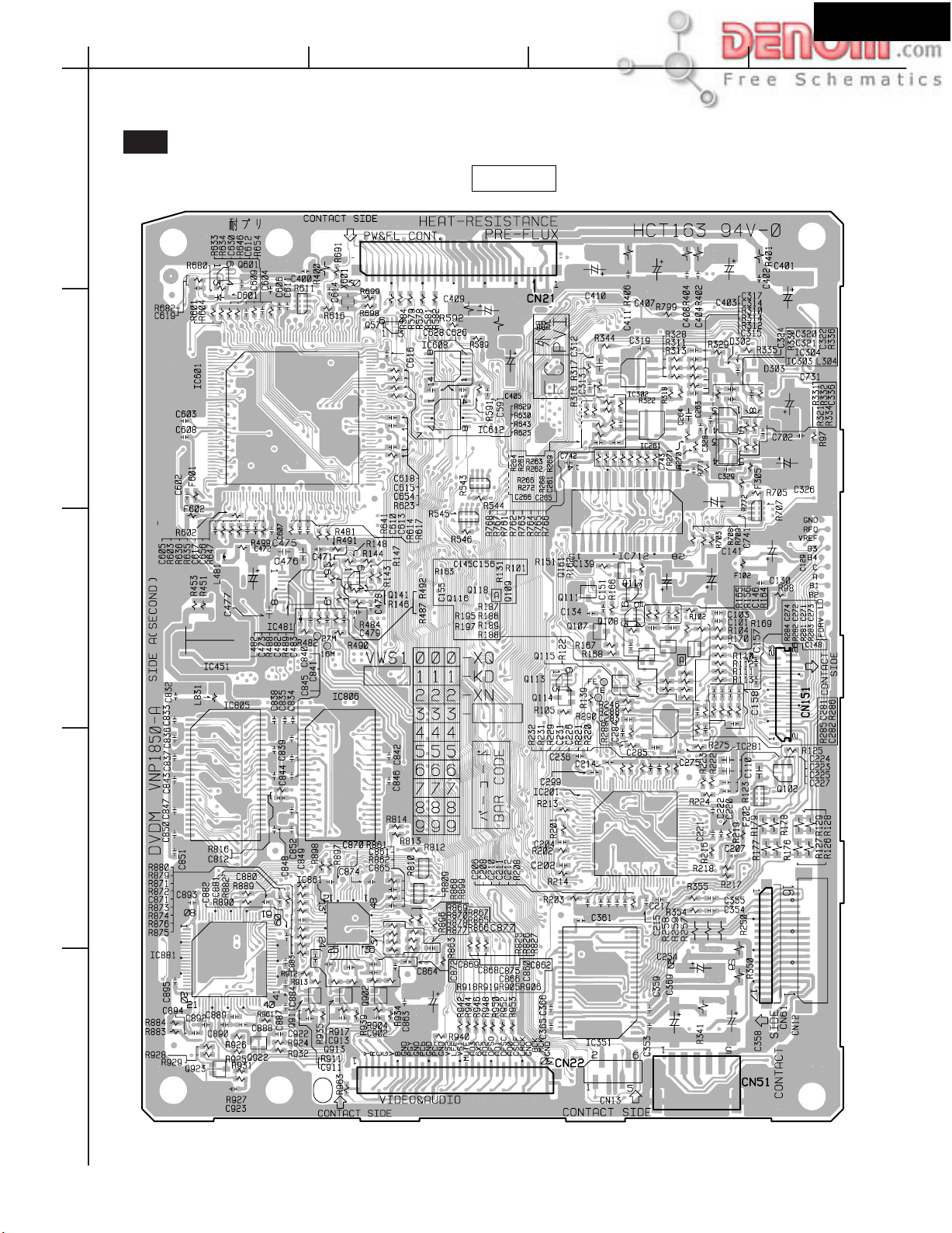
DSR-7.3
A
PRINTED CIRCUIT BOARD VIEWS-X
U16
DVD MAIN PC BOARD
1
2
UPP: DB-VPB314/XJ
EXCEPT UPP: DB-VPB313/XJ
IC601
BCD
SIDE A
IC601IC612
IC302
IC261
IC712
IC481
3
IC805
4
IC201
IC861
IC881
IC351
5
www.denom.com
Page 33

DSR-7.3
A
BCD
PRINTED CIRCUIT BOARD VIEWS-X2
U16
DVD MAIN PC BOARD
1
2
UPP: DB-VPB314/XJ
EXCEPT UPP: DB-VPB313/XJ
IC701
SIDE B
IC603
3
IC801
IC111
4
IC251
IC801
5
www.denom.com
Page 34

FL TUBE VIEW
Q7002: HNV-12SS12T
DSR-7.3
SVCDVD
Dp
11G
col
12G
TIMER
TITLE
DIGITAL PROLOGIC DSP LAST MUTING
AAC RPT CHP TRACK STEREO SLEEP REMAIN FM STEREO AUTO
9G 8G 7G 6G 5G
col
4G 3G
abcdefg
hjkmnpr
RDS
1G2G10G
dB
kHz
MHz
Dp
12G 11G 10 9G 8G 7G 6G 5G 4G 3G 2G 1G
P1 aaaaaaaaaa
P2
P3
P4
P5
P6
P7
P8
P9
S
V
C
D
VD
TIMER
TITLE
P10
P11
P12
DIGITAL
AAC
P13
P14
P15 - - - - - -
RPT
CHP
TRACK
PROLOGIC
STEREO
DSP
SLEEP
LAST
REMAIN
MUTING
FM STEREO
RDS
AUTO
m
j
m
j
j
j
j
j
j
j
j
h
h
h
h
h
h
h
h
h
k
k
k
k
k
k
k
k
k
b
b
b
b
b
b
b
b
b
f
f
f
f
f
f
f
f
f
g
g
g
g
g
g
g
g
g
m
m
m
m
m
m
m
m
c
c
c
c
c
c
c
c
c
e
e
e
e
e
e
e
e
e
n
n
n
n
n
n
n
n
n
r
r
r
r
r
r
r
r
r
p
p
p
p
p
p
p
p
p
d
d
d
d
d
d
d
d
d
Col
Dp
Dp
j
h
k
b
f
g
c
e
n
r
p
d
P16 - - - - - - - - - -
Col
P17 - - - - - - - - - - P18 - - - - - - - - - - -
www.denom.com
dB
kHz
MHz
Page 35

MICROPROCESSOR CONNECTION DIAGRAM
DSR-7.3
Q8001: MPD784225GC-XXX-8BT
MAIN POWER
TRANSFORMER
6ch volume with
8ch input selector
BD3811K1
Q3001
57
Front
To power
amp. section
Lch
Front
Rch
TUNER UNIT
CSN 19
CDTO 16
INT1 15
INT0 14
Q8201
6ch CODEC with DIR
AK4586
PDN 44
IR IN
P8712
46
47
48
Q3111
Q3112
Q8671
h
g
f
e
d
c
b
a
RESET
Q8003
T9001
MUTING
Q3116
41
42
43
44
45
46
47
48
49
50
51
52
53
54
55
56
57
58
59
60
POWER FAILURE
DETECTOR
+13V
AC IN
RL9001
40393837363534333231302928272625242322
STEREO
PLLSDO
PLLCLK
PLLCE
NU
NU
DIRCS
DSPSDI
DIRINT1
DIRINT0
INTREQ/ABOOT
DSPCS
ROM/RAM
ADDR15
ADDR16
ADDR17
DSPCLK
DSPSDO
DSPRST
DIRPD
RESET
POFF
61626364656667686970717273747576777879
+5V
Q9001
TUMUT
SD
RDSCLK
RDSDATA
FRONT
SPEAKER
Q5803
POWERL
AMUT
Q5801
SPACS
SPAFR
SELMUT
VSS1
RL5801
SWPRL
SELSDO
SELSCLK
Q5802
NU
NU
MICROPROCESSOR
(Audio control)
Q8001
MPD784225GC-XXX-8BT
NU: No use
RDSSIG
XLT
IRIN2
VSS0
VDD1X2X1
TEST
XY2
XT1
+5V
HPIN
VDD0
AVDD
+5V
CENTER
SPEAKER
RL5802
SURROUND
SPEAKER
RL5803
NU
NU
TPRT
VPRT
MCCLK/FPCLK
MCSDO/FLSO
MCSDI/FPSI
MCRDY/FPHS
DVDPOWER
SHOP MD
BAND
DVDBAND
IPM
Q8023
Buffer
21
NU
SYSIN
MCRST
XREADY
XSCLK
XSO
XSI
XRESET
NU
XS1
AVREF
AVSS
MODE4
MODE3
TRAYIN
MODE1
MODE2
80
INITIALIZING
INITIALIZING
20
19
18
17
16
15
14
13
12
11
10
9
8
7
6
5
4
3
2
1
+B
+5V
INITIALIZING
INITIALIZING
Detection switch
PHONES
P5901
Over current detection
Q5001
Q5802
Q5803
Thermal detection
Q8851
FRONT Lch
Other channel
DC voltage detection
FRONT Lch
Other channel
Thermistor
R8851
MICROPROCESSOR
(Display control)
Q7002
6 RESET
7 SUBCK
8 SUBSI
9 SUBSO
10 SUBREQ
MPD784225GC
-070-8BT
Regulater
Q9510
Q9511
Q9507
Q9502
Q9503
+3.3V
RI
P8711
CN21
+2.5V
+5V
DVD MAIN BOARD
+12V
CS 18
SCDIO 19
ABOOT 20
Audio Decoder
CS493292-CL
Q8101
SCLK 7
A1 SCDIN 6
abcdefgh
Buffer
TC74VHC541FT
Q8307
6 A17
10 A16
11 A15
30 CE
CMOS EPROM
MX27L2000TC-12
Q8611
RESET 36
www.denom.com
Audio signal detection
for IPM
Q3201
INITIALIZING
(Setting of destination )
INITIALIZING
(Setting of FM/AM Band)
TV IN
+6V
Video
circuit
Detection switch
of tray open
DVD MECHANISM
(TRAY LOADING UNIT)
Page 36

MICROPROCESSOR TERMINAL DESCRIPTION-1
Q8001: MPD784225GC-XXX-8BT
I/OPIN NAMENO. DESCRIPTIONACTIVE
DSR-7.3
TRAYIN
1
MODE3
2
MODE4
3
AVSS
4
SHOPMD
5
DVDPOWER
6
AVREF1
7
NU
8
NU
9
XRESET
10
XSI
11
XSO
12
XSCLK
13
XREADY
14
MCRDY/FPHS
15
MCSD/FPSI
16
MCSDO/FLSO
17
MCCLK/FPCLK
18
MCRST
19
SYSIN
20
I
A/D
I
A/D
I
A/D
I
O
O
O
O
I
O
O
I
I
O
O
O
I
H
H
H
H
H
CLK
H
H
H
H
CLK
L
H
Input pin of detected signal of tray state.
Input pin of initial setting.
Ground pin of A/D converter.
No used (Connect to ground)
Initial setting demonstration mode. H=shop mode.
Output pin of control signal for power supply of DVD main circuit.
Input pin of reference voltage or D/A converter.
No used.
No used.
Output pin of reset signal to microprocessor in DVD main board.
Output pin of serial data from microprocessor in DVD main board.
Output pin of serial data to microprocessor in DVD main board.
Output pin of clock signal to microprocessor in DVD main board.
Output pin of communication for microprocessor in DVD main board.
Input pin of ready data from Sub-microprocessor.
Input pin of data from sub-microprocessor.
Output pin of data to sub-microprocessor.
Output pin of serial clock to sub-microprocessor.
Output pin of reset signal for Sub-microprocessor.
Input pin of RI (system control signal).
21
22
23
24
25
26
27
28
29
30
31
32
33
34
35
36
37
38
39
40
NU
NU
SYSOUT
TPRT
VPRT
HPIN
NU
NU
PRL
SELSDO
SELSCLK
SELMUT
VSS1
SPACS
SPAFR
POWERL
AMUT
TUMUT
SD
STEREO
O
No used.
O
O
I
I
I
O
O
O
O
O
O
O
O
O
O
O
I
I
L
L
H
H
H
H
H
H
CLK
H
H
H
H
H
H
H
L
L
No used.
Output pin RI (System control).
Input pin of signal from thermal detection circuit.
Input pin of DC voltage detection signal from power amplifier.
Input pin of detection signal from insert state of headphone plug.
No used.
No used.
No use.
Output pin of serial data latch for BD3811 (volume and selector control IC).
Output pin of serial data clock for BD3811 (volume and selector control IC).
Output pin of muting signal for BD3811 (volume and selector control IC).
Ground pin.
Output pin of control signal for center speaker relay and surround speaker relay drive.
Output pin of control signal for front speaker relay drive.
Output spin of control signal for main power relay drive.
Output pin of control signal for audio muting circuit.
Output pin of control signal for of tuner muting circuit.
Input signal of detection signal of receiving state of broadcast.
Input pin of detection signal of FM stereo pilot signal.
www.denom.com
Page 37

MICROPROCESSOR TERMINAL DESCRIPTION-2
Q8001: MPD784225GC-XXX-8BT
I/OPIN NAMENO. DESCRIPTIONACTIVE
DSR-7.3
PLLSDO
41
PLLCLK
42
PLLCE
43
NU
44
NU
45
DIRCS
46
DSPSDI
47
DIRINT1
48
DIRINT0
49
INTREQ/ABOOT
50
DSPCS
51
ROM/RAM
52
ADDR15
53
ADDR16
54
ADDR17
55
DSPCLK
56
DSPSDO
57
DSPRST
58
DIRPD
59
RESET
60
POFF
61
RDSCLK
62
RDSDATA
63
RDSSIG
64
XLT
65
IRIN2
66
VSS0
67
VDD1
68
X2
69
X1
70
TEST
71
XT2
72
XT1
73
VDD0
74
AVDD
75
BAND
76
DVDBAND
77
IPM
78
MODE1
79
MODE2
80
O
O
O
O
I/O
O
O
O
O
O
O
O
O
O
H
CLK
H
-
-
I
I
I
-
I
I
I
I
I
I
-
-
-
-
-
-
-
-
I
I
I
I
I
-
L
H
H
H
H
L
H/L
H
H
H
H
H
L
L
-
L
CLK
H
H
H
L
-
-
-
-
-
-
-
-
-
A/D
A/D
A/D
A/D
A/D
Output pin of serial data for PLL IC of tuner unit.
Output pin of serial clock for PLL IC of tuner unit.
Output pin of serial latch for PLL IC of tuner unit.
No used.
No used.
Output pin of chip select signal to AK4586.
Input pin of serial data from CS493292 and AK4586.
Input pin of detection signal from function status of AK4586.
Input pin of interrupt request detection signal from function status of AK4586.
Input/output pin of signal from interrupt request and auto boot of CS493292
Output pin of signal for chip select.
Output pin of signal for select ROM or RAM.
Output pin of signal for select of DSP boot ROM address 15
Output pin of signal for select of DSP boot ROM address 16
Output pin of signal for select of DSP boot ROM address 17
Output pin of serial clock to CS493292 and AK4586.
Output pin of serial data to CS493292 and AK4586.
Output pin of reset signal to CS493292.
Output pin of power down signal to AK4586.
Input pin for system reset.
Input pin of power failure detected signal.
No used by DSR-7.3.
No used by DSR-7.3.
No used by DSR-7.3.
Input pin of latch signal from DVD main microprocessor.
Input pin of external control signal.
Ground pin.
Power supply pin.
Connect to ceramic oscillator.
Connect to ceramic oscillator.
No used.
No used. (open)
No used. (open)
Power supply pin.
Power supply pin for A/D converter.
Input pin for initial setting of destination (tuner band).
Input pin for initial setting of destination (DVD region cord).
Input pin for IPM (intelligent power management) function.
Input pin of initial setting.
Input pin of initial setting.
www.denom.com
Page 38

UPGRADE FIRMWARE-1
Prepares for upgrade firmware
DSR-7.3
REMOTE CONTROLLER
RC-484M
Part No. 24140484
Required to carry out check firmware
vertion and regeon cord.
INTERFACE JIG
Part No. GGF1348
Monitor TV
Required to carry out check firmware
vertion and regeon cord.
INTERFACE JIG (KIT)
Part No. 0J13
or
RS-232C Cable (Straight type Cable)
When using GGF1348
D-Sub 25pin
(Female type)
Flexible flat cable
Part No.:GGD1231 or 0F001
Video cable
D-Sub 9pin
(Male type)
D-Sub 9pin
(Female type)
or
PC (Personal computer)
When using 0J13
D-Sub 9pin
(Male type)
www.denom.com
Page 39

UPGRADE FIRMWARE-2
Connections
Rear panel view
DSR-7.3
Monitor TV
PC
(Personal computer)
PREOUT
AUDIO
IN IN
SUB
WOOFER
TV/LINE
DIGITAL
OPTICAL
OUT
IN
To monitor out
To Video in
L
IR
REMOTE
IN
CONTROL
R
OUT
MD/CDR/TAPE
VIDEO OUTPUT
YP
S VIDEO VIDEO COMPONENT
ANTENNA
BPR
ANTENNA
AM
Flexible flat cable
INTERFACE JIG
Part No.GGF1348
SURROUND
SPEAKERS
R
FM
75
L
FRONT SPEAKERS
CENTER
L
R
Connect to
CN1
AC INLET
INTERFACE JIG
Part No.0J13
OR
Connect to
25P
CN2
9P
RS-232C Cable
To PC
Prepare the file required for rewriting of the firmware.
Build the folder to C drive of the hard disk of PC,
and put in the file required for the folder.
The required file
NOTE: This is one example.
1. ok_down.exe
Rewriting tools
2. down.bat
Rewriting tools
3. b1bk1128.sz0
Firmware program
The file name changes with versions of the firmware.
Explorer view of PC
dsr73fw
dsr73fw
dsr73fw
b1bk1138.sz0
www.denom.com
Page 40

UPGRADE FIRMWARE-3
Flow chart
DSR-7.3
In the case of upgrade firmware
1
Check the firmware
When the firmware
is the newest version
2
Upgade firmware
3
Setting the regional code
Except UDD1N type
When the firmware
is not the newest version
In the case of replace of the DVD main board
Replace of the DVD main board
3
Setting the regional code
Except UDD1N type
1
Check the firmware
When the firmware
is not the newest version
When the firmware
is the newest version
Check the firmware and regional code
4
5
Check of general operation
www.denom.com
Page 41

UPGRADE FIRMWARE-4
1
Check the firmware
Please operate it by remote controller (RC-484M).
DSR-7.3
1. Press the DVD.
2. Power ON the unit by press ON.
3. Press the PLAY.
4. Press SETUP.
5. Operate cursor button and select General menu.
Refer to
6. Operate cursor button and select Setup Menu mode.
Refer to
Refer to
7. Operate cursor button and set as the state of Basic.
Refer to
Refer to
8. Press DISPLAY.
9. Check the Region cord and the firmware vertion.
Refer to
Refer to
10. Press the DISPLAY.
A
A
B
A
C
A
D
E
2
1
5
6
7
4
3
8
B
TV monitor
D
1
A
C
1.138
E
www.denom.com
Page 42

UPGRADE FIRMWARE-5
2
Upgrade firmware
[NOTES]
This procedure document supposing using Japanese PC.
The program file name, the folder name, etc. are examples.
1. Start MS-DOS prompt using the start-up menu of PC.
Windows of MS DOS prompt
DSR-7.3
dsr73fw
dsr73fw>down
C: WINDOWS>_
2. Press the
cd..
C: >_
3. Press the
cd dsr73fw
Space
dsr73fw
Enter
by the keyboard.
: The folder name which saves the program file
C: drl50fw>_
4. Press the
down b1bk1138.sz0
b1bk1138.sz0
Space
Enter
: The program fail name
The file name changes with firmware version.
Enter
by the keyboard.
button, after inputting
button, after inputting
Zero
button, after inputting
by the keyboard.
[The meaning of this sentence]
Please switch on the power supply after connecting
the DVD player and PC.
www.denom.com
Page 43

UPGRADE FIRMWARE-6
Download procedures
5. Check that the connection of PC with Unit.
7. Turn ON the power supply switch of the unit.
6. Check that unit is in the state of NO DISC.
8. Press the Enter key of PC.
9. Press the Enter button, after inputting MO by the keyboard of PC.
DSR-7.3
10. Press ENTER button, after inputting SZL by the keyboard of PC.
The file(b1bk1138.sz0) specified by the
command line is used in this program.
The program is checking the circuit.
The program starts transmission of the data to unit.
FL Display
ROM ERASE LOADING
www.denom.com
Page 44
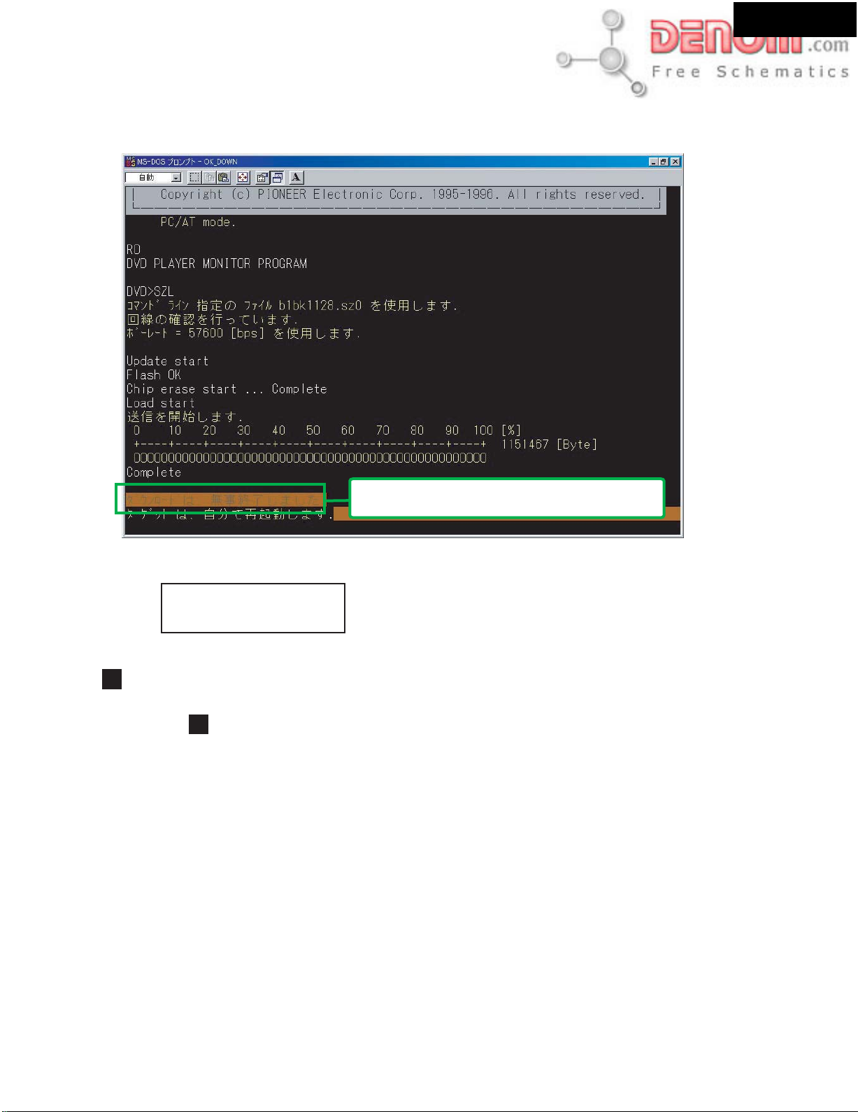
UPGRADE FIRMWARE-7
Download procedures
State witch download completed
The state which download completed
DSR-7.3
The work of download was completed satisfactory.
FL Display
NO DISC
4
Chack firmware and regional cord
You check whether it is set up firmware and repional cord correctly.
Refer to about check procedure.
1
www.denom.com
Page 45

P A CKING VIEW
DSR-7.3
A901
A912
A911
A411
P9001
A902
A913
A405
A407
A411
A407
A940
A931
A507
A407
A417
nt
o
Fr
Left
ont
Fr
Left
Left
Zone 2
/
Left
Zone 2
/
SP-B
ont
Fr
SP-B
Right
ont
Fr
Right
Zone 2
/
Right
ont
Fr
Zone 2
/
SP-B
Left
Right
ont
Zone 2
/
Fr
ound
Left
SP-B
Left
nd
Zone 2
/
SP-B
u
Surr
o
Left
Left
SP-B
eft
Surr
L
ound
ont
Right
1
Fr
Surr
ound
Right
ont
Right
Zone 2
/
Fr
Surr
Right
Zone 2
/
SP-B
Center
Right
S
p
ea
k
er Cab
l
e
k
SP-B
ight
Center
R
rround
k
Left
u
S
Left
ound Bac
2
Left
2
Surround
Surr
ound
ne
Left
ound Bac
o
Left
Z
Surr
Surr
ound
Left
Right
Zone 2
Surr
Right
k
ound Bac
Center
k
Surr
ound
Center
ound Bac
Surr
3
Surr
ound Bac
Left
Surr
Left
k
Zone 2
Left
k
Zone 2
Left
Surround Bac
ound Bac
Right
Surr
Right
Zone 2
Right
Zone 2
Right
Note
Insert to Page1
Note
Turn Tthe button side upward.
A921
k
k
Right
Bac
Right
Zone 2
Right
Zone 2
Right
A5031
A409
A401
Note
Piles up two pieces.
A5031
A401
A419
A401
A401
Note
Piles up two pieces.
A501
www.denom.com
A419
Page 46

DSR-7.3
Integra Division of
ONKYO CORPORATION
Sales & Product Planning Div. : 2-1, Nisshin-cho, Neyagawa-shi, OSAKA 572-8540, JAPAN
Tel: 072-831-8111 Fax: 072-833-5222 http://www.onkyo.co.jp/
Integra Division of
ONKYO U.S.A. CORPORATION
18 Park Way, Upper Saddle River, N.J. 07458, U.S.A.
Tel: 201-785-2600 Fax: 201-785-2650 E-mail: integra@onkyousa.com http://www.integrahometheater.com
ONKYO EUROPE ELECTRONICS GmbH
Industriestrasse 20, 82110 Germering, GERMANY
Tel: 089-849-320 Fax: 089-849-3265 E-mail: info@onkyo.de
ONKYO CHINA LIMITED
Units 2102-2107, Metroplaza Tower I, 223 Hing Fong Road, Kwai Chung,
N.T., HONG KONG Tel: 852-2429-3118 Fax: 852-2428-9039
www.denom.com
 Loading...