

Ingersoll-Rand 302 SERIES Installation And Operation Manual

INGERSOLL RAND
302 SERIES
VARIABLE FREQUENCY DRIVE
INSTALLATION AND OPERATION MANUAL
More Than Air. Answers.
Online answers: http://www.air.irco.com
Before installing or starting this unit for the first time, this
manual should be studied carefully to obtain a working
knowledge of the unit and/or the duties to be performed
while operating and maintaining the unit.
RETAIN THIS MANUAL WITH UNIT. This Technical
manual contains IMPORTANT SAFETY D ATA and
should be kept with the unit at all times.
C.C.N. : 23046360
REV. C
DATE: DECEMBER 2009

2
TABLE OF CONTENTS
TABLE OF CONTENTS ................................................... 2
SECTION 1 — INTRODUCTION ..................................... 3
SECTION 2 — SAFETY .................................................. 3
SAFETY PRECAUTIONS ....................................................... 3
SHIPMENT INSPECTION / PRE-INSTALLATION CHECK ............... 3
LIFTING .......................................................................... 3
INSTALLATION ................................................................. 3
MECHANICAL INSTALLATION .............................................. 3
OPERATION .................................................................... 4
MAINTENANCE AND REPAIR .............................................. 4
INGERSOLL RAND 302 SERIES VFD WARNINGS AND
PRECAUTIONS ................................................................. 4
WARNING AGAINST UNINTENDED START ............................. 5
SECTION 3 — CONTROL FEATURES AND FUNCTIONS .. 6
STANDARD FEATURES AND FUNCTIONALITY .......................... 6
SECTION 4 — INSTALLATION ..................................... 10
SECTION 5 — DISPLAY AND MENU OPERATION ........ 18
SECTION 6 — COMMISSIONING ................................ 25
PHYSICAL CHECKS .......................................................... 25
RESISTANCE CHECKS ....................................................... 25
KEYPAD OPERATIONS ..................................................... 25
POWER-UP CHECKS ....................................................... 25
INTELLISYS SETUP ........................................................... 25
SECTION 7 — FAULT CODES ...................................... 31
WARNINGS / ALARM MESSAGES ...................................... 31
SECTION 8 — PART LIST ............................................ 39
SECTION 9 — TECHNICAL DATA ................................. 40
SECTION 10 — WIRING DIAGRAM ............................. 46
Refer to Section Indicated
Note
Important or Caution, Safety
3
SECTION 1 — INTRODUCTION
The purpose of this manual is to provide instructions
needed to install, operate, and maintain the IngersollRand rotary screw air compressor with the Ingersoll Rand
302 Series Variable Frequency Drive (VFD). The
Operators/Instruction Manual supplied with the
compressor and this Instruction Manual supplied with the
Ingersoll Rand 302 Series VFD should be referenced for
more detailed instructions regarding each of these
components.
The Ingersoll Rand 302 Series VFD will maintain a
constant pressure in compressed air systems by
adjusting the compressor motor’s speed to match the
compressed air usage. Depending on the application and
air demand profile, the Ingersoll Rand 302 Series VFD
system can achieve 25-35% energy savings. Smooth
start-up, reduced machine cyc l ing, lower noise, and
monitoring energy parameters are other benefits from an
Ingersoll-Rand compressor equipped with Ingersoll Rand
302 Series VFD.
SECTION 2 — SAFETY
SAFETY PRECAUTIONS
WARNING: Risk of Danger
WARNING: Risk of Electric Shock
WARNING: Risk of High Pressure
WARNING: Consult Manual
• Before installing or operating the Ingersoll Rand
302 Series VFD, take time to carefully read all
the instructions contained in this manual, all
compressor manuals, and all manuals of any
other peripheral devices that may be installed or
connected to the unit.
• Electricity and compressed air have the
potential to cause severe personal injury or
property damage.
• The operator should use common sense and
good working practices while operating and
maintaining this system. All applicable codes
should be strictly adhered to.
• Maintenance must be performed by adequately
qualified personnel that are equipped with the
proper tools.
SHIPMENT INSPECTION / PREINSTALLATION CHECK
• The crating should be inspected for shipping
damage after the unit has arrived.
• Before unpacking the frequency converter it is
recommended that it is located as close as
possible to the final installation site. Remove the
box and handle the frequency converter on the
pallet, as long as possible.
LIFTING
• Always lift the frequency converter in the
dedicated lifting eyes. Use a bar to avoid
bending the lifting holes of the frequency
converter.
INSTALLATION
• Installation work must only be carried out by a
competent person under qualified supervision.
• A fused isolation switch must be fitted between
the main power supply and the Ingersoll Rand
302 Series VFD.
• The Ingersoll Rand 302 Series VFD should be
mounted in such a location as to allow
operational and maintenance acces s without
obstruction or hazard and to allow clear visibility
of indicators at all times.
• If raised platforms are required to provide
access to the Ingersoll Rand 302 Series VFD,
they must not interfere with normal operation or
obstruct access. Platforms and stairs should be
of grid or plate construction with safety rails on
all open sides.
MECHANICAL INSTALLATION
• Preparation of the mechanical installation of the
frequency converter must be done carefully to
ensure a proper result and to avoid additional
work during installation. Start taking a close look
at the mechanical drawings at the end of this
instruction to become familiar with the space
demands.
• To perform the mechanical installation the
following tools are needed:
o Drill with 10 or 12 mm drill
o Tape measure
o Wrench with relevant metric sockets (7-17
mm)
o Extensions to wrench
o Sheet metal punch for conduits or cable
glands in IP 21/Nema 1 and IP 54 units
o Lifting bar to lift the unit (rod or tube max. Ø
25 mm (1 inch), able to lift minimum 400 kg
(880 lbs)).
o Crane or other lifting aid to place the
frequency converter in position
o A Torx T50 tool is needed to install the E1
in IP21 and IP54 enclosure types.

4
• Space: Ensure proper space above and below
the frequency converter to allow airflow and
cable access. In addition space in front of the
unit must be considered to enable opening of
the door of the panel.
• Wire access: Ensure that proper cable access is
present including necessary bending allowance.
As the IP00 enclosure is open to the bottom
cables must be fixed to the back panel of the
enclosure where the frequency converter is
mounted, i.e. by using cable clamps.
o All cable lugs/ shoes must mount within the
width of the terminal bus bar
OPERATION
• The Ingersoll Rand 302 Series VFD must onl y
be operated by competent personnel under
qualified supervision.
• Never remove or tamper with safety devices,
guards or insulation materials fitted to the
Ingersoll Rand 302 Series VFD.
• The Ingersoll Rand 302 Series VFD must onl y
be operated at the supply voltage and frequency
for which it is designed.
• When main power is switched on, lethal
voltages are present in the electrical circuits and
extreme caution must be exercised whenever it
is necessary to carry out any work on the unit.
• Do not open access panels or touch electrical
components while voltage is applied unless it is
necessary for measurements, tests or
adjustments. Such work should be carried out
only by a qualified electrician equipped with the
correct tools and wearing appropriate protection
against electrical hazards.
• All air compressors and/or other equipment
connected to the unit should have a warning
sign attached stating “THIS UNIT MAY START
WITHOUT WARNING” next to the display panel.
• If an air compressor and/or other equipment
connected to the unit is to be started remotely,
attach two warning signs to the equipment
stating “THIS UNIT CAN BE STARTED
REMOTELY”. Attach one sign in a prominent
location on the outside of the equipment, and
the other sign inside the equipment control
compartment.
MAINTENANCE AND REPAIR
• Maintenance, repairs or modifications must only
be carried out by competent personnel under
qualified supervision.
• If replacement parts are required, use only
genuine parts from the original equipment
manufacturer, or an alternative approved
source.
• Carry out the following operati ons before
opening or removing any access panels or
carrying out any work on the Ingersoll Rand 302
Series VFD:
i. Isolate the Ingersoll Rand 302 Series
VFD from the main electrical power
supply. Lock the isolator in the “OFF”
position and remove the fuses.
ii. Attach labels to the isolator switch and
to the unit stating “WORK IN
PROGRESS - DO NOT APPLY
VOLTAGE”. Do not switch on electrical
power or attempt to start the CX Box if
such a warning label is attached.
• Make sure that all instructions concerning
operation and maintenance are strictly followed
and that the complete unit, with all accessories
and safety devices, is kept in good working
order.
• The accuracy of sensor devices must be
checked on a regular basis. They must be
calibrated when acceptable tolerances are
exceeded. Always ensure any pressur e withi n
the compressed air system is safely vented to
atmosphere before attempting to remove or
install a sensor device.
• The Ingersoll Rand 302 Series VFD must onl y
be cleaned with a damp cloth, using mild
detergents if necessary. Avoid the use of any
substances containing corrosive acids or alkalis.
• Do not paint the control faceplate or obscure
any indicators, controls, instru ctio ns or
warnings
.
INGERSOLL RAND 302 SERIES VFD
WARNINGS AND PRECAUTIONS
• The frequency converter DC link capacitors
remain charged after power has been
disconnected. To avoid electrical shock hazard,
disconnect the frequency converter from the
mains before carrying out maintenance. Before
doing service on the frequency converter wait at
least the amount of time indicated below:
o 380 - 500 V 90 - 200 kW 20 minutes
250 - 800 kW 40 minutes
o 525 - 690 V 37 - 315 kW 20 minutes
355 - 1200 kW 30 minutes
• The Stop/Reset key on the local control panel of
the Ingersoll Rand 302 Series VFD DOES NOT
disconnect the equipment from the AC line. DO
NOT use the Stop/Reset key as a safety switch.
• The installer must supply correct protective
grounding of the equipment. The user must be
protected against supply voltage, and the motor
must be protected against ove rload in
accordance with National Electric Code and
local codes.
• To avoid potential shock hazard when servicing
a motor or Ingersoll Rand 302 Series VFD ,
remove all power to all drives with wiring that
shares any conduit to be worked on. If that is
not possible, remove power to the drive and
ground the motor wires at the drive. When the
work has been completed, remove the grounds
before reapplying power to the drive. In general,
a conduit should not contain unshielded power
conductors for more than three PWM operated
motors.
5
• The earth leakage current from the frequency
converter exceeds 3.5 mA. To ensure that the
earth cable has a good mechanical connection
to the earth connection (terminal 95), the cable
cross section must be at least 10 mm
2
or 2 rated
earth wires terminated separately.
• The Electronic Thermal Relay (ETR) in UL/cUL
listed VFDs provides class 20 motor overload
protection in accordance with the NEC in a
single motor applications when parameter 1-40
is set for "TRIP" and parameter 1-24 is set for
the nominal motor rated (nameplate) current.
Protection against motor overload is NOT
included in the factory setting. If this function is
desired, set parameter to 1-40 to data value
ETR trip or data value ETR warning.
ETR function is initialized at 1.16 x rated motor
current.
WARNING AGAINST UNINTENDED
START
• The motor can be brought to a stop by means of
digital commands, bus commands, references
or a local stop, while the Ingersoll Rand 302
Series VFD is connected to the AC line. These
stop functions are NOT sufficient to ensure that
no unintended start occurs and should NOT be
used for personal safety considerations.
• While parameters are being changed, the motor
may start. Consequently, the Stop/Reset button
must be enabled (Parameter 0-41) after which
data can be modified. When the drive is in local
stop the LCP will be flashing. Parameter 0-41
will be changed later during the startup
procedure.
• A motor that has been stopped may start if
faults occur in the electronics of the Ingersoll
Rand 302 Series VFD or if a temporary overload
or a fault in the AC line supply or the motor
connection clears.
WARNING: The Ingersoll Rand 302 Series VFD contains dangerous voltages when connected to line
voltage. After disconnecting from the line wait at least 15 minutes before touching any electrical components. Also make
sure that other voltage inputs have been disconnected, such as external 24 VDC, load-sharing (linkage of DC intermediate
circuit), as well as the motor connection for kinetic back-up. Only a competent electrician should carry out the electrical
installation. Improper installation of the motor or the Ingersoll Rand 302 Series VFD may cause equipment fail ur e, seri ous
injury or death. Follow this manual and National
WARNING: Electrostatic Discharge (ESD) Precaution. Many electronic components are sensitive to static
electricity. Voltages are so low that they cannot be felt, seen or heard, can reduce the life, affect performance, or completely
destroy sensitive electronic components. When performing service, proper ESD equipment should be used to prevent
possible damage from occurring.
WARNING: It is the responsibility of the user or the person installing the Ingersoll Rand 302 Series VFD to
provide proper grounding, as well as motor overload and branch circuit protection according to the National Electrical Code
and local codes.

6
SECTION 3 — CONTROL FEATURES AND FUNCTIONS
STANDARD FEATURES AND
FUNCTIONALITY
The Ingersoll Rand 302 drive is an external device that is
wired to the compressor’s motors through the starter
panel. The Intellisys controller on the compressor still
starts and stops the compressor, while the Ingersoll Rand
302 Series VFD’s controller varies the compressor’s
motor speed to regulate constant system pressure. The
Ingersoll Rand 302 Series VFD operates in two different
setups:
1) In Setup 1, the Ingersoll Rand 302 Series VFD runs at
constant minimum speed and the compressor is
unloaded.
2) In Setup 2, the Ingersoll Rand 302 Series VFD
regulates a constant pressure and the compressor is
loaded.
The Intellisys controller logic determines which setup the
Ingersoll Rand 302 Series VFD operates.
See Intellisys and Ingersoll Rand 302 Series VFD
Controllers Interface Logic Diagram
As always, the Intellisy s contr o ller, set to On / Off Line
mode, will load and unload the compressor, depending
on the system pressure relative to the pressure band
limits. The Ingersoll Rand 302 Series VFD, however, tries
to keep the system pressure within the pressure band as
long as possible.
When the system pressure rises above the target
pressure, the drive will slow the compressor’s motors so
that the compressor supplies less air to the system and
allows the pressure to fall. Likewise, when the system
pressure falls, the drive increases the compressor’s
motor speed so that the compressor supplies more air to
the system.
The compressor with the Ingersoll Rand 302 Series VFD
will only load and unload at minimu m spee d, unle ss the
system pressure swings outside the Intellisys pressure
band faster than the drive can react. When the system
pressure rises above the Off Line pressure setpoint, the
blowdown valve opens and the inlet valve closes to
unload the compressor. The load relay, 2CR,
simultaneously opens to switch the drive to Setup 1
(constant, minimum speed).
Conversely, when the system pressure falls below the On
Line pressure setpoint, the blowdown valve closes and
the inlet valve opens to load the compressor. The load
relay, 2CR, simultaneously closes to swit ch the drive to
Setup 2 (pressure regulation).
Even with the Ingersoll Rand 302 Series VFD wired to
the compressor, the Start button on the Intellisys
controller initiates the full-voltage or star-delta starters.
When the 1M contactor closes, the start relay, 1CR,
closes to start the Ingersoll Rand 302 Series VFD. On
air-cooled, SSR units, the contactors have no power
flowing through them. However, the 1M contactor does
provide power to the constant-speed fan (for a watercooled unit) and the oil pump (on Sierra units only). After
the Start process is completed, the compressor will
automatically load and the Ingersoll Rand 302 Series
VFD will try to regulate the pressure.
On SSR air cooled units, the Ingersoll Rand 302 Series
VFD controls the main drive motor and the cooling fan
motor.
On SSR water cooled units, the Ingersoll Rand 302
Series VFD controls the main drive motor. The small
enclosure fan motor gets its power from the compressor
starter.
On Sierra units, the air cooled and water cooled units are
configured the same as the SSR units, except the
externally driven oil pump gets its power from the
compressor starter.
7
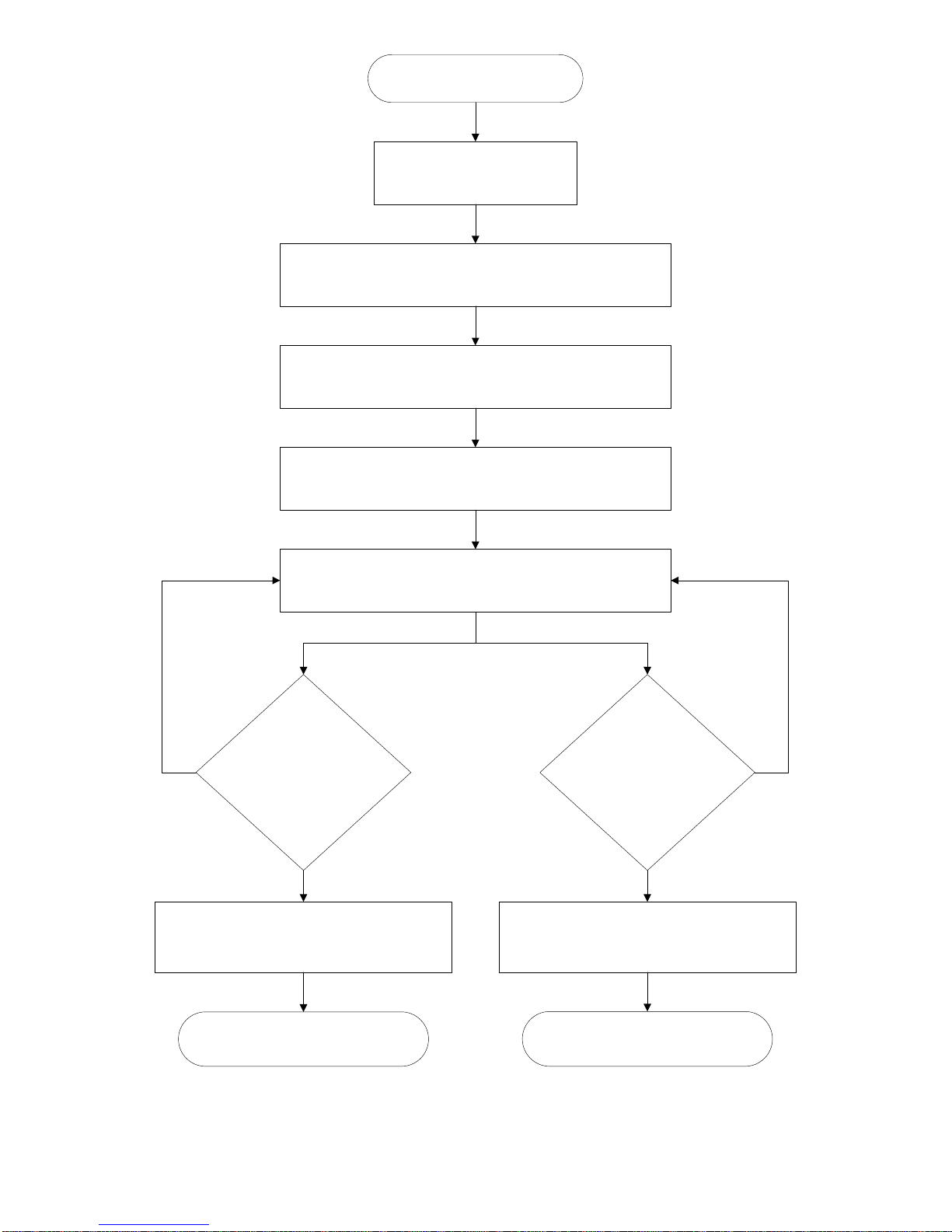
Power at VFD & Compressor
VFD Closes 3CR Relay
Press “START” on Compressor
The Intellisys Closes 1CR Relay to “START” the VFD. The
Compressor begins to run Unloaded with the VFD in SETUP 1
The Intellisys loads the Compressor and closes 2CR Relay
switching to SETUP 2. Variable Speed and Flow operation
continues until the Intellisys Unloads the Compressor.
The Intellisys Unloads the Compressor, opening 2CR Relay.
This switches the VFD to SETUP 1. The Compressor slows
down to minimum speed for the duration of the Unload cycle.
The Compressor continues to cycle between Load and Unload
(2CR Relay closing/opening) until one of the following
happens:
Has the Intellisys
decided the Unload time
has been long enough
to shut the
Compressor off?
Has the VFD Faulted
for any reason?
(I.E.: High Current,
Loss of Phase, etc.)
The Intellisys shuts down the Compressor and
Opens 1CR Relay, stopping the VFD power to
the motor.
The VFD Drive opens 3CR Relay telling the
Intellisys to Stop the Compressor immediately,
similar to the Compressor “Emergency Stop”
button being pressed.
The Compressor and the VFD are
stopped in “Stand-by” mode awaiting a
Start signal.
The Compressor and VFD Stop, both
flashing alarms.
INTELLISYS AND Ingersoll Rand 302 Series VFD CONTROLLERS INTERFACE LOGIC DIAGRAM
8
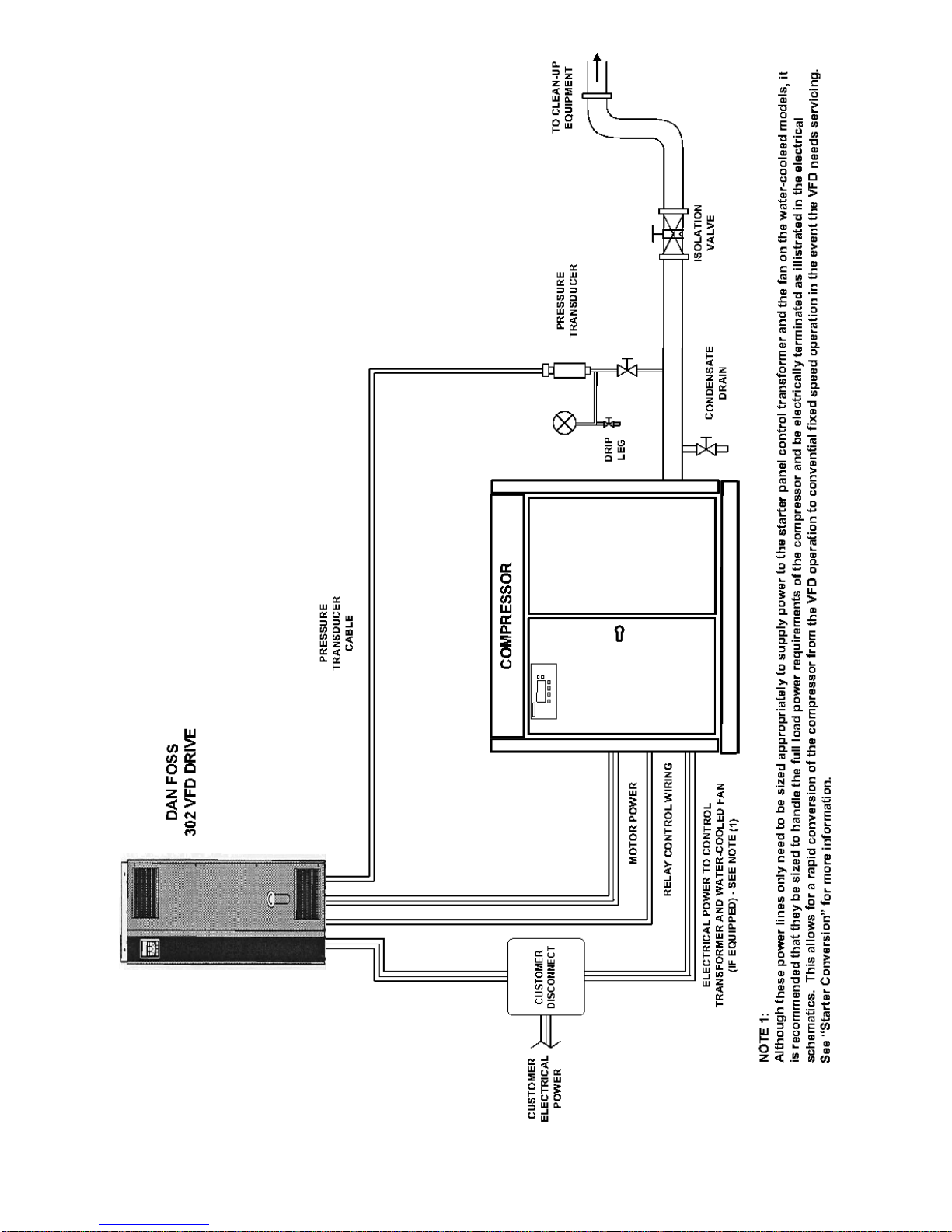
RECOMMENDED INGERSOLL RAND 302 SERIE S VFD AND COMPRESSOR SYSTEM INSTALLATION
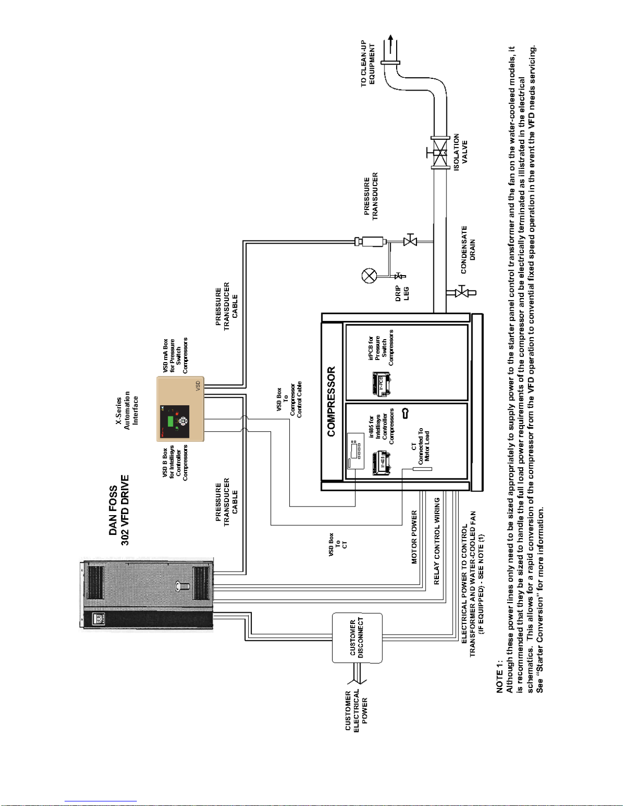
9
RECOMMENDED INGERSOLL RAND 302 SERIE S V FD AND COMPRESSOR SYSTEM INSTALLATION
WITH X-SERIES INTERFACE
10
SECTION 4 — INSTALLATION
When you receive the Ingersoll Rand 302 Series VFD,
inspect it closely. Any indication of careless handling by
the carrier should be noted on the delivery receipt,
especially if the Ingersoll Rand 302 Series VFD will not
be immediately uncrated. Obtaining the delivery person’s
signed agreement to any noted damages will facilitate
any future insurance c laims.
Uncrating and Handling
It is recommended that installation and
commissioning be carried out by an authorized and
trained product supplier.”
To lessen the possibility of damage, it is recommended
that the crated Ingersoll Ra nd 302 Series VFD be located
as close to the final installation site as possible. If the
Ingersoll Rand 302 Series VFD is not to be installed
immediately, the following storage temperatures need to
be observed: –13°F to +150°F (-25°C to +65°C).
Door and ceiling clearances must be considered when
moving and installing the drive.
A qualified person with a forklift or other similar lifting
device will be needed to remove the drive from the crate.
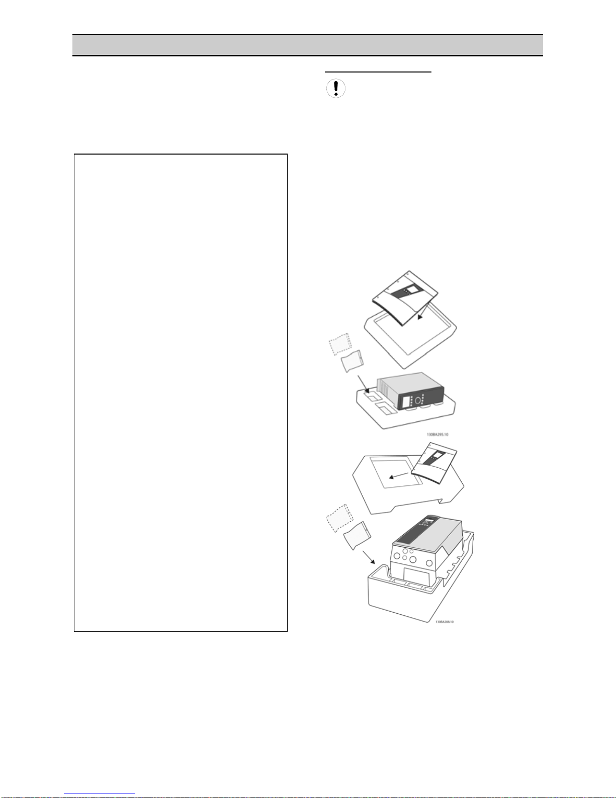
When unpacking the frequency converter, ensure that the
unit is undamaged and complete.
IMPORTANT
READ THIS
LOST OR DAMAGED GOODS
THOROUGHLY INSPECT THIS SHIPMENT
IMMEDIATELY UPON ARRIVAL
OUR RESPONSIBILITY FOR THIS SHIPMENT
CEASED WHEN THE CARRIER SIGNED
If goods are received short or in damaged condition,
it is important that you notify the carrier and insist on
a notation of the loss or damage across the face of
the freight bill. Otherwise no claim can be enforced
against the transportation company.
If concealed loss or damage is discovered, notify
your carrier at once and request an inspection. This
is absolutely necessary. Unless you do this the
carrier will not entertain any claim for loss or
damage. The agent will make an inspection and
grant a concealed damage notation. If you give the
transportation company a clear receipt for goods
that have been damaged or lost in transit, you do so
at your own risk and expense.
WE, AT INGERSOLL RAND, ARE WILLING TO
ASSIST YOU IN EVERY POSSIBLE MANNER TO
COLLECT CLAIMS FOR LOSS OR DAMAGE, BUT
THE WILLINGNESS ON OUR PART DOES NOT
MAKE US RESPONSIBLE FOR COLLECTION OF
CLAIMS OR REPLACEMENT OF MATERIAL. THE
ACTUAL FILING AND PROCESSING OF THE
CLAIM IS YOUR RESPONSIBILITY.
Ingersoll-Rand Company
Davidson, North Carolina
APDDG-99-79
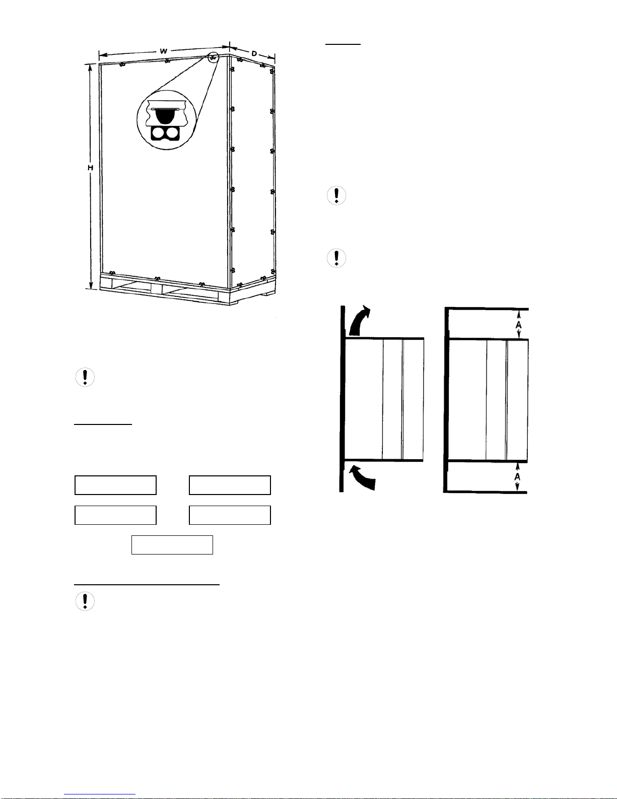
11
To open the crate: Pry up the metal locking tabs that
secure the top panel of the crate, this will allow access to
the lifting rings on the top of the drive.
See General Arrangement drawings in the VSD
Interconnect Guide for dimensions, weight, and
installation information.
Environment
The area selected for the location of the Ingersoll Rand
302 Series VFD should be free of dust, chemicals, metal
filings, paint fumes and overspray.
Dimensions: NEMA1 & NEMA 12
See General Arrangement drawings in the VSD
Interconnect Guide for dimensions, weight, and
installation information.
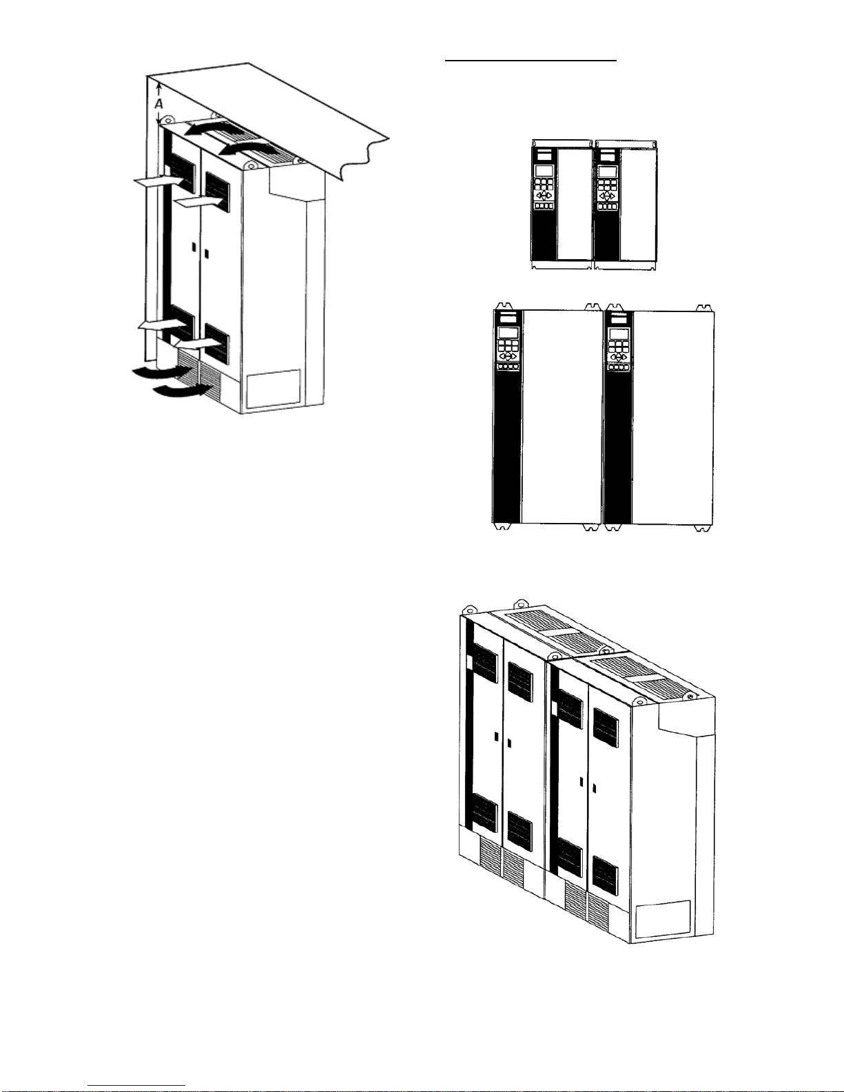
Cooling
The Ingersoll Rand 302 Ingersoll Rand 302 Series VFD is
cooled by means of air circulation. For the cooling air to
escape from the unit a minimum clearance must be left
above and below the unit.
The Ingersoll Rand 302 Ingersoll Rand 302 Series VFD
must be installed vertically.
To avoid overheating the unit, the ambient temperature is
not to exceed 115°F (46°C) and the mean temperature is
not to exceed 104°F (40°C). If the ambient temperature is
in the range of 115°F to 131°F (46°C to 55°C), there is a
possibility of a reduction of the service life of the Ingersoll
Rand 302 Series VFD .
For proper cooling, mount the Ingersoll Rand 302
Series VFD against a flat surface, such as a wall or a
piece of sheet metal.
Top and Bottom Free Space
See General Arrangement drawings in the VSD
Interconnect Guide for Air Space requirements.
DUST CHEMICALS
PAINT SPRAY
METAL FILINGS
OVERSPRAY
12
Side by Side Free Air Space
The Ingersoll Rand 302 Series VFD does not require free
air space between drives.
13
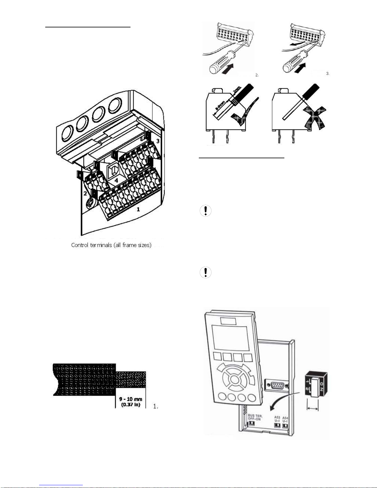
Terminal and Switch Locations
Control Terminals, Ingersoll Rand 302 Series VFD
Drawing reference numbers:
1. 10 pole plug digital I/O.
2. 3 pole plug RS485 Bus.
3. 6 pole analog I/O.
4. USB Connection.
To mount the cable to the terminal:
1. Strip insulation of 9-10 mm
2. Insert a screwdriver1) in the square hole.
3. Insert the cable in the adjacent circular hole.
4. Remove the screw driver. The cable is now
mounted to the terminal.
To remove the cable from the terminal:
1. Insert a screwdriver (1) in the square hole.
2. Pull out the cable.
(1)Max. 0.4 x 2.5 mm
.
Switches S201, S202, and S801
Switches S201 (A53) and S202 (A54) are used to select
a current (0-20 mA) or a voltage (-10 to 10 V)
configuration of the anal og inp ut termin als 53 and 54
respectively.
Switch S801 (BUS TER.) can be used to enable
termination on the RS-485 port (terminals 68 and 69).
See Power Wiring Diagram in the VSD
Interconnect Guide for all electrical terminals.
Default setting:
• S201 (A53) = OFF (voltage input)
• S202 (A54) = OFF (voltage input)
• S801 (Bus termination) = OFF
When changing the function of S201, S202 or
S801 be careful not to use force for the switch over. It is
recommended to remove the LCP fixture (cradle) when
operating the switches. The switches must not be
operated with power on the frequency converter.

14
Ingersoll Rand 302 Series VFD Electrical
Installation
The voltage of the Ingersoll Rand 302 Series VFD is
dangerous when the unit is connected to the AC line.
Incorrect installation of the motor or Ingersoll Rand 302
Ingersoll Rand 302 Series VFD may lead to material
damage or serious injury or death. Follow the instructions
in this manual and comply to National El ectr ica l Codes
(NEC) and local codes and safety guidelines.
DO NOT touch the electrical components of the
Ingersoll Rand 302 Series VFD for at least 15 minutes
after the AC line has been disconnected.
To avoid potential shock hazard when servicing a motor
or variable frequency drives, remove all power to all
drives having wiring that shares any conduit to be worked
on. If that is not possible, remove power to the drive and
ground the motor wires at the drive. When the work has
been completed, remove the grounds before reapplying
power to the drive.
In general, a conduit should not contain unshielded
power conductors for more than three PWM operated
motors.
It is the responsibility of the user or installer to
ensure correct grounding, branch circuit and motor
protection in accordance with the NEC and local codes
Connection of AC Line
Connect the three AC line phases to L1 (91), L2 (92), and
L3 (93) of the terminal block labeled Mains.
See Power Wiring Diagrams in the VSD
Interconnect Guide
To minimize electrical noise, install the drive within
100 feet (30 meters) of compressor.
To avoid electrical noise, do not route high-voltage
motor wires and low-voltage control wires through the
same conduit.
For proper safety, wire compressor and drive to a
common ground.
Schematics
The following table lists the electrical schematics that
illustrate the proper way to wire the Ingersoll Rand 302
Series VFD to the compressor. Locate t he corr e ct
schematic for the corresponding compressor and refer to
the Wiring Schematics section in this manual. The three
control relays, pressure transd ucer, and con tac t or (Si erra
only) should be wired per the proper schematic.
See Compressor Schematics in the VSD
Interconnect Guide
Safety Grounding
Please note that the Inger s oll Rand 302 Series VFD has
a high leakage current and must be grounded
appropriately for safety reasons. Use the ground
terminals (refer to the terminal drawings) which enable
reinforced grounding.
All national and local safety codes must be
observed.
See Power Wiring Diagrams in the VSD
Interconnect Guide
Motor Connection
The power cables from the Ingersoll Rand 302 Series
VFD connect to the motor terminal block located at the
bottom of the compressor’s starter box. The compressor
and fan motors’ leads are connected to the other side of
this block.
The power cables from the compressor/Ingersoll Rand
302 Series VFD system’s main disconnect (DIS1) to the
top of the compressor’s starter contactors sho uld be
sized for the full amp rating of the machine. This setup
allows for the compressor to be quickly converted from
variable speed to constant speed control should the
Ingersoll Rand 302 Series VFD need servicing.
See Power Wiring Diagrams in the VSD
Interconnect Guide
 Loading...