

Page 1
OPERATING MANUAL
MicroFID
Flame Ionization Detector
IPN 074-579-P1A
™
II
Page 2

Warning: Limitation of Liability
The ultimate responsibility of the consequences of use of toxic compounds rests with the user. INFICON’s
role is as a supplier of instrumentation to assist in the early detection of hazardous conditions involving
such compounds.
It is vitally important to ensure that the MicroFID II is maintained in accordance with INFICON’s
instructions and that proper calibration is regularly performed.
MicroFID II service should be performed only by INFICON, Inc., or an authorized INFICON repair center.
Unauthorized service may void the Intrinsic Safety Certifications.
As with any complex device, the MicroFID II is subject to failure and, while INFICON has taken, and
continues to take, all possible precautions to (a) reduce the possibility of failure, and (b) warn the user in
the event of failure, circumstances may occasionally occur in which there is a failure despite such
precautions on INFICON’s part. INFICON regrets that it cannot accept liability for damages of any kind
caused as a result of either failure of the user to follow instructions or of the MicroFID II to perform.
074-579-P1A 2
Page 3

Part Number
Release
Publication Date
MN201103
A
6 September 2011
074-579-P1
A
16 October 2012
Release History
Customer Service
INFICON
Two Technology Place
East Syracuse, NY 13057 USA
315-434-1100
www.inficon.com
Notices
The information contained in this document is subject to change without notice. INFICON makes no
warranty of any kind with regard to the material, including, but not limited to, the implied warranties of
merchantability and fitness for a particular purpose.
INFICON shall not be liable for errors contained herein for incidental or consequential damages in
connection with furnishing, performance or use of this material.
Copyright © 2012 by INFICON
MicroFID IITM is a Trademark of INFICON
Windows® is a Registered Trademark of Microsoft Corporation
Bluetooth® is a registered Trademark of Bluetooth SIG, Inc.
Tedlar® and Teflon® are Registered Trademarks of E.I. du Pont de Nemours & Company, Inc.
A component of this device is licensed under U.S. Patent No. 7,369,945 B2
074-579-P1A 3
Page 4

Table of Contents
FOR YOUR SAFETY ............................................................................................................................ 7
NOTICES AND WARNINGS .............................................................................................................. 8
FCC Warning ............................................................................................................................................... 8
MicroFID II Intrinsic Safety Notice ............................................................................................................. 8
DECLARATION OF CONFORMITY ........................................................................................................... 11
1. INTRODUCTION ............................................................................................................................. 13
About this Manual ..................................................................................................................................... 13
UNPACKING THE MicroFID II ................................................................................................................... 14
WARNINGS AND SAFETY PRACTICES .................................................................................................. 14
Excessive Heat and Cold ........................................................................................................................ 14
Flame Ionization Detector Operation ...................................................................................................... 15
Detector Response ................................................................................................................................. 16
Support Equipment and Consumables ................................................................................................... 16
Compressed Gases ................................................................................................................................ 16
Regulators for Compressed Gases ......................................................................................................... 17
Hydrogen Gas ......................................................................................................................................... 17
Calibration Gas ....................................................................................................................................... 18
Oxygen Concentration Limits .................................................................................................................. 18
Flammable Gases ................................................................................................................................... 18
ACCESSORIES .......................................................................................................................................... 19
Computer ................................................................................................................................................. 19
Gas Sampling Bag .................................................................................................................................. 19
Charcoal Filters ....................................................................................................................................... 19
2. USING THE MICROFID II ............................................................................................................. 21
MicroFID II Feature Layout ....................................................................................................................... 21
Filling the Hydrogen Fuel Cylinder ......................................................................................................... 25
Attaching the Telescoping Probe to the MicroFID II ............................................................................. 33
Basic Operating Instructions ................................................................................................................... 33
Calibration.................................................................................................................................................. 34
Data Communication ................................................................................................................................ 34
Response Factors for Gases and Vapors ............................................................................................... 34
To use the response factors:................................................................................................................... 34
Preparing for Field Operation .................................................................................................................. 35
Field Check List ....................................................................................................................................... 35
Operational Check List ............................................................................................................................ 36
074-579-P1A 4
Page 5

3. USER FUNCTIONS ....................................................................................................................... 37
Display ........................................................................................................................................................ 37
Graphic Display ....................................................................................................................................... 37
Keys ............................................................................................................................................................ 41
Fixed ON/OFF Key .................................................................................................................................. 41
Soft Keys ................................................................................................................................................. 41
Beginning Operation ................................................................................................................................. 41
Turning on the MicroFID II ...................................................................................................................... 41
Default Display ........................................................................................................................................ 41
Numeric Value, Duration, Time and Date Entry ...................................................................................... 42
System Alerts and Alarms ....................................................................................................................... 43
User Interface – Basic Menu .................................................................................................................... 44
Passcode.................................................................................................................................................... 44
User Modes ................................................................................................................................................ 44
Location Mode Display ............................................................................................................................. 45
Interval Mode ............................................................................................................................................. 45
Method 21 Mode .................................................................................................................................... 46
Logging Off .............................................................................................................................................. 48
Data Logging ............................................................................................................................................. 48
Interval Mode - Data Logging .................................................................................................................. 49
MicroFID II Setup Functions ..................................................................................................................... 52
Pump ....................................................................................................................................................... 52
Backlight .................................................................................................................................................. 53
User Mode ............................................................................................................................................... 53
Date Format ............................................................................................................................................ 55
Password ................................................................................................................................................. 55
Language – Note: This feature is not yet available. ................................................................................ 55
Units ........................................................................................................................................................ 55
Real Time Data ....................................................................................................................................... 55
Alternative Calibration with Gas Bag ...................................................................................................... 61
Calibrating the MicroFID II (General) ....................................................................................................... 63
TARE selection .......................................................................................................................................... 71
4. WIRELESS COMMUNICATION ................................................................................................ 71
Wireless Communication Range ............................................................................................................. 71
Pairing ........................................................................................................................................................ 71
Enabling Blue Tooth Communication ..................................................................................................... 72
074-579-P1A 5
Page 6

5. ROUTINE MAINTENANCE ........................................................................................................ 74
Maintenance Intervals ............................................................................................................................... 74
Battery Charging ....................................................................................................................................... 74
Maintenance of the Flame Ionization Detector ....................................................................................... 75
Replacing Inlet Filter ................................................................................................................................. 75
Replacing the Sintered Filter (Exhaust Filter) ........................................................................................ 76
Calibration.................................................................................................................................................. 76
Maintenance Schedule Table ................................................................................................................... 77
Waste Electrical and Electronic Equipment (WEEE) ............................................................................. 77
7. TROUBLE SHOOTING ................................................................................................................. 78
General Information .................................................................................................................................. 78
MicroFID II Fault Messages ...................................................................................................................... 78
MicroFID II Troubleshooting .................................................................................................................... 80
8. APPENDICES ................................................................................................................................. 84
Monitoring Software ................................................................................................................................. 85
MicroFID II Telescoping Probe Holder Installation Guide ..................................................................... 86
MicroFID II Shoulder Strap Adaptor Kit Installation Guide ................................................................... 87
Warranty ..................................................................................................................................................... 88
Contacting INFICON .................................................................................................................................. 89
074-579-P1A 6
Page 7

For Your Safety
Strictly follow the Instructions for Use
Any use of this instrument requires a full understanding and strict adherence to these instructions.
The instrument is only to be used for the purposes specified in this manual.
Maintenance
The MicroFID II must be inspected and serviced by trained service personnel at regular intervals.
Repair of the MicroFID II may only be carried out by INFICON factory authorized service personnel.
Only authentic INFICON spare parts may be used for maintenance. Review the chapter “Maintenance
Intervals.”
Use in areas subject to explosion hazards
The MicroFID II has been tested and approved according to EMI and intrinsic safety requirements defined
by the US (FCC Pt. 15 and UL 913 5th edition). Declarations of conformity are found on page 11.
Modifications of components or the use of faulty or incomplete parts is not permitted. When making
repairs to equipment or components of this type, Intrinsic Safety Certifications may be violated if the
MicroFID II is serviced by individuals or organizations that are not INFICON factory certified for repair
services.
Liability
The liability for the proper functioning of the MicroFID II is irrevocably transferred to the owner or operator
to the extent that the instrument is improperly serviced or repaired by personnel not employed or
authorized by INFICON, or if the MicroFID II is used in a manner not conforming to its intended use.
INFICON cannot be held responsible for damage caused by non-compliance with the recommendations
given above.
The warranty and liability limitations provisions of the terms of sale and delivery of INFICON, are likewise
not modified by the recommendations given above.
Copyright Information
This document contains proprietary information that is protected by copyright. All rights are reserved. No
part of this publication may be reproduced in any form whatsoever or translated into any language without
the prior written permission of INFICON.
Trademarks
Registered names, trademarks, etc. used in this document, even when not specifically marked as such,
are protected by law.
074-579-P1A 7
Page 8
Notices and Warnings
FCC Warning
This equipment has been tested and found to comply with the limits for a Class B Digital Device, pursuant
to Subpart B, Class B of Part 15 of the FCC rules. These limits are designed to provide reasonable
protection against harmful interference when the equipment is operated in a commercial environment.
This equipment generates, uses, and can radiate radio frequency energy and if not installed and used in
accordance with the instruction manual, may cause harmful interference to radio communications.
Operation of this equipment in a residential area is likely to cause harmful interference in which case the
user will be required to correct the interference at their expense.
MicroFID II Intrinsic Safety Notice
THE MicroFID II IS CLASSIFIED FOR USE IN CLASS I, DIVISION 1, GROUPS A, B, C, D HAZARDOUS
LOCATIONS. T4 (135°C) RATING.
The MicroFID II has been listed by Intertek, Inc., to comply with Underwriters Laboratories® Inc. UL® 913
Standard for Intrinsically Safe Apparatus and Associated Apparatus for use in Class I, Division 1, Groups
A, B, C, D Hazardous (Classified) Locations.
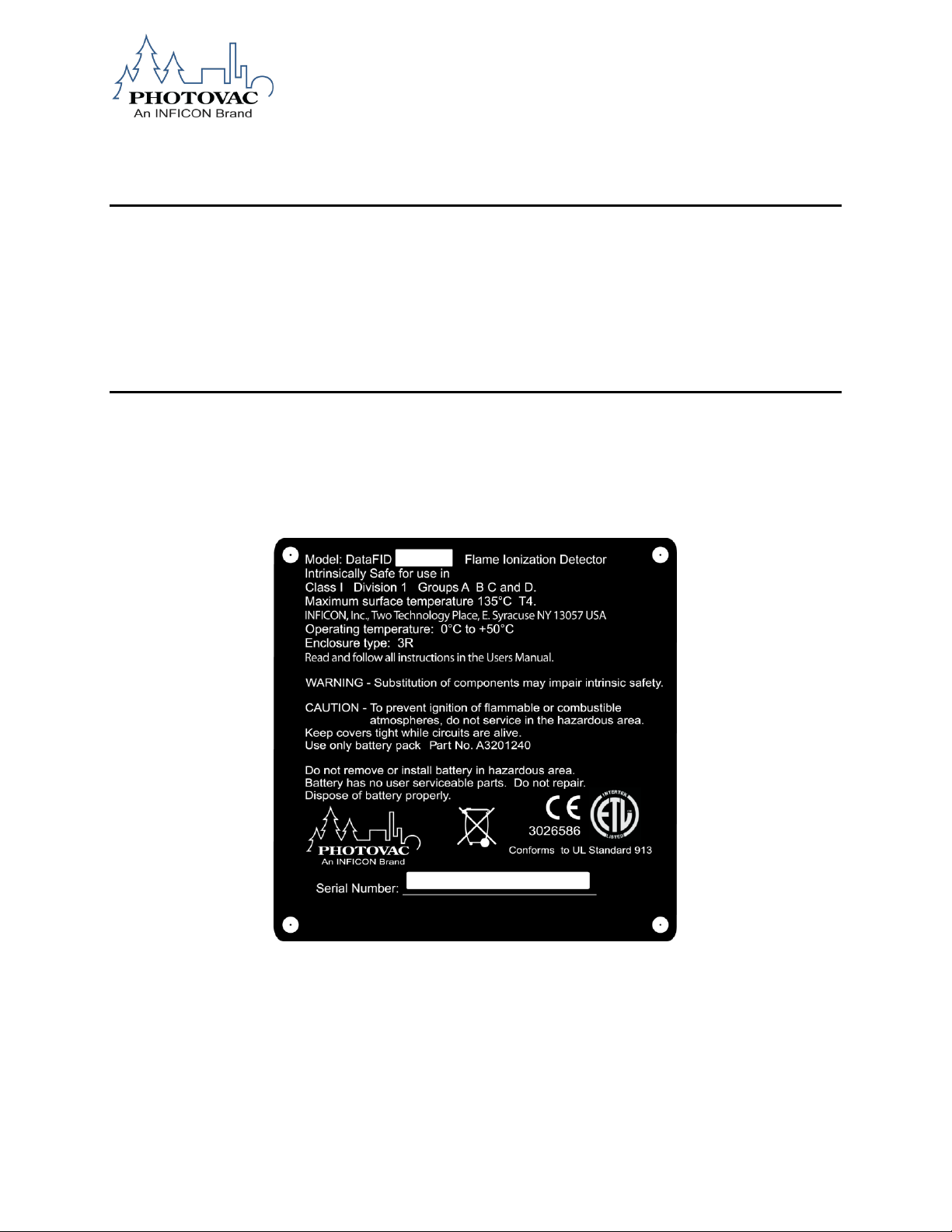
MicroFID II Safety Label
NOTE: The MicroFID II and MicroFID II are based on the same platform and contain the same
components. The terms may be used interchangeably throughout this manual.
074-579-P1A 8
Page 9
WARNING
If there is any indication of physical damage to the MicroFID II after it has
been dropped, the unit must be checked out by a service technician to
ensure instrument integrity.
.
WARNING
Do not use any other accessories with the MicroFID II in a hazardous
location
Substitution of components may affect the safety rating.
THE MicroFID II IS NOT INTENDED TO DETECT COMBUSTIBLE LEVELS OF GASES.
THE MicroFID II IS CLASSIFIED FOR USE IN ATMOSPHERES CONTAINING COMBUSTIBLE LEVELS
OF GASES.
CAUTION
To reduce the risk of fire or injury to persons, read and follow these instructions:
1. All calibration, maintenance and servicing of this device, including battery charging, must be
performed in a safe area away from hazardous locations. Disconnect all power before servicing.
2. There are no operator replaceable parts for the MicroFID II except the exhaust frit, and sample
inlet filter.
3. There are no operator serviceable parts inside the MicroFID II.
WARNING
1. Do not dispose of the battery pack in a fire. The cells may explode. The battery pack must be
disposed of properly. Check with local codes for possible special disposal instructions.
2. Do not open or mutilate the battery pack. If the MicroFID II is used in a manner not specified,
the protection provided by the MicroFID II may be impaired.
3. Exercise care in handling battery packs in order not to short the terminals with conducting
materials such as rings, bracelets and keys. The battery or conductor may overheat and
cause burns.
4. Do not defeat proper polarity orientation between the battery pack and battery charger.
5. Charge the battery pack using the AC battery charger provided with or identified for use with
this product only in accordance with the instructions and limitations specified in this manual.
To charge the battery, use only the Universal Battery Charger Part No. A1201221. When
using the battery charger, do not block access to the mains outlet in use with adapter. The
074-579-P1A 9
AC battery charger is not to be used in a hazardous area.
Page 10
WARNING
Do not open the MicroFID II housings to access the internal components.
This action will invalidate the Intrinsic Safety rating for these products
WARNING
1. All calibration, maintenance and servicing of this device, including battery charging, must be
performed in a safe area away from hazardous locations.
2. Disconnect all power before servicing.
3. Do not open the MicroFID II exhaust frit when the unit is operating.
074-579-P1A 10
Page 11

DECLARATION OF CONFORMITY
This is to certify that this equipment, designed and manufactured by:
INFICON Inc.
Two Technology Place
East Syracuse, NY 13057
USA
meets the essential safety requirements of the European Union and is placed on the market accordingly.
It has been constructed in accordance with good engineering practice in safety matters in force in the
Community and does not endanger the safety of persons, domestic animals or property when properly
installed and maintained and used in applications for which it was made.
In addition, this is to certify that this equipment has also been designed and manufactured, having regard
to the state of the art, to ensure compliance with the Protection Requirements of EMC directive
2004/108/EC.
A Technical Documentation File is also available for review by competent authorities and will be
maintained for a period of ten years after the date on which the equipment was last manufactured. In
addition to this file, technical, installation, maintenance and application information concerning this
equipment can also be found in the Operating Manual(s) for this product or product family.
Equipment Description: MicroFID II, MicroFID II, SiteFID.
Applicable Directives: 2006/95/EC (LVD)
1999/5/EC (R&TTE / EMC)
2004/108/EC (General EMC)
2011/65/EC (RoHS)
Applicable Standards:
Safety: UL 913, Fifth Edition; Dated February 21, 1997; with Revisions through
and including February 24, 1997, UL Standard for Safety for Intrinsically
Safe Apparatus and Associated Apparatus for Use in Class I, II, and III,
Division 1, Hazardous (Classified) Locations
ANSI/UL 1203-2006; Fourth Edition; Dated September 15, 2006,
UL Standard for Safety for Explosion-Proof and Dust-Ignition-Proof
Electrical Equipment for Use in Hazardous (Classified) Locations
ANSI/UL 61010-1-2008; Second Edition; Dated July 12, 2004,
(UL Standard for Safety for Electrical Equipment for Measurement,
Control and Laboratory Use)
Emissions: EN 61326-1:2006: FCC 47 CFR Part 15 Subpart B
(Radiated & Conducted Emissions)
Class B: Emissions per Table 3
(EMC – Measurement, Control & Laboratory Equipment)
074-579-P1A 11
Page 12

Countries
Restrictions
France
Outdoor use limited to 10mW e.i.r.p. within the band
2454 to 2483.5 MHz.
Italy
If used outside of own premises, general
authorization is required.
Luxembourg
General authorization is required for public service.
Romania
On a secondary basis. Individual license required.
Austria, Denmark, Finland,
Germany, Greece, Iceland,
Ireland, Liechtenstein,
Luxembourg, The Netherlands,
Norway, Portugal, Spain,
Sweden, Switzerland, The
United Kingdom
None
RoHS: INFICON hereby declares that the above mentioned products are
assigned to the classification of Category 9, Industrial Test and
Measurement Equipment, it is exempt from the RoHS directive pursuant
to Article 4, paragraph 4, section e), until 22 July 2017.
Immunity: EN 61000-4-5:1995+A1:1998+A2:2001
Electro Static Discharge (+4kV Contact discharge, + 8kV Air discharge)
EN61000-4-4:2004
Radiated RF Susceptibility (80-270 MHz @ 3 V/m, 1kHz AM 80%
Modulation)
Wireless Restrictions:
CE Implementation Date: May 15, 2012
Authorized Representative:
Name: Stephen Chabot
Title: Vice President of Operations and Quality
Done at East Syracuse, NY USA
On 13 August 2012
ANY QUESTIONS RELATIVE TO THIS DECLARATION OR TO THE SAFETY OF INFICON'S PRODUCTS SHOULD BE
DIRECTED, IN WRITING, TO THE VICE-PRESIDENT OF OPERATIONS AT THE ABOVE ADDRESS.
074-579-P1A 12
Page 13
WARNING
A warning indicates an operation that could cause personal injury if
precautions are not followed.
CAUTION
A caution indicates an operation that could cause damage to the
instrument if precautions are not followed.
NOTE
A note indicates significant information.
1. INTRODUCTION
About this Manual
This manual provides detailed instructions for the setup, operation and maintenance of the MicroFID II
Portable Flame Ionization Detector.
NOTE: The MicroFID II and MicroFID II are based on the same platform and contain the same
components. The terms may be used interchangeably throughout this manual.
Before unpacking the instrument, please read the Warnings and Safety Practices. This section
describes possible hazards that may injure the user, damage the instrument or compromise its operation.
Some general safety information is also provided.
The MicroFID II manual uses a few conventions for key names on the keypad and for text that is shown
on the display.
UPPERCASE Key names are denoted by uppercase text. An ARROW key is the
collective name for the UP ARROW and DOWN ARROW keys.
“Display Text” Text that appears on the MicroFID II display is in quotation marks.
<Angle Brackets> Computer keyboard names are denoted by angle brackets, e.g. <Ctrl>.
FID Text that must be typed in using the computer keyboard is shown in
italics.
In the User Manual text various warnings and notes are displayed, including:
074-579-P1A 13
Page 14
WARNING
The MicroFID II only measures the concentration of airborne gases and
vapors that can be ionized by a flame ionization detector.
The MicroFID II automatically displays and can record the concentration
values.
The reading displayed represents the total concentration of all flame
ionizable chemicals present in the sample. The MicroFID II can display
concentration values in ppm and ppb.
WARNING
Do not expose the instrument to intense sunlight for prolonged periods.
Exposure to excessive heat may result in erroneous readings.
At low temperatures, water vapor, a by-product of the hydrogen flame, may
condense at the exhaust port. At sub-zero temperatures the water vapor
will freeze and obstruct the exhaust port. If the exhaust port becomes
obstructed, pump operation will be inhibited. Flame out may also result.
UNPACKING THE MicroFID II
The following accessories are included with your MicroFID II:
MicroFID II Instrument CD Manual
70 Liter hydrogen cylinder
MicroFID II Multi-Tool
Universal Battery Charger with Line Cord
Replacement Fluoropore Membrane Filters for Sample Inlet
Ensure all of these accessories have been included with the instrument. If any items are missing or
damaged, contact INFICON immediately.
WARNINGS AND SAFETY PRACTICES
Please read this section before operating the MicroFID II.
Throughout this manual notes are provided to inform you of the limitations of usage for the MicroFID II.
Intended Use
Excessive Heat and Cold
074-579-P1A 14
Page 15
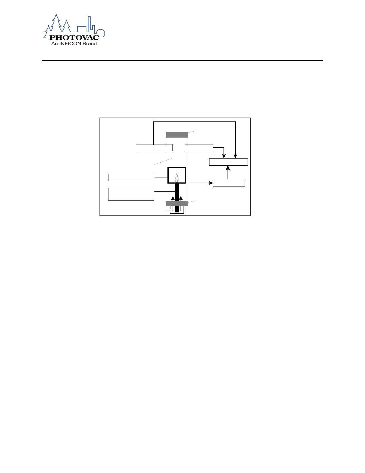
Electrometer
Repeller Electrode
(Jet +75 Volts)
Collector Electrode
Sample In
Exhaust Out
Flame Arrestor
Flame Arrestor
Microprocessor
Combustion Chamber
Glow PlugThermocouple
Flame Ionization Detector Operation
The MicroFID II uses a flame ionization detector for the measurement of combustible organic compounds
in air at parts-per million levels. The permanent air gases (argon, carbon dioxide, nitrogen, oxygen, water
vapor, etc.) are not ionized by the flame.
When the MicroFID II is flamed on, the internal pump draws air in through the MicroFID II inlet. This
sample air provides the oxygen necessary for combustion in the hydrogen fed flame.
Figure 1. Flame Ionization Detector
When the proper ratio of hydrogen to air is present in the combustion chamber, the flame is started
automatically with a glow plug. A thermocouple is used to monitor the status of the flame.
When the sample passes through the flame, the combustible organic compounds in the sample will be
ionized. After the compounds have been ionized by the flame, the ionized particles are subjected to a
continuous electric field between the repeller electrode at the jet (+75V) and the collector electrode.
The ions move in the electric field, generating a current, which is proportional to the concentration of the
ionized molecules in the ionization chamber. An electrometer circuit converts the current to a voltage that
is then fed to the microprocessor.
After the sample passes through the flame and has become ionized, it is vented from the detector through
a flame arrestor. The flame arrestor prevents the flame from igniting any flammable gases present in the
sampling location.
074-579-P1A 15
Page 16
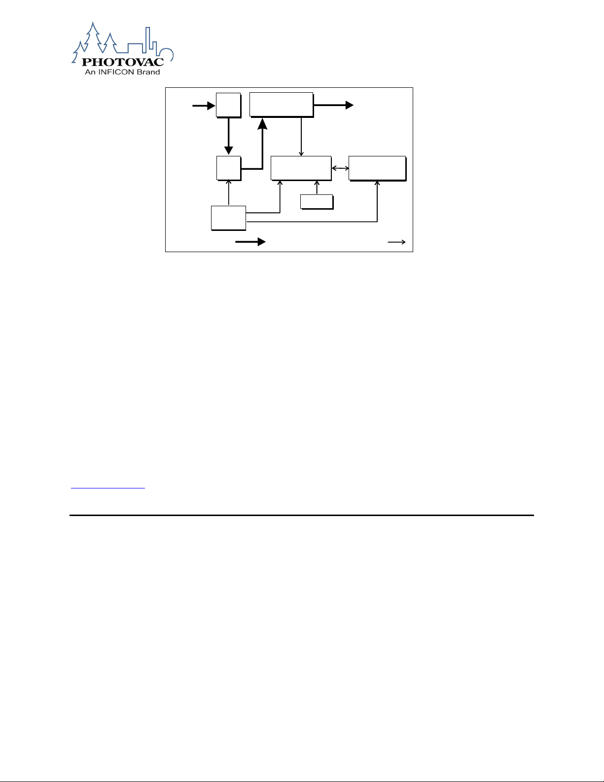
Display and
I/O Connector
Keypad
Microprocessor
Power
Supply
Electrical Connections
Sample Flow
Pump
Sample
In
Inlet
Filter
Flame Ionization
Detector
Detector
Out
Figure 2. Block Diagram
Detector Response
The MicroFID II is strictly an organic compound detector. It does not respond to inorganic compounds.
The MicroFID II’s sensitivity is highly dependent on chemical structure and bonding characteristics. The
combustion efficiency of a compound determines its sensitivity.
Simple saturated hydrocarbons (methane, ethane etc.) possess high combustion efficiencies and are
among the compounds that produce the highest MicroFID II response. Organic fuels (acetylene, refined
petroleum products), burn easily and are also extremely well detected.
The presence of substituted functional groups (amino, hydroxyl, halogens) on a simple hydrocarbon
reduces its combustion efficiency and thus MicroFID II’s sensitivity to the compounds methanol and
chloromethane, for example, are detectable with the MicroFID II but not as well as methane. A greater
number of carbon atoms can offset this loss of sensitivity due to substitution. For example, the MicroFID II
is more sensitive to n-butanol than it is to methanol.
NOTE: The FID Response Factors Technical Note is maintained on the INFICON web site:
www.inficon.com.
Support Equipment and Consumables
Compressed Gases
Cylinders of compressed gas, such as hydrogen and calibration gas, must be handled with extreme care.
When using the calibration gas bag adapter, take care not to kink or stress the tubing. For safety, the
hydrogen and calibration gas cylinders must be secured before use.
Please observe the following handling procedures:
Do not mutilate cylinders.
Do not expose the cylinders to direct sunlight.
Do not heat the cylinders. The cylinders may rupture at high temperatures.
Use only the specified regulator for the calibration gas. Confirm regulator type and material with
your specialty gas supplier.
Use only the MicroFID II Hydrogen Filling Station for the hydrogen cylinder, Part No. A1201222.
074-579-P1A 16
Page 17

WARNING
Hydrogen gas is a fire and explosion hazard when exposed to heat or
flame. The lower explosive limit (LEL) is 4%. The lower explosive limit is
the minimum concentration of gas or vapor in air that will ignite in the
presence of a source of heat or sparks.
Refer to the Material Safety Data Sheet (MSDS) before handling this gas.
The MSDS will be provided by the gas supplier when the gas is ordered.
Always secure cylinders before removing the cylinder valve protection cap.
Do not drag or roll cylinders. Use a cylinder hand truck to move large cylinders.
Wear safety glasses when working with compressed gases.
Store cylinders in an upright position.
Do not store cylinders in a hazardous location.
Store cylinders away from possible sources of ignition.
Keep regulators and related equipment in the same gas service. Do not change service or adapt
equipment without consulting your gas supplier.
Refer to local shipping regulations for hydrogen supply cylinder shipping instructions.
Regulators for Compressed Gases
When connecting a regulator to a large cylinder:
Ensure the cylinder valve and regulator connection match.
Ensure the regulator construction materials are compatible with the gas, and that the cylinder
pressure gauge will withstand the cylinder pressure.
Never use the regulator as a shut-off valve. Close the cylinder valve when it is not in use.
Do not subject the regulator to an inlet pressure greater than recommended.
Do not move or detach the regulator when it is pressurized or when it is in use.
Before connection, ensure the gas cylinder valve and the regulator CGA connection are clean.
Turn the pressure control valve on the cylinder all the way out (close the cylinder). Turn the
regulator outlet to off. Open the gas cylinder valve slowly and check for leaks. Adjust the delivery
pressure and then open the regulator outlet valve.
Hydrogen Gas
The MicroFID II detector uses a hydrogen flame to ionize samples and produce Total Volatile Organic
Compound (TVOC) readings. The quality and purity of the Hydrogen gas is very important to the
accuracy of the detector.
074-579-P1A 17
Page 18

You must obtain a tank of hydrogen from which you can fill the internal cylinder. When ordering hydrogen,
specify ultra-high purity hydrogen, 99.999% pure. This grade of hydrogen is also referred to as Grade 5 or
Ultra zero grade. The hydrogen must have less than 0.1 ppm hydrocarbon contamination.
You can obtain the hydrogen in various size cylinders and pressures. Specify a tank with no more than
2400 psig (16547 kPa).
The hydrogen cylinder must also have CGA 350, male outlet.
The MicroFID II Hydrogen Filling Station Part No.A1201222 is required to fill the MicroFID II hydrogen fuel
cylinder. You cannot fill the MicroFID II hydrogen cylinder without the MicroFID II hydrogen filling station.
Calibration Gas
Adequate ventilation must be provided when the MicroFID II is being calibrated.
If compound threshold limit values (TLV) are exceeded, you should use a gas bag for sampling and
calibration.
To determine the TLV of the compounds contained in the calibration gas, refer to the Material Safety Data
Sheet (MSDS) supplied with your calibration gas cylinder.
Oxygen Concentration Limits
A minimum of 17% oxygen is required to start the hydrogen flame. The oxygen is supplied from the
sample as it is drawn in by the pump. A minimum of 10% oxygen is required to maintain the hydrogen
flame. An oxygen deficiency will reduce the height of the flame or cause the flame to be extinguished and
may affect the displayed reading.
If the MicroFID II is used in a highly contaminated area where it is possible that the oxygen content is
below 10%, watch for indications of reduced flame height such as lowered detection limits or a flame out
fault.
Flammable Gases
High concentrations of flammable gases (gases within their flammable range) can act as an additional
fuel source. When this happens, the flame height may increase beyond the confines of the combustion
chamber. The hydrogen supply will then be cut off and the flame will go out.
Flame out may also occur when the concentration of sample gas is so great that it causes an oxygen
deficiency. This may occur when sampling enclosed or confined spaces where vapors and gases cannot
escape. Watch for indications of increased flame height such as erratic readings or sudden high
concentrations followed by a flame out fault.
074-579-P1A 18
Page 19
WARNING
The MicroFID II is not classified for use in hazardous locations with nonintrinsically safe rated computers.
ACCESSORIES
Computer
The MicroFID II will send information stored in its logged memory or will continuously stream data to a
computer or PDA via Bluetooth wireless communication. This feature may be used if you need to prepare
reports based on the MicroFID II recorded data.
Information prepared on a PC such as “routing or tag information” may be uploaded to the MicroFID II via
Bluetooth as well.
Gas Sampling Bag
A gas sampling bag can be used for calibration of the MicroFID II. If you are unsure of the quality of
ambient air you should use an additional gas bag filled with zero air. Connect the sample bag to the inlet
fitting with the gas bag adapter. See Calibration section for more information.
One sampling bag is included in the MicroFID II calibration kit Part No. MX396011. Additional gas bags
are also available (Part No. MX396017).
Charcoal Filters
A charcoal filter (Part No.MX396022, package of 10) may be connected to the MicroFID II during
calibration and sampling to provide clean air to the MicroFID II. The filter will remove hydrocarbon
contamination from room air to provide zero grade air to the MicroFID II.
NOTE: The charcoal filter does not filter methane or ethane. If these compounds are present, you should
use a gas bag with a supply of commercial zero air for calibration purposes.
074-579-P1A 19
Page 20
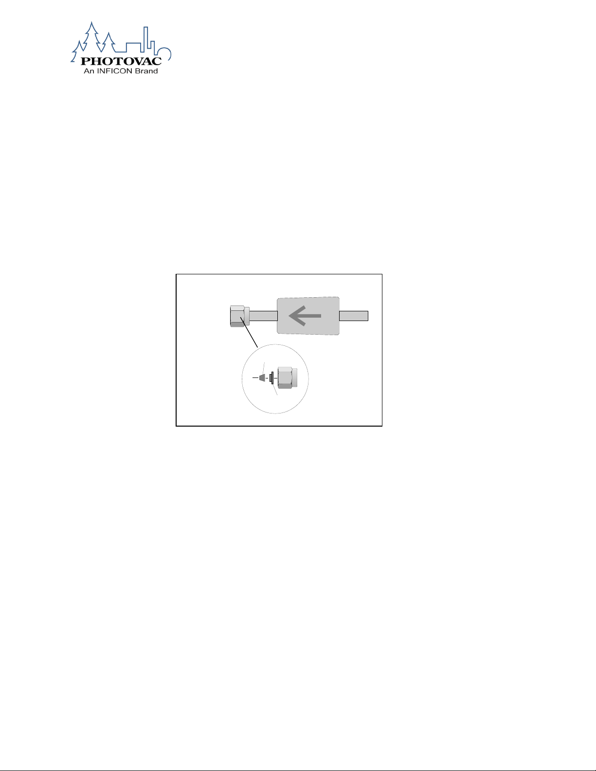
1/4" Nut
Connect
to MicroFID
Charcoal Filter
Front Ferrule
Back Ferrule
To connect a charcoal filter:
1. Load the Teflon ferrules into the nut. The nut and ferrules are supplied with the filter. See
Figure 3.
2. Connect the nut to the MicroFID II inlet. Do not tighten the nut.
CAUTION: Over-tightening the Teflon ferrules will result in damage to the ferrules.
3. Remove the charcoal filter from its plastic bag and insert it into the nut. Finger-tighten the nut
onto the inlet. If the filter is not secure, ensure you have inserted the tube stub far enough into
nut. Do not over-tighten the fitting.
Figure 3 Connecting the Charcoal Filter
The charcoal filter will remove hydrocarbon contaminants for up to 4000 ppm hours. This means that the
filter will be good for 1 hour removing 4000 ppm of hydrocarbon contaminants or will last for 4 hours
removing 1000 ppm. The exact time will be determined by the operating environment. You will notice an
increased hydrocarbon background when the filter requires replacement.
To replace the charcoal filter:
1. Loosen the nut on the MicroFID II inlet.
2. Remove the used filter.
3. Insert the new charcoal filter into the nut and finger-tighten the nut onto the inlet. Do not over-
tighten the fitting.
4. When the charcoal filter is not in use, place it in its plastic bag and store it in a clean, dry place.
074-579-P1A 20
Page 21
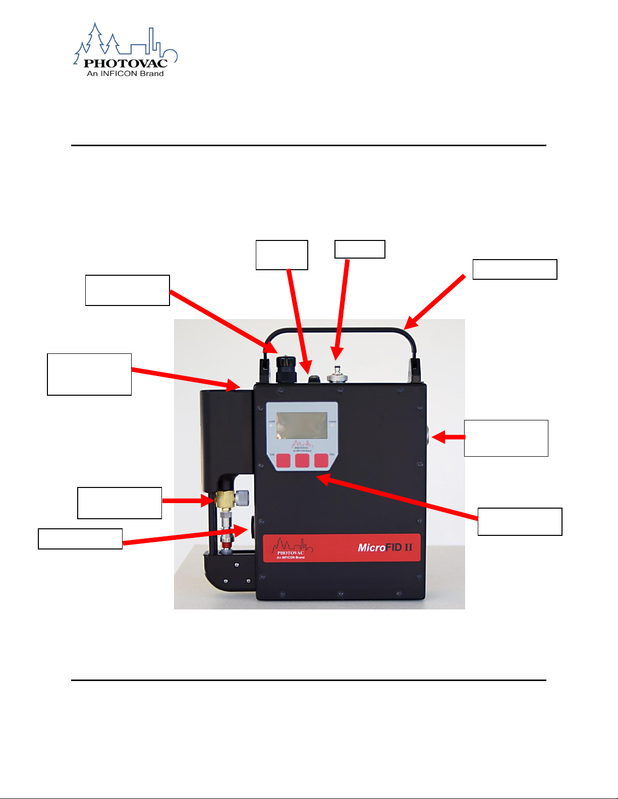
Hydrogen Fuel
Cylinder
Retention Plate
Handle
Inlet
On/Off
Switch
AC Charging
Connector Cap
Digital Display
and Soft Keys
Hydrogen Fuel
Cylinder
Alarm Speaker
Exhaust Frit
2. USING THE MicroFID II
MicroFID II Feature Layout
The photograph below shows the basic layout of the MicroFID II Version components. The MicroFID II is
also supplied with an optional telescoping probe that can be removed from its holder for access to hard to
reach spaces.
NOTE: The cover must be attached for the MicroFID II to operate and to maintain the intrinsic safety
rating.
074-579-P1A 21
Page 22
MicroFID II with probe in probe
holder position
MicroFID II with probe in
telescoping position
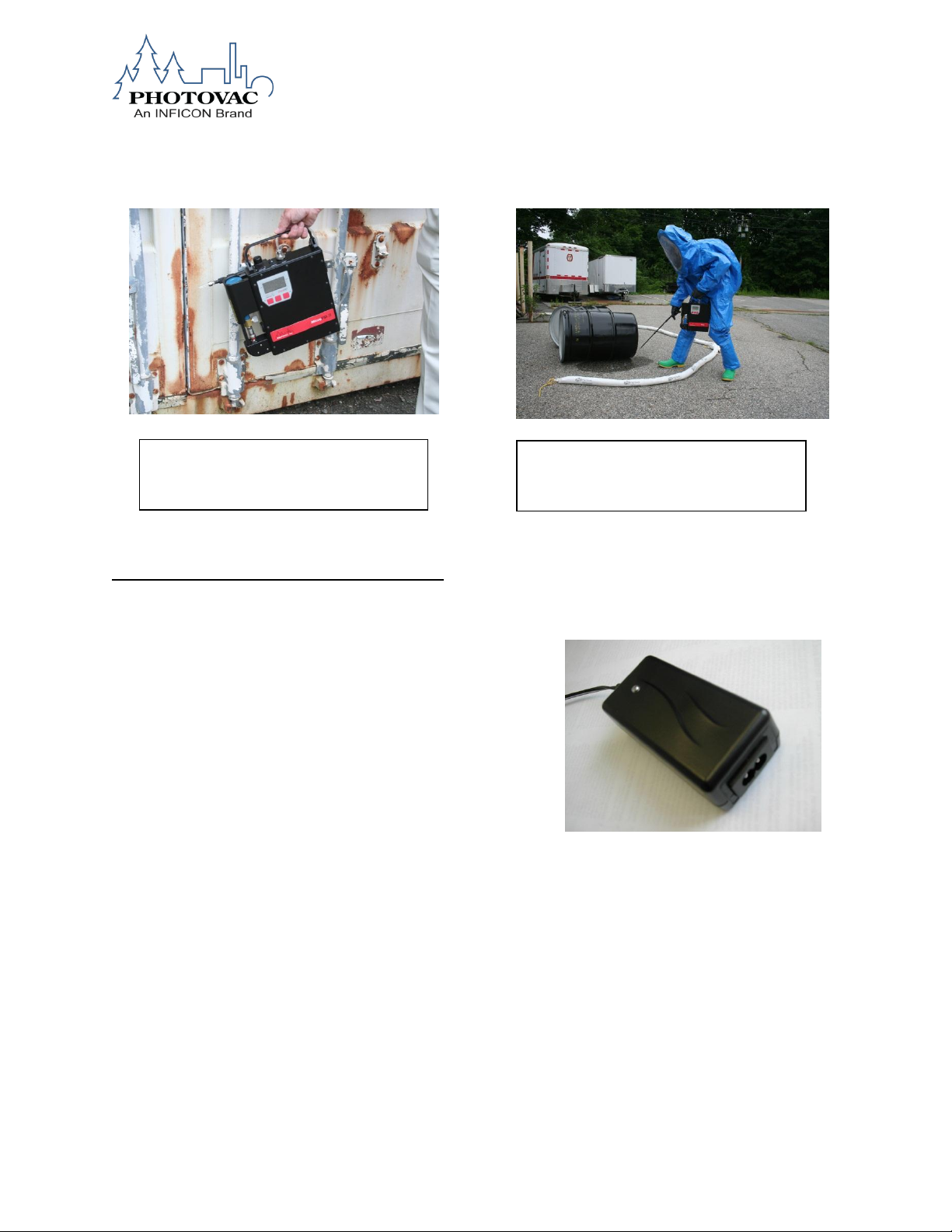
Using the MicroFID II Battery Charger
READ THESE INSTRUCTIONS BEFORE USING THE CHARGER
The MicroFID II battery charger is only designed for indoor use
and should not come into contact with water or dust. In order to
avoid overheating, the charger should not be covered when it is
in use.
The charger is turned on by connecting it to the mains socket.
Disconnecting it from the mains socket turns the charger off. If
the charger is equipped with a mains cord, verify that the cord
has not been damaged. If the cord is damaged, the charger
must not be used.
The charger contains dangerous voltages and the cover should not be removed.
CHARGER FUNCTIONALITY
This charger is a fast charger for NiMH batteries. The charger will automatically charge the battery at a
fast rate, and then charge to a slow rate near the end of the cycle. This prevents over-charging.
CAUTION: Do not charge batteries at too high or too low temperatures. Charge only in areas between
38-110°F (3-43°C).
074-579-P1A 22
Page 23

LED
MODE
Orange
Battery not connected
Orange
Battery initialization & analysis
Red
Fast Charge
Green with intermittent orange flash
Top-off charge
Green
Trickle charge
Alternating red-green
Error
HOW TO USE THE CHARGER
The Charger is started by connecting the battery pack to the charger. Once connected, the indicator LED
will start Orange, for the Initialization and Analysis Phase, before switching to Red for the Fast Charge
Phase. When the batteries are fully charged, the charger will go into a top-off charge mode before it goes
over to trickle charge mode. During top-off charge, the LED will be Green with short intermittent Orange
light. When the top-off charge is completed, the charger will go into trickle charge mode and the LED will
be Green. The charge current is now reduced to a safe level, which allows the charger to stay connected
to the NiMH batteries without damaging the battery. If the battery voltage is far below normal, the charger
will cut off the fast charge current and go to trickle charge mode. The LED will then indicate ‘error’ by
flickering Green and Red light. If the mains is turned off, the charger will reset and start a new charge
cycle if the mains is turned on again. If new batteries are to be connected, the charger must idle for
approximately 15 seconds to make sure all parameters in the microprocessor have been reset. The LED
changing to Orange light shows this and a new charge cycle can begin.
.
CHARGE CYCLE AND LED INDICATIONS
With mains connected, the LED will be orange the first 5-7 seconds, and will be orange when the
initialization and analysis starts. If a battery is connected, the actual charging will start a few seconds later
when the LED changes to red.
CAUTION: Use only Battery Charger P/N 1201221 to charge the MicroFID II.
074-579-P1A 23
Table 1. Battery Charger Indications
Page 24
To Charge the Battery
1. To charge the MicroFID II battery, unscrew the cover for the charging connector cap.
2. Connect the charge adapter to the MicroFID II charging connector.
3. When the battery charge indicates there is a full charge to the battery, disconnect the charge
adapter from the MicroFID II charging connector
4. Install the charging connector cap to the charging connector.
074-579-P1A 24
Page 25

NOTE: The MicroFID II will not operate without the charging connector cap in place.
NOTE: The MicroFID II will not operate with the AC Adapter plugged into the MicroFID II.
Repeat Charging with an AC Charger
If the AC charger has been plugged into an electrical outlet and has been used to charge a FID, and
another charging operation is to be performed, please remove the charger from the unit and wait until the
status LED on the charger changes from either green or red to orange before plugging it into the second
unit.
NOTE: The status change will take up to 15 seconds and the orange LED indicates that the unit
is ready to start a new charge cycle.
CAUTION: If the AC charger is not properly reset according to the above instructions, it is
possible that the AC charger will remain in trickle charge mode and the FID battery will not
receive a full charge. This will limit the FID’s operating time and may cause problems in lighting
the FID flame due to low voltage.
Filling the Hydrogen Fuel Cylinder
The MicroFID II hydrogen fuel cylinder is a metal hydride design that requires relatively low hydrogen
pressure to fill it.
Figure 7. MicroFID II Hydrogen Cylinder
074-579-P1A 25
Page 26
WARNING
Hydrogen storage on the metal oxide is an Exothermic Reaction. The
cylinder may become hot during the initial fill. Care must be taken to avoid
injury.
WARNING
DO NOT attempt to fill the hydrogen cylinder without a refill adapter..
The hydrogen fuel cylinder (see Figure 7), when full, will provide the MicroFID II with up to 70 hours of
continuous operation in a single fill. To fill the hydrogen fuel cylinder, the MicroFID II hydrogen filling
station Part No. A1201222 is required (see Figure 8). The hydrogen fill station is outfitted with a CGA 350
adaptor for use with a high pressure hydrogen cylinder that contains at least 99.999% pure grade
hydrogen (also known as ultra high purity hydrogen).
CAUTION: H2S, SO2, Cl2, and CO are contaminating substances for the cylinder alloy. Do not expose the
cylinder interior to these substances.
CAUTION: Lower grades of hydrogen will damage the fuel cell with impurities and decrease the overall
longevity of the fuel cell. Ensure the hydrogen is ultra high purity.
CAUTION: Do not modify or alter the hydrogen cylinder or fittings.
The Hydrogen Filling Station (Part No.A1201222) consists of an adapter fitting with a left-handed thread
for cylinder attachment, an output valve and a hydrogen fuel cylinder quick connect. The Hydrogen Filling
Station delivers a fixed 260 psi to the hydrogen fuel cylinder. The output valve is positioned to deliver gas
from the cylinder to the hydrogen fuel cylinder. Additionally, in the final stages of filling the hydrogen fuel
cylinder, the output valve is used to release gas held in the quick connect after filling.
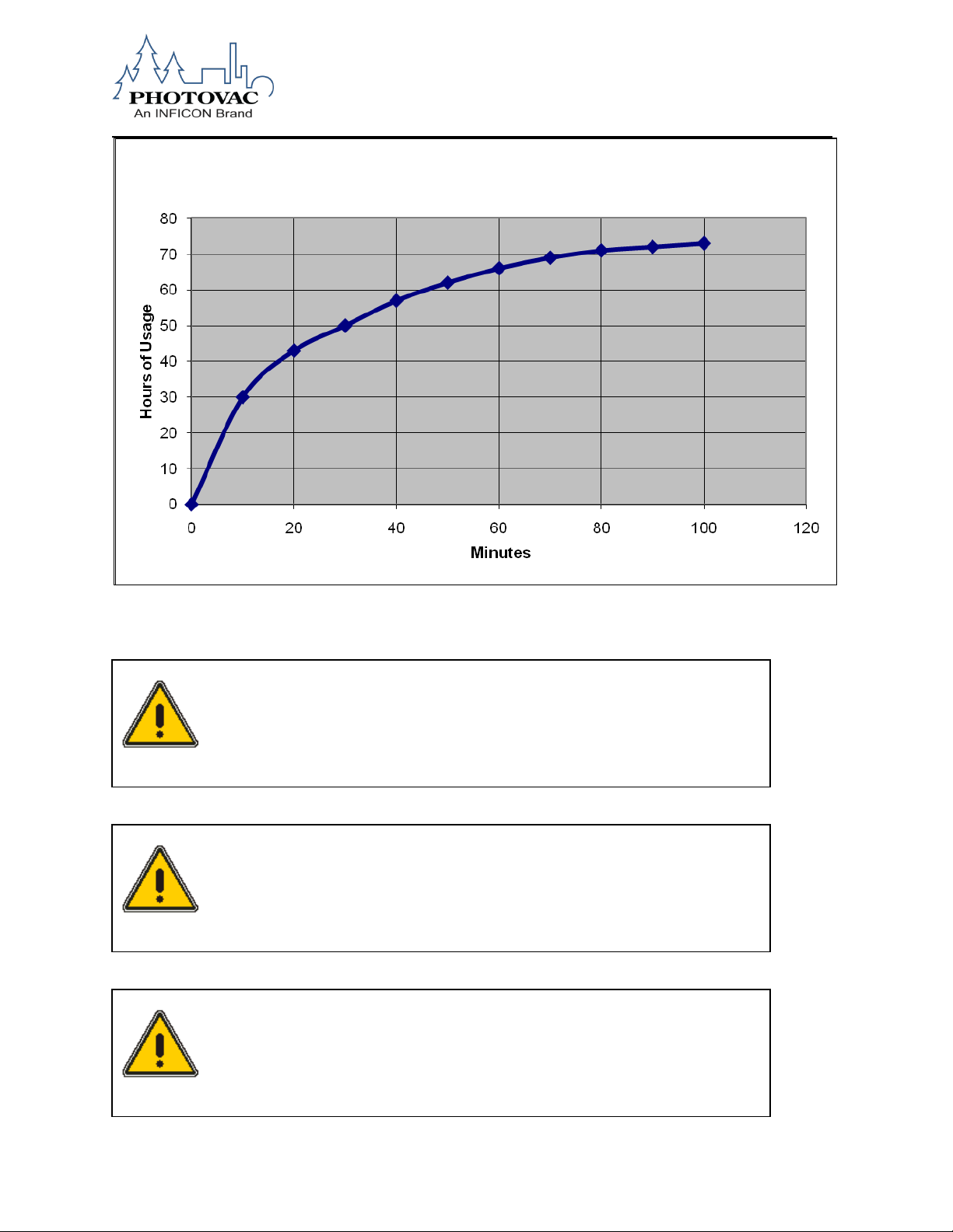
The MicroFID II Hydrogen Fuel Cylinder is composed of metal hydride material. The process of filling this
cylinder involves the low pressure adsorption of hydrogen on the metal hydride surface, rather than the
high pressure filling process for conventional hydrogen cylinders. Table 2 illustrates the charge time
versus fill time for the MicroFID II hydrogen cylinder.
A 5 minute charge provides 10 hours of usage. Other charge times versus usage are as follows:
5 minutes 10 hours of use
10 minutes 30 hours of use
30 minutes 50 hours of use
60 minutes 65 hours of use
The hydrogen fuel cylinder is over 85% full after one hour. Thereafter, the cylinder charges more slowly
up to the full 70+ hours.
074-579-P1A 26
Page 27
WARNING
Use only the MicroFID II Hydrogen Fill Station p/n A1201222 to fill the
hydrogen cylinder. Use of any other filling device will void the warranty.
WARNING
The regulator pressure is set at the factory Do not adjust the regulator on the
hydrogen filling station. Adjustment of the hydrogen filling station regulator
will void the warranty.
WARNING
Do not exceed 260 psi when filling the MicroFID II Hydrogen Cylinder. The
fuel cells in the hydrogen cylinder will be damaged and will void the
warranty.
MicroFID II Hydrogen Cylinder Charge Chart
Table 2. Charging Time and Usage Time
074-579-P1A 27
Page 28

WARNING: FIXED REGULATOR, DO
NOT ATTEMPT TO ADJUST
Output Valve
Attach Hydrogen Fuel
Cylinder Here
Hydrogen Cylinder
on/off valve
CAUTION: When filling the MicroFID II Hydrogen Cylinder, ensure that the hydrogen cylinder on/off valve
is completely open in the counterclockwise position.
Figure 8. Hydrogen fuel cylinder on/off valve
074-579-P1A 28
Figure 9. Hydrogen Fuel Cylinder Filling Station
Page 29

WARNING
Hydrogen gas is a fire and explosion hazard when exposed to heat or flame.
The lower explosive limit is 4%
WARNING
DO NOT Use an open flame to test for leaks!
WARNING
DO NOT fill the hydrogen cylinder in a hazardous location.
NOTE: Read through this section before filling the hydrogen fuel cylinder.
Store the hydrogen supply tank in a well ventilated area, well away from heat or possible ignition sources.
Directions for Attaching the Hydrogen Filling Station to the Hydrogen Supply Tank
1. Connect the hydrogen fuel cylinder filling station to the tank of hydrogen. Hydrogen is supplied with a
CGA 350 cylinder valve outlet. The filling station is supplied with the matching fitting for ease of
connection. The threads of the adaptor will tighten counterclockwise.
NOTE: Do not force the connection. Do not use Teflon tape with CGA fittings. In general, these fittings
are designed for metal to metal sealing.
Do not use adapters to connect one CGA fitting to another type of CGA fitting. If the refill adapter does
not match the outlet on your hydrogen tank, contact INFICON.
2. Tighten the hydrogen cylinder filling station onto the tank with a wrench. Do not over tighten.
074-579-P1A 29
Page 30

Filling Position
Venting Position
Filling the Hydrogen Fuel Cylinder
1. Rotate the output valve to point toward the main cylinder of hydrogen (Filling Position)
Figure 9. Output Valve
2. Attach the MicroFID II hydrogen fuel cylinder to the quick connect mate on the hydrogen filling station
(see Figures 8 and 10).
3. Open the on/off valve on the hydrogen fuel cylinder. See Figure 8.
4. Open the valve on the hydrogen supply tank.
5. Allow the unit to fill for the amount of usage time required as per the above chart.
NOTE: The hydrogen fuel cylinder will become warm during the filling process and will be warm to the
touch. Once the fuel cells are full, the cylinder will begin to cool down and become room temperature.
Hydrogen cylinders that are only partly depleted of hydrogen may take less time to fill.
6. Close the valve on the main cylinder of hydrogen
7. Rotate the output valve to point away from the main cylinder of hydrogen, (Venting Position)
8. Wait approximately 5 seconds, and then rotate the output valve once again toward the main cylinder of
hydrogen. (Filling Position)
9. Disconnect the full hydrogen fuel cylinder from the quick connect on the filling station by holding the
release ring of the hydrogen fuel cylinder with one hand and holding the red release ring with the other.
Push up the hydrogen fuel cylinder release ring and the hydrogen fuel cylinder will be separated from the
hydrogen fill station. The hydrogen fuel cylinder will be cool to the touch when it is remove from the
hydrogen fill station. With time, the hydrogen fuel cylinder will become room temperature.
10. Ensure the main hydrogen supply tank valve is closed.
11. If the hydrogen cylinder will not be used immediately after the filling process is complete, close the
hydrogen cylinder by turning the on/off valve completely clockwise.
074-579-P1A 30
Page 31

Hydrogen
Tank
Valve
Warning: Do not
adjust this
regulator
Output
Valve
Red release
ring
Hydrogen fuel
cylinder
release ring
Figure 10. Hydrogen Fuel Cylinder Connected to Filling Station
074-579-P1A 31
Page 32

Hydrogen Fuel Cylinder
Retention Plate
Hydrogen
Fuel Cylinder
Holder
MicroFID II
Hydrogen
Fuel Inlet
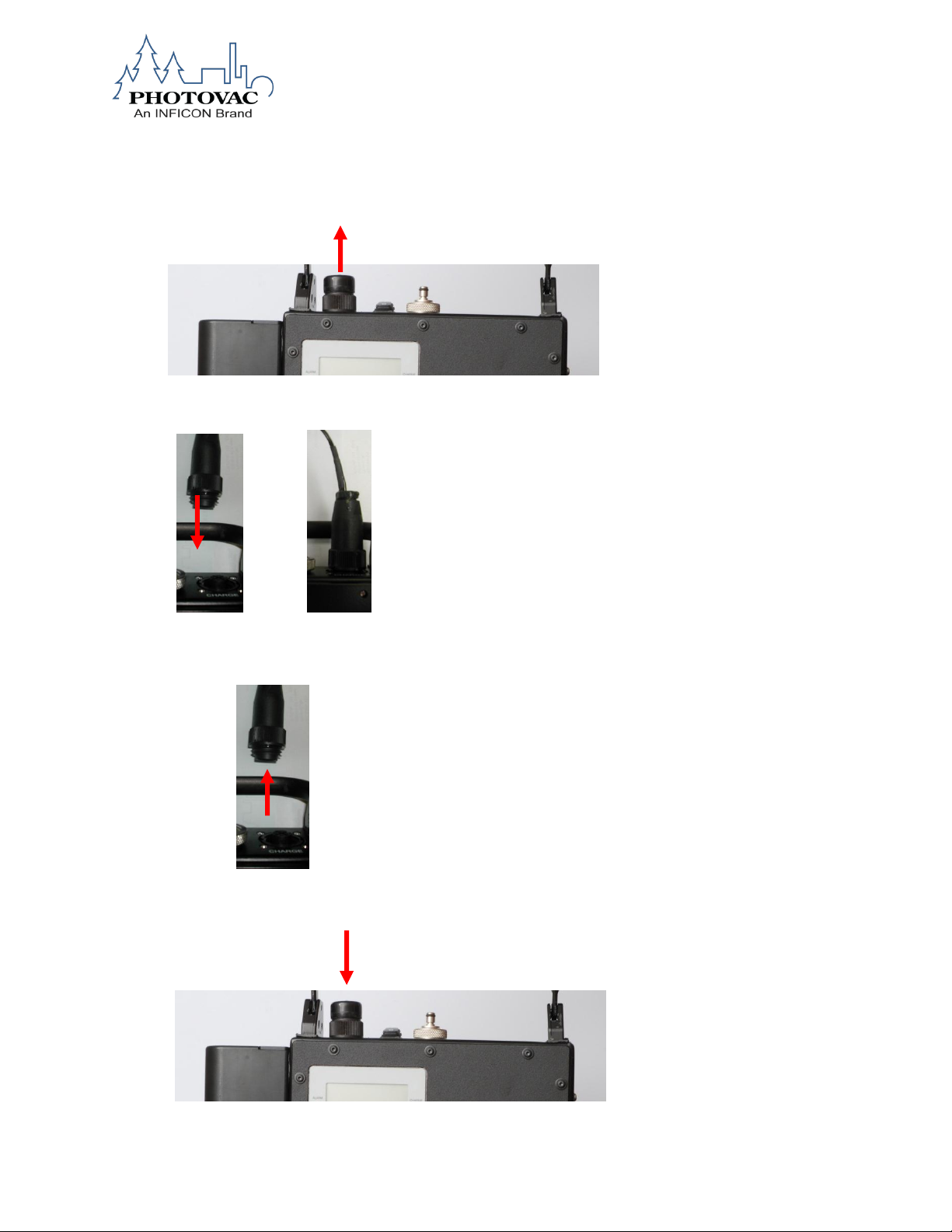
Installing the Hydrogen Fuel Cylinder in the MicroFID II_____________________________
1. If the hydrogen fuel cylinder retention plate is installed on the MicroFID II, remove it and
set it aside.
2. Insert the hydrogen fuel cylinder into the hydrogen
fuel cylinder holder.
3. Guide the hydrogen fuel inlet into the MicroFID II
hydrogen fuel inlet.
4. Push the hydrogen fuel cylinder until you hear a
distinct click.
5. Attach the hydrogen fuel cylinder retention plate
with the two set screws.
074-579-P1A 32
Page 33

WARNING
The hydrogen fuel cylinder retention plate MUST be installed on the
MicroFID II to retain the intrinsic safety rating.
I
o
6. Open the hydrogen fuel cylinder on/off valve if monitoring is to be started.
Attaching the Telescoping Probe to the MicroFID II
1.. The Telescoping Probe has a knurled nut fitting. Simply screw in the knurled nut into the
MicroFID II inlet.
Basic Operating Instructions
The following steps should be followed to operate the basic functions of the MicroFID II.
1. Ensure that the MicroFID II battery has been fully charged.
2. Attach the hydrogen cylinder to the left side of MicroFID II instrument body. The cylinder slides through
an open holder, and the swage connector engages the cylinder with the instrument. A distinct click will be
heard when this occurs.
3. Install the hydrogen cylinder holding plate with the two screws that are attached.
4. Turn on the hydrogen fuel cylinder on/off valve (see Figure 8) by rotating the knob counter-clockwise.
Wait a few minutes for the hydrogen fuel to flow to the MicroFID II detector.
5. Turn on the MicroFID II using the “OFF /ON” power switch on the top right of MicroFID
II instrument body. On is the symbol” l” and off is the symbol “o”.
6. The display screen on the probe will show the “Top Level Menu” depicted in the
Section: User Menu Functions.
7. The MicroFID II body display has three red soft keys (see Figure 6) that operate all
menu functions facilitating single handed use of the instrument.
074-579-P1A 33
Page 34

8. The MicroFID II will automatically start with “MicroFID II Setup” on the main display. Simply press the
middle red soft key (“meas”) to initiate the “Flame ON Procedure.” After a few moments, measurements in
ppm should be shown on the display, and the flame icon should be present.
9. The calibration function is initiated by pressing both the left and right soft keys at the same time.
NOTE: See Calibration section immediately following these steps for a full discussion on the calibration
process.
10. To turn off the MicroFID II, follow the steps shown on the Shut Down MicroFID II Menu, Figure 15 in
Chapter 3 User Functions.”
Calibration
The MicroFID II must be calibrated in order to display concentration in ppm units equivalent to the
calibration gas. See the section on calibration starting on page 59 for a full description of calibration
procedures for the MicroFID II. The MicroFID II must be operated in an upright position during calibration.
Data Communication
The MicroFID II links to external devices via Bluetooth. This wireless technology is used as the
communication link to external PC’s used for uploading information to the MicroFID II and for
downloading measurement data collected during the process of field monitoring activity. It can also
communicate with external PDA’s which may be used for Method 21 LDAR monitoring
Refer to Chapter 4 for more information regarding Bluetooth communication set-up and operation.
Response Factors for Gases and Vapors
To use the response factors:
1. Press the CAL key and enter the response factor for the specific compound.
2. Calibrate the MicroFID II with zero air and 500 ppm methane as described in the section on
calibration
3. Expose the MicroFID II to the sample. The displayed reading is the approximate concentration
of the specific compound.
The response factors on the INFICON web site serve as a guide to concentrations measured by the
MicroFID II.
NOTE: It does not matter which Cal Memory is selected or which response factor is entered, MicroFID
II’s response is not specific to any one compound. The displayed reading represents the total
concentration of all ionizable compounds in the sample.
074-579-P1A 34
Page 35

Calibration kit(s) (Part No. MX396011)
Tank(s) of calibration gas (Part No. MX396028)
Spare gas bag for zero air (Part No. MX396017)
Gas bag adapter for zero air (Part No. MX396010)
Supply of commercial zero air
Charcoal filters (Part No. MX396022, pkg. 10)
Spare inlet filters (Part No. MX396015, pkg. 25)
MicroFID II Operating Manual (Part No. 074-579-P1)
Battery charger (Part No.A1201221)
Hydrogen Filling Station (Part No. A1201222)
Hydrogen fuel (Part No. MX754112)
Computer or PDA
Preparing for Field Operation
Field Check List
The following items should be carried into the field to reduce or eliminate instrument down time. If you will
be in the field for a single 8-10 hour day, you should include the following accessories:
Table 3. Check List for Field Operation
If you will be in the field for more than one day you should include the following additional items:
Table 4. Additional Field Items
074-579-P1A 35
Page 36

Operational Check List
Before beginning field work, set up and calibrate the MicroFID II for your particular application. Ensure the
instrument is in working order before heading into the field.
To prepare the MicroFID II for field work
1. You should not transport the MicroFID II with the hydrogen fuel cylinder attached to the
MicroFID II. Remove the hydrogen fuel cylinder from the MicroFID II and package it individually
for transport.
2. Press the SETUP key and ensure the correct date and time are entered.
3. Program and calibrate all the Cal Memories you will be using. After calibration is complete,
sample the bag of calibration gas and the bag of zero air to ensure the MicroFID II has been
calibrated correctly.
4. If you are using an averaging interval, you may also want to delete all events from the
datalogger to avoid confusion between different days’ data and to avoid running out of space in
the datalogger.
5. If you are performing Method 21 monitoring, ensure you have programmed and
calibrated all the Cal Memories. You must also program your monitoring schedule.
074-579-P1A 36
Page 37

Soft
Keys
Calibration
gas used
Hours of
hydrogen
usage
remaining
Battery
status
Flame-on
icon
Charging
light
Alarm
light
Time
Menu
Bar
3. USER FUNCTIONS
Display
The MicroFID II has a graphic display for reporting detected concentrations and to guide you through
configuration options. All functions of the MicroFID II will be reported on the display.
Graphic Display
The MicroFID II uses an 8 line graphic display. The display will always be used for reporting
detected concentration. In order to accommodate the range of concentrations the MicroFID II can
detect, the meter reading will be reported using one of three resolutions. A resolution of 0.01
ppm will be used for concentrations below 10 ppm, a resolution of 0.1 ppm will be used for
concentrations between 10 ppm and 999.9 ppm, and a resolution of 1 ppm will be used above
1000 ppm.
Figure 11. MicroFID II Display
074-579-P1A 37
Page 38

main menu
Data log
Menu
Download log to
Edit log interval
Verify BlueTooth
continue
Clear data log?
Yes or No
Enter New interval mode
Logging time (0-000 secs)
Sends logged data to
connection
Yes clears data log
No leaves data intact
Figure 13. Data Log Options Menu
View Menu
MicroFID II Setup
Data Log Options
Shutdown MicroFID II
meas
select
Menu Function Displays
Figure 12. The MicroFID II Main Menu Display
The display reports instantaneous concentrations at all times when the flame is on. There are
four User modes: Logging Off, Interval, Location, and Method 21. In all four modes, the display
will report instantaneous concentrations.
The MicroFID II is designed for ease of use with a logically organized internal menu
structure/user interface.
The four submenus for the MicroFID II are expanded in Figures 13, 14, 15, and 16.
The MicroFID II has three soft keys, and they are located under the graphic LCD display. Each
display screen will always show the available functions of the soft keys.
Options
connection between
MicroFID II and the
PC. Hit ‘next’ to
PCD
Clear data log
the PC via BlueTooth
074-579-P1A 38
Page 39

MicroFID II Setup Menu
Audio ON
Audio OFF
Pump ON
Pump OFF
Method 21
Interval
Optional Air ON
Optional Air
OFF
Backlight ON
Backlight OFF
Edit Current Date
Edit Current Time
DD/MM/YYYY
MM/DD/YYYY
Enter New 4
digit password
English
PPM
PPB
RT Output ON
RT Output OFF
Compound 1
Compound 7
Hexane Cal
Propane Cal
FW Boot Load
Diag Monitor
Turn Flame ON
Audio Control Menu
Pump
Optional Air
Backlight
User Mode
Clock
Date Format
Password
Language
Units
Real Time Data
Compound
Selection
Select Cal Gas
Service Diagnostics
Audio ON
Audio OFF
Turn Pump ON
Turn Pump OFF
Turn Optional Air ON
Turn Optional Air OFF
Turns display Backlight ON
Turns display Backlight OFF
Measures in Meth 21 mode
Measures in interval mode
Edit date mm/dd/yy
Edit time of day hh:mm
Commands MicroFID to
send data via Bluetooth
Display in parts per
Display in parts per billion
Other languages to be
added at later date
Change current
password
US date mm/dd/yy
Intl date dd/mm/yy
Performs selected diagnostic
problems
Methane Callib Gas is used
Hexane Calib Gas is used
Selects Compound Gas and
active meas
Edit H2 Timer
Enter 2 digit H2
time in hours
Sets time remaining for H2
tank
Figure 14. MicroFID II Setup Menu
Logging Off
Location
Measures w/no logging
Measures in location mode
million
074-579-P1A 39
to
Methane Cal
Signal Test
Glowplug Test
Hydrogen
Range
associated Response
Factor, Alarm level for
Propane Calib Gas is used
routine to help troubleshoot
Page 40

Shut Down
MicroFID II
Shut down in
soft key to continue
Shutdown Complete
Turn MicroFID II OFF
View
Menu
List Tag Strings
Sample Log Data
Tag Description 1
Tag description “n”:
Provides Read-only
number, etc.
Provides Read-only
3 09:51 32.6
Provides the user
selected Tag
Serial #: A123
Key Audio: OFF
process Press ‘next’
Turn Valves OFF
Figure 15. Shut Down MicroFID II Menu
Setup Configuration
Figure 16. View Menu
Tag description 2
…
description of the
MicroFID current
parameter setup,
SW version, serial
view of the current
data log, example:
1 09:49 14.5
2 09:50 22.9
with a way to view
and/or edit the
SW Ver: 1.01
Battery: 9.79 volts
Pump Curr: 1.79 mA
Flame State: ON
Calib Gas: Methane
Air Option: OFF
Log Type: Int
Log Inter: 2 secs
Language: English
Units: PPM
074-579-P1A 40
Page 41

main menu
View Menu
MicroFID II Setup
Data Log Options
Shutdown MicroFID II
select
Keys
Fixed ON/OFF Key
The ON/OFF key is used to both power on to the MicroFID II and to power off the MicroFID II.
To turn on the MicroFID II, press the ON/OFF key. To turn off the power, press the ON/OFF
key. It is recommended that the Shutdown MicroFID II option in the Main Menu be used to
ensure proper shutdown before pressing the OFF key.
Soft Keys
Three soft keys are located directly below the display. Each of these soft keys has varying
functions for configuring the MicroFID II, editing the data, and controlling the display. Since only
three soft keys are available, each function is broken down into a path. Maps, showing each
path and the resulting functions, are shown in Figures 13, 14, 15, and 16.
Beginning Operation
Turning on the MicroFID II
1. Turn the MicroFID II on by pressing the ON/OFF key. See Figure 5 for the location of
the ON/OFF key.
2. The MicroFID II will display the instrument’s software version number. Next, the
MicroFID II will proceed to the Main menu display.
3. For maximum accuracy and stability, allow the MicroFID II to warm-up for 20 minutes
prior to calibration.
Default Display
The MicroFID II always starts in the Main menu after start up. The unit’s setup will be restored to
the previous entries at the time it was powered down. The Up and Down arrows (soft key 1 and
3) provide a way for the user to choose from the 4 main options: (MicroFID II Setup, Data Log
Options, Shutdown MicroFID II, and View Menu). The Measure function (soft key 2) provides a
way for the user to start or return to TVOC measuring mode.
Figure 17. Main Menu Display
074-579-P1A 41
Page 42

enter password
Enter 4 digit code to access Setup menu
1111
done
Numeric Value, Duration, Time and Date Entry
In cases where the system requires the user to enter a number, duration, time, or date, the
following mechanism is used. The number of digits to be entered depends on the type of value
being entered. In some cases, units may be specified (e.g., ppm or hh:mm); in others there may
be no units. Upon entering a value entry screen, see Figure 18, a bar icon below the left most
digit highlights it as the active digit. The up (middle soft key) and down (left soft key) arrows are
used to increase/decrease the digit. The bar icon is moved to the next digit to the right using the
right soft key. The ‘done’ soft key (probe trigger key or soft keys 2 and 3 simultaneously) is
pressed once the user has finished entering the value and the new value is stored into memory.
No cancel option is available to the user. If a user decides against editing, then simply pressing
the done key (probe trigger) will exit with no changes to the current value.
Figure 7: Edit Mode Display
Figure 18. Numeric Value Display
Instrument Status
The instrument status is shown on the left of the first line, lower left of the last line, or with
various message screens that will display the status of the MicroFID II. Each status has a
priority assigned to it. If more than one status is in effect, then the status with the highest priority
is displayed until the condition is corrected or until the option is turned off. Table 5 is a list of the
possible system alerts.
074-579-P1A 42
Page 43

MicroFID II Display
Description
Flame Icon with line
through it
Flame has been extinguished and
needs to be relit
TVOC high level
alarm screen
TVOC concentration alarm
exceeded set value for selected
compound
Low Battery Icon
Low battery
Pump Error
Pump fault
Displayed value
blinking ON and
OFF
TVOC concentration over
instrument operating range
TVOC Display Max
Err
TVOC concentration over
instrument operating range
Hi Chamber temp
Chamber temperature too high
Recommend H2 Fill
Hydrogen cylinder has 10 hours of
use remaining
H2 Critically Low!
Hydrogen Cylinder has 5 hours of
use remaining
Sending log data to
the PC
Instrument sending log data to PC
Cal Zero Error
Zero value too high during
calibration
Span Gas Error
Span gas too low during
calibration
System Alerts and Alarms
While operating the instrument, system alerts can occur. To accurately identify the source of the
alarm, each type of alarm has been given a unique status.
In addition to the status, the MicroFID II also has an audio alarm and an alarm LED. A soft key
is used for acknowledging alarms and is named “Accept”. To clear the alarm, press the “Accept”
key. Once acknowledged, the alarm indicators are cleared. The alarm status will remain until the
alarm condition clears.
The MicroFID II updates the instantaneous concentration once every second. Following every
update, the instantaneous concentration is compared to the selected compounds high alarm
level, and if exceeded, an alarm is triggered.
During calibration, all alarms are disabled. Once the calibration is complete, the alarms are reenabled.
074-579-P1A 43
Table 5. System Alerts
Page 44

enter password
Enter 4 digit code to access Setup menu
1111
done
User Interface – Basic Menu
The MicroFID II is designed for ease of use with a logically organized internal menu
structure/user interface. The MicroFID II’s Main Menu options are shown in Figures 13, 14, 15,
and 16.
The MicroFID II has three soft keys under the graphic LCD display which always show available
functions of the soft keys in any screen.
Passcode
The MicroFID II allows setup data to be saved and accessed only through the use of a
password.
Figure 19. Enter Password Display
When the MicroFID II Setup menu is selected, the next display will ask for the operator to enter
a 4 digit code to access the Setup menu. The default passcode is 1111
User Modes
The four User Modes of the MicroFID II can be selected in the MicroFID II Setup menu by
selecting the User Mode option (See MicroFID II Setup). The MicroFID II’s default User mode is
the Interval mode with a default interval of 15 seconds. The user can select any one of the four
options:
Location
Interval
Logging Off
The MicroFID II can power up in the Interval, Location, Method 21, or Logging Off User Mode
depending on the mode that was set by the previous user prior to power down. While the user is
in one of these four modes, the resolution of the display changes with the magnitude of the
reading. A resolution of 0.01 ppm will be used for concentrations below 10 ppm, a resolution of
0.1 ppm will be used for concentrations between 10 ppm and 999.9 ppm, and a resolution of 1
ppm will be used above 1000 ppm.
Each of the four modes is described in the following sections.
074-579-P1A 44
Page 45

1/02/09 location
1/02/09 meas
35.7 ppm
Location Route Description
CAL: Meth
45.6 ppm
CAL: Meth
sample
Location Mode
Figure 20. Location Mode Display
Location mode is identified by the 20 character Location string on the line below the current
TVOC value being displayed. Location mode will continuously display the instantaneous
concentration of total volatile compounds. Location mode also allows the user to manually
location and log readings. Location mode allows the user to datalog a reading by pressing the
accept key (soft keys 2 and 3 together).
Location strings are loaded into the MicroFID II via a PC using the INFICON ProComm
software. In Location mode, the soft keys are CANCEL, EDIT, and MENU.
CANCEL exits Location user mode and returns to the default Interval user mode.
EDIT selects “Modify Location numb”, “Edit current Location”, or “Insert new Location”.
MENU selects the MicroFID II’s Main menu.
Interval Mode
Figure 21. Interval Mode Display
Interval displays the instantaneous readings. Interval mode also automatically stores these
readings in the MicroFID II’s memory at a preset interval selected by the user. In Interval mode,
the soft keys are STATUS, VIEW, and MENU.
STATUS displays a read-only version of the important setup parameters.
VIEW displays a read-only view of the current data log.
MENU returns to the MicroFID II’s Main menu while continuing to measure in the
background.
074-579-P1A 45
Page 46

1/02/09 method 21
1/02/09 method 21
1.72 ppm
Valve 12YJ5
H47
start
1.72 ppm
Valve 12YJ5
H47
Method 21 Mode
This section describes Method 21 setup if the user chooses to perform Method 21 readings
without a PDA.
The Method 21 user mode displays the current detected concentration. The reading is updated
once a second. The MicroFID II can also store the maximum background and maximum
component concentrations for a selected component. At the end of every interval, one entry is
placed in the log.
To enter the Method 21 logging mode, the MicroFID II Setup menu must be entered. After
entering the 4 digit pass code, scroll down to the User Mode entry and press the select mode on
the display. Then, scroll down to Meth 21 log mode and press the select mode on the display.
Hit the back soft key to return to the main menu and press the "meas" soft key to start taking
measurements in the Method 21 logging format.
Figure 22. Method 21 Mode Background - Start
The first Method 21 screen is shown in Figure 22. The purpose of this step is to take a
BACKGROUND reading. When the user is ready to begin measuring a BACKGROUND value
simply press the ‘start’ soft key. The screen will change to that shown in Figure 23.
Figure 23. Method 21 Mode Background - Stop
Figure 23. Method 21 Mode Component - Backround
074-579-P1A 46
Page 47

1/02/09 method 21
1/02/09 method 21
view meth 21
54.3 ppm
Valve 12YJ5
H47
54.9 ppm
Valve 12YJ5
COMPONENT
Corrected: 52.6 ppm
Leak Def: 100 ppm
When the user has a valid BACKGROUND reading on the display, simply press the ‘stop’ soft
key. The maximum value measured between ‘start’ and ‘stop’ will be saved into the log
associated with the current Method 21 tag. The screen will change to that shown in Figure 24.
Figure 24. Method 21 Mode Component - Start
Now that the Background value has been successfully logged, the COMPONENT value must be
measured for the current tag. When the user is ready to begin measuring a COMPONENT
value, press the ‘start’ soft key. The screen will change to that shown in Figure 25.
Figure 25. Method 21 Mode Component - Stop
When the user has a valid COMPONENT reading on the display, press the ‘stop’ soft key. The
maximum value measured ‘start’ and ‘stop’ will be saved into the log associated with the current
Method 21 tag. The screen will change to that shown in Figure 26.
Figure 26. Method 21 Mode Component - Results
This view displays the Corrected value which is the maximum COMPONENT value minus the
BACKGROUND max value. It also displays the Leak Definition for the current tag and allows the
074-579-P1A 47
Page 48

meth 21 status
Other
Normal
Leaking
Repaired
select
user to compare the Leak Definition with the Corrected value. Once the comparison is
performed, the status key should be selected by pressing the ‘status’ soft key. The screen will
change to that shown in Figure 27.
Figure 27. Method 21 Mode Status Display
The user can choose the status for the current tag by first moving the cursor up or down to the
proper status designation and then press the ‘select’ soft key. Once a status designation is
chosen for the current tag, the MicroFID II automatically increments to the next tag and the
whole process is repeated starting with Figure 22.
If a repeat reading for the same tag is needed, press the ‘view’ soft key and select the specific
tag by moving the cursor to the appropriate location. Then, press the ‘select’ soft key. The
display as shown in Figure 22 will be presented.
Logging Off
In the Logging Off mode, the MicroFID II will display the current TVOC reading but will not log
any values or display any Location strings. Logging Off will continuously display the
concentration of total volatile compounds present that the MicroFID II can ionize. The reading is
updated approximately once per second. Logging Off mode has the same display format as the
Interval Mode.
Data Logging
The MicroFID II reading is updated once a second. In the background, the MicroFID II is
sampling the concentration and logging the average concentration for either a selected time
period (Interval) or at the time the trigger key on the probe is pressed (Location and Method 21).
All logs record the date, time, status, and TVOC reading. In the Location and Method 21 modes,
a character string up to twenty characters is also recorded. In addition, Method 21 mode adds
more details to a log which are described in the ‘Method 21 Operation’ section.
074-579-P1A 48
Page 49

enter password
Enter new INTERVAL (secs)
015
done
The MicroFID II has the ability to change log modes without erasing the log. In other words, if
the user switches User modes from Interval mode to Location mode the previous Interval log
entries are NOT erased as in older style instruments.
The MicroFID II also operates in a ‘circular-logging’ mode. This means that the log will never fill
and stop logging but will loop back to the first entry and start logging at entry number 1.
Interval Mode - Data Logging
Interval mode logs readings at user selected intervals of 1 second to 999 seconds. The
microprocessor accumulates all readings in an averaging interval that you select, and
determines the average reading. It stores this number along with the highest priority instrument
status and the current time and date.
Figure 28. Interval time adjustment
Location Operation – Data Logging
In the Location mode of operation, data is logged only when the ‘accept’ soft key on the probe
trigger is pressed. The date, time, average reading at the time the trigger is pressed, along with
the current tag string that is currently on the display are also stored.
Clearing or Downloading Data
There are two options for data manipulation under the Data Log Options selection.
The first option is the “Clear Data Log” option which deletes all readings in the MicroFID II
memory.
NOTE: Deleted information cannot be recovered. You should download the contents of the
datalogger before deleting any information.
074-579-P1A 49
Page 50

To delete data logged in the MicroFID II
1. Press the MENU key.
2. Use the DOWN ARROW key to choose “Data Log Options”, and then press the SELECT
key.
3. Choose “Clear Data Log”, and then press the SELECT key.
4. Press either the YES or NO key in response to “Are you sure you want to clear all
data?”.
The second option is the “Download to PC” which begins the download of stored data from the
MicroFID II to the PC. The Bluetooth connection between the MicroFID II and the PC must be
established and active before beginning the data download. Prepare for Hyperterminal
connection with your computer or, the MicroFID II software package, ProComm, must be
installed and running on the PC prior to download.
To download data
1. Press the MENU key.
2. Use the DOWN ARROW key to choose “Data Log Options” the press the SELECT key.
3. Use the DOWN ARROW key to choose “Download to PC”, then, press the SELECT key.
4. Press the NEXT key at the “Connect Instrument to PC” prompt.
5. The display will show “Downloading Data” and data will now download to the PC. Press
the DONE key once the download has completed.
Uploading Pre-Set Data from a computer to the MicroFID II
Upload Compound Entry from PC
1) Single Compound Entry Description
A single Compound list entry will take place in the following manner:
<memslot> <list#> <”Compound name” > <Response Factor> <Alarm Level> <Formula Weight>
<CR> <LF>
where:
a) memslot = keyword that must appear at the start of every line in order for MicroFID II to
recognize an entry.
b) list# = Compound number in the list.
c) ”Compound name” = 21 character (max) Compound description that must be surrounded
by quotes (" ").
074-579-P1A 50
Page 51

d) Response Factor =
e) Alarm Level =
f) Formula Weight =
g) CR LF = Carriage Return and Line Feed are accomplished by pressing the ‘Enter’ key at the
end of each line.
NOTE: <> are used as separators and are NOT included in the text file.
2) Example Compound File
The following is an example of how a compound file will look with multiple Compound list
entries:
memslot 1 "Methane " 1.0 1000.0 16.0
memslot 2 "Hexane" 0.9 200.0 8.7
memslot 3 "Methane2" 1.0 1000.0 16.0
memslot 4 "Propanol" 1.6 500.0 6.1
memslot 5 "Isobutyl" 4.3 750.0 27.8
memslot 6 "Benzene" 7.9 250.0 37.9
3) Sending the compound list file from a PC to the MicroFID II.
The following is a PC screen snapshot of how a Compound list text file is sent from a PC to the
MicroFID II:
a) The first step is to open a PC terminal program such as Hyper Terminal.
b) The next step is to select ‘Send Text File’ from the ‘Transfer’ menu.
c) Find the previously created Compound text file and select it by choosing the ‘Open’
option.
4) Viewing the compound list in the MicroFID II
In order to verify that the Compound list was successfully transferred to the MicroFID II from the
PC, the ‘viewslots’ command can be typed in, resulting in the following response from the
MicroFID II to the PC:
074-579-P1A 51
Page 52

MicroFID II Setup Functions
MicroFID II Setup functions are used to select the MicroFID II features (See Figure 14). There
are fourteen functions which can be set on the MicroFID II; Pump, Optional Air, Backlight,
User Mode, Clock, Date Format, Password, Language, Units of Measure, Blue Tooth,
Compound Selection, Select Cal Gas, Service Diagnostics, and Audio Control Menu.
Figure 14 shows a menu detailing the MicroFID II Setup functions. Press the MENU key in any
operating mode to access “MicroFID II Setup” When prompted, enter the correct 4-digit
password. Once the correct password is entered, the user will be allowed to enter the MicroFID
II Setup menu.
Pump
The Pump function turns the pump on and off.
When the pump and the detector are off, the meter display will continue to read normally but the
instantaneous reading is at 0.0. Turn the pump and flame off when concentration
measurements are not necessary, and the MicroFID II will only be used for setup or reviewing
data. By operating the instrument with the pump and flame off when you do not need them, you
will conserve the battery and the hydrogen.
074-579-P1A 52
Page 53

To turn on the pump:
1. Press the MENU soft key, “MicroFID II Setup”, press SELECT, “Pump”, press
SELECT, “On”, then press SELECT.
To turn off the pump:
2. Press the MENU soft key, “MicroFID II Setup”, press SELECT, “Pump”, press
SELECT, “Off”, then press SELECT.
Backlight
The Backlight function is used to switch the backlighting on and off when there is insufficient
light to read the display.
To switch the Backlighting on and off:
1. Press the MENU soft key and select “MicroFID II Setup”.
2. Select BACKLIGHT and then press the SELECT soft key. Press the DOWN ARROW
soft key to either turn the backlight on or off.
3. Press SELECT soft key to return to the main display.
To extend the operating life of the battery pack, turn the backlighting off when it is not required.
User Mode
User mode selects one of the three logging modes. The four logging modes are Logging Off,
Location, and Interval mode.
Logging Off mode displays instantaneous readings only. The display is updated continuously
and readings are not logged.
Location mode displays instantaneous readings. The user has the option to manually store the
instantaneous reading as either a data point with a tag and a sample reading.
Interval mode displays the instantaneous reading. In interval mode data is logged at a user
selected interval value between 1 second and 999 seconds.
To access the User Mode Section:
1. Press the MENU soft key and select “MicroFID II Setup”.
2. Select User Mode and then press the SELECT soft key. Press the UP or DOWN
ARROW soft key to choose the applicable User Mode, that is, Logging Off, Location,
Interval, or Method 21.
3. Press SELECT soft key to return to the main display.
074-579-P1A 53
Page 54

enter password
Enter current time
15:45
done
Clock
The Clock function is used to set both the current date and time.
Entering Numbers with the Soft Keys to Set the Clock
For all information entry in clock mode, the left, center and right soft keys correspond to the up,
down, and right arrow. See Figure 29. The up and down arrows are used to change the
character highlighted by the cursor. The right arrow is used to advance the cursor to the next
character on the right. To accept the changes, press the DONE soft key.
Figure 29. Setting the Time
To Set The Time And Date
1. From the MicroFID II Setup, use the Up or Down arrow soft key to select the Clock
option. Press the SELECT soft key. This allows you to edit the current time and to
edit the current date.
The up and down arrow soft keys are used to change the character underlined by the
cursor. The right arrow is used to advance the cursor to the next character on the
right. When the cursor is advanced past the right most character, it wraps around to
the first character again. Formatting characters, such as the colon (:) in the time, the
decimal (.) in a concentration, and the slash (/) in date are skipped when advancing
the cursor.
Use the “arrow keys” to enter the correct time. The time is formatted as Hour:Minute.
2. Press the DONE soft key to confirm the time and move to the date option.
3. When setting the date, the MicroFID II prompts you for the current date formatted as
Month/Day/Year. Use the ARROW KEYS to enter the correct date.
4. Press the DONE soft key to confirm the date and the display will return to the main
screen.
074-579-P1A 54
Page 55

Date Format
The date format can be expressed either as MM/DD/YYYY, or as DD/MM/YYYY. Using either
the Up or Down arrow soft key, choose either option via the SELECT soft key.
Password
Sensitive options are those which can affect the MicroFID II’s readings. These options are
located within the MicroFID II Setup menu. Whenever the MicroFID II Setup menu is selected,
the MicroFID II will prompt you to enter a 4-digit password before you can access the functions.
The unit always has a password in force. When shipped from the factory, the code is 1111. To
change the MicroFID II password:
1. Use the DOWN ARROW soft key to point to PASSWORD, the press the SELECT
soft key.
2. You will be prompted with the current password. Using the UP, DOWN and RIGHT
ARROW soft keys, enter the new password. Press the DONE soft key when finished.
NOTE: If the incorrect password is entered, the menu reverts back to MicroFID II Setup
and does not allow you to go further into the MicroFID II Menu.
CAUTION: If you change the password, make sure you record the setting. If you cannot
remember your password once the instrument is locked, there is no way to unlock it without
sending the unit back to INFICON.
Language – This feature is not available.
Units
The MicroFID II can display readings in two units of measure: PPM (parts per million) or PPB
(parts per billion). On selecting Units from the MENU, the two choices will appear as a list.
Using either the Up or Down arrow soft key, highlight the desired Units of Measure and use the
SELECT soft key to set the choice.
Real Time Data
When the MicroFID II is being used in conjunction with a Computer or a PDA, the current TVOC
reading can be sent to a PDA only if the Real Time Data option is ON. The Real Time Data
function is used to switch on and off the Bluetooth message transmission. To switch the
Bluetooth messaging to the PDA on and off:
1. From the Main Menu display, select the “MicroFID II Setup” option.
2. Select the Real Time Data option and then press the SELECT soft key. Press the
DOWN ARROW soft key to either turn the Bluetooth messaging to the
Computer/PDA on or off.
3. Press SELECT soft key to return to the MicroFID II Setup menu display.
074-579-P1A 55
Page 56

memory slot 1
Compound:
Resp Factor: 1.0
Alarm Level: 1000.0
Formula Wgt: 16.0
select
Compound Selection and Response Factors
The response of a flame ionization detector to a compound is dependent on its ionization
potential. In certain situations when the user is confident that only a single specific compound
exists, they can set up the MicroFID II using a Methane, Hexane, or Propane calibration to
mimic the MicroFID II response as if the MicroFID II was calibrated using that specific single
compound.
The MicroFID II’s 6 memory slots can be used to store compound information for 6 different
gases. A 7th memory slot exists as Memory Slot 1 but it is reserved for TVOC and its default
settings are that of Methane. The TVOC slot appears when this option is selected. The TVOC
memory slot 1 appears with the Compound name as a blank, Response Factor set to 1.0, Alarm
Level set to 1000.0, and a Formula Weight of 16.0.
The MicroFID II’s other 6 memory slots can be used to store compound information for 6
different gases. By using the Up and Down arrow soft keys, the current values for these
compounds can be viewed one at a time. When the desired compound appears on the screen,
the select soft key can be used to choose that compound and its associated parameters
(Response Factor, Alarm Level, Formula Weight) as the active compound in which all
measurements are performed. See Figure 30.
Figure 30. Setting the Compound Memory
Select Calibration Gas
There are three Gas types of which any one can be used to perform a MicroFID II calibration.
On selecting ‘Select Cal Gas’, the three calibration type gases will appear as a list. They are
Methane, Propane, and Hexane. Using either the Up or Down arrow soft key, highlight the
desired calibration gas and use the SELECT soft key to set the gas.
074-579-P1A 56
Page 57

Edit H2 Timer
The H2 Timer is used to count down the number of hours of use remaing in the hydrogen fule
cylinder. Each time the hydrogen fuel cylinder is filled, the timer should be set to 50 (reprsenting
50 hours reaming of hydrogen fuel use). Shorter periods of use can be enterd if the hydrogen
fuel cylinder is connected to the hydrogen supply for short amounts of time (See Table 2
Charging Time and Usaje Time).
1. On selecting Edit H2 Timer from the MENU, the choice of entering 2 digits in hours will
appear. The up and down arrow soft keys are used to change the character underlined
by the cursor. The right arrow is used to advance the cursor to the next character on the
right. When the cursor is advanced past the right most character, it wraps around to the
first character again.
Use the “arrow keys” to enter the correct hours.
2. Press the DONE soft key to confirm the time and move to the date option.
Service Diagnostics
If problems with the MicroFID II‘s operation ever occur in the field, this menu provides the user
or service technician with a way to troubleshoot the problem. These options are Diagnostics
Monitor, Signal Test, Glow Plug Test, Hydrogen test, Range Test, and Turn Flame ON. On
selecting ‘Service Diagnostics’, these options will appear as a list. Using either the Up or Down
arrow soft key, highlight the desired troubleshooting operation and use the SELECT soft key to
perform the diagnostic routine.
Audio Control Menu
The Audio Control function is used to switch the keypad beeper on and off whenever a user
selects a key or presses a key. To switch the Audio key beeping function on and off:
1. From the Main Menu display, select the “MicroFID II Setup” option.
2. When prompted, enter the correct 4-digit password. Once the correct password is
entered, the user will be allowed to enter the MicroFID II Setup menu.
3. Select Audio Control Menu and then press the SELECT soft key. Press the DOWN
ARROW soft key to either turn the Audio key beep function on or off.
4. Press SELECT soft key to return to the MicroFID II Setup menu display.
074-579-P1A 57
Page 58

MicroFID II Calibration
Calibration Technical Description
The MicroFID II will always detect all ionizable compounds present in a sample regardless of
the response factor (RF) selected.
NOTE: Even if the MicroFID II has been calibrated with a specific compound, its response is not
specific and the presence of another ionizable impurity may render the numerical result invalid.
It is often impractical to carry a range of different standards into the field. Approximate results
can be obtained by calibrating the MicroFID II with the recommended span gas and entering the
appropriate response factor. The response factor is based on the ratio of the response of the
specific compound to the response of the span gas. The response factor multiplies the MicroFID
II’S reading, then displays and records it.
NOTE: The MicroFID II is a total VOC instrument and will ALWAYS respond to all ionizable
compounds present in a sample. The MicroFID II will NOT respond only to a specific compound
if an RF is programmed. It is the responsibility of the user to be aware of the limitations of Flame
Ionization Detection instruments.
Calibration is required for the MicroFID II to compensate for temperature/climate changes as
well as output changes due to inlet filter restrictions, ionization chamber cleanliness, sample
pump wear and other factors. It is also needed in order to display concentration in ppm units
equivalent to the calibration gas.
During calibration, the MicroFID II is first exposed to zero air which contains no ionizable gases
or vapors. It is used to set the MicroFID II’s zero point. A small signal is generated and the zero
signal is stored by the microprocessor.
MicroFID II is next exposed to span gas. This span gas signal is stored by the microprocessor.
The microprocessor subtracts the zero signal from the span gas signal and divides the
difference by the user-entered span gas concentration. The resulting sensitivity is stored in the
selected Cal Memory with the zero signal and the alarm level. This number is then multiplied by
the response factor and displayed.
MicroFID II readings are always relative to the calibration gas. After calibration with a span gas,
MicroFID II will respond directly in units equivalent to that span gas. Almost all combustible
organic compounds will be detected by MicroFID II. It cannot distinguish between the selected
calibration gas and other ionizable compounds. A reading of 10 ppm indicates all ionizable
compounds that are present have generated an ion current proportional to 10 ppm of the
selected calibration gas. MicroFID II readings give an indication of the total ionizables present
and their concentration relative the calibration gas.
Due to the MicroFID II’s sensitivity, outdoor air is usually unsuitable for calibration. A charcoal
filter (Part No. MX396022) may be connected to the instrument to produce clean air from
otherwise unsuitable ambient air. For best results, use a commercial source of zero grade air
and a second sampling bag. Zero air should have not more than 0.1 ppm total hydrocarbons
(THC).
074-579-P1A 58
Page 59

Methane in air is recommended as span gas. However, Hexane or Propane can also be used
as span gas. The choice is made from the Calibration Menu – Select Span Gas. The
concentration of the calibration gas will depend on the application. When ordering calibration
gas, specify methane or any compound to be calibrated with in hydrocarbon free air. Balance air
should have not more than 0.1 ppm total hydrocarbons (THC).
NOTE: Method 21 protocol requires that commercial cylinders of calibration gas be analyzed
and certified to be within +/- 2% accuracy and that a shelf life must be specified on the cylinder.
At the end of the shelf life, the cylinder must be replaced or re-analyzed.
NOTE: It is advisable to allow the unit to warm for at least 20 minutes before calibrating to
insure accurate calibration.
Calibration Accessories and Preparing for Calibration
It is best to prepare the accessories and the necessary equipment before the user will calibrate.
Following the procedures outlined here will make the actual calibration step easier for the user.
Calibration Techniques
There are two techniques to calibrate a MicroFID II:
Direct connection of the calibration gas to the MicroFID II through a flow match regulator,
which is the preferred technique and provides good accuracy
Fill a Tedlar bag with the calibration gas and then connect the bag to the MicroFID II, which
is less preferred due to potential error introduced when the bag is pushed or squeezed.
These two connection techniques will be discussed followed by the general calibration
procedure.
Connecting the MicroFID II with the Flow-Match Regulator
1. Ensure the MicroFID II and the calibration gas cylinder is in the upright position.
2. Connect the regulator to the calibration gas cylinder.
3. If a portable tank of 500 ppm methane calibration gas (Part No. MX396028) is used,
connect the regulator (Part No. MX704210) directly to the tank. Other calibration gas
compounds and concentrations can be used as necessary.
4. When the regulator is connected properly, the cylinder pressure can be read from the
regulator gauge.
5. Connect the adapter tubing to the regulator, and connect the other end of the tubing to
the MicroFID II inlet.
074-579-P1A 59
Page 60

WARNING
Observe proper handling procedure for all gases!
WARNING
Observe proper handling techniques for all gases!
6. Open the regulator by turning the valve counter clockwise, until the ball is approximately
1/8” (3 mm) from its rest position.
Figure 31. Calibration with Flow-Match Regulator
074-579-P1A 60
Page 61

WARNING
Observe proper handling techniques for all gases! See
Compressed Gases section
1 / 8 " t o 3 / 1 6 " U n i o n 1 / 8 " N u t T o R e g u l a t o r T e f l o n F e r r u l e s R e q u i r e d H e r e G a s B a g T u b e S t u b 1 / 8 " A d a p t e r T u b i n g
Alternative Calibration with Gas Bag
Preparing the Calibration Gas Bag and the Zero Air Bag
Connecting the MicroFID II with calibration kit (Part No. MX396011) as follows:
1. Connect the regulator to the calibration gas cylinder.
If you are using a portable tank of calibration gas, connect the regulator supplied with the
calibration kit.
If you are using a large cylinder of calibration gas, you must obtain a high purity regulator. Be
sure to match a regulator with the gas tank fitting. Connect the regulator to the tank of
calibration gas.
NOTE: Do not force the connection. Do not use Teflon tape with CGA fittings. In general, these
fittings are designed for metal to metal sealing. Do not use adapters to connect one CGA fitting
to another type of CGA fitting. If the regulator does not match the outlet on your calibration tank,
contact your specialty gas supplier.
2. Tighten the regulator onto the tank with a wrench. Do not over-tighten.
3. Attach the knurled nut on the gas bag adapter to the regulator. Finger-tighten the fitting
Figure 32. Gas Bag Adapter
074-579-P1A 61
Page 62

WARNING
Over-tightening the Teflon ferrules will result in damage to the ferrules.
Locking Ring
Tube Stub
Gas Bag Valve
Injection Port
Septum Retainer
Replacing the Septum
Remove retainer and
replace silicone septum.
Place septum with
Teflonside down.
Replace retainer
Do not overtighten.
Overtightening may result
in needle blocakge
Replace septum after
5-10 injections.To replace
septum, turn retainer counter-
clockwise. For replacement
septa order Teflonbonded to
Silcone, diameter = .375" (9.5 mm)
4. Loosen the knurled nut on the reducing union of the bag adapter.
NOTE: Do not remove the nut from the union, as the Teflon ferrules contained inside the nut
may be lost.
5. Insert the tube stub from the gas bag into the knurled nut. Tighten the knurled nut and ensure
the tube stub is secure. If the gas bag is not secure, ensure you have inserted the tube stub far
enough into the knurled nut. Do not over tighten the fitting.
6. The union should be connected to the gas bag adapter. If it is not, then tighten the nut on the
adapter tube to the union.
7. Open the gas bag valve. Turn the knurled plastic knob counter clockwise to loosen it, then
use the knurled collar on the valve tube to gently push the valve tube toward the bag.
Figure 33. Using the Gas Bag
8. Turn the regulator knob counter clockwise about half a turn to start the flow of gas. Fill the
gas bag about half full and then close the regulator.
074-579-P1A 62
Page 63

select span gas
Hexane Span Gas
Methane Span Gas
Propane Span Gas
select
9. Disconnect the gas bag from the gas bag adapter and empty the bag. Flush the bag a few
times with the calibration gas and then fill it.
10. Close the gas bag valve. Gently pull the valve tube away from the bag, and then turn the
knurled plastic knob clockwise to tighten it against the valve tube.
11. Remove the knurled nut on the adapter tube from the regulator.
12. Repeat this procedure, if necessary, to prepare a bag of zero air.
NOTE: Do not use the same gas bag or gas bag adapter for the bag of zero air. You will
contaminate the bag of zero air.
General Procedure to Calibrate the MicroFID II
Before calibration begins, make sure the MicroFID II is turned on and is in measure mode.
To calibrate the MicroFID II:
1. Press both the left and right user keypad keys together. This will initialize the MicroFID II.
Calibration Mode Screen
2. Select the desired Calibration Gas. The MicroFID II has 3 Calibration Memories and can be
calibrated with 3 different span gases or response factors if desired. Only one Cal Memory can
be used at a time.
074-579-P1A 63
Page 64

connect zero
zero cal
zero too high
Connect to Zero Air
and open valve
next
Calibrating zero air
Concentration for Zero
air too high
retry
3. Connect the supply of zero air and press Next to set the Zero Point for calibration
4. If you are using a charcoal filter, connect the filter as outlined in the Accessories section in
Chapter 1, Introduction. Press Next and the MicroFID II will set its zero point. NOTE: The
charcoal filter does not filter methane or ethane. If these compounds are present, use a gas bag
with a supply of commercial zero air.
5. If you are using a gas bag with zero air, connect the gas bag adapter to the inlet. Open the
bag and press Next and MicroFID II sets its zero point.
Should a fault condition arise such as Concentration for Zero Air too high the user will be
prompted to Retry the Zero point for calibration again. Users should also look to the
Troubleshooting Section to further investigate causes for fault conditions
074-579-P1A 64
Page 65

edit span
connect span
spam level
Enter new calibration
00500.0
done
Attach Span Gas
next
500 ppm
next
6. The MicroFID II then asks for the span gas concentration. Enter the known concentration or
select New to enter a different span gas concentration and then connect the gas bag adapter to
the inlet.
Selecting New will prompt the user to reset the digits for the span gas value. The left and center
keys will change the corresponding values up or down while the right key will move the place
holder over to the right. If the place holder moves too far to the right, press the right arrow key
until the cursor moves back to the left to edit changes. Once the selection has been edited,
select the trigger key to accept the changes and continue to the Span segment of calibration.
7. Open the span gas (bag/regulator) and press Next
074-579-P1A 65
Page 66

calibrate span
span error
span completed
Calibrating Span Gas
Concentration for Span
too low!
retry
Calibration completed
Press ‘done’ key to exit
calibration mode
done
8. The unit will now begin setting its sensitivity to the entered calibration span value.
NOTE: Readings may fluctuate slightly as the gas bag empties. Do not allow the MicroFID II to
evacuate the bag completely.
Should a fault condition arise such as Concentration for Span Too Low the user will be
prompted to Retry the Span point for calibration again. Users should also look to the
Troubleshooting Section to further investigate causes for fault conditions
9. When the MicroFID II has completed the calibration cycle the user will prompted to select
Done.
10. The MicroFID II is now calibrated and ready for use. Remove the span gas bag or regulator
from the inlet.
NOTE: Calibration does not bring a user into the Run Mode automatically. After pressing the
‘done’ soft key, the user is returned to the screen that was displayed before performing the
calibration.
Example: If the user is in the User Mode screen while editing an Interval timing and the unit
flames out, all you simply need to do is press the 2 Cal keys, invoke the calibration cycle and,
074-579-P1A 66
Page 67

>Multipoint Calibration
Methane Span
Propane Span
Hexane Span
Select
5 spans per calibration
>2 spans per calibration
3 spans per calibration
4 spans per calibration
Select
upon completion of calibration, the unit will revert to the User Mode edit Interval timing screen
again.
If the user wishes to go into the Run mode screen at any time, all you need to do is select
‘meas’ and the Run Mode screen will appear.
Multi-Point Calibration
In multi-point calibration mode, the MicroFID II can calibrate up to 5 leak definitions, plus zero.
The MicroFID II will walk you through the calibration process. The first item to decide is how
many leak definitions will be required during the monitoring session. Once the number of leak
definitions is determined, the operator should enter the concentrations sequentially, starting with
the lowest concentration first.
1. Let the MicroFID II warm up for 20 minutes before calibration begins. This allows the FID
detector to achieve optimal operating temperature and to clear out any residual VOC’s that may
be in the detector.
2. After the MicroFID II has warmed up, simultaneously push the red CAL keys on the MicroFID
II display. This will start up the calibration process and the following screen will appear:
Cancel
3. Select Multipoint Calibration by pressing the two right hand red keys simultaneously and the
following screen will appear:
Cancel
Move the cursor up or down with the up or down arrow keys to select the number of span (leak
definition) points, then press select (two right hand red keys). For this example, we will use 2
leak definitions (spans).
074-579-P1A 67
Page 68

Connect to zero air
and open valve
Cancel Tare Next
Calibrating zero air
Zero air calibrated
Continue calibration?
Done Next
‘next’ to continue
OR ‘new’ to change
500 ppm
Cancel New Next
4. The following screen will appear:
Connect the MicroFID II to your zero air supply and open the valve to the zero air supply. Then,
press the next key (right hand red key). The optional tare key will be explained at the end of this
instruction.
5. The MicroFID II will automatically zero.
6. The MicroFID II will indicate that zero has been calibrated. If there is a problem with the
zeroing process, the MicroFID II will inform you, e.g. zero is too high.
If you only want to perform a zero calibration, hit Done. If span calibrations are required, press
the Next key to continue to the span concentrations.
7. The previously used calibration concentration will appear on the screen. If this is the first
required concentration, press next. If it is not the desired value, press the new key, and use the
up, down, and forward cursors to enter in the desired value.
074-579-P1A 68
Page 69

Calibrating Span Gas1
Perform Span 2
Calibrate next
Cancel Back Next
Attach
span gas 1
Cancel Next
“next” to continue
OR ‘new’ to change
2,000 ppm
Cancel New Next
8. This screen will automatically appear: Press next once you attach the first span gas.
9. The MicroFID II will automatically enter the span value. If there is a problem with the span
gas process, the MicroFID II will inform you, e.g. concentration for span gas too low.
10. Once the first span gas calibration is complete, the following screen will appear:
To go back to the first calibration step, press the back key, otherwise press next.
11. This screen will appear. Keep this second value by pressing next, or change it by pressing
new.
074-579-P1A 69
Page 70

Calibration Completed
Press ‘done’ key to
exit calibration mode
Done
Attach
Span Gas 2
Cancel
Next
Calibrating Span Gas 2
12. Attach span gas as instructed.
13. The MicroFID II will automatically enter span gas 2.
14. Once the last calibration step is performed, you will see this display:
.
15. Once the Done key is pushed, the MicroFID II will automatically return to measurement
mode (see below).
074-579-P1A 70
Page 71

TARE selection
It is not unusual that, under normal operating conditions, the zero setting on the MicroFID II may
drift below zero. To readjust the display to zero, press the TARE key, and the display will be reset at 0.0.
4. WIRELESS COMMUNICATION
The MicroFID II uses a Bluetooth communication chip as the means to download and upload
information to and from the MicroFID II memory. The users must be sure that the Bluetooth
communication device software and Bluetooth device are running, paired and active when trying
to communicate with the MicroFID II.
NOTE: When the unit has been powered off, the computer or PDA must reinitiate
communication with the Bluetooth chip in the MicroFID II. This must be done each time the unit
has been powered off.
Wireless Communication Range
Most Bluetooth devices are capable of transmission approximately 30 feet away from the
send/receive device (in this case the computer or PDA to the MicroFID II and vice versa). Users
should be aware that the signals sent from the MicroFID II and the computer/ PDA are not
capable of transmissions through such items as steel doors and floors which disperse and block
the transmission signal. Most manufacturers will provide some sort of signal strength meter
within their software that will advise the user if a communications link between the receiving
device and the sending device is functioning and, in some cases, the signal strength.
Pairing
Bluetooth-enabled instruments need to be paired with the receiving or sending base which is
typically a computer or PDA. The pairing protocol will create a communications port for the
computer linking device, and will then begin a search for Bluetooth serial communications
devices. This pairing will occur during a send receive from the unit setup within the
computer/PDA when the user selects a specific device serial number from within the MicroFID II
unit. Most software programs from Bluetooth-enabled devices will find available MicroFID II
units with the sending unit. This serial number will not be the INFICON MicroFID II serial
number which is etched into the casing but rather the serial number of the Bluetooth
send/receive chip within the MicroFID II. For instance, MicroFID II unit serial number AZ300505
has a Bluetooth chip within it having the serial number ending in: C001. Users should rename
and add in the MicroFID II serial number to the information for the Bluetooth serial number as to
not confuse the data transmission and download or upload from other units accessing the
Bluetooth software program.
074-579-P1A 71
Page 72

SELECT
Data FID set-up
View menu
MEAS
-
SELECT
BACK
Units
Real Time Data
Compound Selection
Select Cal Gas
MAIN MENU
UP MENU
SET
-
DONE
Enter 4 digit code to
Access Setup menu
1111
ENTER PASSWORD
Enabling Blue Tooth Communication
Users of Computer/PDA datalogging software programs will need to perform the following steps
in order for the MicroFID II to emit a real-time VOC reading when the unit is actively measuring
(i.e., Flame is On).
Select MicroFID II Setup.
Data log options
Shut-down MicroFID II
Enter the password when the “enter password” screen appears
Scroll down using the arrow keys to the Real Time Data option and enter Select
074-579-P1A 72
Page 73

SELECT
BACK
Bluetooth
Select Real Time Data output ON, then select the Back option 2 times to enter the top level
menu or select Measure to resume direct measuring.
Real Time output On
Real Time output Off
Once the Real Time Data output has been turned to the ON position the MicroFID II will begin
sending a transmission which will become auto-detected by most computer Bluetooth enabled
communication software programs.
074-579-P1A 73
Page 74

5. ROUTINE MAINTENANCE
The following section outlines the procedures for proper maintenance of the MicroFID II.
Maintenance Intervals
Maintenance intervals are a function of the total use of the instrument and can be broken down
into the cumulative hours that the unit has been used and the need to ensure proper running
performance of the unit.
It is advised that the MicroFID II should have filters changed and an inspection calibration
performed at least once a month along with daily calibrations of the unit before use in the field.
Of course, filter change-out and calibration are a function of use in the field, conditions of the
sampling environment (dusty, etc.) and the critical nature of the measurements.
Battery Charging
The MicroFID II battery pack must be charged for 8 to 12 hours prior to using the instrument to
ensure proper charge/discharge timing with future uses.
A fully charged battery powers the MicroFID II for approximately 15 hours.
When the instrument status displays “Low Battery Error!”, the battery pack requires charging.
When the “Low Battery Error!” status is displayed, you have a few minutes of operation left. The
MicroFID II will turn itself off before the battery pack becomes critically low.
CAUTION: Do not connect the battery charger to the MicroFID II in a hazardous location.
Upon return from field work, charge the battery pack as outlined in Chapter 2. You will need one
charger for each battery pack. Use only the MicroFID II battery charger.
NOTE: Do not leave battery packs uncharged for an extended period of time. This will result in
damage to the battery packs.
The charger automatically charges at a high charge rate until the battery pack is fully charged. It
then maintains the full charge with a low continuous charge rate indefinitely so there is no
danger of over-charging.
NOTE: Leaving the MicroFID II for more than 3 months without turning it on may result in the
loss of recorded data and setup parameters. If the MicroFID II is not used for long periods of
time, turn on the instrument for a few hours every month to avoid loss of data.
074-579-P1A 74
Page 75

Maintenance of the Flame Ionization Detector
The MicroFID II detector is a not a field replaceable unit (FRU) and should not be serviced by
the user. Any problems which are occurring with the detector should be directed to INFICON
Service.
Replacing Inlet Filter
The MicroFID II uses a filters located in the instrument inlet. The filter is designed to remove
dust and water to reduce detector contamination. As the filter collects dust, the MicroFID II’s
inlet flow rate and sensitivity decrease. The filter will not allow water to pass through, but the
filter will not stop all solvents.
NOTE: Do not aspirate liquid samples with MicroFID II!
Replace the filter on a monthly basis, or more frequently if the MicroFID II is used in a dusty or
wet environment. You must replace the filter if the MicroFID II has been exposed to liquid water.
The pump will sound labored when the filter requires replacement.
CAUTION: Do not replace the inlet filter in a hazardous location.
1. Turn off the instrument. Unscrew the filter housing from the probe housing or unit
housing. Be careful not to lose the O-ring seal. See Figure 35
Figure 34. Inlet Filter
2. Remove the Teflon/Polypropylene filter and install the new filter (Part No. MX396015).
Place the filter in the filter housing with the Teflon side facing outward in the filter
housing and the polypropylene mesh side facing the MicroFID II unit. Handle the filter
disk only by the edges. The mesh may be damaged or contaminated by excessive
handling. Use forceps if possible.
NOTE: Each filter is protected by a piece of blue plastic. Remove the plastic
before installing the filter in MicroFID II.
074-579-P1A 75
Page 76

3. Replace the filter housing.
4. Calibrate all Cal Memories that you are using before continuing operation.
NOTE: Do not operate the MicroFID II without an inlet filter.
Replacing the Sintered Filter (Exhaust Filter)
Through normal use of the MicroFID II, the exhaust frit and cap (Part No. A3201116) can
become clogged with fine carbon ash from continuous burning of vapors and gases which exit
from the detector. It is vital that this piece be replaced often and a supply should be kept on
hand. One of the principle reasons this part needs to be changed out is from excess humidity in
the air while the unit is being used. Excess water saturation of the filter element can cause the
element to trap and bind particulates from the burn process more easily and accelerate the
clogging process. It is suggested that the filter be changed at least once a month to maintain
data and machine integrity if sampling is done in a hot and humid condition or when sampling
high concentrations of organic vapors and gases. If the use of the MicroFID II is infrequent, the
filter can be changed once every six months.
1. Turn off the unit power and close the hydrogen valve.
2. Locate the exhaust frit and cap on the main unit, identified as “Exhaust”. (See
Figure 34)
3. Use the multi-tool to unscrew the old exhaust element counterclockwise and replace
the exhaust element with a new one (Part No. A3201116).
4. The old exhaust frit and cap can be cleaned and reused. Use methanol or alcohol in
an ultrasonic bath.
Calibration
Daily Calibration
The MicroFID II should be calibrated on a daily basis before use.
It is necessary to calibrate the MicroFID II at the temperature at which the unit will be used to
minimize the effects of vapor pressure changes with temperature. Performing calibration at the
same temperature allows the calibration gas and the sample gas to have equal ionization in the
detector.
Monthly Quality Check
Calibration of the MicroFID II as a routine maintenance activity should include measuring the
machine against a known standard of good quality gas, and then comparing the result before
the calibration. This quality check is most commonly known as a "bump test" and helps define
the unit linearity and whether cleaning of the detector collector electrode is necessary. The
unit’s performance should be within 20% of the calibration level used. This should be performed
once a month and recorded to verify if any changes in the quality check have changed and if the
unit should be sent in for service.
074-579-P1A 76
Page 77

Item/Operation
Frequency/Usage
Battery Pack Charging
For 8 hours of use, charge 4 hours
Hydrogen Cylinder Filling
5 minutes for 10 hours of use (see Table 2
for cell charge times)
Inlet Filter Replacement
When dirty or once per week
Sintered Filter Replacement
Once every month in wet/concentrated
environments
Calibration - Daily
In condition unit will be used
Calibration - Monthly
Record readings. Send to INFICON
Service if inaccuracy consistently over
20%
Yearly Service Evaluation
INFICON advises that the MicroFID II be sent to INFICON Service once a year for preventive
maintenance and calibration. Sending the unit to INFICON on a yearly basis allows the user to
receive upgrades to software, preventive maintenance, cleaning and calibration, along with a
calibration certificate. Contact INFICON Customer Service for information on ProCareTM Annual
Maintenance.
Maintenance Schedule Table
Waste Electrical and Electronic Equipment (WEEE)
EU regulations for the disposal of electric and electronic appliances that have been defined in the EU
Directive 2002/96/EC and in national laws became effective in August 2005 and apply to this device.
Common household appliances can be disposed of using special collecting and recycling facilities.
However, as the MicroFID II has not been registered for household usage, it must not be disposed of
through those means. The device can be returned to your national vendor/sales organization for
disposal. Please do not hesitate to contact your vendor/sales organization if there are any questions on
this issue.
074-579-P1A 77
Page 78

WARNING
Do not service the MicroFID II in a hazardous location.
7. TROUBLE SHOOTING
General Information
If you have a service related question about the MicroFID II, consult this manual first. If you cannot find
the answer in this documentation, contact the INFICON Service Department.
When you call, you should have your MicroFID II in front of you. You should also have this manual at
hand.
Lastly, please have the following information ready:
1. A description of what happened and what you were doing when the problem occurred.
2. Any corrective action that has been taken.
3. The exact wording of any messages that appeared on the display.
MicroFID II Fault Messages
When the “Check” status is displayed, the MicroFID II’s operation is compromised. Go to the “View menu
– List error codes” menu selection to obtain a description of the fault. One exception is the flame out fault.
When a Flame-out fault occurs, the instrument display will show “flame out”.
Fault: Detector flame has gone out.
Cause: The hydrogen gas has run out.
Action: Ensure the shut-off valve is open.
Action: Refill the hydrogen cylinder if necessary
Cause: Oxygen supply is deficient.
Action: Ensure there is an adequate supply of oxygen. If you are
sampling very high concentrations, it is possible you are sampling
above the flame out concentration. The flame out concentration
for methane is approximately 52,000 ppm (5.2% methane in air).
A minimum of 17% oxygen is required to start the hydrogen
flame. The oxygen is supplied from the sample as it is drawn in
by the pump. A minimum of 10% oxygen is required to maintain
the hydrogen flame.
074-579-P1A 78
Page 79

Flame out may also occur when sampling enclosed or confined
spaces where vapors and gases cannot escape. Watch for
indications of increased flame height such as erratic readings or
sudden high concentrations followed by a flame out
fault.
If you will be using the MicroFID II in a highly contaminated area
where it is possible the oxygen content is below 10%, watch
for indications of reduced flame height such as lowered detection
limits or a flame out fault.
Cause: High concentrations of flammable gases (gases within their flammable range) are
present. High concentrations of flammable gases can act as an additional fuel
source. When this happens, the flame height may increase beyond the confines
of the combustion chamber. The hydrogen supply will then be cut off and the
flame will go out.
Action: Move to a location where there is an adequate supply of air and restart
the flame. See the information above. Watch for indications of increased
flame height such as erratic readings or sudden high concentrations
followed by a flame out fault.
Cause: Exhaust port is blocked.
Action: At low temperatures, water vapor, a by-product of the hydrogen
flame, may condense at the exhaust port. At sub-zero
temperatures, the water vapor will freeze and obstruct the
exhaust port. If the exhaust port becomes obstructed, pump
operation will be inhibited. Flame out may also result. Operate
the MicroFID II within the operating temperature range of 32°F (0°C) to 122°F (50°C).
Action: Replace the exhaust filter with a new or unblocked one. If this does not solve the
flame out issue, contact INFICON local service personnel.
Cause: Sample line is blocked.
Action: Ensure the sample line is not obstructed in any way
Cause: Inlet filter is plugged.
Action: Replace inlet filter. See Replacing Filters. See Replacing Inlet Filter section under
Routine Maintenance chapter.
Fault: Signal from zero gas is too high.
Cause: Contamination of sample line or fittings before the detector.
Action: Clean or replace the sample line or the inlet filter. See Replacing Inlet Filter
section under Routine Maintenance chapter
Cause: Span gas and zero air mixed up.
Action: Ensure clean gas is used to zero the MicroFID II. Mark the calibration and zero
gas bags clearly.
074-579-P1A 79
Page 80

Cause: Ambient air is contaminated.
Action: If you are unsure about the quality of the ambient air, use a charcoal filter
or a supply of commercial zero grade air.
Cause: Hydrogen supply is contaminated
Action: Hydrogen may react with the carbon in the steel, inside the tank to
produce methane. This will only occur if the cylinder is in poor condition
and if the hydrogen has a high moisture content. Replace the hydrogen
tank. Empty and refill the MicroFID II hydrogen fuel cylinder with fresh hydrogen.
Fault: Signal from span gas is too small.
Cause: Span gas and zero air mixed up.
Action: Ensure calibration gas is used to calibrate the MicroFID II. Mark the calibration
and zero gas bags clearly.
Action: Ensure the span gas is of a reliable concentration.
Fault: Detector field voltage is low
Cause: Internal fault in the electronics.
Action: Contact the Service Department.
MicroFID II Troubleshooting
Problem: No instrument response detected, yet compounds are known to be present.
Cause: The MicroFID II has not been calibrated properly.
Action: Ensure calibration gas is of a reliable concentration and then calibrate
the instrument as outlined in Chapter 3. After the instrument has been
calibrated, sample the bag of calibration gas. A reading equivalent to the
calibration gas should be displayed. If not, contact the Service
Department.
Cause: Background contamination from the hydrogen.
Action: It is possible that the hydrogen has become contaminated and is contributing a
high background signal, and the hydrogen supply should be replaced with a new cylinder.
When ordering hydrogen, specify ultra high purity hydrogen, 99.999% pure. Empty Refill
the hydrogen fuel cylinder with the clean hydrogen supply.
Cause: There is an undetermined problem.
Action: Contact the Service Department.
074-579-P1A 80
Page 81

WARNING
DO NOT modify or disassemble the refill adapter! If you have any
problems, the unit must be returned for repair or replacement.
Problem: Date and time settings are not retained.
Cause: The MicroFID II has not been used for 3 months or more and the internal battery has
been discharged.
Action: Turn the MicroFID II on and allow it to run until a “LoBatt” status appears. This
will take approximately 15 hours. Remove the battery pack and recharge it
overnight. Repeat this procedure for 3 or 4 days. While the MicroFID II is running
the internal battery is charging.
Problem: Cannot fill the hydrogen fuel cylinder.
Cause: The hydrogen supply tank has insufficient pressure. You can only fill the internal
cylinder to a pressure of less than or equal to the tank pressure.
Action: Fill the hydrogen fuel cylinder or replace the hydrogen fuel cylinder with a full
one.
Cause: There is a problem with the refill adapter.
Action: Contact the Service Department.
Problem: Instrument status shows “Over”.
Cause: Rapid change in signal level. The detector electronics have been
momentarily saturated.
Action: Wait a few seconds for the status to return to “Ready”.
Cause: The detector has become saturated.
Action: Move the MicroFID II to a location where it can sample clean air. Sample zero air
until the reading stabilizes around 0.
Problem: Display is blank
Cause: Battery pack is critically low.
Action: Recharge the battery pack.
Cause: The battery pack is not connected to the instrument properly.
Action: Ensure the battery pack charger connection is attached properly to the MicroFID
II.
074-579-P1A 81
Page 82

Problem: Sample flow rate varies from 600 ml/min. +/- 10%.
Cause: Inlet filter has not been installed.
Action: Install an inlet filter into the inlet filter cap.
Cause: Inlet filter cap has not been tightened onto the detector cap.
Action: Finger-tighten the filter cap.
Cause: Inlet filter is plugged.
Action: Replace the inlet filter
Cause: Pump has been damaged.
Action: Contact the Service Department.
Cause: Exhaust port is blocked.
Action: At low temperatures, water vapor, a by-product of the hydrogen flame, may
condense at the exhaust port. At sub zero temperatures the water vapor will freeze and
obstruct the exhaust port. If the exhaust port becomes obstructed, pump operation will be
inhibited. Flame out may also result. Operate the MicroFID II within the operating
temperature range of 32°F (0°C) to 122°F (50°C).
Action: The exhaust frit has become plugged. Contact the Service
Department.
Problem: Flame will not ignite.
Cause: The hydrogen gas has run out.
Action: Ensure the shut-off valve is open.
Action: Refill the hydrogen cylinder if necessary.
Cause: Oxygen supply is deficient.
Action: Ensure there is an adequate supply of oxygen. Do not attempt to ignite
the flame in a location where there is greater than 10,000 ppm methane
or the equivalent concentration of a flammable gas. Move to a location
where there are lower concentrations and start the flame and then begin
sampling higher concentrations.
If the flame goes out while you are sampling very high concentrations, it
is possible that you are sampling above the flame out concentration.
The flame out concentration for methane is approximately 52,000 ppm
(5.2% methane in air).
A minimum of 17% oxygen is required to start the hydrogen flame.
Oxygen is supplied from the sample as it is drawn in by the pump. A
minimum of 10% oxygen is required to maintain the hydrogen flame.
074-579-P1A 82
Page 83

If you will be using the MicroFID II in a highly contaminated area where it is
possible the oxygen content is below 10%, watch for indications of
reduced flame height such as lowered detection limits or a flame out
fault.
Cause: Exhaust port is blocked.
Action: At low temperatures, water vapor, a by-product of the hydrogen flame, may
condense at the exhaust port. At sub zero temperatures the water vapor will freeze and
obstruct the exhaust port. If the exhaust port becomes obstructed, pump operation will be
inhibited. Flame out may also result. Operate the MicroFID II within the operating
temperature range of 32°F (0°C) to 122°F (50°C).
Action: Replace the exhaust filter with a new or unblocked one. If this does not solve the
flame out issue, contact INFICON local service personnel.
Cause: Hydrogen supply lines are full of air.
Action: If the MicroFID II has not been used for some time, it is possible that the
hydrogen supply lines contain air. Fill the hydrogen cylinder and then open the
hydrogen shut-off valve. Allow the hydrogen to purge the system for about 5
minutes and then turn on the MicroFID II to start the flame.
Cause: Hydrogen supply lines are blocked.
Action: Contact the Service Department.
Problem: Liquid has been aspirated.
Cause: The MicroFID II has been exposed to a liquid or condensing vapor that can pass through
the Teflon/Polypropylene filter.
Action: Contact the Service Department.
074-579-P1A 83
Page 84

8. APPENDICES
MicroFID II Specifications
OperatingTemperature Range ................... 32°F (0°C) to 122°F (50°C)
Operating Humidity Range ......................... 0 to 100% (non-condensing)
L x W x H ...................................................... 13 in. x 12 in. x 3 in.
(330 mm x 305 mm x 76.2 mm)
Weight: ......................................................... 11.0 lb. (5 kg).
Battery: ........................................................ 15 hours operation, Nickel metal hydride (NiMH)
Keypad: ....................................................... Three menu keys
Display: ....................................................... Large 2.8 in. (7.1 cm) diagonal active area.
Backlight manually activated
Alarm: .......................................................... Audible at 85 dB, visual red LED on instrument
body
Connectivity: .............................................. Bluetooth technology embedded for wireless data
connection
Detector: ..................................................... Flame ionization Detector (FID)
Response Time: ......................................... 90% of full scale in < 3 seconds
Operating Concentration Range: ............... 0.1 ppm to 50,000 ppm
Repeatability: .............................................. ±2%
Calibration Standards: ............................... Methane, hexane or propane
Fuel: ............................................................. 99.999% UHP (Ultra High Purity) Hydrogen
Fuel Cylinder: ............................................. Metal hydride, 70 liters capacity, 80 PSI cylinder
pressure, 70 hour discharge time / recharge 60
minutes, UN3468 classified for air cargo shipments
Fuel Cylinder Weight: ................................ 1.9 lb. (0.8 kg)
Fuel Cylinder Dimensions: ........................ 6.5 in. (165 mm), 8 in. (203 mm) with coupling, 2 in.
diameter (51 mm)
Intrinsic Safety: .......................................... Class 1, Division 1, Groups A,B,C & D (UL 913)
FCC: ............................................................. Class B digital device, pursuant to Subpart B, class
B of Part 15 of the FCC rules
074-579-P1A 84
Page 85

Monitoring Software
Monitoring software compatibility: ........... Communicates wirelessly with INFICON’s FirstFID
software system.
Hand-held device requirements
for FirstFID Software: ................................. Windows ® Mobile 6 or above, 64MB RAM,
Bluetooth 2.0 and 480 x 640 screen resolution.
Contact INFICON for details,
074-579-P1A 85
Page 86

MicroFID II Telescoping Probe Holder Installation Guide
1. Position the MicroFID II so that the back of the
instrument is facing you.
2. Peel the adhesive tape off the back of the telescoping
probe holder.
3. Position and firmly place the telescoping probe holder
tape side down on the back of the MicroFID II.
4. MicroFID II with telescoping probe in the probe
holder.
074-579-P1A 86
Page 87

MicroFID II Shoulder Strap Adaptor Kit Installation Guide
1. Kit Includes:
a. One Shoulder Strap
b. Two Clip Adapters
c. Four Screws
2. The shoulder strap adapter will be installed on both sides of
the MicroFID II handle.
3. Screw in the adapter from the outside of the handle base. Do
this for both sides of the handle base.
4. Install the shoulder strap fastener on the adapters.
074-579-P1A 87
Page 88

Warranty
The MicroFID II is warranted for one year against defects in materials and workmanship.
INFICON warrants that its manufactured product will be free from defects in materials and workmanship
for a period of one (1) year from the date of shipment to the Customer. This may be voided if, in the
opinion of INFICON, the product has been abused or treated in a negligent manner so as to cause
damage or failure. Negligent use includes, but is not limited to, exposure of the internal parts of the
equipment to water. Damage caused thereby is expressly excluded from this Warranty. Consumable
supplies and parts routinely replaced are not warranted.
INFICON and its vendors disclaim any implied warranty of merchantability or fitness for a particular
purpose. INFICON and its vendors will not be liable for any indirect, special, incidental, or consequential
damages, irrespective of whether INFICON or the vendor has advance notice of the possibility of such
damages.
INFICON’s sole liability under this warranty is limited to the repair or replacement of the product at its
Service/Repair facility and return to the Customer.
When INFICON is made aware of a problem, which would be eligible for remedy under Warranty, it will
issue a Return Authorization Number (RMA) to the Customer. No return will be accepted unless such
authorization has been obtained. The customer is responsible for insurance and shipping to the
designated Service/Repair facility.
074-579-P1A 88
Page 89

Contacting INFICON
To place an order, check
the status of an order,
obtain current pricing
and availability
Service and repair of
your instrument
Applications Assistance
Customer Service
315-434-1100
www.inficon.com
INFICON
Two Technology Place
East Syracuse, NY 13057 USA
www.inficon.com
074-579-P1A 89
 Loading...