

Page 1
Hydrogen Leak Detector
Sensistor ISH2000
EN
Operating Instructions
Publication: INFICON AB - nina60e1-c (1204) - All information can be modified without prior notice
Page 2

EN
Hydrogen Leak Detector Sensistor ISH2000 - Operating Instructions
2 OP-Sensistor ISH2000-EN
Page 3

Hydrogen leak detector Sensistor ISH2000 - Operating Instructions
Contents
1 User information........................................................................................................................... 3
1.1 Notes and safety notices..........................................................................................................3
1.2 Document outline.................................................................................................................... 3
1.3 Conventions used in this book.................................................................................................3
2 Description of equipment............................................................................................................. 4
2.1 Sensistor ISH2000.................................................................................................................... 4
2.2 Sensistor ISH2000C .................................................................................................................4
2.3 Sensistor ISH2000P..................................................................................................................5
3 Controls and connections............................................................................................................. 7
3.1 Display ....................................................................................................................................7
3.2 Push-buttons ........................................................................................................................... 7
3.3 LEDs ........................................................................................................................................ 8
3.4 Ports and connections .............................................................................................................8
4 Precautions .................................................................................................................................. 10
4.1 When working with gas ........................................................................................................10
4.2 Hydrogen Tracer Gas for leak detection ................................................................................. 11
4.3 Interferences .........................................................................................................................11
5 Working principle....................................................................................................................... 12
5.1 Gas Sensor Technology ......................................................................................................... 12
5.2 Condition for leak detection .................................................................................................. 12
5.3 Leak detection modes............................................................................................................ 12
6 Operating the detector............................................................................................................... 13
6.1 To Detect leaks.....................................................................................................................13
6.2 To Locate Leaks .................................................................................................................... 13
6.3 To Quantify Leaks .................................................................................................................14
7 Calibrate the leak detector......................................................................................................... 15
7.1 Introduction ..........................................................................................................................15
7.2 Calibration reference ............................................................................................................. 15
7.3 Calibration procedure............................................................................................................15
7.4 Reference value with reference leak....................................................................................... 16
7.5 Reference value with reference gas........................................................................................ 16
8 Reference section........................................................................................................................ 17
8.1 Menu system.........................................................................................................................17
8.2 Engineering format................................................................................................................ 17
8.3 Change Test Mode ................................................................................................................ 18
8.4 Calibration ............................................................................................................................18
8.5 Detection Mode Settings .......................................................................................................21
8.6 Analysis mode .......................................................................................................................23
8.7 APC Settings .........................................................................................................................25
8.8 Display Settings .....................................................................................................................26
8.9 General settings ....................................................................................................................27
8.10 Service Settings .....................................................................................................................28
8.11 Combined Mode ...................................................................................................................29
8.12 Probe ....................................................................................................................................29
8.13 Probe Control Port................................................................................................................. 30
8.14 Printer port............................................................................................................................33
8.15 Sensistor ISH2000P installation .............................................................................................. 38
8.16 Default parameters................................................................................................................40
9 Trouble-shooting......................................................................................................................... 42
10 Sensistor ISH2000 specifications................................................................................................ 43
11 Spare parts and accessories........................................................................................................ 45
12 Support by INFICON.................................................................................................................... 46
12.1 How To Contact INFICON ......................................................................................................46
12.2 Returning you instrument to INFICON....................................................................................46
13 Declaration of conformity .......................................................................................................... 47
14 Recycling...................................................................................................................................... 48
EN
OP-Sensistor ISH2000-EN-201203 1
Page 4

Hydrogen leak detector Sensistor ISH2000 - Operating Instructions
EN
Welcome to Sensistor ISH2000
Dear customer,
You have just bought an INFICON Hydrogen Leak Detector Sensistor ISH2000. The
Sensistor ISH2000 is an extremely sensitive and selective detector for hydrogen gas (H2).
It is especially designed for leak detection using Hydrogen Tracer Gas (Hydrogen diluted
with Nitrogen down to a safe concentration) which is the most effective and economical
tracer gas for leak testing.
Sensistor ISH2000 detects hydrogen in air at atmospheric pressure with no need for
vacuum pumping. It is especially suitable for applications where high sensitivity and
selectivity is required in combination with simplicity, reliability and low cost.
This product complies with the requirements of European
Directives, listed in the Declaration of Conformity found on
page 47 in this document. These Directives are amended by
Directive 93/68/E.E.C (E.C. Marking).
Copyright/Intellectual property
The use of INFICON AB products are subject to copyright and
intellectual property rights in force in any jurisdiction.
All rights reserved, including copying this document in whole
or in any part without prior written authorization from
INFICON AB.
Though INFICON AB believes reasonable efforts have been
made to ensure the accuracy of the information contained in
the document, it may include inaccuracies or typographical
errors. INFICON AB reserves the right to change the
information inside the document without further notice.
2 OP-Sensistor ISH2000-EN-201203
Page 5
Hydrogen leak detector Sensistor ISH2000 - Operating Instructions
1 User information
Read this user manual carefully before using the Sensistor ISH2000.
1.1 Notes and safety notices
This manual contains warnings and cautions concerning the safe use of the product.
See definitions below.
WARNING!
Warning indicates a hazardous situation which, if not
avoided, could result in death or serious injury. It is
important not to proceed until all stated conditions
are met and clearly understood.
CAUTION!
Caution indicates a hazardous situation which, if not
avoided, could result in minor or moderate injury. It is
important not to proceed until all stated conditions
are met and clearly understood.
EN
NOTICE!
Notice indicates instructions that must be
followed to avoid damage to the Sensistor
ISH2000 or other equipment.
Note: A Note is used to indicate information that is important for trouble-free and
optimal use of the Sensistor ISH2000.
1.2 Document outline
The document is devided in two main parts:
• Getting started
• Reference section
The Getting started part consists of step by step case examples, explaining how to
use the Sensistor ISH2000 in a variety common situations. The Reference section
consists of in depth explanation and additional information, which completes the
user manual with all relevant information.
1.3 Conventions used in this book
In this user manual the following text style (hardware command) is used for
references to hardware commands or button labels, while this text style (
command) is used for references to software commands and menu choices.
software
OP-Sensistor ISH2000-EN-201203 3
Page 6
Hydrogen leak detector Sensistor ISH2000 - Operating Instructions
EN
2 Description of equipment
Sensistor ISH2000 can be purchased in one of three versions. A desktop model
(Sensistor ISH2000), a battery operated model (Sensistor ISH2000C), and a panel
mount model (Sensistor ISH2000P).
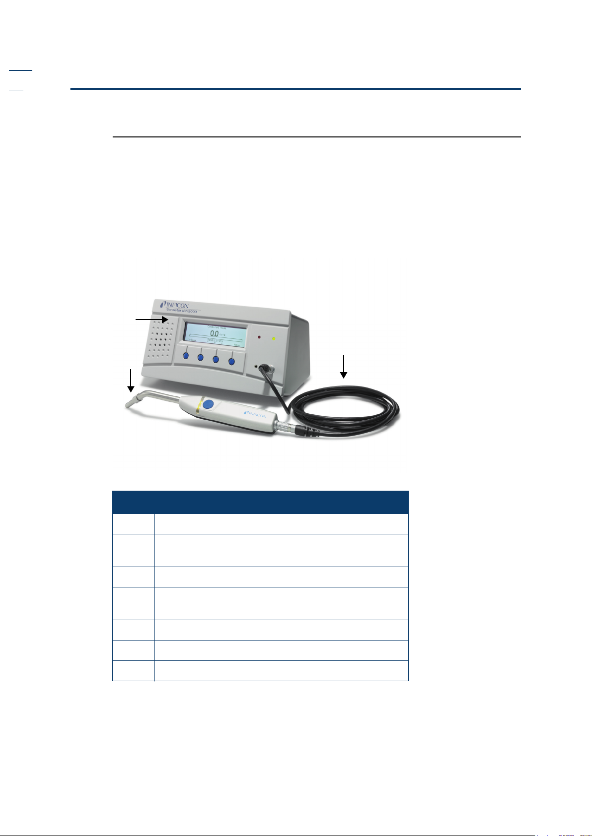
2.1 Sensistor ISH2000
Sensistor ISH2000 is equipped with a number of powerful functions making it very
easy to integrate in a semi or fully automatic test system. The functions range from
output of all necessary status signals and printer/communication port to an
advanced Active Probe Control system (APC). This makes the detector capable of
controlling advanced sample collecting devices down to simple test fixtures.
Fig 2-1. The desktop model consists of seven parts.
1
3
2
Item Description
1
2
3
4
5
6
7
Detector unit
Hand Probe P50 (shown) or Active Probe with
sensor
Probe cable C21
Power cable (the power cable is country specific
and may differ)
User manual (not shown)
User manual CD (not shown)
Product return form (not shown)
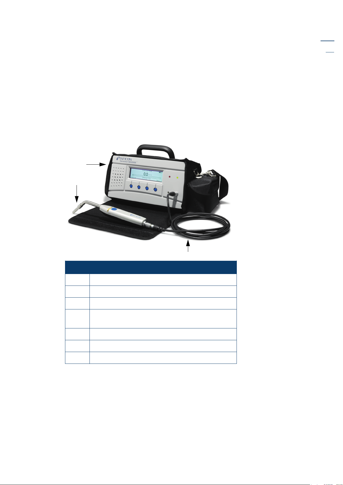
2.2 Sensistor ISH2000C
The battery operated model, Sensistor ISH2000C, has all the Sensistor ISH2000
features apart from the APC system. This means that only passive probes (for
example Hand Probe P50) can be used. This is due to power management control.
4 OP-Sensistor ISH2000-EN-201203
Page 7
Hydrogen leak detector Sensistor ISH2000 - Operating Instructions
The battery, a Li-ion battery at 14.8 V, can not support the current required to
operate external probes.
On the display (in Detection and Analysis Mode) a symbol in the upper right corner
shows the battery charge status. Sensistor ISH2000C will operate for 14 hours on a
fully charged battery with screensaver and mute function. And 9 hours without
screensaver and mute function.
One hour charging will give about one hour of operating time. This can be done
when necessary, but it is important to regularly fully charge the battery.
Fig 2-2. The battery operated model consists of seven parts.
1
2
EN
Item Description
1
2
3
4
Detector unit
Hand Probe P50 (shown) or P50-Flex
Probe cable C21
Battery charger (the battery charger are country
specific and may differ, not shown).
5
6
7
User manual (not shown)
User manual CD (not shown)
Product return form (not shown)
2.3 Sensistor ISH2000P
The panel mount model, Sensistor ISH2000P, has identical features of the Sensistor
ISH2000.
The difference is that the Sensistor ISH2000 can be installed in the operator’s panel
or any other flat surface. Also it operates on +24 VDC. Mounting brackets and a
panel rubber seal are delivered with the detector. See “Sensistor ISH2000P
installation” on page 38.
3
OP-Sensistor ISH2000-EN-201203 5
Page 8
Hydrogen leak detector Sensistor ISH2000 - Operating Instructions
EN
Fig 2-3. The panel mount model consists of seven parts.
1
Item Description
1
2
3
4
5
6
7
Detector unit
Brackets (not shown)
Screws (not shown)
O-rings seal (not shown)
User manual (not shown)
User manual CD (not shown)
Product return form (not shown)
6 OP-Sensistor ISH2000-EN-201203
Page 9
Hydrogen leak detector Sensistor ISH2000 - Operating Instructions
3 Controls and connections
The controls and connections are discussed and shown in this chapter.
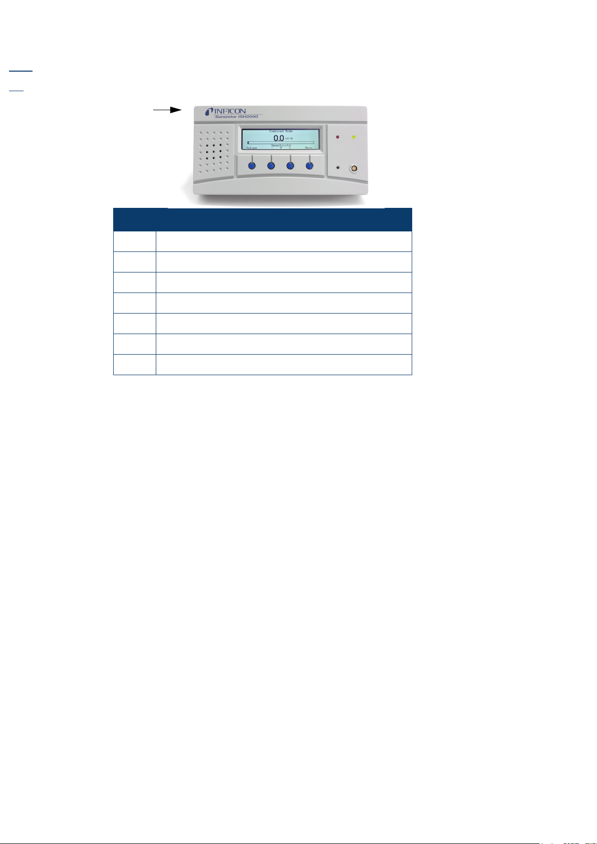
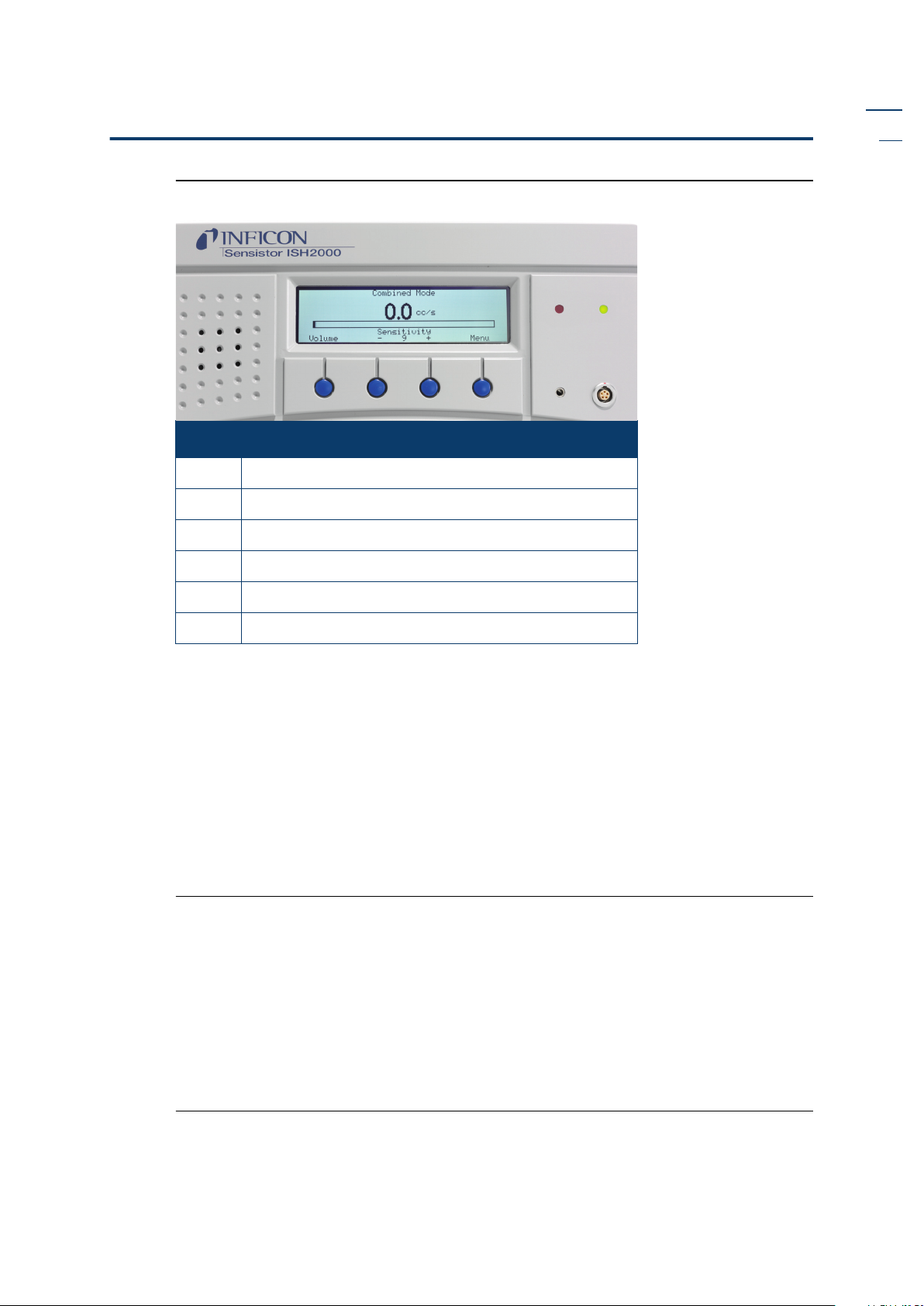
Fig 3-1. Sensistor ISH2000 controls and indicators.
1
2
3 3 3 3
Item Description
1 Display
2 Loudspeaker
3 Control push-buttons
4 Earphone socket
1
4
EN
6
5
5 Probe connector
6 LEDs
3.1 Display
The display shows:
• indicator bar in Detection Mode and the figures in Analysis Mode.
• seven main menus. Their positions are indicated on a horizontal scale. Change from
one menu to another using the < and > buttons.
• main menus have submenus, which are also indicated by horizontal scales and can
be selected using the < and > buttons.
• scales for setting numeric values, languages, etc.
• messages.
Sensistor ISH2000C:
• A battery status indicator in the upper right corner.
3.2 Push-buttons
The functions of the push-buttons are shown at the lower edge of the display. In this
manual the buttons are numbered, from left to right, 1, 2, 3, and 4. The push-buttons
are used to:
• Change from one menu item to another using the < and > buttons.
• Press Enter to move down to the nearest submenu.
• Press Save to save the set value.
• Press Undo to restore the previously set value.
• Press Esc to move up to the nearest higher level(s).
OP-Sensistor ISH2000-EN-201203 7
Page 10
Hydrogen leak detector Sensistor ISH2000 - Operating Instructions
EN
3.3 LEDs
The two LEDs indicate the status of the instrument as follows:
• Green flashing slowly, during warming up phase.
• Green fixed light indicates that instrument is ready and hydrogen signal is below
Reject Level limit.
• Red fixed light together with Reject on display means the instrument has detected a
leak larger than the set Reject Level limit.
• Red flashing rapidly, check message on screen. (See “Trouble-shooting” on
page 42.)
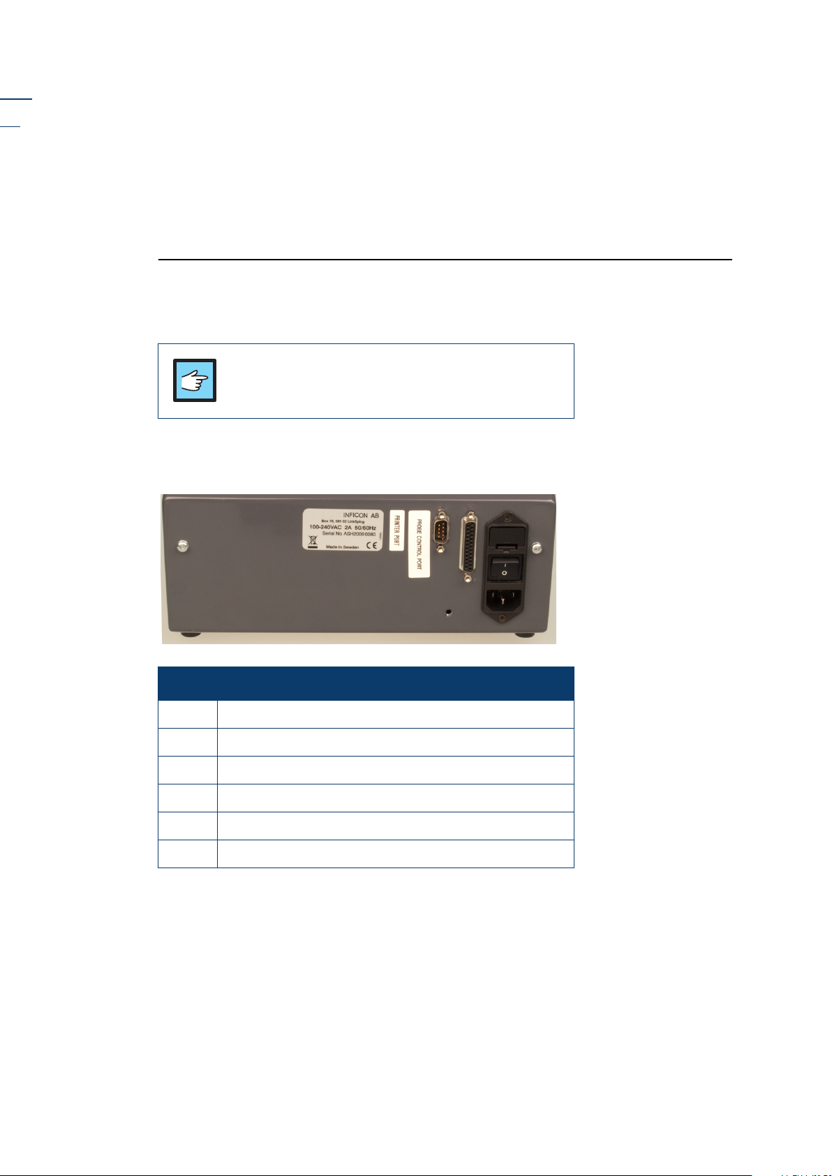
3.4 Ports and connections
The ports and connections are shown in Figure 3-2 below.
NOTICE!
Always connect all four wires to the Power connector to
24VDC in order to operate.
Sensistor ISH2000
Fig 3-2. Sensistor ISH2000 ports and connections.
Rear View
Item Description
1 Printer port
2 Probe control port
3 Fuse
4 Power switch
5 Power input, 100-240 VAC
6 Screw hole for mounting plate
6
3
3
1
1
2
2
4
4
5
5
6
8 OP-Sensistor ISH2000-EN-201203
Page 11
Hydrogen leak detector Sensistor ISH2000 - Operating Instructions
Sensistor ISH2000C
Fig 3-3. Sensistor ISH2000C ports and connections.
Sensistor ISH2000C Rear View
Item Description
1 Power switch
2 Printer port
3 Battery charger
4 Screw hole for mounting plate
EN
1
2
4
3
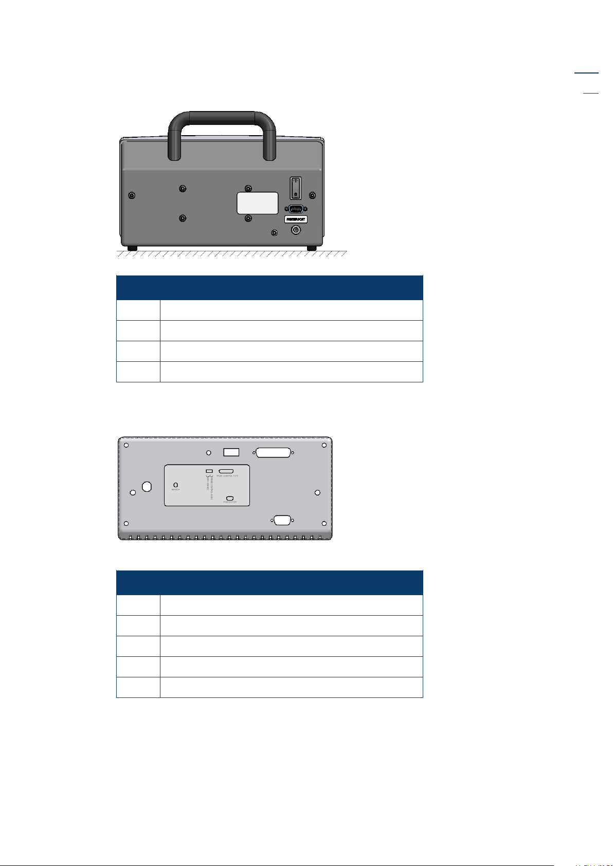
Sensistor ISH2000P
Fig 3-4. Sensistor ISH2000P ports and connections.
1
Sensistor ISH2000P Rear View
Item Description
1 Probe connection
2 Ground screw
3 Power connector
4 Probe control port
5 Printer port
3
2
4
5
OP-Sensistor ISH2000-EN-201203 9
Page 12
Hydrogen leak detector Sensistor ISH2000 - Operating Instructions
EN
4 Precautions
Read this user manual carefully before using the instrument. Hydrogen Leak
Detector Sensistor ISH2000 is extremely selective. Only Hydrogen Sulphide
(extremely toxic) gives a comparable response to hydrogen.
4.1 When working with gas
The normal risks associated with working with all compressed gases must be
considered.
WARNING!
Pure hydrogen is a flammable gas. Only use
ready-made Hydrogen Tracer Gas of 5%
Hydrogen in Nitrogen. This is a standard
industrial gas mixture used in various industrial
applications.
Note: Whenever the word Hydrogen is used in this
manual it implies that the hydrogen gas is safely
mixed with Nitrogen in the proportions 5% H2 95% N2.
WARNING!
Since the tracer gas mix contains no oxygen,
releasing large amounts of gas in a confined
space may lead to asphyxiation.
WARNING!
Compressed gases contain a great deal of stored
energy. Always carefully secure gas bottles
before connecting pressure regulator. Never
transport gas bottle with the pressure regulator
fitted.
Before connecting tracer gas: confirm that the connectors or test object is designed
for working at the test pressure.
WARNING!
Pressurising objects at too high pressures can
result in a burst object. This in turn can result in
serious injury or even death.
Never pressurise objects that have not
previously been burst tested or otherwise
approved for the chosen test pressure.
Note: INFICON AB can not take any responsibility for the consequences arising from the
inappropriate use of certain test pressures.
10 OP-Sensistor ISH2000-EN-201203
Page 13
Hydrogen leak detector Sensistor ISH2000 - Operating Instructions
Pressure shocks might cause strong sounds which can cause impairment of hearing.
Check that all relevant legislation and safety standards are complied with before
putting Sensistor ISH2000 into service.
4.2 Hydrogen Tracer Gas for leak detection
When pure hydrogen gas is released in air its flammability range spans from 4% to
75% of hydrogen in air. Below 4% there is insufficient chemical energy available for
a flame to occur. Above 75% hydrogen there is not enough oxygen left to support a
flame.
When, for example, a mixture of less than 5.5% hydrogen in nitrogen mixes with air
there is not sufficient energy to support a flame, irrespective of the ratio of air-togas.
When a mixture of more than 5.5% hydrogen in nitrogen is released into air there is
a region of ratios of air-to-gas where the mixture is flammable. When, for example,
a mixture of 10% hydrogen in nitrogen mixes with air there is still very little energy
available. Only in exceptional circumstances can a flame be self-supporting.
However, such mixtures cannot detonate.
WARNING!
Hydrogen/nitrogen mixtures containing
approximately more than 15% hydrogen can
detonate when mixed in certain proportions
with air.
EN
NOTICE!
Never make your own mixtures. Only use readymade mixtures or use a certified hydrogen/
nitrogen mixture mixer installed by your gas
supplier.
4.3 Interferences
Most tracer gas methods suffer from some sort of interference. Either the detector is
sensitive to other gases or vapors, or there are other sources of the gas present to
which the detector is sensitive.
Some examples of possible hydrogen sources:
• Engine exhaust
• Battery charging stations
• Cigarette smoke
• Breathing air
• Human flatulence
• Scratching on aluminum surfaces
OP-Sensistor ISH2000-EN-201203 11
Page 14

Hydrogen leak detector Sensistor ISH2000 - Operating Instructions
EN
5 Working principle
5.1 Gas Sensor Technology
The Sensistor ISH2000 leak detector is using an extremely sensitive hydrogen gas
sensor based on a microelectronic field effect transistor (MOS-FET).
The gas sensitivity appears when hydrogen absorbs into the sensor through a metal
alloy (metal hydride) layer.
Only hydrogen can diffuse into the metal and this makes the sensors practically
insensitive to other substances that do not contain free hydrogen molecules.
The signals from the sensors are processed by a microprocessor which also controls
the sensor temperature with high accuracy, and other sensor diagnostics in order to
ensure perfect functionality. It also automatically compensates for background gas.
5.2 Condition for leak detection
To use the leak detector the test object must be filled and pressurized by tracer gas
(95% N
welding gas of industry quality, easy to obtain at low cost. The generic name is
Forming Gas. Appropriate gas filling equipment can be obtained from the leak
detector supplier.
/ 5% H2) to get a gas flow through the leak. The tracer gas is a standard
2
Be careful of how tracer gases are handled after use. Released tracer gas
contaminates the surrounding air with hydrogen and can complicate the following
measurements for a time. Ensure that the tracer gas is ventilated away from the
target area, preferably to the outside of the building.
5.3 Leak detection modes
The detector operates in three modes:
• The leak locating mode (Detection Mode), mainly used for detecting and locating
leaks but not quantifying them.
• The hydrogen measurement mode (Analysis Mode) measures the concentration of
hydrogen.
• The Combined Mode, (default mode) which is a combination of Detection and
Analysis mode.
The Detection Mode operates continuously while the Analysis Mode determines the
hydrogen concentration (and calculates a corresponding leak rate) in a step
measurement. Detection Mode gives no numbers. It therefore needs no actual
calibration. The sensitivity of the sound signal and the moving bar on the display is
set manually or automatically, see below.
When using the instrument in Analysis Mode, it must be calibrated as described. See
“Calibrate the leak detector” on page 15 in order to give correct figures.
12 OP-Sensistor ISH2000-EN-201203
Page 15

Hydrogen leak detector Sensistor ISH2000 - Operating Instructions
6 Operating the detector
6.1 To Detect leaks
If all you wish to do is to detect the presence of a leak, that is, find out whether there is
a leak or not, then use the Detection Mode (or use the detection bar in Combined
Mode). The definition of Leak/No Leak will then simply be ”A leak is a leak when it can
be detected by the detector, set to a specific sensitivity”.
To set up:
The operation in Detection Mode is not quantitative. The audio and visual signal
will increase and decrease with the gas concentration. Therefore, there is no actual
calibration to be done, but rather a setting of the sensitivity to a desired level.
A typical set-up procedure for Detection Mode is:
• Set up a reference leak which corresponds to the smallest leak you wish to detect.
• Put the probe close to the reference leak and note approximately what reaction you
get (no reaction, small, medium, high, full scale) within the first few seconds.
• Set the sensitivity. This can be done permanently under the menu Detection Mode
Settings or temporarily as a Direct Sensitivity Adjustment on the display (unless
you have set this function to OFF under the Detection Mode Settings menu).
There is also an Auto ranging function which can be selected under the Detection
Mode Settings menu.
EN
Note: If the Detection Mode is used and the alarm function is required to be
activated at a particular calibrated level, then the unit must be calibrated in
accordance with the instructions, see “Calibrate the leak detector” on
page 15. The reason for this is that the alarm is based on the Analysis Mode
when the Detection Mode is displayed.
6.2 To Locate Leaks
Note: The Detection Mode (or use the detection bar in Combined Mode) is used
to locate leaks. This mode is semi-quantitative, that is, it gives an audio and
visual signal which increases as a leak is approached (a higher gas
concentration) and decreases as you move the probe away from the leak. It
does not display figures. In this mode of operation leaks can easily be detected
using a sensitivity which can be preset. See “Sensitivity” on page 25 and
“Direct Sensitivity Adjustment” on page 25.
Leaks can be located very accurately, even when there are other leaks nearby. If, for
example, you are trying to locate a leak on a product and the product has a major
leak, then you will get an audio signal as soon as the probe is placed close to the
product. When the probe is moved around and over the product, the signal will
increase as the probe approaches the leak. If the signal goes out of scale, simply
reduce the sensitivity setting to bring the signal within the scale. Working with the
sensitivity setting this way you will be able to locate multiple leaks that are in close
proximity to each other.
Note: Working inside a confined space such as, for example, a cabinet or a narrow
passage on a combustion engine there is a risk that the background
concentration accumulates to levels close to the upper detection limit of the
detector. In such case it will not be possible to locate leaks as easily as in open
spaces.
OP-Sensistor ISH2000-EN-201203 13
Page 16

Hydrogen leak detector Sensistor ISH2000 - Operating Instructions
EN
Hint: It is good practice to detect a leak, locate it, and immediately remove the probe
to avoid saturation. The probe is not damaged by the exposure but it will recover more
slowly. After excessive exposure it will be less sensitive for a short period of time.
6.3 To Quantify Leaks
The Analysis Mode (or use the analysis figures in Combined Mode) is used for
measuring the size of a leak (or the concentration of a gas sample). To be able to do
this measurement and obtain correct values, the instrument must first be calibrated
using the calibration function.
In the Analysis Mode the detector determines the gas concentration from the
change, as the probe goes from being exposed to background to being exposed to a
certain gas concentration. The detector does not continuously monitor the gas
concentration but takes just one reading instead. Another suitable alternative name
for this mode could be Sampling Mode. It is important to keep this in mind when using
the detector in this mode.
In Analysis Mode the probe should be moved directly from a background situation to
the test point. The size of the leak in PPM, or any other selected units, is shown on the
display. The probe can and should be removed from the measuring point as the
measured value steadies and remains on the display. The period during which the
measured value is displayed can be adjusted in the Analysis Mode Settings menu.
The leak detector operates in the range 0.5 - 2000 ppm H
giving linearity between 0.5
2
and 500 ppm. To obtain greatest accuracy over this range, follow the calibration
recommendation. See “Calibrate the leak detector” on page 17.
CAUTION!
• Do not open detector! Service of this equipment may only be carried out by service organisations authorised therefore by INFICON, Sweden.
• If the detector gets outer damage it must be controlled and repaired by service
organisation authorised by INFICON.
• Do not expose the probe to a hydrogen concentration higher than 0.1% when
the instrument is not put into operation, this might damage or destroy the probe
sensor.
• When the instrument is put into operation the sensor withstands temporary
exposure to hydrogen concentration up to 100%. Avoid long exposures to high
concentrations.
14 OP-Sensistor ISH2000-EN-201203
Page 17

Hydrogen leak detector Sensistor ISH2000 - Operating Instructions
7 Calibrate the leak detector
7.1 Introduction
The leak detector is the instrument and the probe together.
This section of the user manual consists of step by step examples about how to
calibrate the detector in the most common cases. For more about the calibration
routine see the reference section.
The instrument must be calibrated by using the integrated calibration function to
make sure it displays the correct values in Analysis Mode. After calibration the
instrument will show the correct measured values on the display in
The calibration parameters will be stored into the probe.
7.2 Calibration reference
There is a possibility to calibrate the detector by Reference Gas or Reference Leak.
A Reference Gas contains a well-defined concentration of Hydrogen gas in ppm
mixed by air or some inert gas. A Certificate will normal follow the gas bottles.
Reference Gas can be ordered from local gas suppliers.
A Reference Leak is a well –defined gas leak, and should be feed by same gas as
using in the detection test and with a gas pressure that is defined in the Reference
Leak certificate. Reference Leak can be ordered from the detector provider.
EN
Analysis Mode.
Choose a calibration reference size, as follows recommendations:
• Same or higher than the Reject Level (but maximum 10 times higher)
• in one of the following ranges:
5 to 400 ppm H2
1x10⁻⁵ to 4x10⁻³ cc/s (mbarl/s) defined for air
3 to 120 g/a defined for R134a
Please contact the provider of the detector for help to select optimal calibration
reference for your application.
7.3 Calibration procedure
Before calibration, the Reference Value in the Calibration Menu must be set. See “With
reference gas” and “With reference leak” below.
When calibrating, expose the probe to the background air then do the following
steps:
1. First Menu then Calibration/Calibrate/Enter.
2. Push the
3. Expose the probe for the reference gas/leak
The probe does not have to be exposed to the to the calibration gas during the
whole
The instrument only measures the change as the probe goes from the background
air to calibration gas.
Start button or push the probe button.
Calibration Time (the time set in the Calibration menu while the bar is moving).
While the calibration time bar is moving, the probe should be exposed to the
calibration gas or referenece leak. Then the display shows
sound signals. Save or repeat the calibration routine until you can save the
OP-Sensistor ISH2000-EN-201203 15
Detecting Gas and gives
Page 18

Hydrogen leak detector Sensistor ISH2000 - Operating Instructions
EN
calibration. If the calibration is not saved, the instrument will revert to the previous
value after one minute.
Note: You will need to repeat the calibration 2-3 times to get Calibration OK after
changing setup or probe.
• Allow at least 30 seconds between each calibration for best accuracy!
• If the message “
No Gas or Unstable Signal” is displayed repeatedly - go back to
Detection Mode and check functionality.
• If
Repeat Calibration is displayed then this means that the measured value
deviated more than 10% from the previous calibration. Repeat the calibration
procedure.
Also set the Analysis Unit to the same as the Reference Value. If you want to use
another unit you have to put a recalculation number into
describes the relationship between the different units.
7.4 Reference value with reference leak
When measuring leak flow you will, in normal cases, calibrate the detector with a
reference leak.
Set the
value can be found on the calibration certificate issued for the leak. Also set the
Reference Unit to the same unit as that used to express the leak rate of the reference
leak.
Reference Value equal to the calibrated flow of your reference leak. This
Correlation Value which
Example: Reference leak rate is 4.2E-5 mbarl/s.
1- Set Reference Value = 4.2E-05.
2- Set Reference Unit = “mbarl/s
Note: Feed the reference leak at the pressure stated on the calibration certificate. If
another pressure is used you must correlate the resulting flow and use this
value as
Note: The concentration of the reference leak should always during the calibration
Reference Value.
procedure be within the concentration range of 5 PPM - 400 PPM H
7.5 Reference value with reference gas
When measuring hydrogen concentration (instead of leak flow) in most cases you
will calibrate the detector to a reference gas with a known concentration.
Set the
This can be found on the certificate of analysis issued for the gas. Also set the
Reference Unit to the same unit as that used to express the leak rate of the reference
leak.
Example: Reference gas contains 10 PPM Hydrogen in synthetic air.
1- Set the
Reference Value equal to the Hydrogen concentration in your reference gas.
Reference Value = 10
2.
2- Set the Reference Unit = “PPM”
16 OP-Sensistor ISH2000-EN-201203
Page 19

Hydrogen leak detector Sensistor ISH2000 - Operating Instructions
8 Reference section
This section of the user manual consists of an in-depth explanation and additional
information, which completes the user manual with all relevant information.
8.1 Menu system
The menu system is designed as a tree structure similar to that used in mobile
telephones. The display shows all the levels when browsing down through the
menus so that you can always see exactly where you are.
Fig 8-1. Sensistor ISH2000 controls and indicators.
EN
1 2 3 4
To enter the menus, press
choose between main menus.
If no setting is made in a menu or its submenus within 60 seconds, the instrument
will revert to the Detection Mode/Analysis Mode.
Button functions
The buttons may change functions in different menues. Always read the text, just
above the buttons in the display, for the button functions.
All changes in values are valid only when saved using the
Use the
Undo button (button 1) to delete a change in value and revert to the
previous setting.
Use the
position
Esc button (button 1) to browse backwards through the menus to the start
Detection Mode/Analysis Mode.
To change quickly from
three times in succession.
8.2 Engineering format
Menu (button 4). Press < and > (button 2 and button 3) to
Save button (button 4).
Detection Mode to Analysis Mode or vice versa, press button 4
Some of the parameters of the detector are written in engineering format. This
format can represent a very wide range of numbers from very small to very large
numbers.
The following examples describes the format used in the detector:
1.00E+01 = 1.00 x 10
OP-Sensistor ISH2000-EN-201203 17
1
= 10
Page 20

Hydrogen leak detector Sensistor ISH2000 - Operating Instructions
EN
1.00E+00 = 1.00 x 100 = 1
1.25E-02 = 1.25 x 10-2 = 0.0125
8.3 Change Test Mode
Choose the measuring method you will use in the menu Change Test Mode. There
are three different methods to choose:
• Analysis Mode
• Detection Mode
• Combined Mode
See Reference section for a description of the functions.
8.4 Calibration
Calibrate
The instrument must be calibrated by using the integral calibration function to
ensure it displays the correct values in
calibration the instrument will show the correct measured values on the display. The
calibration parameters will be stored into the probe.
Analysis Mode/Combined Mode. After
Calibration intervals
Calibration is a natural part of leak measurement and an important factor in quality
assurance. It is impossible to specify an exact requirement for the interval between
the calibrations because the applications for which the instrument is used can vary
considerably.
There will be some oxidation of the probe sensor, which reduces the sensitivity, if
the probe sensor:
• is not subjected to gas for a lengthy period or
• is exposed to a very small gas concentration (less than 10 PPM) with long
intervals between exposure.
If the instrument is subjected to a very large gas concentration over a long period, a
certain amount of insensitivity can occur directly afterwards. This saturation can
make it difficult to detect very small leaks. Therefore, make it a habit of removing
the probe from the measuring point as soon as the measured value is displayed. This
gives the detector an opportunity to recover.
Sensitivity too low for reject level
The Detector will warn if sensitivity of sensor is too low to safely detect a leak equal
to the set Reject Level limit. The warning can be ignored and calibration updated
and the CAL_CONF output will be set.
High signal! Check reference!
The Detector will warn if the calibration signal is unreasonably high. This can occur,
for example, if 5% tracer gas mix has been used instead of proper reference gas or if
the reference leak has an extra non-intentional leak. The warning can be ignored
and the calibration updated and the CAL_CONF output will be set.
18 OP-Sensistor ISH2000-EN-201203
Page 21

Hydrogen leak detector Sensistor ISH2000 - Operating Instructions
Sensor condition indicator
The indicator bar extends in length when the sensor is detecting reference gas. This
indicator can be used for an early warning as to when a sensor replacement will be
needed.
Fig 8-2. Sensor condition indicator.
The length of the bar shows the condition of the sensor. The bar will become shorter
if the sensor has lost some in sensitivity. The scaling of the indicator is not precise
enough to say at exactly what length the sensor must be replaced. You will learn
when this happens for your particular application. The instrument will also tell you
in clear text when sensitivity is too low. See further in the next section below.
EN
Calibration messages
Table 8-1. Different messages that can be displayed during calibration.
Message Explanation Remedy
Expose to background... Prepare the probe for
Detecting gas Gas signal is detected. Normal operation, gas
Repeat calibration Calibration was not
Calibration OK Calibration was within
No gas or unstable signal. No gas signal or no stable
calibration by holding it
in hydrogen free
background.
within 20% of last.
acceptable limit.
signal detected during
calibration.
Signal when reference
gas is shut off. Happens
for reference gas only.
-
exposure can be
interrupted.
Wait 30 s and calibrate
again.
Press Save (button 4) to
store calibration in
memory.
Check reference. Gas
valve may be shut.
Check that probe tip is
not clogged.
Background is higher
than reference gas
concentration. Improve
ventilation.
OP-Sensistor ISH2000-EN-201203 19
Page 22

Hydrogen leak detector Sensistor ISH2000 - Operating Instructions
EN
Message Explanation Remedy
Sensitivity too low for
Reject level
High signal! Check
reference!
Note: If calibration fails you can still use the instrument. Last valid calibration
parameters will be used. You should, however, check that the instrument
reacts to the reference.
Reference Value
Your reference should have a concentration or flow equal to or slightly above what
you want to measure. See the examples below for specific recommendations.
Sensitivity of sensor is too
low to guarantee correct
response to a gas flow or
concentration equal to
the Reject level. The most
likely reason is that
sensor is too old.
Reference signal is
abnormally high.
Check reference. Gas
valve may be shut.
Check that probe tip is
not clogged.
Check setting of Reject
Level.
Replace sensor if problem
remains.
Check that reference gas
mix is not replaced with
tracer gas mix.
Check condition of
reference.
Check that reference leak
connections has no leaks.
Example for reference gas:
• Reject level is set at 8 PPM
• For good accuracy, use a reference gas between 5-400 ppm hydrogen.
• 8 PPM hydrogen in synthetic air will give best results.
Example for reference leak
• Reject Level is set at 2.0E-4 atm. cc/s
• For best accuracy reference leak within 2.0E-4 - 2.0E-3 atm cc/s.
• A reference leak calibrated to 2.0E-4 atm. cc/s will give best accuracy.
Reference Unit
The Reference Unit is set in the Calibration menu. Select PPM, cc/s, cc/min, SCCM, g/a,
oz/yr, mbarl/s, mm3/min, Pa m3/s or Custom. When you select Custom you can enter
any unit as long as it contains a maximun of 12 characters.
Calibration can be performed with:
• a known hydrogen concentration
• a known flow leak
The following characters can be used: Upper and lower case Roman letters, the
numbers ü,
ü, Å, Ä,Ö, å,ä,ö,%,/,(,),and - (dash).
Note: The space (““) is not supported. The leak rate unit string will be cut short at
the first space found. See “Engineering format” on page 17.
Calibration Time
The calibration time decides how long time the detector looks for a reference signal
before giving up. If the calibration is set to, for example, 6 seconds the detector will
20 OP-Sensistor ISH2000-EN-201203
Page 23

Hydrogen leak detector Sensistor ISH2000 - Operating Instructions
record the maximum signal during 6 seconds after that the operator (or external
hardware) orders a calibration.
It is very important that all delays in gas exposure as well as reaction time of sensor
are taken into consideration when setting the calibration time. Calibration will not
be correct if the maximum signal comes after that the calibration time has
terminated.
This is also the timeout of the Calibration line in an APC program.
Minimum calibration time
This parameter sets the lowest possible Calibration Time that can be set under the
Calibration menu. Default is 5 seconds.
Minimum calibration time should be set to safeguard so that the following two requirements are fulfilled:
1 The hydrogen from the reference leak or gas line must reach the sensor before
end of calibration time.
2 The sensor must have time to reach its maximum signal before end of
calibration time.
Setting
• Calibration will fail if calibration time is set too low.
• Calibration might pass but be incorrect.
Min Calibration Time too low will have the following effects:
EN
Setting a high
Min Calibration Time will have the following effects:
• Calibration takes longer time than necessary.
• Calibration gas consumption is higher than necessary.
NOTICE! Correct calibration is an essential
parameter in quality testing. We, therefore,
recommend that careful consideration is paid to
setting an appropriate
will inhibit personnel, lacking detailed
knowledge about calibration, from jeopardising
quality by setting a too short
Password protected calibration
If desired, the calibration can be set under the general password to prevent the
operator from calibrating by mistake. In this case you will have to enter the
password to start the calibration routine. Setting password protection on calibration
is done in the General Settings menu. Note that you must also set a password. The
instrument is delivered with no password set.
8.5 Detection Mode Settings
In Detection Mode, the signal is displayed in the form of a bar. The length of the bar
varies with the gas concentration.
Min Calibration Time. This
Calibration Time.
To detect leaks
If all you wish to do is to detect the presence of a leak, that is, to find out whether
there is a leak or not, then use the Detection Mode. The definition of Leak/No Leak
will be ”A leak is a leak when it can be detected by the detector, set to a specific
sensitivity”.
OP-Sensistor ISH2000-EN-201203 21
Page 24

Hydrogen leak detector Sensistor ISH2000 - Operating Instructions
EN
To set up:
The operation in Detection Mode is not quantitative. No figures are given but the
signal is still increasing and decreasing with gas concentration. Therefore, there is
no actual calibration to be done, but rather a setting of the sensitivity to a desired
level.
A typical set-up procedure for the Detection Mode is:
• Set up a reference leak which corresponds to the smallest leak you wish to
detect.
• Put the probe close to the reference leak and note approximately what reaction
you get (no reaction, small, medium, high, full scale) within the first few
seconds.
• Set the sensitivity. This can be done permanently under the menu
Detection Mode
or temporarily as a Direct Sensitivity Setting on the display (unless you have set
this function to OFF under menu Sensitivity Settings. There is also an Auto
ranging function which can be selected under the
Detection Mode Settings
menu.)
If the sensitivity is set very high, you may find the baseline annoyingly unsteady.
Note: If the Detection Mode is used and the alarm function is required to be
activated at a particular calibrated level, then the unit must be calibrated. The
reason for this is that the alarm is immediately based on the Analysis Mode
when the Detection Mode is displayed, due to inaccuracies in the Detection
Mode signal.
To locate leaks
Detection mode is semi-quantitative, that is, it gives an audio and visual signal
which increases as a leak is approached (a higher gas concentration) and decreases
as you move the probe away from the leak. It does not display figures.
In this mode of operation leaks can easily be detected using a sensitivity which can
be preset. Leaks can be located very accurately, even when there are other leaks
nearby.
If, for example, you are trying to locate a leak on a refrigerator condenser tubing
and the tubing has a major leak, then you will get an audio signal as soon as the
probe is placed close to the condenser tubing. When the probe is moved around
over the condenser, the signal will increase as the probe approaches the leak. If the
signal goes off the scale, simply reduce the sensitivity setting to bring the signal
within the scale. By working with the sensitivity setting in this way, you will be able
to locate multiple leaks that are in close proximity to each other.
Do not expose the probe to more gas than is necessary, because it will slowly
saturate with time. It is good practice to detect a leak, locate it, and immediately
remove the probe to avoid saturation. The probe is not damaged by the exposure
but it will recover more slowly. After excessive exposure it will be less sensitive for a
short period of time.
Background compensation
There is always some hydrogen gas in the background. In fresh air this is as low as
0.5 ppm (parts per million).
Sensistor ISH2000 actively adjusts itself to the background. This is done
automatically at start-upand thereafter, it slowly adapts itself to slow variations in
the background concentration. By adjusting slowly (minutes) it avoids mistaking an
actual leak for an increased background and vice versa. Therefore, a sudden rise in
22 OP-Sensistor ISH2000-EN-201203
Page 25

Hydrogen leak detector Sensistor ISH2000 - Operating Instructions
background concentration will be detected. However, if the concentration remains
constant it will be gradually cancelled out over a period of several minutes.
For example, if the background concentration for some reason should suddenly rise
to 10 ppm H
, then the detector will give a corresponding signal which will very
2
slowly decline to zero. If you thereafter expose the probe to a leak which gives rise
to another 10 ppm H
, then the detector will give essentially the same signal as if
2
there were no background concentration.
Sensitivity
Sensitivity of audio signal and signal bar in Detection Mode.
Note: This does not affect the Analysis Mode.
Auto Range
Set this parameter to ON for auto ranging of sensitivity in Detection Mode. Sensitivity
will decrease two steps if the signal reaches full scale. Sensitivity is restored to
selected Sensitivity (See “To locate leaks” on page 22) when signal returns to zero.
Direct Sensitivity Adjustment
Setting this parameter to OFF will remove the sensitivity adjustment from the
Detection Mode display. Sensitivity can still be adjusted in the Sensitivity Settings menu
after entering password (if set).
EN
Note: The sensitivity setting only affects the Detection Mode.
Audio Threshold
Makes it possible to lower the sound to a set level in Detection Mode. The level is in
% of full Detection bar.
Reject Indicator
Makes it possible to show (not shown) the indication Reject in Detection Mode.
Audio Ready Pulse
This sets the standby sound to a silent or or pulsating tone.
8.6 Analysis mode
In Analysis Mode the measured value is displayed in figures. The default unit is in PPM
but it is possible to choose other units, See “Default parameters” on page 40.
To analyse leaks
The Analysis mode is used for measuring the size of a leak (or the concentration of a
gas sample). To be able to do this measurement and obtain correct values, the
instrument must first be calibrated using the calibration function.
In the Analysis mode the detector determines the gas concentration from the
change, as the probe goes from being exposed to background to being exposed to a
certain gas concentration. The detector does not continuously monitor the gas
concentration but takes just one reading instead. Another suitable alternative name
for this mode could be Sampling Mode. It is important to keep this in mind when
using the detector in this mode.
OP-Sensistor ISH2000-EN-201203 23
Page 26

Hydrogen leak detector Sensistor ISH2000 - Operating Instructions
EN
In Analysis mode the probe should be moved directly from a background situation
to the test point. The size of the leak in PPM, or any other selected units, is shown
on the display. The probe can and should be removed from the measuring point as
the measured value remains on the display.
The period during which the measured value is displayed can be adjusted in the
Display Settings menu.
Reject level
Threshold level for Reject decisions. When this level has passed Reject it will be
indicated by audio and LED signals Reject on APC-bus high.
Note: The frequency of the acoustic signal in Analysis Mode is controlled by Reject
Level
frequency despite the actual signal strength.
Correlation Value
Correlation Value is used when it is necessary to correct the relation between the
detector signal and the displayed number. This might be necessary when you want
to display leak rate unit other than the calibrate leak rate unit.
Analysis Unit
The Analysis Unit is a text string with a maximum of 12 characters. It is not involved in
any calculations.
. A signal equal to the Reject Level will always give the same audio
The following letters can be used; Upper and lower case English letters, the numbers
0 to 9, Å, Ä, Ö, å, ä, ö, %, /, and -. Space (““) is not supported. The string will be
shortened after the first space found.
Multipoint Analysis
Summing up of the analysis result. A fixed or moving number of measurements with
a maximum 25 measurement points can be chosen.The instrument must be in
Analysis Mode or Combined Mode for this function to be active. Toggle the Mode
function for hand probe, however, APC is inactivated with Multipoint Analysis.
To use Multipoint Analysis
If a fixed number of measurement points is used then measure according to the
following steps:
1. Push the probe button to begin the first measurement.
2. Place the probe on the measurement place during the time the staple moves. The
instrument registers the results.
3. You might need to wait until the next measurement. The instrument signals-
4. Repeat the procedure for the next measuring point.
When all measurements are made the sum of all leaks is shown. If the sum of all
leaks is greater or the same as the Reject Level then REJECT is shown. If the sum of
all leaks is under the Reject Level then ACCEPT is shown. And if the sum of all leaks
is greater than Reject Level before all measurements are made then REJECT is
shown.
Wait.
Use < > to view individual measurements.
To begin a new measurement action or to stop a current measurement push the
probe button and hold the button for a moment.
24 OP-Sensistor ISH2000-EN-201203
Page 27

Hydrogen leak detector Sensistor ISH2000 - Operating Instructions
It is possible to measure or search in (Combined Mode) for a leak withut registering
the measurement. The measurement value registers only when the staple moves
(Multipoint Analysis Time).
If a dynamic number of measurement points is selected the do the measurement in
the following teps:
1. Push the probe button to begin the first measurement.
2. Place the probe near the measurement point during the time the staples move
(Multipoint Analysis Time).
3. You might need to wait until the next measurement. The instrument signals-
4. Repeat the procedure for the next measuring point.
5. When you sum up all the measurements push and hold on the probe button a
short time.
Multipoint Analysis Time
Set the time for each measurement.
Min Presentation Time
Signal values in Analysis Mode will never be presented shorter than this time. Values
are, however, always presented until the signal has recovered. The default value is 1
second, but values from 0 - 120 seconds can be used.
EN
Wait.
Display Threshold
Hides all measurements under a set % of Reject Level.
Audio Threshold
Instrument is silent under a set % of Reject Level.
Reject Indications
There are three choices of Reject Level indications except the LEDs indication:
• Flashing screen
• Chopped audio signal
• Combination of indication 1 and 2.
Show Reject Level
Shows the Reject Level value on the display.
Audio Ready Pulse
This sets the standby sound to a silent or or pulsating tone.
8.7 APC Settings
APC is an abbreviation for Active Probe Control. The APC function is for the control
of an active probe that has a built-in alarm, valves or pumps via Probe Control Port.
OP-Sensistor ISH2000-EN-201203 25
Page 28

Hydrogen leak detector Sensistor ISH2000 - Operating Instructions
EN
Different probes require controls therefore, it is possible to download different
drive routines for the instrument from a PC.
There is a possibility to adapt how to measure by adjusting the timers and Purge
Level.
Probe Type
Select the connected probe. Choose between “Hand Probe” and another probe
driver installed from the disc delivered with active probe (if ordered).
APC Time A-D
Adjustable timer used by the APC system. Select a APC timer and press “Enter” to
display specific use of this timer. APC timer can be used for general purposes in a
custom APC program.
Purge Level
Signal level controlling the Purge_Level APC Triggers. Standard probes that support
active sampling use the
high gas signals.
Setting
cycle times for those probes.
Purge Level for fast interruption of sampling that result in
Purge Level equal to, or just above, Reject Level will give the fastest possible
Quick purging also enhances signal repeatability.
Note: Purge level interrupts active sampling of APC probes. This means that higher
signals will be underestimated as the sensor is purged before full signal has
developed. .
Reset Signal
Reset the sensor level in Analysis mode and Detection mode.
8.8 Display Settings
This section describes the different display settings of the Sensistor ISH2000.
Contrast
Contrast level of display. Higher value gives higher contrast. The contrast may need
adjustment if ambient temperature changes.
Brightness
Brightness of the display lamp. A lower brightness value saves energy and prolonges
the lamp.
Invert Colors
Change the black to white and white to black. Useful in a dark environment to keep
a high readability.
Screen Save Timeout
Display lamp will dim to half brightness if instrument is left idle for the number of
minutes set by this parameter. The screen save timeout can be set between 1 and 60
26 OP-Sensistor ISH2000-EN-201203
Page 29

Hydrogen leak detector Sensistor ISH2000 - Operating Instructions
minutes, the function is deactivated if set to OFF. The display lamp will return to the
set brightness if any of the display buttons are pressed, if a gas signal is detected or
an instrument error is detected.
8.9 General settings
This part describes the general settings of the Sensistor ISH2000.
Language
The Sensistor ISH2000 user interface contains the following languages:
• English
• French
• German
• Italian
• Spanish
• Swedish
Measure/Print Button
Setting this parameter to ON displays Measure or Print above the button 1. Measure
will be displayed for an APC-Probe or
initiate a sample cycle. Pressing
measurement to the printer port.
EN
Print for a Hand Probe. Pressing Measure will
Print will send the values from the hand probe
Probe Button
This is for setting the different functions with the probe button. These functions are
as follows:
• Toggle Mode-makes it possible to switch between Analysis mode and Detection
mode.
• Zero detection signal-in Analysis mode and Detection mode.
• Measure/Print-makes it possible to initiate sample cycles or send the values from
the hand probe measurement to the printer port.
• Probe Lamp-makes it possible to turn on and off the Probe Lamp.
Probe Lamp
Makes it possible to have the Probe Lamp on even if the other Probe Button
function is chosen.
Change Password
The user password is a text string (max 12 alphanumerical characters) used to lock
critical parameters. Setting password to an empty string (no characters) means that
no password is needed to modify the critical parameters. The default is no password
(“”).
Contact INFICON AB if you have lost your user password. If the
Calibration parameter is set to ON you will be prompted for a password when starting
a calibration.
Password Protected
Note: Setting Password Protected Calibration to ON has no effect if no password is set.
Note: APC controlled calibration can be started from the bus in both cases.
OP-Sensistor ISH2000-EN-201203 27
Page 30

Hydrogen leak detector Sensistor ISH2000 - Operating Instructions
EN
Audio Base Frequency
This sets the lowest audio base frequency tone in Analysis and Detection Mode.
Set Clock
Real time set as hh:mm:ss. Hours and minutes can be adjusted. Seconds will
automatically be set to 00 when hours and minutes have been set. Clock runs even
when detector is disconnected from the power supply.
Set Date
Real Time Clock date set as YY-MM-DD. Clock runs even when detector is
disconnected from the power supply.
Printer Port
The Sensistor ISH2000 is equipped with a serial (RS232) printer port. See “Printer
port” on page 33.
Info
Contains information about software versions, Serial number, and Internet contact
information.
8.10 Service Settings
The Service Mode is reached by starting the instrument and at the same time hold
the right button down on the panel. After start a new main menu called Service
Settings will appear.
Show Password
Shows the chosen password in case the customer has forgotten the password.
Contact INFICON AB to have the code sent to you. See the web address under the
section-Info.
Probe System Reset
Reset all parameters into the probe to default settings. Contact INFICON AB to have
the code sent to you. See the web address under the section-Info.
System Reset
Resets all parameters to default settings. Contact INFICON AB to have the code sent
to you. See the web address under the section-Info.
Detector Signal Level
The Detector Signal Level is the level which the sensor is considered to have recovered
from the last gas signal. It decides when the DET_SIGNAL output will come on. this
signal can be used to block the start of a calibration or new test cycle in semi and
fully automatic testers.
IF DET_SIGNAL is high then this means that the sensor has detected hydrogen and
has not yet recovered.
Detector Signal Level can be adjusted in the Service Settings menu. You can increase
Detector Signal Level if you have many small disturbing signals. A high setting of
Detector Signal Level gives better tolerance to “noise” gas signals at the expense of
28 OP-Sensistor ISH2000-EN-201203
Page 31

Hydrogen leak detector Sensistor ISH2000 - Operating Instructions
accuracy. A low setting gives best accuracy but lower tolerance for “noise” gas
signals. The
20%.
NOTICE! Increasing the Detector Signal Level may give poorer accuracy.
Detector Signal Level is set as 1 to 100% of the Reject Level. Default is
Trigg Level
Upper Limit setting for Peak hold in analysis mode.
Minimum Calibration Time
Lower limit setting for the timer which is used during calibration. Contact INFICON
AB to have the code sent to you. See the web address under section-Info.
Battery Mode
Selection of battery power. Only used to adapt software for the battery model.
Number of Significant Digits
Choice of a number of significant numbers in Analysis and Combined Mode. It is
used when a more exact measurement is needed. A good control of the
environment and calibration is required to be useful. Contact INFICON AB to have
the code sent to you. See the web address under section-Info.
EN
Debug Mode
This mode is used during service and software development.
Service Mode
This mode contains useful information to analyse the gas sensor behavior. If the
instrument starts in the Service Mode then it is possible to reach APC Service Mode.
Under APC Service Mode is useful information to check timers, I/O on the Probe
Control Port, and other.
8.11 Combined Mode
In Combined Mode the bar and the sound in Detection Mode is combined with the
figures in
and the measured value is displayed in figures.
The loud speaker sound follows the Detection Mode signal.
Note: After a system reset the default mode is Combined Mode.
When you have located the leak then you can measure its size in the following way:
1. Remove the probe from the leak.
2. Wait until 0.0 appears on the display
3. Then put the tip of the probe on the leak.
Analysis Mode, this means that at the same the signal is displayed as a bar
8.12 Probe
The hand probe P50 is a non-sniffing probe. Gas analysis takes place in a sensor that
is in the tip of the probe. The probe is equipped with a function button, indicator
lamps, and lighting. Also the probe can be ordered with a flexible neck.
OP-Sensistor ISH2000-EN-201203 29
Page 32

Hydrogen leak detector Sensistor ISH2000 - Operating Instructions
EN
During operation the heat of the probe tip is 50ºC
Note: There are a variety of different probes that can be connected to the Sensistor
ISH2000. When using an active probe please refer to the respective probe
manual.
Changing the Probe
After attaching a probe the Sensistor ISH2000 needs to stabilize, and the green LED
should blink. If it does not, then there is a fault in the cable or the hydrogen sensor
inside the probe is faulty.
When the stabilisation period is over the green LED should stay on. Before using the
Sensistor ISH2000 the instrument needs to be calibrated. Repeat calibration after
one hour to achieve greatest accuracy.
Changing the Probe Tip
The probe tip is replaceable and is locked with a union nut. The union nut seals
against contact with moisture. If you are not sure about changing the probe tip
then we recommend that you send it to an authorized service center.
To change the probe tip do the following steps:
1. Turn off the instrument.
2. Loosen the safety nut with the appropriate tool (P/N 598-147) or with a 10 mm
wrench.
3. Remove the tip by hand. The o-ring creates some friction.
4. Remove the sensor by drawing it straight out.
5. Mount a new sensor. Make sure it is in correct position.
6. Observe the contact area between the probe pipe and the sensor. They should
contact each other.
7. Mount the union nut.
8. Tighten with a suitable tool.
8.13 Probe Control Port
The Sensistor ISH2000 is equipped with a parallel Probe Control port. This Probe
control port
supervising computer system, and for simple test fixture control.
Note: Battery operated model Sensistor ISH2000C does not have a Probe Control Port.
Pin configuration for the different detector models is described under Model
Specific Specifications below.
See “Sensistor ISH2000 specifications” on page 43 for electrical specifications.
See “Status signal patterns” on page 31 for signal patterns.
30 OP-Sensistor ISH2000-EN-201203
can be used for controlling active probes, feeding status signals to a
CAUTION!
The Probe Control Port (25-pin D-type) on the
back of the instrument is not a computer or
printer port. Connecting a printer or any other
computer device may cause permanent damage
to the connected device.
Page 33

Hydrogen leak detector Sensistor ISH2000 - Operating Instructions
Probe Control Port Connector
The control port connector is a 25-pin female D-sub. Refer to Table 8-2 for the pin
configuration.
Table 8-2. Pin configuration.
Pin Type Signal name
1 - GND
2 - GND
3 - GND
4 IN IN_0
5 IN IN_1
6 IN IN_2
7 IN IN_3
8 IN IN_4
9 OUT CAL_CONF
10 OUT OUT_6
11 - GND
12 - GND
EN
13 - GND
14 OUT DET_ERROR
15 OUT LEAK_OUT
16 OUT DET_ON
17 OUT DET_SIGNAL
18 OUT DET_WAIT
19 OUT OUT_0
20 OUT OUT_1
21 OUT OUT_2
22 OUT OUT_3
23 OUT OUT_4
24 OUT OUT_5
25 OUT 24 VDC OUT
Status signal patterns
Table 8-3. Status signals for pin 14 - 18 (see “Pin configuration.” on page 31).
Signal Function
DET_SIGNAL Gas detected / Sensor not recovered.
DET_WAIT High during warm-up.
DET_ON High when detector is on.
LEAK_ALARM Leak above Reject Level detected.
DET_ERROR High if Probe, Sensor or Cable is broken.
OP-Sensistor ISH2000-EN-201203 31
Page 34

Hydrogen leak detector Sensistor ISH2000 - Operating Instructions
EN
DET_ERROR will go high for a short time (1-5 seconds) when the detector is switched
on. It will go low when the sensor has been checked.
In normal operation, DET_ERROR = HIGH means that there is a problem with the
sensor, probe, or cable.
DET_WAIT is high when instrument is in warm-up mode after switching on power.
Instrument will also go into warm-up if there is a temporary fault in the sensor or
sensor connection.
The timing of the status signals in relation to different events is described by the
following two examples:
Example: Input signals issued to control the APC system should have a pulse length
of at least 40 ms.
Example: Output signals switch with a cycle time of 20 ms (0.02 s). This is the cycle
time of the APC system.
Note: Not valid for battery operated version of Sensistor ISH2000.
After power on
Fig 8-3. Status signals after power on.
Power onPower off Warming up Detection or analysis
mode. No gas detected.
DET_ERROR
DET_ON
DET_WAIT
DET_SIGNAL
LEAK_OUT
When detecting a gas signal
Fig 8-4. Status signals when detecting a gas signal.
Gas signal
Purge level
Purge level
Reject level
Detector signal level
0 PPM
DET_SIGNAL
LEAK_OUT
PURGE_LEVEL Trig-
ger (APC)
32 OP-Sensistor ISH2000-EN-201203
Page 35

Hydrogen leak detector Sensistor ISH2000 - Operating Instructions
8.14 Printer port
The Sensistor ISH2000 is equipped with a serial printer port. This is the 9-pin D-type
connector. It is used for printer connection, RS232 commands and APC driver
installation.
NOTICE!
Always switch power off before disconnecting or
connecting any cable.
Connector pin configuration
The printer port is a standard 9-pin male D-sub. The connecting cable is a standard
9-pin file transfer cable (Null Modem Cable). For the pin configuration refer to Table
8-4.
Table 8-4. Pin configuration of the printer port.
Pin Signal Comments
1 (DCD) Not used
2 RD Received data
3 TD Transmitted data
4 (DTR) Not used
EN
5 SG Signal ground
6 (DSR) Not used
7 (RTS) Not used
8 (CTS) Not used
9 (CE) Not used
Only pin 2 (Received data), pin 3 (Transmitted data) and pin 5 (Signal ground) are
used. Refer to Figure 8-5 for the wiring diagram.
Fig 8-5. D9 Null modem cable wiring diagram
1
CD
2
RxD
3
TxD
DTR
4
SG
5
DSR
RTS
CTS
R1
6
7
8
9
D9 Female
Selectable printer types
Most PC-printers with serial interface can be connected to the 9-pin printer port.
Parallel (Centronics) interface printer can be used if connected through a serial to
parallel converter.
1
2
3
4
5
6
7
8
9
CD
RxD
TxD
DTR
SG
DSR
RTS
CTS
R1
D9 Female
The port can be set up for the following printer types: PC Printer and Data Dump.
No printer
OP-Sensistor ISH2000-EN-201203 33
Page 36

Hydrogen leak detector Sensistor ISH2000 - Operating Instructions
EN
Printer output disabled. Incoming communication is enabled. Sensistor ISH2000
listens for incoming data but will not print/send test results.
PC printer (with serial interface)
The PC Printer option can be used to print data on most standard PC printer with
serial interface. Parallel interface printers can be used if connected through a serial
to parallel converter (see below).
Note: The output format has been chosen to be as simple as possible to ensure that
most printers will accept it. Therefore, the printer output does not use any
flow control. This means that some printers may delay printing until the input
buffer is full or a pre-defined timeout has elapsed.
Table 8-5. Communication specifications.
Setting Value
Data rate 1200 baud
Data bits 8
Stop bits 1
Parity None
Flow control None
Note: Due to the large variety of printers available on the market, INFICON does not
take responsibility for the operation of a particular type of printer.
Printed data
The detector can print the following information:
1 Date and Time for Power on of detector.
2 Time of print.
3 Value of all gas signals above the Reject Level.
4 Test result: “Accept” or “Reject”.
5 Value of signal.
6 Result of calibration: “OK” or “Calibration Not saved”, Date and Time,
Parameter settings.
Printing of the current value can also be requested by an RS232 command (See
“Connector pin configuration” on page 33) or ordered manually by pressing
PRINT.
Table 8-6. Probe type determines information printed.
Probe type Data printed
Hand Probe P50 1, 2, 3, 4, 6
Counter Flow Hand Probe AP57 1, 2, 3, 4, 6
Sniffer Hand Probe AP55 1, 2, 4, 5, 6
Sampling Units AP29 ECO, AP33 1, 2, 4, 5, 6
Analysis data output
The Analysis Data Output option is intended for transferring test results to a
supervising computer system such as, for example, a PLC system.
Table 8-7. Communication specifications.
Setting Value
Data rate 9600 baud
34 OP-Sensistor ISH2000-EN-201203
Page 37

Hydrogen leak detector Sensistor ISH2000 - Operating Instructions
Setting Value
Data bits 8
Stop bits 1
Parity None
Flow control None
The data format for Analysis data output consists of nine ASCII characters. Seven
characters show the value in engineering format (See “Engineering format” on
page 17), one character shows the result of the test, and one character shows line
feed (LF).
Table 8-8. The character indicating the result of the test is one of the following.
Character Result of the test
A Accept. Previous test was below Reject Level limit.
R Reject. Previous test was above Reject Level limit.
P Rejected by Purging. Previous test was above purge limit
(and Reject level limit).
C Calibration approved. Previous cycle was calibration.
Calibration was approved.
EN
F Calibration failed. Previous cycle was calibration.
E Test interrupted by “Error” that occurred during cycle
(probe or sensor error etc.).
Example: 2.5E-04R (LF)
This example is a line feed (LF), R means that the test was above the Reject Level
limit, and the value was 2.5E-04.
For passive probes (for example P50 and AP57*) data is printed when a signal is
detected above
Measure Button menu.
Reject Level or when the print button is pressed. Activate this under
For active probe AP29, data is printed at end of measurement sequence.
Printing of the current value can also be requested by an RS232 command or
ordered manually by pressing
PRINT. See “Connector pin configuration” on page 33.
* A custom APC program setting the MEAS flag prints as AP55/AP29 ECO and an APC
program not using MEAS flag prints as P50.
Detection data output
The Detection Data Output option is intended for automated scanning of weld seams
etc.
Note: The Detection Data is expressed in arbitrary units. Detection Mode signal is not
affected by calibration!
Table 8-9. Communication specifications.
Setting Value
Data rate 9600 baud
Data bits 8
Stop bits 1
OP-Sensistor ISH2000-EN-201203 35
Page 38

Hydrogen leak detector Sensistor ISH2000 - Operating Instructions
EN
Setting Value
Parity None
Flow control None
The data format for Detection data output contains of ten ASCII characters. Nine
characters show the value in engineering format (See “Engineering format” on
page 17), and one character shows linefeed (LF).
The print time is 50Hz continuous streaming data.
Note: Data rate is 25Hz when Sensistor ISH2000 is running in Service Display Mode.
RS232 serial communication
The most commonly used Sensistor ISH2000 functions can be started/configured
over the RS232 interface.
Table 8-10. RS232 communication specifications.
Setting No Printer PC Printer
Data rate 115200 baud 1200 baud 9600 baud
Data bits 8 8 8
Data
Output
Stop bits 1 1 1
Parity None None None
Flow control None None None
RS232 interface commands
Table 8-11. Common used functions.
Command Header
Calibrate K
Measure M
Print Request N
Stop Measurement Q
Hand Probe R
Active Probe (Installed AP) S
Analysis Mode X
Detection Mode Z
Combined Mode Y
K = Calibration request
Starts calibration if the Sensistor ISH2000 has an active probe driver installed.
Sensistor ISH2000 answers with a "K" if an active driver containing a calibration
routine was found and "F" if the calibration APC sequence not found. Calibration
doesn’t start if Purge level is reached.
M = Measure Request
36 OP-Sensistor ISH2000-EN-201203
Page 39

Hydrogen leak detector Sensistor ISH2000 - Operating Instructions
The active test cycle defined by the APC driver starts. “M” is returned if the selected
driver supports active test. “F” (failed) is returned otherwise.
N = Print Request
Returns current analysis value.
Q = Set APC in stand by, (stop a measurement)
Returns a “Q”.
R = Activates probe 0 (built in P50 driver)
Returns an “R”.
S = Activates probe 1 (Installed probe driver)
Returns an “S”.
X = Shift State to "Analysis Mode"
Returns nothing.
Z = Shift State to "Detection Mode"
Returns nothing.
Y = Shift State to “Combined Mode”
Return nothing.
Supported parameters
Table 8-12. The following parameters can be downloaded to Sensistor ISH2000 in
Analysis and Detection mode.
EN
Parameter Header Data
Reject Level A n.nnE+nn
Correlation Value B n.nnE+nn
Analysis Unit C Text string (max 12 characters)
Analysis Unit CUx x=1 to 8, 1=PPM, 2=CC/S up to 8
Timer A D nnn*
Timer B E nnn*
Timer C F nnn*
Timer D G nnn*
Purge Level H n.nnE+nn
Reference Value I n.nnE+nn
Reference Unit J Text string (max 12 characters)
Reference Unit (Program settings) JUx x=1 to 8, 1=PPM, 2=CC/S
* entered as integer in 10’s of seconds, 1= 0.1s, 100 = 10s, 60000= 6000s
Transfer of parameters
Send parameters one by one; first send the specific header (for example “A”), then
wait until the RS232 transmitter unit has sent the data (approximately 20 ms), and
then send the data (for example “1.00E+01”). Data string must be ended with a
carriage return character, chr13 (dec).
Example: “CPPM” or “C PPM”, Carriage Return (chr 13). This sets Reject Level Rate
Unit to “PPM”.
OP-Sensistor ISH2000-EN-201203 37
Page 40

Hydrogen leak detector Sensistor ISH2000 - Operating Instructions
EN
Parameters can be sent in any order you like:
• If your data was received and correct, Sensistor ISH2000 immediately echoes
(sends back) the data.
• If you send a non existing header you will not receive anything.
• If the data could not be converted in the Sensistor ISH2000 you will receive the
string “CoEr”, (Conversion Error).
Note: Remember to use capitals for the header.
APC driver installation
APC drivers are installed in the detector from a PC. All active probes need a driver to
be installed before they can be used.
Note: Battery operated model Sensistor ISH2000 does not incorporate the APC
feature.
For driver installation you will need the following:
• APC Driver software. (Delivered with the probe.)
• File transfer cable. (Delivered with the probe.)
• PC computer with Windows 95 or later.
8.15 Sensistor ISH2000P installation
The panel mount model can be installed in the operator’s panel or any other flat
surface of your leak tester. Mounting brackets and panel rubber seal are delivered
with the detector. Refer to Figure 8-6.
CAUTION!
The detector should preferably be mounted on a
vertical surface. Tilting more than 30 degrees is not
recommended. Tilting more makes air circulation
poor resulting in increased temperature inside
detector. This will reduce contrast of display and
lifetime of lamp and electronic circuits.
NOTICE!
After installation verify that ambient
temperature is below 50ºC.
Fig 8-6. Panel cut out dimensions.
Free space horisontally
Sensistor
Free space vertically
262 mm (10.3 inches)
38 OP-Sensistor ISH2000-EN-201203
127 mm (5 inches)
Page 41

Hydrogen leak detector Sensistor ISH2000 - Operating Instructions
Measurements:
• Panel cut out: 262 x 127 mm (5 x 10.3 inches).
• Maximum panel thickness: 8 mm (0.3 inch).
• Allow an extra 20 mm (0.8 inch) on left and right side for mounting brackets.
• Depth of open space in panel is at least 15 cm (6 inches) for Sensistor ISH2000 to
fit.
Installation process
Table 8-13. Install the detector as follows
Step Action
1. Cut hole in panel according to figure above, and
remove burrs.
2. Check that rubber o-ring is in correct position in
the grove around the edge of the detector.
3. Put the detector in place in the panel hole.
4. Hold the panel in place while fixing the mounting
brackets to the detector (See Figure 8-7).
5. Align the detector horizontally and lock it by
tightening the 4 set screws.
EN
6. Lock the set screws with the locking nuts.
7. Connect ground terminal to protective ground of
cabinet.
Fig 8-7. Fixing the mounting brackets.
Sensistor ISH2000 photo of brackets
Bracket to panel screw
Bracket to unit
Bracket
See “Sensistor ISH2000 specifications” on page 43 for electrical connections.
OP-Sensistor ISH2000-EN-201203 39
Page 42

Hydrogen leak detector Sensistor ISH2000 - Operating Instructions
EN
8.16 Default parameters
Table 8-14. Range and default settings of all Sensistor ISH2000 parameters.
Parameter Range Default
Analysis Unit Several Choices PPM
APC Time A 0.0 - 6000.0 s 10.0 s
APC Time B 0.0 - 6000.0 s 0 s
APC Time C 0.0 - 6000.0 s 0 s
APC Time D 0.0 - 6000.0 s 0 s
Audio Base Frequency Several Choices 400 HZ
Auto Range ON/OFF ON
Audio Ready Pulse ON/OFF ON
Audio Threshold
(Detection)
Audio Threshold
(Analysis)
Brightness 0 - 21 21
Calibration Time Min Calibra. Time-30 s 10 s
0 - 100% 0%
0 - 100% 4%
Calibration Tolerance 0-100% 25%
Clock hh:mm:ss -
Contrast 0-20 10
Correlation Values 1.00E-37 - 1.00E+37 1.00E+00 = 1
Date YY-MM-DD -
Debug Mode ON/OFF OFF
Detector Signal Level 0 - 100% 20%
Direct sensitivity
adjustment
Display Threshold 0 - 100% 4%
Invert Colors ON/OFF OFF
Language Several choices English
Measure/Print Button ON/OFF OFF
Min Calibration Time 0 - 30 s 5 s
Min Presentation Time 120 s 1 s
Multipoint Analysis Several Choices OFF
Multipoint Analysis Time 0.0 - 30.0s 5.0s
ON/OFF ON
Number of significant
Digits
Password Max 12 characters “” = No password
Password protected
calibration
Printer Port Several choices No Printer
40 OP-Sensistor ISH2000-EN-201203
2/3 2
ON/OFF OFF
Page 43

Hydrogen leak detector Sensistor ISH2000 - Operating Instructions
Parameter Range Default
Probe Button Several Choices No Function
Probe Lamp ON/OFF OFF
Probe Type Several Choices Hand Probe
Reject Indicator ON/OFF ON
Purge Level 1.00E37 - 1.00E+37 1.00E+02 = 100
Reference Unit Several choices PPM
Reference Value 1.00E- 37 - 1.00E+37 10
Reject Indication ON/OFF OFF OFF
Reject Level 1.00E-37 - 1.00E37 1.00E+01 = 10
Screen Save Timeout 1 - 60 min 20 min
Sensitivity 1 - 15 8
Show Reject Level ON/OFF ON
Trigg Level 42
Menu Mode Several choices Combined Mode
*The Hand Probe P50 driver handles all passive hand probes. That is, probes not
requiring any specific I/O control such as valves etc.
EN
OP-Sensistor ISH2000-EN-201203 41
Page 44

Hydrogen leak detector Sensistor ISH2000 - Operating Instructions
EN
9 Trouble-shooting
In case of trouble using the Sensistor ISH2000, try to solve the problem with these
simple trouble-shooting guidelines. If the measures described below do not result in
a functioning instrument, send or hand in the instrument to an authorised service
workshop for repair. See “Support by INFICON” on page 46.
WARNING!
Opening or dismantling a Sensistor ISH2000 that is
powered up can cause serious personal injury or
danger to life. The instrument contains no parts that
can be repaired by the user and may only be
dismantled by an authorised service technician.
Table 9-1. Fault symptoms and measures.
Fault symptoms Measures
No sound in Detection Mode and
Analysis Mode.
No picture on display, no sound. Check the fuse.
No picture but only sound when
exposed to gas.
Press the + button repeatedly.
Display setting may be wrong. Watch
the display from the side at a low angle
and aim a lamp at the screen. Try to see
the text so that you can enter the
Display Settings menu and adjust
contrast and brightness. If this doesn’t
help - send in the instrument for
replacement of display lamp.
Table 9-2. Error messages and measures.
Error messages Measures
Check Probe and Cable. Red LED flashes
quickly.
Error Error in Active Probe. See Probe Manual.
Check Sensor, Voltage Error Check that the sensor is properly
Check Sensor, Temp. Check that the sensor is properly
Check that the probe cable is properly
connected to the probe and the
instrument. If the fault persists, replace
the probe/cable.
connected to the probe. If the fault
persists, replace the sensor.
connected to the probe. If the fault
persists, replace the sensor.
42 OP-Sensistor ISH2000-EN-201203
Page 45

Hydrogen leak detector Sensistor ISH2000 - Operating Instructions
10 Sensistor ISH2000 specifications
Table 10-1. Power supply specifications.
Power
AC mains voltage 100-240 V 50/
AC mains current Typically 1 A (2 A
Fuse 2 A slow/ 250
Nominal battery
voltage
Operating time - h without screen
Charging time - 6.5 h -
Power supply
voltage
Power supply
current
Sensistor
ISH2000
60Hz.
pulse at power
on).
VAC.
- 16.1 VDC -
- - 24 VDC
- - 3 A max.
Sensistor
ISH2000C
100-240 V
50/60 Hz
Typically 300 mA -
saver, at 20 C.
Sensistor
ISH2000P
-
-
-
EN
Table 10-2. Input and output connections.
Input/output
Power input
connector
Probe control/Status
port
Minimum pulse length 40 ms - 40 ms
Input impedance 50k ohm - 50k ohm
Input maximum range -34 to +38 VDC - -34 to +38 VDC
Input high > 12.0 VDC - > 12.0 VDC
Input low < 8.0 VDC - < 8.0 VDC
Output current max 0.5 A/output,
Inductive loads External clamp diodes
Low state voltage Max 1.5 VDC - Max 1.5 VDC
Sensistor
ISH2000
AC input connector,
IES 320.
25-pin D-sub female. - 25-pin D-sub female.
max 2.5 A total
recommended
Sensistor
ISH2000C
Charger input
connector, 2.1 x 5.5
mm std. Positive
centre.
- max 0.5 A/output,
- External clamp diodes
Sensistor
ISH2000P
4 pin Phoenix MC 1.5/
5.81 Series
Detachable screw
terminal.
max 2.5 A total
recommended
Low state leakage
current
Short circuit
protection
OP-Sensistor ISH2000-EN-201203 43
Max 100 µA - Max 100 µA
Thermal and
electronic
- Thermal and
electronic
Page 46

Hydrogen leak detector Sensistor ISH2000 - Operating Instructions
EN
Input/output
Output high 22-24 VDC - > (Supply voltage - 2.5
Output low < 1.5 VDC - < 1.5 VDC
Serial communication
port connector
Serial communication
port standard
Sensistor
ISH2000
9-pol D-sub male 9-pol D-sub male 9-pol D-sub male
RS232 RS232 RS232
Sensistor
ISH2000C
Sensistor
ISH2000P
VDC)
Table 10-3. Miscellaneous specifications.
Misc.
Protection (IEC529) IP64 (front), IP32 (back) IP63 (in carrying case) IP64 (front), IP32
Net weight 3.9 kg (8.6 lb) 4.0 kg (8.8 lb)
Overall dimensions 275 x 155 x 170 mm
Sensistor
ISH2000
(11 x 6 x 7 inches)
Sensistor
ISH2000C
4.9 kg (10.8) incl. case,
probe and charger
275 x 190 x 170 mm
(11 x 7 x 7 inches)
Sensistor
ISH2000P
(back)
1.8 kg (4.0 lb)
275 x 140 x 75 mm
(11 x 6 x 3 inches)
Environment
temperature
Environment
humidity
0-50°C 0-50°C 0-50°C
10-90% RH 10-90% RH 10-90% RH
Table 10-4. Gas sensing specification (In Detection Mode)
Selected unit Sensitivity
mbarl/s air (using 5% H2/95% N2 as
Tracer Gas)
g/a R143a (using 5% H
Tracer Gas)
/95% N2 as
2
1 x 10
0.02 g/a
-7
mbarl/s
Table 10-5. Gas sensing specification (In Analysis Mode)
Selected
unit
ppm (H
2)
mbarl/s air
(using 5% H2/
as
95% N
2
Tracer Gas)
Sensitivity
0.5 ppm 0.5 - 2000 ppm (0.2%) Typ. ± 15% of reading
5 x 10⁻⁷ mbarl/s 5 x 10⁻⁷ - 4 x 10
Measurement
range
-2
mbarl/s
Linearity Repeatability
(within 0.1 - 10 x
calibration point in
range 0.5 - 100 ppm)
Typ. ± 15% of reading
(within 0.1 - 10 x
calibration point in
range 1 x 10⁻⁵ - 2 x 10
3
mbarl/s)
Typ. ± (10% of
reading + 0.3 ppm)
Typ. ± (10% of
reading + 3 x 10⁻⁷
mbarl/s)
-
g/a R143a (using
5% H2/95% N2
as Tracer Gas)
44 OP-Sensistor ISH2000-EN-201203
0.2 g/a 0.2 - 8300 g/a Typ. ± 15% of reading
(within 0.1 - 10 x
calibration point in
range 0.2 - 420 g/a
Typ. ± (10% of
reading + 0.1 g/a)
Page 47

Hydrogen leak detector Sensistor ISH2000 - Operating Instructions
11 Spare parts and accessories
There are a variety of spare parts and accessories to the Sensistor ISH2000. In the
following table some of these are presented, for a complete list of all spare parts
and accessories please visit
Table 11-1. Spare parts and accessories.
Part Part no.
Hand Probe P50 590-780
Hand Probe P50-FLEX 590-790
Probe Cable C21
Length 3m
Length 6m
Length 9m
Length 4m (Spiral)
Length 6m (Spiral)
Probe Tip Protection Cap for Hand Probes P50 and P50-FLEX
Probe Tip Filter
www.inficon.com.
EN
590-161
590-175
590-165
590-163
590-164
590-625
(Set of 500)
591-273
(Set of 50)
591-234
Power cable eu
Power cable uk
Power cable us
Fuse, 2 A slow for Sensistor ISH2000 591-578
Carrying case for Sensistor ISH2000C 591-329
Battery charger for Sensistor ISH2000C 591-795
Hand Probe sensor 590-292
Mounting kit Sensistor ISH2000P 590-810
Phoenix connector to Sensistor ISH2000P 591-792
O-ring seal 591-528
Reference Leaks. Standard or customer specific leaks for detector
calibration
591-146
591-147
591-853
see separate
Data Sheet
OP-Sensistor ISH2000-EN-201203 45
Page 48

Hydrogen leak detector Sensistor ISH2000 - Operating Instructions
EN
12 Support by INFICON
12.1 How To Contact INFICON
For Sales and Customer Service contact nearest INFICON Service Center. The address is
found on the website: www.inficon.com
If you are experiencing a problem with your instrument, please have the following
information readily available:
• The serial number and firmware version for your instrument,
• A description of your problem,
• An explanation of any corrective action that you may have already attempted, and the
exact wording of any error messages that you may have received.
12.2 Returning you instrument to INFICON
Please use the Product Return Form which was included with the product at delivery.
Do not return any component of your instrument to INFICON without first speaking with a
Customer Support Representative. You must obtain a Return Material Authorization (RMA)
number from the Customer Support Representative.
If you deliver a package to INFICON without an RMA number, your package will be held and
you will be contacted. This will result in delays in servicing your instrument.
Prior to being given an RMA number, you may be required to complete a Declaration Of
Contamination (DOC) form if your instrument has been exposed to process materials. DOC
forms must be approved by INFICON before an RMA number is issued. INFICON may require
that the instrument be sent to a designated decontamination facility, not to the factory.
46 OP-Sensistor ISH2000-EN-201203
Page 49

Hydrogen leak detector Sensistor ISH2000 - Operating Instructions
13 Declaration of conformity
Declaration of Conformity
Manufacturer
INFICON AB
Westmansgatan 49
SE-582 16 Linköping
Sweden
Phone: +46 (0)13-355900
Fax: +46 (0)13-355901
Product
Hydrogen Leak Detector
Brand Names
ISH 2000 (Table top model)
ISH 2000 C (Battery operated model)
ISH 2000 P (Panel mounted model)
ISH 2000 ICE (Table top model)
ISH 2000 C ICE (Battery operated model)
EN
The manufacturer declares the above products to be produced in conformity with the
following directives
CE Marking Directive (93/68/EEC)
EMC Electromagnetic Compatibility (2004/108/EC).
LVD Electrical safety - Low Voltage (2006/95/EC)*.
WEEE Waste electrical and electronic equipment (2002/96/EC).
RoHS Restriction of the use of certain hazardous substances in electrical and electronic
equipment (202/95/EC)
* Relevant only for battery charger (CE marked) on the Battery operated model.
Manufacturers declaration provided on request.
For INFICON AB, September 01, 2011
____________________________________
Fredrik Enquist / R&D Manager
INFICON AB
Box 76, SE-581 02 Linköping, Sweden
Phone: +46 (0) 13 35 59 00 Fax: +46 (0) 13 35 59 01
www.inficon.com E-m ail: reach.sweden@inficon.com
OP-Sensistor ISH2000-EN-201203 47
Page 50

Hydrogen leak detector Sensistor ISH2000 - Operating Instructions
EN
14 Recycling
Disposal of product when taken out of service
According to EU legislation, this product must be recovered for
separation of materials and may not be disposed of as unsorted municipal
waste.
If you wish you can return this INFICON AB product to the manufacturer
for recovery.
The manufacturer has the right to refuse taking back products that are
inadequately packaged and thereby presents safety and/or health risks to
the staff.
The manufacturer will not reimburse you for the shipping cost.
Shipping address:
INFICON AB
Westmansgatan 49
582 16 LINKÖPING´
SWEDEN
48 OP-Sensistor ISH2000-EN-201203
Page 51

INFICON AB, Box 76, SE-581 02 Linköping, Sweden
Phone: +46 (0) 13 35 59 00 Fax: +46 (0) 13 35 59 01
www.inficon.com E-mail: reach.sweden@inficon.com
 Loading...