

Page 1
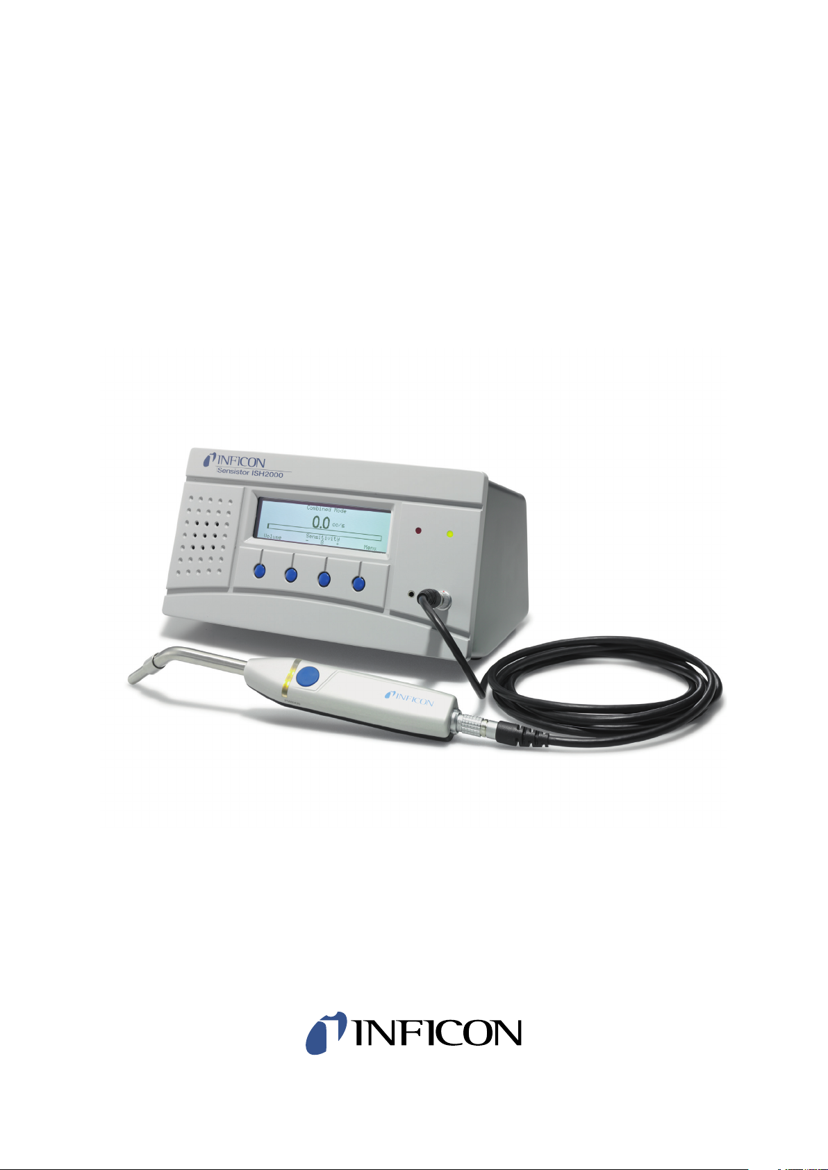
Sensistor ISH2000
HYDROGEN LEAK DETECTOR
Technical Reference Manual
Publication: INFICON AB - nipa60e1-a (1202) - All information can be modified without prior notice
Page 2

General content
A 100 Introduction to the Sensistor ISH2000 series ................................................ 5
A 300 Sensor Technologies working principle ......................................................... 6
A 400 Testing methods .......................................................................................... 7
A 401 About Hydrogen .......................................................................................... 9
A 600 Options ..................................................................................................... 10
A 700 Sensistor ISH2000 Components ................................................................. 11
A 701 Spare parts and accessories ........................................................................ 17
A 800 Sensistor ISH2000 - Technical specifications ............................................... 22
A 900 Dimensions ................................................................................................ 25
B 100 Safety instructions ...................................................................................... 29
B 110 Supplies and storage .................................................................................. 30
B 210 Connecting the detector to the installation ................................................ 31
B 300 Controlling the detector with the I/O interface ........................................... 33
B 310 Controlling the detector with a PC computer through the RS 232 interface 37
B 320 Connecting the detector directly to a printer or another device .................. 40
C 100 Getting started with the leak detector ....................................................... 45
C 200 Control panel ............................................................................................ 46
C 201 Menu system ............................................................................................. 48
C 210 Password ................................................................................................... 54
C 211 Operation of the leak detector ................................................................... 55
C 300 Calibration of the leak detector ................................................................. 57
C 304 Correlation value ....................................................................................... 62
C 305 Reference values settings ........................................................................... 63
C 410 Headphones .............................................................................................. 64
C 500 Factory configuration of the leak detector parameters ............................... 65
C 570 Date - Time - Language - Unit .................................................................... 67
C 580 Service mode och debug mode .................................................................. 68
D 100 Preventive maintenance ............................................................................. 73
D 200 General troubleshooting guide .................................................................. 74
D 300 Reference leak trouble guide ..................................................................... 76
E 100 Maintenance operations introduction ......................................................... 79
E 120 Sending the leak detection for repair to a service center ............................. 80
E 130 Functional verification ................................................................................ 81
E 140 Service menu .............................................................................................. 84
E 160 Software and documentation evolution ...................................................... 85
E 230 Sensistor ISH2000 Main board .................................................................... 86
E 410 Instrument maintenance ............................................................................. 88
E 411 Probe maintenance .................................................................................... 99
F 100 Service ...................................................................................................... 103
F 110 Disposal of product when taken out of service .......................................... 104
F 800 Tools ........................................................................................................ 105
Sensistor ISH2000 Technical Reference Manual (TRM) EN- 2
Page 3

EN- 3 Sensistor ISH2000 Technical Reference Manual (TRM)
Page 4

Introduction
A
Sensistor ISH2000 Technical Reference Manual
Detailed content
A 100 Introduction to the Sensistor ISH2000 series
A 300 Sensor Technologies working principle
A 400 Testing methods
A 600 Options
A 700 Accessories
A 800 Sensistor ISH2000 - Technical specifications
A 900 Dimensions
Sensistor ISH2000 Technical Reference Manual (TRM) EN- 4
Page 5
Sensistor ISH2000
A 100
A 100 Introduction to the Sensistor ISH2000 series
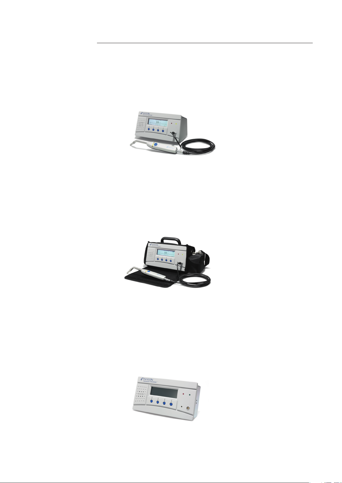
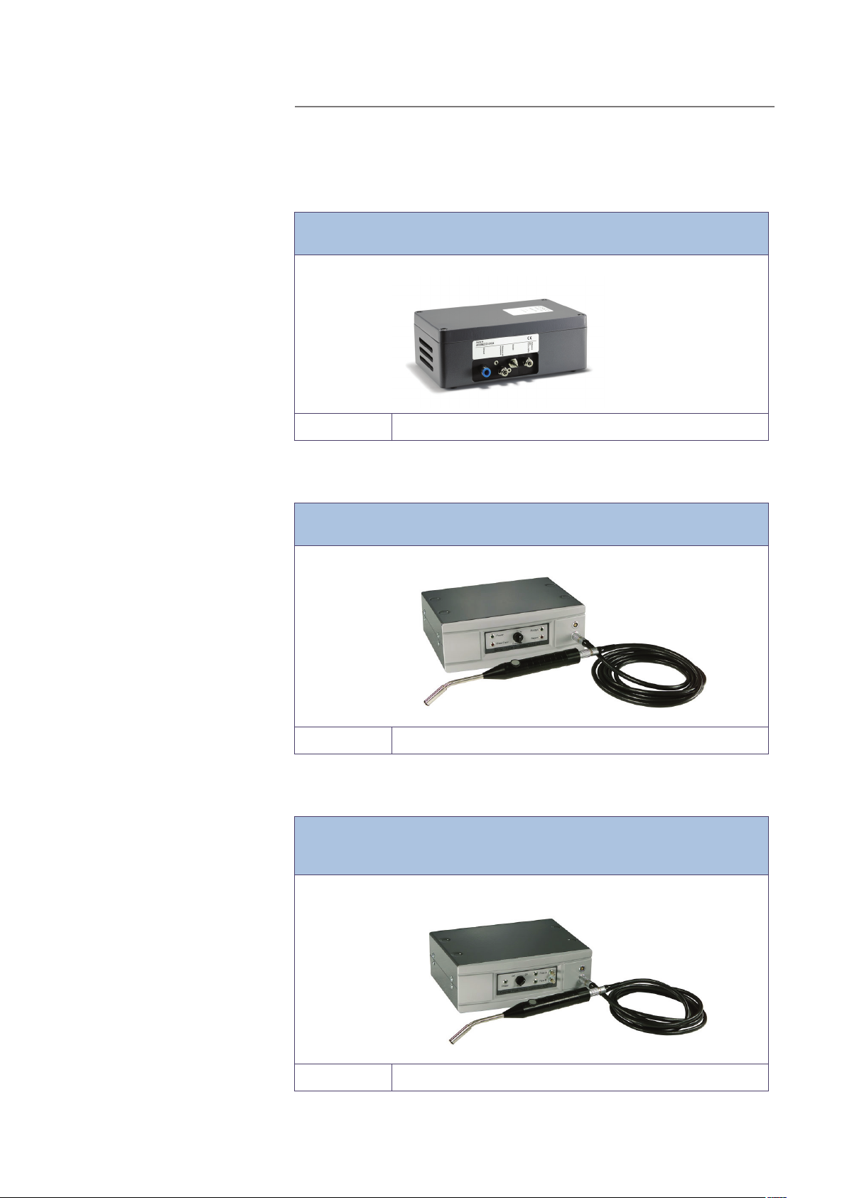
Sensistor ISH2000 can be purchased in one of three versions. A desktop model
(Sensistor ISH2000), a battery operated model (Sensistor ISH2000C), and a
panel mount model (Sensistor ISH2000P).
Figure A-1: Sensistor ISH2000
Sensistor ISH2000 is equipped with a number of powerful functions making it
very easy to integrate in a semi or fully automatic test system. The functions
range from output of all necessary status signals and printer/communication
port to an advanced Active Probe Control system (APC). This makes the detector capable of controlling advanced sample collecting devices down to simple
test fixtures.
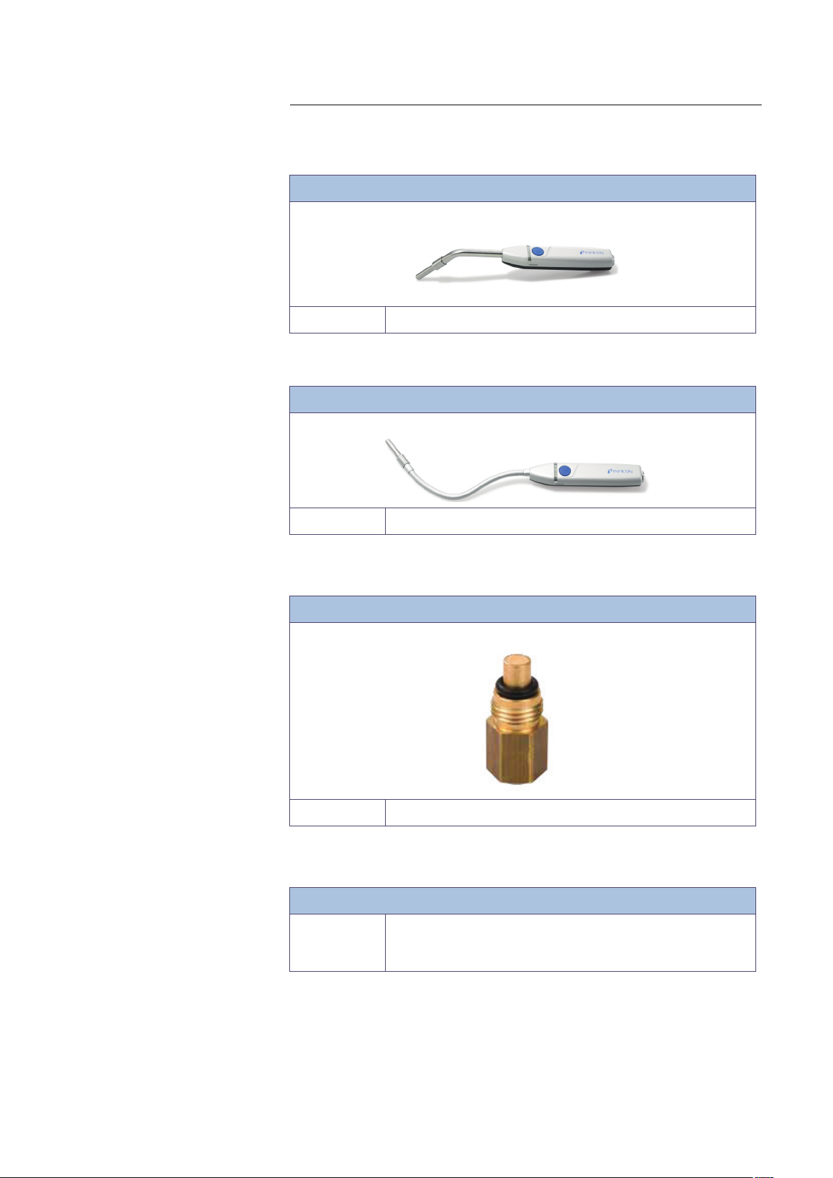
Sensistor ISH2000C
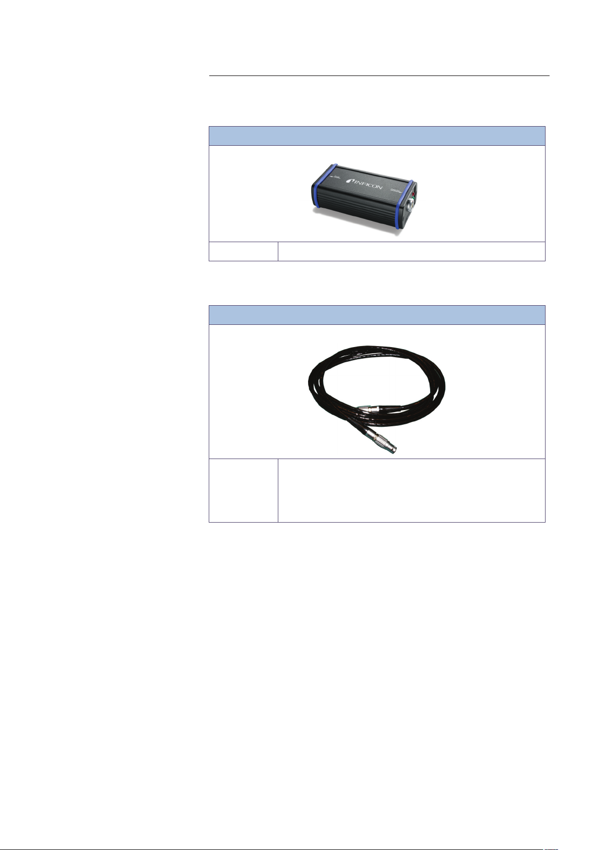
Sensistor ISH2000P
Figure A-2: Sensistor ISH2000C
The battery operated model, Sensistor ISH2000C, has all the Sensistor ISH2000
features apart from the APC system. This means that only passive probes (for
example Hand Probe P50) can be used. The battery, a Li-ion battery at 14.8 V,
can not support the current required to operate external probes. Sensistor
ISH2000C will operate for 14 hours on a fully charged battery with screensaver
and mute function. One hour charging will give about one hour of operating
time.
Figure A-3: Sensistor ISH2000P
The panel mount model, Sensistor ISH2000P, has identical features of the Sensistor ISH2000.The difference is that the Sensistor ISH2000 can be installed in
EN- 5 Sensistor ISH2000 Technical Reference Manual (TRM)
Page 6

A 300
the operator’s panel or any other flat surface. Also it operates on +24 VDC.
Mounting brackets and a panel rubber seal are delivered with the detector.
Sensistor ISH2000 Technical Reference Manual (TRM) EN- 6
Page 7

Sensor Technology
A 400
A 300 Sensor Technologies working principle
The Sensistor ISH2000 leak detector is using SENSISTOR sensor technology
inside. SENSISTOR sensor technology uses an extremely sensitive hydrogen gas
sensor based on a microelectronic field effect transistor (MOS-FET).
The gas sensitivity appears when hydrogen absorbs into the sensor through a
metal alloy (metal hydride) layer.
Only hydrogen can diffuse into the metal and this makes the sensors practically
insensitive to other substances that do not contain free hydrogen molecules.
The signals from the sensors are processed by a microprocessor which also controls the sensor temperature with high accuracy, and other sensor diagnostics in
order to ensure perfect functionality. It also automatically compensates for
background gas.
EN- 7 Sensistor ISH2000 Technical Reference Manual (TRM)
Page 8

To Detect leaks
A 400
A 400 Testing methods
If all you wish to do is to detect the presence of a leak, that is, find out whether
there is a leak or not, then use the Detection Mode (or use the detection bar in
Combined Mode). The definition of Leak/No Leak will then simply be "A leak is
a leak when it can be detected by the detector, set to a specific sensitivity".
To set up:
The operation in Detection Mode is not quantitative. The audio and visual sig-
nal will increase and decrease with the gas concentration. Therefore, there is no
actual calibration to be done, but rather a setting of the sensitivity to a desired
level.
A typical set-up procedure for Detection Mode is:
• Set up a reference leak which corresponds to the smallest leak you wish to
detect.
• Put the probe close to the reference leak and note approximately what reaction you get (no reaction, small, medium, high, full scale) within the first few
seconds.
• Set the sensitivity. This can be done permanently under the menu Detection
Mode Settings or temporarily as a Direct Sensitivity Adjustment on the display
(unless you have set this function to OFF under the Detection Mode Settings
menu).
There is also an Auto ranging function which can be selected under the Detection Mode Settings menu.
Note: If the Detection Mode is used and the alarm function is required to be
activated at a particular calibrated level, then the unit must be calibrated in
accordance with the instructions, see "Calibrate the leak detector" on page 17.
The reason for this is that the alarm is based on the Analysis Mode when the
Detection Mode is displayed.
To Locate Leaks
Note: The Detection Mode (or use the detection bar in Combined Mode) is
used to locate leaks. This mode is semi-quantitative, that is, it gives an audio
and visual signal which increases as a leak is approached (a higher gas concentration) and decreases as you move the probe away from the leak. It does not
display figures. In this mode of operation leaks can easily be detected using a
sensitivity which can be preset.
Leaks can be located very accurately, even when there are other leaks nearby. If,
for example, you are trying to locate a leak on a product and the product has a
major leak, then you will get an audio signal as soon as the probe is placed
close to the product.
When the probe is moved around and over the product, the signal will increase
as the probe approaches the leak. If the signal goes out of scale, simply reduce
the sensitivity setting to bring the signal within the scale. Working with the sensitivity setting this way you will be able to locate multiple leaks that are in close
proximity to each other.
Note: Working inside a confined space such as, for example, a cabinet or a narrow passage on a combustion engine there is a risk that the background concentration accumulates to levels close to the upper detection limit of the
detector. In such case it will not be possible to locate leaks as easily as in open
spaces.
Sensistor ISH2000 Technical Reference Manual (TRM) EN- 8
Page 9

To Quantify Leaks
A 401
Hint: It is good practice to detect a leak, locate it, and immediately remove the
probe to avoid saturation. The probe is not damaged by the exposure but it will
recover more slowly. After excessive exposure it will be less sensitive for a short
period of time.
The Analysis Mode (or use the analysis figures in Combined Mode) is used for
measuring the size of a leak (or the concentration of a gas sample). To be able
to do this measurement and obtain correct values, the instrument must first be
calibrated using the calibration function.
In the Analysis Mode the detector determines the gas concentration from the
change, as the probe goes from being exposed to background to being
exposed to a certain gas concentration. The detector does not continuously
monitor the gas concentration but takes just one reading instead. Another suitable alternative name for this mode could be Sampling Mode. It is important to
keep this in mind when using the detector in this mode.
In Analysis Mode the probe should be moved directly from a background situation to the test point. The size of the leak in PPM, or any other selected units, is
shown on the display. The probe can and should be removed from the measuring point as the measured value steadies and remains on the display. The period
during which the measured value is displayed can be adjusted in the Analysis
Mode Settings menu.
EN- 9 Sensistor ISH2000 Technical Reference Manual (TRM)
Page 10

A 600
A 401 About Hydrogen
When pure hydrogen gas is released in air its flammability range spans from 4%
to 75% of hydrogen in air. Below 4% there is insufficient chemical energy available for a flame to occur. Above 75% hydrogen there is not enough oxygen left
to support a flame. When, for example, a mixture of less than 5.5 % hydrogen
in nitrogen mixes with air there is not sufficient energy to support a flame, irrespective of the ratio of air-to-gas. When a mixture of more than 5.5 % hydrogen in nitrogen is released into air there is a region of ratios of air-to-gas where
the mixture is flammable. When, for example, a mixture of 10% hydrogen in
nitrogen mixes with air there is still very little energy available. Only in exceptional circumstances can a flame be self-supporting. However, such mixtures
cannot detonate.
Hydrogen can be stored and transported as either a gas a cryogenic liquid.
The tracer gas is standard welding gas of industry quality, easy to obtain at low
cost. The generic name is Forming Gas.
Sensistor ISH2000 Technical Reference Manual (TRM) EN- 10
Page 11

A 600 Options
Which options for which model?
A 700
Sensistor ISH2000
Sensistor ISH2000 C
Table model t
Portable model t
Panel model t
Hand probe P50 tt
3 m C21 cable tt
Sensistor ISH2000 P
Power supply cable t
Battery recharger
Cary case
Probe control port
t
t
t
t
EN- 11 Sensistor ISH2000 Technical Reference Manual (TRM)
Page 12
Sensistor ISH2000
A 700
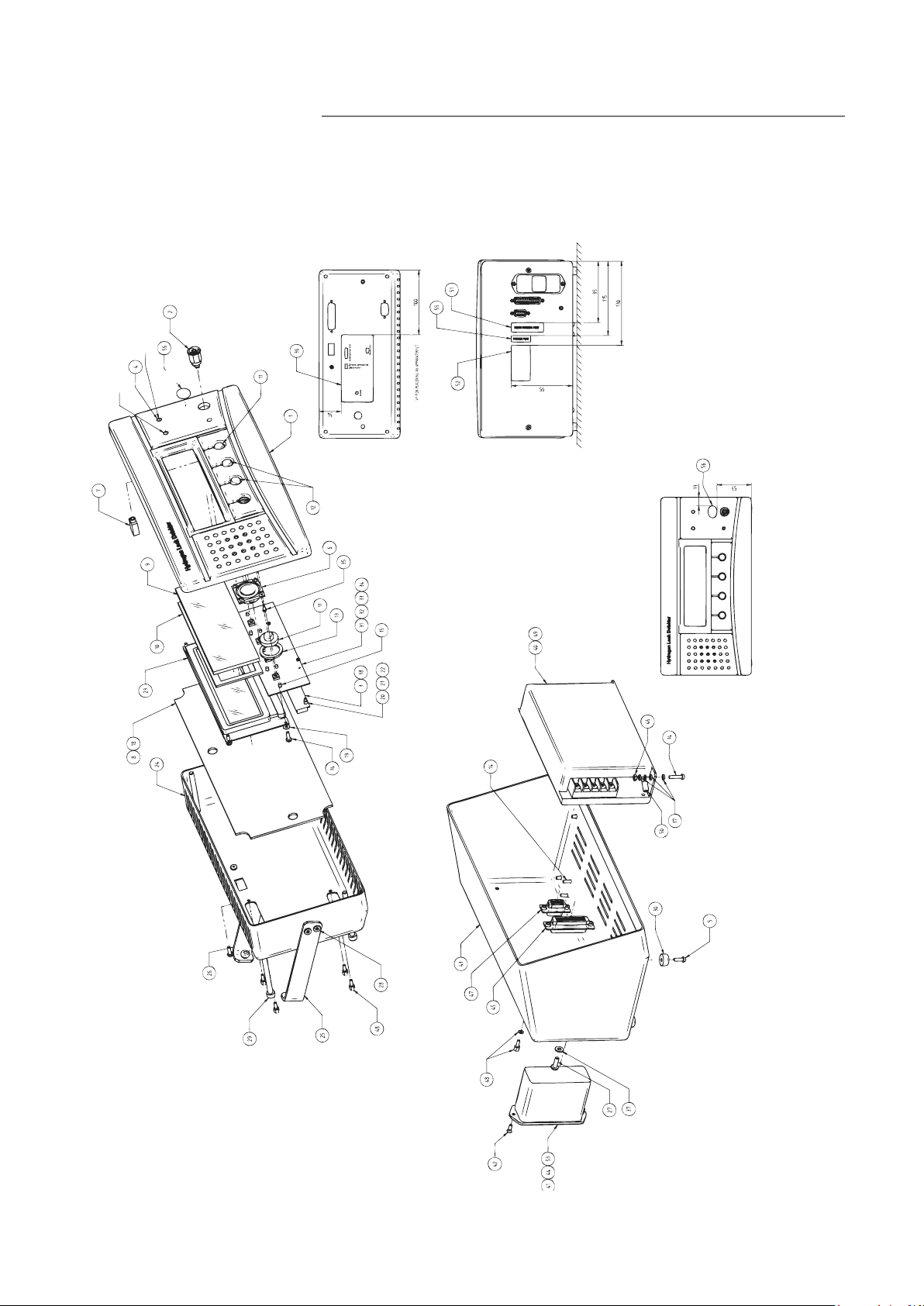
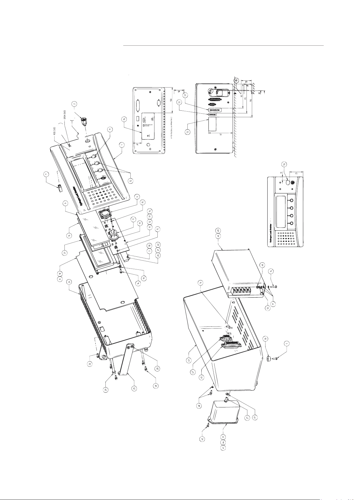
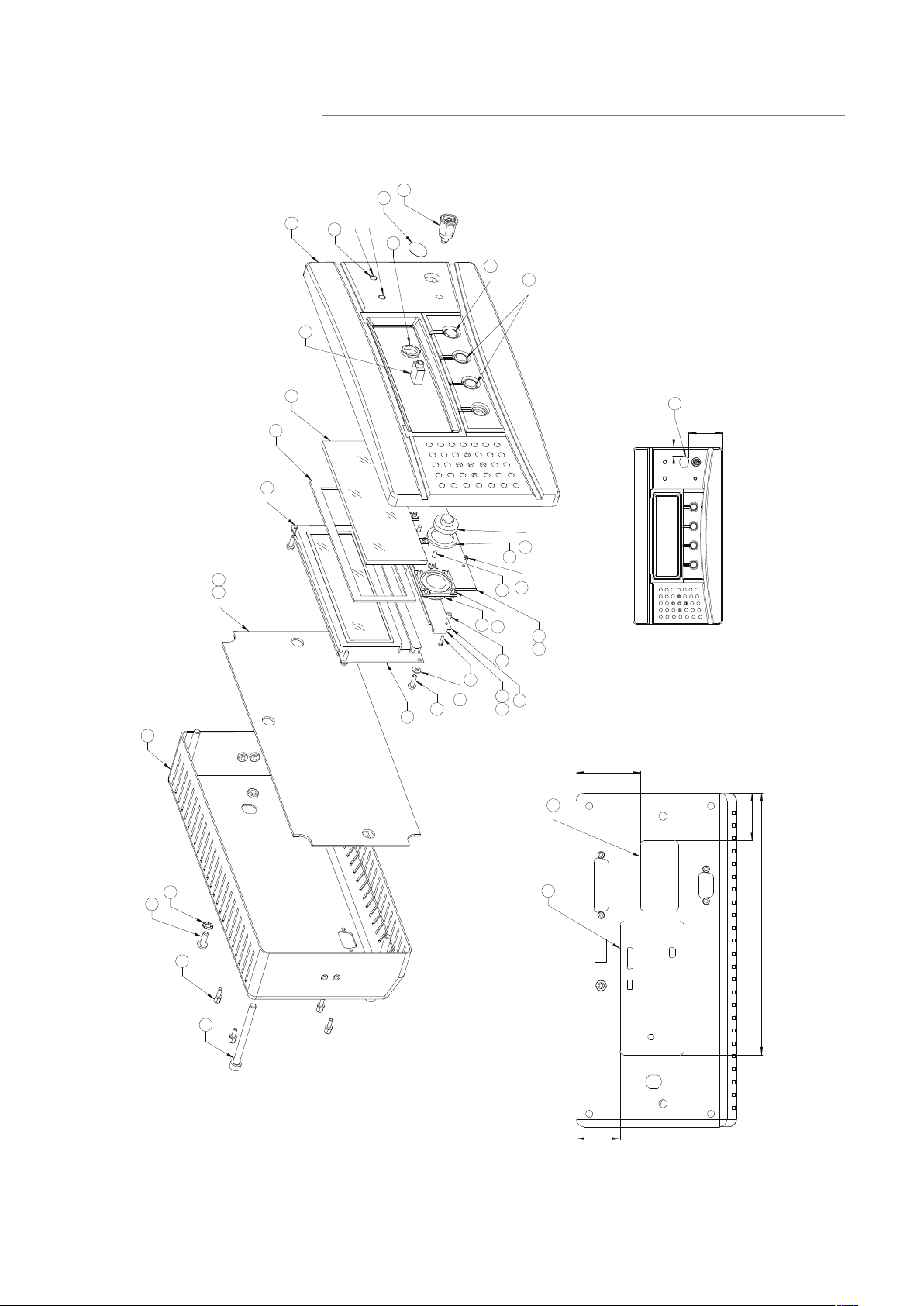
A 700 Sensistor ISH2000 Components
Green diode
Red diode
Green diode
Red diode
Figure A-4: Sensistor ISH2000 components
Sensistor ISH2000 Technical Reference Manual (TRM) EN- 12
Page 13

A 700
Sensistor ISH2000 components according to Figure A-4: on page 12.
Position P/N Position P/N Position P/N
1 598-170 21 591-493 41 591-812
2 591-770 22 591-499 42 591-607
3 591-496 23 591-494 43 598-167
4 591-771 24 598-166 44 591-578
5 591-533 25 591-502 45 591-774
6 591-773 26 591-503 46 591-013
7 591-779 27 591-487 47 591-777
8 591-780 28 591-488 48 591-538
9 598-121 29 591-490 49 591-781
10 591-501 30 591-786 50 591-772
11 591-500 31 591-497 51 598-177
12 591-515 32 591-796 52 591-809
13 598-043 33 591-797 53 591-577
14 591-791 34 591-798 54 591-317
15 591-790 35 591-787 55 598-173
17 591-775 36 598-174 56 591-810
18 591-778 37 591-266 57 591-017
19 591-532 38 591-527 58 591-142
20 591-492 40 591-482
EN- 13 Sensistor ISH2000 Technical Reference Manual (TRM)
Page 14
Sensistor ISH2000C
Green diode
Red diode
Green diode
Red diode
A 700
Figure A-5: Sensistor ISH2000C components
Sensistor ISH2000 Technical Reference Manual (TRM) EN- 14
Page 15

A 700
Sensistor ISH2000C components according to Figure A-5: on page 14.
Position P/N Position P/N Position P/N
1 598-170 19 591-532 36 598-174
2 591-770 20 591-492 37 591-266
3 591-498 21 591-493 38 591-527
4 591-771 22 591-499 39 598-178
5 591-533 23 591-494 40 591-782
6 591-773 24 598-166 41 591-328
7 591-779 25 591-502 42 591-452
8 591-780 26 591-503 43 591-806
9 598-121 27 591-298 44 591-327
10 591-501 28 591-488 45 598-172
11 591-500 29 591-490 46 591-538
12 591-515 30 591-786 48 591-785
13 598-043 31 591-497 49 591-807
14 591-791 32 591-796 50 598-173
15 591-790 33 591-797 51 591-777
17 591-775 34 591-798 52 591-810
18 591-778 35 591-787 53 591-810
EN- 15 Sensistor ISH2000 Technical Reference Manual (TRM)
Page 16
Sensistor ISH2000P
J
2
J
A 700
66,6
HQOL
(MWRO)|UULWQLQJ
Red diode
Green diode
ZP/K
'ZPE/K
$QPlUNQLQ
JlOOHU
66,62
5LWQLQJVQXPPHU
1HWWRGLPHQVLRQ0DWHULDO
,QJnUSnVPVW
6NDOD
3
/lFNV|NDUH+Y3DQHOPRGHOO
%HQlPQLQJ
3URMHNW1DPQ
091130091130091130
3(+(
*RGN
3(+(
*UDQVN
%HQlPQLQJ
(&*
.RQVWU
AC:?E6CA@CE
AC@364@?EC@=A@CE
4
5
E
?
@
=
C
#
%
G
@
4
6
@
3
C
A
4
:
5
>
?
#
%
2
G
D6?D@C
2ULJLQDOIRUPDW $
Figure A-6: Sensistor ISH2000P components
Sensistor ISH2000 Technical Reference Manual (TRM) EN- 16
Page 17

A 701
Sensistor ISH2000P components according to Figure A-6: on page 16.
Position P/N Position P/N Position P/N
1 598-170 14 591-791 29 591-490.
2 591-770 15 591-790 31 591-497
3 591-498 16 591-808 32 591-796
4 591-771 18 591-778 33 591-797
6 591-773 19 591-532 34 591-798
7 591-779 20 591-492 35 591-787
8 591-780 21 591-493 36 598-174
9 598-121 22 591-499 37 591-538
10 591-501 23 591-494 38 591-527
11 591-500 24 598-166 39 591-810
12 591-515 25 591-776
13 598-043 26 591-298
EN- 17 Sensistor ISH2000 Technical Reference Manual (TRM)
Page 18
AP29ECO Sampling Probe
AP55 Sniffer Probe
A 701
A 701 Spare parts and accessories
For automatic leak testing of entire products or parts of products. Can also be used
for testing permeability of materials.
Part No: 590-035
AP57 Counter Flow Probe
For fast manual leak location in hard to-reach places. Active probe that sniffs the
sample air past the hydrogen sensor in the probe tip.
Part No: 590-550
For leak detection in enclosed spaces or in environments with a high background
level of tracer gas. An adjustable air flow from the probe tip provides a protective air
curtain against tracer gas in the surroundings.
Part No: 590-555
Sensistor ISH2000 Technical Reference Manual (TRM) EN- 18
Page 19
P50 Hand Probes
A 701
Hand Probe P50 with rigid neck.
Part No: 590-780
With a flexible neck. Facilitates leak detection in hard-to-reach places.
Part No: 590-790
H65 Insert Sensor
Replaces the standard hand probe in automated tests.
Part No: 590-250
Probe Tip Protection Cap and filter
For Hand Probes P50 and P50-FLEX.
Part No: 591-273 (Probe Tip Protection Cap, set of 50)
590-625 (Probe Tip Protection Cap, set of 500)
591-234
EN- 19 Sensistor ISH2000 Technical Reference Manual (TRM)
Page 20
A 701
Combox
C 21 Probe Cables
This page intentionally left blank
Probe adapter for AP29ECO, H65, AP55 and AP57.
Part No: 590-820
In various lengths for comfortable leak detection in every situation.
Part No: 590-161 (3m)
590-175 (6 m)
590-165 (9 m)
590-163 (4 m, spiral)
590-164 (6 m, spiral)
Sensistor ISH2000 Technical Reference Manual (TRM) EN- 20
Page 21
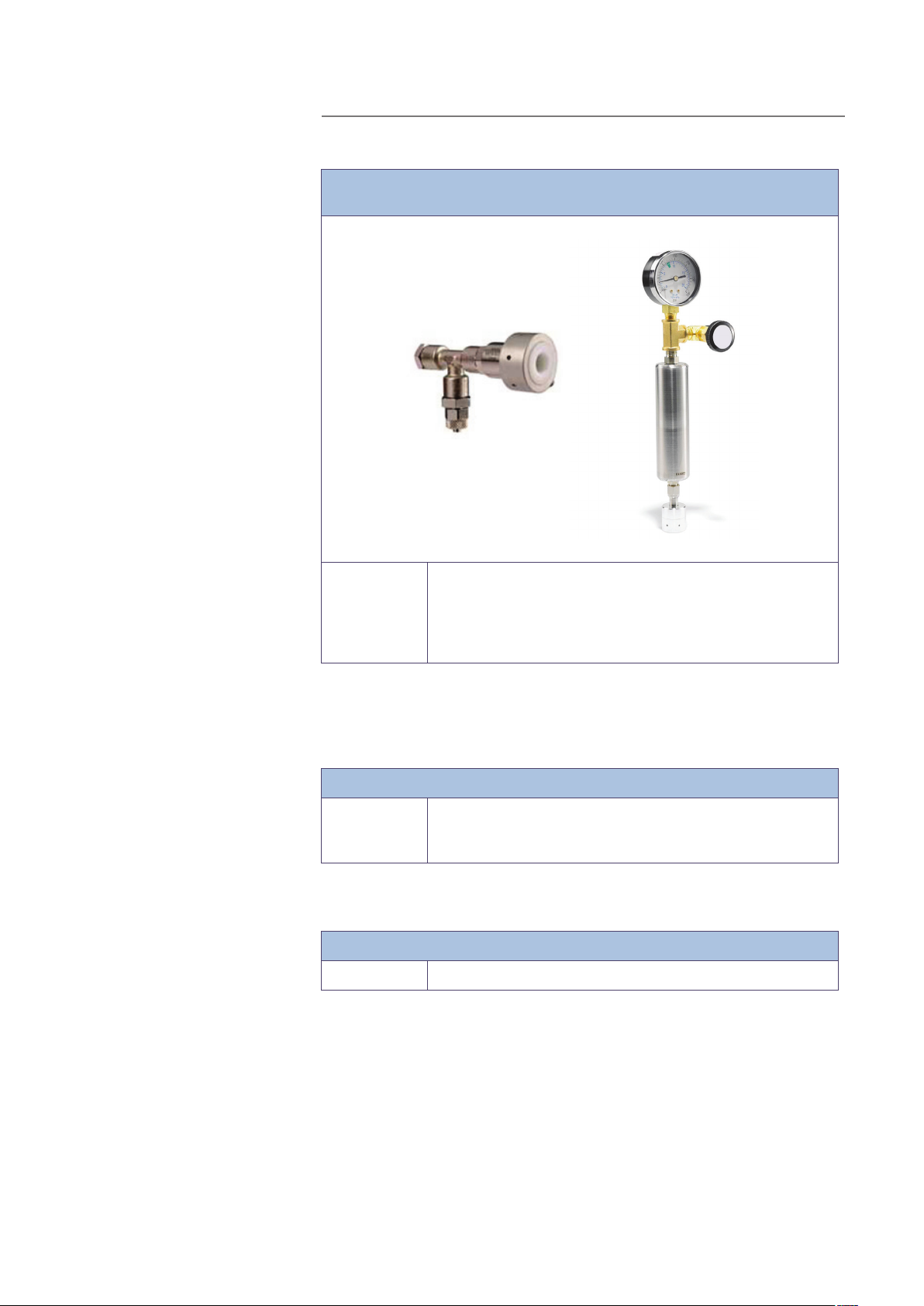
Reference Leaks
A 701
Large and small, with certificate, for calibration and function tests of the Sensistor
ISH2000.
Power cables
Fuse
Part No: 590-420 Type A 5x10
590-421 Type B 5x10
590-422 Type C 5x10
590-427 Type D 10 g/a R134a
590-429 Type G 3 g/a R134a
Power cables for Sensistor ISH2000
Part No: 591-146 (Power cable eu)
591-147 (Power cable uk)
591-853 (Power cable us)
2 A slow for Sensistor ISH2000
Part No: 591-578
-2
atm ml/s
-3
atm ml/s
-4
atm ml/s
EN- 21 Sensistor ISH2000 Technical Reference Manual (TRM)
Page 22
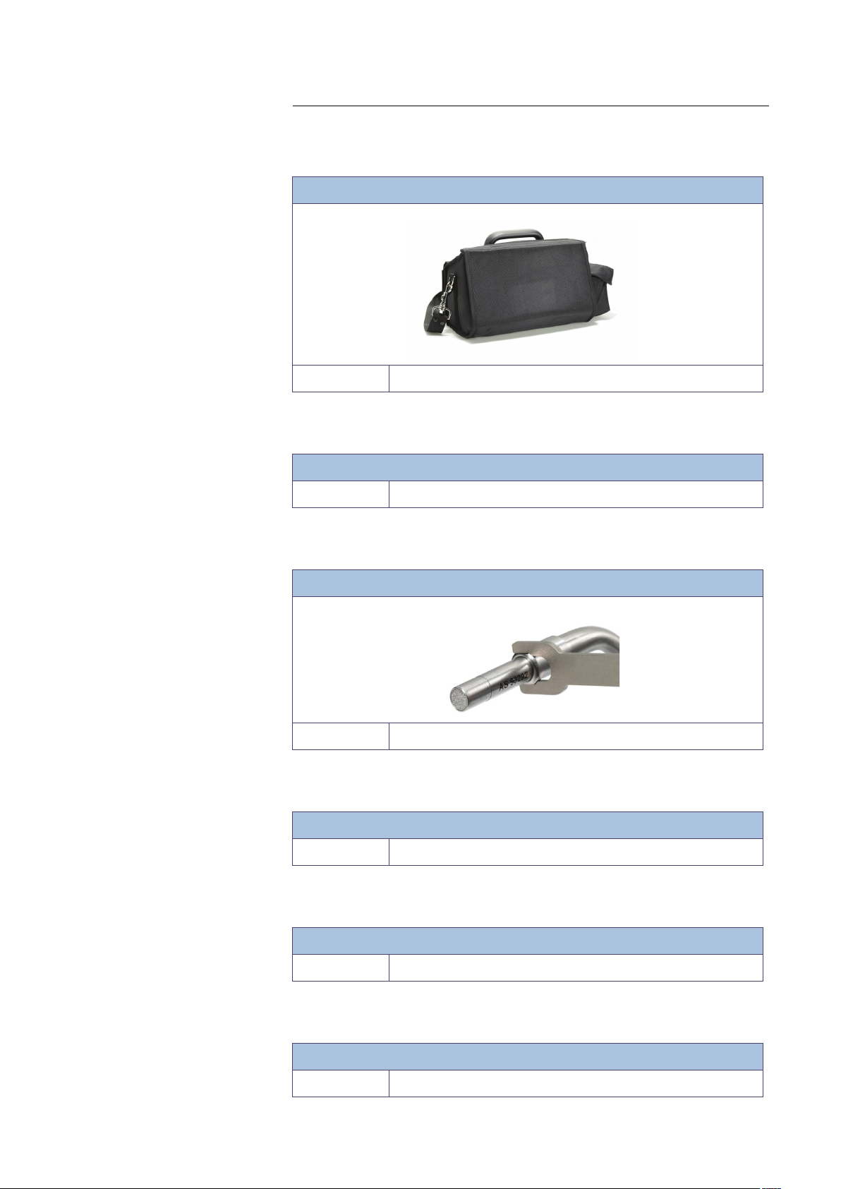
Carrying case
Battery charger
A 800
For Sensistor ISH2000C
Part No: 591-329
For Sensistor ISH2000C
Part No: 591-795
Hand Probe sensor
Sensor, for sensor replacement on P50 Hand Probe.
Part No: 590-292
Mounting kit
For Sensistor ISH2000P inkluding Brackets and seals.
Part No: 590-810
Phoenix connector to Sensistor ISH2000P
For Sensistor ISH2000P, power connection.
Part No: 591-792
O-ring seal
For Sensistor ISH2000P.
Part No: 591-528
Sensistor ISH2000 Technical Reference Manual (TRM) EN- 22
Page 23

A 800 Sensistor ISH2000 - Technical specifications
Power supply specifications
Power Sensistor ISH2000 Sensistor ISH2000C Sensistor ISH2000P
AC mains voltage 100-240 V 50/60Hz. -
A 800
AC mains voltage to the
charger
AC mains current Typically 1 A (2 A pulse at
power on).
AC mains current to the
charger
Fuse 2 A slow/ 250 VAC. - -
Nominal battery voltage - 16.1 VDC (nominal). The unit
Operating time - 8 h -
Charging time - 6.5 h -
Power supply voltage - - 24 VDC
Power supply current - - 3 A max
100-240 V50/60 Hz -
-
Typically 300 mA -
will shutdown at approx.
12VDC, and will be operational at approx. 14VDC
Input and output connections
Type Sensistor ISH2000 Sensistor ISH2000C Sensistor ISH2000P
General
Power input connector AC input connector, IES 320. Charger input connector, 2.1
x 5.5 mm std. Positive centre.
Probe control port inputs
Minimum pulse length 40 ms - 40 ms
Input impedance 50k ohm - 50k ohm
Input maximum range -34 to +38 VDC - -34 to +38 VDC
Input high > 12.0 VDC - > 12.0 VDC
Input low < 8.0 VDC - < 8.0 VDC
Probe control port outputs
Output current max 0.5 A/output, max 2.5 A
total
Inductive loads External clamp diodes
recommended
Low stage voltage Max 1.5 VDC - Max 1.5 VDC
- max 0.5 A/output, max 2.5 A
- External clamp diodes rec-
4 pin Phoenix MC 1.5/5.81
Series Detachable screw terminal.
total
ommended
EN- 23 Sensistor ISH2000 Technical Reference Manual (TRM)
Page 24

A 800
Type Sensistor ISH2000 Sensistor ISH2000C Sensistor ISH2000P
Short circuit protection Thermal and electronic - Thermal and electronic
Output high 22-24 VDC - > (Supply voltage – 2.5 VDC)
Output low < 1.5 VDC - < 1.5 VDC
Serial communication port
Connector 9-pol D-sub male 9-pol D-sub male 9-pol D-sub male
Standard RS232 RS232 RS232
Probe control/Status port
Connector 25-pin D-sub female 9-pin D-sub female -
Miscellaneous specifications
Misc Sensistor ISH2000 Sensistor ISH2000C Sensistor ISH2000P
Protection (IEC529) IP64 (front), IP32 (back) IP63 (in carrying case) IP64 (front), IP32
(back)
Net weight 3.9 kg (8.6 lb) 4.0 kg (8.8 lb)
4.9 kg (10.8) incl. case,
probe and charger
Overall dimensions 275 x 155 x 170 mm
(11 x 6 x 7 inches)
Environment
temperature
Environment
humidity
0-50°C 0-50°C 0-50°C
10-90% RH 10-90% RH 10-90% RH
275 x 190 x 170 mm
(11 x 7 x 7 inches)
1.8 kg (4.0 lb)
275 x 140 x 75 mm
(11 x 6 x 3 inches)
Gas sensing specification (In Detection Mode)
Selected unit Sensitivity
mbarl/s air (using 5% H2/
95% N
Tracer Gas)
as
2
1 x 10
-7
mbarl/s
g/a R143a (using 5% H
as
95% N
2
Tracer Gas)
Sensistor ISH2000 Technical Reference Manual (TRM) EN- 24
/
0.02 g/a
2
Page 25

Gas sensing specification (In Analysis Mode)
A 900
Selected unit Sensitivity Measurement
range
ppm (H
mbarl/s air
(using 5% H
95% N
Tracer Gas)
g/a R143a (using
5% H
as Tracer Gas)
) 0.5 ppm 0.5 - 2000 ppm
2
as
2
/95% N
2
-7
/
2
2
5 x 10
0.2 g/a 0.2 - 8300 g/a Typ. ± 15% of reading
mbarl/s 5 x 10⁻⁷ - 4 x 10⁻²
(0.2%)
mbarl/s
Linearity Repeatability
Typ. ± 15% of reading
(within 0.1 - 10 x
calibration point in
range 0.5 - 100 ppm)
Typ. ± 15% of reading
(within 0.1 - 10 x
calibration point in
range 1 x 10
-
10
3
mbarl/s)
(within 0.1 - 10 x
calibration point in
range 0.2 - 420 g/a
-5
- 2 x
Typ. ± (10% of
reading + 0.3 ppm)
Typ. ± (10% of
reading + 3 x 10
mbarl/s)
Typ. ± (10% of
reading + 0.1 g/a)
-7
EN- 25 Sensistor ISH2000 Technical Reference Manual (TRM)
Page 26
Sensistor ISH2000
A 900
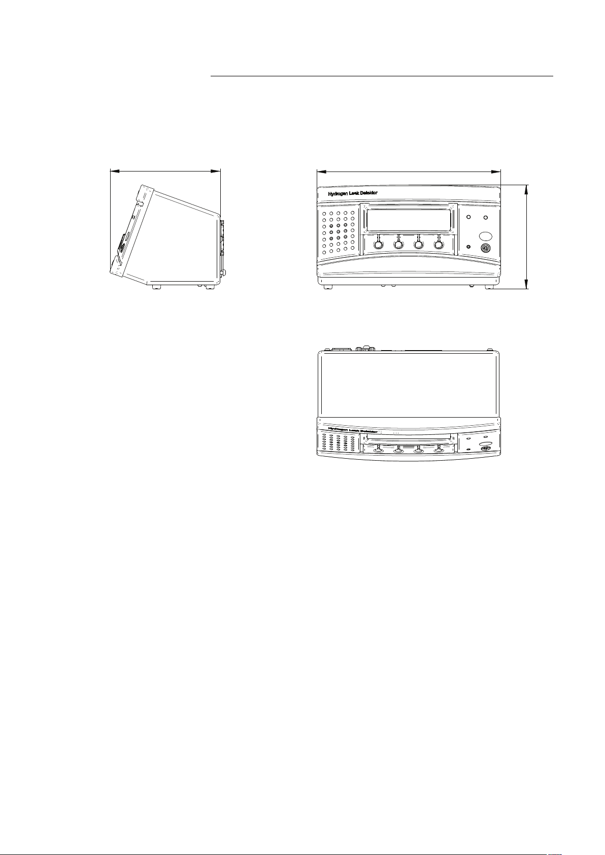
A 900 Dimensions
165 / 0.54
275 / 0.9
156 / 0.51
Figure A-7: Sensistor ISH2000 dimensions
Sensistor ISH2000 Technical Reference Manual (TRM) EN- 26
Page 27
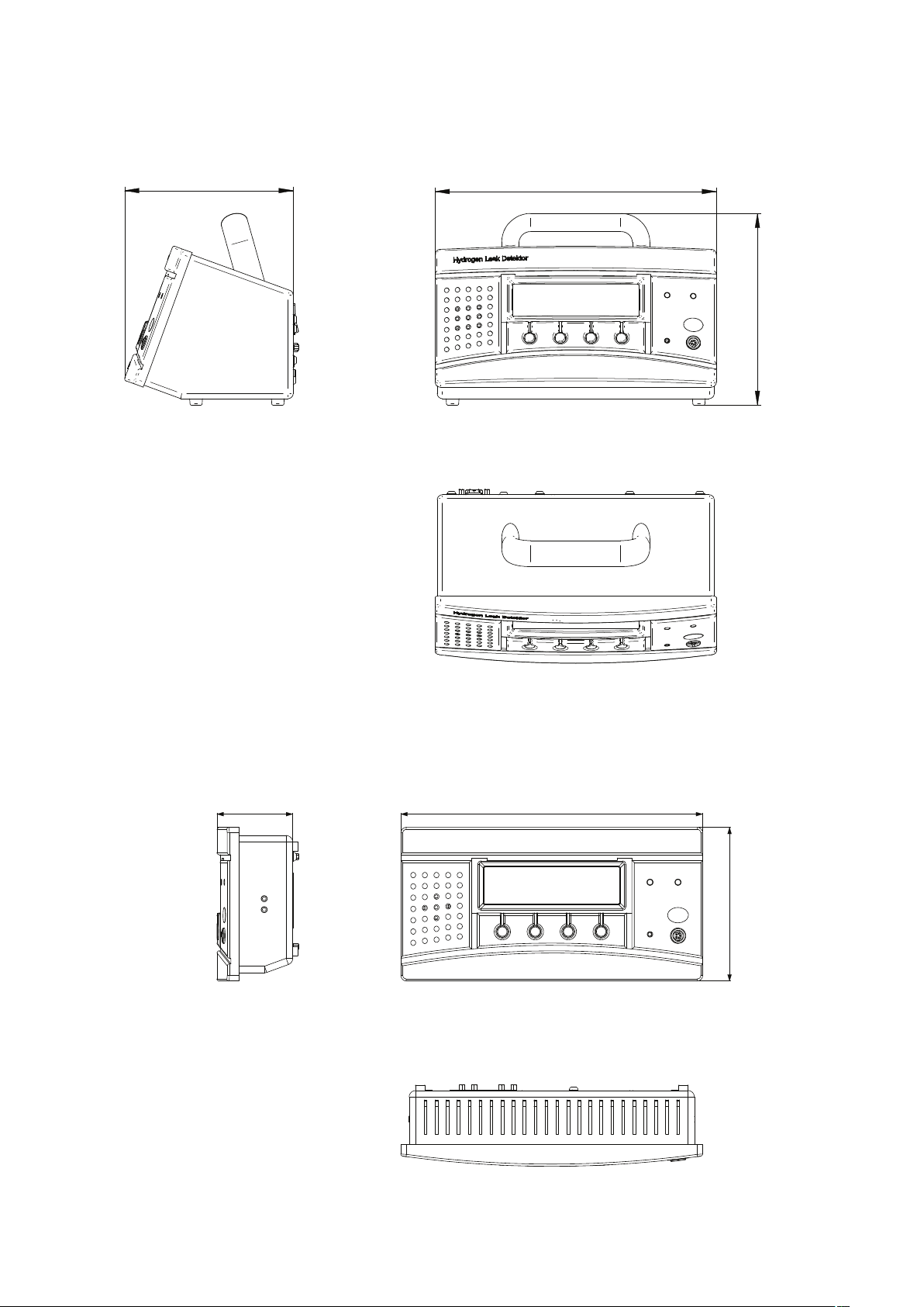
Sensistor ISH2000C
This page intentionally left blank
165 / 0.54
275 / 0.9
188 /0.62
Sensistor ISH2000P
Figure A-8: Sensistor ISH2000C dimensions
Figure A-9: Sensistor ISH2000P dimensions
EN- 27 Sensistor ISH2000 Technical Reference Manual (TRM)
Page 28

Installation
B
Sensistor ISH2000 Technical Reference Manual
Detailed content
B 100 Safety
B 110 Storage - transportation
B 210 Connecting the detector to the installation
B 300 Controlling the detector with the I/O interface
B 310 Controlling the detector with a PC computer through RS 232
B 310 Connecting the detector directly to a printer or another device
Sensistor ISH2000 Technical Reference Manual (TRM) EN- 28
Page 29
B 100
B 100 Safety instructions
The normal risks associated with working with all compressed gases must be
considered.
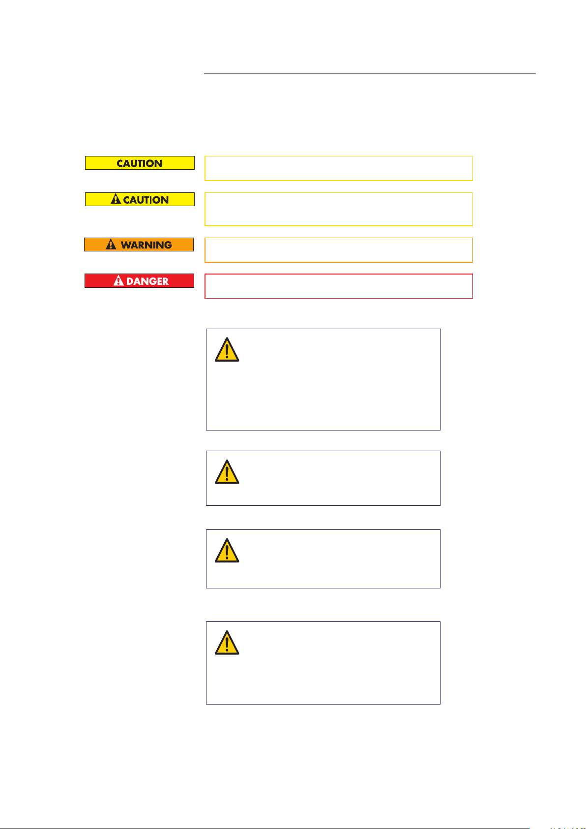
Indicates a potentially hazardous situation which, if not avoided, could result in
property damage.
Indicates a potentially hazardous situation which, if not avoided, could result in
moderate or minor injury. It may also be used to alert against unsafe practices.
Indicates a potentially hazardous situation which, if not avoided, could result in death
or severe injury.
Indicates an imminently hazardous situation that, if not avoided, will result in death or
severe injury (extreme situations).
WARNING!
Pure hydrogen is a flammable gas. Only use readymade Hydrogen Tracer Gas of 5% Hydrogen in
Nitrogen. This is a standard industrial gas mixture
used in various industrial applications.
Note:
Whenever the word Hydrogen is used in
this manual it implies that the hydrogen gas is
safely mixed with Nitrogen in the proportions
- 95% N2.
5% H
2
Leak detector label
WARNING!
Since the tracer gas mix contains no oxygen,
releasing large amounts of gas in a confined space
may lead to asphyxiation.
WARNING!
Compressed gases contain a great deal of stored
energy. Always carefully secure gas bottles before
connecting pressure regulator. Never transport gas
bottle with the pressure regulator fitted.
Before connecting tracer gas: confirm that the connectors or test object is designed
for working at the test pressure.
WARNING!
Pressurising objects at too high pressures can result
in a burst object. This in turn can result in serious
injury or even death.
Never pressurise objects that have not previously
been burst tested or otherwise approved for the
chosen test pressure.
Located at the back of the Sensistor ISH2000, a label indicates the electrical
specifications of the leak detector and its serial number.
EN- 29 Sensistor ISH2000 Technical Reference Manual (TRM)
Page 30

Supplies
B 110
B 110 Supplies and storage
The following parts are supplied with your detector:
Sensistor ISH2000 Sensistor ISH2000C Sensistor ISH2000P
Detector unit Detector unit Detector unit
Storage
Hand Probe P50.
Optional P50-Flex
Probe cable C21 Probe cable C21 Screws
Power cable (the power
cable is country specific
and may differ)
User manual User manual User manual
User manual CD User manual CD User manual CD
Product return form Product return form Product return form
Sample Kit Probe Tip Prot Sample Kit Probe Tip Prot Phoenix contact
For prolonged storage, factors such as temperature, humidity, saline atmosphere, etc. may damage the detector elements.
Please call your local representative for further information.
Hand Probe P50. Optional
P50-Flex
Battery charger (the battery charger are country
specific and may differ).
Case
Brackets
O-rings seal
Sensistor ISH2000 Technical Reference Manual (TRM) EN- 30
Page 31

B 210 Connecting the detector to the installation
Ports and connections Sensistor ISH2000
Mounting plate screw hole
Probe control port
B 210
Power input
Printer port
Figure B-1: Sensistor ISH2000 back panel
Sensistor ISH2000 connections
Active Probe Control (APC) port.
See B 300.
Power switch
Fuse
Power input, 100-240 VAC
Printer connection, RS232 commands and APC driver installation.
Figure B-2: Sensistor ISH2000 connections
EN- 31 Sensistor ISH2000 Technical Reference Manual (TRM)
Page 32

Sensistor ISH2000C connections
Battery charger
Figure B-3: Sensistor ISH200 C connections
B 210
Printer connection, RS232 commands and APC driver installation.
Sensistor ISH2000P connections
Power input, 24V
Probe
Active Probe Control (APC) port.
See B 300.
Printer connection, RS232 commands and APC driver installation.
Figure B-4: Sensistor ISH2000P connections
Sensistor ISH2000 Technical Reference Manual (TRM) EN- 32
Page 33

I/O Interface
B 300
B 300 Controlling the detector with the I/O interface
The Sensistor ISH2000 is equipped with a parallel Probe Control port. This
Probe control port can be used for controlling active probes, feeding status signals to a supervising computer system, and for simple test fixture control.
Note: Battery operated model Sensistor ISH2000C does not have a Probe Control Port.
Pin configuration for the different detector models is described under Model
Specific Specifications below.
See "Sensistor ISH2000 Technical Specifications" on page page 23 for electrical specifications.
EN- 33 Sensistor ISH2000 Technical Reference Manual (TRM)
Page 34

Probe Control Port Connector
The control port connector is a 25-pin female D-sub.
B 300
Pin Type Signal name
1 - GND
2 - GND
3 - GND
4 In In_0
5 In In_1
6 In In_2
7 In In_3
8 In In_4
9 Out CAL_CONF
10 Out OUT_6
11 - GND
12 - GND
13 - GND
14 OUT DET_ERROR
15 OUT LEAK_OUT
16 OUT DET_ON
17 OUT DET_SIGNAL
18 OUT DET_WAIT
19 OUT OUT_0
20 OUT OUT_1
21 OUT OUT_2
22 OUT OUT_3
23 OUT OUT_4
24 OUT OUT_5
25 OUT 24 VDC OUT
Sensistor ISH2000 Technical Reference Manual (TRM) EN- 34
Page 35

Status signal patterns
B 300
Status signals for pin 14 - 18.
Figure B-5: Example screen
Where:
I/0 name on the screen Signal Name on the pins Function
Inputs 0 to 4 In_0 to In_4 Input signal
Outputs 0 to 6 Out_0 to Out_6 Output signal
Status O DET_ON When detector is on
Status W DET_WAIT High during warm-up
Status S DET_SIGNAL Gas detected / Sensor not
recovered
Status R LEAK_ALARM Leak above Reject Level
detected
Status C CAL_CONF Calibration preformed
and ok
Status E DET_ERROR High if Probe, Sensor or
Cable is broken
DET_ERROR will go high for a short time (1-5 seconds) when the detector is
switched on. It will go low when the sensor has been checked. In normal operation, DET_ERROR = HIGH means that there is a problem with the sensor,
probe, or cable.
DET_WAIT is high when instrument is in warm-up mode after switching on
power. Instrument will also go into warm-up if there is a temporary fault in the
sensor or sensor connection.
The timing of the status signals in relation to different events is described by the
following two examples:
• Example: Input signals issued to control the APC system should have a pulse
length of at least 40 ms.
• Example: Output signals switch with a cycle time of 20 ms (0.02 s). This is the
cycle time of the APC system.
Note: Not valid for battery operated version of Sensistor ISH2000.
EN- 35 Sensistor ISH2000 Technical Reference Manual (TRM)
Page 36

DET_ERROR
DET_ON
DET_WAIT
DET_SIGNAL
LEAK_OUT
B 300
Status signal after power on
Power onPower off Warming up Detection or analysis
mode. No gas detected.
Figure B-6: Status signals after power on
Status signal when detecting a gas signal
Gas signal
Purge level
Reject level
Detector signal level
0 PPM
DET_SIGNAL
LEAK_OUT
PURGE_LEVEL Trigger
(APC)
Figure B-7: Status signals when detecting a gas signal
Sensistor ISH2000 Technical Reference Manual (TRM) EN- 36
Page 37

B 310 Controlling the detector with a PC
computer through the RS 232 interface
RS 232 interface
The RS 232 interface makes it possible to control the leak detector with a PC
compatible computer: it is installed on all leak detectors.
Commands available for your leak detector
RS232 interface commands
Setting No printer PC printer Data output
Data rate 115200 baud 1200 baud 9600 baud
Data bits 8 8 8
B 310
Stop bits
Parity
Flow control
Common used functions
Command Header
Calibrate K
Measure M
Print Request N
Stop Measurement Q
Hand Probe R
Active Probe (Installed AP) S
Analysis Mode X
Detection Mode Z
Combined Mode Y
111
None None None
None None None
K = Calibration request
Starts calibration if the Sensistor ISH2000 has an active probe driver installed.
Sensistor ISH2000 answers with a "K" if an active driver containing a calibration routine was found and "F" if the calibration APC sequence not found. Calibration doesn’t start if Purge level is reached.
M = Measure Request
The active test cycle defined by the APC driver starts. “M” is returned if the
selected driver supports active test. “F” (failed) is returned otherwise.
N = Print Request
Returns current analysis value.
EN- 37 Sensistor ISH2000 Technical Reference Manual (TRM)
Page 38

B 310
Q = Set APC in stand by, (stop a measurement)
Returns a “Q”.
R = Activates probe 0 (built in P50 driver)
Returns an “R”.
S = Activates probe 1 (Installed probe driver)
Returns an “S”.
X = Shift State to "Analysis Mode"
Returns nothing.
Z = Shift State to "Detection Mode"
Returns nothing.
Y = Shift State to “Combined Mode”
Return nothing.
Supported parameters
The following parameters can be downloaded to Sensistor ISH2000 in Analysis
and Detection mode.
Where: “Header” + “?” returns the a value from the instrument. This value is
presented as “A”, “B” and so on.
Parameter Header Data
Reject Level A n.nnE+nn
Correlation Value B n.nnE+nn
Analysis Unit C Text string (max 12 char-
acters)
Analysis Unit (Default list
unit**)
Timer A D nnn*
Timer B E nnn*
Timer C F nnn*
Timer D G nnn*
Purge Level H n.nnE+nn
Reference Value I n.nnE+nn
Reference Unit J Text string (max 12 char-
Reference Unit (Program
settings)
CUx x=1 to 10, 1=PPM, 2=CC/
S up to 10
acters)
JUx x=1 to 10, 1=PPM, 2=CC/
S up to 10
* entered as integer in 10’s of seconds, 1= 0.1s, 100 = 10s, 60000= 6000s
Default listed unit
PPM, cc/s, cc/min, SCCM, g/a, oz/yr, mbarl/s, mm3/s, mm3/min, Pa m3/s
Transfer of parameters
Send parameters one by one; send the specific header and then send the data
(for example “1.00E+01”). String must be ended with a carriage return character, chr13 (dec).
Example: “CPPM” or “C PPM”, Carriage Return (chr 13). This sets Reject Level
Rate Unit to “PPM”.
Sensistor ISH2000 Technical Reference Manual (TRM) EN- 38
Page 39

APC driver installation
B 310
Parameters can be sent in any order you like:
• If your data was received and correct, Sensistor ISH2000 immediately echoes
(sends back) the data.
• If you send a non existing header you will not receive anything.
• If the data could not be converted in the Sensistor ISH2000 you will receive
the string “CoEr”, (Conversion Error).
Note: Remember to use capitals for the header.
APC drivers are installed in the detector from a PC. All active probes need a
driver to be installed before they can be used.
Note: Battery operated model Sensistor ISH2000 does not incorporate the APC
feature.
For driver installation you will need the following:
• APC Driver software. (Delivered with the probe.)
• File transfer cable. (Delivered with the probe.)
• PC computer with Windows XP with .NET Framework 2.0 or later.
Refer to chapter “F 800” on page 105.
EN- 39 Sensistor ISH2000 Technical Reference Manual (TRM)
Page 40

B 320 Connecting the detector directly to a printer or another device
For detailed information please refer to document RS 232 for leak detectors
users manual.
Printer port
The Sensistor ISH2000 is equipped with a serial printer port. This is the 9-pin Dtype connector. It is used for printer connection, RS232 commands and APC
driver installation.
Note: Always switch power off before disconnecting or connecting any cable.
Preparing the RS 232 link cable
Use INFICON cable, P/N: 103616, or make your own by following the pin connections specified below:
Use a Sub D9 pin, female connector (7 and 8 connections are necessary only if
RTS and CTS are used in an user software).
Connector pin configuration
B 320
Pin Signal Comment
1 Not used
2 RX Received data
3 TX Transmitted data
4 (DTR) Not used
5 SG Signal ground
6 (DSR) Not used
7 (RTS) Not used
8 (CTS) Not used
9 (RI) Not used
Only pin 2 (Received data), pin 3 (Transmitted data) and pin 5 (Signal ground)
are used.
CD
RxD
TxD
DTR
SG
DSR
D9 Female
RTS
CTS
RI
1
2
3
4
5
6
7
8
9
1
2
3
4
5
6
7
8
9
CD
RxD
TxD
DTR
SG
DSR
RTS
CTS
RI
D9 Female
Figure B-8: D9 Null modem cable wiring diagram
Sensistor ISH2000 Technical Reference Manual (TRM) EN- 40
Page 41

Connecting the detector to a computer
For example, the user can communicate easily with the detector using the Terminal or Hyper Terminal program in Windows®.
Selectable printer types
Most PC-printers with serial interface can be connected to the 9-pin printer
port. Parallel (Centronics) interface printer can be used if connected through a
serial to parallel converter. The port can be set up for the following printer
types: PC Printer and Data Dump.
No printer
Printer output disabled. Incoming communication is enabled. Sensistor ISH2000
listens for incoming data but will not print/send test results.
PC printer (with serial interface)
The PC Printer option can be used to print data on most standard PC printer
with serial interface. Parallel interface printers can be used if connected through
a serial to parallel converter.
Note: The output format has been chosen to be as simple as possible to ensure
that most printers will accept it. Therefore, the printer output does not use any
flow control. This means that some printers may delay printing until the input
buffer is full or a pre-defined timeout has elapsed.
Figure B-9:
B 320
Setting Value
Data rate 1200 baud
Data bits 8
Stop bits 1
Parity None
Flow control None
Note: Due to the large variety of printers available on the market, INFICON
AB does not take responsibility for the operation of a particular type of printer.
Printed data
The detector can print the following information:
1 Date and Time for Power on of detector.
2 Time of print.
3 Value of all gas signals above the Reject Level.
4 Test result: “Accept” or “Reject”.
5 Value of signal obtained during active test.
6 Result of calibration: “OK” or “Calibration Not saved”, Date and Time,
Parameter settings.
Printing of the current value can also be requested by an RS232 command or
ordered manually by pressing PRINT.
EN- 41 Sensistor ISH2000 Technical Reference Manual (TRM)
Page 42

Probe type determines information printed.
Probe type Data printed
Hand Probe P50 1, 2, 3, 4, 6
B 320
Counter Flow Hand Probe
AP57
Sniffer Hand Probe AP55 1, 2, 4, 5, 6
Sampling Units AP29 and
H28
APC driver with active test
(using MEAS flag)
APC driver not using
MEAS flag
1, 2, 3, 4, 6
1, 2, 4, 5, 6
1, 2, 4, 5, 6
1, 2, 3, 4, 6
Analysis data output
The Analysis Data Output option is intended for transferring test results to a
supervising computer system such as, for example, a PLC system.
Communication specifications.
Setting Value
Data rate 9600 baud
Data bits 8
Stop bits 1
Parity None
Flow control None
The data format for Analysis data output consists of nine ASCII characters.
Seven characters show the value in engineering format one character shows
the result of the test, and one character shows line feed (LF).
The character indicating the result of the test is one of the following.
Character Result of the test
A Accept. Previous test was below Reject Level alarm limit.
R Reject. Previous test was above Reject Level alarm limit.
P Rejected by Purging. Previous test was above purge limit
(and Reject level limit).
C Calibration approved. Previous cycle was calibration.
Calibration was approved.
F Calibration failed. Previous cycle was calibration.
E Test interrupted by “Error” that occurred during cycle
(probe or sensor error etc.).
Sensistor ISH2000 Technical Reference Manual (TRM) EN- 42
Page 43

B 320
Example: 2.5E-04R (LF)
This example is a line feed (LF), R means that the test was above the Reject Level
alarm limit, and the value was 2.5E-04.
For passive probes (for example P50 and AP57*) data is printed when a signal is
detected above Reject Level or when the print button is pressed. Activate this
under Measure Button menu.
For active probes (e.g AP29) data is printed at end of measurement sequence.
Printing of the current value can also be requested by an RS232 command or
ordered manually by pressing PRINT.
* A custom APC program setting the MEAS flag prints as AP55/AP29 and an
APC program not using MEAS flag prints as P50.
Detection data output
The Detection Data Output option is intended for automated scanning of weld
seams etc.
Note: The Detection Data is expressed in arbitrary units. Detection Mode signal
is not affected by calibration!
Communication specifications.
Setting Value
Data rate 9600 baud
Data bits 8
Stop bits 1
Parity None
Flow control None
The data format for Detection data output contains of ten ASCII characters.
Nine characters show the value in engineering format, and one character shows
linefeed (LF).
The print time is 50Hz continuous streaming data.
EN- 43 Sensistor ISH2000 Technical Reference Manual (TRM)
Page 44

Operation
C
Sensistor ISH2000 Technical Reference Manual
Detailed content
C 100 Getting started with the leak detector
C 110 Operating principle of the control panel
C 200 Control panel
C 201 Menu system
C 210 Password
C 211 Operation of the leak detector
C 300 Calibration of the leak detector
C 304 Correlation Value
C 305 Calibrated leak values programming
C 410 Headphone and loudspeaker
C 500 Factory configuration of the leak detector parameters
C 570 Date - Time - Language - Unit
C 580 Service mode och debug mode
Sensistor ISH2000 Technical Reference Manual (TRM) EN- 44
Page 45

Starting up / switching off the leak detector
To familiarize oneself with the control panel
C 100
C 100 Getting started with the leak detector
1. Connect power.
2. Connect the probe.
3. Start the unit and wait approximately 1 minute.
4. Select probe in the menu.
Refer to C 211 “C 211 Operation of the leak detector” on page 55.
Refer to “C 200 Control panel” on page 46 for the control panel description.
EN- 45 Sensistor ISH2000 Technical Reference Manual (TRM)
Page 46

Description
C 200
C 200 Control panel
Control push-buttons
Graphic interface
Earphone socket
Probe connector
LEDs
Figure C-1: Sensistor ISH2000 control panel
The display shows:
• indicator bar in Detection Mode and the figures in Analysis Mode.
• seven main menus. Their positions are indicated on a horizontal scale. Change
from one menu to another using the < and > buttons.
• main menus have submenus, which are also indicated by horizontal scales
and can be selected using the < and > buttons.
• scales for setting numeric values, languages, etc.
• messages.
Sensistor ISH2000C:
• A battery status indicator in the upper right corner, where 13.5 V indicates
discharged state and 16.0 V indicates that the battery is fully charged.
• six main menus. Their positions are indicated on a horizontal scale. Change
from one menu to another using the < and > buttons.
LEDs
The two LEDs indicate the status of the instrument as follows:
• Green flashing slowly, during warming up phase.
• Green fixed light indicates that instrument is ready and hydrogen signal is
below Reject Level limit.
• Red fixed light together with Reject on display means the instrument has
detected a leak larger than the set alarm limit. Red flashing rapidly, check message on screen. (See “Trouble-shooting” on page 74.
Sensistor ISH2000 Technical Reference Manual (TRM) EN- 46
Page 47

Push-buttons
Demo Mode
C 200
The functions of the push-buttons are shown at the lower edge of the display.
In this manual the buttons are numbered, from left to right, 1, 2, 3, and 4. The
push-buttons are used to:
• Change from one menu item to another using the < and > buttons.
• Press Enter to move down to the nearest submenu.
• Press Save to save the set value.
• Press Undo to restore the previously set value.
Press Esc to move up to the nearest higher level(s).
Demo Mode is a demonstration mode, special designed for seller. All APC drivers for standard probes and filler will be selectable. The seller can easily swap
between the different drivers and won't need to download them.
To set the Detector in Demo Mode:
• Select: Menu/General Settings/Change Password
• Enter "DEMO"
• Confirm New Password "DEMO"
Select driver under menu: APC Settings/Probe Type
The word "DEMO" will be shown at start up.
To turn Demo Mode off repeat the list above.
EN- 47 Sensistor ISH2000 Technical Reference Manual (TRM)
Page 48

C 201
C 201 Menu system
The menu system is designed as a tree structure similar to that used in mobile
telephones. The display shows all the levels when browsing down through the
menus so that you can always see exactly where you are.
3
412
Figure C-2: Push-buttons
To enter the menus, press Menu (button 4). Press < and > (button 2 and button
3) to choose between main menus.
If no setting is made in a menu or its submenus within 60 seconds, the instru-
ment will revert to the Detection Mode/Analysis Mode.
The buttons may change functions in different menues. Always read the text,
just above the buttons in the display, for the button functions.
All changes in values are valid only when saved using the Save button (button
4).
Use the Undo button (button 1) to delete a change in value and revert to the
previous setting.
Use the Esc button (button 1) to browse backwards through the menus to the
start position Detection Mode/Analysis Mode/Combined Mode.
To change quickly from Detection Mode to Analysis Mode or vice versa, press
button 3 three times in succession.
Sensistor ISH2000 Technical Reference Manual (TRM) EN- 48
Page 49

Sensistor ISH2000 v. 6.0 Menu System
C 201
Measure Screen
Change Test
Mode
Analysis Mode
Detection Mode
Combined Mode
Calibration
Calibrate
Reference Value
Reference Unit
Calibration Time
Password
Protected
Calibration
Detection Mode
Settings
Senistivity
Auto Range
Direct Sensitivity
Adjustment
Auto Threshold
Reject indication
Audio Ready
Pulse
Analysis Settings
Reject Level
Correlation
Value
Analysis Unit
Multipoint
Analysis
Multipoint
Analysis Time
Min
Presentation
Time
Display
Threshold
Audio Threshold
APC Settings
Probe Type
APC Time A
APC Time B
APC Time C
APC Time D
Purge Level
Reset Signal
Display Settings
Contrast
Brightness
Invert Colors
Screen Save
Timeout
General Settings
Language
Measure/Print
Button
Probe Button
Probe Lamp
Change
Password
Audio Base
Frequency
Set Clock
Set Date
Service Settings
Show Password
System Reset
Detector Signal
Level
Trigg Level
Min Calibration
Time
Battery Mode
Number of
Significant Digits
Debug mode
Reject
Indications
Show Reject
Level
Audio Ready
Pulse
Figure C-3: Menu system
Printer Port
Info
Service Mode
EN- 49 Sensistor ISH2000 Technical Reference Manual (TRM)
Page 50

Change test mode
Calibration
C 201
Choose the measuring method you will use in the menu Change Test Mode.
There are three different methods to choose:
• Analysis Mode
• Detection Mode
• Combined Mode
Figure C-4: Change test mode screen example
The instrument must be calibrated by using the integral calibration function to
ensure it displays the correct values in Analysis Mode/Combined Mode. After
calibration the instrument will show the correct measured values on the display.
The calibration parameters will be stored into the probe.
Detection mode settings
Analysis mode settings
Figure C-5: Calibration screen example
In Detection Mode, the signal is displayed in the form of a bar. The length of
the bar varies with the gas concentration.
Figure C-6: Detection mode screen example
In Analysis Mode the measured value is displayed in figures. The default unit is
in PPM but it is possible to choose other units, See .“C 500 Factory configuration of the leak detector parameters” on page 65
Figure C-7: Analysis mode screen example
Sensistor ISH2000 Technical Reference Manual (TRM) EN- 50
Page 51

APC settings
C 201
APC is an abbreviation for Active Probe Control. The APC function is for the
control of an active probe that has a built-in alarm, valves or pumps via Probe
Control Port.
Different probes require controls therefore, it is possible to download different
drive routines for the instrument from a PC.
There is a possibility to adapt how to measure by adjusting the timers and Purge
Level.
Probe Type
Select the connected probe. Choose between “Hand Probe” and another
probe driver installed from the disc delivered with active probe (if ordered).
APC Time A-D
Adjustable timer used by the APC system. Select a APC timer and press “Enter”
to display specific use of this timer. APC timer can be used for general purposes
in a custom APC program.
Purge Level
Signal level controlling the Purge_Level APC Triggers. Standard probes that support active sampling use the Purge Level for fast interruption of sampling that
result in high gas signals.
Setting Purge Level equal to, or just above, Reject Level will give the fastest possible cycle times for those probes.
Quick purging also enhances signal repeatability.
Note: Purge level interrupts active sampling of APC probes. This means that
higher signals will be underestimated as the sensor is purged before full signal
has developed.
Reset Signal
Reset the sensor level in Analysis mode and Detection mode.
EN- 51 Sensistor ISH2000 Technical Reference Manual (TRM)
Page 52

Display settings
General settings
C 201
This section describes the different display settings of the Sensistor ISH2000.
Contrast
Contrast level of display. Higher value gives higher contrast. The contrast may
need adjustment if ambient temperature changes.
Brightness
Brightness of the display lamp. A lower brightness value saves energy and prolonges the lamp.
Invert Colors
Change the black to white and white to black. Useful in a dark environment to
keep a high readability.
Screen Save Timeout
Display lamp will dim to half brightness if instrument is left idle for the number
of minutes set by this parameter. The screen save timeout can be set between 1
and 60 minutes, the function is deactivated if set to OFF. The display lamp will
return to the set brightness if any of the display buttons are pressed, if a gas
signal is detected or an instrument error is detected.
This part describes the general settings of the Sensistor ISH2000.
Language
The Sensistor ISH2000 user interface contains the following languages:
• English
• French
• German
• Italian
• Spanish
• Swedish
Measure/Print Button
Setting this parameter to ON displays Measure or Print above the button 1.
Measure will be displayed for an APC-Probe or Print for a Hand Probe. Pressing
Measure will initiate a sample cycle. Pressing Print will send the values from the
hand probe measurement to the printer port.
Probe Button
This is for setting the different functions with the probe button. These functions
are as follows:
• Toggle Mode-makes it possible to switch between Analysis mode and Detection mode.
• Zero detection signal-in Analysis mode and Detection mode.
• Measure/Print-makes it possible to initiate sample cycles or send the values
from the hand probe measurement to the printer port.
• Probe Lamp-makes it possible to turn on and off the Probe Lamp.
Probe Lamp
Makes it possible to have the Probe Lamp on even if the other Probe Button
function is chosen.
Change Password
The user password is a text string (max 12 alphanumerical characters) used to
lock critical parameters. Setting password to an empty string (no characters)
Sensistor ISH2000 Technical Reference Manual (TRM) EN- 52
Page 53

C 201
means that no password is needed to modify the critical parameters. The
default is no password (“”).
Contact INFICON AB if you have lost your user password. If the Password Protected Calibration parameter is set to ON you will be prompted for a password
when starting a calibration.
Note: Setting Password Protected Calibration to ON has no effect if no password is set.
Note: APC controlled calibration can be started from the bus in both cases.
Audio Base Frequency
This sets the lowest audio base frequency tone in Search and Detection Mode.
Set Clock
Real time set as hh:mm:ss. Hours and minutes can be adjusted. Seconds will
automatically be set to 00 when hours and minutes have been set. Clock runs
even when detector is disconnected from the power supply.
Set Date
Real Time Clock date set as YY-MM-DD. Clock runs even when detector is disconnected from the power supply.
Printer Port
The Sensistor ISH2000 is equipped with a serial (RS232) printer port. See
“Printer port” on page 35.
Info
Contains information about software versions, Serial number, and Internet contact information.
Service settings
The Service Mode is reached by starting the instrument and at the same time
hold the right button down on the panel. After start a new main menu called
Service Settings will appear.
See “E 140 Service menu” on page 84
EN- 53 Sensistor ISH2000 Technical Reference Manual (TRM)
Page 54

Change Password
C 210
C 210 Password
The user password is a text string (max 12 alphanumerical characters) used to
lock critical parameters. Setting password to an empty string (no characters)
means that no password is needed to modify the critical parameters. The
default is no password (“”).
Contact INFICON AB if you have lost your user password. If the Password Protected Calibration parameter is set to ON you will be prompted for a password
when starting a calibration.
Note: Setting Password Protected Calibration to ON has no effect if no password is set.
Note: APC controlled calibration can be started from the bus in both cases.
Sensistor ISH2000 Technical Reference Manual (TRM) EN- 54
Page 55

To detect leaks
C 211
C 211 Operation of the leak detector
Do not expose the probe to a hydrogen concentration higher than 0.1
% when the instrument is not put into operation, this might damage
or destroy the probe sensor.
When the instrument is put into operation the sensor withstands temporary exposure to hydrogen concentration up to 100%. Avoid long
exposures to high concentrations.
If all you wish to do is to detect the presence of a leak, that is, find out whether
there is a leak or not, then use the Detection Mode (or use the detection bar in
Combined Mode).
The definition of Leak/No Leak will then simply be "A leak is a leak when it can
be detected by the detector, set to a specific sensitivity".
To set up:
The operation in Detection Mode is not quantitative. The audio and visual sig-
nal will increase and decrease with the gas concentration. Therefore, there is no
actual calibration to be done, but rather a setting of the sensitivity to a desired
level.
A typical set-up procedure for Detection Mode is:
• Set up a reference leak which corresponds to the smallest leak you wish to
detect.
• Put the probe close to the reference leak and note approximately what reaction you get (no reaction, small, medium, high, full scale) within the first few
seconds.
• Set the sensitivity. This can be done permanently under the menu Detection
Mode Settings or temporarily as a Direct Sensitivity Adjustment on the display
(unless you have set this function to OFF under the Detection Mode Settings
menu).
There is also an Auto ranging function which can be selected under the Detec-
tion Mode Settings menu.
Note: If the Detection Mode is used and the alarm function is required to be
activated at a particular calibrated level, then the unit must be calibrated in
accordance with the instructions. The reason for this is that the alarm is based
on the Analysis Mode when the Detection Mode is displayed.
To locate leaks
Note: The Detection Mode (or use the detection bar in Combined Mode) is
used to locate leaks. This mode is semi-quantitative, that is, it gives an audio
and visual signal which increases as a leak is approached (a higher gas concentration) and decreases as you move the probe away from the leak. It does not
display figures. In this mode of operation leaks can easily be detected using a
sensitivity which can be preset.
Leaks can be located very accurately, even when there are other leaks nearby. If,
for example, you are trying to locate a leak on a product and the product has a
major leak, then you will get an audio signal as soon as the probe is placed
close to the product.
EN- 55 Sensistor ISH2000 Technical Reference Manual (TRM)
Page 56

To quantify leaks
C 211
When the probe is moved around and over the product, the signal will increase
as the probe approaches the leak. If the signal goes out of scale, simply reduce
the sensitivity setting to bring the signal within the scale. Working with the sensitivity setting this way you will be able to locate multiple leaks that are in close
proximity to each other.
Note: Working inside a confined space such as, for example, a cabinet or a narrow passage on a combustion engine there is a risk that the background concentration accumulates to levels close to the upper detection limit of the
detector. In such case it will not be possible to locate leaks as easily as in open
spaces.
Hint: Do not expose the probe to more gas than is necessary, because it will
slowly saturate with time. It is good practice to detect a leak, locate it, and
immediately remove the probe to avoid saturation. The probe is not damaged
by the exposure but it will recover more slowly. After excessive exposure it will
be less sensitive for a short period of time.
The Analysis Mode (or use the analysis figures in Combined Mode) is used
for measuring the size of a leak (or the concentration of a gas sample). To be
able to do this measurement and obtain correct values, the instrument must
first be calibrated using the calibration function.
In the Analysis Mode the detector determines the gas concentration from the
change, as the probe goes from being exposed to background to being
exposed to a certain gas concentration. The detector does not continuously
monitor the gas concentration but takes just one reading instead. Another suitable alternative name for this mode could be Sampling Mode. It is important to
keep this in mind when using the detector in this mode.
In Analysis Mode the probe should be moved directly from a background situ-
ation to the test point. The size of the leak in PPM, or any other selected units,
is shown on the display. The probe can and should be removed from the measuring point as the measured value steadies and remains on the display. The
period during which the measured value is displayed can be adjusted in the
Analysis Mode Settings menu.
The leak detector operates in the range 0.5 - 2000 ppm H2 giving linearity
between 0.5 and 500 ppm. To obtain greatest accuracy over this range, follow
the calibration recommendation. See "Calibration of the leak detector" on
page page 57.
Sensistor ISH2000 Technical Reference Manual (TRM) EN- 56
Page 57

Introduction
Calibration reference
C 300
C 300 Calibration of the leak detector
The leak detector is the instrument and the probe together. This section consists
of step by step examples about how to calibrate the detector in the most comman cases.
The instrument must be calibrated by using the integrated calibration function
to make sure it displays the correct values in Analysis Mode. After calibration
the instrument will show the correct measured values on the display in Analy-
sis Mode and Combined Mode. The calibration parameters will be stored into
the probe.
There is a possibility to calibrate the detector by Reference Gas or Reference
Leak.
A Reference Gas contains a well-defined concentration of Hydrogen gas in ppm
mixed by air or some inert gas. A Certificate will normal follow the gas bottles.
Reference Gas can be ordered from local gas suppliers.
A Reference Leak is a well -defined gas leak, and should be feed by same gas as
using in the detection test and with a gas pressure that is defined in the Reference Leak certificate. Reference Leak can be ordered from the detector provider.
Choose a calibration reference size, as follows recommendations:
• Same or higher than the Reject Level (but maximum 10 times higher)
• In one of the following ranges:
- 5 to 1000 ppm H2
- 1x10⁻⁵ to 1x10⁻² cc/s (mbarl/s) defined for air
- 3 to 300 g/a defined for R134a
Please contact the provider of the detector for help to select optimal calibration
reference for your application.
EN- 57 Sensistor ISH2000 Technical Reference Manual (TRM)
Page 58

Calibration procedure
C 300
Before calibration, the Reference Value in the Calibration Menu must be set.
See “With reference gas” and “With reference leak” below.
When calibrating, expose the probe to the background air then do the following steps:
1. First Menu then Calibration/Calibrate/Enter.
2. Push the Start button or push the probe button.
3. Expose the probe for the reference gas/leak
The probe does not have to be exposed to the to the calibration gas during the
whole Calibration Time ( the time set in the Calibration Menu while the bar
is moving). The instrument only measures the change as the probe goes from
the background air to calibration gas.
While the calibration time bar is moving, the probe should be exposed to the
calibration gas or referenece leak. Then the display shows Detecting Gas and
gives sound signals. Save or repeat the calibration routine until you can save the
calibration. If the calibration is not saved, the instrument will revert to the previous value after one minute.
Note: You will need to repeat the calibation 2-3 times to get Calibration OK
after changing setup or probe.
• Allow at least 30 seconds between each calibration for best accuracy!
• If the message “No Gas or Unstable Signal” is displayed repeatedly - go back
to Detetion Mode and check functionality.
• If Repeat Calibration is displayed then this means that the measured value
devated more than 10% from the previous calibration. Repeat the calibration
procedure.
Also set the Analysis Unit to the same as the Reference Value. If you want to
use another unit you have to put a recalculation number into Correlation Value
which describes the relationship between the different units.
Calibration intervals
Low sensitivity warning
Calibration is a natural part of leak measurement and an important factor in
quality assurance. It is impossible to specify an exact requirement for the interval between the calibrations becase the applications for which the instrument is
used can vary considerably.
There will be some oxidation of the probe sensor, which reduces the sensitivity,
if the probe sensor:
• is not subjected to gas for a lengthly period or
• is exposed to a very small gas concentration (less than 10 PPM) with long
intervals between exposure.
If the instrument is subjected to a very large gas concentration over a long
period, a certain amount of insensitivity can occur directly afterwards. This saturation can make it difficult to detectvery small leaks. Therefore, make it a habit
of removingthe probe from the measurig point as soon as the measured value is
displayed. This gives the detector an opportunity to recover.
The Detector will warn if sensitivity of sensor is too low to safely detect a leak
equal to the set Reject Level limit. The warning can be ignored and calibration
updated but the CAL_CONF output will not be set.
Sensistor ISH2000 Technical Reference Manual (TRM) EN- 58
Page 59

Irregular reference warning
Sensor condition indicator
Calibration messages
C 300
The Detector will warn if the calibration signal is unreasonably high. This can
occur, for example, if 5% tracer gas mix has been used instead of proper reference gas or if the reference leak has an extra non-intentional leak. The warning
can be ignored and the calibration updated but the CAL_CONF output will not
be set.
The indicator bar extends in length when the sensor is detecting reference gas.
This indicator can be used for an early warning as to when a sensor replacement will be needed.
The length of the bar shows the condition of the sensor. The bar will become
shorter if the sensor has lost some in sensitivity. The scaling of the indicator is
not precise enough to say at exactly what length the sensor must be replaced.
You will learn when this happens for your particular application. The instrument
will also tell you in clear text when sensitivity is too low.
Message Explanation Remedy
Expose to background... Prepare the probe for
calibration by holding it
in hydrogen free
background.
Detecting gas Gas signal is detected. Normal operation, gas
Repeat calibration Calibration was not
within 20% of last.
Calibration OK Calibration was within
acceptable limit.
No gas or unstable signal. No gas signal or no stable
signal detected during
calibration.
Signal when reference gas
is shut off. Happens for
reference gas only.
Sensitivity too low for
Reject level
Sensitivity of sensor is too
low to guarantee correct
response to a gas flow or
concentration equal to
the Reject level. The most
likely reason is that sensor is too old.
-
exposure can be
interrupted.
Wait 30 s and calibrate
again.
Press Save (button 4) to
store calibration in
memory.
Check reference. Gas
valve may be shut.
Check that probe tip is
not clogged.
Background is higher
than reference gas
concentration. Improve
ventilation.
Check reference. Gas
valve may be shut.
Check that probe tip is
not clogged.
Check setting of Reject
Level.
Replace sensor if problem
remains.
EN- 59 Sensistor ISH2000 Technical Reference Manual (TRM)
Page 60

Message Explanation Remedy
C 300
Reference Value
High signal! Check
reference!
Note: If calibration fails you can still use the instrument. Last valid calibration
parameters will be used. You should, however, check that the instrument reacts
to the reference.
Your reference should have a concentration or flow equal to or slightly above
what you want to measure. See the examples below for specific recommendations.
Example for reference gas:
• Reject Level is set at 8 PPM
• For good accuracy, use a reference gas between 8-80 ppm hydrogen.
• 8 PPM hydrogen in synthetic air will give best results.
Example for reference leak
• Reject Level level is set at 2.0E-4 atm. cc/s
• For best accuracy reference leak within 2.0E-4 - 2.0E-3 atm cc/s.
• A reference leak calibrated to 2.0E-4 atm. cc/s will give best accuracy.
Reference signal is abnormally high.
Check that reference gas
mix is not replaced with
tracer gas mix.
Check condition of reference.
Check that reference leak
connections has no leaks.
Reference Unit
Calibration Time
The Reference Unit is set in the Calibration menu. Select PPM, cc/s, cc/min,
SCCM, g/a, oz/yr, mbarl/s, mm3/min, Pa m3/s or Custom. When you select Custom you can enter any unit as long as it contains a maximun of 12 characters.
Calibration can be performed with:
• a known hydrogen concentration
• a known flow leak
The following characters can be used: Upper and lower case Roman letters, the
numbers ü, Å, Ä,Ö, å,ä,ö,%,/,(,),and - (dash).
Note: The space (““) is not supported. The leak rate unit string will be cut short
at the first space found.
The calibration time decides how long time the detector looks for a reference
signal before giving up. If the calibration is set to, for example, 6 seconds the
detector will record the maximum signal during 6 seconds after that the operator (or external hardware) orders a calibration.
It is very important that all delays in gas exposure as well as reaction time of
sensor are taken into consideration when setting the calibration time. Calibration will not be correct if the maximum signal comes after that the calibration
time has terminated.
Sensistor ISH2000 Technical Reference Manual (TRM) EN- 60
Page 61

Minimum calibration time
C 300
This parameter sets the lowest possible Calibration Time that can be set under
the Calibration menu. Default is 5 seconds.
Minimum calibration time should be set to safeguard so that the following two
requirements are fulfilled:
1 The hydrogen from the reference leak or gas line must reach the sensor
before end of calibration time.
2 The sensor must have time to reach its maximum signal before end of calibration time.
Setting Min Calibration Time too low will have the following effects:
• Calibration will fail if calibration time is set too low.
• Calibration might pass but be incorrect.
Setting a high Min Calibration Time will have the following effects:
• Calibration takes longer time than necessary.
• Calibration gas consumption is higher than necessary.
Note: Correct calibration is an essential parameter in quality testing. We, therefore, recommend that careful consideration is paid to setting an appropriate
Min Calibration Time. This will inhibit personnel, lacking detailed knowledge
about calibration, from jeopardising quality by setting a too short Calibration
Time.
Password protected calibration
If desired, the calibration can be set under the general password to prevent the
operator from calibrating by mistake. In this case you will have to enter the
password to start the calibration routine. Setting password protection on calibration is done in the General Settings menu. Note that you must also set a
password. The instrument is delivered with no password set.
EN- 61 Sensistor ISH2000 Technical Reference Manual (TRM)
Page 62

C 304
C 304 Correlation value
If you want to use another unit you have to put a recalculation number into
Correlation Value which describes the relationship between the different
units.
This might be necessary when you want to display Reject Level unit other than
the reference leak rate unit.
Useful also for correct the value when volume and time affect the measure
value result in accumulation test.
Example:
To use mbarl/s as an calibrate reference unit and mm3/s as a analysis Unit you
have to set a Correlation Valus to 1.00E-03.
Sensistor ISH2000 Technical Reference Manual (TRM) EN- 62
Page 63

C 305 Reference values settings
Reference value with reference leak
When measuring leak flow you will, in normal cases, calibrate the detector with
a reference leak.
Set the Reference Value equal to the calibrated flow of your reference leak.
This value can be found on the calibration certificate issued for the leak. Also
set the Reference Unit to the same unit as that used to express the leak rate of
the reference leak.
Example: Reference leak rate is 4.2E-5 mbarl/s.
1- Set Reference Value = 4.2E-05.
2- Set Reference Unit = “mbarl/s
Reference value with reference gas
When measuring hydrogen concentration (instead of leak flow) in most cases
you will calibrate the detector to a reference gas with a known concentration.
Set the Reference Value equal to the Hydrogen concentation in your reference
gas. This can be found on the certificate of analyis issued for the gas. Also set
the Reference Unit to the same unit as that used to express the leak rate of
the reference leak.
Example: Reference gas contains 10 PPM Hydrogen in synthetic air.
1- Set the Reference Value = 10
2- Set the Reference Unit = “PPM”
C 305
EN- 63 Sensistor ISH2000 Technical Reference Manual (TRM)
Page 64

Accessories
C 410
C 410 Headphones
The operator can connect a headphone to the detector.
Headphone
INFICON does not sell headphones. The specifications are: Jack plug mono 3.5
mm.
Sensistor ISH2000 Technical Reference Manual (TRM) EN- 64
Page 65

Default parameters
Parameter Range Factory default Customer modification
Analysis Unit Several Choices PPM
APC Time A 0.0 - 6000.0 s 10.0
APC Time B 0.0 - 6000.0 s 0
APC Time C 0.0 - 6000.0 s 0
APC Time D 0.0 - 6000.0 s 0
Audio Base Frequency Several Choices 400 Hz
Auto Range ON/OFF ON
C 500
C 500 Factory configuration of the leak detector parameters
Range and default settings of all Sensistor ISH2000 parameters.
Configuration
Audio Ready Pulse ON/OFF ON
Audio Threshold
(Detection)
Audio Threshold
(Analysis)
Brightness 0 - 21 21
Calibration Time Min Calibra. Time-30 s 10 s
Clock hh:mm:ss -
Contrast 0-20 10
Correlation Values 1.00E-37 - 1.00E+37 1.00E+00 = 1
Date YY-MM-DD -
Debug Mode ON/OFF OFF
Detector Signal Level 0-100 % 20 %
Direct sensitivity
adjustment
Display Threshold 0-100 % 4 %
Invert Colors ON/OFF OFF
0 - 100 % 0 %
0 - 100 % 4 %
ON/OFF ON
Language Several choices English
Measure/Print Button ON/OFF OFF
Min Calibration Time 0 - 30 s 5 s
Min Presentation Time 120 s 1 s
Multipoint Analysis Several Choices OFF
Multipoint Analysis Time 0.0 - 30.0 s 5.0 s
EN- 65 Sensistor ISH2000 Technical Reference Manual (TRM)
Page 66

C 500
Configuration
Parameter Range Factory default Customer modification
Number of significant
Digits
Password Max 12 characters “” = No password
Password protected
calibration
Printer Port Several choices No printer
Probe Button Several choices No Function
Probe Lamp ON/OFF OFF
Probe Type Several choices No probe
Reject Indicator ON/OFF ON
Purge Level 1.00E37 - 1.00E+37 1.00E+02 = 100
Reference Unit Several choices PPM
Reference Value 1.00E- 37 - 1.00E+37 10
Reject Indication ON/OFF OFF OFF
Reject Level 1.00E-37 - 1.00E37 1.00E+01 = 10
Screen Save Timeout 1 - 60 min 20 min
Sensitivity 1 - 15 8
2/3 2
ON/OFF OFF
Show Reject Level ON/OFF ON
Trigg Level 42
Menu Mode Several choices Combined Mode
Sensistor ISH2000 Technical Reference Manual (TRM) EN- 66
Page 67

Set Date
Set Clock
Set Language
C 570
C 570 Date - Time - Language - Unit
Real Time Clock date set as YY-MM-DD. Clock runs even when detector is disconnected from the power supply.
Real time set as hh:mm:ss. Hours and minutes can be adjusted. Seconds will
automatically be set to 00 when hours and minutes have been set. Clock runs
even when detector is disconnected from the power supply.
The Sensistor ISH2000 user interface contains the following languages:
• English
• French
• German
• Italian
• Spanish
• Swedish
EN- 67 Sensistor ISH2000 Technical Reference Manual (TRM)
Page 68

C 580 Service mode och debug mode
Service settings
The detector is equipped with a service setting to help in trouble shooting and
diagnostics.
IMPORTANT! The normal operator should not enter this mode.
The service mode menu option is therefore normally not shown in the menu
system and most of the functions in the service mode are protected by a special
password.
IMPORTANT! We strongly recommend that the service mode log in procedure
is kept secret from all personnel not fully trained in the details of all functions of
the detector.
Logging in to Service settings
Service Mode Log In Procedure
1. Switch power OFF.
2. Press and hold the right display button.
3. Switch power ON.
4. Release right button when text appears. During warm up the display will
show software revision numbers and date and time of the real time clock.
C 580
Service mode
When in service mode the display will show a service info screen as shown
below.
To get to Service Mode: Choose Menu / Service Settings / Service Mode
The Service Menu has two screens. Toggle between them by using APC and
Back.
• First screen (Service Mode) show electrical parameters and sensor signals.
Figure C-8: Sevice mode screeen example
• Second screen (APC I/O) show APC program status, APC I/O:s input, outputs
and some internal flags.
Figure C-9: APC I/O screen example
Sensistor ISH2000 Technical Reference Manual (TRM) EN- 68
Page 69

In Service Mode, the following information accessible:
ADC Raw Sensor Signal (mV)
Detect Numeric value of the Detection Mode sig-
nal
Analys Analysis Value
Battery Battery voltage if portable model, (V)
Signal Sensor signal when the probe expose
Diode Temperature voltage from probe (mV)
In APC I/O, the following information accessible:
Row Executing APC program row
Time Executing time for the row
ADC mV Raw Sensor Signal (mV)
Det Numeric value of the Detection Mode sig-
nal
C 580
Ana Analysis Value
Inputs
0 Status of external input 0
(IN_0)
1 Status of external input 1
(IN_1)
2 Status of external input 2
(IN_2)
3 Status of external input 3
(IN_3)
4 Status of external input 4
(IN_4)
Outputs
0 Status of external output
0 (OUT_0)
1 Status of external output
1 (OUT_1)
2 Status of external output
2 (OUT_2)
3 Status of external output
3 (OUT_3)
EN- 69 Sensistor ISH2000 Technical Reference Manual (TRM)
Page 70

Outputs
4 Status of external output
4 (OUT_4)
5 Status of external output
5 (OUT_5)
6 Status of external output
6 (OUT_6)
Status (also output)
O Detector on (ON)
W Wait during the detector
starts up period (WAIT)
S Sensor signal detected
(SIGNAL)
R Reject (REJECT)
C 580
C Calibration confirmed
(CAL_CONF)
E Error (ERROR)
Sensistor ISH2000 Technical Reference Manual (TRM) EN- 70
Page 71

Debug Mode
C 580
Do not enter this mode. Debug mode is for the manufacturer's use only. Entering debug mode will set the detector to continuously dump debugging data on
the printer port.
IMPORTANT! Setting the detector in debug mode will inhibit normal use
of the printer port.
If you have accidentally entered the debug mode, you can exit by choosing the
"Debug Mode" menu option again.
Debug Mode get to Debug Mode: Choose Menu / Service Settings / Debug
Mode/Enter the code: SEN
Print Port output:
• Time (ms) counted from power up
• Raw Sensor Signal (mV)
• Numeric value of the Detection Mode signal
• Analysis Value
All values are presented with three digits and tabs between. Printer rate: 50 Hz
(20 ms).
EN- 71 Sensistor ISH2000 Technical Reference Manual (TRM)
Page 72

Maintenance - troubleshooting
D
D 100 Preventive maintenance
D 200 General troubleshooting guide
D 300 Reference Leak Trouble Guide
Sensistor ISH2000 Technical Reference Manual
Detailed content
Sensistor ISH2000 Technical Reference Manual (TRM) EN- 72
Page 73

D 100
D 100 Preventive maintenance
As the Sensistor ISH2000 does not contain any mechanical parts there is no
need for preventive maintenance. However it is recommended to keep some
spare parts ready.
Item Part number
Hand Probe sensor 590-292
O-ring seal 591-528
Fuse 591-578
C21 cable (3m) 590-161
Power cable (EU) 591-146
Power cable (UK) 591-147
Power cable (US) 591-853
Probe Tip Protection Cap See “Which options for
which model?” on
page 11.
Probe Tip Filter See “Which options for
which model?” on
page 11.
Battery (clock battery) 591-780
EN- 73 Sensistor ISH2000 Technical Reference Manual (TRM)
Page 74

Symptoms description
D 200
D 200 General troubleshooting guide
Fault symptoms Fault Measures
Error messages: “Check
Probe and Cable”. Red
LED flashes quickly.
Error messages: “Error” Error in Active Probe See Probe Manual.
Error messages: “Check
Sensor, Voltage Error”
Error messages: “Check
Sensor, Temp.”
No sound in Detection
Mode and
Analysis Mode.
Broken connection
between probe and
instrument
Software problems Install the software
Broken Main PCB Replace Main PCB
Broken Probe PCB Replace Probe PCB
Sensor voltage from the
gas sensor out of the
range 300 - 3500 mV
Diode voltage from the
gas sensor out of the
range 544 - 612 mV
Sound set low Press the + button repeat-
Check that the probe
cable is properly connected to the probe and
the instrument. If the fault
persists, replace the
probe/cable.
Check that the sensor is
properly connected to the
probe. If the fault persists,
replace the sensor.
Check that the sensor is
properly connected to the
probe. If the fault persists,
replace the sensor.
edly.
No picture on display, no
sound
No picture but only sound
when exposed to gas.
Loss of spots or black lines
on screen
Bad sound out of the
speaker
Broken speaker Replace the speaker
Fuse broken Check the fuse.
Broken Main Cable Replace the Main Cable
Discharged battery
Broken Main PCB Replace the Main PCB
Display setting may be
wrong
Display or Inverter Cable
loose
Display Lamp broken Replace the display
Internal contact to LCD
broken
Broken speaker Replace the speaker
Watch the display from
the side at a low angle
and aim a lamp at the
screen. Try to see the text
so that you can enter the
Display Settings menu and
adjust contrast and
brightness.
Reconnect loose wiring
Replace the display
Sensistor ISH2000 Technical Reference Manual (TRM) EN- 74
Page 75

Fault symptoms Fault Measures
D 200
Short operating time on
battery model
The time and dates resets
at restart
Settings lost on restart The main PCB Memories
Low or no gas sensitivity Old or broken gas sensor Replace the gas sensor
Old or broken battery Replace the battery
The clock battery is empty Replace the clock battery
on the Main PCB
Replace the Main PCB
broken (Flash Memories)
Probe PCB broken Replace Probe PCB
EN- 75 Sensistor ISH2000 Technical Reference Manual (TRM)
Page 76

D 300
D 300 Reference leak trouble guide
It is very important that we advice the end user to carefully study the manuals
for how to take best care and handle the reference leaks.
Here are a couple of mistakes a user can make:
1 The small leaks with a gas container (E, F and G) are delivered at atmospheric
pressure due to transportation limitations. This means that the end user has to
start by filling the gas container to the indicated pressure. This filling MUST be
conducted according to the included instructions to ensure you get as close as
possible to a 5%H2/95%N2 gas mix inside the container. Otherwise you risk
having an undefined gas mix in the container, and what is on the certificate is in
that case no longer valid.
2 The smaller leaks that have a gas container are sometimes emptied by the
new user, simply because he sees the fill valve and "have to try what it is for".
This way you empty the container quite effectively. After this you need to refill
the container. See above in point 1 for possible problems.
3 When users connect leak A, B, C to the gas line they sometimes forget that
the hose from the bottle may be full of air to start with. If they do this the leak
will appear to be very difficult or impossible to pick up by the detector simply
because there is mainly air passing through the leak to start with. What they
should do is purge the hose from air before attaching it to the leak. Also
remember to use the purge valve on the leak itself to release any air trapped
inside the leak housing, and replace it with tracer gas.
Sensistor ISH2000 Technical Reference Manual (TRM) EN- 76
Page 77

This page intentionally left blank
EN- 77 Sensistor ISH2000 Technical Reference Manual (TRM)
Page 78

Maintenance sheets
E
Sensistor ISH2000 Technical Reference Manual
Detailed content
E 100 Maintenance operations introduction
E 120 Sending the leak detection for reparation to a service center
E 130 Functional verification
E 140 Service Menu
E 160 Software and documentation evolution
E 230 Sensistor ISH2000 Main board
F 240 Sensistor ISH2000 Wiring diagram
E 410 Instrument maintenance
E 411 Probe maintenance
Sensistor ISH2000 Technical Reference Manual (TRM) EN- 78
Page 79

Electrostatic discharge (ESD) protected equipment
E 100
E 100 Maintenance operations introduction
To a greater or lesser extent aIl contact between objects, separation of one item
from another, or sliding of one thing on another, causes a disturbance of electrical charge. When charge disturbances take place faster than charge redistribution, static charge accumulates.
Amongst the greatest generators of static electricity are people. It can be readily
shown how in ordinary ambient conditions a person's electrical charge, measured in Volt, is constantly changing. It can move up or down at every step, as
they sit or rise, when they touch things, or as another person passes nearby.
Consequently if people handle electrostatic discharge sensitive devices (ESD)
without appropriate precautions, there is a real risk they will unwittingly
damage them.
Electrostatic discharge (ESD) has been recognized as a potential hazard for
semi-conductors and integrated circuits.
To protect devices from the unwanted effects of ESD, two key measures must
be taken and applied at aIl times:
1. devices must be handled exclusively in an ESD Protected Area (EPA). ln
essence, an EPA is a defined space within which aIl surfaces, objects, people
and devices are kept at the same potential.
2. devices must be transported from one EPA to another only in ESD shielding
packages.
Safety instructions
Icons used
The issue is to save defects on customer sites for the integrated electronic
boards in leak detector, drytels, controllers and accessories.
The ESD reduce the useful life of the electronic boards. There is no immediate
consequences during the assembly of the electronic devices but there is a premature aging of components.
All the Service Centers must be equipped to protect the INFICON products
against the ESD during repair process.
On Customers site, during exchange or maintenance of electronic card, the
engineer must wear the ESD coat and use disposable wristband.
To achieve this goal, we invite you to order the “ESD KIT” and install it in your
Service Center as soon as possible.
See B 100 “B 100 Safety instructions” on page 29
x
x mm Allen key
Philips head screwdriver
TORX screwdriver
Voltmeter
Screwdriver for slotted
head screws
Figure E-1: Icons used
EN- 79 Sensistor ISH2000 Technical Reference Manual (TRM)
Ohmmeter
Page 80

Product return form
WEEE standard + RoHS
E 120
E 120 Sending the leak detection for repair to a service center
See “How To Contact INFICON” on page 103.
WEEE directive:
INFICON products like portable helium leak detectors, gauges or vacuum measurement devices fall within the scope of the WEEE directive.
INFICON AB provides a collection and recycling service for used electrical and
electronic products.
Any obligation of the manufacturer to take back such equipment shall apply
only to complete not amended or modified equipment, using Alcatel Vacuum
Technology original spare parts, delivered by Alcatel Vacuum Technology, containing i.e. all its components and sub-assemblies. This obligation will not cover
the shipping cost to an INFICON AB take back facility.
RoHS directive:
The RoHS directive aims to limite the use of certain substances (lead, mercury,
cadmium, hexavalent chromium, PBDE and PBE), commonly used in designing
electrical and electronic equipment.
INFICON products do not fall within the scope of the RoHS directive, but as we
wish to protect the environment, many actions have already been launched:
• Inventory of all items which include these substances
• Action to eliminate these substances
• Qualification of new materials, new parts, etc.
All INFICON products are RoHS compliant since December 2007.
Sensistor ISH2000 Technical Reference Manual (TRM) EN- 80
Page 81

Sensitivity Test
E 130
E 130 Functional verification
Sensitivity Test has been designed to help to double-check Hand Probe sensors
and H65 sensors for Sensistor ISH2000 before delivery to end customers. Every
sensor has been tested thoroughly before delivery from the factory. It happens,
however, that sensors lose sensitivity while kept in stock.
By following these instructions the user will get the information you need to
accept or reject a new sensor before delivery. The test is done using a reference
gas containing 10 ppm H2 in synthetic air.
You need the following equipment:
• Leak Detector (Sensistor ISH2000) with probe cable and hand probe.
• Reference gas 10 ppm H2 in synthetic air.
IMPORTANT:
A sensor can be calibrated using reference gas or a reference leak. There are
some fundamental differences between these two methods:
• When using a reference leak you add Hydrogen to the background.
• When exposing the sensor to reference gas you replace the background
(ambient) with the reference gas.
It is important, in both cases, to calibrate in a non-polluted background (i.e.
typically 0.5 ppm Hydrogen).
When using a reference gas this is essential. If the background is close to the
concentration in the reference gas you will get no signal. If the background
concentration is higher than the reference you will even get a negative signal
(i.e. signal appears when reference gas is removed).
When using a reference leak the problem is less pronounced as the leak adds
gas to the background. The calibration will however be significantly affected if
background is higher than the resulting concentration added by the leak.
Calibrating in a high background will, however, always result in making the
detector more sensitive. This means quality is not affected. Some “good” products may be rejected but no bad products will be passed.
On the following page are detailed instructions for testing the sensor with 10
ppm Reference Gas.
Using Reference Gas
1. Preparing the Reference Gas
a. Check the reference gas type ( must be 10 ppm Hydrogen in synthetic
air)
b. Connect pressure regulator to the gas bottle. IMPORTANT! Never use a
regulator that has previously been used for the 5% tracer gas. This may
contaminate the reference gas bottle and alter the concentration!
c. Connect a hose to the gas regulator complete with mouthpiece or a
piece of 11-15 mm inner diameter hose to slide over probe tip.
EN- 81 Sensistor ISH2000 Technical Reference Manual (TRM)
Page 82

E 130
11-15 mm
Figure E-2: Connect a hose to the gas regulator
Gas ow
d. Purge the hose with low flow of reference gas (1-5 cc/s). If you put the
hose in a glass of water it should NOT "boil" the water but only release a
gentle stream of bubbles.
2. Preparing the Hydrogen Sensor
a. Switch power OFF on Sensistor ISH2000
b. Connect the probe and probe cable according to Manual
c. Start Sensistor ISH2000 in service mode by doing the following:
i. Press and hold the right button while switching power ON.
ii. Release button when text screen appears. (If logo appears you
released the button too late - try again)
iii. Go to service mode display after warm up period.
d. Remove probe tip protection cap!
e. Wait minimum 10 minutes more to stabilize sensor.
3. Sensitivity Test with Reference Gas 10 ppm
a. Make absolutely sure there is no abnormal increase of Hydrogen in the
background ( i.e. avoid: smoking in the room, releasing tracer gas in big
clouds, flatulence etc). Make sure you have as normal background of H2 as
possible (0.5 ppm).
b. Check that the Signal is 0.00E+00 (see See Figure E-3:"Service mode
screen")
Probe tip
Figure E-3: Service mode screen
c. Open a gas flow of about 1-5 cc/s.
d. Wait until you are sure there is only the 10 ppm gas in the hose.
e. Insert the probe tip (without protection cap) minimum 1 cm into the
open end of the hose. See See Figure E-2:"Connect a hose to the gas regulator". There must be no pressure on the sensor.
f. Wait until the signal has stabilized (takes a few seconds).
g. Read the Signal and then remove the probe. Close gas flow. The Signal
is given in scientific (engineering) format.
Examples:
• 7.50E-01 = 7.5 x 10-1 = 0.75
• 1.40E+0.0 = 1.4 x 100 = 1.4
Sensistor ISH2000 Technical Reference Manual (TRM) EN- 82
Page 83

Sensitivity fault analysis
y
p
“ Check
Cable?”
Check that the probe
Yes
cable is properly
connected to the probe
and the instrument.
Detector
message:
Probe and
E 130
h. Acceptance level for new sensor is minimum 1.2 = 1.20E+00.
i. If the Signal is below 1.2: Wait at least 10 minutes (leave instrument on)
and then repeat the test. If the Signal (after a repeated test) is still below
1.2 the sensor is to be considered no good for delivery.
The following questions below are useful to detect a problem.
Detector
message:
“Check
Sensor,
Voltage Error”
No
Yes
Check that the sensor
is properly connected
to the probe. Refer to
D 200 General trouble
-shooting guide.
Detector
message:
“ Check
Sensor, Temp”
Yes
Check that the sensor
is properly connected
to the probe.Refer to
D 200 General trouble
-shooting guide
Electrical fault.
Bad cable or
connector, or
earthing problem .
This is most
likely a handling
error by
customer.
N xlnin
Frequent unexplained
Service Mode Signals*
above 0.18 that can be
conrmed at the service
center are grounds for
warranty replacement.
* Service Mode Signal is read in Service Mode. See instructions for Sensitivity Test
Quick or
slow
signals?
1 - 5 sec.
>5 sec. < 1 sec.
Check for gas spillage
in the background.
(could be exhausts,
smoke, tracer gas or
gastric gases ).
This is an application
problem. Not a
issue.
warrant
No ex
lanation
Type of
problem?
Low sensitivity False signals
The Reject level
should have been
designed to 10 ppm
H2 or more.
For Reject levels
it is normal to change
sensor 1-2 times per
year.
Figure E-4: Sensitivity fault analysis
EN- 83 Sensistor ISH2000 Technical Reference Manual (TRM)
Page 84

Show Password
System Reset
Detector Signal Level
E 140
E 140 Service menu
The Service Mode is reached by starting the instrument and at the same time
hold the right button down on the panel. After start a new main menu called
Service Settings will appear.
Shows the chosen password in case the customer has forgotten the password.
Contact INFICON AB to have the code sent to you.
Resets all parameters to default settings, stored in the detector and the prob if
it is connected. Contact INFICON AB to have the code sent to you.
The Detector Signal Level is the level below which the sensor is considered to
have recovered from the last gas signal. It decides when the DET_SIGNAL output will come on. This signal can be used to block the start of a calibration or
new test cycle in semi and fully automatic testers.
If DET_SIGNAL is high then this means that the sensor has detected hydrogen
and has not yet recovered.
Detector Signal Level can be adjusted in the Service Settings menu. You can
increase Detector Signal Level if you have many small disturbing signals. A high
setting of Detector Signal Level gives better tolerance to “noise” gas signals at
the expense of accuracy. A low setting gives best accuracy but lower tolerance
for “noise” gas signals. The Detector Signal Level is set as 1 to 100% of the
Reject Level. Default is 20%.
NOTICE! Increasing the Detector Signal Level may give poorer accuracy.
Trigg Level
Minimum Calibration Time
Battery Mode
Number of Significant Digits
Debug Mode
Upper Limit setting for Peak hold in analysis mode.
Lower limit setting for the timer which is used during calibration. Contact INFICON AB to have the code sent to you.
Selection of battery power. Only used to adapt software for the battery model.
Choice of a number of significant numbers in Analysis and Combined Mode. It
is used when a more exact measurement is needed. A good control of the environment and calibration is required to be useful. Contact INFICON AB to have
the code sent to you.
This mode is used during service and software development. Service Mode This
mode contains useful information to analyse the gas sensor behavor. If the
instrument starts in the Service Mode then it is possible to reach APC Service
Mode.Under APC Service Mode is useful information to check timers, I/O on
the Probe Control Port, and other.
Sensistor ISH2000 Technical Reference Manual (TRM) EN- 84
Page 85

E 160 Software and documentation evolution
E 160
Instrument software
Version
6.01 1.01 2010-09-30 First release.
6.02 1.02 2010-10-28 At probe upgrade,
6.02 1.03 2011-01-14 Temp error limits
Probe Software Version
Date Notes Info/changes
-
errors appeared
because of use of too
short variable type at
timeout control.
Result print format
using ”Analysis Data
Output” corrected.
(Log-a-Leak works
now). “n.nnE+ee”.
Probe connection and
reconnection,
approved user interface (quicker respons
at disconnect and connect of probe).
RS232 command “C?”
and J?” works now.
ajusted.
EN- 85 Sensistor ISH2000 Technical Reference Manual (TRM)
Page 86

E 230 Sensistor ISH2000 Main board
Component locations on board
E 230
Figure E-5: Main board
Sensistor ISH2000 Technical Reference Manual (TRM) EN- 86
Page 87

Main PCB
E 240
E 240 Wiring diagram Sensistor ISH2000
J12
J7
J4
J8
J6
J2
J14
J5
J13
J9
KB 1016
KB 1017
KB 1015
KB 1020
KB 1021
KB 1018
KB 1019
Probe
LEDS
Keyboard
Display / LCD data
Inverter
Earphone jack
Speaker
E-6: Main PCB
EN- 87 Sensistor ISH2000 Technical Reference Manual (TRM)
Page 88

Tools needed
E 410
E 410 Instrument maintenance
P/N Sensistor ISH2000 Tools Supplier
591-533 Torx screw MRT
M3x10
591-791 Torx screw MRT
M3x12
591-790 Philips head screw
MFX-Z 3x6
591-493 Slotted head screw
MCS M1.6x8
591-499 Hexagonal nuts
M6M M1.6
591-487 Torx screw MRT4x20 Torx TX20
591-488 Torx screw MFT
M4x8
591-490 Allen Key Screw
MC6S M5x55
591-787 Philips head screw
RXK-Z ST2,2x4,5
591-607 Philips head screw
M3x8 svartkrom
591-013 Nut M6M M3 A2 6 mm spanner
Torx TX10
Torx TX10
Philips head screwdriver PH1
Screw driver for slotted head screw
6 mm spanner
Torx TX20
4 mm Allen key
Philips head screwdriver PH1
Philips head screwdriver PH1
591-538 Screw Lock UNC G 5
mm + S 3mm
591-452 Allen Key Screw K6SF
M8x10 10.
Purchase from
the supplier
Spanner for noched
nuts phoenix prob
4,5 mm spanner
5 mm Allen key
DCH.91.161.PA LEMO
Sensistor ISH2000 Technical Reference Manual (TRM) EN- 88
Page 89

Dismantling Sensistor ISH2000
1. Turn off the instrument and
remove power supply.
2. Unscrew the two torx screws
(T20) on the back side of the unit.
E 410
3. Open the instrument by pulling
out the front as shown in the picture to the right.
Figure E-7: Unscrew the two torx screws
Figure E-8: Pull out the front
EN- 89 Sensistor ISH2000 Technical Reference Manual (TRM)
Page 90

4. Unscrew the four torx screws and
remove the power supply.
E 410
Figure E-9: Remove power supply
Dismantling Sensistor ISH2000C
1. Unscrew the two torx screws on
the back side of the unit.
Figure E-10: Turn off the instrument and start dismantling
Sensistor ISH2000 Technical Reference Manual (TRM) EN- 90
Page 91

2. Open the instrument by pulling
out the front as shown in the
picture to the right.
E 410
EN- 91 Sensistor ISH2000 Technical Reference Manual (TRM)
Page 92

3. Pull out the front enough to
loosen the three connectors.
E 410
Figure E-11: Pull out the front
Figure E-12: Connectors
Sensistor ISH2000 Technical Reference Manual (TRM) EN- 92
Page 93

4. Remove the battery as shown in
the figures to the right.
E 410
Figure E-13: Remove screws
Figure E-14: Battery
EN- 93 Sensistor ISH2000 Technical Reference Manual (TRM)
Page 94

Dismantling Sensistor ISH2000P
1. Turn off the instrument and
remove power supply.
2. Unscrew the two Allen Key Screw
M6 on the back side of the unit.
E 410
3. Open the instrument by lifting
the inner housing
Figure E-15: Unscrew the two Allen Key Screws
Figure E-16: Open instrument
Sensistor ISH2000 Technical Reference Manual (TRM) EN- 94
Page 95

Replacement of main PCB
1. Separate the cables as shown in
the picture to the right.
E 410
Figure E-17: Separate cables
EN- 95 Sensistor ISH2000 Technical Reference Manual (TRM)
Page 96

2. Release the PCB by losing the
locknuts on the D-Sub connectors
and the LEMO connector.
E 410
Figure E-18: D-Sub
Figure E-19: LEMO connector
Figure E-20: PCB
Sensistor ISH2000 Technical Reference Manual (TRM) EN- 96
Page 97

Removal of speaker
Unscrew the speaker Philip Head
Screws as shown in the picture to
the right.
E 410
Removal of display
Remove the display by unscrewing
the 4 Torx screws as shown in the
figure to the right.
Figure E-21: Removal of speaker
Figure E-22: Removal of display
EN- 97 Sensistor ISH2000 Technical Reference Manual (TRM)
Page 98

Removal of panel buttons
Unscrew the panel button card
Philip Head Screws as shown in the
pictures to the right.
E 410
Note: When mounted, the high
buttons shall be mounted in the
two middle holes!
Figure E-23: Unscrew the panel button card Philip Head Screws
Figure E-24: Panel button card
When mounting the Main PCB the
lower nut on LEMO connector with
washer must be located 6 mm
above the PCB surface.
Sensistor ISH2000 Technical Reference Manual (TRM) EN- 98
Page 99

Tools needed
E 411
E 411 Probe maintenance
P/N P50/P50 Flex Tools Supplier
598-160 Nut probe tip 10 mm spanner
591-802 Allen key S6SS M4x6
591-803 Allen key screw
T.B.A. Spanner for noched
Changing the Probe Tip
1. Turn off the instrument.
2. Loosen the safety nut with
the appropriate tool from INFICON AB or with a 10 mm
wrench.
2 mm Allen key
steel
2,5 mm Allen key
MC6S M3x20 fz
DCH.91.161.PA LEMO
probe nuts
Figure E-25: Loosen the safety nut
3. Remove the tip by hand. The
o-ring creates some friction.
4. Remove the sensor by drawing it straight out.
5. Mount a new sensor. Make
sure it turns in the correct direction.
6. Observe the contact area
between the probe pipe and the
sensor. They should contact
each other.
7. Mount the union nut.
8. Tighten with a suitable tool.
EN- 99 Sensistor ISH2000 Technical Reference Manual (TRM)
Figure E-26:
Page 100

Dismantling probe
1. Loosen the LEMO contact nut
using a spanner for noched probe
nuts.
E 411
Figure E-27: LEMO connector
2. Unscrew the 2 screws at the buttom as shown in the picture to the
right.
3. Gently separate the 2 parts.
Figure E-28: 2 screws
Figure E-29: Separated pars
Sensistor ISH2000 Technical Reference Manual (TRM) EN- 100
 Loading...