

Page 1
Translation of the original operating instructions
kina22en1-r, 1407
Ecotec E3000
Leak detector
Order no.:
530-001, 530-002
530-103, 530-104
from software version:
3.11
Page 2

Reprint, translation and duplication need to be approved in writing by INFICON GmbH.
Translation of the original operating instructions Ecotec E3000, kina22en1- r, 1407
2
Page 3

Table of Contents
1 About this manual ........................................................................................................................................................ 5
1.1 Target group ................................................................................................................................................................... 5
1.2 Other applicable documents .................................................................................................................................... 5
1.3 Presentation of information ...................................................................................................................................... 5
1.3.1 Warnings ..........................................................................................................................................................................5
2 Safety ................................................................................................................................................................................. 7
2.1 Intended use ................................................................................................................................................................... 7
2.2 Owner requirements .................................................................................................................................................... 7
2.3 Operator requirements ............................................................................................................................................... 8
2.4 Dangers ............................................................................................................................................................................ 8
3 Shipment, transport, storage .................................................................................................................................... 9
4 Description ....................................................................................................................................................................11
4.1 Function and setup of the device .........................................................................................................................11
4.2 Main unit ........................................................................................................................................................................11
4.3 Sniffer line ......................................................................................................................................................................13
4.4 Technical data ...............................................................................................................................................................14
Translation of the original operating instructions Ecotec E3000, kina22en1- r, 1407
5 Installation .....................................................................................................................................................................17
5.1 Setup ...............................................................................................................................................................................17
5.2 Connecting the sniffer line ......................................................................................................................................18
5.2.1 Replacing the capillary filter of the sniffer probe ............................................................................................18
5.2.1.1 Replacing the plastic capillary filter with the metal capillary filter ...........................................................19
5.2.1.2 Replacing the metal capillary filter with the plastic capillary filter ...........................................................19
5.2.1.3 Water conservation sniffer probe mounting and remove ...........................................................................20
5.2.2 Attaching the sniffer lines holder ..........................................................................................................................21
5.3 Connecting the ECO-Check calibrated leak ......................................................................................................21
5.4 Connecting the external display unit to the Ecotec E3000RC ....................................................................21
5.5 Connecting to the power supply system ...........................................................................................................22
5.5.1 Connecting to a PC .....................................................................................................................................................22
5.5.2 Connecting with a PLC ..............................................................................................................................................22
6 Operation .......................................................................................................................................................................23
6.1 Start-up ...........................................................................................................................................................................23
6.2 Operating the device .................................................................................................................................................23
6.2.1 Display and keys ..........................................................................................................................................................23
6.2.1.1 Recurring function symbols ....................................................................................................................................24
6.2.2 Elements of the measurement view ....................................................................................................................25
6.2.3 Operating elements and display on the sniffer handle .................................................................................26
6.2.4 Special features of the Ecotec E3000RC ..............................................................................................................27
6.3 Settings before measurements ..............................................................................................................................28
6.3.1 Miscellaneous ...............................................................................................................................................................28
6.3.2 Audio settings ..............................................................................................................................................................29
6.3.3 Display settings ............................................................................................................................................................30
6.3.3.1 Gas display handle ......................................................................................................................................................31
Table of Contents 3
Page 4

6.3.4 Vacuum & access control ......................................................................................................................................... 31
6.3.5 Interfaces ....................................................................................................................................................................... 33
6.4 Settings for the measurements ............................................................................................................................. 34
6.4.1 Selecting the gas, changing gas parameters, activating measurement ................................................ 34
6.4.2 Calibration ..................................................................................................................................................................... 37
6.4.2.1 Internal calibration with ECO-Check ................................................................................................................... 38
6.4.2.2 External calibration with external calibrated leak .......................................................................................... 39
6.4.3 Gas equivalent to helium and hydrogen, settings for diluted gas ...........................................................40
6.4.4 Suppressing interfering gases (Sophisticated interfering gas suppression - IGS) .............................. 41
6.4.5 Setting a user-defined gas ...................................................................................................................................... 42
6.4.6 Measuring ..................................................................................................................................................................... 43
6.4.6.1 Calling up information on the measurement .................................................................................................. 45
6.4.7 Measuring with I•Guide ............................................................................................................................................ 45
6.4.7.1 Setting the I•Guide program .................................................................................................................................. 46
6.4.7.2 Starting the I•Guide program ................................................................................................................................. 47
6.5 Idle state (sleep) .......................................................................................................................................................... 50
6.6 Service ............................................................................................................................................................................ 50
6.7 Calling up information about the device ........................................................................................................... 50
6.8 Special features of individual gases ..................................................................................................................... 53
6.9 Switching off the device .......................................................................................................................................... 54
7 Warnings and error messages ............................................................................................................................... 55
8 Maintenance ................................................................................................................................................................ 63
8.1 Calling up and managing maintenance information .................................................................................... 63
8.2 Maintenance work ..................................................................................................................................................... 66
8.2.1 Replacing the air filter of the main unit .............................................................................................................. 68
8.2.2 Replacing the operating fluid reservoir .............................................................................................................. 69
8.2.3 Replacing mains fuses .............................................................................................................................................. 71
8.2.4 Replacing the filter inserts of the capillary filter and the water conservation tip ............................... 72
8.2.5 Replacing the sinter filter of the sniffer handle ............................................................................................... 73
9 Taking out of service ................................................................................................................................................. 75
9.1 Disposal of the Ecotec E3000 ................................................................................................................................. 75
9.2 Returning the Ecotec E3000 ................................................................................................................................... 75
10 Appendix ....................................................................................................................................................................... 77
10.1 Accessories .................................................................................................................................................................... 77
10.2 Gas library ..................................................................................................................................................................... 78
10.3 Menu tree ...................................................................................................................................................................... 85
10.4 CE-Declaration of Conformity ................................................................................................................................ 86
10.5 RoHS-Declaration of Conformity .......................................................................................................................... 87
Index ................................................................................................................................................................................ 89
4 Table of Contents
Translation of the original operating instructions Ecotec E3000, kina22en1- r, 1407
Page 5
1 About this manual
This document applies to the software version stated on the cover page. Documents for
other software versions are available from our sales department.
1.1 Target group
These operating instructions are intended for the owner of the leak detection unit E3000
and for technically qualified personnel with experience in leak detection technology and
integration of leak detection devices in leak detection systems.
1.2 Other applicable documents
ECO-Check installation instructions, document no. liqa10
Interface description, document no. kins22
1.3 Presentation of information
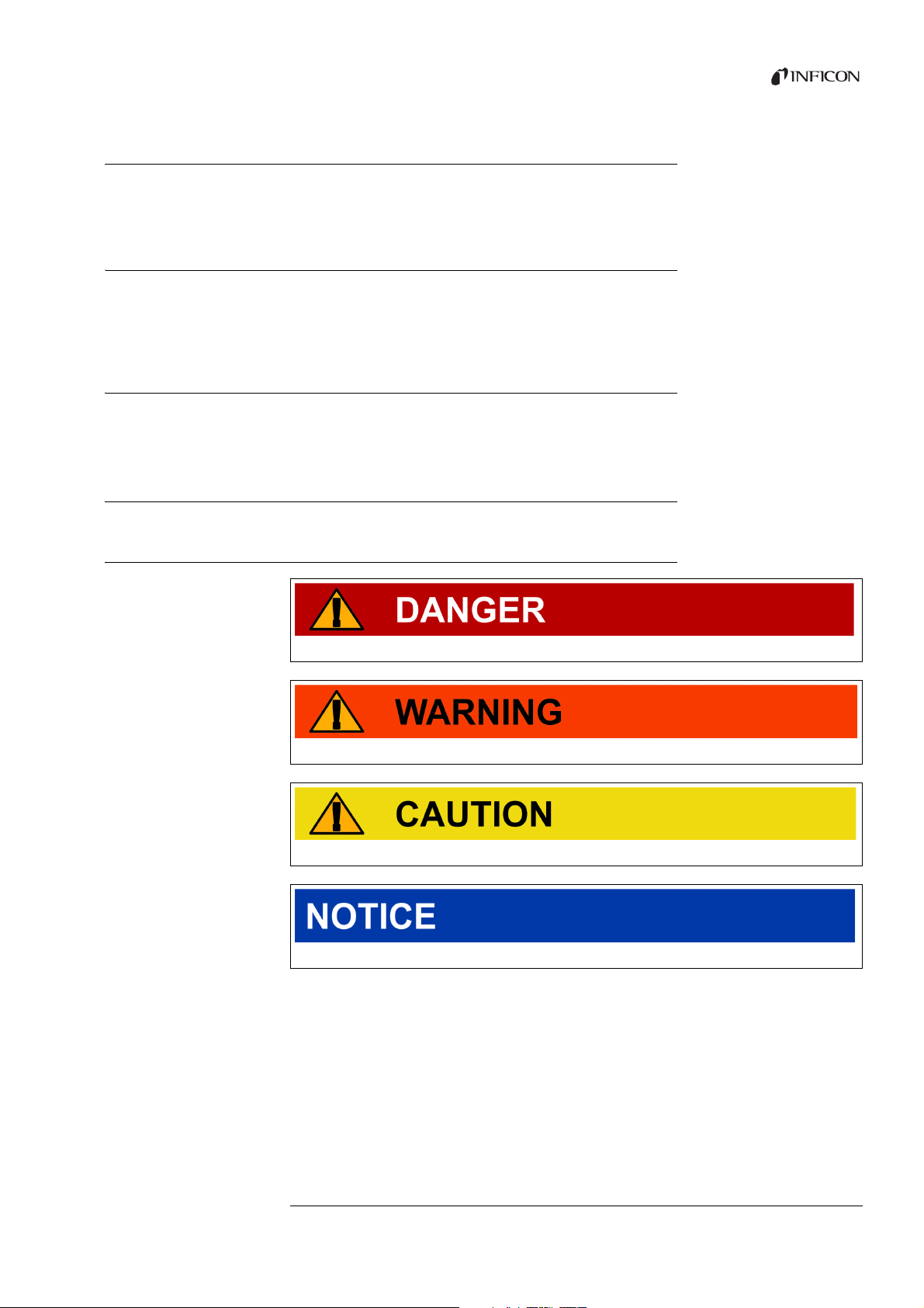
1.3.1 Warnings
Imminent threat of danger resulting in death or severe injuries
Dangerous situation potentially resulting in death or severe injuries
Dangerous situation resulting in minor injuries
Dangerous situation resulting in damage to property or the environment
Translation of the original operating instructions Ecotec E3000, kina22en1- r, 1407
1 About this manual 5
Page 6

6 1 About this manual
Translation of the original operating instructions Ecotec E3000, kina22en1- r, 1407
Page 7

2Safety
2.1 Intended use
The device is a leak detector for sniffer leak detection. With the device you locate and
quantify leaks on test objects. The device sniffs for light gases, refrigerants and natural
gases.
The test objects must contain the gas under overpressure. The outsides of the test objects
are checked for escaping gas with a sniffer line (sniffing method).
The sniffer line is available as an accessory (see “10.1 Accessories”, page 77).
► You must install, operate and service the device only in compliance with these
► Adhere to the restrictions of use (see “4.4 Technical data”, page 14).
operating instructions.
Unauthorized use
► Do not suction in liquids with the device.
► Never hold the sniffer probe into liquids but sniff only for gases.
2.2 Owner requirements
Safety-conscious
operation
Personnel qualifications
► Operate the device only in technically perfect working order.
► Operate the device exclusively as specified, in a safety-conscious and hazard-conscious
manner and in compliance with these operating instructions.
► Fulfill the following regulations and monitor their compliance:
– Intended use
– Generally applicable safety and accident prevention regulations
– International, national and local standards and guidelines
– Additional provisions and regulations that are specific to the unit
► Use only original parts or parts approved by the manufacturer.
► Keep these operating instructions available at the equipment location.
► Allow only qualified technical staff to work with and on the device. The qualified
technical staff must have received training on the device.
► Allow personnel in training to work with and on the device only under the supervision
of trained qualified technical staff.
Translation of the original operating instructions Ecotec E3000, kina22en1- r, 1407
► Make sure that the authorized personnel have read and understood the operating
instructions and all other applicable documents (see “1.2 Other applicable documents”,
page 5), especially the information on safety, maintenance and repairs, before starting
work.
► Define responsibilities, authorizations and supervision of personnel.
2Safety 7
Page 8

2.3 Operator requirements
► Read, observe and follow the information in these operating instructions and the
working instructions created by the owner, especially the safety instructions and
warnings.
► Carry out any work only based on the complete operating instructions.
► If you have questions regarding operation or maintenance that you cannot find
answers for in these instructions, please contact the INFICON customer service.
2.4 Dangers
The unit was built according to the state of the art and the recognized safety regulations.
Nevertheless, improper use can result in danger to life and limb of the operator or other
persons and damage to the unit and other property.
Dangers due to electric
power
Dangers due to liquids
and chemical
substances
The device is operated with electrical voltages of up to 265 V. Touching parts where
electric voltage is applied can result in death.
► Disconnect the device from the power supply prior to any installation and maintenance
work. Make sure that the electric power supply cannot be reconnected unauthorized.
Touching live parts with the sniffer probe can result in death.
► Before starting the leak test, disconnect electrically operated test objects from the
power supply. Make sure that the electric power supply cannot be reconnected
unauthorized.
The device contains electric components that can be damaged from high electric voltage.
► Before connecting the device to the power supply, make sure that the supply voltage
specified on the device is the same as the local power supply.
Liquids and chemical substances can damage the unit.
► Adhere to the restrictions of use (see “4.4 Technical data”, page 14).
► Do not suction in liquids with the device.
► Never try to find toxic, caustic, microbiological, explosive, radioactive or other harmful
substances with the device.
Hydrogen and air form a highly explosive mixture.
► Use the device only outside of explosive areas.
Dangers due to strong
light irradiation
8 2Safety
► You may not smoke. Do not subject the device to open fire and avoid sparking.
Exposure of the eyes to LED light can lead to lasting eye damage.
► Do not look into the LEDs of the sniffer handle from a short distance or for a longer
period of time.
Translation of the original operating instructions Ecotec E3000, kina22en1- r, 1407
Page 9
3 Shipment, transport, storage
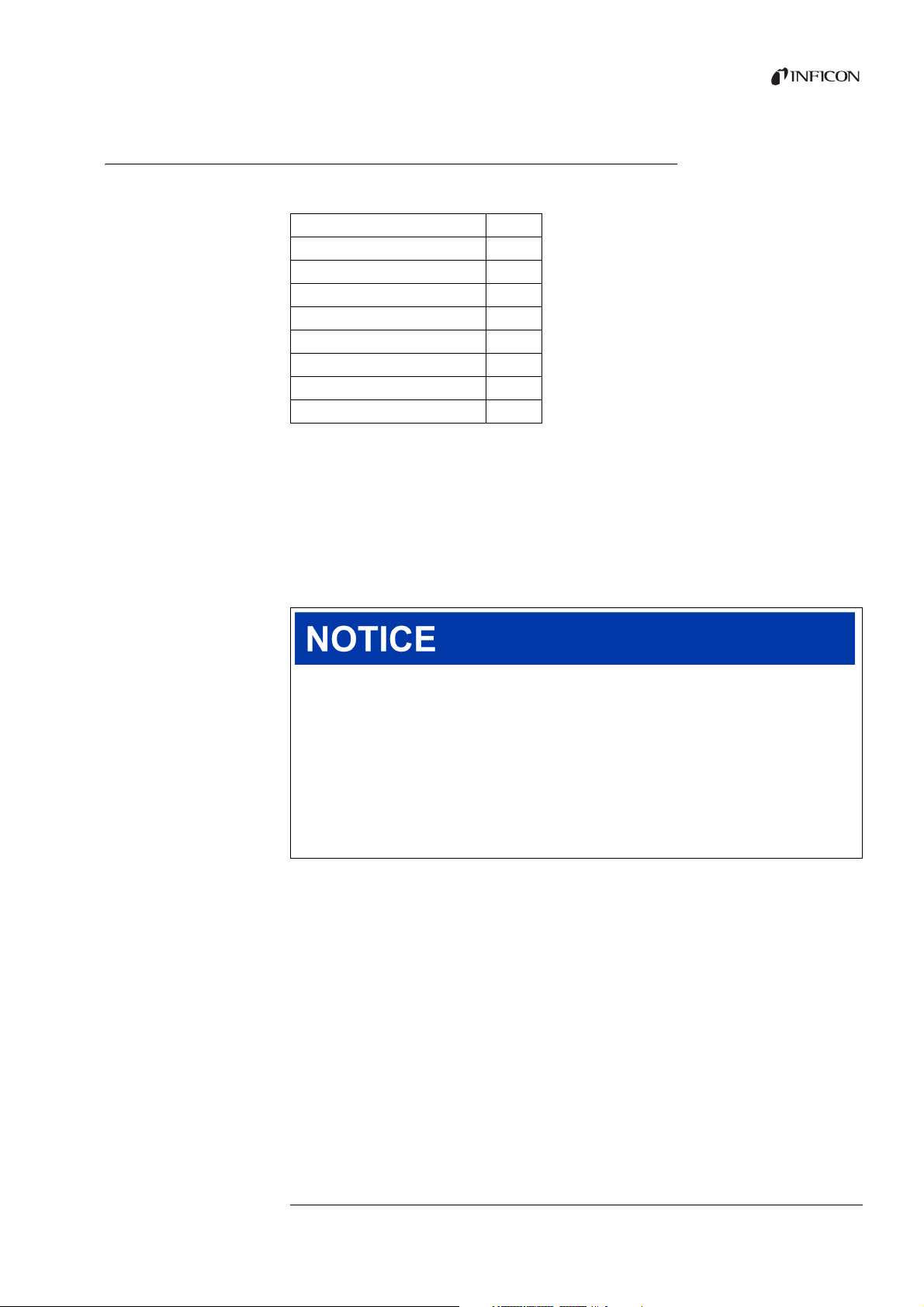
Scope of delivery
Tra ns por t
Table 1: Scope of delivery
Article Quantity
Ecotec E3000 (main unit) 1
Power supply cable, 3 m length 1
Fuses 30
Replacement air filter 1
8 mm Allen wrench 1
19 mm box wrench 1
Operating instructions 1
Interface description 1
► Check the scope of delivery of the product for completeness after receipt.
The following must be ordered separately:
sniffer lines with the desired length,
ECO-Check calibrated leak,
for device version E3000RC: display and connecting cable.
Accessory list: see “10.1 Accessories”, page 77
Damage from transport
Transport in unsuitable packaging material can damage the unit.
Parts inside the device can be damaged during transportation without transport
restraint.
► Store the original packaging.
► Transport the device only in the original packaging.
► Screw the transport restraint into the device floor before transportation, see
“5.1 Setup”, page 17.
Storage Store the device adhering to the specifications, see “4.4 Technical data”, page 14.
Translation of the original operating instructions Ecotec E3000, kina22en1- r, 1407
3 Shipment, transport, storage 9
Page 10

10 3 Shipment, transport, storage
Translation of the original operating instructions Ecotec E3000, kina22en1- r, 1407
Page 11
4 Description
a
c
b
d
b
e
4.1 Function and setup of the device
The Ecotec E3000 is comprised of main unit and sniffer line.
The Ecotec E3000 can verify and quantify gases sucked in by the sniffer line with the help
of a selective mass spectrometer.
Working in the Ecotec E3000:
a Quadrupol mass spectrometer as a detection system
a high vacuum pump system
an inlet system for the gas flow
electrical and electronic sub-assemblies for electrical supply and signal processing
The mass spectrometer works under high vacuum, i.e. the pressure in the mass
spectrometer must always be below 10
molecular pump with the help of a diaphragm pump.
4.2 Main unit
The main unit will be called “device” only in the following so long as this does not falsify
the meaning.
-4
mbar. This vacuum is created by the turbo
Translation of the original operating instructions Ecotec E3000, kina22en1- r, 1407
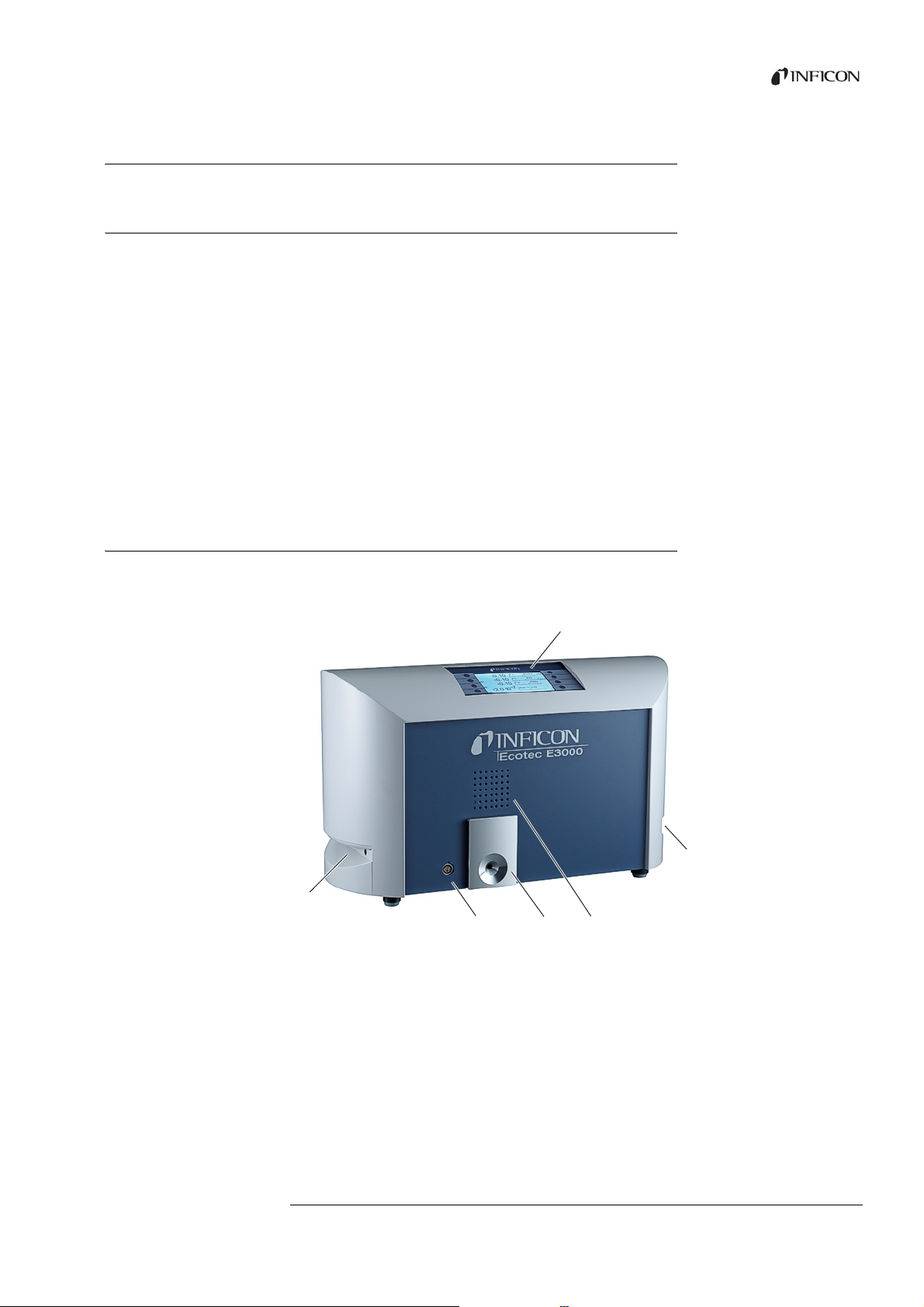
Fig. 1: Front view
a Display
b Handles and ventilation openings
c Speaker
d ECO-Check calibrated leak
e Lemo plug-in connector for sniffer line
4Description 11
Page 12

Fig. 2: Rear view
a cbefd
90001054694
530-001 Ecotec E3000
g
Headphone
I/O Port
RS-232
Sicherungen / Fuses 2 x 4 AT
a
Headphone connection, 3.5 mm jack
b Inputs/outputs (I/O port)
c RS-232 connection
e Fuses behind cover
f Power supply
g Rating plate
d Mains plug
a Headphone connection, 3.5 mm jack
In order to better hear signals in a loud environment, you can connect head phones.
b Inputs/outputs (I/O port)
The I/O port enables communication with a PLC. Some functions of the Ecotec E3000 can
be controlled from the outside and measurement results and device states of the Ecotec
E3000 can be transmitted to the outside.
Relay changeover contacts allow monitoring of the trigger values and the operating status
of the Ecotec E3000. Please refer to the “Interface description Ecotec E3000” (doc. no.
kins22e1) for further information.
c RS-232 connection
A PC can read out all data and measurement results of the device and control the device
via the RS-232 connection. Please refer to the “Interface description Ecotec E3000” (doc.
no. kins22e1) for further information.
d Mains plug
The mains plug serves to switch the device on and off.
e Fuses behind cover
For information on replacing the fuses, see “8.2.3 Replacing mains fuses”, page 71.
f Power supply
For information on the power supply, see “4.4 Technical data”, page 14, as well as the
labeling on the power supply (rating plate).
Translation of the original operating instructions Ecotec E3000, kina22en1- r, 1407
12 4Description
Page 13
4.3 Sniffer line
90001054694
530-001 Ecotec E3000
a
b
c
a
c
b
e
d
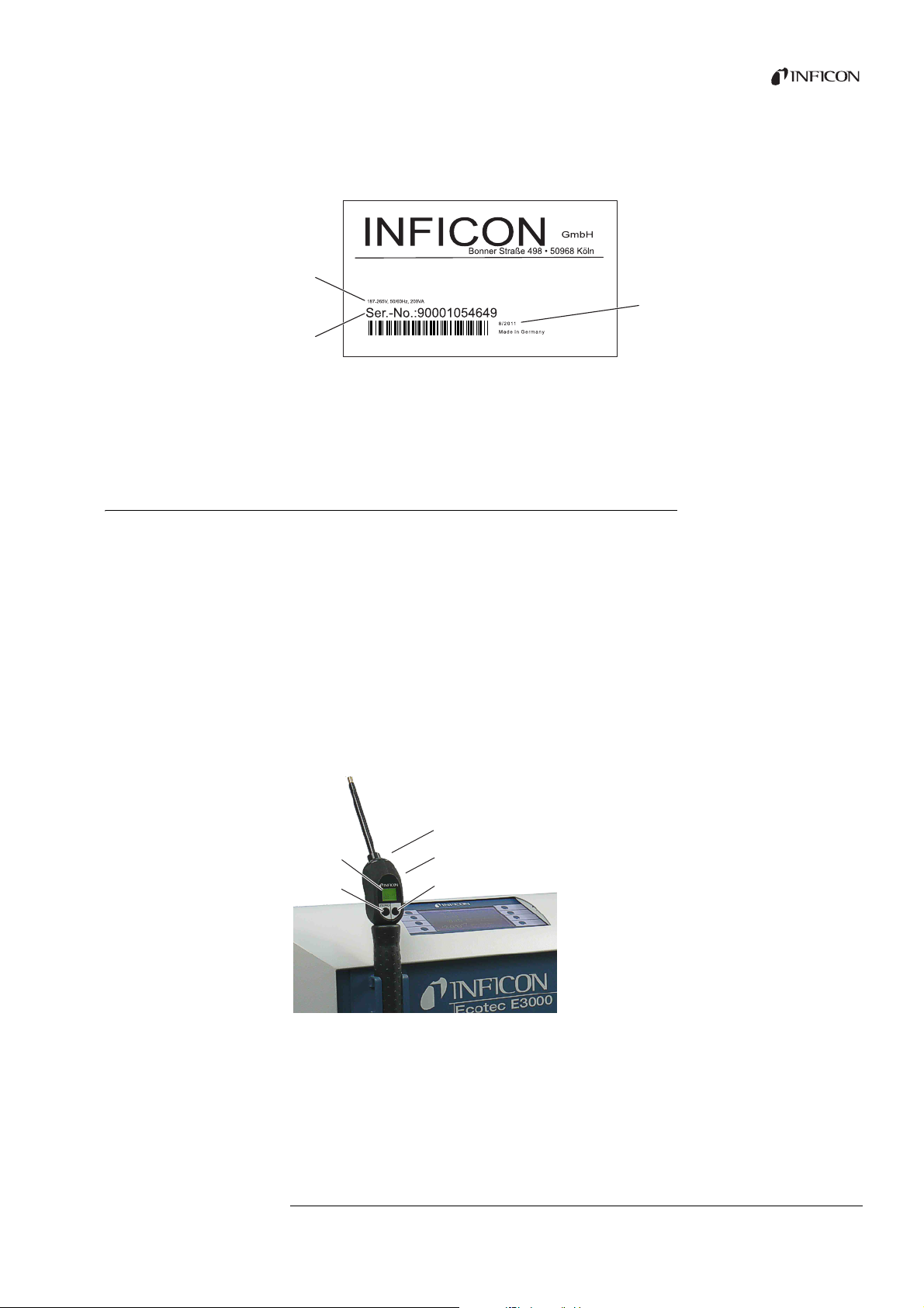
g Rating plate
The rating plate contains the supply voltage specification and other information with
which the device can be clearly identified.
Fig. 3: Rating plate
a Supply voltage
b Serial number
c Production date
You need a sniffer line to operate the device. Sniffer lines are available in four lengths: 3 m,
5 m, 10 m and 15 m.
The sniffer line is made of a flexible tube (multi-function cable), a handle with controls
(sniffer handle) and a sniffer probe.
There is a special sniffer line for robotic applications (see “10.1 Accessories”, page 77).
Sniffer probe There are rigid and flexible sniffer probes with different lengths.
Sniffer handle display
and functions
The display on the sniffer handle shows current information on the measuring process.
You can operate functions frequently used during measurement with both buttons.
LEDs inserted in the handle illuminate the test area.
Fig. 4: Handle: display and functions
a Display
b ZERO adjustment
d Speaker (on the rear)
e I•Guide operation
c LEDs
Translation of the original operating instructions Ecotec E3000, kina22en1- r, 1407
4Description 13
Page 14

If the measuring value limit is exceeded, the display switches from green to red. You can
additionally set one speaker in the handle to output a signal and the LEDs in the handle to
flash or shine with maximum brightness, see “6.3 Settings before measurements”, page 28.
4.4 Technical data
Table 2: Technical data
Mechanical data
Dimensions (W H D) 610 mm 370 mm 265 mm
Wei ght 34 kg
Ambient conditions
Permissible ambient temperature (during operation) 10 °C to 45 °C
Permissible storage temperature -20 °C to 60 °C
Max. relative humidity up to 31 °C 80 %
Max. relative humidity from 31 °C to 40 °C Linearly dropping from 80 % to 50 %
Max. relative humidity above 40 °C 50 %
Pollution degree II
Max. altitude above sea level 2000 m
Electrical data
Supply voltages and frequencies Country-specific, see rating plate on device rear
Power consumption 300 VA
Protection class IP 20
Overvoltage category II
Mains fuse 2 4 A slow-blow
Power supply cable 2.5 m
Noise level < 54 dBA
Physical data
Minimum detectable leak rate
Measurement range 6 decades
Detectable masses 2 to 200 amu
Mass spectrometer Quadrupol mass spectrometer
Ion source 2 cathodes
Time constant of the leak rate signal < 1 s
Gas flow through the capillary
Measured at 1 atm (1013 mbar) at sea level. The flow rate
changes with geographical height and barometric pressure.
Time until ready for operation < 2 min
(according to IEC 61010/part 1: “Usually, only nonconducting soiling may occur. However, temporary
conductivity caused by condensation is tolerable at times.“)
R134a 0.05 g/a (0.002 oz/yr)
R600a 0.05 g/a (0.002 oz/yr)
Helium < 1 10
-6
mbar l/s
120 to 200 sccm
14 4Description
Translation of the original operating instructions Ecotec E3000, kina22en1- r, 1407
Page 15

Translation of the original operating instructions Ecotec E3000, kina22en1- r, 1407
Table 2: Technical data (cont.)
Response time
3 m sniffer line 0.7 sec.
5 m sniffer line 0.9 sec.
10 m sniffer line 1.4 sec.
15 m sniffer line 3.0 sec.
Table 3: Factory settings
Alarm profile Trigger alarm
Alarm delay Deactivated
Number of measuring points (I•Guide) 4
Functions Activated
Internal Activated
Recording output Auto
Baud rate and blank flange 9600 CR+LF
Pressure unit mbar
Flow rate
Lower limit 100 sccm
Upper limit 250 sccm
Sensitivity test Activated
Gas, definition Gas 1, gas 2, gas 3, gas 4, gas 5, gas 6
Device speaker Activated
Handle speaker Trigger value
Selecting a cathode A
I•Guide Deactivated
Calibration (cal), internal Activated
Contrast Not inverted, setting 30
Vol ume 2
Minimum volume 2
Leak rate, selected, highest Automatic
Leak rate filter I•Filter
Menu PIN Deactivated, 0000
Measuring time (I•Guide) 1 second
Measuring mass 69
Peak value Deactivated, 5 seconds
ECO-Check Activated
Relay outputs See interface description
RS-232 protocol ASCII
Sniffer probe, light Activated, Level 4
Sniffer probe, filter, maintenance 100 hours
Recorder, gas Auto
Scaling of the recorder Logarithmic
Language English
SPS outputs and inputs See interface description
4Description 15
Page 16

Table 3: Factory settings (cont.)
Control location Local and RS-232
Search threshold 90 %
Tri gge r va lue , su m (I •Gui de) 10 g/ a
Trigger and unit 4 g/a
Idle time (I•Guide) 3 seconds
Maintenance, sniffer probe filter 100 hours
Zero time 5 seconds
Zero key sniffer line Activated
ZERO key main unit Activated
16 4Description
Translation of the original operating instructions Ecotec E3000, kina22en1- r, 1407
Page 17
5 Installation
5.1 Setup
Danger due to moisture and electricity
Moisture getting into the device can lead to personal injury from electric shocks and to
material damage from short circuits.
► Operate the Ecotec E3000 only in a dry environment.
► Operate the Ecotec E3000 away from sources of liquid and moisture.
Danger due to dropping heavy loads
The device is heavy and can damage persons and items through tilting or dropping.
► Place the device only on a sufficiently sturdy surface.
Material damage due to vibration.
Parts of the measurement technology rotate and must not be shaken. The parts continue
to rotate for several minutes after the device is shut down.
► Place the device only on a sturdy, vibration-free surface.
► The device must not be shaken during operation and at least five minutes after being
switched off.
Material damage due to an overheated device
The device heats up during operation and can overheat without sufficient ventilation.
► Please note the specifications, see page 14.
► Ensure sufficient ventilation especially on the ventilation openings on the left and
right of the device: free space on the side at least 20 cm, in front and in the rear at least
10 cm.
► Keep heat sources away from the device.
► Do not subject the device to direct sunlight.
Translation of the original operating instructions Ecotec E3000, kina22en1- r, 1407
5Installation 17
Page 18
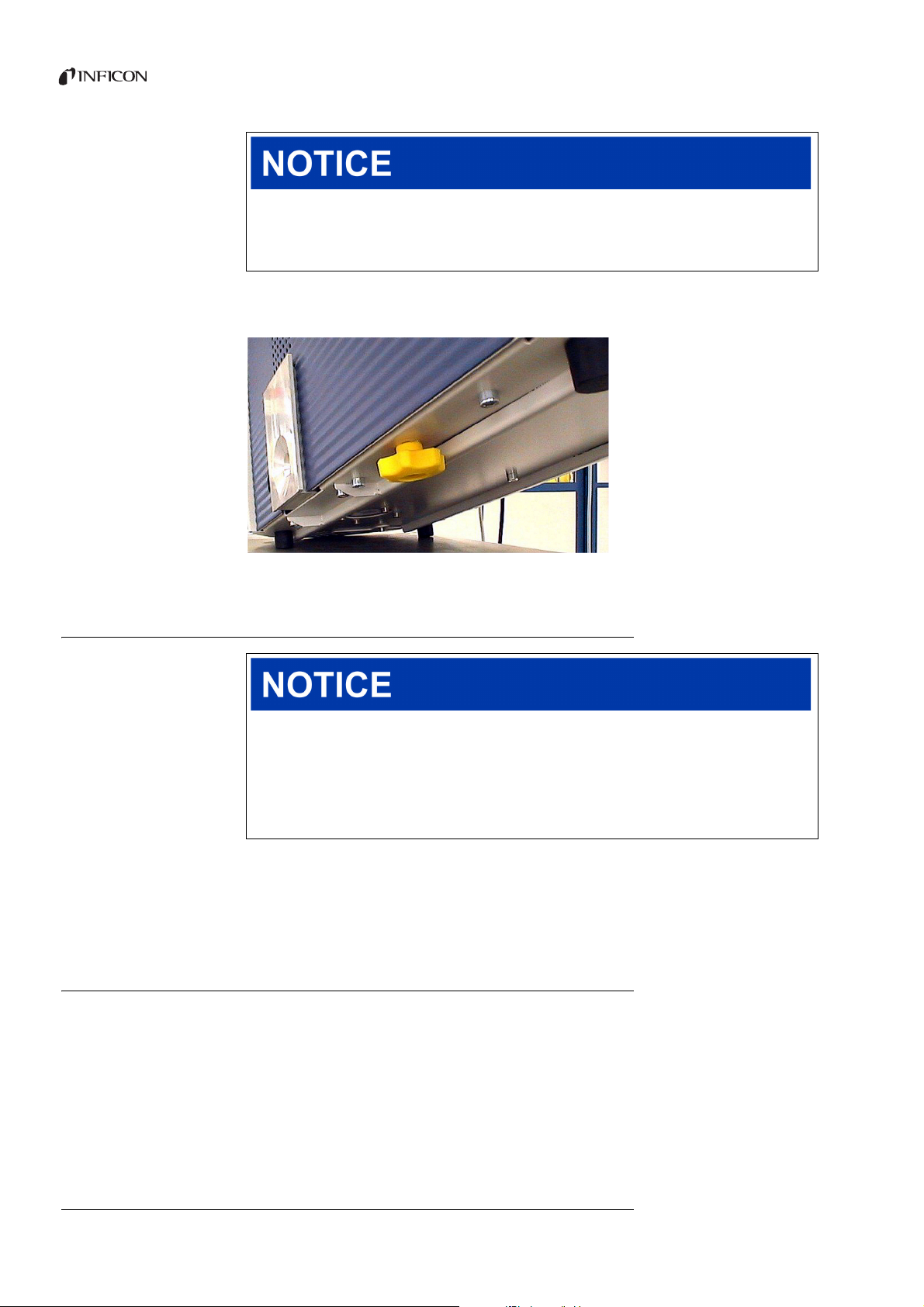
Material damage due to transport restraint that has not been removed
The transport restraint blocks the mechanical system in the device.
► Remove the transport restraint before the start-up.
The transport restraint is on the bottom of the Ecotec E3000 and consists of a yellow star
screw.
Fig. 5: Unscrew the yellow transport restraint before the start-up
5.2 Connecting the sniffer line
Material damage due to a missing sniffer line
The device must not be operated without a connected sniffer line in order to avoid
overpressure in pump and measurement system.
► Connect the sniffer line before you start up the device.
► Do not replace the sniffer line while the device is in operation.
Align the red marking on the sniffer line plug with the red marking on the socket. Push the
sniffer line plug into the socket on the device until it locks into place.
Pull the grooved ring on the plug to release it. The ring opens the lock and you can pull out
the plug.
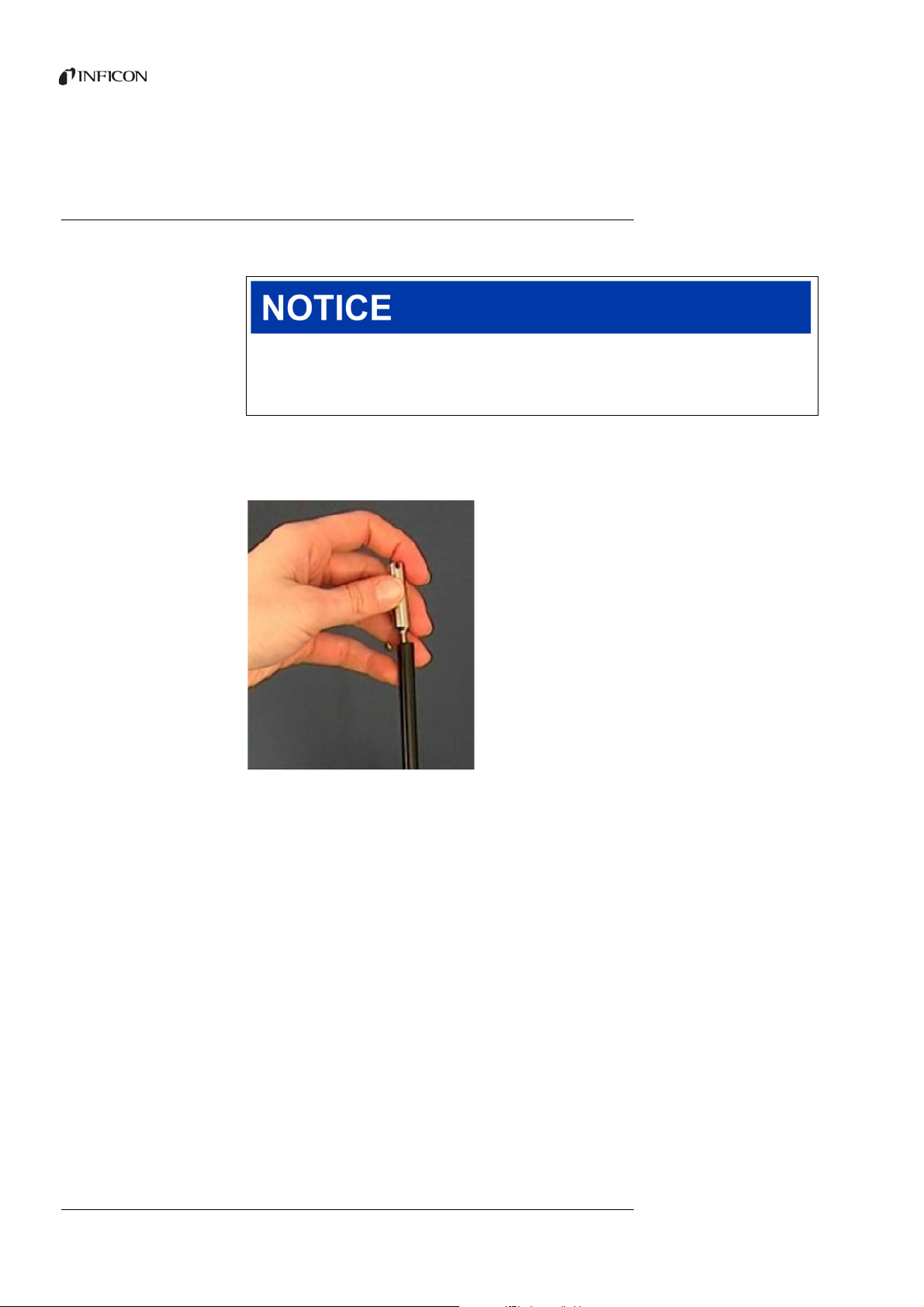
5.2.1 Replacing the capillary filter of the sniffer probe
The metal capillary filter is the standard filter. With the plastic capillary filter there is less
danger of scratching the surfaces to be sniffed. The water conservation tip is used if there
is a danger of suctioning in liquids.
Translation of the original operating instructions Ecotec E3000, kina22en1- r, 1407
18 5Installation
Page 19
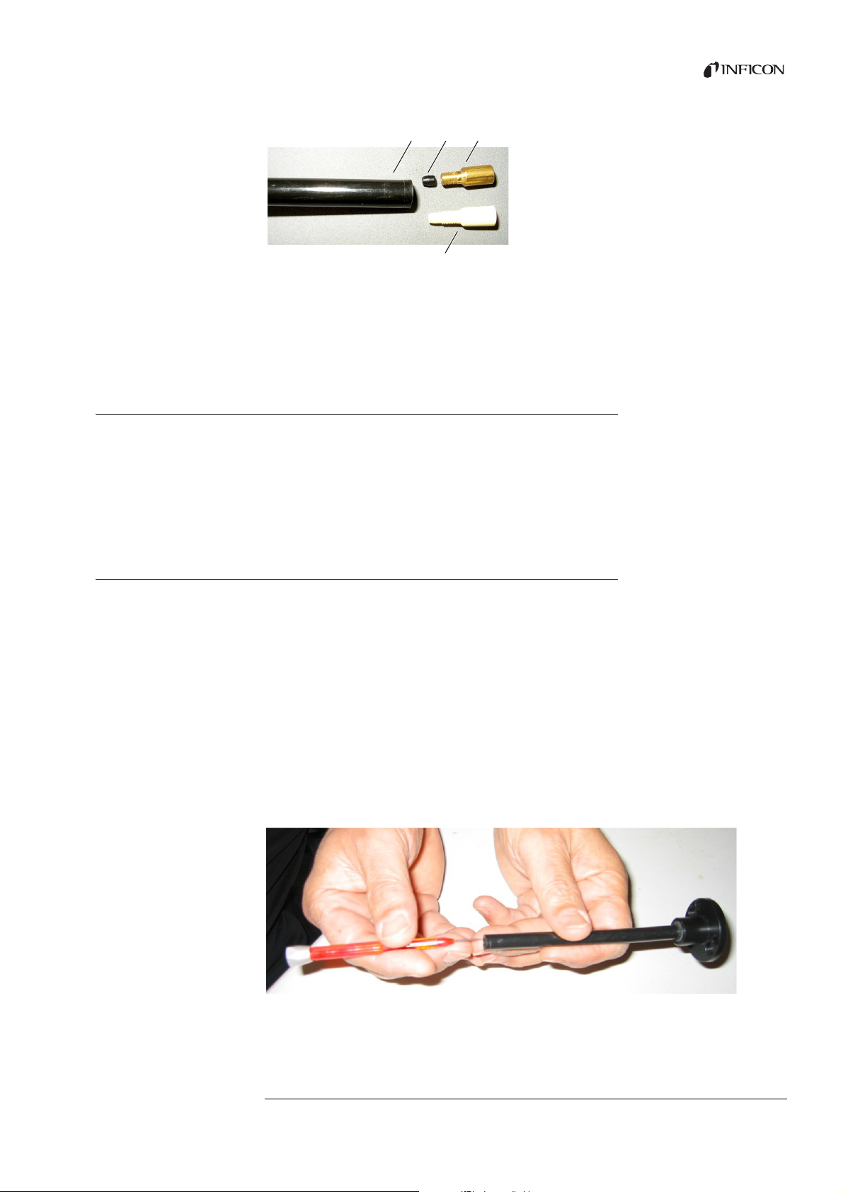
Fig. 6: Capillary filter
abc
d
a Sniffer probe end
b Plugwasher
c Metal capillary filter
d Plastic capillary filter
5.2.1.1 Replacing the plastic capillary filter with the metal capillary filter
1 Turn off the Ecotec E3000.
2 Unscrew the plastic capillary filter.
3 Insert the plugwasher, see fig. 6 on page 19.
4 Screw in the metal capillary filter on the sniffer probe end.
5 Calibrate the Ecotec E3000, see “6.4.2 Calibration”, page 37.
5.2.1.2 Replacing the metal capillary filter with the plastic capillary filter
If you want to switch from a capillary filter made of metal to a capillary filter made of
plastic, you have to the remove the plugwasher. The plugwasher sits on the steel capillary
in the sniffer probe.
1 Turn off the Ecotec E3000.
2 Unscrew the filter.
Translation of the original operating instructions Ecotec E3000, kina22en1- r, 1407
3 Unscrew the two cross-head screws in the sniffer probe flange and take out the sniffer
probe.
4 Push the capillary out of the plastic sheath a bit from the top with a narrow pin or a thin
needle (about 0.5 mm). Make sure that the sinter filter in the sniffer probe flange does
not get lost in doing so
5 Remove the plugwasher from the sniffer probe.
Fig. 7: Pushing out the capillary
6 Put the sinter filter back in and tighten the sniffer probe on the handle.
5Installation 19
Page 20
7 Screw the plastic capillary filter on the sniffer probe.
8 Calibrate the Ecotec E3000, see “6.4.2 Calibration”, page 37.
5.2.1.3 Water conservation sniffer probe mounting and remove
With the help of the water conservation sniffer probe, you can check test objects with low
surface moisture, e.g. condensation moisture, for tightness.
Short circuit hazard
Sucked in liquid can destroy the device.
► Do not suction in liquids with the device.
The water conservation sniffer probe is screwed onto the sniffer probe end like the metal
capillary filter. The small plugwasher must also be placed below the end, see
“5.2.1.2 Replacing the metal capillary filter with the plastic capillary filter”, page 19.
20 5Installation
Fig. 8: Tightening the water conservation sniffer probe
For renewed mounting of the plastic capillary filter, see “5.2.1.1 Replacing the plastic
capillary filter with the metal capillary filter”, page 19.
Translation of the original operating instructions Ecotec E3000, kina22en1- r, 1407
Page 21
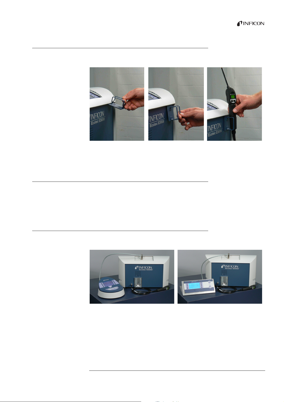
5.2.2 Attaching the sniffer lines holder
A holder is available for the sniffer probe. The holder can be installed on the right or the
left of the device.
Fig. 9: Sniffer line holder mounting
The holder has two hooks that are inserted into two slits on the front panel of the device.
The holder is pulled to the front panel of the device with a magnet on its rear.
5.3 Connecting the ECO-Check calibrated leak
A built-in calibrated leak (ECO-Check) and different external calibrated leaks are available
as accessories available for the Ecotec E3000, see “10.1 Accessories”, page 77.
Please refer to the ECO-Check installation manual on how to connect the ECO-Check.
5.4 Connecting the external display unit to the Ecotec E3000RC
Connect the external display unit and the Ecotec E3000RC with the appropriate
connecting cable. Secure the plug on the socket by tightening the screws.
Fig. 10: The Ecotec E3000RC with external display unit as a table device (left), for rack mounting (right)
Translation of the original operating instructions Ecotec E3000, kina22en1- r, 1407
5Installation 21
Page 22
5.5 Connecting to the power supply system
The supply voltage of the Ecotec E3000 is specified on the labeling of the mains plug
(rating plate). The Ecotec E3000 cannot be switched for other supply voltages.
Danger due to incorrect supply voltage
Incorrect supply voltage can destroy the device and injure persons.
► Check whether the supply voltage specified on the Ecotec E3000 matches the supply
voltage available on site.
Connect the device to the electric power supply with the supplied power cable.
5.5.1 Connecting to a PC
The connection is made with a commercially available 9-pin SUB-D plug. Please refer to
the “Interface description Ecotec E3000” (doc. no. kins22e1) for further information on
data exchange.
5.5.2 Connecting with a PLC
The connection is made with a commercially available 25-pin SUB-D plug.
Please refer to the “Interface description Ecotec E3000” (doc. no. kins22e1) for further
information on data exchange.
22 5Installation
Translation of the original operating instructions Ecotec E3000, kina22en1- r, 1407
Page 23
6Operation
Start screen in EN
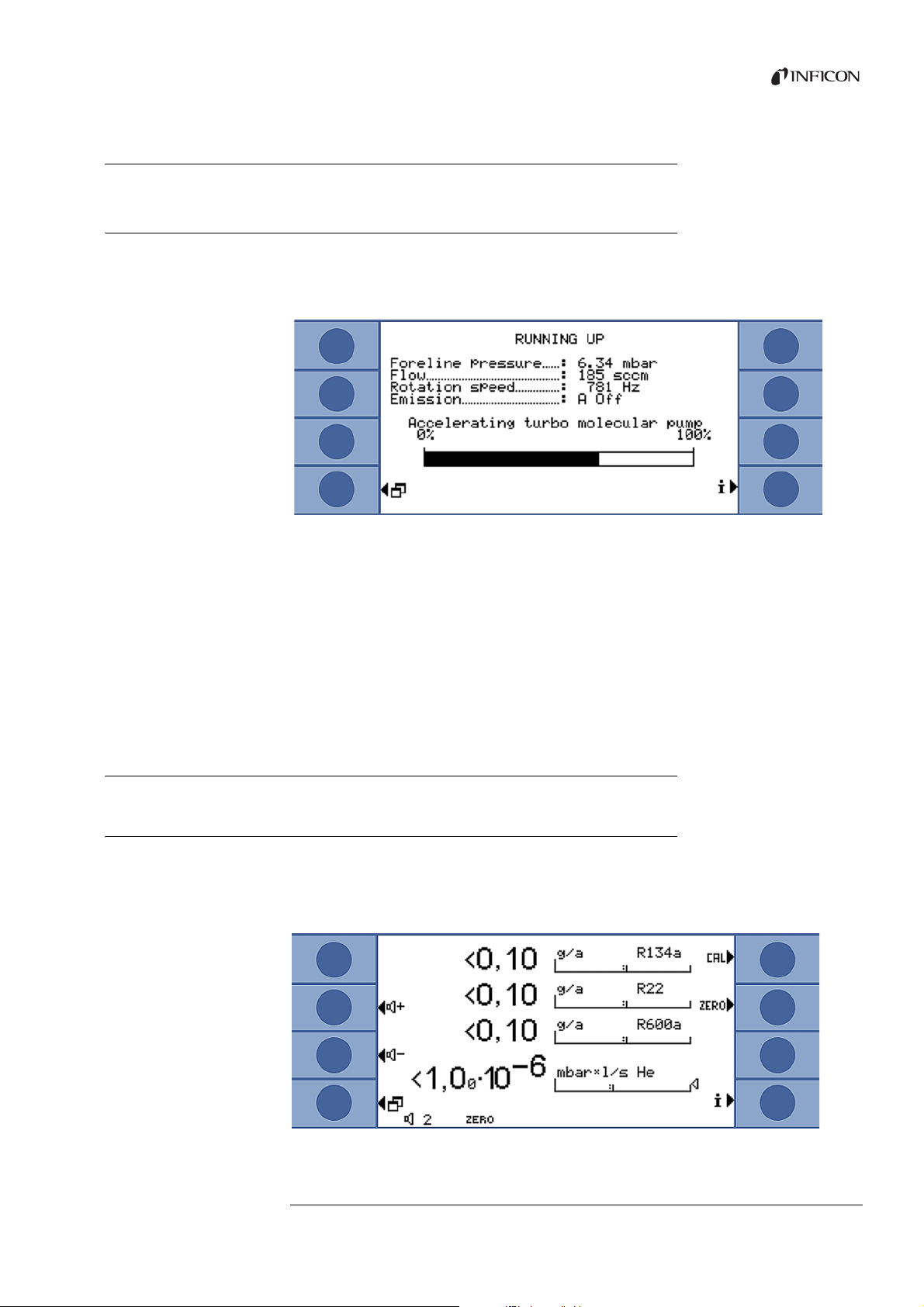
6.1 Start-up
Connect a sniffer line and switch on the device with the mains plug.
The Ecotec E3000 starts a self-test lasting several minutes. The display shows the headline
“Running up” and the individual steps of the self-test.
Fig. 11: The device runs up
After running up, the Ecotec E3000 already measures the gas concentration in the
environment. There is no separate start function. But you have to still calibrate the device
and make different settings for your intended measurement.
If the ECO-Check calibrated leak is not in the Ecotec E3000, an acoustic warning signal and
the warning 71 are output during the first start-up.
To stop the alarm quickly, press the key on the bottom right (labeled “OK“). If you are
working without the ECO-Check, you should deactivate the alarm permanently, see “ECO-
Check”, page 34.
6.2 Operating the device
6.2.1 Display and keys
All settings are made with the eight keys to the left and the right of the display. The
function allocations of the keys change depending on the current operating step. The
function allocation is shown directly next to the key which allows fast and purposeful
operation after a short learning period.
Translation of the original operating instructions Ecotec E3000, kina22en1- r, 1407
Fig. 12: Start display after the self-test
6Operation 23
Page 24
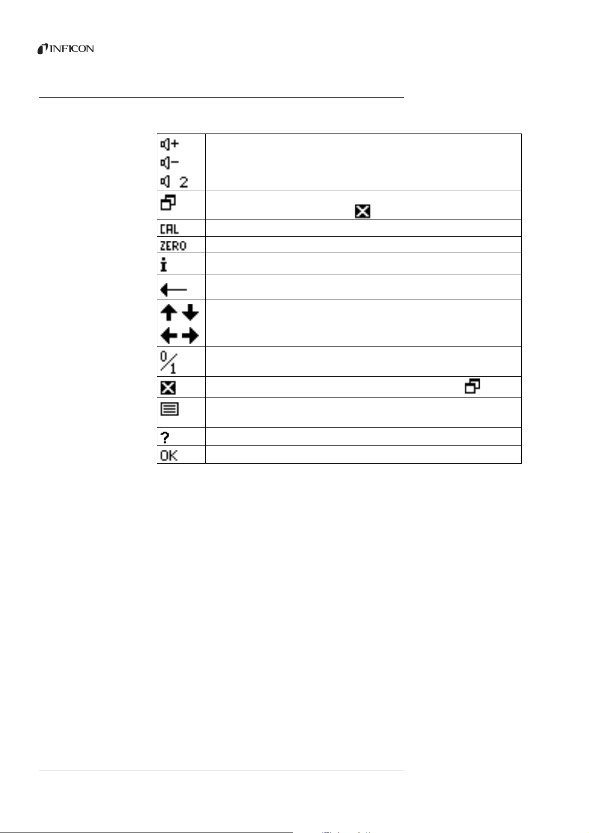
6.2.1.1 Recurring function symbols
Back
The keys are always assigned with the following functions and labeled with the shown
symbols.
Setting the volume for speakers and head phones.
Set volume: The set volume is displayed on the bottom edge of the display.
Value range: 0 (off) to 10 (max.)
– Calling the main menu.
– Calling a window again that was closed with .
Calling up calibration.
The lower edge of the display shows “Zero” if a zero point has been set since the device start-up.
Calling up information: software version, operating hours, serial number, date & time, alarm profile.
Back to last menu level.
Navigating in a list box.
Pressing the key assigns the allocation “0” to that key and “1” to an adjacent key. The same setting option
exists for the numbers “2/3”, “4/5”, “6/7”, and “8/9”.
Closing the window and calling up the measurement view. Back to the window with
– Calling up the list of gases.
– Measurement with I•Guide: calling up the list of I•Guide programs.
Calling up help for the current function.
Confirming an entry or selection.
24 6 Operation
Translation of the original operating instructions Ecotec E3000, kina22en1- r, 1407
Page 25
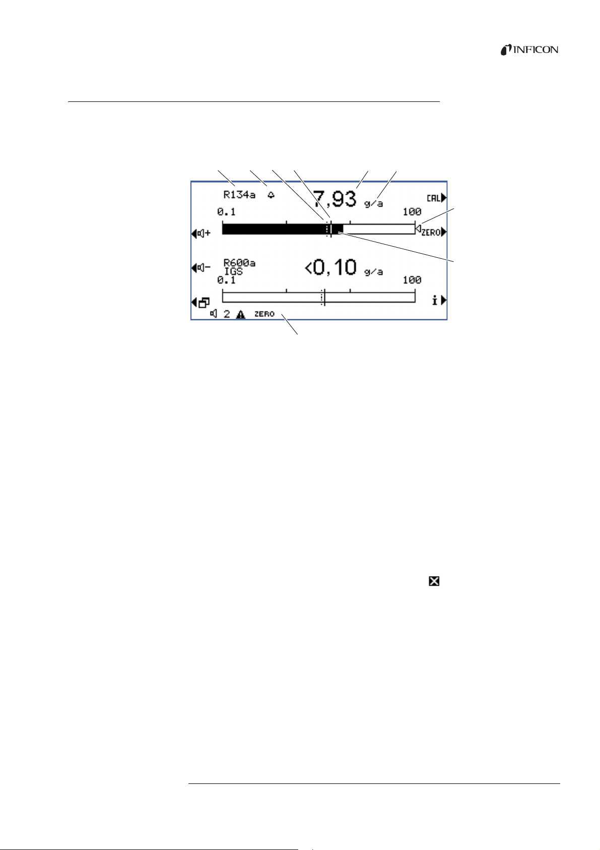
6.2.2 Elements of the measurement view
a b c d
g
e f
i
h
The measured leak rates are shown numerically and with logarithmically divided bar
graph displays.
The other elements of the measurement view are shown in the following figure.
Fig. 13: Elements of the measurement view
a
Gas
b Bell: search threshold exceeded; flashing bell:
trigger value exceeded
c Search threshold (broken line)
d Trigger value
e Numerical leak rate display
f Leak rate unit
g Marking arrow: marks the measurement
displayed on the sniffer handle
h Bar graph, logarithmic
i Status bar: symbols and text overlay provide
information about the device status
The two center keys on the left side of the display can be used to adjust the volume of the
alarm signal at any time. If one of the two keys is pressed, the device emits a sound with
the selected volume through the speaker and shows the setting with a bar graph in the
status line. The set value is also the first entry in the status line on the bottom of the display
and applies only to the speaker of the main unit. To adjust different alarm profiles, see
page 29.
Menu key
The key on the bottom left of the display has two functions:
Calling the main menu.
Returning you to the last window that was closed with .
Calibration key (CAL)
The key on the top right next to the display can be used to start a calibration of the Ecotec
E3000 with an external test leak at any time. Additional information on completing an
external calibration, see “6.4.2.2 External calibration with external calibrated leak”,
page 39.
ZERO key
Pressing the ZERO key briefly stores the currently displayed leak rate as zero point for all
selected refrigerants. Pressing the ZERO key for more than 2 seconds switches off the
ZERO function. The display ZERO disappears from the status line in this case. For more
information on the ZERO function, see “Zero”, page 31.
Translation of the original operating instructions Ecotec E3000, kina22en1- r, 1407
6Operation 25
Page 26
Information key
a
b
c
d
e
2.0E-7
HE
Pressing the information key
the status of the Ecotec E3000. Details: see “6.4.6.1 Calling up information on the
measurement”, page 45.
Status line
Status information is displayed in the lower line of the measurement window. The set
volume for the alarm is displayed in the left of the line.
If the small speaker flashes, it indicates that the device speaker is switched off.
If the number flashes, it indicates that the alarm delay is switched on, see “Alarm delay”,
page 29
A small black triangle with an exclamation point next to it can indicate an active warning.
If the ZERO function is activated, the word “ZERO” follows in the status line.
If the first cathode (filament A) of the mass spectrometer has been consumed and the
Ecotec E3000 switches automatically to the second cathode (filament B), the display will
show “Fil. B” in the status line.
If you working with an activated IGS, “IGS” will be shown in the status line.
i (to the bottom right of the display) shows information on
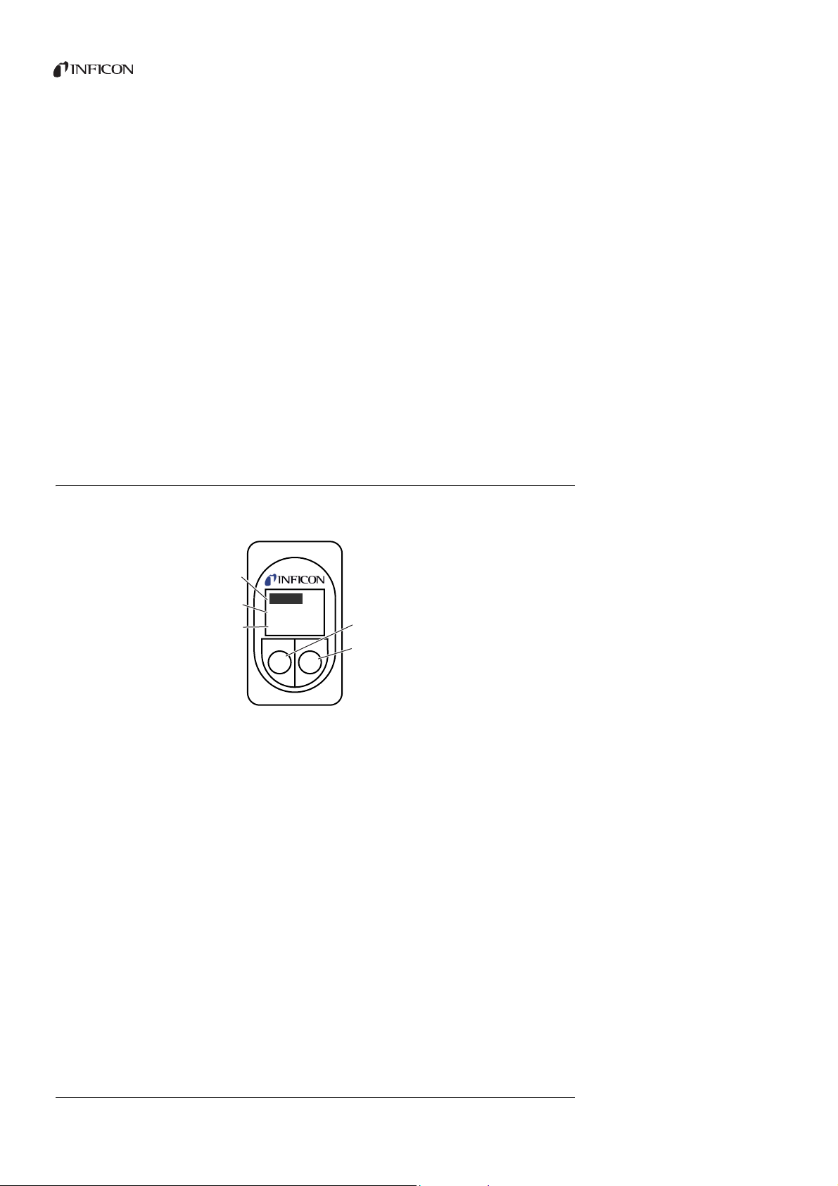
6.2.3 Operating elements and display on the sniffer handle
The display of the sniffer handle shows the most important information for the current
measurement. Measurements can be controlled with the two keys.
26 6 Operation
Fig. 14: Operating elements and display on the sniffer handle
a Leak rate as bar graph
b Leak rate, numerical. Unit, as shown on the main unit
c Measured gas
d Left key, assigned “Zero”
e Right key, different assignments
The measured leak rate is shown as an increasing or decreasing bar. The second line shows
the leak rate as a numerical figure (with the same measurement unit as in the main
display). The third line shows the abbreviation for the measured gas.
Depending on the measurement, the display can also show something else, e.g. “Error” or
the number of a warning.
If you search for several gases simultaneously, you can switch between individual
measurement results with the right key. The right key can also be used to confirm
messages or states during a measurement cycle.
You can trigger the ZERO function with the left key, see “Zero”, page 31.
Translation of the original operating instructions Ecotec E3000, kina22en1- r, 1407
Page 27
The key can be deactivated to prevent accidental triggering: Press the key until you hear a
signal. The key is reactivated by pressing it longer.
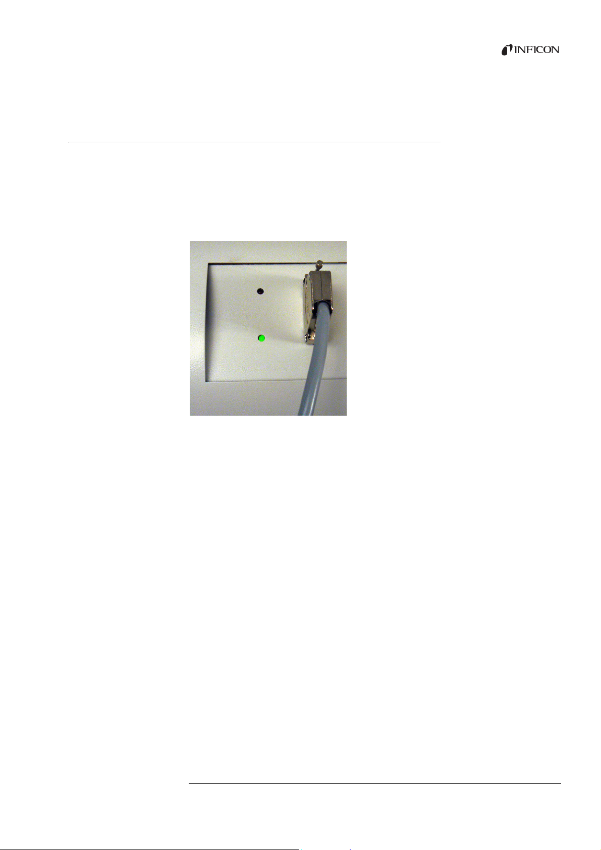
6.2.4 Special features of the Ecotec E3000RC
The Ecotec E3000RC has a connection panel for the external display unit instead of the
built-in display. Two LEDs (to the left of the plug) provide information on the status of the
Ecotec E3000RC, even if the external display unit is not connected.
The green LED shows that the Ecotec E3000RC is switched on. It has a steady green light if
an external display is connected and flashes if no external display can be detected.
The red LED flashes in case of an error message; a steady red light indicates a warning.
Fig. 15: Connection panel with LEDs
If no display unit is connected, you can confirm error messages and warnings by pressing
both keys on the sniffer line simultaneously.
The external display unit has four keys:
The menu key opens the main menu.
The current measured background value is set as zero point with the ZERO key, see
“Zero”, page 31.
The START / STOP keys do not have any function (the external display unit can also be
used with other leak detectors made by INFICON that require these keys).
Translation of the original operating instructions Ecotec E3000, kina22en1- r, 1407
6Operation 27
Page 28

6.3 Settings before measurements
Before the first measurements, you should make different device settings in the following
menus:
Miscellaneous
Display
Audio
Vacuum & access control
Interfaces (for control via interfaces and if you use an ECO-Check)
You can access the menus via the main menu
6.3.1 Miscellaneous
Language You can select one of the following languages:
English (factory setting)
German
French
Italian
Portuguese
Spanish
Japanese (Katakana)
Chinese (Mandarin, simplified Chinese)
To set the language to English temporarily, press keys two and six during the run-up of the
Ecotec. Call up the language setting after the run-up and set the required language.
Time & Date First page: internal date with the format DD.MM.YYYY
Second page (press key on the bottom right ) time with the format SS:MM.
Sniffer light Activate/deactivate light
Adjust brightness from 1 (min) to 6 (max)
Pressure unit atm
Tor r
Pa
mbar
Leak rate filter Auto
Fixed
I•Filter
The I•Filter is an intelligent filter algorithm that delivers the best results regarding
interference suppression and stability of the leak rate signal. It was especially developed
for the use in the Ecotec E3000.
Only in cases in which the older Ecotec II model was replaced with an Ecotec E3000 and
the Ecotec E3000 is used in a fixed test device can it be necessary to select the older filter
settings “Auto” or “Fixed”.
28 6 Operation
Translation of the original operating instructions Ecotec E3000, kina22en1- r, 1407
Page 29

Alarm delay With very unstable surface conditions, it can be expedient to emit an acoustic alarm only
if the trigger value is exceeded for a specified period of time. If the function is activated,
the number indicating the volume of the device speaker flashes in the status bar.
Setting range: 0 to 9.9 seconds, in tenths of a second
Danger due to undetected leaks.
If the alarm delay is activated, there may be no acoustic alarm even though a leak is
detected.
► Please note the measurement display in the device and the handle.
► Deactivate the function when surface conditions are stable again.
Wake up If the Ecotec E3000 is in idle state (sleep), a time can be set for it to start automatically. This
way you can set the Ecotec up to run through its warm-up phase already before the shift
starts.
You can set a separate wake-up time exact to the minute for each day of the week.
To deactivate the wake up again, set the wake-up time to 00:00.
6.3.2 Audio settings
Beep sound You can switch off the signals that indicate the completion of specific functions.
Device speaker You can switch off the speaker installed in the main unit. This does not influence the
speaker connection.
Audio sniffer You can choose whether the speaker in the sniffer handle should signal the exceedance of
search threshold or trigger value.
You can also switch off the speaker completely.
Alarm profile You can assign one of three alarm profiles to the device speaker:
Pinpoint
Setpoint
Trigger/alarm
Translation of the original operating instructions Ecotec E3000, kina22en1- r, 1407
6Operation 29
Page 30

Table 4: Features of the alarm profiles
Alarm profile pinpoint Alarm profile setpoint Alarm profile trigger/alarm
Search value exceeded – Acoustic signal low frequency Acoustic signal low frequency
Trigger value exceeded – Acoustic signal high
Two-tone signal
frequency
Acoustic tracing of the
measurement result
< 1/10 trigger value: low frequency – –
>1/10 trigger value up to 10 trigger value:
rising frequency
> 10 trigger value: high frequency
Comment Recommended, for precise leak localization – Three different two-tone signals
available for selection.
This allows identification with a signal for
devices that are used together.
Volu me You can adjust the volume that cannot be set lower with the plus and minus keys next to
the display. This way you can prevent the acoustic signals from being switched off
accidentally during the measurement.
The adjustment applies to the speaker in the main unit and the head phones.
You can also set the current volume of speaker and head phones here.
Setting range: 0 to 15
Hearing damage from excessively loud signals
The volume of signals can exceed 85 dB(A).
► Keep away from the device if the volume has been set to high.
► Wear ear protection, when needed.
6.3.3 Display settings
In the menu “Settings > Display”, you can set the display details of the device display and
the display in the sniffer handle.
Contrast Increase or decrease the display contrast using the arrow buttons. Holding the button sc-
rolls through the values. The new setting takes immediate effect in the display.
► To adjust the contrast to the currently displayed menu, select “Automatic”.
► To display a dark background and the script in bright characters, select “Invert display”.
If the display is no longer legible because it is too dark or too bright, you can reset the
setting as follows:
1 Switch the device off and back on.
2 Press keys 3 and 7 during the run-up until the display can be recognized again.
3 Call up the window for the contrast setting and confirm the new value. The device will
otherwise use the old, unrecognizable setting after the next start-up.
30 6 Operation
Translation of the original operating instructions Ecotec E3000, kina22en1- r, 1407
Page 31

The factory setting with black font on light background can be inverted. This causes the
a
display to emit less light overall.
Peak hold You can set if and how long the highest measured value is to be displayed additionally
below the current leak rate.
Setting range: 0 to 20 seconds.
Fig. 16: Measurement view with maximum value display
a Maximum value
6.3.3.1 Gas display handle
In the menu “Settings > Display > Gas display handle” you can define which gas is shown
in the display in the sniffer handle.
Automatic The display always shows the gas that the most of is measured currently. If a trigger value
is exceeded, this gas will be displayed.
Manual You can switch between gases with the right key on the handle.
Auto with hold You can switch to another gas with the right key on the handle. After the hold time has
elapsed, the display again shows the gas that the most of is measured currently.
Hold time The hold time can be set to 5, 10, 15, or 20 seconds.
6.3.4 Vacuum & access control
Zero The gas concentration contained in the measurement environment can be set as zero
point for measurement (background suppression). The function has the brief name “Zero”.
If the gas concentration drips after setting the zero point, a negative measured value
should be displayed. In order to avoid that, the zero point is revised downward if the
measured value is negative for the duration of the “Zero time”, see below.
The zero point is not automatically revised up (wards). It is therefore important to regularly
reset the zero point.
Translation of the original operating instructions Ecotec E3000, kina22en1- r, 1407
The zero point can be set with the left key on the handle and with the key “Zero” in the
measurement view.
You can activate or deactivate the keys here in this menu. Deactivation prevents that the
function is triggered inadvertently and that an incorrect absolute measured value is thus
displayed.
6Operation 31
Page 32

The key on the sniffer line handle can also be activated or deactivated by pressing the key
longer.
Zero time Zero time is the time during which the leak rate must be negative so that the zero point
can be revised downward automatically. The best setting depends on your measurement
conditions (sampling speed, gas background, test specimen).
Setting range: 1 to 9.9 s
Flow limits To detect a leak on the 160-sccm capillary, an upper limit value is set. If the value is
exceeded, the system issues the warning “Capillary broken”. With longer exceedance,
device components are also switched off to protect them.
To detect a clogging of the 160-sccm capillary, a lower limit value is set. If the value is fallen
short of, the system issues warning “Changed flow!”. With a strong lower deviation, the
error message “Flow through capillary too low” is issued.
Possible settings range from 160 to 999 sccm or 0 to 160 sccm.
The closer the lower limit value is set to the actual flow rate, the more sensitive the Ecotec
E3000 reacts to a beginning clogging of the filter and the sniffer line.
Fig. 17: Setting flow limits
The flow through the sniffer line depends on the atmospheric pressure of the
environment. If you operate the device at great height, the flow rate through the sniffer
line can drop considerably, approx. 20 % per 1000 m height. Reset the flow limits
accordingly in this case.
Monitoring check The sensitivity check in the device ensures that the sensitivity of the Ecotec E3000 is always
sufficient. The entire gas flow from sniffer probe to sensor is monitored and the software
simultaneously checks whether the Ecotec E3000 can determine the correct signal
strength with it. The monitoring ensures that the Ecotec E3000 does not become
insensitive and that leaks are not detected without the user noticing. If the sensitivity is
reduced, the error message “Sensitivity too low” is issued. Recalibration can restore
sensitivity in this case, see “6.4.2 Calibration”, page 37. The error message is repeated every
15 seconds until calibration is started.
We urgently recommend leaving the monitoring switched on at all times. It should be
deactivated only for measurements in an argon-free environment because monitoring
requires the argon signal.
Calibration In the window “Calibration”, you can activate or deactivate external calibration. If
calibration is deactivated, you can calibrate only internally with a built-in ECO-Check
calibrated leak. The command “Cal” in the measurement window is no longer displayed.
This prevents a previously executed external calibration from being overwritten
accidentally. Details on calibration, see “6.4.2 Calibration”, page 37.
Translation of the original operating instructions Ecotec E3000, kina22en1- r, 1407
32 6 Operation
Page 33

Changing the menu PIN You can protect access to the settings with a PIN.
To prevent entry errors, you have to enter the PIN twice. After confirmation with “OK”, the
main menu is displayed and the PIN is effective immediately.
To cancel protection again, enter “0000” as the new PIN (factory setting).
Fig. 18: Defining the menu PIN
6.3.5 Interfaces
In “Settings > Interfaces”, you enter the settings for the interfaces and for the ECO-Check.
Please refer to the interface description (kins22e1) for detailed information on interfaces.
Control location Local
RS-232
Local and RS-232
Recorder outputs >
Recorder output scale
Recorder outputs >
Recorder output gas
PLC Setup > Define PLC
inputs (outputs)
PLC setting > Baud rate
& End sign
Local: Only measurements can be read out via the RS-232 interface. They are not available
to control the device.
RS-232: The Ecotec E3000 is controlled almost exclusively via the interface. The display
serves only for a visual check. Some settings can be changed on the device. Please use the
protection via access PIN if all functions on the device are to be inaccessible, see
“Changing the menu PIN”, page 33.
Local and RS-232: The Ecotec E3000 can be controlled via interface and entries on the
device.
Linear
Logarithmic
The output is on channel 1 (pin 1 of the I/O connection).
Gas 1 to 4
Auto
You will assign different commands to the pins of the I/O connection here.
Baud rate 1200/2400/4800/9600/19200
End sign LF/CR/CR + LF
Translation of the original operating instructions Ecotec E3000, kina22en1- r, 1407
6Operation 33
Page 34

RS-232 protocol ASCII
Diagnosis
Printer Auto
Printer Manual
ECO-Check If you do not use an ECO-Check calibrated leak, you should choose “Deactivate” here.
Otherwise, warning 71 “No communication with ECO-Check” will be issued at every start
of the Ecotec E3000.
If you use an ECO-Check calibrated leak, you can set up a warning for the intended time of
use here: 14/30/60/90 days.
6.4 Settings for the measurements
With delivery, the data are programmed for the following gases and the measurement
results are shown below each other in the display:
R134a
R22
R600a
He
The gas selection can be changed at any time.
6.4.1 Selecting the gas, changing gas parameters, activating measurement
You can access the settings via the main menu
► Select “Measuring parameters”
Fig. 19: Gas information for the measurement
The display shows:
four gases
the respective mass position
the respective trigger value
the addition “Deactivated” if the associated gas is currently not searched for, see below.
34 6 Operation
You can also define your own gas with the key “Gas def.”, see “6.4.5 Setting a user-defined
gas”, page 42.
Press the key to the right of the gas whose parameters you want to change. The window
“Measuring param. gas …” will open.
Translation of the original operating instructions Ecotec E3000, kina22en1- r, 1407
Page 35

Fig. 20: Changing the settings for gas 1
With the keys up and down you select a setting. Pressing the key “change” on the bottom
right opens the associated settings menu.
Gas The gas to search for is displayed. You can open the gas library with “change” and choose
from approx. 100 gases there.
User-defined gases are displayed at the end of the list.
Fig. 21: The gas library
Status “Status” shows whether the search for this gas is activated or deactivated. You can change
the setting at any time. If the search for a gas is deactivated, it will also be displayed in the
window “Measuring parameters”.
Translation of the original operating instructions Ecotec E3000, kina22en1- r, 1407
In the measurement window, the display of the measurement result for a deactivated gas
is dropped and the display is clearer.
Trigger and unit In the window “Trigger & unit”, you can set the trigger value with the keys on the left and
select the unit with the keys on the right.
Fig. 22: Setting trigger value and unit
6Operation 35
Page 36

The following table shows the adjustable units and the associated limits for the trigger
value.
Table 5: Trigger value according to unit
Unit Lower trigger value limit Upper trigger value limit
g/a 0.1 1000
oz/yr 0.004 100
ppm 1 999999
mbar l/s 2 10
Pa m3/s 2 10
atm cc/s 2 10
Torr l/s 2 10
-7
-8
-7
-7
9.9 10
9.9 10
9.9 10
9.9 10
-2
-3
-2
-2
Search & Limit (search
threshold and display
limit)
In the window “Search threshold display limit”, you can set the search threshold with the
keys on the left and select the factor for the lower display limit with the keys on the right.
The search threshold is a percentage of the trigger value and serves as an additional
warning level. Smaller leaks that are even below the trigger value can also be reported,
when needed, see “Alarm profile”, page 29.
The absolute value of the search threshold is calculated by the device and displayed.
Fig. 23: Setting display limit and search threshold
With the function “Display limit”, you can hide measurement results that are below the
expected leak rate. This makes the measurement view clearer especially in view of the
measurement bar because smaller measurement results are hidden.
You can define the lower display limit as a multiple of the lowest measurable leak rate (1 ,
2 , 5 , 10 , 20 , 50 , 100 ).
Internal calibration You can deactivate internal calibration. If it is deactivated, only the more precise external
calibration can be made for the gas, see “6.4.2 Calibration”, page 37.
Internal calibration is precluded from the start if the mass position of a gas is outside the
range from 40 to 105 amu.
Mass and position With the selection of a gas from the gas library, a standard mass position is automatically
selected for gas to be measured. If the device could respond to other substances in the
working environment for the leak test, we recommend selecting another mass position for
the verification of the required gas. You can find a list of all possible gases with their
normal and alternative mass positions in the Appendix, see page 78.
36 6 Operation
Translation of the original operating instructions Ecotec E3000, kina22en1- r, 1407
Page 37

Fig. 24: Selection of another mass position
Below the selected mass is the information whether it is the preferred mass or not. In
addition, the molecular mass of the gas as well as the height of the peak in relation to the
highest peak for this gas are displayed. The standard factor is a measure of the sensitivity
of the device for the gas at the set mass position.
Cal. factor The calibration factor is displayed in this line.
Last cal. Based on this line, you can check when the last calibration took place.
Cal. method The line shows whether calibration was external or internal.
6.4.2 Calibration
The Ecotec E3000 can be calibrated most conveniently by adding an ECO-Check calibrated
leak. The ECO-Check can be integrated in the front panel of the device or set up at the
testing position. It compensates temperature fluctuation and thus enables the accuracy
required for calibration.
The ECO-Check calibrated leak includes R134a. It can be used for the calibration of gases
with a mass position from 40 to 105 amu because the Ecotec E3000 converts the
calibration result for the measurement of these gases.
You get the most accurate calibration with the external calibrated leak. The calibrated
leaks are valid for one gas each and temperature-insensitive.
Translation of the original operating instructions Ecotec E3000, kina22en1- r, 1407
When to calibrate? The device should be calibrated daily and after every operator change. Calibration is
additionally required after the following events:
Sniffer line replacement
Sniffer line probe replacement
Switch between gases (if you calibrate with an external calibrated leak)
Filter replacement
Prompt for calibration by the system
6Operation 37
Page 38

6.4.2.1 Internal calibration with ECO-Check
Incorrect calibration because of operating temperature that is too low
Calibrating the device in the cold state can deliver incorrect measurement results.
► The device must have been switched on for at least 60 minutes before calibration for
hydrogen measurement.
► The device must have been switched on for at least 20 minutes before calibration for
the measurement of all gases.
The ECO-Check must be installed; refer to installation manual of the ECO-Check.
Fig. 25: Built-in ECO-Check calibrated leak
If a gas measurement cannot be calibrated with the ECO-Check because the gas mass
position is outside of 40 to 105 amu, the message “Int. calibration impossible” is displayed
for this gas subsequent to calibration.
If a gas was blocked for internal calibration in the menu “Settings gas”, the message “Gas
deactivated” (see “Internal calibration”, page 36) is displayed.
The Ecotec E3000 notices if you insert the sniffer tip in the opening of the calibrated leak
and starts calibration automatically. Messages subsequently guide you through the
calibration process.
A warning is displayed if the device has not be switched on for 20 minutes yet. Simply
confirm the warning and then continue with calibration if you know that the device has
reached operating temperature because it was switched off only briefly before calibration.
Otherwise remove the sniffer probe again and start calibration later.
After measuring and a short calculation period, the results of calibration are shown in the
display. The old and the new calibration factor as well as the old and the new relative peak
position are displayed.
In order to prevent that an earlier external and thus more accurate calibration is
accidentally overwritten, you have press the key “Confirm new values” to complete the
calibration.
1 Switch to measurement view.
2 Insert the sniffer tip in the opening of the ECO-Check until you feed some resistance.
Translation of the original operating instructions Ecotec E3000, kina22en1- r, 1407
38 6 Operation
Page 39

3 Press the right key on the sniffer handle as soon as the display shows the line
“Calibration: Press right key”.
4 Remove the sniffer tip from the reference leak if the display shows the line “Remove
sniffer from cal-opening”.
5 Confirm the new values with the key on the bottom right.
Check calibration (Test
function)
If you insert the sniffer tip in the opening of the ECO-Check during measurement
operation, an examination of the calibration is started automatically (test function). The
device checks the measured value of the ECO-Check while the sniffer probe is inside the
opening of the calibrated leak. The operator is subsequently prompted to remove the
sniffer tip from the opening of the calibrated leak.
For gases released for internal calibration, either “Test o.k.” or “Recalibration required!” will
appear. For gases not activated for internal calibration, “Gas deactivated” will be displayed.
For gases that cannot be calibrated with the ECO-Check because of very high or very low
mass positions, “Gas spec. test not possible” is shown.
Press the key “OK” or the right key on the handle to return to measurement operation.
6.4.2.2 External calibration with external calibrated leak
For external calibration of the Ecotec E3000, we recommend calibrated leaks with leak
rates > 2 g/a. If background concentrations in the testing environment are clearly
increased, a calibrated leak with a higher leak rate is required.
External calibration is a semi-automatic process. Text messages in the display guide you
through the calibration process. Calibration can be stopped at any time with the key
“Cancel”.
Incorrect calibration because of operating temperature that is too low
Translation of the original operating instructions Ecotec E3000, kina22en1- r, 1407
Calibrating the device in the cold state can deliver incorrect measurement results.
► The device must have been switched on for at least 60 minutes before calibration for
hydrogen measurement.
► The device must have been switched on for at least 20 minutes before calibration for
the measurement of all gases.
A warning is displayed if the device has not be switched on for 20 minutes yet. Simply
confirm the warning and then continue with calibration if you know that the device has
reached operating temperature because it was switched off only briefly before calibration.
Otherwise start calibration again later.
The gas measurement to be calibrated is generally activated. If you want to calibrate a
deactivated measurement, activate the gas in the menu “Measuring parameters”.
After measuring and a short calculation period, the results of calibration are shown in the
display. The old and the new calibration factor as well as the old and the new relative peak
position are displayed.
1 Switch to measurement view.
2 Press the key “Cal”. The list of gases currently set for measurement is displayed (up to
four gases).
3 Select the gas that the measurement is to be calibrated for.
6Operation 39
Page 40

4 Check whether the gas and the displayed leak rate match the data of the calibrated
leak. If the leak rate does not match, select “Leak rate change” and correct the value.
5 Select “Start”.
6 Hold the sniffer tip into the center of calibrated leak opening and follow the
instructions in the display.
If you have to wait until the air signal has stabilized then this can take up to 30 seconds
with a helium or hydrogen calibration.
7 Confirm the new values with the key on the bottom right.
6.4.3 Gas equivalent to helium and hydrogen, settings for diluted gas
If you are looking for helium or hydrogen, you can have also have the determined leak rate
for the gas equivalent displayed, e.g. as R134a.
If you have an equivalent set, all displays will show the original gas followed by the
equivalent in brackets. Example: He (R134a)
Proceed as follows to set a gas equivalent:
1 Select helium or hydrogen from the gas library.
2 Select the line “Status” in the window “Settings gas …” and press “Change”.
3 Select “Equivalent name” in the window that opens. The gas library will be displayed
again.
4 Select the equivalent name and confirm with “OK”.
Fig. 26: Example for a measurement view with helium as refrigerant equivalent
You can also take a different pressure and/or different concentration between original gas
and gas equivalent into consideration.
An internal conversion of the measurement result thus allows the Ecotec E3000 to
approximate the result of a leak pre-check close to the result of a main leak examination.
Enter the settings for concentration and pressure in the window “Settings gas … >
Status > Change > Equivalent settings”.
40 6 Operation
Translation of the original operating instructions Ecotec E3000, kina22en1- r, 1407
Page 41

Fig. 27: Setting the parameters for gas equivalent and diluted gas
In this window, you can enter the helium or hydrogen filling pressure. You can enter the
pressure for the equivalent gas next to that.
The bottom right shows the correction factor of helium/Hydrogen based on the gas
equivalent. If a set of parameters that exceeds the limits of the Ecotec E3000 is entered, the
correction factor is displayed with inverted colors. In this case, adjust the parameter until
the correction factor display returns to normal.
On the bottom left, you can enter the value for the gas concentration. If you are looking
for diluted helium or hydrogen, you can take the dilution into consideration in this setting.
The leak rate for the undiluted gas is then displayed as the measured value.
Select “OK” when all parameters are set correctly.
Please note: If you are working with diluted gas, you have to select the original gas as gas
equivalent, i.e. gas and gas equivalent are identical.
Translation of the original operating instructions Ecotec E3000, kina22en1- r, 1407
Switching off the gas
equivalent function
To switch off the gas equivalent setting, select the last entry from the gas library (Settings
gas … > Status > Change > Equivalent name).
Fig. 28: The last entry switches off the gas equivalent function
6.4.4 Suppressing interfering gases (Sophisticated interfering gas suppression - IGS)
IGS causes the findings of the interfering gases cyclopentane, isopentane as well as any
mixture thereof to be suppressed during the search for refrigerant R600a. Up to an
interfering gas concentration of 50 g/a, the error is only 1 % at most.
If I GS is activ at ed, on ly on e a dditio na l gas c an be ent er ed i n t he lis t o f sampl e g ases. If more
than two gases are activated for R600a when IGS is activated, the additional gases (starting
with the highest gas number from 1 to 4) will automatically be deactivated so that there
are only two gases left.
6Operation 41
Page 42

If R600a is measured with IGS and R134a is set as second gas, select mass position 83 for
R134a because malfunctions between propellant and R134a will occur otherwise.
IGS requires little maintenance. If repeated false alarms occur during the sniffing with IGS,
calibration must be set to interfering gases, see below.
Activating IGS 1 Select R600a as the gas to be searched for: “Measuring parameters > Gas... > Gas >
Change > R600a > OK”.
2 Switch to mass setting in the window “Measuring param. gas …”.
3 Browse the available mass positions until “IGS” is displayed in the line for the preferred
mass.
4 Confirm with “OK”.
Fig. 29: Selection of the IGS mode for R600a
IGS alignment The previous, actual calibration is carried out with an external test leak as it is with other
gases. For the additional IGS alignment, you need a cyclopentane test leak and an
isopentane test leak, available as “Calibration set for IGS mode”.
The Ecotec E3000 recognizes errors you make in the gas sequence during the alignment
and notifies you with a flashing gas display.
1 Activate IGS, see above.
2 Select “Cal” in the measurement window.
3 Select the gas R600a in the window “Select gas”. The entry should be expanded with
IGS.
4 Select “IGS alignment” in the window “Start external calibration” and follow the
instructions on the display.
5 Confirm the calibration with “OK”.
6.4.5 Setting a user-defined gas
You can save the settings for six individual gases.
► In the main menu, select “Measuring parameters > Gas def.”, then one entry and
“Change”.
42 6 Operation
Translation of the original operating instructions Ecotec E3000, kina22en1- r, 1407
Page 43

Fig. 30: Settings for a user-defined gas
You can switch between settings with the arrow keys and open a settings window by
pressing the “change” key.
User library no. Shows the number of the gas definition to be edited currently.
Name You have to enter a name for the gas to be defined.
The buttons are assigned with letters and you can assign names with six characters with
them. Once you have entered the sixth character, you can leave the window by selecting
“OK”.
Massposition The mass determines the position of the peak at which the user-defined gas is measured.
The Ecotec E3000 can verify masses from 2 to 200 amu.
The buttons are with assigned with numbers and you can enter masses between 2 and
200.
Normalisation factor The standard factor is used to convert the current supplied by the sensor into a leak rate
signal. If you are setting a user-defined gas, the Ecotec E3000 should subsequently be
calibrated with an external test leak, if possible. If calibration is successful, you will not
modify the standard factor. If calibration fails and the error message “Calibration factor too
high” is displayed, the standard factor must be reduced by decade, e.g. from 1.0E+08 to
1.0E+07. If the error message “Calibration factor too low” is displayed, increase the
stan dard facto r by a decade, e. g. from 1.0E+08 to 1.0E+ 09. Repeat t his process until Ecotec
E3000 calibration is completed successfully.
Translation of the original operating instructions Ecotec E3000, kina22en1- r, 1407
Molecule mass Enter the molecular mass of the gas to be measured with the arrow keys (usually included
in the data sheet for the gas).
6.4.6 Measuring
Electric shock hazard
Electrical voltages can be transmitted via sniffer tip and can cause damage to property
or personal injury.
► Do not touch live parts with the sniffer probe.
► Disconnect electrically operated test objects from the mains before starting the leak
test and secure them against being restarted without authorization.
6Operation 43
Page 44

Danger of eye damage
LEDs generate a bundled light that can damage eyes.
► Do not look into the LEDs from a short distance or for a longer period of time.
Electric shock hazard
Sucked in liquids can trigger short circuits and cause damage to property or personal
injury.
► Do not suction in liquids with the device.
► Use the water conservation tip in humid environments, see “5.2.1.3 Water
conservation sniffer probe mounting and remove”, page 20.
Material damage due to a missing sniffer line
The device must not be operated without a connected sniffer line in order to avoid
overpressure in pump and measurement system.
► Connect the sniffer line before you start up the device.
► Do not replace the sniffer line while the device is in operation.
Requirements Measurement requires:
A sniffer line connected to the main unit.
The device has run up and warmed up, see “6.1 Start-up”, page 23.
The device is calibrated, see “6.4.2 Calibration”, page 37.
You have made the device settings requires for measurement, see “6.3 Settings before
measurements”, page 28.
You have made the measurement settings requires for measurement, see “6.4 Settings
for the measurements”, page 34.
Measuring position and
speed
Hold the sniffer probe to the possible leak as close as possible. The tip may even touch the
test specimen. If a weldseam or the like is to be tested, the tip should be moved along the
path at a speed of less than 10 cm/s. Please also note the minimum measurement time for
the search for helium, see “Special features with helium”, page 53.
Test sequence 1 Keep the sniffer probe away from possible gas sources and press the left key on the
sniffer handle (ZERO).
2 Sniff the test specimen.
If there is a leak, it will be reported in the displays, with flashing LEDs in the sniffer handle
and - depending on your settings - also with an acoustic signal.
44 6 Operation
Translation of the original operating instructions Ecotec E3000, kina22en1- r, 1407
Page 45

Because of the high measuring sensitivity of the device and because interfering gases can
falsify the measurement result, you should repeat the measurement if a leak has been
reported. Remember to suppress the background again beforehand (press the left key on
the sniffer handle).
Measuring with
unstable surface
With very unstable surface conditions, it can be expedient to emit an alarm only if the
trigger value is exceeded for a specified period of time, see “Alarm delay”, page 29.
conditions
6.4.6.1 Calling up information on the measurement
Press the key to obtain information on the current measurement:
Software version
Operating hours
Serial number
Date and time
Alarm profile
Selected gases with mass position and trigger value. Gases that are set but that are not
currently sought for are marked.
Translation of the original operating instructions Ecotec E3000, kina22en1- r, 1407
Fig. 31: Information on the measurement
If there is an error message or a warning then this will be displayed instead of the gases.
Fig. 32: Information page with warning
6.4.7 Measuring with I•Guide
I•Guide was developed to support the operator in the application of the correct technique
for leak tests.
With an I•Guide program, a time sequence and a repetition rate are predefined for sniffing
for one or two gases. The following details can be set:
6Operation 45
Page 46

one or two gases
trigger values for the gases
number of measuring points
measurement time per measuring point
idle time between measurements (transition to next measuring point)
maximum permissible overall leak rate for the part to be tested
The right key on the sniffer handle must be pressed in order to confirm the measurement
at an individual measuring point. Confirmation can alternatively take place via the
interface programming.
You can set ten I•Guide programs.
Fig. 33: Measurement view in an I•Guide program
I•Guide as a timer signal You can also do without the calculation of an overall leak rate. The I•Guide program then
serves merely as a default for time-controlled measuring. Set the number of measuring
points to zero for this.
Capturing the results of
a long measurement
series with I•Guide
You can combine the leak rates of a maximum of 99 measurements with I•Guide. Set the
number of measuring points to 99 for that. If you subsequently press the right key on the
sniffer handle for two seconds during the measurement, a result window with the
individual measurements and the overall leak rate will be displayed. After the 98th
measuring point, the result is displayed automatically.
6.4.7.1 Setting the I•Guide program
1 Select “Main menu > Settings > Setup I•Guide”.
2 To activate I•Guide select “Activate”.
3 To enable confirmation with the right key on the sniffer handle, select “Key on”. Control
is otherwise possible only via interface.
4 Select one of the 10 programs with the arrow keys and then press “Change”.
46 6 Operation
Translation of the original operating instructions Ecotec E3000, kina22en1- r, 1407
Page 47

Fig. 34: List of I•Guide programs
5 Select the setting you wan to change with the arrow keys and press “Change”.
6 Adjust the setting as described in the following are and confirm with “OK”.
Name Name of the program. A name comprises six characters. After you have entered the last
character, you can confirm with “OK”.
Gas A One of the four gases can be selected for the search, see “6.4.1 Selecting the gas, changing
gas parameters, activating measurement”, page 34.
Gas B See above. If no second gas is to be searched for, set this to “0”.
Glob. Trigger A/
Glob. Trigger B
The maximum permissible leak rate for the addition of all measurements of an I•Guide
program can be set here. The trigger value for a single measurement complies with the
trigger value originally set for a gas.
Number of measuring
0 to 99.
points
Measuring time 1 to 25 seconds. You must not set the measurement time to be shorter than the response
time of the device, see “Table 2: Technical data” on page 14.
Wait time You can set a time between 0.1 and 25 seconds for the transition to the next measuring
point.
Fig. 35: Settings for an I•Guide program
Translation of the original operating instructions Ecotec E3000, kina22en1- r, 1407
6.4.7.2 Starting the I•Guide program
Messages in the display of the main unit, messages in the display of the handle and
acoustic signals guide you through the program.
6Operation 47
Page 48

1 If due, calibrate the device externally. During the work with I•Guide, the device can be
2 Activate I•Guide in the I•Guide menu, see above. A message shows the gas that is being
3 Switch to the main menu. Measurement will start immediately.
4 Follow the messages.
Table 6: User prompts I•Guide program
calibrated internally only.
searched for. It is the gas from the first activated I•Guide program. Confirm with “OK”.
Process Message in main device display Message in handle display Acoustic signal
main unit
Idle time to move to
Tip to point … For pos. ... – –
the measuring point
Prompt to confirm the
position.
Confirm point … OK? Pos. ... Confirm with the right key if the
sniffer probe is at the measuring point.
––
Measuring Measure point … Measure pos. ... Ticking –
Measurement time
Tip to point … For pos. ... Short signal Short signal
elapsed
Cycle completed – Cycle number of measurement
–Measured gas
– Single leak rates and sum of measured leak
rates
– “OK!” with a total leak rate below the limit
value
“Leak in the cycle!” with a total leak rate
–Measured gas
– Sum of measured leak rates
– “OK!” with a total leak rate below the limit
value
“Error!” with a total leak rate above the limit
value or if the trigger value was exceeded in
a single measurement.
Long signal Long signal
above the limit value or if the trigger value
was exceeded in a single measurement.
If you are searching for two gases: you can
switch between the displays for the two gases
with the keys “A” and “B”.
If you are searching for two gases: the display
switches automatically between the displays
for the two gases.
Acoustic signal
handle
Constant signal
in case of an
error
“Please wait” or “Wait” is displayed if you want to start the next measurement by pressing
the button before the idle time has elapsed.
During a cycle, you can use the key to move back one measuring point.
The key takes you back to the beginning of the cycle.
Fig. 36: Display after a successful measurement
Translation of the original operating instructions Ecotec E3000, kina22en1- r, 1407
48 6 Operation
Page 49

Fig. 37: Search for gas R134a with I•Guide program 1: The trigger value and the overall leak rate were
exceeded at measuring points 1 and 3
The next measurement cycle starts if you confirm with “OK” or press the right key on the
sniffer handle.
Changing the I•Guide
program
Resetting the I•Guide
cycle counter
The new I•Guide program must be set and activated in the I•Guide settings, see above.
► Open the list of I•Guide programs in the main menu with and select one.
Measurement will start immediately.
In the window “Setup I•Guide”, you can reset the I•Guide cycle counter manually with the
key “Reset counter”.
The cycle counter is always set to zero when the device is switched off.
Fig. 38: Cycle counter reset
Translation of the original operating instructions Ecotec E3000, kina22en1- r, 1407
6Operation 49
Page 50

Calling up information
on the I•Guide program
Press the key to obtain information on the current measurement:
Software version
Operating hours
Serial number
Date and time
Alarm profile
Information on the current I•Guide program
If two gases were selected for the I•Guide program, gas type A/B and leak rate sums A/B
are displayed alternately.
Fig. 39: I•Guide information page
If there is an error message or a warning then this will be displayed instead of the I•Guide
program information.
6.5 Idle state (sleep)
The idle state is a meaningful alternative to switching the device off only if you allow the
device to run up automatically with the wake-up function, see “Wake up”, page 29.
If you press the SLEEP key in the main menu of the device, the device goes into idle state.
The mass spectrometer is switched off and the pumps are stopped.
“Sleep” is replaced with “START” In the main menu and the Ecotec E3000 is run up again
with “START” or the wake-up function.
The electrical components cannot maintain operating temperature in the idle state. After
a restart, precise measurements are therefore possible only after the warm-up time, see
“6.4.2 Calibration”, page 37.
6.6 Service
The service menu is password-protected. Settings in the service menu can be made only
after a special INFICON service training.
6.7 Calling up information about the device
50 6 Operation
You can call up all information about the device by selecting “Info” in the main menu. The
information is spread out over nine pages. The key on the bottom right switches you to the
next page and the key on the bottom left takes you back one page. The page number is
displayed in the upper right corner.
Translation of the original operating instructions Ecotec E3000, kina22en1- r, 1407
Page 51

Translation of the original operating instructions Ecotec E3000, kina22en1- r, 1407
Table 7: Device information
Menu item Format Description
Page 1: General data
Backing pressure mbar Pressure on the mass spectrometer inlet
Flow sccm Flow through the sniffer line
Total pressure mbar Pressure in the mass spectrometer
Time since power on min
Operating hours h
Serial number 9000 XXX XXXX
Software version x.xx.xx
Electronic system temp. °C / °F Temperature of CPU board
TSP temperature °C / °F Temperature of mass spectrometer
Calibrated leak temperature °C / °F Temperature of ECO-Check
Page 2: Turbo molecular pump data
State On / Off / Run-up
Curr. error code
Speed Hz
Current A
Vol tage V
Driving power W
Operating hours of the TMP h Operating hours of the turbo molecular pump
Operating Hours TC h Operating hours of the frequency converter for TMP
Run-up time s
Software version XXXXXX
Page 3: Transpector data
Configuration
Box version x.xx
Control SW version x.xx
Measure SW version x.xx
Filament A or B/A or B Set cathode / active cathode
Power on time h
Emission on time A h
Emission on time B h
TSP temperature °C / °F Temperature of mass spectrometer
Argon position + / - x.xx
Page 4: ECO-Check Data
Gas Rxxx Gas of internal leak
Leak rate nom. / at T x.x g/a / x.x g/a Nominal leak rate / leak rate at current temperature
Version / Checks. x.x / hexadecimal code Software version with checksum
Serial no. 9000 XXX XXXX
Serial no. reservoir 9000 XXX XXXX
Filling date DD.MM.YYYY
Expiration date DD.MM.YYYY
Gain / Offset Parameters for the temperature measurement in the ECO-Check
6Operation 51
Page 52

Table 7: Device information (cont.)
Menu item Format Description
Test leak temperature °C / °F
Status of light barrier
Page 5: Sniffer line information
Type SL3000 / system
Software version x.x
Length 3m/5m/10m/15m
Serial no. 9000 XXX XXXX
Key left
Key right
Background light Green/red Background light
Bar graph
Flow (calibration) sccm
Page 6: I/O port data
Recorder A V
Recorder B V
Sleep Low / High
Zero Low / High
Gas a/b/select Low / Low / Low
High / High / High
Input reserved Low / High
Leak/Ready/Error Low / Low / Low
High / High / High
Relay “Leak“ Low / High
Relay “Leak“ Low / High
Output reserved Low / High
Page 7: Analog data
AIN3 sniffer length V
AIN4 +5V II leak V
AIN5 +24V III ext. V
AIN6 +5V I sniffer V
AIN8 -15V MC50 V
AIN9 +15V MC50 V
AIN10 +24V MC50 V
AIN11 +24V I TSP V
AIN12 +24V II TMP V
Page 8: Analog data (2)
AIN0 V
AIN0 offset V
Foreline pressure mbar
AIN1 V
Flow sccm
AIN2 V
Translation of the original operating instructions Ecotec E3000, kina22en1- r, 1407
52 6 Operation
Page 53

Table 7: Device information (cont.)
Menu item Format Description
Page 9: Info RS-232
Ecotec E3000 Sniffer ASCII string Command sent from main device to sniffer line
Sniffer Ecotec E3000 ASCII string Command sent from sniffer line to main device
The information in the first two lines can be switched with the keys “Sniffer” and “Leak”:
Ecotec E3000 Leak ASCII string Command sent from main device to test leak
Leak Ecotec E3000 ASCII string Command sent from test leak to main device
Host Ecotec E3000 ASCII string Command sent from mainframe to Ecotec E3000
Ecotec E3000 Host ASCII string Command sent from Ecotec E3000 to mainframe
6.8 Special features of individual gases
R134a: Influence of
cyclopentane and
R245fa
R600a: Influence of
cyclopentane and
isopentane
Special features with
helium
If you are sniffing for R134a, the presence of cyclopentane and R245fa can lead to incorrect
measurement results. Search for R134a with alternative mass position 83, if cyclopentane
and R245fa could be sniffed. Setting another mass, see “Mass and position”, page 36.
If you are sniffing for R600a, the presence of cyclopentane and isopentane can lead to
incorrect measurement results. Search for R600a with the IGS mass position, if
cyclopentane and isopentane could be sniffed. Setting the IGS-mass position, see
“6.4.4 Suppressing interfering gases (Sophisticated interfering gas suppression - IGS)”,
page 41.
If you are sniffing for helium, the Ecotec E3000 needs longer for an analysis than with
refrigerants. Therefore stick to the following times during which you will not move the
sniffer tip.
Table 8: Minimum measurement times for helium
Length of sniffer line Minimum measurement time
3 m 2.2 s
5 m 2.5 s
10 m 3.3 s
15 m 4.5 s
The smallest detectable leak rate of the Ecotec E3000 for helium is 1 10
-6
mbar l/s (higher
than for refrigerant).
Translation of the original operating instructions Ecotec E3000, kina22en1- r, 1407
Special features with
hydrogen / forming gas
You can use a PRO-Check calibrated leak for the internal calibration of helium. Because the
PRO-Check calibrated leak does not fit into the opening on the front panel of the Ecotec
E3000, you have to connect it with a SUB –D cable, see installation manual of the ECOCheck.
If you are working with diluted helium, you can have the determined leak rate also
displayed as the gas-equivalent leak rate. For additional details, see “6.4.3 Gas equivalent
to helium and hydrogen, settings for diluted gas”, page 40.
If you are sniffing for hydrogen / forming gas, the Ecotec E3000 needs longer for an
analysis than with refrigerants. Therefore stick to the following minimum measurement
times.
6Operation 53
Page 54

Table 9: Minimum measurement times for hydrogen
Length of sniffer line Minimum measurement time
3 m 2.7 s
5 m 3.0 s
10 m 3.8 s
15 m 5.0 s
If you work with hydrogen (forming gas), you can have the determined leak rate also
displayed as gas-equivalent leak rate, see “6.4.3 Gas equivalent to helium and hydrogen,
settings for diluted gas”, page 40.
If you want to verify hydrogen, the warm-up phase of the device must be extended to
1 hour before the first calibration.
The smallest detectable leak rate of the Ecotec E3000 for hydrogen is 1 10
(higher than for refrigerant).
You can use a PRO-Check calibrated leak for the internal calibration of hydrogen / forming
gas. Because the PRO-Check calibrated leak does not fit into the opening on the front
panel of the Ecotec E3000, you have to connect it with a SUB –D cable, see installation
manual of the ECO-Check.
Methane Methane cannot be calibrated with the built-in ECO-Check because methane can be
detected only on mass 15 (which is outside the range for the permissible internal
calibration from 40 to 105).
-6
mbar l/s
Therefore use the external calibrated leak “TL4-6 for methane” for calibration.
6.9 Switching off the device
You can switch off the Ecotec E3000 at any time with the mains plug (position “0”). It takes
a few minutes for the turbo molecular pump to come to a standstill. The Ecotec E3000
must not be moved during that time.
The parameter set in the Ecotec E3000 are saved. After the start-up, the Ecotec E3000
returns to the same state that it was in before it was switched off.
54 6 Operation
Translation of the original operating instructions Ecotec E3000, kina22en1- r, 1407
Page 55

7 Warnings and error messages
During operation, the display shows information that supports you in the operation of the
Ecotec E3000. Measurements are displayed along with current device states, operating
instructions as well as warnings and error messages.
The Ecotec E3000 is equipped with extensive self-diagnosis functions. If the electronic
system detects a faulty state, the device will show this insofar as possible on the display
and will interrupt operation, if necessary.
Error messages Errors are events that the Ecotec E3000 cannot remedy itself and that force an interruption
of operation. The error message consists of a number and a description.
After you have removed the cause of the error, start operation again with the restart key.
War ni ngs Warnings warn of device states that can impair the accuracy of measurements. Operation
of the device is not interrupted.
Confirm acknowledgment of the warning with the OK key or the right key on the sniffer
handle.
The following table shows all warnings and error messages. It lists possible causes for the
malfunction and directions for fault clearance.
Please note that work marked with an asterisk must be carried out only by service staff that
is authorized by INFICON.
Table 10: Warning and malfunction messages
No. Message Possible error sources Fault clearance
E1 Input voltage 24 V on the MC50 is too low Fuse F1 on the wiring board is blown. Replace the fuse.*
CPU board MC50 is defective. Contact the INFICON customer service.
E2 Input voltage 24 V on the Transpector is
too low
E3 Input voltage 24 V on the frequency
converter is too low
W4 Voltage 24 V on OPTION output is too low Fuse F4 on the wiring board is blown. Replace the fuse.*
W5 Voltage 5 V on sniffer line is too low Fuse F5 on the wiring board is blown. Replace the fuse.*
W6 Voltage 5 V on the ECO-Check is too low The electronic system of the ECO-Check calibrated
E7 Input voltage -15 V on the MC50 is too
low
E8 Input voltage 15 V on the MC50 is too low CPU board MC50 is defective. Contact the INFICON customer service.
W12 Turbo pump frequency during run-up not
reached or TMP current too high!
Fuse F2 on the wiring board is blown. Replace the fuse.*
The Transpector is defective. Contact the INFICON customer service.
Fuse F3 on the wiring board is blown. Replace the fuse.*
The turbo molecular pump is defective. Contact the INFICON customer service.
Power input through external wiring is too high. Check the wiring.
The sniffer line is defective. Replace the sniffer line.
Replace the ECO-Check calibrated leak, see installation
leak is defective.
CPU board MC50 is defective. Contact the INFICON customer service.
CPU board MC50 is defective. Contact the INFICON customer service.
The humidity is too high. If W12 is displayed with very high humidity or after very
manual of the ECO-Check calibrated leak.
long idle periods, allow the device to warm up longer. If
the problem still exists, restart the device.
Translation of the original operating instructions Ecotec E3000, kina22en1- r, 1407
Contac t the I NFICON cu stomer s ervice if the pr oblem st ill
exists.
The turbo molecular pump is defective. Contact the INFICON customer service.
7 Warnings and error messages 55
Page 56

Table 10: Warning and malfunction messages (cont.)
No. Message Possible error sources Fault clearance
W14 Maintenance interval for filter in sniffer
probe elapsed
W16 Maintenan ce interval for turbo molecular
pump elapsed
W17 Maintenance interval for diaphragm
pump elapsed
W18 Maintenance interval for main air filter
elapsed
E20 Temperature on CPU board MC50 too
high (>60°)
The change interval for the sniffer probe air filter is
reached.
The change interval for the operating fluid reservoir
of the turbo molecular pump is reached.
Replace the filter, see page 72.
Confirm the work, see page 65.
Replace the reservoir, see page 69.
Confirm the work, see page 65.
Diaphragm pump maintenance is due. Replace the membranes of the diaphragm pump!*
Confirm the work, see page 65.
The change interval for the main air filter is reached. Clean or replace the filter, see page 68.
Confirm the work, see page 65.
The ambient temperature is too high Please note the ambient conditions, see page 14.
One fan failed. Check the air stream through the ventilation openings
on both sides of the housing (left inlet, right outlet).
The main air filter is soiled Clean or replace the filter, see page 68.
Confirm the work, see page 65.
E22 TMP frequency is too low! The sniffer line is incorrectly connected. Check the connection.
The turbo molecular pump is defective. Contact the INFICON customer service.
E23 Turbo pump frequency too high! The turbo molecular pump is defective. Contact the INFICON customer service.
W24 Voltage 24 V of the external display unit
is too low
Only for Ecotec E3000RC: The fuse on driver board
“External operation of the device” is blown.
Replace the fuse.*
The RC control panel is drawing too much power. Contact the INFICON customer service.
E25 Remove the sniffer probe from the
opening of the calibrated leak!
The sniffer probe is in the calibration opening of the
ECO-Check.
Remove the sniffer probe.
The light barrier of the ECO-Check is soiled. Blow out the calibration opening with fresh air or clean
it with a cotton cloth.
W28 Real-time clock was reset! Please enter
date and time.
W29 Voltage 24 V on the audio output is too
low!
CPU-board MC50 was replaced. Enter the date and the time, see page 28.
The battery on CPU-board MC50 is defective. Contact the INFICON customer service.
Fuse F6 on the wiring board is blown. Replace the fuse.*
The speaker is defective. Replace the speaker.*
E30 Sensitivity too low The sensor in the Transpector is defective. Contact the INFICON customer service.
W31 Factor K1 outside of the range
(0.9 to 1.1)!
W34 Changed flow!
(The flow rate has been reduced by more
than 30 % since the last calibration. The
warning goes out if the flow change is
Other interfering gases, not cyclopentane or
Recalibrate the IGS, see page 42.
isopentane, were detected, e.g. alcohols.
The sniffer line is incorrectly connected. Check the connection.
The sniffer line filters are clogged. Replace the sniffer line filters, see page 66. Confirm the
work, see page 65.
Recalibrate the device, see page 37.
less than 20 % again.)
56 7 Warnings and error messages
Translation of the original operating instructions Ecotec E3000, kina22en1- r, 1407
Page 57

Table 10: Warning and malfunction messages (cont.)
No. Message Possible error sources Fault clearance
W35 Flow through capillary is too low
(The lower limit value is fallen short of
longer than 2 s.)
The lower limit value is set too high. Lower the lower flow rate limit value, see page 32.
The capillary filter in the sniffer line is clogged. Replace the capillary filter, see page72.
Confirm the work, see page 65.
Recalibrate the device, see page 37.
The sinter filter in the sniffer handle is clogged. Replace the sinter filter, see page 73.
Confirm the work, see page 65.
Recalibrate the device, see page 37.
The capillary is clogged. – Replace the sniffer line.
Recalibrate the device, see page 37.
– Replace the multi-function cable of the sniffer line. *
Recalibrate the device, see page 37.
The internal filters in the main unit are clogged Replace the internal filters (three pieces).*
Confirm the work in the service menu.
Recalibrate the device, see page 37.
E36 Flow through capillary too high.
(The upper flow rate limit value is
exceeded longer than 2 s.)
The sniffer line is incorrectly connected. Check the connection.
The upper limit value is set too low. Set the upper limit value for the flow higher, see
page 32.
The capillary is broken or leaking. – Replace the sniffer line.
Recalibrate the device, see page 37.
– Replace the multi-function cable of the sniffer
line.Replace the multi-function cable of the sniffer
line.*
Recalibrate the device, see page 37.
E37 Capillary broken! (>10 s)
(The upper limit value is exceeded longer
than 10 s. The emission is switched off to
protect the cathodes.)
The upper limit value is set too low. Set the upper limit value for the flow higher, see
page 32.
The capillary is broken or leaking. – Replace the sniffer line.
Recalibrate the device, see page 37.
– Replace the multi-function cable of the sniffer
line.Replace the multi-function cable of the sniffer
line.*
Recalibrate the device, see page 37.
E38 Capillary broken! (>60 s)
(The upper limit value is exceeded longer
than 60 s. The pumps are switched off to
protect the cathodes.)
The upper limit value is set too low. Set the upper limit value for the flow higher, see
page 32.
The capillary is broken or leaking. – Replace the sniffer line.
Recalibrate the device, see page 37.
– Replace the multi-function cable of the sniffer
line.Replace the multi-function cable of the sniffer
line.*
Recalibrate the device, see page 37.
E39 Emission failed
(The emission on both cathodes cannot
be switched on.)
– If the device was switched off for a longer period
of time, this error can occur during the first
10 minutes after start-up.
Confirm the error message and restart the device. If the
problem still exists: Contact the INFICON customer
service.
– Both cathodes are defective.
– The Transpector is defective.
Translation of the original operating instructions Ecotec E3000, kina22en1- r, 1407
7 Warnings and error messages 57
Page 58

Table 10: Warning and malfunction messages (cont.)
No. Message Possible error sources Fault clearance
E40 Emission failed
(The emission failed during operation.)
– If the device was switched off for a longer period
of time, this error can occur during the first 10
minutes after start-up.
Confirm the error message and restart the device. If the
problem still exists: Contact the INFICON customer
service.
– The input pressure is too high.
– The Transpector is defective.
E41 No communication with Transpector! The software cannot establish the connection with
the Transpector.
– Check the connection between Transpector and
wiring board.*
– Contact the INFICON customer service.
The Transpector is defective. Contact the INFICON customer service.
E42 Transpector temperature > 70 °C or
<0°C!
The main air filter is soiled. Clean or replace the filter, see page 68.
Confirm the work, see page 65.
– The ambient temperature is too high.
Please note the ambient conditions, see page 14.
– The ambient temperature is too low.
E43 Transpector limit value exceeded! Internal Transpector data error Contact the INFICON customer service.
E44 Transpector communication error! Internal Transpector data error Contact the INFICON customer service.
E45 Transpector hardware error! Internal Transpector data error Contact the INFICON customer ser vice.
E46 Transpector hardware warning! Internal Transpector data error Contact the INFICON customer service.
E47 Transpector overpressure! If the device was switched off for a longer period of
time, this error can occur during the first 10 minutes
after start-up.
Confirm the error message and restart the device. If the
problem still exists: Contact the INFICON customer
service.
The sniffer line is not connected. Connect the sniffer line and confirm the error message.
Restart the device.
E48 Emission failed
(The emission failed during operation.)
– The input pressure is too high.
– The Transpector is defective.
Confirm the error message and restart the device. If the
problem still exists: Contact the INFICON customer
service.
W49 No emission with first cathode Start-up of the Emission failed. The device has
switched to the second cathode.
E50 Control of turbo pump or electronic
system!
E51 No communication with the turbo
controller!
There is an error in the control of the turbo molecular
pump.
– Wiring board defective
– CPU board MC50 defective
You can continue to measure but need to have the
cathodes checked.
Contact the INFICON customer service.
Contact the INFICON customer service.
W59 Overflow of EEPROM parameter queue! EEPROM defective. Contact the INFICON customer service.
W60 All EEPROM parameters lost! Please
check your settings!
A new wiring board was installed. All settings are reset to factory settings. Make your
settings again.
If the message occurs constantly during running up,
Contact the INFICON customer service.
the EEPROM on the wiring board is defective.
W61 0 EEPROM parameters initialized!
Please check the settings!
A software update introduced new parameters. The
new parameters are listed in the warning.
Confirm the warning.
Check whether the factor y settings comply with the new
parameters of your application.
If the message occurs constantly during running up,
Contact the INFICON customer service.
the EEPROM on the wiring board is defective.
58 7 Warnings and error messages
Translation of the original operating instructions Ecotec E3000, kina22en1- r, 1407
Page 59

Table 10: Warning and malfunction messages (cont.)
No. Message Possible error sources Fault clearance
W62 0 EEPROM parameters lost!
Please check the settings!
Changed parameters were detected during the
running up.
Check the settings of the listed parameters.
The affected parameters are listed in the warning.
If the message occurs constantly during running up,
Contact the INFICON customer service.
the EEPROM on the wiring board is defective.
W63 TSP parameters inconsistent! Please
check!
The Transpector was replaced. – Check the Transpector parameters.
– Contact the INFICON customer service.The wiring board was replaced.
The EEPROM on the wiring board is defective.
W64 There are warnings pending! Confirmed but not yet valid warnings are repeated
every two hours or at every new start-up.
– Remedy the cause of the warning.
– Deactivate the warning reminder, see “Warning
reminder”, page 66.
W65 TSP serial number inconsistent! Please
check!
The Transpector was replaced. – Contact the INFICON customer service.
The wiring board was replaced.
The EEPROM on the wiring board is defective.
W66 ECO-Check brand-new! A new ECO-Check calibrated leak was connected. Enter the serial number and the code of the calibrated
leak, refer to the installation manual of the calibrated
leak.
W67 ECO-Check expires on DD.MM.YYYY! The validity of the ECO-Check gas store expires in
Order an ECO-Check gas store.
three months.
W68 ECO-Check expired! The validity of the ECO-Check gas store is expired (2
years operation or older than 3 years).
W70 All EEPROM parameters of the ECO-Check
lost!
The EEPROM in the ECO-Check calibrated leak is
empty or defective.
W71 No communication with ECO-Check! The ECO-Check calibrated leak cannot be addressed
by the main unit.
Replace the ECO-Check gas store, see installation manual
of the ECO-Check.
Replace the ECO-Check calibrated leak, see installation
manual of the ECO-Check.
Check the connection to the ECO-Check calibrated leak.
If the problem still exists: Contact the INFICON customer
service.
No ECO-Check calibrated leak connected. Connect an ECO-Check calibrated leak. If you do not want
to connect the ECO-Check calibrated leak, deactivate the
warning, see page 34.
W72 No communication with sniffer line! The sniffer line cannot be addressed by the main
unit.
Check the connection of sniffer line to main unit
(separate and reconnect; try another sniffer line, if
possible). If the problem still exists, contact the INFICON
customer service.
E73 Unsuitable sniffer line! The SL3000XL of Protec P3000 was connected
Connect the correct sniffer line.
accidentally.
W77 Changed calibration factor!
(Possible message while the calibration
The calibration has changed by more than 15 % since
the last calibration changed.
Recalibrate the device, see page 37.
is being tested.)
W78 Signal difference between test leak and
air too small. (1.25 with R134a)
– The calibrated leak is too small.
– The calibrated leak is defective.
Check the leak rate of the calibrated leak or use a
calibrated leak with a higher leak rate.
The background signal during calibration is too high. Check the background signal by switching off the ZERO
function (press the ZERO key longer than 2 s).
The air signal was not steady during calibration
Recalibrate the device, see page 37.
(confirmed too early).
Translation of the original operating instructions Ecotec E3000, kina22en1- r, 1407
7 Warnings and error messages 59
Page 60

Table 10: Warning and malfunction messages (cont.)
No. Message Possible error sources Fault clearance
W79 Factor outside the range! An invalid factor was detected during IGS calibration. Repeat the IGS-calibration, see “IGS alignment”,
page 42.
If the problem still exists: Contact the INFICON customer
service.
W80 Cathode switched over! The device was switched over to another cathode
Recalibrate the device, see page 37.
without calibration.
W81 Calibration factor too small! During the internal calibration, the calibration factor
was determined to be < 0.1 or < 0.01 during the
Check the entry for the leak rate, see “6.4.2 Calibration”,
page 37.
external calibration.
It was incorrectly calibrated. Recalibrate the device, see page 37.
The leak rate of the calibrated leak is incorrect
Replace the external calibrated leak.
(especially during external calibration).
W82 Calibration factor too large! During the internal calibration, the calibration factor
was determined to be >10 or > 99.9 during the
Check the entry for the leak rate, see “6.4.2 Calibration”,
page 37.
external calibration.
It was incorrectly calibrated. Recalibrate the device, see page 37.
The leak rate of the calibrated leak is incorrect
Replace the external calibrated leak.
(especially during external calibration).
The Transpector sensor is not sensitive. Contact the INFICON customer service.
E83 Baseline of Transpector not found The Transpector has a defect. Contact the INFICON customer service.
E84 Test leak signal too small
(Flow of test leak absolutely too small,
approx. 1 g/a with R134a)
The calibrated leak is too small. Use a calibrated leak with a higher leak rate.
The calibrated leak is defective. Check the leak rate of the calibrated leak.
– The Transpector sensitivity is too low.
Contact the INFICON customer service.
– The gas flow to the sensor is blocked, the flow
divider is clogged.
W85 Problem during peak finding! The Transpector cannot find the peak.
Calibration impossible.
W86 Internal calibration impossible You are trying to calibrate while the device is not
ready to measure.
W87 Unsupported gas in the ECO-Check! – EEPROM in ECO-Check not programmed.
Replace the calibrated leak. If the error still exists contact
the INFICON customer service.
– Wait for calibration until the device has run up.
– Call up the measurement view with the menu.
Use another ECO-Check.
– The ECO-Check is defective.
E90 Overspeed (of TMP, E001) The rotational speed of the turbo molecular pump is
Contact the INFICON customer service.
too high.
E91 Overvoltage (on TMP, E002) Error in the electric power supply of the turbo
Contact the INFICON customer service.
molecular pump
E92 Run-up time error (E006) The turbo molecular pump does not run up correctly. Contact the INFICON customer service.
E93 Connection electronic drive unit - pump
defective (E008)
The connection between the control and the turbo
molecular pump is faulty.
Contact the INFICON customer service.
E94 Error in the TC control unit (E015) Defective turbo molecular pump control. – Switch the device off. Wait until the pump has
stopped (> 5 min). Switch the device back on.
– Contact the INFICON customer service.
E95 Electronic drive unit does not recognize
pump. (E021)
Error in the communication between turbo
molecular pump and control.
Contact the INFICON customer service.
60 7 Warnings and error messages
Translation of the original operating instructions Ecotec E3000, kina22en1- r, 1407
Page 61

Table 10: Warning and malfunction messages (cont.)
No. Message Possible error sources Fault clearance
E96 Error in the temperature control of the TC
(E025)
The main air filter is soiled. Clean or replace the filter, see page 68.
Confirm the work, see page 65.
The ambient temperature is too high. Please note the ambient conditions, see page 14.
E97 Error of the temperature sensor in the TC
The temperature sensor is defective. Contact the INFICON customer service.
(E026)
E98 Error in the motor stage or the control
There is an error in the motor stages or the control. Contact the INFICON customer service.
(E037)
E99 Error on the power supply (F007) The supply voltage has failed. Contact the INFICON customer service.
* The work may be carried out only by service personnel who have been authorized
by INFICON.
Translation of the original operating instructions Ecotec E3000, kina22en1- r, 1407
7 Warnings and error messages 61
Page 62

62 7 Warnings and error messages
Translation of the original operating instructions Ecotec E3000, kina22en1- r, 1407
Page 63

8Maintenance
8.1 Calling up and managing maintenance information
In the main menu you can call up information regarding the last operational states of the
device and its maintenance by selecting “History & maintenance”. Here you will find
especially the list of the last error messages. You will also determine which maintenance
work has to be confirmed and confirm maintenance.
Fig. 40: Selection options in “History & maintenance”
Error history The error history includes the errors and warnings that occurred during the operation of
the Ecotec E3000. Date and time are shown followed by an identification for the error or
the warning (E… with errors and W… with warnings), with a brief description of the error
or the warning.
Fig. 41: List with errors and warnings
To have the full warning or error message displayed, select the appropriate line and press
the key with the magnifying glass. Detailed information for possible causes is also
specified for many messages.
Calibration history This list shows all calibrations that were carried out during the operation of the Ecotec
E3000. Information provided includes
Date and time
Type of calibration (internal or external)
Number of gases (only with external calibration)
Calibration factor
Translation of the original operating instructions Ecotec E3000, kina22en1- r, 1407
8 Maintenance 63
Page 64

Fig. 42: Calibration list
To have the complete calibration information displayed, select the appropriate line and
press the key with the magnifying glass. The calibration information includes:
Calibration mode (internal or external); for internal: gas in calibrated leak
Gas
– Internal calibration: one or more gas numbers
– External calibration: gas number, mass position, gas
Date and time of calibration
Number of operating hours at the time of calibration
Calibration factor
Peak position (if different from mass position)
Flow through sniffer line at the time of calibration
Cathode that was in use at the time of calibration (A/B)
Size of the calibrated leak that is used (external calibrated leak for external calibration
and ECO-Check for internal calibration)
Argon flow and mass deviation at the time of calibration
Flow of the gas that was calibrated and background signal
Maintenance intervals To call up the elapsed operating hours of the device since the start-up, select
“Maintenance intervals”. The information does not apply to the sniffer line because
different lines could have been used.
64 8 Maintenance
The remaining operating hours up until the next maintenance work are displayed below.
The times below “Next maintenance for …” are based on confirmations that you enter
after maintenance work, see “Confirm maintenance”, page 65.
Translation of the original operating instructions Ecotec E3000, kina22en1- r, 1407
Page 65

Maintenance history The maintenance history shows all maintenance work that was confirmed within the
scope of the work. Shown are date and time of completed works, the number of operating
hours of the device at the time of the maintenance work and the type of work performed.
To have the complete entry displayed, select the appropriate line and press the key with
the magnifying glass.
Fig. 43: Entries in a maintenance list
The detailed view also shows maintenance work that you as operator cannot confirm. In
order to explain and confirm this work, you have to have special technical knowledge and
access to the “Service” menu.
Confirm maintenance In the menu “Confirm maintenance”, confirm the replacement of the lubricant (operating
fluid) reservoir and the main air filter replacement.
Select “Lubricant reservoir” or “Main air filter” and then press “OK”. You are then prompted
to state whether you want to confirm the maintenance, i.e. make an entry in the
maintenance list.
The maintenance intervals for the operating fluid reservoir and the air filter of the main
unit are specified and the system will remind you when the interval has elapsed.
Sniffer line filter
Because the device can be operated with different sniffer lines, any replacement of the
filter in the sniffer probe is not subject to the maintenance schedule. Instead, you can
enter a period in “Sniffer filter” after which the device will ask you to replace the filter.
Setting range: 10 to 1000 hours and innite (∞).
Set ∞ if you do want to suppress the request for replacement.
Fig. 44: Confirming maintenance work
Translation of the original operating instructions Ecotec E3000, kina22en1- r, 1407
Maintenance plan
If you select “Maintenance plan”, you have the option of deactivating the plan and thus the
reminder messages.
8 Maintenance 65
Page 66

Warning reminder
If the maintenance plan is activated but no maintenance work is confirmed, the warning
“Reminder of pending maintenance work” will be displayed every two hours. You can
deactivate the repeated display of this warning in “Warning reminder”.
Select filament
(cathode)
Replacing ECO-Check If an ECO-Check calibrated leak is connected or the gas store of the ECO-Check us
In this window, you can switch from cathode B back to cathode A if the device has
independently selected cathode B. The setting can only be made in the idle state and with
a stopped turbo molecular pump.
Select the cathode and confirm with “OK”.
replaced, you have to enter the serial number as well as the identification with the
calibration data. The installation of the ECO-Check in the Ecotec E3000 as well as the gas
store replacement are described in the ECO-Check manual.
The ECO-Check must be connected to the device. You must write down the serial number
and the identification on the gas store or you can refer to the supplied certificate for that
information.
The appropriate entry window opens with “Replacing the ECO-Check”.
Fig. 45: Enter serial number and identification of the gas store.
The Ecotec E3000 checks the entered number. It will report “Invalid entry” if the ECOCheck cannot be identified with the number.
8.2 Maintenance work
Failure to perform the maintenance work specified in the maintenance schedule will void
the warranty.
Danger to life due to electric shock
Inside the device there are voltages of considerable magnitude. Touching parts where
electric voltage is applied can result in death.
► Disconnect the device from the power supply prior to any maintenance work. Make
sure that the electric power supply cannot be reconnected unauthorized.
Translation of the original operating instructions Ecotec E3000, kina22en1- r, 1407
66 8 Maintenance
Page 67

Table 11: Maintenance schedule
Material damage from rotating parts
The turbo molecular pump requires 5 minutes to power down.
► Allow the turbo molecular pump to power down before any maintenance work is
performed or before moving the device.
You will need the following tool for maintenance:
2 screwdrivers, size 2
Box wrench, 19 mm (included in the delivery scope)
Allen wrench, 8 mm (included in the delivery scope)
Allen wrench, 3 mm (not included in the delivery scope)
Tweezers
Maintenance Material description Parts
number
Check the sinter filter of the sniffer probe and
Sinter filter for sniffer probe 200 03 500 X
Operating hours Period Maintenance
500 2000 10,000
1
replace, if necessary.
Replace the filter inserts of the capillar y filters and
Felt for capillary filter 200 001 116 XI
the water conservation tip.
Clean or replace the main air filter in the floor of
the housing.
Check the internal filter and replace, if necessary
Air filter Ecotec E3000 (104 x 154 mm;
200 001 552 XI
5pcs.)
Internal filter 200 03 679 XII
(three pcs.).
Replace operating fluid reservoir of the turbo
molecular pump.
Operating fluid reservoir
The date on the packaging is the latest
200 003 801 3 years II
possible installation date.
Replace the membranes of the diaphragm pump. Wear parts set for diaphragm pump 200 03 504 X III
Replace gas store no later than after 2 years of
Replacement gas store 531-010 2 years
operation. Maximum durability, storage plus
operation: 3 years
1
Heavier soiling of the measurement environment can also require earlier replacement.
Explanation of maintenance levels:
Maintenance level I: Customer without any technical training
Maintenance level II: Customer with technical and INFICON training
Maintenance level III: INFICON Service
level
I
Translation of the original operating instructions Ecotec E3000, kina22en1- r, 1407
8 Maintenance 67
Page 68

8.2.1 Replacing the air filter of the main unit
The air filter is inside a duct that is accessible from the bottom of the device. The duct is
closed with a cover plate. The cover plate is held in place with a 3-mm hexagon socket
screw.
Danger to life due to electric shock
Inside the device there are voltages of considerable magnitude. Touching parts where
electric voltage is applied can result in death.
► Disconnect the device from the power supply prior to any maintenance work. Make
sure that the electric power supply cannot be reconnected unauthorized.
Material damage from rotating parts
The turbo molecular pump requires 5 minutes to power down.
► Allow the turbo molecular pump to power down before any maintenance work is
performed or before moving the device.
1 Remove the sniffer line and the ECO-Check from the main unit.
2 Place the main unit with the front panel on a soft surface.
3 Loosen the screw of the cover plate until you can rotate the cover plate to the side.
Fig. 46: Loosening the air filter cover
4 Pull out the air filter and replace it with a new one.
68 8 Maintenance
Fig. 47: Air filter in the air filter duct
Translation of the original operating instructions Ecotec E3000, kina22en1- r, 1407
Page 69

5 Retighten the cover plate in front of the duct.
6 Put the device back on its feet and connect sniffer line and ECO-Check, if needed.
7 Confirm the work, see “Confirm maintenance”, page 65.
8.2.2 Replacing the operating fluid reservoir
The operating fluid reservoir supplies the turbo molecular pump with lubricant. It consists
of a plastic container with a soaked liner and 8 soaked sticks (Porex rods). Plastic container
and Porex rods are below the turbo molecular pump and accessible from the bottom of
the Ecotec E3000.
The bore for the operating fluid reservoir is closed with an aluminum plug and a plastic
screw.
The operating fluid reservoir has a limited service life and storage period; see the
maintenance schedule.
Danger to life due to electric shock
Inside the device there are voltages of considerable magnitude. Touching parts where
electric voltage is applied can result in death.
► Disconnect the device from the power supply prior to any maintenance work. Make
sure that the electric power supply cannot be reconnected unauthorized.
Translation of the original operating instructions Ecotec E3000, kina22en1- r, 1407
Danger of poisoning
The operating fluid reservoir can contain toxic substances from the pumped medium.
► Wear appropriate protective clothing, when needed.
► Dispose of the operating fluid reservoir as stipulated by local regulations.
► A data safety sheet for the lubricants is available upon request.
1 Remove the sniffer line and the ECO-Check from the main unit.
2 Place the main unit with the front panel on a soft surface.
3 Unscrew the plastic screw with a 19 mm box wrench.
8 Maintenance 69
Page 70

Fig. 48: Fastener of the operating fluid reservoir
4 Lever out the aluminum plug with one or two narrow screw drivers.
5 Hook something into the center bore of the plastic container and pull out the plastic
container.
Fig. 49: Opened operating fluid reservoir
6 Pull the eight Porex rods out of the front side of the bore with tweezers.
70 8 Maintenance
Fig. 50: Porex rods of the operating fluid reservoir
7 Insert the new Porex rods with tweezers.
Translation of the original operating instructions Ecotec E3000, kina22en1- r, 1407
Page 71

8 Place the plastic container in the bore with the soaked liner first and close it with the
aluminum plug.
9 Tighten the plastic screw again. Ensure that the o-ring is placed correctly in the groove
of the plastic screw and that the bore is lined up properly.
10 Confirm the work, see “Confirm maintenance”, page 65.
8.2.3 Replacing mains fuses
The fuses are behind a flap near the mains plug. They are in two slots.
The mains fuses are available with order no. 200 000 914. Two identical fuses must be used
at all times.
Danger to life due to electric shock
Inside the device there are voltages of considerable magnitude. Touching parts where
electric voltage is applied can result in death.
► Disconnect the device from the power supply prior to any maintenance work. Make
sure that the electric power supply cannot be reconnected unauthorized.
1 Lever out the cover of the mains plug to the right with a screwdriver.
Translation of the original operating instructions Ecotec E3000, kina22en1- r, 1407
Fig. 51: Levering out cover to the right
2 Pull out the two slots and replace the fuses.
Fig. 52: Slot with fuse
3 Push the slots back in. Ensure that the arrows point up.
4 Close the flap.
8 Maintenance 71
Page 72

8.2.4 Replacing the filter inserts of the capillary filter and the
abc
d
abe
water conservation tip
The plastic capillary filter, the metal capillary filter and the water conservation tip are
equipped with filter inserts.
There is a plugwasher below the metal capillary filter and the water conservation tip. This
seal is already integrated into the plastic capillary filter.
Fig. 53: Capillary filter
a
Sniffer line end
b Plugwasher
c Metal capillary filter
Capillary filter and water conservation tip are screwed onto the sniffer line end.
d Plastic capillary filter
e Water conservation tip
The filter inserts are pushed inside and are in front of a small metal grill that is also pushed
inside.
To replace filter inserts, proceed as follows:
1 Turn off the Ecotec E3000.
2 Unscrew the capillary filter or the water conservation tip. Make sure that the
plugwasher does not fall out.
3 Push out the old filter pads and the metal grill from the rear.
Fig. 54: Pushing the filter inserts out of the capillary filter
4 Dispose of the old inserts and clean the metal grill.
5 Push the metal grill and then the two new inserts into the filter from the front. Make
sure that grill and inserts do not cant.
72 8 Maintenance
6 Turn on the Ecotec E3000.
Translation of the original operating instructions Ecotec E3000, kina22en1- r, 1407
Page 73

7 Close the sniffer probe with your finger. With the water conservation tip, you have to
also cover the opening on the side. You should then be able to feel a vacuum. If not
then there is a leak somewhere and you have to check the screw connection. The
plugwasher may also have fallen out.
8 Confirm the work, see “Confirm maintenance”, page 65.
9 Calibrate the Ecotec E3000, see “6.4.2 Calibration”, page 37.
8.2.5 Replacing the sinter filter of the sniffer handle
The sinter filter is in the sniffer handle. To replace filter inserts, proceed as follows:
1 Turn off the Ecotec E3000.
2 Unscrew the two cross-head screws that hold the sniffer probe in place.
3 Remove sinter filter including o-ring.
Fig. 55: Sinter filter in the sniffer handle
4 Check the filter for visible soiling.
5 Insert a new sinter filter with o-ring in the base of the filter tip.
6 Tighten the sniffer probe again.
7 Turn on the Ecotec E3000.
8 Close the sniffer probe with your finger. You should be able to feel the vacuum. If not
then there is a leak somewhere and you have to check sniffer probe and handle.
9 Confirm the work, see “Confirm maintenance”, page 65.
10 Calibrate the Ecotec E3000, see “6.4.2 Calibration”, page 37.
Translation of the original operating instructions Ecotec E3000, kina22en1- r, 1407
8 Maintenance 73
Page 74

74 8 Maintenance
Translation of the original operating instructions Ecotec E3000, kina22en1- r, 1407
Page 75

9 Taking out of service
9.1 Disposal of the Ecotec E3000
The device can be disposed of by the owner or sent to INFICON.
The device is made of materials that can be reused. You should use this option to avoid
waste and protect the environment.
► For disposal, comply with the environmental and safety regulations of your country.
9.2 Returning the Ecotec E3000
Danger due to harmful substances
Contaminated devices can threaten the health of INFICON staff.
► Fill in the declaration of contamination completely.
► Attach the declaration of contamination to the outside of the packaging.
The declaration of contamination is a legal requirement and serves to protect our
employees. Devices submitted without an enclosed declaration of conformity will be
returned to the sender by INFICON.
Declaration of Contamination: see below.
Translation of the original operating instructions Ecotec E3000, kina22en1- r, 1407
9Taking out of service 75
Page 76

INFICON GmbH
Bonner Str. 498,50968 Cologne, Germany
Tel: +49 221 56788-112 Fax: +49 221 56788-9112
zisa01e1-b (1106)
Declaration of Contamination
The service, repair, and/or disposal of vacuum equipment and components will only be carried out if a correctly completed declaration has
been submitted. Non-comple tion will result in delay.
This declaration may only be complete d (in block letters) and signed by authorized and qualified staff.
Description of product
Type
Article Number
Serial Number
The product is free of any substances which are damaging to
health yes
Harmful substances, gases and/or by-products
Please list all su bstances, gases, and by-products which
Trade/product name
Chemical name
(or symbol)
Reason for return
Operating fluid(s) used
(Must be drained before shipping.)
Process related contamination of product:
toxic no 1) yes
caustic no 1) yes
biological hazard no yes 2)
explosive no yes 2)
radioa ctive no yes 2)
other harmful substances no 1) yes
1) or not containing any amount
of hazardous residues that
exceed the permissible ex posure limits
the product
Precauti ons associat ed
with substance
may have come into contact with:
2) Products thus contami nated will not be ac cepted without written
evidence of decontami nation!
Action if human contact
Legally binding dec laration:
I/we hereby declare that the information on this form is complete and accurate and that I/we will assume any further costs that may
arise. The c ontaminated product will be dispatched in accordance w ith the applica ble regulations.
Organization/company
Address Post code, place
Phone Fax
76 9 Taking out of service
Email
Name
Date and legally b inding signature Company stamp
This form c an be downloaded
from our website.
www.inficon.com leakdetection.service@inficon.com
Copies:
Original for addres see - 1 copy for accompan ying documents - 1 copy for file of sender
Translation of the original operating instructions Ecotec E3000, kina22en1- r, 1407
Page 77

10 Appendix
10.1 Accessories
Table 12: Accessories and order no.
Accessory part Order no.
Sniffer line
SL3000-3, 3 m length 525-001
SL3000-5, 5 m length 525-002
SL3000-10, 10 m length 525-003
SL3000-15, 15 m length 525-004
Sniffer line for system integration (robotic application) 525-015
Sniffer probes
ST 312, 120 mm length, rigid 122 13
FT 312, 120 mm length, flexible 122 14
FT 200, 200 mm length, rigid 122 18
FT 250, 250 mm length, flexible 122 66
ST 385, 385 mm length, rigid 122 15
FT 385, 385 mm length, flexible 122 16
FT 600, 600 mm length, flexible 122 09
ST 500, 500 mm length, rigid, 45° angled 122 72
Water conservation tip 122 46
Holder for SL3000 sniffer line 525-006
ECO-Check calibrated leak for R134a 531-001
ECO-Check gas store for R134a 531-010
PRO-Check calibrated leak 521-001
Calibration set for IGS mode 531-003
Calibrated leak for individual refrigerants, leak rate/leak rate 2–5 g/a, leak rate 16 g/a also
available
R134a 122 20
R600a 122 21
R404A 122 22
R502a 122 23
R22 122 25
R23 122 26
R152a 122 27
R407C 122 28
R410A 122 29
R401A 122 30
Halon 1301 (R13B1) 122 34
HFO-1234yf 122 35
Calibrated leak for R290, leak rate 7–8 g/a 122 31
Translation of the original operating instructions Ecotec E3000, kina22en1- r, 1407
10 Appendix 77
Page 78

10.2 Gas library
Table 12: Accessories and order no. (cont.)
Accessory part Order no.
Calibrated leak for forming gas (hydrogen), 10 % hydrogen/90 % helium, leak rate range
-5
10
mbar l/s
122 33
Calibrated leak for helium
S-TL 4, leak rate range 1 10
S-TL 5, leak rate range 10
S-TL 6, leak rate range 10
-4
mbar l/s 122 37
-5
mbar l/s 122 38
-6
mbar l/s 122 39
Calibrated leak for methane, TL4-6 122 49
Calibrated leaks for other refrigerants on request
External display unit for Ecotec E3000RC
for use as table device 551-100
for rack mounting 551-101
Connecting cable for external display unit
for Ecotec E3000RC, 5 m 551-102
for Ecotec E3000RC, 1 m 551-103
The software of the Ecotec E3000 includes a list with approx. 100 gases that can be
relevant for the refrigeration industry. These gases are saved to ROM (read only memory)
and can be selected from the list in the appropriate menus for gases and trigger values.
Mass number (measuring position), molecular mass, normalization factor and viscosity are
stored for each one. The data in this ROM cannot be changed. The program additionally
provides six empty memory spaces (user library RAM memory). The user can save
personally defined gases to them, see “6.4.5 Setting a user-defined gas”, page 42.
The pre-set mass number (measuring position) has a grey background for each gas.
Table 13: Gases and their mass position
Gas Formula Other
designation
R11 CFCl
3
Measuring position
(xxx amu)
Molecular mass
(xxx.x amu)
Fragmentation
factor
Normalization factor
(x.xExx)
Viscosity
101 137.4 1.00 7.0E+07 0.515
103 1.00
R12 CF
2Cl2
85 120.9 1.00 5.9E+07 0.591
87 0.30
50 0.12
R12B1 CF
ClBr Halon 1211 85 165.4 1.00 5.6E+07 0.591
2
87 0.31
R13 CF
Cl 69 104.5 1.00 7.0E+07 0.857
3
85 0.35
R13B1 CF
Br 69 149.0 1.00 3.5E+07 0.852
3
129 0.12
131 0.12
148 0.10
150 0.10
Translation of the original operating instructions Ecotec E3000, kina22en1- r, 1407
78 10 Appendix
Page 79

Table 13: Gases and their mass position (cont.)
Gas Formula Other
designation
R14 CF
4
Measuring position
(xxx amu)
Molecular mass
(xxx.x amu)
Fragmentation
factor
Normalization factor
(x.xExx)
Viscosity
69 80.0 1.00 7.0E+07 0.857
50 0.70
R21 CHFCl
2
67 102.9 1.00 7.0E+07 0.535
69 0.35
R22 CHF
Cl 51 86.5 1.00 7.6E+07 0.632
2
67 0.11
R23 CHF
3
69 70.0 1.00 2.4E+08 0.704
51 0.93
50 0.17
R32 CH
2F2
51 52.0 1.00 7.0E+07 0.632
52 0.70
R41 CH
F 34 34.0 1.00 7.0E+07 0.551
3
33 1.00
R50 CH
R113 C
4
2F3Cl3
Methane 15 16.0 1.00 7.0E+07 0.556
101 187.4 1.00 7.0E+07 0.484
151 1.00
R114 C
2F4Cl2
85 170.9 1.00 7.0E+07 0.545
135 1.00
R115 C
Cl 85 154.5 1.00 7.0E+07 0.627
2F5
119 1.00
R116 C
2F6
69 138.0 1.00 7.0E+07 0.709
119 1.00
R123 C
2HF3Cl2
83 152.9 1.00 7.0E+07 0.540
85 1.00
R124 C
Cl 67 136.5 1.00 7.0E+07 0.581
2HF4
51 1.00
R125 C
2HF5
51 120.0 1.00 7.0E+07 0.653
101 1.00
R134a C
2H2F4
69 102.0 0.72 1.1E+08 0.591
83 0.46
51 0.12
R141b C
2H3
FCl
2
81 117.0 1.00 7.0E+07 0.464
67 1.00
R142b C
Cl 65 100.5 1.00 7.0E+07 0.494
2H3F2
85 0.70
R143a C
2H3F3
69 84.0 1.00 7.0E+07 0.561
65 0.35
R152a C
2H4F2
51 66.1 1.00 8.7E+07 0.515
65 0.47
R170 C
2H6
Ethane 26 30.1 1.00 7.0E+07 0.591
Translation of the original operating instructions Ecotec E3000, kina22en1- r, 1407
10 Appendix 79
Page 80

Table 13: Gases and their mass position (cont.)
Gas Formula Other
designation
R218 C3F
8
Measuring position
(xxx amu)
Molecular mass
(xxx.x amu)
Fragmentation
factor
Normalization factor
(x.xExx)
Viscosity
69 188.0 1.00 7.0E+07 0.627
169 0.25
R236fa C
3H2F6
69 152.0 1.00 3.9E+07 0.550
64 0.34
133 0.30
113 0.06
R245fa C
3H3F5
64 134.0 0.58 6.5E+07 0.520
51 1.00
69 0.32
95 0.03
115 0.13
R290 C
3H8
Propane 41 44.1 1.00 7.0E+08 0.433
39 1.00
42 0.35
R356 Mixture of
CF
(CH2)2 x CF
69 1.00
3
3
R400 Mixture of
135 0.35
50 % R12
77 166.1 1.00 7.0E+07 0.561
85 141.6 1.00 7.0E+07 0.571
50 % R114
R401A Mixture of
67 1.00
101 0.35
53 % R22
13 % R152a
34 % R124
R401B Mixture of
67 1.00
61 % R22
51 94.4 1.00 7.0E+07 0.607
51 92.8 1.00 7.0E+07 0.612
11 % R152a
28 % R124
R401C Mixture of
67 1.00
33 % R22
51 101.0 1.00 7.0E+07 0.602
15 % R152a
52 % R124
R402A Mixture of
101 0.35
38 % R22
51 101.6 1.00 7.0E+07 0.647
60 % R125
2% R290
R402B Mixture of
101 0.35
60 % R22
51 94.7 1.00 7.0E+07 0.642
38 % R125
2% R290
R403A Mixture of
69 0.35
75 % R22
51 92.0 1.00 7.0E+07 0.642
20 % R218
5% R290
80 10 Appendix
Translation of the original operating instructions Ecotec E3000, kina22en1- r, 1407
Page 81

Table 13: Gases and their mass position (cont.)
Gas Formula Other
designation
R403B Mixture of
69 1.00
56 % R22
Measuring position
(xxx amu)
Molecular mass
(xxx.x amu)
Fragmentation
factor
Normalization factor
(x.xExx)
Viscosity
51 103.3 1.00 7.0E+07 0.647
39 % R218
5 % R290
R404A Mixture of
51 0.52
101 0.23
44 % R125
52 % R143a
4 % R134a
R405A Mixture of
100 1.00
45 % R22
69 97.6 1.00 9.3E+07 0.607
51 111.9 1.00 7.0E+07 0.622
7 % R152a
5.5 % 142b
42.5 % RC318
R406A Mixture of
65 1.00
55 % R22
51 89.9 1.00 7.0E+07 0.566
4 % R600a
41 % R142b
R407A Mixture of
69 1.00
20 % R32
51 90.1 1.00 7.0E+07 0.637
40 % R125
40 % R134a
R407B Mixture of
101 1.00
10 % R32
51 102.9 1.00 7.0E+07 0.647
70 % R125
20 % R134a
R407C Mixture of
69 0.75
83 0.38
23 % R32
25 % R125
52 % R134a
R407D Mixture of
83 1.00
15 % R32
51 86.2 1.00 1.9E+08 0.627
69 91.0 1.00 7.0E+07 0.612
15 % R125
70 % R134a
R407E Mixture of
69 1.00
25 % R32
51 83.8 1.00 7.0E+07 0.622
15 % R125
60 % R134a
R408A Mixture of
69 1.00
7 % R125
51 87.0 1.00 7.0E+07 0.602
46 % R143a
47 % R22
R409A Mixture of
67 1.00
60 % R22
51 97.4 1.00 7.0E+07 0.607
25 % R124
15 % R142b
Translation of the original operating instructions Ecotec E3000, kina22en1- r, 1407
10 Appendix 81
Page 82

Table 13: Gases and their mass position (cont.)
Gas Formula Other
designation
R409B Mixture of
67 1.00
65 % R22
Measuring position
(xxx amu)
Molecular mass
(xxx.x amu)
Fragmentation
factor
Normalization factor
(x.xExx)
Viscosity
51 96.7 1.00 7.0E+07 0.612
25 % R124
10 % R142b
R410A Mixture of
101 0.26
69 0.14
50 % R32
50 % R125
R410B Mixture of
101 0.35
45 % R32
51 72.6 1.00 1.2E+08 0.673
51 75.6 1.00 7.0E+07 0.673
55 % R125
R411A Mixture of
67 0.70
1.5 % R1270
51 82.4 1.00 7.0E+07 0.617
87.5 % R22
11 % R152a
R411B Mixture of
67 0.70
3 % R1270
51 83.1 1.00 7.0E+07 0.622
94 % R22
3 % R152a
R411C Mixture of
67 0.70
3 % R1270
51 83.4 1.00 7.0E+07 0.627
95.5 % R22
1.5 % R152a
R412A Mixture of
65 0.35
70 % R22
51 92.2 1.00 7.0E+07 0.602
5% R218
25 % R142b
R413A Mixture of
83 1.00
9% R218
69 104.0 1.00 7.0E+07 0.581
88 % R134a
3% R600
R414A Mixture of
67 1.00
51 % R22
51 96.9 1.00 7.0E+07 0.586
28.5 % R124
4 % R600a
16.5 % R142b
R415A Mixture of
67 0.70
82 % R22
51 81.7 1.00 7.0E+07 0.622
18 % R152a
R416A Mixture of
67 1.00
59 % R134a
69 111.9 1.00 7.0E+07 0.576
39.5 % R124
1.5 % R600
R500 Mixture of
51 0.35
74 % R12
85 99.3 1.00 7.0E+07 0.581
26 % R152a
R501 Mixture of
85 0.35
75 % R22
25 % R12
51 93.1 1.00 7.0E+07 0.627
Translation of the original operating instructions Ecotec E3000, kina22en1- r, 1407
82 10 Appendix
Page 83

Table 13: Gases and their mass position (cont.)
Translation of the original operating instructions Ecotec E3000, kina22en1- r, 1407
Gas Formula Other
designation
R502 Mixture of
51 1.00
119 1.00
49 % R22
51 % R115
R503 Mixture of
51 0.35
40 % R23
Measuring position
(xxx amu)
Molecular mass
(xxx.x amu)
Fragmentation
factor
Normalization factor
(x.xExx)
Viscosity
85 111.6 1.00 7.0E+07 0.647
69 87.3 1.00 7.0E+07 0.709
60 % R13
R504 Mixture of
51 1.00
48 % R32
85 79.3 1.00 7.0E+07 0.678
52 % R115
R505 Mixture of
87 1.00
78 % R12
85 103.5 1.00 7.0E+07 0.612
22 % R31
R506 Mixture of
85 1.00
55 % R31
68 93.7 1.00 7.0E+07 0.561
45 % R114
R507 Mixture of
51 1.00
50 % R125
69 98.9 1.00 7.0E+07 0.612
50 % R143a
R508A Mixture of
51 0.35
39 % R23
69 100.1 1.00 7.0E+07 0.729
61 % R116
R508B Mixture of
51 0.35
46 % R23
69 95.4 1.00 7.0E+07 0.729
54 % R116
R600 C
4H10
Butane 41 58.1 1.00 7.0E+07 0.377
42 1.00
R600a C
4H10
Isobutene 41 58.1 1.00 2.6E+08 0.377
42 0.75
43 1.00
58 0.08
IGS 0.91
R601 C
5H12
Pent ane 41 72.2 1.00 7.0E+07 0.341
42 1.00
43 0.00
R601a C
5H12
Isopentane 41 72.2 0.60 8.0E+07 0.336
42 0.84
43 1.00
57 0.36
56 0.12
R601b C
R601c C
5H12
5H12
Neopentane 57 72.2 1.00 7.0E+07 0.337
Cycl ope nta ne 41 70.1 0.30 7.0E+07 0.337
42 1.00
70 0.29
55 0.28
10 Appendix 83
Page 84

Table 13: Gases and their mass position (cont.)
Gas Formula Other
designation
Measuring position
(xxx amu)
Molecular mass
(xxx.x amu)
Fragmentation
factor
Normalization factor
(x.xExx)
Viscosity
39 0.21
R1234 C
3H2F4
69 114.0 1.00 1.6E+08 0.600
64 0.99
95 0.36
114 0.50
Ar Argon
CO2 R744
H2 Hydrogen
H2O R718
He Helium
HT135 Galden HT135
40 40.0 1.00 7.0E+07 1.127
44 44.0 1.00 1.0E+08 0.744
2 2.0 1.00 1.8E+06 0.448
18 18.0 1.00 7.0E+07 0.459
4 4.0 1.00 2.4E+07 1.000
100 610.0 0.08 1.2E+07 1.000
69 1.00
119 0.45
169 0.42
131 0.03
Kr Krypton
N2 Nitrogen
Ne Neon
NH3 R717
O2 Oxygen
SF6
Xe Xenon
84 84.0 1.00 7.0E+07 1.275
28 28.0 1.00 7.0E+07 0.892
20 20.2 1.00 7.0E+07 1.586
17 17.0 1.00 7.0E+07 0.505
32 32.0 1.00 7.0E+07 1.030
127 146.1 0.80 9.1E+07 0.765
129 131.3 1.00 7.0E+07 1.153
132 1.00
ZT130 Galden ZT130
100 497.0 0.25 7.0E+07 1.000
117 0.32
119 1.00
69 0.50
135 0.12
84 10 Appendix
Translation of the original operating instructions Ecotec E3000, kina22en1- r, 1407
Page 85

10.3 Menu tree
5 Measuring parameter 5 Gas 1 Gas 8 Edit
Mass and position
Name
3 Zero time
8 Change Menu-PIN
7 Volume
Gas B
Wait time
5 Pressure unit
3 Peak hold
5 Setup PLC 6 Define PLC inputs
7 History&Maintenance 2 Error history
7 Confirm maintenance 2 Maintenance plan
8 Replace ECO-Check
5/9 Sniffer line information
Main menu
2 Start / sleep
3 Service Service PIN
6 Gas 2 Status
7 Gas 3 Trigger&Unit
8 Gas 4 Search & Limit
Gas definition Gas definition 8 Edit
6 Settings 2 Vacuum & access 2 Zero
3 Audio 2 Beep sound
5 Setup I-Guide 2 I-Guide ON/OFF
6 Miscellaneous 2 Language
7 Display 2 Contrast
8 Interfaces 2 Control location
3 Calibration history
4 Select filament
8 Info 1/9 General data
5 Maintenance intervals
6 Maintenance history
2/9 Turbo molecular pump data
3/9 Transpector data
4/9 ECO-Check data
6/9 I/O port data
7/9 Analog data
8/9 Analog data (2) CAL --> External calibration
9/9 RS232 Adjust IGS
Internal calibration
Cal. factor
Last calibration
Cal. Method
Massposition
Normalisation factor
Molecule mass
5 Flow limits upper flow limit
6 Sensitivity check
7 Calibration
3 Device speaker
5 Audio Sniffer
6 Alarm profile
PGM. 1...10 3 Edit:
4 Button ON/OFF
3 Time & Date
4 Sniffer light
6 Leak rate filter
7 Alarm delay
8 Wake up
6 Gas display handle
3 Recorder outputs 6 Recorder output scale
6 RS232 protocol
7 Baud rate & End sign
8 ECO-Check
3 Warning reminder
4 Sniffer line filter
6 Lubricant reservoir
7 Main air filter
lower flow limit
Name
Gas A
Glob. Trigger A
Glob. Trigger B
Number of measuring points
Measuring time
7 Recorder output gas
7 Define PLC outputs
Translation of the original operating instructions Ecotec E3000, kina22en1- r, 1407
10 Appendix 85
Page 86

10.4 CE-Declaration of Conformity
86 10 Appendix
Translation of the original operating instructions Ecotec E3000, kina22en1- r, 1407
Page 87

10.5 RoHS-Declaration of Conformity
kiua22e1-b (14/07)
Bonner Strasse 498, 50968 Köln (Bayenthal), Deutschland
Tel: (0221) 56788 - 0 Fax: (0221) 56788 - 90
www.inficon.com E-mail: LeakDetection@inficon.com
Declaration of RoHS Conformity*
Multi-Gas Sniffer Leak Detector Ecotec E3000
Part Name
(Pb)
(Hg)
(Cd)
Chromium
(Cr(VI))
biphenyls
(PBB)
biphenyl ethers
(PBDE)
(PBB)
MC50 controller board o o o o o o
TranspectorTMmass
oo o o o o
o: Indicates that this toxic or hazardous substance contained in all of the homogeneous material for this
part is below the limit requirement in SJ/T11363-2006.
* according to SJ-T11363-206
Lead
Toxic or Hazardous Substances or Elements
Mercury
Cadmium
Hexavalent
Polybrominated
Polybrominated
Housing o o o o o o
High vacuum block o o o o o o
Power supply o o o o o o
Turbo molecular pump o o o o o o
Diaphragm pump o o o o o o
Motherboard o o o o o o
Printed circuit board
gauge adapter
spectrometer
Cable set o o o o o o
Control panel with display o o o o o o
oo o o o o
INFICON GmbH
Translation of the original operating instructions Ecotec E3000, kina22en1- r, 1407
10 Appendix 87
Page 88

88 10 Appendix
Translation of the original operating instructions Ecotec E3000, kina22en1- r, 1407
Page 89

Index
Translation of the original operating instructions Ecotec E3000, kina22en1- r, 1407
A
Access control 31
Accessories 77
Air filter
– Main unit 68
– Sniffer line 72
Alarm delay 29, 45
Alarm profile 29
B
Beep sound 29
C
Calibration 25, 37
– check 37
– deactivate 32
– external 39
– internal 38
Calibration factor 38–39, 60
Calibration history 63
CE-Declaration of Conformity 86
Connecting a PC 22
Connecting a PLC 22
Connecting the reference leak 21
Connecting the sniffer line 18
Contrast 30
D
Deactivating internal calibration for a
gas 36
Defining a gas 42
Device setup 11
Diluted gas 40
Dimensions 14
Display limit 36
Display settings 30
E
ECO-Check 9, 34, 39, 77
Ecotec E3000RC 21, 27
Error history 63
Error message 55
External display unit 21
F
Factory settings 15
Flow 14, 57
Flow limit 32
Function symbols 24
G
Gas display handle 31
Gas equivalent 40
Gas library 78
I
I•Guide 45
– program setting 46
– Starting the program 47
Idle state 50
IGS 41
Information
– Device 50
– Measurement 45
Installation 17
Intended use 7
Interfaces 33
L
Language 28
Leak rate filter 28
Light of the sniffer probe 28
M
Mains fuse 71
Maintenance 63
Maintenance list 65
Mass 36
Measurement view 25
Measuring process 43
Menu key 25
Menu PIN 33
Menu tree 85
Metal capillary filter 19
O
Operating fluid reservoir 69
P
Plastic capillary filter 19
Pressure unit 28
R
Replacing the ECO-Check 66
RoHS-Declaration of Conformity 87
RS-232 interface 33
RS-232 protocol 34
Index 89
Page 90

S
Scope of delivery 9
Search threshold 36
Select filament 66
Sensitivity
– check 32
Settings
– Device 28
– Measurements 34
Sinter filter sniffer line 73
Sleep 50
Sniffer handle 13, 26
Sniffer line holder 21
Sniffer probe 13, 77
Sophisticated interfering gas
suppression 41
Storage 9
Switching off the device 54
T
Taking out of service 75
Technical data 14
Test function 37, 39
Time & Date 28
Transport 9
Transport restraint 18
Turbo molecular pump 11
U
User-defined gas 42
V
Vacuum 31
Volume 30
W
Wake up 29
Warnings 55
Water conservation sniffer probe 20
Z
Zero 25, 31
ZERO key 25
Zero time 32
90 Index
Translation of the original operating instructions Ecotec E3000, kina22en1- r, 1407
Page 91

Translation of the original operating instructions Ecotec E3000, kina22en1- r, 1407
Index 91
Page 92

INFICON GmbH, Bonner Strasse 498, D-50 968 Cologne, Germany
leakdetection@inficon.com
UNITED STATES TAIWAN JAPAN KOREA SINGAPORE GERMANY FRANCE UNITED KINGDOM HONG KONG
Visit our website for contact information and other sales offices worldwide. www.inficon.com
Dokument: kina22en1-r 1407
 Loading...