

Page 1
IDEAL INDUSTRIES, INC.
TECHNICAL MANUAL
MODELS: 61-772
61-774
The Service Information provides the following in formation:
• Precautions and safety information
• Specifications
• Performance test procedure
• Calibration and calibration adjustment procedure
• Basic maintenance (replacing the battery)
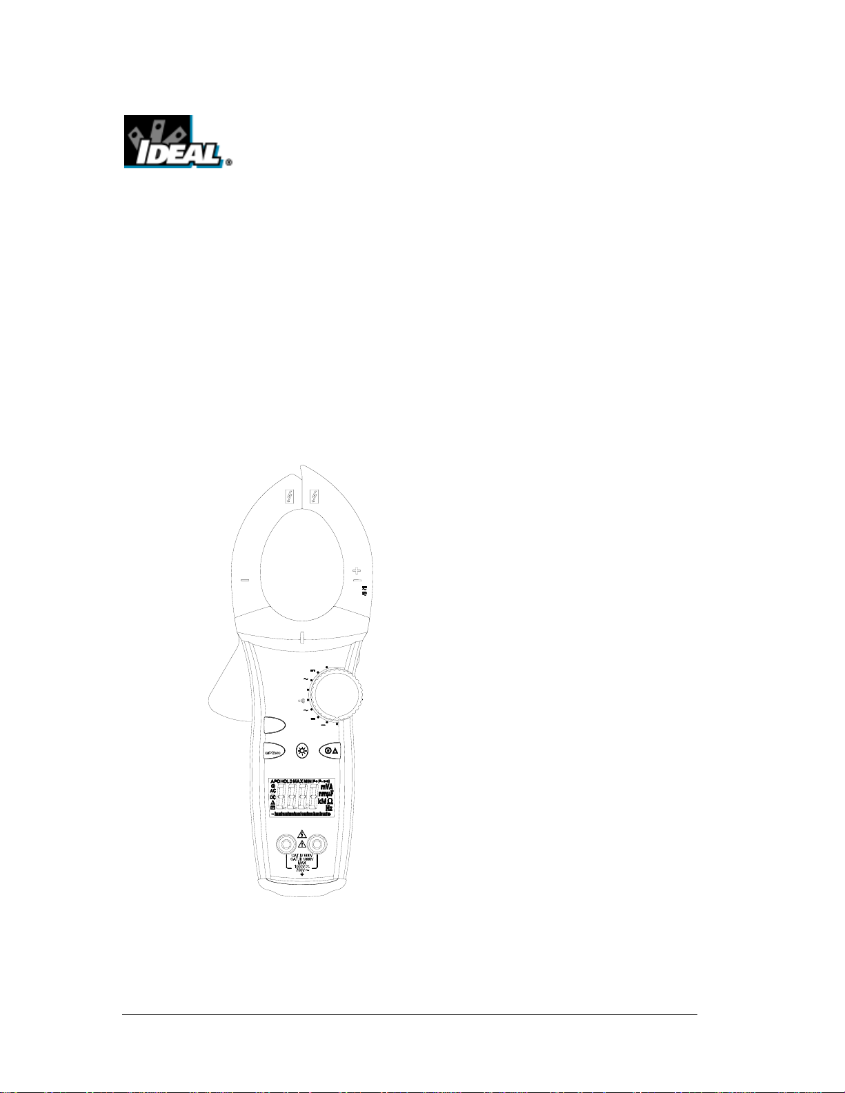
CAT.IV
61-774
MAX
MIN
PEAK
COM
Form number: TM61772-4
Revision: 4. Date: May 2005
HIV
MFD
V
V
Ω
A
400A
1000A
OFF
True RMS
100 203040
V
Ω
600V
1000A
HOLD
Form number TM61772-4 Rev 4 May 2005
Page 2

TABLE OF CONTENTS
Title
Page
Introduction 1
Precautions and Safety Information 1
Symbol Table 1
TightSight™ Display Notes 1
Safety Information 2
Certifications and compliance 2
Specifications 3
General Specification 3
Voltage Specifications 4
Current Specifications 4
Resistance Specifications 4
Capacitance Specifications 4
Continuity Specifications 4
Performance Verification 5/6
Calibration 6/7
Calibration Reference Points 8
Replacing the Battery 9
Form number TM61772-4 Rev 4 May 2005
Page 3
Introduction
Warning
To avoid shock or injury, do not perform the verification
tests or calibration procedures described in this manual
unless you are qualified to do so.
The information provided in this document is for the use
of qualified personnel only.
Caution
The 61-770 series contains parts that can be damaged by static
discharge. Follow the standard practices for handling static sensitive
devices.
For additional information about IDEAL INDUSTRIES, INC. and its products,
and services, visit IDEAL INDUSTRIES, INC. web site at:
www.idealindustries.com
Precautions and Safety Information
Use the meter only as described in the Users Manual. If you do not
do so, the protection provided by the meter may be impaired.
Read the “Safety Information” page before servicing this product.
In this manual, a Warning identifies co nditions and actions that
pose hazard (s) to the user; a Caution identifies conditions and
actions that may damage the meter or the test instruments.
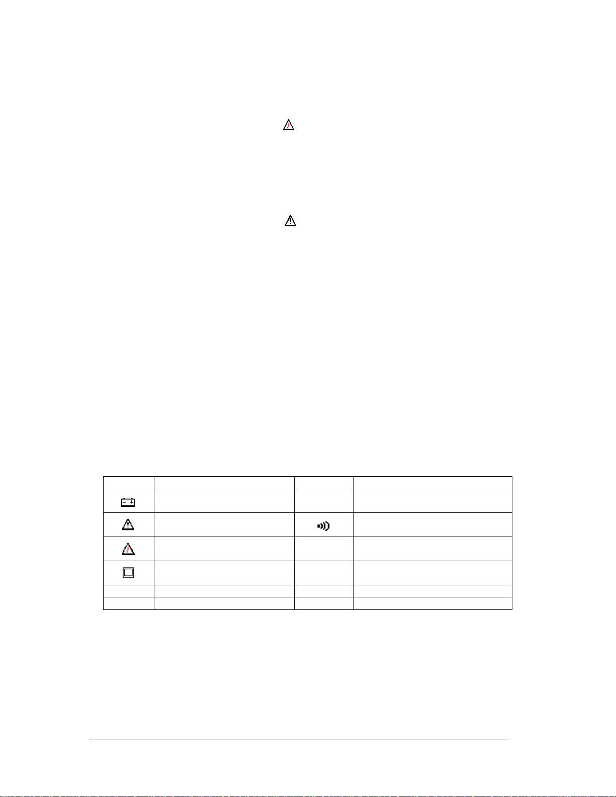
The Symbols
The symbols used on the meter and in this manual are explained
in Table A.
Table A Symbols
Symbol Description Symbol Indicator Lights
CAT III
CAT IV
Battery
Cautionary or important
information in manual
Danger- Risk of electrical
shock
Double Insulation- Protection
Class II
IEC Over-voltage Category III
IEC Over-voltage Category IV
HI-V
High Voltage Indicator
>30 V indicator is on
Continuity indicator
TightSight™ Display Notes:
Only AC/DC amps units of measure are displayed in the TightSight™ display since primary use is
for viewing current measurements in tight locations. The display will show numerical values
only for other functions. The main display is to be used to view units of measure for all other
functions. The backlit of the TightSight™ display functions only in AC or DC current. For all
other measurements, the backlit is disabled.
Page 1
Form number TM61772-4 Rev 4 May 2005
Page 4
Page 2
SAFETY
Review the following safety precautions to avoid injury and prevent damage to this product or any
products connected to it. To avoid potential hazards, use the product only as specified.
CAUTION.
These statements identify conditions or practices that could result in damage to the equipment or other
property.
WARNING.
These statements identify conditions or practices that could result in perso nal injury or loss of life.
Specific precautions
Do not operate without covers. To avoid personal injury, do not apply any voltage or current to the
product without the covers in place.
Electric overload. Never apply a voltage to a connector on the product that is outside the range specified
for that connector.
Avoid electric shock. To avoid injury or loss of life, do not connect or disconnect probes or test leads
while they are connected to a voltage source.
Do not operate in wet/damp conditions. To avoid electric shock, do not operate this product in wet or
damp conditions.
Certifications and compliances
Safety
Designed to EN 61010-1, EN 61010-2-032, UL 61010B-1,
UL 61010B-2-032 specifications
1000V DC Category III
Input rating
600V DC Category IV
750V AC Category III
600V AC Category IV
CAT IV: Outside and service entrance.
CAT III: Distribution level mains, fixed installation.
Over voltage category
CAT II: Local level mains, appliances, and portable equipment.
CAT I: Signal level, special equipment or parts of
equipment, telecommunication, electronics.
Form number TM61772-4 Rev 4 May 2005
Page 5
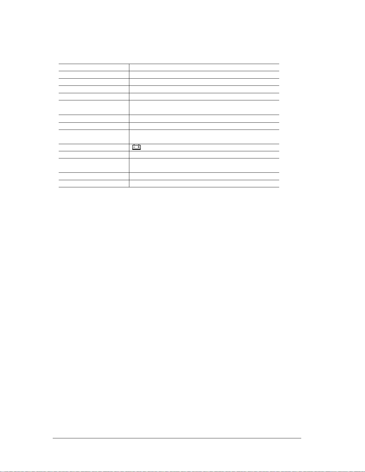
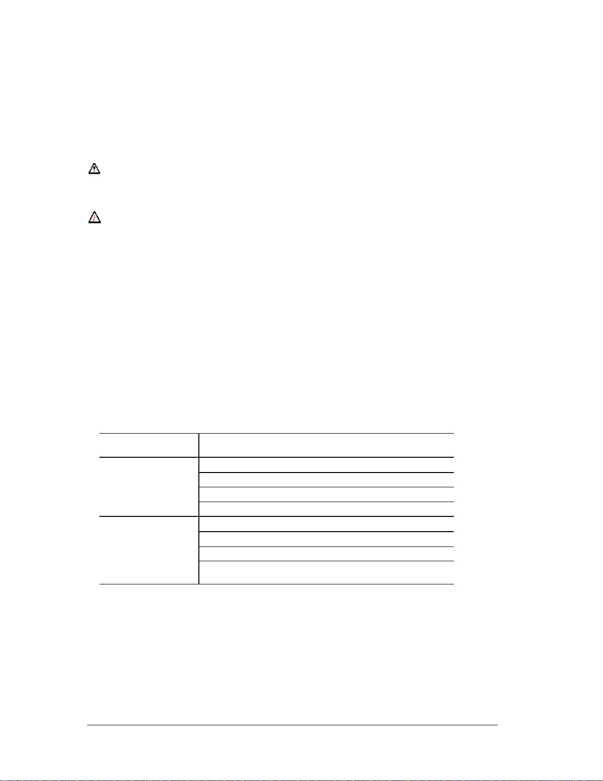
General specifications
Characteristics Description
Display 3¾ Digit LCD display
Display Count 4000 count, maximum reading 3999
Over range Indication “OL” is displayed
Sampling Rate 2.0 time/second
Operating
Relative Humidity
Storage Environment:
0°C to 50°C (32°F to 122°F)
0 ~ 70% RH
-20°C to 60°C (-4°F to 140°F) at <80% relative humidity
Power source: 9V Battery (NEDA 1604)
Battery Live: 200 hours typical (alkaline) {61-772}
150 hours typical (alkaline) {61-774}
Low Battery Indicator: symbol indicates low battery voltage
Auto power off Approximately 30 minutes
Dimensions 10.6” H X 4.1” W X 1.9” D
270mm H X 103mm W X 48.5mm D
Maximum Cable Size ACA 2” (51mm)
Weight: Approximately 17.6 oz. or 500g including battery
RANGES and ACCURACY SPECIFICATION
Accuracy: Accuracy specifications at 23°C ±5°C (73.4°F ±9°F) less than 75% RH.
Temperature Coefficient: 0.1 times the applicable accuracy specification per degree C
from 0°C to 18°C and 28°C to 50°C (32°F to 64°F and 82°F to 122°F)
Electrical Specification: Accuracy are ±(reading plus number of digits) at 23°C ±5°C <75% RH
Page 3
Form number TM61772-4 Rev 4 May 2005
Page 6
Page 4
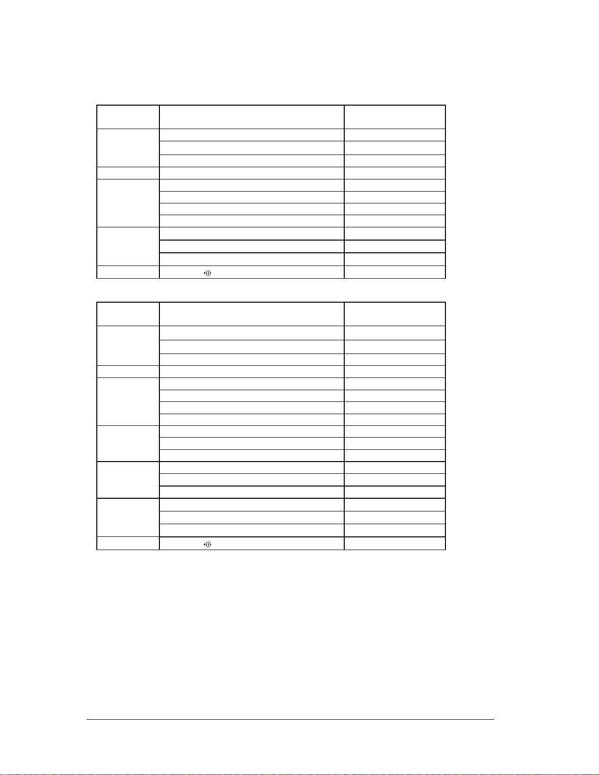
61-772
Function /
Range
AC Voltage
(True RMS)
Ranges Accuracy
400mV, 50Hz - 60Hz 1.2% + 8digits
4V/40V/400V, 50Hz - 500Hz 1.2% + 8 digits
750V, 50Hz - 500Hz 1.5% + 8 digits
DC Voltage 400mV/4V/40V/400V/1000V 0.5% + 2 digits
0A~600A, 50Hz - 60Hz 1.7% + 10 digits
AC Current
(True RMS)
0A~600A, 60Hz - 400Hz 3.0% + 10 digits
600A~1000A, 50Hz – 60Hz 2.5% + 10 digits
600A~1000A, 60Hz – 400Hz 3.5% + 10 digits
1.0% + 4 digits
5.0% + 4 digits
12.0% + 5 digits
Not Specified
Resistance
Continuity
400Ω/4KΩ/40KΩ/400KΩ
4MΩ
40MΩ (>10MΩ not specified)
<35Ω on
Continuity
61-774
Function /
Range
AC Voltage
(True RMS)
Ranges Accuracy
400mV, 50Hz - 60Hz 1.2% + 8 digits
4V/40V/400V, 50Hz - 500Hz 1.2% + 8 digits
750V, 50Hz - 500Hz 1.5% + 8 digits
DC Voltage 400mV/4V/40V/400V/1000V 0.5% + 2 digits
0A~600A, 50Hz - 60Hz 1.7% + 10 digits
AC Current
(True RMS)
0A~600A, 60Hz - 400Hz 3.0% + 10 digits
600A~1000A, 50Hz – 60Hz 2.5% + 10 digits
600A~1000A, 60Hz – 400Hz 3.5% + 10 digits
0A~400A 1.5% + 5 digits
DC Current
400A~800A 2.0% + 5 digits
800A~1000A 3.0% + 5 digits
4µF 3.0% + 10 digits
Capacitance
40µF/400µF 3.0% + 5 digits
4mF 5.0% + 20 digits
1.0% + 4 digits
5.0% + 4 digits
12.0% + 5 digits
Not Specified
Resistance
Continuity
400Ω/4KΩ/40KΩ/400KΩ
4MΩ
40MΩ (>10MΩ not specified)
<35Ω on
Continuity
AC Converter: True RMS Sensing
Overload Protection:
AC and DC Voltage: not to exceed 1000V DC or 750V AC RMS
Resistance: Not to exceed 600V DC or AC RMS
Capacitance, Continuity: not to exceed 600V DC or VAC RMS
Form number TM61772-4 Rev 4 May 2005
Page 7
Page 5
PERFORMANCE VERIFICATIONS
Perform the following analysis; if the meter conforms to the limits listed in Table 1 through 7 the meter is
functioning correctly. If the meter does not conform to any of the listed limits the calibration procedure
must be performed.
Performance Verification Preparation
1. Turn on the calibrator, allow calibrator to warm up. Temperature stabilization should be reached after
30 minutes.
2. Remove battery cover and using a calibrated meter to ensure the battery measures a minimum of 7.5V
DC. If the battery measures under 7.5V DC, replace the battery before beginning the performance test.
3. Input the values listed in Table 1 through 7
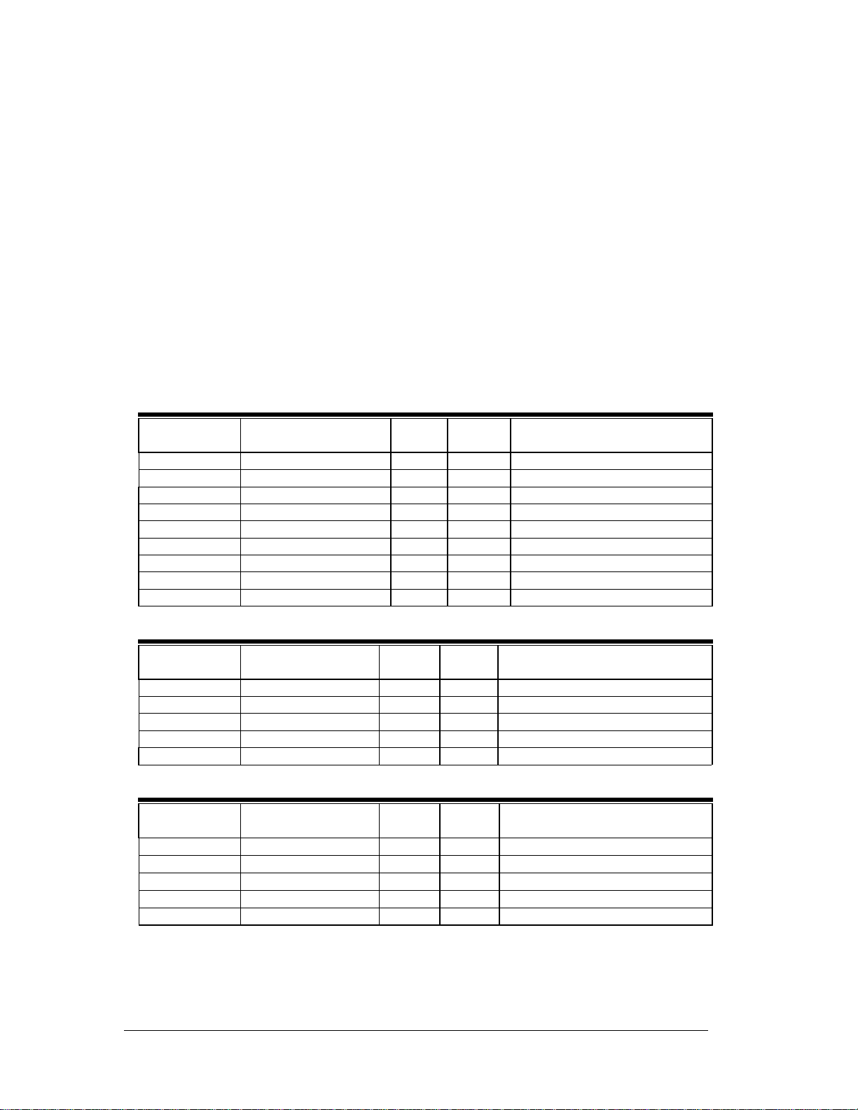
Table 1 AC Voltage Test
Function /Range
Input
Low
Limit
High
Limit
Model number
V AC 400mV 350mV AC @ 50Hz 345.0 355.0 61-772, 61-774
V AC 4V 3.5V AC @ 50Hz 3.450 3.550 61-772, 61-774
V AC 4V 3.5V AC @ 500Hz 3.450 3.550 61-772, 61-774
V AC 40V 35V AC @ 50Hz 34.50 35.50 61-772, 61-774
V AC 40V 35V AC @ 500Hz 34.50 35.50 61-772, 61-774
V AC 400V 350V AC @ 50Hz 345.0 355.0 61-772, 61-774
V AC 400V 350V AC @ 500Hz 345.0 355.0 61-772, 61-774
V AC 750V 700V AC @ 50Hz 681 719 61-772, 61-774
V AC 750V 700V AC @ 500Hz 681 719 61-772, 61-774
Table 2 DC Voltage Test
Function /Range
Input
Low
Limit
High
Limit
Model number
V DC 400mV 350mV 348.0 352.0 61-772, 61-774
V DC 4V 3.5V 3.480 3.520 61-772, 61-774
V DC 40V 35V 34.80 35.20 61-772, 61-774
V DC 400V 350V 348.0 352.0 61-772, 61-774
V DC 1000V 900V 893 907 61-772, 61-774
Table 3 AC Current Test
Function /Range
Input
Low
Limit
High
Limit
Model number
A AC 10A 9.0A AC @ 50Hz 8.74 9.26 61-772, 61-774
A AC 400A 100A AC @ 50Hz 97.3 102.7 61-772, 61-774
A AC 400A 100A AC @ 400Hz 96.0 104.0 61-772, 61-774
A AC 1000A 900A AC @ 50Hz 867 933 61-772, 61-774
A AC 1000A 500A AC @ 400Hz 475 525 61-772, 61-774
Form number TM61772-4 Rev 4 May 2005
Page 8

Page 6
Table 4 DC Current Test
Function /Range
Input
Low
Limit
High
Limit
Model number
A DC 400A 100A DC 98.0 102.0 61-774
A DC 1000A 900A DC 868 932 61-774
Table 5 Resistance Test
Function /Range Input
Ω 400 100Ω
Ω 4K 1KΩ
Ω 40K 10KΩ
Ω 400K 100KΩ
Ω 4M 1MΩ
(1)
Not specified above 10MΩ.
Ω 40M
(1)
10MΩ
Low
Limit
98.6 101.4 61-772, 61-774
.986 1.014 61-772, 61-774
9.86 10.14 61-772, 61-774
98.6 101.4 61-772, 61-774
.946 1.054 61-772, 61-774
8.75 112.5 61-772, 61-774
High
Limit
Model number
Table 6 Capacitance Test
Function /Range
Input
Low
Limit
High
Limit
Model number
MFD 4µF 1µF .960 1.040 61-774
MFD 40µF 10µF 9.65 10.35 61-774
MFD 400µF 100µF 96.5 103.5 61-774
MFD 4mF 1000µF .930 1.070 61-774
Table 7 Diode and Continuity Check
Function /Range
Continuity
Test Value
30Ω beep on,
40Ω beep off
Low
limits
61-772, 61-774
High
Limit
Model number
CALIBRATION
Calibration Preparation
1. Turn on the calibrator, allow calibrator to warm up. Perform calibration at
23±2°C at relative humidity of < 70%. Temperature stabilization should be
reached after 30 minutes.
2. Disconnect the test leads and turn the range switch to “OFF”.
3. Remove the screws holding the battery cover and one at the jaw.
4. Remove the case bottom using care not to damage the battery connector and leads
to the continuity beeper. (Beeper is attached to the bottom case cover.)
5. Using a calibrated meter ensure the battery measures a minimum of 7.5V DC.
If the battery measures under 7.5V DC, replace the battery.
Calibration Procedure
It is recommended that all IDEAL meters undergo the following calibration procedure on
an annual basis.
The class of calibrator or equipment should have an accuracy that exceeds, by an expectable ratio the
accuracy of this instrument.
Form number TM61772-4 Rev 4 May 2005
Page 9

Page 7
V DC Calibration:
61-772 (Refer to Figure 1A), 61-774 (Refer to Figure 2A)
1. Set the function / range to 400mV DC.
2. Connect the calibrator to the V and COM inputs on the meter.
3. Output 390.0mV DC.
Adjust VR1 (VR 1KΩ) until unit display reads 390.0
De-energize source and remove test leads
V AC Zero Calibration:
61-772 (Refer to Figure 1A), 61-774 (Refer to Figure 2A)
1. Set the function /range to 750V AC.
2. Short the V and COM input on the meter.
3. Adjust VR3 (VR 220KΩ) until display reads 000.
De-energize source and remove test leads.
V AC Calibration:
61-772 (Refer to Figure 1A), 61-774 (Refer to Figure 2A)
1. Set the function/range to the 400mV AC.
2. Connect the calibrator to th e V and COM inputs on the meter.
3. Output 390.0mVAC/50Hz.
Adjust VR2 (VR 220KΩ) until unit display reads 390.0 ± 1 digit.
De-energize source and remove test leads.
A AC Calibration:
61-772 (Refer to Figure 1B)
1. Set the function / range to the 400A AC.
2. Set output of the AC calibrator for 10.00A/60Hz +/- 0.01% and connect it to Coil =10N = 100.0A AC
3. Clamp the jaws to the coil = 10N.
4. Adjust VR4 (VR 200Ω) for a display reading of 100.0 ±1 digit.
A DC Zero Calibration
61-774 (Refer to Figure2B)
1. Set the function/range to 400A DC.
2. Short the V and COM inputs on the meter.
3. Adjust VR4 (VR 10KΩ) until display reads 000.
De-energize source and remove test leads.
A DC Calibration
61-774 (Refer to Figure2B)
1. Set the function / range to the 400A DC.
2. Set output of the DC calibrator for +10.00A ± 0.01% and connect it to Coil = 10N = +100.0A DC.
3. Clamp the jaws to the Coil = 10N.
4. Adjust VR5 (VR 2KΩ) for a display reading of 100.0 ±1 digit.
Peak Calibration
If a more accurate “PEAK” measurement is required, then perform the following function.
Depress the “PEAK” button for >2 seconds until “CAL” appears in the display. The meter self-calibrates
to ±3% + 60 digits accuracy. (400m/4VAC/40AAC ranges unspecified)
Calibration of the 61-770 series is complete.
Remove all leads from the calibrator and equipment.
Return unit to proper operating condition.
Form number TM61772-4 Rev 4 May 2005
Page 10

Page 8
61-772 (Figure 1A) 61-772 (Figure 1B)
61-774 (Figure 2A) 61-774 (Figure 2B)
Form number TM61772-4 Rev 4 May 2005
Page 11
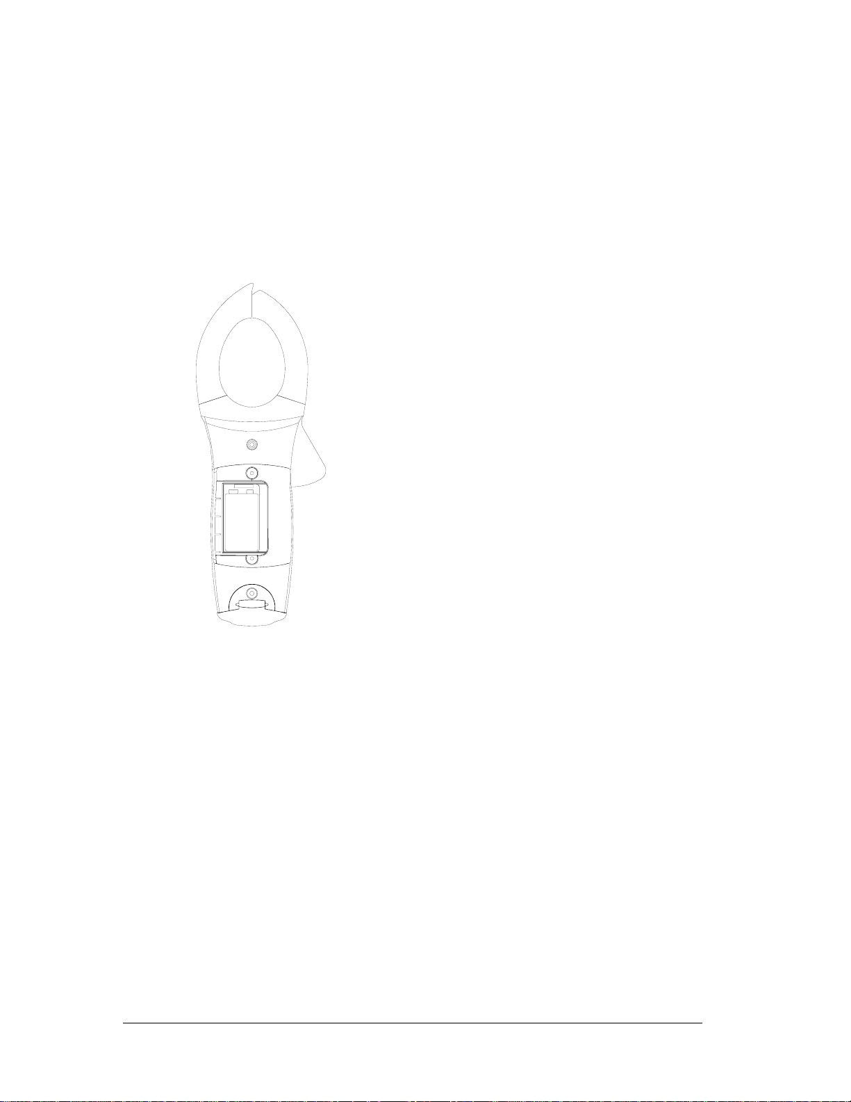
Battery Replacement (refer to Figure 3)
1. Disconnect the test leads from any ci rcuit under t est and t urn off m eter.
2. Use a Philips head screwdriver to remove the screws on battery cover.
3. Remove battery from the battery compartment.
4. Install new 9V battery (NEDA #1604). An alkaline type is recommended.
5. Install new battery into compartment using care to install to proper polarity.
6. Reinstall battery cover.
Page 9
Figure 3
Form number TM61772-4 Rev 4 May 2005
 Loading...