

Page 1
IDEAL INDUSTRIES, INC. TECHNICAL
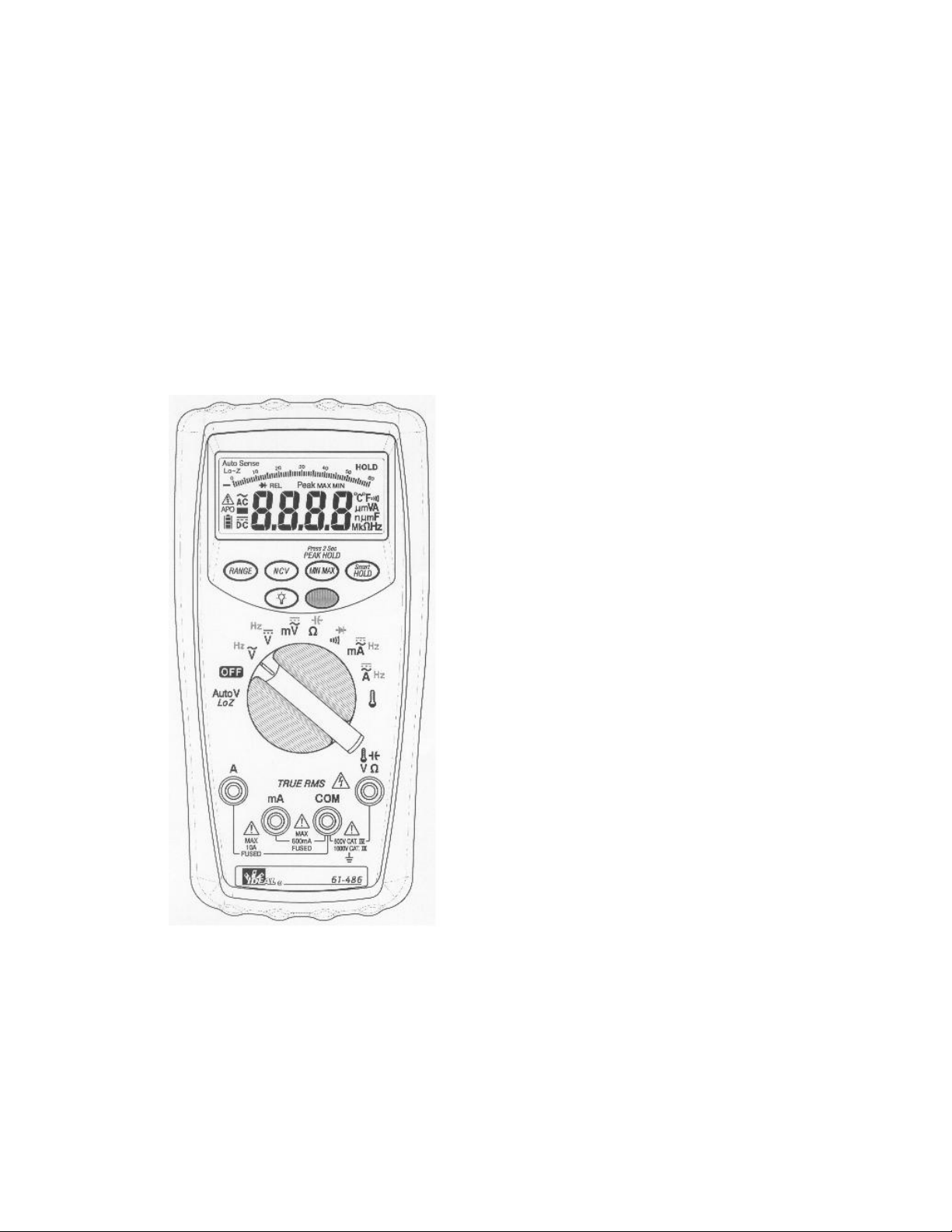
MODEL: 61-484
MODEL: 61-486
Multimeters Service Information
The Service Information provides the following information:
● Precautions and safety information
● Specifications
● Basic maintenance (cleaning, replacing the battery and fuses)
● Performance test procedures
● Calibration and calibration adjustment procedures
Form number: TM61480II
Revision:1. Date: July 2011
Form number TM61480II Rev 1 July 2011
Page 2

Page 1
Table of Contents
Introduction ...................................................................................................................................................... 1
Precautions and Safety Information.................................................................................................................. 1
The Symbols ...................................................................................................................................................... 1
SAFETY ............................................................................................................................................................... 2
SPECIFICATIONS ................................................................................................................................................. 3
General specifications ................................................................................................................................... 3
Measurement Characteristics ....................................................................................................................... 3
Physical and Environmental Characteristics ............................................................................................... 10
Certifications and compliances ................................................................................................................... 10
Required Equipment ....................................................................................................................................... 11
Table B. Required Equipment ..................................................................................................................... 11
Basic Maintenance .......................................................................................................................................... 12
Replacing the Battery .................................................................................................................................. 12
Testing Fuses ............................................................................................................................................... 13
Fuse Replacement ....................................................................................................................................... 13
Performance Tests ........................................................................................................................................... 14
Testing the Voltage Function ....................................................................................................................... 14
Testing the Resistance Function.................................................................................................................. 15
Testing the Capacitance Function ............................................................................................................... 15
Testing the Diode Function ......................................................................................................................... 16
Calibration ....................................................................................................................................................... 19
Environmental Conditions .......................................................................................................................... 19
Activate Calibration Procedure Mode ........................................................................................................ 19
Deactivate Calibration Procedure Mode .................................................................................................... 19
Set Meter Model mode ............................................................................................................................... 19
Standard Function Calibration .................................................................................................................... 19
Temperature Calibration ............................................................................................................................. 19
Calibration Adjustment Point ......................................................................................................................... 20
AC and DC Volts Table ................................................................................................................................. 20
Resistance, Capacitance, Diode, AC & DC Current, Temperature Table ..................................................... 21
Page 3
Page 1
Introduction
Risk of electric shock
See instruction card
DC measurement
Equipment protected by double or enforced insulation
Battery
Fuse
Earth
AC measurement
Conforms to EU directives
Application around and removal from hazardous live
conductors is permitted.
Do not discard this product or throw away
Warning
To avoid shock or injury, do not perform the verification tests or calibration procedures described in the
manual unless you are qualified to do so.
The information provided in this document is for the use of qualified personnel only.
Caution
The 61-484/61-486 contains parts that can be damaged by static discharge. Follow the standard practices
for handling static sensitive devices.
For additional information about IDEAL INDUSTRIES, INC. and its products, and services, visit IDEAL
INDUSTRIES, INC. web site at:
www.idealindustries.com
Precautions and Safety Information
Use the Meter only as described in the Service Manual. If you do not do so, the protection provided by the
Meter may be impaired. Read the “Safety Information” page before servicing this product. In this manual, a
Warning identifies conditions and actions that pose hazard (s) to the user; a Caution identifies conditions and
actions that may damage the Meter or the test instruments.
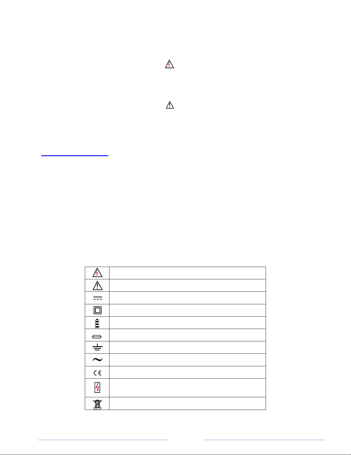
The Symbols
The symbols used on the Meter and in this manual are explained in Table A.
Table A. The Symbols
Page 4

Page 2
SAFETY
Review the following safety precautions to avoid injury and prevent damage to this product or products
connected to it. To avoid potential hazards, use the product only as specified.
CAUTION: These statements identify conditions or practices that could result in damage to the equipment
or other property.
WARNING: These statements identify conditions or practices that could result in personal injury or loss of
life. Specific precautions
Do not operate without covers. To avoid personal injury, do not apply any voltage or current to the product
without covers in place.
Electric overload. Never apply a voltage to a connector on the product that is outside the range specified for
that connector.
Avoid electric shock. To avoid injury or loss of life, do not connect or disconnect probes or test leads while
they are connected to a voltage source.
Do not operate in wet/damp conditions. To avoid electric shock, do not operate this product in wet or damp
conditions.
Page 5
Page 3
Characteristics
Description
Display count
6000
Analog Bar Graph
segment, negative indicated positive implied
Numeric update rate
3 times / sec
Polarity display
Automatic
Over-range display
“OL” is display
Low Battery indicator
indicated full, indicated low
Automatic power-off time
20 minutes
Power source
9V NEDA 1604 IEC 6F22, JIS 006P Battery
Maximum input voltage
600V CAT IV between V and COM
1000V CAT III between V and COM
Maximum floating voltage
600V CAT IV between any terminal and earth ground
1000V CAT III between any terminal and earth ground
V connector
V , V , HZ , , , ,
Temperature Coefficient
0.15×(Spec. Accuracy) / °C, <18°C or >28°C
Battery Life
180 hours typical (9V Alkaline Battery, 1604A)
SPECIFICATIONS
All specifications are warranted unless noted typical and apply to the 61-484/61-486.
Stated accuracies are at 23°C±5°C at than 80% relative humidity and without the battery indicator displayed.
General specifications
Measurement Characteristics
Accuracy is ±(% reading + number of digits) at 23°C ± 5°C, less than 80% R.H. Temperature coefficient: 0.15 *
(Specified accuracy)/℃, < 18℃, > 28℃
Page 6
Page 4
Range
Resolution
61-486 Accuracy
61-484 Accuracy
6.000V
0.001V
±(0.08% reading + 2 digits)
±(0.09% reading + 2 digits)
60.00V
0.01V
600.0V
0.1V
1000V
1V
Range
Resolution
61-486 Accuracy (Sine Wave)
61-484 Accuracy (Sine Wave)
6.000V
0.001V
±(0.8% reading + 3 digits)
±(1.0% reading + 3 digits)
60.00V
0.01V
600.0V
0.1V
1000V
1V
Range
Resolution
61-486 Accuracy
61-484 Accuracy
6.000V
0.001V
±(2% reading + 5 digits)
±(2.5% reading + 5 digits)
60.00V
0.01V
600.0V
0.1V
1000V
1V
(1) DC Voltage
Input Impedance: 10MΩ
Overload Protection: AC/DC 1000V.
(2) AC Voltage
Input Impedance: 10MΩ // less than 100pF
Frequency Response: 50 ~ 1kHz (Sine Wave)
AC Conversion Type: RMS sensing, RMS indication
Additional Accuracy by Crest Factor (C.F.): Add 1.0% for C.F. 1.4 ~ 2.0.
Add 2.5% for C.F. 2.0 ~ 2.5. Add 4.0% for C.F. 2.5 ~ 3.0.
Max. Crest Factor: 1.6 for 6000 ~ 5000 digits
2.0 for 5000 ~ 3000 digits
3.0 for 3000 ~ 0 digits
Overload Protection: AC/DC 1000V.
(3) AC+DC Voltage
Additional specifications are same as voltage function.
The AC+DC True RMS vale might be over selected range since the AC single on DC level. The meter will display
“OL” or change the range while (AC value + DC value) > 6500 counts. Overload Protection: AC/DC 1000V.
Page 7
Page 5
(4) DC mV
Range
Resolution
61-486 Accuracy
61-484 Accuracy
60.00mV
0.01mV
±(0.08% reading + 10 digits)
600.0mV
0.1mV
±(0.08% reading + 2 digits)
±(0.1% reading + 2 digits)
Range
Resolution
61-486 Accuracy (Sine Wave)
61-484 Accuracy (Sine Wave)
60.00mV
0.01mV
±(1.2% reading + 5 digits)
600.0mV
0.1mV
±(1.2% reading + 5 digits)
±(1.5% reading + 5 digits)
Range
Resolution
61-486 Accuracy
61-484 Accuracy
60.00mV
0.01mV
±(2% reading + 10 digits)
600.0mV
0.1mV
±(2% reading + 10 digits)
±(2.5% reading + 5 digits)
Range
Resolution
61-486 Accuracy
61-484 Accuracy
600.0V DC & AC
0.1V
±(0.8% reading + 3 digits)
±(1.0% reading + 3 digits)
1000V DC & AC
1V
±(0.8% reading + 3 digits)
±(1.0% reading + 3 digits)
Input Impedance: 10MΩ
Overload Protection: AC/DC 1000V.
(5) AC mV
Input Impedance: 10MΩ // less than 100pF
Frequency Response: 50 ~ 1k Hz (Sine Wave)
AC Conversion Type: RMS sensing, RMS indication Additional Accuracy by Crest Factor (C.F.): Same as ACV.
Max. Crest Factor: Same as ACV.
Overload Protection: AC/DC 1000V.
(6) AC+DC mV
Additional specifications are same as mV function.
The AC+DC True RMS vale might be over selected range since the AC single on DC level. The meter will display
“OL” or change the range while (AC value + DC value) > 6500 counts. Overload Protection: AC/DC 1000V.
(7) Lo-Z Voltage (Auto DC & AC Detection)
Input Impedance: less than 6kΩ
AC Frequency Response: 50 ~ 1kHz (Sine Wave) AC Conversion Type: RMS sensing, RMS indication Additional
Accuracy by Crest Factor (C.F.): Same as ACV. Max. Crest Factor: Same as ACV.
Overload Protection: AC/DC 1000V.
Page 8

Page 6
Range
Resolution
61-486 Accuracy
61-484 Accuracy
6.000A
0.001A
±(0.8% reading + 3 digits)
±(1.0% reading + 3 digits)
10.00A
0.01A
Range
Resolution
61-486 Accuracy (Sine Wave)
61-484 Accuracy (Sine Wave)
6.000A*
0.001A
±(1.2% reading + 3 digits)
±(1.5% reading + 3 digits)
10.00A
0.01A
Range
Resolution
61-486 Accuracy
61-484 Accuracy
6.000A
0.001A
±(2% reading + 5 digits)
±(2.5% reading + 5 digits)
10.00A
0.01A
Range
Resolution
61-486 Accuracy
61-484 Accuracy
60.00mA
0.01mA
±(0.8% reading + 3 digits)
±(1.0% reading + 3 digits)
600.0mA
0.1mA
(8) DC Current
Maximum measurement time: 3 minutes at 10A with at least 20 minutes rest time.
Overload Protection: AC/DC 11A.
(9) AC Current
Frequency Response: 50 ~ 1kHz (Sine Wave)
AC Conversion Type: RMS sensing, RMS indication Additional Accuracy by Crest Factor (C.F.): Same as ACV.
Max. Crest Factor: Same as ACV.
Maximum measurement time: 3 minutes at 10A with at least 20 minutes rest time.
Overload Protection: AC/DC 11A.
(10) AC+DC Current
Additional specifications are same as Ampere function.
The AC+DC True RMS vale might be over selected range since the AC single on DC level. The meter will display
“OL” or change the range while (AC value + DC value) > 6500 counts. Overload Protection: AC/DC 11A.
(11) DC mA
Maximum measurement time: 10 minutes at 600mA with at least 20 minutes rest time.
Overload Protection: AC/DC 440mA.
Page 9

Page 7
Range
Resolution
61-486 Accuracy (Sine Wave)
61-484 Accuracy (Sine Wave)
60.00mA
0.01mA
±(1.2% reading + 3 digits)
±(1.5% reading + 3 digits)
600.0mA
0.1mA
Range
Resolution
61-486 Accuracy
61-484 Accuracy
60.00mA
0.01mA
±(2% reading + 5 digits)
±(2.5% reading + 5 digits)
600.0mA
0.1mA
Range
Resolution
Accuracy
600.0Ω
0.1Ω
±(0.8% reading + 5 digits)
6.000kΩ
0.001kΩ
±(0.8% reading + 2 digits)
60.00kΩ
0.01kΩ
600.0kΩ
0.1kΩ
6.000MΩ
0.001MΩ
40.00MΩ *
0.01MΩ
±(1.0% reading + 5 digits)
Range
Resolution
Accuracy
600.0Ω
0.1Ω
±(0.8% reading + 5 digits)
(12) AC mA
Frequency Response: 50 ~ 1kHz (Sine Wave)
AC Conversion Type: RMS sensing, RMS indication Additional Accuracy by Crest Factor (C.F.): Same as ACV.
Max. Crest Factor: Same as ACV.
Maximum measurement time: 10 minutes at 600mA with at least 20 minutes rest time.
Overload Protection: AC/DC 440mA.
(13) AC+DC mA
Additional specifications are same as mA function.
The AC+DC True RMS vale might be over selected range since the AC single on DC level. The meter will display
“OL” or change the range while (AC value + DC value) > 6500 counts. Overload Protection: AC/DC 440mA.
(14) Resistance
* There is a little rolling less then ±50 digits when measuring > 10.00 MΩ.
Open Circuit Voltage: Approx. 2.5V for 600.0Ω & 6.000kΩ range.
Approx. 0.6V for others Maximum Test Current: Approx. 0.1mA. Overload Protection: AC/DC 1000V.
(15) Continuity
Page 10

Page 8
Range
Resolution
Accuracy
2.000V
0.001V
±(1.5% reading + 2 digits)
Range
Resolution
Accuracy
1.000µF
0.001µF
±(1.2% reading + 2 digits)
10.00µF
0.01µF
100.0µF
0.1µF
1.000mF
0.001mF
10.00mF
0.01mF
Range
Resolution
Accuracy
100.00Hz
0.01Hz
±(0.1% reading + 2 digits)
1000.0Hz
0.1Hz
10.000kHz
0.001kHz
100.00kHz
0.01kHz
Open Circuit Voltage: Approx. 2.5V
Continuity: Built-in buzzer sounds when measured resistance is less than 30Ω and sounds off when measured
resistance is more than 100Ω, Between 30Ω to 100Ω the buzzer maybe sound or off either.
Continuity Indicator: 2.7KHz Tone Buzzer Response Time of Buzzer: < 500 μsec. Overload Protection: AC/DC
1000V.
(16) Diode
Open Circuit Voltage: Approx. 2.5V Maximum Test Current: Approx. 0.4mA. Overload Protection: AC/DC
1000V.
(17) Capacitance
Response Time: < 0.7 sec. for 1nF ~ 1mF
< 3 sec. for 1mF ~ 10mF
Overload Protection: AC/DC 1000V
(18) Frequency
Maximum Sensitivity: 1000V rms or 600mA rms or 10A rms
Minimum Sensitivity: > 5.0Vp-p (for ACV 1Hz ~ 10kHz)
> 10.0Vp-p (for ACV 10kHz ~ 100kHz)
> 2mAp-p (for AC mA)
> 0.2Ap-p (for ACA)
Overload Protection: AC/DC 1000V or 11A
Page 11

Page 9
Range
Resolution
Accuracy
-40.0℃ ~ 400.0℃
0.1℃
±(1% reading + 10 digits)
-40.0℉
~ 752.0℉
0.1℉
±(1% reading + 18 digits)
(19) Temperature (61-486 Only)
Does not include accuracy of the thermocouple probe.
Accuracy specification assumes surrounding temperature stable to ±1 ℃. For surrounding
temperature changes of ±5 ℃, rated accuracy applies after 2 hours.
Overload Protection: AC/DC 1000V.
(20) Peak Hold (61-486 Only, for Voltage & Ampere Function)
Specified accuracy ± 150 digits.
(21) Thermocouple (61-486 Only)
K Type Class II Thermocouple with standard dual banana jack. Measurement Range: -40.0℃ ~
200.0℃
(-40.0℉
~ 392.0℉) Accuracy: ±2.0℃
(22) Over-range Indication
Display “OL” or “-OL
(23) Auto Power Off
The meter automatically turns the power off after powering up and no operation for 20 ± 5 minutes.
To power up, press any button or dial the rotary switch.
(24) Measuring Rate:
Approximate 3 times/sec.
(25) Fuse:
11A/600V Fast Action Fuse for A Terminal.
440mA/1000V Fast Action Fuse for mA Terminal.
(26) Battery:
9V Battery
(27) Low Battery
Voltage: 7.0V ± 0.1V
(28) Battery life (ALKALINE):
Approx. 26 hours with backlight on. Approx. 180 hours with backlight off.
(29) Overvoltage Category
IEC 61010-1 CAT. III 1000V, CAT. IV 600V
Page 12

Page 10
Characteristics
Description
Dimensions (H×W×D)
48mm×94mm×190mm (with holster)
Weight (with battery)
460g (with battery)
Environmental characteristics
Description
Temperature operating
-10 to +50°C
Non-Operating
-20 to +60°C
Humidity (operating)
<80% R.H.
Altitude Operating
2,000M (6560 ft.)
Non-Operating
12,300M (40354 ft.)
Vibration & shock Operating
Random Vibration per MIL-PRF-28800F Class 2
Indoor Use
Indoor Use
Safety
IEC 61010-1 600V CAT IV
Input rating
V / Ω: Category III 1000 Volts
V / Ω: Category IV 600 Volts
Over voltage category
CAT I : The source of the Low-Voltage installation.
CAT II: The building installation.
CAT III: The circuits directly connected to Low-Voltage installation.
CAT IV: The circuits not connected to mains.
Pollution Degree 2
Do not operate in environments where conductive
Pollutants may be present.
(30) Operating Temperature
-10℃ ~ 30℃,
30℃ ~ 40℃, ≦75%RH
40℃ ~ 50℃, ≦45%RH
≦
80%RH
(31) Storage Temperature
-20℃ ~ +60℃, 0 ~ 80%RH (No batteries)
Physical and Environmental Characteristics
Certifications and compliances
Page 13

Page 11
EC Declaration of Conformity
Meets the intent of Directive 2004/108/EEC for Electromagnetic
Compatibility and Low Voltage Directive 2006/95/EEC for
specifications as listed in the official Journal of the European
Communities:
EN 61326
IEC/EN 61010
Equipment
Required Characteristics
Recommended Model
Calibrator
AC Voltage:
Range: 0 ~ 1000V AC
Accuracy: +/- 0.07%
Frequency Range: 40 ~ 100kHz
Accuracy: +/- 0.01%
DC Voltage
Range: 0 ~ 1000V DC
Accuracy: +/- 0.006%
AC Ampere
Range: 0 ~ 10A AC
AC mA Accuracy: +/- 0.15% AC A Accuracy: +/- 0.21%
Frequency Range: 40 ~ 30kHz Accuracy: +/- 0.01%
DC Ampere
Range: 0 ~ 10A DC
DC mA Accuracy: +/- 0.0175%
DC A Accuracy: +/- 0.08%
Frequency Source
Range: 0.1Hz ~ 4MHz
Accuracy: +/- 0.003%
Resistance
Range: 0Ω ~ 40MΩ
Accuracy: +/- 0.02%
Capacitance
Range: 1nF ~ 10mF
Accuracy: +/- 0.5%
Temperature
Range: 0 ~ 1200 °C
Accuracy: +/- 0.2%
Fluke 5500 or Wavetek
9100 Calibrator or
equipment
Required Equipment
Required equipment is listed in Table B. If the recommended models are not available, equipment with
equivalent specifications may be used.
Repairs or servicing should be performed only by qualified personnel.
Table B. Required Equipment
Page 14

Page 12
Basic Maintenance
Warning
To avoid shock, remove the test leads and any input signals before opening the case or replacing the battery.
Opening the Meter Case
Caution
To avoid unintentional shock circuit, always place the uncovered Meter assembly on a protective surface.
When the case of the Meter is open, circuit connections are exposed.
To open the Meter case, do the following:
Replacing the Battery
Low battery indication
The Meter powered by 9V battery.
To replace the battery refer to figure.
1. Disconnect test leads from any live source, switch off the meter.
2. Remove the back case by using a flat-blade screwdriver to turn the screws counter-clockwise.
Page 15

Page 13
Testing Fuses
To test the internal fuses of the meter.
1. Turn the rotary switch to the Ω position.
2. To test FUSE 71 (Bussmann DMM-B-11A recommended), plug a test lead into VΩHz input terminal,
and use the probe to touch the A input terminal. The display should indicate between 0.0 to 0.3Ω.
3. To test FUSE 72 (Bussmann DMM-B-44/100 recommended), plug a test lead into VΩHz input
terminal, and use the probe to touch the mA input terminal. The display should indicate between 0.0
to 2.5Ω.
4. If display reading is higher than the range, replace the fuse.
Fuse Replacement
Refer to the following figure to replace fuse:
Page 16

Page 14
Performance Tests
Step
Input
Frequency
Reading
1
5.000V AC
50Hz
4.957V ~ 5.043V
2
5.000V AC
1000Hz
4.957V ~ 5.043V
3
50.00V AC
50Hz
49.57V ~ 50.43V
4
50.00V AC
1000Hz
49.57V ~ 50.43V
5
500.0V AC
50Hz
495.7V ~ 504.3V
6
500.0V AC
1000Hz
495.7V ~ 504.3V
7
900.0V AC
50Hz
890V ~ 910V
8
900.0V AC
1000Hz
890V ~ 910V
9
5.000V DC
4.994V ~ 5.006V
10
50.00V DC
49.94V ~ 50.06V
11
500.0V DC
499.4V ~ 500.6V
12
900V DC
897V ~ 903V
13
50.00mV AC
50Hz
49.35mV ~ 50.65mV
The following performance tests verify the complete operability of the Meter and check the accuracy of each
Meter function against the Meter’s specifications.
Accuracy specifications are valid for a period of one year after calibration, when measured at an operating
temperature of 18°C to 28°C and a maximum of 80% relative humidity.
To perform the following tests, it is not necessary to open the case, no adjustments are necessary, merely
make the required connections, apply the designated inputs, determine if the reading on the Meter display
falls within the acceptable range indicated.
If the Meter fails any of these tests, it needs calibration adjustment or repair.
Testing the Voltage Function
To verify accuracy in the AC and DC voltage ranges, do the following:
1. Turn on the meter, and turn the rotary switch to the correct position.
2. Connect the Calibrator to the VΩ and COM inputs on the Meter.
3. Set the Calibrator for the voltage and frequency from step 1 to 20 in Table 1.
4. Compare the reading on the Meter display with the reading shown in Table 1.
5. If the display reading falls outside of the range shown in Table 1, the Meter does not meet
specification.
Table 1 Voltage Test:
Page 17

Page 15
Step
Input
Frequency
Reading
14
50.00mV AC
1000Hz
49.35mV ~ 50.65mV
15
500.0mV AC
50Hz
493.5mV ~ 506.5mV
16
500.0mV AC
1000Hz
493.5mV ~ 506.5mV
17
50.00mV DC
49.86mV ~ 50.14mV
20
500.0mV DC
499.4mV ~ 500.6mV
Step
Input
Reading
1
500.0Ω
495.5Ω ~ 504.5Ω
2
5.000KΩ
4.958KΩ ~ 5.042KΩ
3
50.00KΩ
49.58KΩ ~ 50.42KΩ
4
500.0KΩ
495.8KΩ ~ 504.2KΩ
5
5.000MΩ
4.958MΩ ~ 5.042MΩ
6
36.00MΩ
35.59MΩ ~ 36.41MΩ
Testing the Resistance Function
To verify accuracy in the resistance function, do the following:
1. Turn on the meter, and turn the rotary switch to Ω position.
2. Connect the Calibrator to the VΩ and COM inputs on the Meter.
3. Set the Calibrator for the voltage and frequency from step 1 to 6 in Table 2.
4. Compare the reading on the Meter display with the reading shown in Table 2.
5. If the display reading falls outside of the range shown in Table 2, the Meter does not meet
specification.
Table 2 Resistance Test:
Testing the Capacitance Function
To verify accuracy in the AC and DC capacitance function, do the following:
1. Turn on the meter, and turn the rotary switch to the capacitance position.
2. Connect the Calibrator to the VΩ and COM inputs on the Meter.
3. Set the Calibrator for the voltage and frequency from step 1 to 5 in Table 3.
4. Compare the reading on the Meter display with the reading shown in Table 3.
5. If the display reading falls outside of the range shown in Table 3, the Meter does not meet
specification.
Page 18

Page 16
Step
Input
Reading
1
0.900µF
0.887µF ~ 0.913µF
2
9.00µF
8.87µF ~ 9.13µF
3
90.0µF
88.7µF ~ 91.3µF
4
0.900mF
0.887mF ~ 0.913mF
5
9.00mF
8.87mF ~ 9.13mF
Step
Input
Reading
1
1.800V
1.771V ~ 1.829V
2
Silicon Diode
0.450V ~ 0.650V
Table 3 Capacitance Test:
Testing the Diode Function
To verify accuracy in the AC and DC capacitance function, do the following:
1. Turn on the meter, and turn the rotary switch to µF position.
2. Connect the Calibrator to the VΩ and COM inputs on the Meter.
3. Set the Calibrator for the voltage from step 1 in Table 4.
4. Compare the reading on the Meter display with the display reading shown in Table 4.
5. Connect a silicon diode to the VΩ and COM inputs on the Meter.
6. Compare the reading on the Meter display with the display reading shown in Table 4.
7. If the display reading falls outside of the range shown in Table 4, the Meter does not meet
specification.
Table 4 Diode Test:
Testing the mA Function
To verify accuracy in the AC and DC mA ranges, do the following:
1. Turn on the meter, and turn the rotary switch to the correct position.
2. Connect the Calibrator to the mA and COM inputs on the Meter.
3. Set the Calibrator for the voltage and frequency from step 1 to 6 in Table 5.
4. Compare the reading on the Meter display with the reading shown in Table 5.
5. If the display reading falls outside of the range shown in Table 5, the Meter does not meet
specification.
Page 19

Page 17
Step
Input
Frequency
Reading
1
50.00mA AC
50Hz
49.37mA ~ 50.63mA
2
50.00mA AC
1000Hz
49.37mA ~ 50.63mA
3
500.0mA AC
50Hz
493.7mA ~ 506.3mA
4
500.0mA AC
1000Hz
493.7mA ~ 506.3mA
5
50.00mA DC
49.57mA ~ 50.43mA
6
500.0mA DC
495.7mA ~ 504.3mA
Step
Input
Frequency
Reading
1
5.000A AC
50Hz
4.937A ~ 5.063A
2
5.000A AC
1000Hz
4.937A ~ 5.063A
3
9.00A AC
50Hz
8.86A ~ 9.14A
4
9.00A AC
1000Hz
8.86A ~ 9.14A
5
5.000A DC
4.957A ~ 5.043A
6
9.00A DC
8.90A ~ 9.10A
Table 5 mA Test:
Testing the Ampere Function
To verify accuracy in the AC and DC ampere ranges, do the following:
1. Turn on the meter, and turn the rotary switch to the correct position.
2. Connect the Calibrator to the A and COM inputs on the Meter.
3. Set the Calibrator for the voltage and frequency from step 1 to 20 in Table 6.
4. Compare the reading on the Meter display with the reading shown in Table 6.
5. If the display reading falls outside of the range shown in Table 6, the Meter does not meet
specification.
6. Table 6 Ampere Test:
Testing the Temperature Function
To verify accuracy in the temperature function, do the following:
1. Turn on the meter, and turn the rotary switch to the temperature position.
2. Connect the Calibrator to the VΩ and COM inputs on the Meter.
3. Set the Calibrator for the temperature from step 1 to 5 in Table 7.
4. Compare the reading on the Meter display with the reading shown in Table 7.
5. If the display reading falls outside of the range shown in Table 7, the Meter does not meet
specification.
Page 20

Page 18
Step
Input
Reading
1
-40.0°F
-37.8°F ~ -42.2°F
2
0.0°F
-1.8°F ~ 1.8°F
3
32.0°F
29.9°F ~ 34.1°F
4
350.0°F
344.7°F ~ 355.3°F
5
700.0°F
691.2°F ~708.8°F
Table 7 Temperature Test:
Page 21

Page 19
Calibration
Environmental Conditions
Perform calibration at an ambient temperature and relative humidity (23°C±2°C and R.H.≦80%). Allow the
instrument to sit at this temperature for at least 30 minutes.
The Operation of Calibration Procedure Mode
Activate Calibration Procedure Mode
Press “Hold” button while powering up, then press buttons in the following sequence to activate the
calibration procedure mode
Range → Backlight → VoltSense → Hold → Blue → Min Max
. (The “Auto” segment will flash while you are in calibration mode. )
Deactivate Calibration Procedure Mode
Turn the meter off to deactivate calibration procedure mode.
Set Meter Model mode (61-484 and 61-486 61-486 / 61-484)
After Activate Calibration Procedure Mode, Press the “Min Max” button to select the meter model.
Standard Function Calibration (Voltage, Ampere, Resistance, Diode, Capacitance)
Dial the rotary switch and press the “Blue” button to select the measurement mode.
Press the “Range” button to select the range which will be calibrated.
Apply the standard signal indicated in the Calibration Adjustment Point Table to the suitable input
terminals.
Once LCD display to stable, Press the “Hold” button to confirm the reading.
If the reading is not within a 10% tolerance of the correct reading when pressing the “Hold” button,
the LCD will display “Err”. Press “Hold” button to exit. Meter will need to be returned for repair.
Temperature Calibration
Connect the temperature calibrator to the meter and wait for at 30 minutes
Apply the standard voltage indicated in the Calibration Adjustment Point Table to the input
terminals.
Once the LCD display is stable, Press the “Hold” button to confirm reading.
If the reading is not within a 10% tolerance of the correct reading when pressing the “Hold” button,
the LCD will display “Err”. Press “Hold” button to exit. Meter will need to be returned for repair.
Page 22

Page 20
Function
Range
Standard Value
61-486
61-484
DC mV
60.00mV
30.00mV
O 55.00mV
O
600.0mV
300.0mV
O O 550.0mV
O
O
DCV
6.000V
3.000V
O O 5.500V
O
O
60.00V
30.00V
O O 55.00V
O
O
600.0V
300.0V
O O 550.0V
O O 1000V
950V
O
O
AC mV
60.00mV
2.00mV, 50Hz
O 10.00mV, 50Hz
O 55.00mV, 50Hz
O
600.0mV
20.0mV, 50Hz
O O 100.0mV, 50Hz
O O 550.0mV, 50Hz
O
O
ACV
6.000V
0.200V, 60Hz
O O 1.000V, 60Hz
O O 5.000V, 60Hz
O
O
60.00V
2.00V, 60Hz
O O 10.00V, 60Hz
O O 50.00V, 60Hz
O
O
600.0V
20.0V, 60Hz
O O 100.0V, 60Hz
O O 500.0V, 60Hz
O
O
1000V
200V, 60Hz
O O 500V, 60Hz
O O 950V, 60Hz
O
O
Calibration Adjustment Point
AC and DC Volts Table
Page 23

Page 21
Resistance, Capacitance, Diode, AC & DC Current, Temperature Table
Function
Range
Standard Value
61-486
61-484
Resistor
600.0Ω
500.0Ω
O O 6.000kΩ
5.000kΩ
O O 60.00kΩ
50.00kΩ
O O 600.0kΩ
500.0kΩ
O O 6.000MΩ
5.000MΩ
O O 40.00MΩ
38.00MΩ
O
O
Capacitor
1.000μF
0.370μF
O O 10.00μF
3.70μF
O O 100.0μF
37.0μF
O O 1.000mF
0.360mF
O O 10.00mF
3.60mF
O O Diode
2.000V
1.800V
O
O
DC mA
60.00mA
30.00mA
O
O
55.00mA
O
O
600.0mA
300.0mA
O O 450.0mA
O
O
AC mA
60.00mA
2.00mA, 60Hz
O O 10.00mA, 60Hz
O O 50.00mA, 60Hz
O
O
600.0mA
20.0mA, 60Hz
O O 100.0mA, 60Hz
O O 500.0mA, 60Hz
O
O
DCA
6.000A
3.000A
O O 5.500A
O O 10.00A
9.500A
O
O
ACA
6.000A
0.200A, 500Hz
O O 1.000A, 500Hz
O O 5.000A, 500Hz
O
O
10.00A
2.00A, 60Hz
O O 5.00A, 60Hz
O
O
9.50A, 60Hz
O
O
Temperature
752.0°F
12.209mV
O
32.0°F
O
 Loading...