

Page 1

1
350 Series
Digital Multimeter
#61-350
#61-352
#61-354(TRMS)
Page 2

2
Features
Auto / Manual Ranging
Non-Contact Voltage (NCV) 80-600V AC
Measures AC/DC Current (352 and 354 only)
Measures AC/DC Voltage and Resistance
Measures Frequency and Capacitance (352 and
354 only)
Audible Continuity
Data Hold
Low Battery Indication
Auto Power Off
Large Numbers and Symbols
Electronic overload protection on all ranges
Warning
. . . . . . . . . .
. . . . . . . . . .
. . . . . . . . . .
. . . . . . . .
Safety sheet
. . . . . . . . .
. . . . . . . . . .
. . . . . . . . . .
. . . . . . . .
. . . . . . . . .
2 Read First
2 Safety Information
Understand and follow operating instructions
carefully. Use the meter only as specified in this
manual; otherwise, the protection provided by
the meter may be impaired.
WARNING
To avoid possible electric shock, personal injury
or death, follow these instructions:
․ Do not use if meter appears damaged, Visually
inspect the meter to ensure case is not
cracked and back case is securely in place.
․ Inspect and replace leads if insulation is
damaged,metal is exposed or probes are
cracked. Pay particular attention to the
insulation surrounding the connectors.
․ Do not use Meter if it operates abnormally as
protection maybe impaired.
․ Do not use during electrical storms or in wet
weather.
․ Do not use around explosive gas, dust or
vapor.
․ Do not apply more than the rated voltage to
the meter.
․ Do not use without the battery and the back
case properly installed.
Page 3

3
․ Remove the test leads from the circuit prior to
removing battery cap.
․ Do not attempt to repair this unit as it has no
userserviceable parts.
․ Voltages exceeding 30VAC or 60VDC pose a
shock hazard so use caution.
CAUTION
To protect yourself, think “Safety First”:
․ Use appropriate personal protective equipment
such as safety glasses, face shields, insulating
gloves, insulating boots and/or insulating mats.
․ Before each use.
- Perform a continuity test by touching the test
leads together to verify the functionally of the
battery and test leads.
- Use the 3 Point Safety Method. (1) Verify
meter operation by measuring a known
voltage. (2) Apply meter to circuit under test.
(3) Return to the known live voltage again to
ensure proper operation.
․ Never ground yourself when taking electrical
measurements.
․ Connect the black common lead to ground or
neutral before applying the red test lead to
potential voltage. Disconnect the red test lead
from the voltage first.
․ Always work with a partner.
․ When using the probes, keep fingers as far
behind the probe tips as possible.
․ Never connect a source of voltage with the
function rotary switch in Ω/ :</ A //Hz
position.Never set the meter in A function
to measure the voltage of a power supply
circuit in equipment that could result in
damage to the meter and the equipment
under test.
Page 4
4
Risk of electric shock
See instruction card
DC measurement
Equipment protected by double or
reinforced insulation
Battery
Fuse
Earth
AC measurement
Conforms to EU directives
Symbols as marked on the meter and
Instruction card
Page 5
5
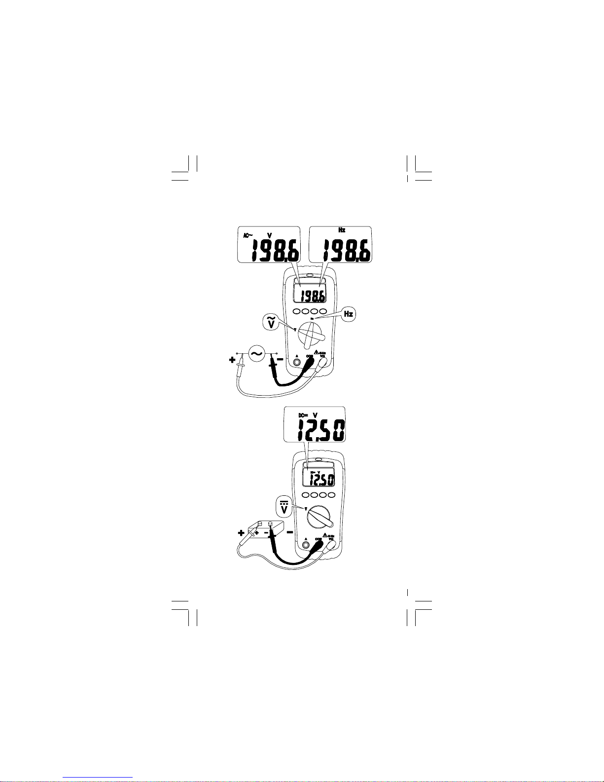
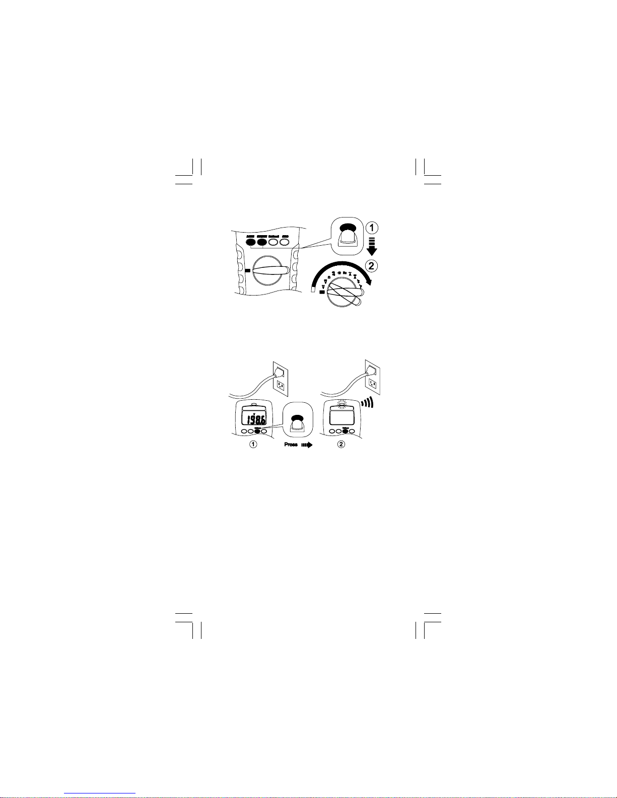
Measuring AC/DC Voltage And
Frequency
Page 6

6
Resistance
/630V 1 F
Capacitor
Discharge hight-voltage
Circuit
Power off
Disconnect
Testing for Continuity
Page 7
7
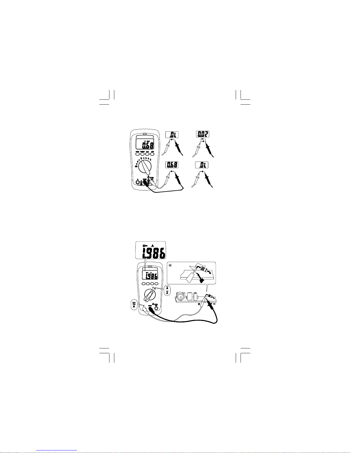
Measuring DC / AC Current
(For 352,354 only)
Disconnect
Testing for Diode
Black
Red
Red
Black
Good Diode
Bad Diode
Red
Black
Red
Black
Page 8
8
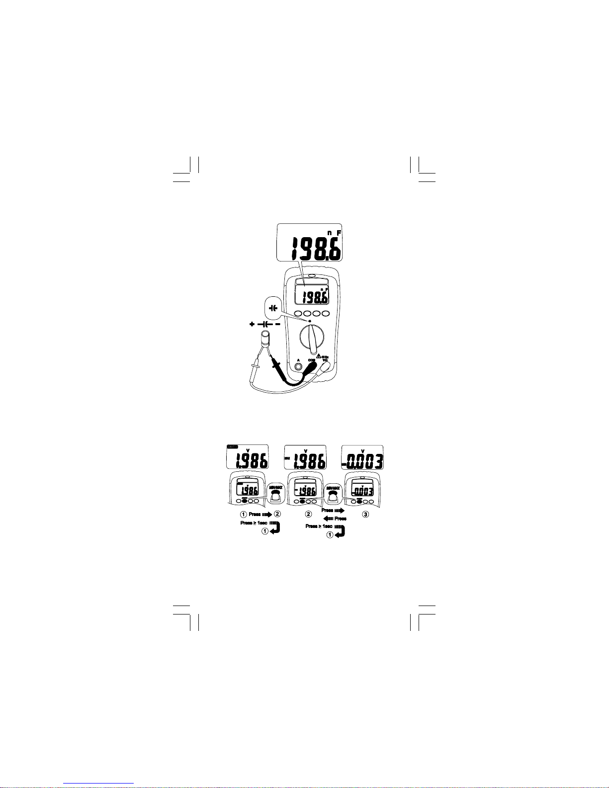
MIN MAX Re c o r d
Measuring Capacitance
(For 352,354 only)
Page 9

9
Display Hold
Auto Power Off (Battery Saver)
10 min
Manual Ranging and Auto Ranging
Page 10
10
Disable Auto Power Off
NCV
1. NCV switch will be activated on any function
or at OFF status.
2. Test leads are not used for the NCV test.
3. Press the NCV button. The display goes
black, a tone sounds and the red LED lights
up to verify the instrument is operational.
The NCV button must be held down to detect
the presence of voltage without use of the
leads.
Non-Contact Voltage (NCV)
Page 11
11
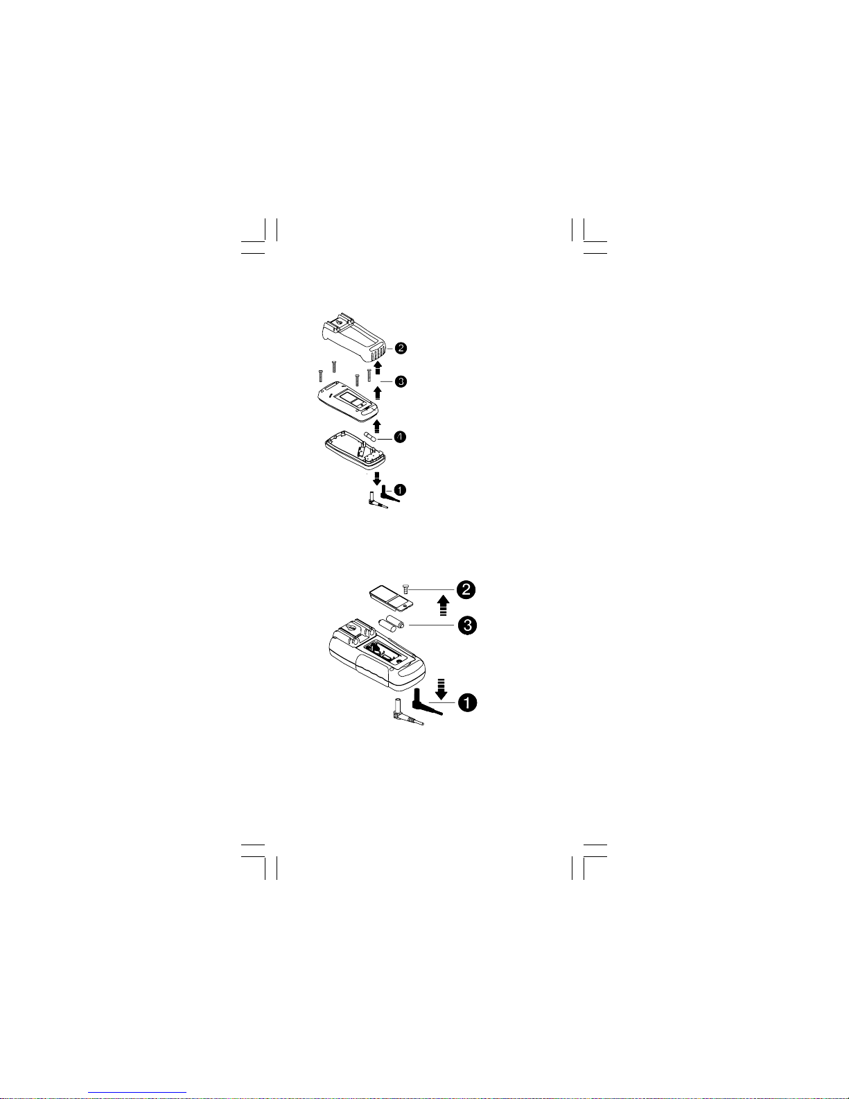
Fuse Replacement (For 352 & 354 only)
Refer to the following figure to replace fuse :
Battery Replacement
Refer to the following figure to replace the
batteries :
Caution
․ Replace the batteries as soon as the low
batteries indicator "" appears, to avoid false
reading.
․ Batteries 1.5V x 2
Caution
․ Use only a fuse with
the amperage, interrupt,
voltage, and speed
rating specified.
․ Fuse rating : 10A, 500V
Page 12

12
Specifications
General Specifications
Display : 2000 counts updates 1.5/sec.
Polarity Indication : Automatic, positive implied,
negative indicated.
Overrange Indication : “OL” or “-OL”.
Batteries Life : Alkaline 250 hours
Low Batteries Indication : “” is displayed
when the batteries voltage drops below
operating voltage.
Auto Power Off : Approx 10 minutes.
Operating Ambient : Non-condensing ≦50°F,
51.8°F ~ 86°F (≦80% R.H) 87.8°F ~ 104°F (≦75%
R.H), 105.8°F ~ 122°F (≦45% R.H),
Storage Temperature : -4°F to 140°F , 0 to
80% R.H. when battery removed from Meter.
Temperature Coefficient :
0.15 x (Spec.Accy) / °F ,< 64.4°F or > 82.4°F.
Power Requirements :
1.5V x 2 IEC LR03, AM4 or AAA size
Dimensions (W x H x D) :
2.91 in. x 6.14 in. x 1.34 in. without holster.
3.15 in. x 6.45 in. x 1.73 in. with holster.
Accessories : Battery (installed), Test leads
and user manual.
Measure : Samples 2 times per second nominal.
Altitude : 6561.7 ft (2000m)
Safety : Complies with EN61010-1, UL61010-1,
IEC 61010-1, CAT.III. 600V, CAT.II. 1000V.
Weight : 11.3 oz (320g) including battery.
Maintenance
Do not attempt to repair this Meter. It contains
no user-serviceable parts. Repair or servicing
should only be performed by qualified personnel.
Cleaning
Periodically wipe the case with a dry cloth and
detergent. Do not use abrasives or solvents.
Page 13
13
Electrical Specifications
Accuracy is ±(% reading + number of digits) at
23°C ± 5°C < 80%RH.
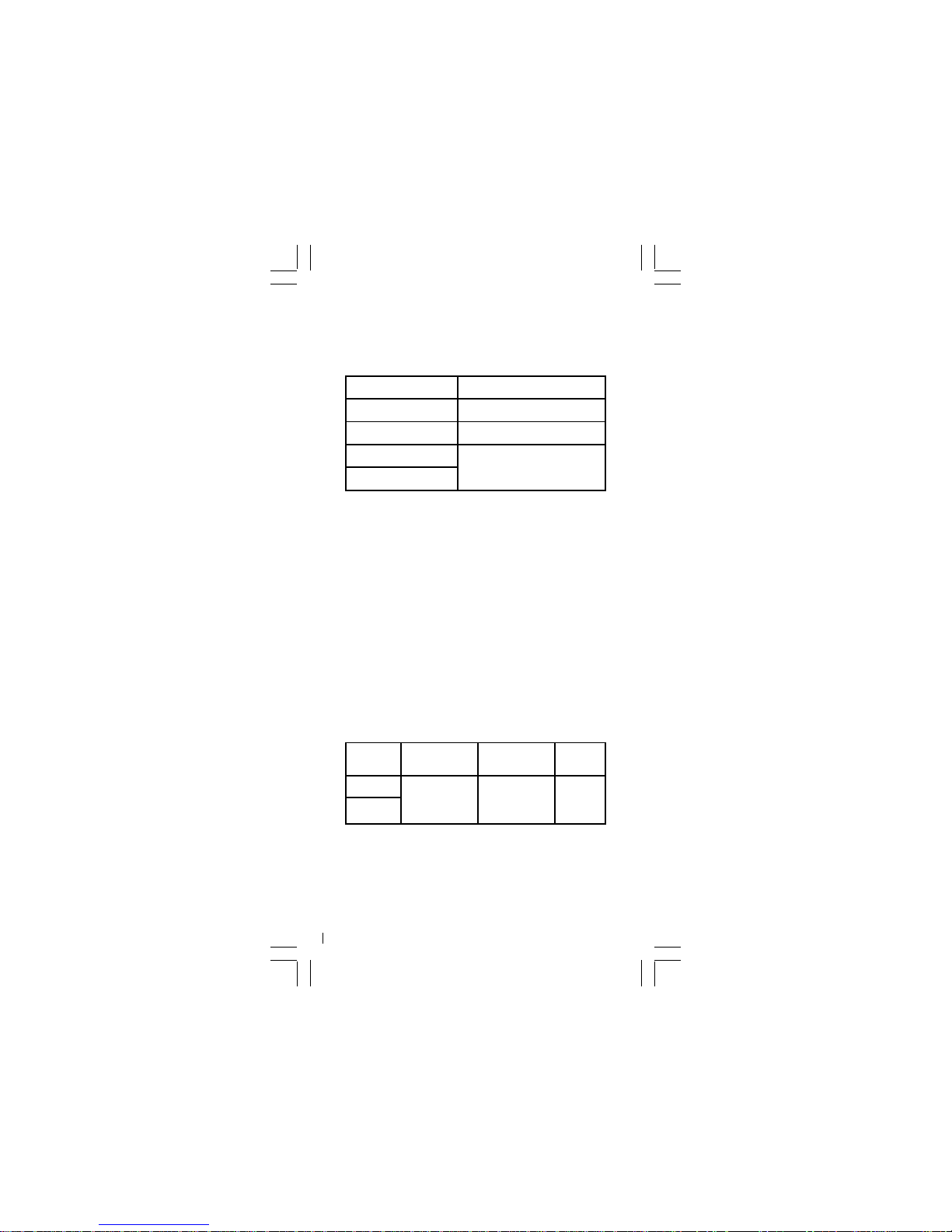
DC / AC Volts
Range AC Accuracy
200.0mV * Unspecified
2.000V *
± (1.5%+5dgt) 50Hz~300Hz
20.00V ~ 200.0V *
± (1.5%+5dgt) 50Hz~500Hz *
750V AC / 1000V DC
DC Accuracy : ±(0.5% + 2dgt)
Over voltage protection :
1000V DC or 750 V AC rms.
Input Impedance : 10MΩ // less than 100pF.
* CMRR / NMRR :
(Common Mode Rejection Ratio)
(Normal Mode Rejection Ratio)
V
AC
: CMRR > 60dB at DC, 50Hz / 60Hz
V
DC
: CMRR > 100dB at DC, 50Hz / 60Hz
NMRR > 50dB at DC, 50Hz / 60Hz
AC Conversion Type :
Average sensing rms indication.
AC conversions are ac-coupled, true rms
responding, calibrated to the sine wave input.
* The minimum LCD reading is 1400 count in Auto
Ranging Mode.
Crest Factor : C.F. = Peak / Rms
+ 1.5% addition error for C.F. from 1.4 to 3
+ 3% addition error for C.F. from 3 to 4
DC / AC Current (For 352 & 354 only)
Range DC Accuracy AC Accuracy
Voltage
Burden
±(1.0% + 3 dgt)
±(1.5% + 5 dgt)
50Hz ~ 500Hz
*
2V max
2.000A
10.00A **
Overload Protection :
A input : 10A (500V) fast blow fuse
* AC Conversion Type : Conversion type and
additional specification are same as DC/AC Voltage.
* * Maximum input current restriction time :
10 minutes.
Page 14
14
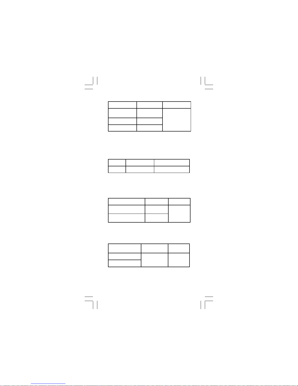
Resistance
Diode Check and Continuity
Range Accuracy Voltage Burden
200.0 ~ 200.0KΩ
**
±(0.7% + 3 dgt)
2.000MΩ ** ±(1.0% + 3 dgt)
20.00MΩ * ±(1.5% + 3 dgt)
2V max
Range Resolution Accuracy
10 mV
±(1.5% + 5 dgt)*
* For 0.4V ~ 0.8V
Max.Test Current : 1.5mA
Max. Open Circuit Voltage : 2V
Overload Protection : 600V rms.
Frequency (For 352 & 354 only)
Overload Protection : 600V rms.
Minimum pulse width : >25 ns
Duty cycle limits : >30% and <70%
Capacitance (For 352 & 354 only)
Range Sensitivity Accuracy
2000Hz ~200.0KHz
>1.5 Vac rms,
<5 Vac rms
Frequency :
0.01%±1digit
2.000MHz ~ 20.00MHz
>2 Vac rms,
<5 Vac rms
Range Accuracy
2.000nF ~ 200.0µF
±(1.9% + 8 dgt)
2.000mF *
Overload
Protection
600V rms
* < 100 dgt of reading rolling.
Open circuit Voltage : -1.3V approx.
* <100 dgt rolling.
* * The minimum LCD reading is 1400 count in
Auto Ranging Mode.
Page 15

15
Lifetime Limited Warranty
This meter is warranted to the original purchaser
against defects in material or workmanship for the
lifetime of the meter. During this warranty period,
IDEAL INDUSTRIES, INC. will, at its option,
replace or repair the defective unit, subject to
verification of the defect or malfunction.
This warranty does not apply to defects resulting
from abuse, neglect, accident, unauthorized repair,
alteration, or unreasonable use of the instrument.
Any implied warranties arising out of the sale of an
IDEAL product, including but not limited to implied
warranties of merchantability and fitness for a
particular purpose, are limited to the above.
The manufacturer shall not be liable for loss of use
of the instrument or other incidental or consequential damages, expenses, or economic loss, or for
any claim or claims for such damage, expenses or
economic loss.
State laws vary, so the above limitations or
exclusions may not apply to you. This warranty
gives you specific legal rights, and you may also
have other rights which vary from state to state.
IDEAL INDUSTRIES, INC.
Sycamore, IL 60178, U.S.A.
877-201-9005 Technical Support
www.testersandmeters.com
ND–5499 Made in Taiwan
Page 16

16
IDEAL INDUSTRIES, INC.
Sycamore, IL 60178, U.S.A.
877-201-9005 Technical Support
www.testersandmeters.com
ND–5499 Made in Taiwan
Page 17

17
Multímetro digital
Serie 350
#61-350
#61-352
#61-354(TRMS)
Page 18

18
Características
Detección de escala automática/manual
Voltaje sin contacto (NCV) 80-600 VCA
Mide corriente de CA/CC (sólo 352 y 354)
Mide voltaje de CA/CC y resistencia
Mide frecuencia y capacitancia (sólo 352 y 354)
Continuidad audible
Retención de datos
Indicación de baterías descargadas
Apagado automático
Números y símbolos de gran tamaño
Protección electrónica contra sobrecarga en
todas las escalas
Warning
. . . . . . . . . .
. . . . . . . . . .
. . . . . . . . . .
. . . . . . . .
Safety sheet
. . . . . . . . .
. . . . . . . . . .
. . . . . . . . . .
. . . . . . . .
. . . . . . . . .
2 Lea primero
ADVERTENCIA
Para evitar posibles riesgos de electrocución,
lesiones principales o la muerte, siga estas
pautas :
No use el instrumento si parece estar dañado.
Inspecciónelo visualmente para asegurarse de
que la cubierta no esté fisurada y que la parte
posterior de la misma esté firmemente fijada en
su sitio.
● Inspeccione y reemplace los cables si el
aislamiento está dañado, hay partes metálicas
expuestas o las sondas están fisuradas. Preste
particular atención al aislamiento de alrededor
de los conectores.
● No use el instrumento si funciona en forma
anormal, porque puede disminuirse la protección.
● No use el instrumento durante tormentas
eléctricas o con tiempo húmedo.
● No use el instrumento cerca de gases
explosivos, polvo o vapor.
● No aplique al instrumentos voltajes superiores
al nominal.
● No use el instrumento sin las baterías y la parte
posterior de la cubierta correctamente
instaladas.
Page 19

19
● Retire los cables de prueba del circuito antes de
desmontar la tapa de las baterías.
● No intente reparar esta unidad, puesto que no
contiene piezas reparables por el usuario.
● Los voltajes superiores a 30 VCA o 60 VCC
representan un riesgo de electrocución, por lo
que debe trabajar con precaución.
PRECAUCIÓN
Para protegerse, piense que “ La seguridad
primero!”:
● Use equipos de protección personal apropiados,
tales como gafas de seguridad, máscaras faciales,
guantes, calzado y/o alfombras aislantes.
● Antes de cada uso.
- Realice una prueba de continuidad poniendo en
contacto los cables de prueba para verificar el
funcionamiento de las baterías y los cables.
- Use el método de seguridad de 3 puntos.
(1) Verifique el funcionamiento del instrumento
midiendo un voltaje conocido.
(2) Aplique el instrumento al circuito en prueba.
(3) Vuelva al voltaje conectado conocido para
asegurarse de que el funcionamiento es
correcto.
● No se conecte a tierra cuando tome medidas
eléctricas.
● Conecte el cable negro común a tierra o al
neutro antes de aplicar el cable rojo al voltaje
potencial.
Desconecte primero el cable rojo del voltaje.
● Trabaje siempre con un compañero.
● Cuando use las sondas, mantenga los dedos
tan lejos de las puntas de las mismas como sea
posible.
● Nunca conecte una fuente de voltaje con el
conmutador rotativo de funciones en las
posiciones Ω/ :</ A //Hz .
● Nunca coloque el instrumento en la función
A para medir el voltaje de un circuito de
fuente de alimentación de un equipo que pueda
producir daños al instrumento y al equipo en
prueba.
Page 20

20
Riesgo de electrocución
Vea la tarjeta de instrucciones
Medida de CC
Equipo protegido por aislamiento doble
o reforzado
Batería
Fusible
Tierra
Medida de CA
Cumple las directivas de la UE
Símbolos marcados en el instrumento y en
la tarjeta de instrucciones
Page 21

21
Medición de voltaje de CA/CC y
frecuencia
Page 22

22
Resistencia
Prueba de continuidad
/630V 1 F
Descargue el capacitor
Alimentacion del circuito
Desconecte
desconectada
de alto voltaje
Page 23

23
Medición de corriente de CC / CA
(sólo 352 y 354)
Desconecte
Prueba de diodos
Negro
Rojo
Rojo
Negro
Diodo en buen estado
Diodo defectuoso
Rojo
Negro
Rojo
Negro
Page 24

24
Registro de MÍN y MÁX
Pulse
1 seg
1 seg
Pulse
Pulse
Pulse
Pulse
Medición de capacitancia
(sólo 352 y 354)
Page 25

25
Retención de pantalla
Pulse
Pulse
Apagado automático
(Economizador de baterías)
10 min
Selección manual y detección
automática de escala
Pulse
Pulse 1 seg
Pulse
Pulse
Pulse 1 seg
Pulse 1 seg
Page 26

26
Desactivación del apagado automático
NCV
Pulse
1. El interruptor de NCV se activa con cualquier
función o en estado de apagado.
2. En la prueba de voltaje sin contacto no se usan
los cables de prueba.
3. Pulse el botón NCV. La pantalla se oscurece,
suena un tono y el LED rojo se enciende para
verificar que el instrumento está en
funcionamiento. Para detectar la presencia de
voltaje sin usar los cables, debe mantenerse
oprimido el botón NCV.
Voltaje sin contacto (NCV)
Page 27

27
Reemplazo del fusible (sólo 352 y 354)
Para reemplazar el fusible, consulte la figura
siguiente:
Precaución
․ Use sólo un fusible
de la clasificación de
amperaje, interrupción,
voltaje y velocidad
especificada.
․ Clasificación del
fusible : 10A, 500V
Reemplazo de baterías
Para reemplazar las baterías, consulte la figura
siguiente:
Precaución
․ Para evitar lecturas falsas, reemplace las
baterías tan pronto aparezca el indicador de
batería descargada "".
․ 2 baterías de 1.5 V
Page 28

28
Mantenimiento
No intente reparar este multímetro. No contiene
partes reparables por el usuario. La reparación
o el servicio debe efectuarlos personal calificado.
Limpieza
Limpie periódicamente la cubierta con un paño
seco y detergente. No use abrasivos ni disolventes.
Especificaciones
Especificaciones generales
Pantalla : 2000 unidades actualización 1.5/seg.
Indicación de polaridad : Automática, positivo
implícito y negativo indicado.
Indicación de fuera de rango: “OL” o “-OL”
Vida útil de las baterías : Alcalinas 250 horas
Indicación de baterías descargadas :
“” se muestra cuando el voltaje de las baterías
cae por debajo del voltaje de funcionamiento.
Apagado automático : Aprox. 10 minutos.
Ambiente operacional : Sin condensación
≦50°F (10°C), 51.8°F ~ 86°F (11 ~ 30°C) (H.R. ≦
80%) 87.8°F ~ 104°F(31 ~ 40°C) (H.R. ≦75%),
105.8°F ~ 122°F (41 ~ 50°C) (H.R. ≦45%)
Temperatura de almacenamiento:
-4°F a 140°F (-20 a 60°C) , 0 to 80% H.R.
cuando se retira la batería del instrumento.
Coeficiente de temperatura:
0.15 x (prec. espec.) / °F ,< 64.4°F o > 82.4°F.
Requisitos de energía:
2 IEC de 1.5 V IEC tamaños LR03, AM4 o AAA
Dimensiones (ancho x alt. x prof.) :
2.91x6.14x1.34 pulg. (74x156x34) sin estuche.
3.15x6.45x1.73 pulg. (80x164x44 mm) con
estuche.
Accesorios : Batería (instalada), cables de
prueba y manual del usuario.
Medida : Muestreo nominal 2 veces por segundo.
Altitud : 6561.7 pies (2000 m)
Seguridad : Cumple las normas EN61010-1,
UL61010-1, IEC 61010-1, CAT.III. 600V, CAT.II.
1000 V.
Peso : 11.3 onzas (320 g) incluida la batería.
Page 29

29
Especificaciones eléctricas
La precisión es ±(% lectura + número de dígitos)
a 23°C ± 5°C HR < 80%.
Voltaje de CC / CA
Rango Precisión en CA
200.0mV * Sin especificar
2.000V *
± (1.5%+5dgt) 50Hz~300Hz
20.00V ~ 200.0V *
± (1.5%+5dgt) 50Hz~500Hz *
750V CA / 1000V CC
Precisión en CC : ±(0.5% + 2 dgt)
Protección contra sobrevoltaje :
1000 VCC o 750 VCA ef.
Impedancia de entrada :
10 MΩ // menos de 100 pF.
* CMRR / NMRR :
(Relación de rechazo de modo común)
(Relación de rechazo de modo normal)
VCA : CMRR > 60 dB en CC, 50 Hz / 60 Hz
VCC : CMRR > 100 dB en CC, 50 Hz / 60 Hz
NMRR > 50 dB en CC, 50 Hz / 60 Hz
Tipo de conversión de CA:
Indicación de valor eficaz (RMS) con sensado de
promedio Las conversiones de CA son con
acoplamiento de CA, con respuesta de valor
eficaz verdadero y calibradas a la entrada de
onda senoidal.
* La lectura mínima de la pantalla LCD es 1400
unidades en modo de detección automática de
escala.
Factor de cresta: C.F. = Valor pico / Valor eficaz
error adicional de + 1.5% para C.F. de 1.4 a 3
error adicional de +3% para C.F. de 3 a 4
Corriente de CC / CA (sólo 352 y 354)
Rango
Precisión en
CC
Precisión en
CA
Carga de
voltaje
±(1.0%+3 dgt)
±(1.5%+5 dgt)
50Hz ~ 500Hz
*
2V max
2.000A
10.00A
**
Page 30

30
Protección contra sobrecarga :
Entrada A : Fusible de fusión rápida de 10 A
(500 V)
* Tipo de conversión de CA :
El tipo de conversión y la especificación adicional
son las mismas del voltaje de CC/CA.
* * Máximo tiempo de restricción de corriente
de entrada : 10 minutos.
Resistencia
Rango Precisión
Carga de
voltaje
200.0 ~ 200.0KΩ ** ±(0.7% + 3 dgt)
2.000MΩ ** ±(1.0% + 3 dgt)
20.00MΩ * ±(1.5% + 3 dgt)
2V máx
Voltaje a circuito abierto : -1.3 V aprox.
* oscilación <100 dgt.
* La lectura mínima de la pantalla LCD es 1400
unidades en modo de detección automática de
escala.
Comprobación de diodos y continuidad
Rango Resolución Precisión
10 mV
±(1.5% + 5 dgt)*
* Para 0.4 V ~ 0.8 V
Máx. corriente de prueba : 1.5 mA
Máx. voltaje a circuito abierto : 2 V
Protección contra sobrecarga : 600 V ef.
Frecuencia (sólo 352 y 354)
Rango Sensibilidad Precisión
2000Hz~200.0KHz
>1.5 V CA ef,
<5 V CA ef
Frecuencia :
0.01%±1dígito
2.000MHz~20.00MHz
>2 V CA ef,
<5 V CA ef
Protección contra sobrecarga: 600 V ef.
Mínimo ancho de pulso: > 25 ns
Límites del ciclo de trabajo: > 30% y < 70%
Page 31

31
Capacitancia (sólo 352 y 354)
Rango Precisión
2.000nF~200.0µF
±(1.9%+8 dgt)
2.000mF *
Protección de
sobrecarga
600V ef
* oscilación de la lectura <100 dgt.
Page 32

32
IDEAL INDUSTRIES, INC.
Sycamore, IL 60178, U.S.A.
877-201-9005 Soporte Técnico
www.testersandmeters.com
ND–5499 Fabricado en Taiwán
Garantía limitada de por vida
Se garantiza este instrumento al comprador
original contra defectos de material y mano de
obra durante la vida útil del instrumento. Durante
este período de garantía, IDEAL INDUSTRIES,
INC. podrá, a la sola opción de IDEAL,
reemplazar o reparar la unidad defectuosa, sujeto
a verificación del defecto o falla.
Esta garantía no se aplica a defectos resultantes
del mal uso, negligencia, accidente, reparación
no autorizada, alteración o uso irracional de este
instrumento.
Cualquier garantía implícita originada en la venta
de un producto IDEAL, incluidas —pero sin
limitarse a ellas— las garantías implícitas de
comerciabilidad y adecuación para un propósito
particular, se limitan a lo indicado anteriormente.
El fabricante no será responsable por la pérdida
del uso del instrumento u otros daños y perjuicios
incidentales o consecuentes, gastos o pérdidas
económicas, ni por ninguna reclamación de
dichos daños y perjuicios, gastos o pérdidas
económicas.
Las leyes estatales varían, por lo que las
limitaciones o exclusiones anteriores pueden no
aplicarse en su caso. Esta garantía le da
derechos legales específicos y puede tener otros
derechos que varían de estado a estado.
Page 33

33
#61-350
#61-352
#61-354(TRMS)
Multimètre numérique
Série 350
Page 34

34
Caractéristiques
Mesures en Auto / Manuel
Tension sans contact (NCV) 80-600 V CA
Mesures de courant CA/CC
(352 et 354 seulement)
Mesures de tension CA/CC et de résistance
Mesures de fréquence et de capacitance
(352 et 354 seulement)
Continuité audible
Maintien des données
Indication de piles faibles
Coupure automatique
Chiffres élevés et symboles
Protection électronique contre surcharge sur
toutes gammes
Warning
. . . . . . . . . .
. . . . . . . . . .
. . . . . . . . . .
. . . . . . . .
Safety sheet
. . . . . . . . .
. . . . . . . . . .
. . . . . . . . . .
. . . . . . . .
. . . . . . . . .
2 À lire en premier
2 Informations de sécurité
Assimilez et suivez scrupuleusement les
instructions d'utilisation. N'utilisez l'appareil que
comme spécifié dans ce manuel, sinon la
protection qu'il fournit peut être détériorée.
AVERTISSEMENT
Pour éviter une possible commotion électrique,
des blessures ou même la mort, suivez ces
directives :
● N'utilisez pas l'appareil s'il semble endommaé,
inspectez-le visuellement pour vérifier que son
boîtier n'est pas fendu et que son enveloppe
arrière est bien en place.
● Inspectez et remplacez les cordons si l'isolation
est dégradée, le métal exposé ou les sondes
cassées. Faites particulièrement attention à
l'isolation autour des connecteurs.
● N'utilisez pas l'appareil s'il ne fonctionne pas
normalement car sa protection peut être
déficiente.
● Ne l'utilisez pas durant des orages ou par temps
de pluie.
Page 35

35
● Ne l'utilisez pas en présence de gaz, poussière
ou vapeur explosifs.
● N'appliquez pas de tension supérieure à la
valeur nominale de l'appareil.
● Ne l'utilisez pas sans piles et enveloppe arrière
correctement installée.
● Enlevez les cordons de test du circuit avant
d'ôter le couvercle des piles.
● N'essayez pas de réparer cet appareil car il n'a
pas de pièces dépannables.
● Les tensions dépassant 30 V CA ou 60 V CC
présentent un risque de commotion électrique,
restez donc prudent.
ATTENTION
Pour vous protéger, pensez sécurité d'abord :
● Utilisez un équipement de protection personnelle
approprié comme lunettes de sécurité, masque
facial, gants et bottes isolants et/ou tapis
isolants.
● Avant chaque utilisation :
- Effectuez un test de continuité en joignant les
extrémités des cordons de test pour vérifier le
bon état des piles et des cordons de test.
- Utilisez la méthode de sécurité en 3 points.
(1) Vérifiez le bon fonctionnement de l'appareil
en mesurant une tension connue. 2) Appliquez
l'appareil sur le circuit en test. (3) Revenez sur la
tension connue pour valider la mesure.
● Ne vous mettez jamais à la terre vous-même en
effectuant des mesures électriques.
● Connectez le cordon noir de commun à la terre
ou au neutre avant d'appliquer le cordon rouge
de test sur la tension potentielle.
A la fin débranchez le cordon rouge de test en
premier.
● Travaillez toujours avec un collègue.
● En utilisant les sondes, gardez les doigts le plus
loin possible de leurs extrémités.
● Ne vous branchez jamais sur une source de
tension avec le commutateur rotatif sur une des
positions Ω/ :</ A //Hz .
● Ne positionnez jamais l'appareil sur la fonction
A pour mesurer la tension d'un circuit
d'alimentation de l'équipement qui pourrait
endommager l'appareil et l'équipement testé.
Page 36

36
Symboles présents sur l'appareil et sa
feuille d'instructions
Risque d'électrocution
Voir la feuille d'instructions
Mesure en continu (CC)
Équipement protégé par isolation double
ou renforcée
Piles
Fusible
Terre
Mesure en alternatif (CA)
Conforme au directives de l'Union
Européenne
Page 37

37
Mesure de tension CA/CC et de
fréquence
Page 38

Résistance
Test de continuit é
/630V 1 F
Decharger le condensateur
Couper I'alimentation
Debrancher
secteur
haute tension
'
'
Page 39

Mesure de courant CC/CA
(Pour 352/354 seulement)
Debrancher
'
Test de diode
Noir
Rouge
Rouge
Noir
Diode bonne
Diode defectueuse
Rouge
Noir
Rouge
Noir
'
Page 40

40
Enregistrement de valeurs MIN MAX
Appuyer
1 sec
Appuyer
Appuyer
Appuyer
1 sec
Appuyer
Mesure de capacitance
(Pour 352/354 seulement)
Page 41

41
Maintien de l'affichage
Appuyer
Appuyer
Coupure automatique
(économie de piles)
10 min
Passage en modes Manuel et Auto
Appuyer
1 sec
Appuyer
Appuyer
Appuyer
1 sec
Appuyer
1 sec
Appuyer
Page 42

42
Désactivation de la coupure
automatique
NCV
Pulse
1. Le commutateur NCV sera activé pour
chaque fonction ou à l'état d'arrêt.
2. Les cordons de test ne sont pas utilisés pour
les mesures en NCV.
3. Appuyez sur le bouton NCV. L'affichage
devient noir, une tonalité retentit et les
voyants DEL rouges s'allument pour montrer
que l'instrument est opérationnel. Le bouton
NCV doit être maintenu appuyé pour détecter
la présence de tension sans utiliser les
cordons.
Mesure de tension sans contact
(NCV)
Page 43

43
Remplacement des fusibles (Pour 352/354
seulement)
Reportez-vous au schéma suivant pour
remplacer le fusible :
Attention
● N'utilisez qu'un fusible
ayant ampérage,
tension d'interruption
et Vitesse de fusion
conformes aux
spécifications.
● Spécifications de
fusible : 10 A, 500 V
Replacement des piles
Reportez-vous au schéma suivant pour
remplacer les piles:
Attention
․ Remplacez les piles dès que l'indicateur ""
de charge faible de piles apparaît, pour éviter
des mesures erronées.
․ 2 piles de 1,5 V
Page 44

44
Entretien
N'essayez pas de réparer ce multimètre. Il ne
contient pas de pièces réparables. Les remises
en état ou interventions ne doivent être effectuées
que par du personnel qualifié.
Nettoyage
Essuyez de temps en temps le boîtier avec un
linge sec et du détergent. N'utilisez pas de
produits abrasifs ni de solvants.
Spécifications
Spécifications générales
Affichage : 2 000 rafraîchissements -1,5/sec.
Indication de polarité : Automatique, positif
sous-entendu, Négatif indiqué.
Indication de dépassement : “OL” ou “-OL”.
Durée des piles :
250 heures pour des al calines
Batteries Indication de piles faibles :
“” est affiché si la tension des piles tombe
sous le niveau opérationnel.
Coupure automatique :
Après environ 10 minutes sans action.
Ambiance de fonctionnement :
≤ 50 °F sans condensation, 51,8 °F ~ 86 °F
(≤ 80% H.R.) 87,8 °F ~ 104 °F (≤ 75% H.R.),
105,8 °F ~ 122 °F (≤ 45% H.R.)
Température de stockage :
-4 °F à 140 °F, 0 à 80% d'humidité Relative
avec piles ôtées de l'appareil.
Coefficient de température : 0,15 x (précision
spécifiée) / °F,< 64,4 °F ou > 82,4 °F.
Besoins en alimentation :
2 piles 1,5V de type IEC LR03, AM4 ou AAA.
Dimensions (L x H x P) :
2,91 x 6,14 x 1,34 pouces sans étui.
3,15 x 6,45 x 1,73 pouces avec étui.
Accessoires : Piles (installée), cordons de test
et manuel d'utilisation.
Mesure nominale :
2 échantillonnages par seconde.
Altitude max. : 6 561,7 pieds (2 000 m)
Sécurité :
Conformité avec EN61010-1, UL61010-1, IEC
61010-1, CAT.III. 600 V, CAT.II. 1 000 V.
Poids : 11,3 oz (320 g) avec piles.
Page 45

45
Spécifications électriques
La précision est de ± (% lecture + nombre de
chiffres) à 23 °C ± 5 °C et < 80% H.R.
Volts CC/AC
Calibre Précision CA
200.0mV * Non spécifiée
2.000V *
± (1.5%+5 chiffres) à
50 ~300Hz
20.00V ~ 200.0V *
± (1.5%+5 chiffres) à
50Hz~500Hz *
750V CA / 1000V CC
Précision CC : ± ( 0.5% + 2 chiffres)
Protection en surtension :
1 000 V CC ou 750 V CA efficaces.
Impédance d'entrée :
10 MΩ avec moins de 100 pF.
* CMRR / NMRR :
(Taux de réjection en mode commun)
(Taux de réjection en mode normal)
VCA : CMRR > 60 dB pour CC, 50 Hz / 60 Hz
VDC : CMRR > 100 dB pour CC, 50 Hz / 60 Hz
NMRR > 50 dB pour CC, 50 Hz / 60 Hz
Type de conversion pour CA :
Indication de détection efficace moyenne.
Les conversions CA sont couplées en CA, avec
réponse en efficace vrai, calibrées sur une entrée
de signal sinusoïdal.
* La lecture minimum sur LCD est un comptage
de 1 400 en mode de mesure automatique.
Facteur de crête : F.C. = pointe / efficace
+ 1,5% d'erreur additionnée pour F.C. de 1,4 à 3
+ 3% d'erreur additionnée pour F.C. de 3 à 4
Courant CC/CA (Pour 352/54 seulement)
Calibre
Précision CC Précision CA
2.000A
±(1.0%+3 chiffres)
±(1.5%+5 chiffres)
50Hz ~ 500Hz *
10.00A
Tension absorbée : 2V max.
Page 46

46
Protection en surcharge :
Entrée A : Fusible à déclenchement rapide 10 A
(500 V)
* Type de conversion CA : Le type de
conversion et les spécifications additionnelles
sont les mêmes que pour la tension CC/CA.
* * Durée de restriction pour entrée maximale
de courant : 10 minutes.
Résistance
Calibre Précision
Tension
absorbée
200.0 ~ 200.0KΩ ** ±(0.7% + 3 chiffres)
2.000MΩ ** ±(1.0% + 3 chiffres)
20.00MΩ * ±(1.5% + 3 chiffres)
2V max
Tension en circuit ouvert : -1,3 V environ.
* Incertitude d'affichage<100 derniers chiffres.
* * La lecture minimum sur LCD est un comptage
de 1 400 en mode de mesure automatique.
Vérification de diode et de continuité
Calibre Résolution Précision
10 mV
±(1.5% + 5 dgt)*
Pour 0,4 V ~ 0,8 V
Courant max. de test : 1,5 mA
Tension max. en circuit ouvert : 2 V
Protection contre la surcharge : 600 V efficaces.
Fréquence (Pour 352/354 se ul em en t )
Rango Sensibilité Précision
2000Hz~200.0KHz
>1.5 V CA
efficaces
<5 V CA
efficaces
Fréquence :
0.01%±1chiffre
2.000MHz~20.00MHz
>2 V CA
efficaces,
<5 V CA
efficaces
Protection contre la surcharge :
600 V efficaces.
Page 47

47
Largeur minimum d'impulsion : >25 ns
Limites de facteur de forme : >30% et <70%
Capacitance (Pour 352/354 seulement)
Calibre Précision
2.000nF~200.0µF
±(1.9%+8 chiffres)
2.000mF *
Protection
contre la
surcharge
600V
efficaces
* Incertitude d'affichage<100 derniers chiffres.
Garantie limitée à vie
Ce multimètre est garantie à l'acheteur d'origine
contre tous défauts dus aux matériaux ou à la
main d'œuvre pour toute sa durée de service.
Durant cette période de garantie IDEAL
INDUSTRIES, INC. procédera à son choix au
remplacement ou à la réparation de l'unité
défectueuse, sous réserve de la constatation de
défaut ou dysfonctionnement. Cette garantie ne
s'applique pas aux défauts résultant d'abus,
négligence, accident, réparation non autorisée,
altération, ou utilisation irresponsable de
l'appareil. Toutes les garanties implicites suite à
la vente d'un produit IDEAL, incluant mais sans
y être limité les garanties de valeur marchande
et d'adéquation à une finalité particulière, sont
limités aux conditions précédentes.
Le constructeur ne sera pas tenu pour
responsable pour la perte d'usage de l'appareil,
ni pour d'autres dommages accessoires ou
indirects, dépenses ou pertes financières, ni
pour toute(s) réclamation(s) ayant trait à de tels
dommages, dépenses ou pertes financières.
Les législations des états varient, de ce fait les
précédentes exclusions ou limitations peuvent
ne pas être applicables pour vous.
Cette garantie vous donne des droits légaux
spécifiques, et vous pouvez avoir d'autres droits
qui varient d'un état à l'autre.
Page 48

48
IDEAL INDUSTRIES, INC.
Sycamore, IL 60178, U.S.A.
877-201-9005 (Support technique)
www.testersandmeters.com
ND–5499 Fabriqué à Taïwan
 Loading...