

Page 1
IDEAL INDUSTRIES INC.
TECHNICAL MANUAL
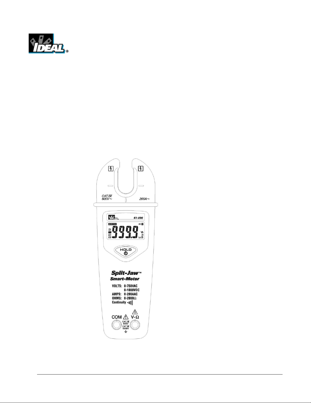
MODEL 61-096 Split Jaw Smart Meter
The Service Information provides the following information :
• Precautions and safety information
• Specifications
• Basic maintenance (cleaning, replacing the battery and fuses)
• Performance test procedures
• Calibration and calibration adjustment procedures
Form Number: TM61096
Revision: 2. Date: Nov 2010
Form Number TM61096 Rev 2 Nov 2010
Page 2

TABLE OF CONTENTS Page
Introduction
1
Precautions and Safety Information
1
Symbols
1
Safety
2
Specifications
3
General Specification
3
Voltage Specification
4
Resistance & Continuity Specification
4
Current Specification
4
Physical and environment characteristics
5
Certification and compliance
5
Required Equipment
6
Basic Maintenance
7
Opening the Meter Case
7
Replacing the Battery
7
Performance Tests
8
Testing the Voltage Function
8
Testing the Resistance Function
9
Testing the AC Current Function
10
Calibration
11
Calibrating DCV, ACV, Resistance, ACA Functions
11
Calibration Adjustment Points
12/13
Form Number TM61096 Rev 2 Nov 2010
i
Page 3
Introduction
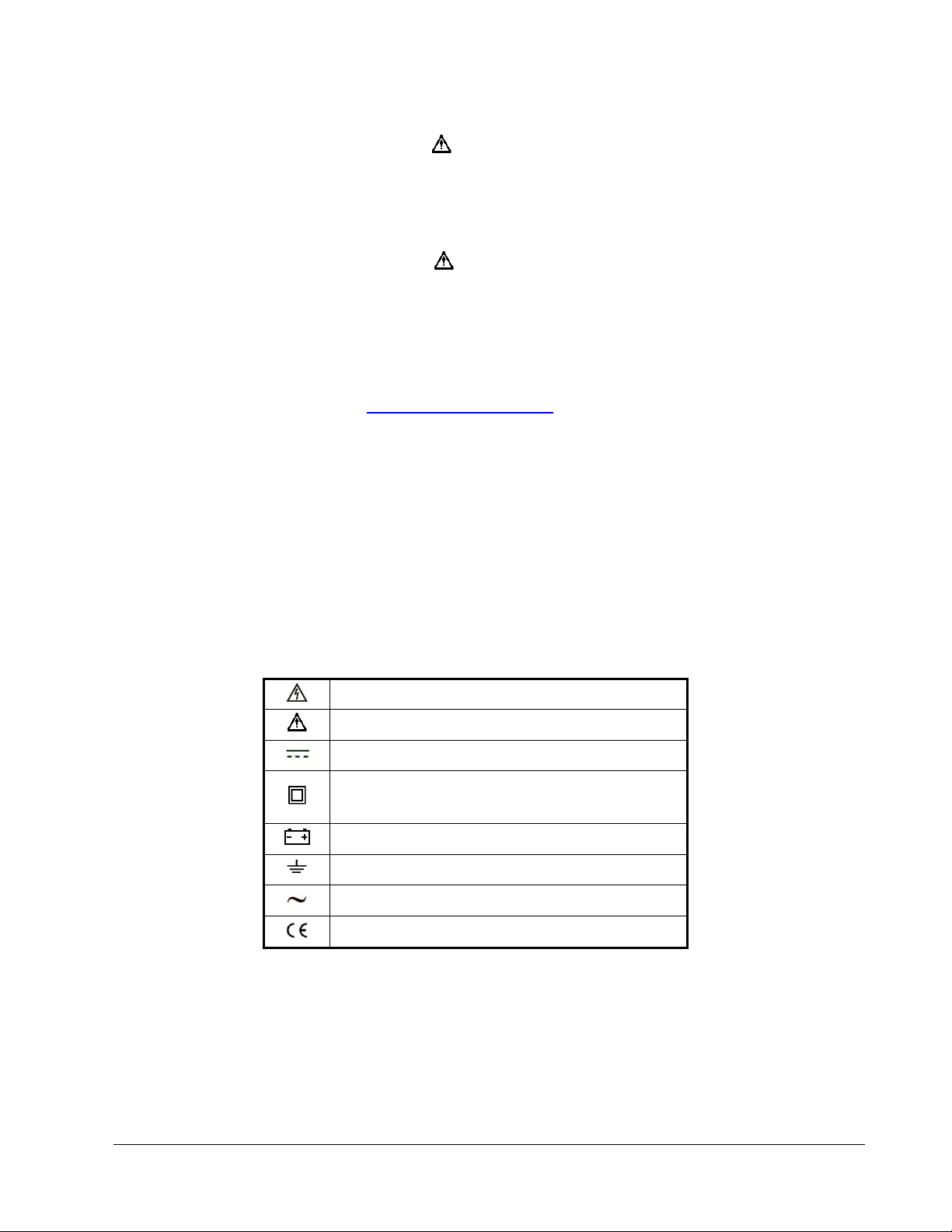
Risk of electric shock
See instruction card
DC measurement
Equipment protected by double or reinforced
insulation
Battery
Earth
AC measurement
Conforms to EU directives
Warning
To avoid shock or injury, do not perform the verification tests or calibration procedures
described in the manual unless you are qualified to do so.
The information provided in this document is for the use of qualified personnel only.
Caution
The 61-096 contain parts that can be damaged by static discharge.
Follow the standard practices for handling static sensitive devices.
For additional information about IDEAL INDUSTRIES, INC. and its products, and services, visit
IDEAL INDUSTRIES, INC. web site at:
www.idealindustries.com
Precautions and Safety Information
Use the Meter only as described in the Service Manual. If you do not do so, the protection provided by the
Meter may be impaired. Read the “Safety Information” page before servicing this product.
In this manual, a Warning identifies conditions and actions that pose hazard (s) to the user; a Caution
identifies conditions and actions that may damage the Meter or the test instruments.
The Symbols
The symbols used on the Meter and in this manual are explained in Table 1.
Table A. The Symbols
Form Number TM61096 Rev 2 Nov 2010
1
Page 4

SAFETY
Review the following safety precautions to avoid injury and prevent damage to this product or products
connected to it. To avoid potential hazards, use the product only as specified.
CAUTION: These statements identify conditions or practices that could result in damage to the
equipment or other property.
WARNING: These statements identify conditions or practices that could result in personal injury or
loss of life.
Specific precautions
Do not operate without covers. To avoid personal injury, do not apply any voltage or current to the
product without covers in place.
Electric overload. Never apply a voltage to a connector on the product that is outside the range
specified for that connector.
Avoid electric shock. To avoid injury or loss of life, do not connect or disconnect probes or test leads
while they are connected to a voltage source.
Do not operate in wet/damp conditions. To avoid electric shock, do not operate this product in wet or
damp conditions.
2
Form Number TM61096 Rev 2 Nov 2010
Page 5
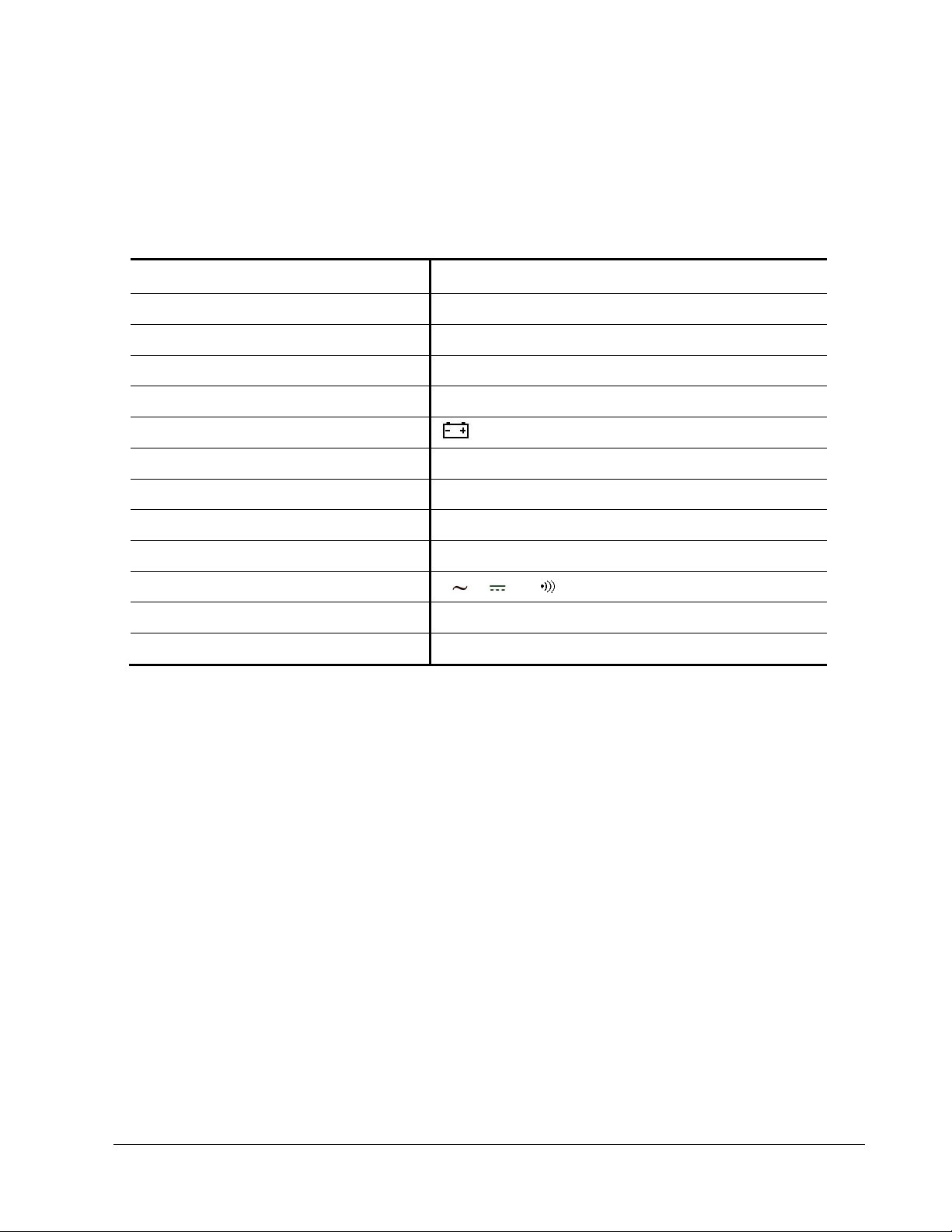
SPECIFICATIONS
Characteristics
Description
Display count
6000
Numeric update rate
5 times / sec
Polarity display
Automatic
Overrange display
“OL” is display
Low voltage indicator
is indicated
Automatic power-off time
Automatic backslit off = 30 minutes
Power source
Power 9V battery
Maximum input voltage
1000V CAT III between V and COM
Maximum floating voltage
1000V CAT III between any terminal and earth ground
V connector
V , V , Ω,
Temperature Coefficient
0.2×(Spec. Accuracy) / °C, <18°C or >28°C
Battery Life
180 hours typical (alkaline)
All specifications are warranted unless noted typical and apply to the 61-096
Stated accuracies are at 23°C±5°C at less than 80% relative humidity and without the battery indicator
displayed.
General specifications
3
Form Number TM61096 Rev 2 Nov 2010
Page 6

Measurement Characteristics
Function
Range
Accuracy
V
1.3V ~ 750.0V
±(1.5% reading + 3 digits)
50Hz ~ 500Hz
V
1.8V ~ 1000V
±(1% reading + 2 digits)
-0.6V ~ -1000V
±(1% reading + 4 digits)
Function
Range
Accuracy
Ω
0.0Ω ~ 99.9Ω
±(2% reading + 1Ω)
100Ω ~ 2000Ω
±(2% reading + 2 digits)
Function
Range
Accuracy
A
0.6A ~ 200.0A
±(1.8% reading + 3 digits)*
50Hz ~ 60Hz
Accuracy is ±(% reading + number of digits) at 23°C ± 5°C, less than 80% R.H.
DC / AC Volts
Overload protection: 750Vrms // 1000VDC
Max. Operation time: DT=30s for ≥ 30V
Input Impedance: ≥ 4K for input voltage up to 30V. Impedance increase with input voltage to 330KΩ at
1000V.
Resistance & Continuity
Overload protection: 750Vrms // 1000VDC
Max. Open Voltage: 1.5V
Continuity check: Internal sounds activates if the resistance of the circuit under test is less than 25Ω.
It will then turn off if the resistance is increased beyond 400Ω.
Operating temperature: 0°C ~ 40°C
AC Current
Overload protection: 400A
* ±(1.8% reading + 6 digits) ≤ 50A
Form Number TM61096 Rev 2 Nov 2010
4
Page 7

Physical and Environmental Characteristics
Characteristics
Description
Dimensions (W×H×L)
84mm×188mm×41mm
Weight (with battery)
230g
Environmental characteristics
Description
Temperature operating
0 to +50°C
Non-Operating
-20 to +60°C
Humidity (operating)
<80% R.H.
Altitude Operating
2,000M (6560 ft.)
Non-Operating
12,300M (40354 ft.)
Vibration & shock Operating
MIL-T-28800E TYPE II Class 5
2.66gRMS, 5 to 500 Hz, 3axes
(10 minutes each)
Indoor Use
Indoor Use
Safety
IEC 61010 and designed to meet UL 3111 specifications
Input rating
V / Ω: Category III 1000 Volts
Over voltage category
CAT III: Distribution level mains, fixed installation.
CAT II: Local level mains, appliances, portable equipment
CAT I: Signal level, special equipment or parts of equipment,
telecommunication, electronics.
Pollution Degree 2
Do not operate in environments where conductive
Pollutants may be present.
EC Declaration
of Conformity
Meets the intent of Directive 89/336/EEC for Electromagnetic
Compatibility and Low Voltage Directive 73/23/EEC for specifica tions as listed in the official Journal of the European Communites:
En 55011 Class A: Radiated and Conducted
Emissions.
En 50082-1 Immunity: IEC 801-2 Electrostatic Discharge
IEC 801-3 RF Radiated
En 61010-1 Safety requirements for electrical equipment for
measurement, control, and laboratory use.
Certifications and compliances
Form Number TM61096 Rev 2 Nov 2010
5
Page 8

Required Equipment
Equipment
Required Characteristics
Recommended Model
Calibrator
AC Voltage Range: 0 ~ 750V AC
Accuracy: ±0.07% (Basic)
Frequency Range: 40 ~ 1KHz
Accuracy: ±2%
DC Voltage Range: 0 ~ 1000V DC
Accuracy: ±0.006% (Basic)
Current Range: 0 ~ 10A
Accuracy: AC (40Hz to 1KHz): ±0.08% (Basic)
Resistance Range: 1Ω ~ 100MΩ
Accuracy: ±0.03% (Basic)
1. Fluke 5700A Calibrator
2. 50 Turns Coil
Required equipment is listed in Table B. If the recommended models are not available, equipment with
equivalent specifications may be used.
Repairs or servicing should be performed only by qualified personnel.
Table B. Required Equipment
Form Number TM61096 Rev 2 Nov 2010
6
Page 9

Basic Maintenance
Warning
To avoid shock, remove the test leads and any input signals before opening the case or replacing the
battery.
Opening the Meter Case
Caution
To avoid unintentional shock circuit, always place the uncovered Meter assembly on a protective
surface. When the case of the Meter is open, circuit connections are exposed.
To open the Meter case, and do the following:
1. Disconnect test leads from any live source, push the button to OFF, and remove the test leads from
the front terminals.
2. Remove the battery door by using a flat-blade screwdriver to turn the battery door screws turn
counter-clockwise.
3. The case bottom is secured to the case top by two screws. Using a Phillips-had screwdriver, remove
the two screws.
Replacing the Battery
The Meter powered by 9V battery for 61-096
To replace the battery refer to Figure.
Form Number TM61096 Rev 2 Nov 2010
7
Page 10

Performance Tests
Step
Input
Frequency
Reading
1
3.0V
50Hz
2.7 to 3.3
2
3.0V
500Hz
2.7 to 3.3
3
30.0V
50Hz
29.3 to 30.8
4
30.0V
500Hz
29.3 to 30.8
5
300.0V
50Hz
295.2 to 304.8
6
300.0V
500Hz
295.2 to 304.8
7
600.0V
50Hz
590.7 to 609.3
8
600.0V
500Hz
590.7 to 609.3
The following performance tests verify the complete operability of the Meter and check the accuracy of
each Meter function against the Meter’s specifications.
Accuracy specifications are valid for a period of one year after calibration, when measured at an
operating temperature of 18°C to 28°C and a maximum of 80% relative humidity.
To perform the following tests, it is not necessary to open the case, no Adjustments are necessary,
merely make the required connections, apply the designated inputs, determine if the reading on the
Meter display falls within the acceptable range indicated.
If the Meter fails any of these tests, it needs calibration adjustment or repair.
Testing the voltage Function
To verify accuracy in the AC and DC voltage ranges, do the following:
1. Push the button to start your meter.
2. Connect the Calibrator to the VΩ and COM inputs on the Meter.
3. Set the Calibrator for the voltage and frequency from step 1 to 8 in Table 1.
4. Compare the reading on the Meter display with the display reading shown in Table 1.
5. If the display reading falls outside of the range shown in Table 1, the Meter does not meet
specification.
Table 1 AC Voltage Test:
8
Form Number TM61096 Rev 2 Nov 2010
Page 11

6. Set the calibration for the voltage from step 1 to 8 in Table 2.
Step
Input
Reading
1
3.0V
2.8 to 3.2
2
-3.0V
-2.6 to -3.4
3
30.0V
29.5 to 30.5
4
-30.0V
-29.3 to -30.7
5
600.0V
593.8 to 606.2
6
-600.0V
-593.6 to -606.4
7
900.0V
890.8 to 909.2
8
-900.0V
-890.6 to -909.4
Step
Source
Reading
1
50.0Ω
48.9 to 51.1
2
500Ω
488 to 512
3
800Ω
782 to 818
4
1200Ω
1174 to 1226
5
1500Ω
1468 to 1532
6
2000Ω
1958 to 2042
7. Compare the reading on the Meter display with the display reading shown in Table 2.
8. If the display reading falls outside of the range shown in Table 2, the meter does not meet
specification.
Table 2 DC Voltage Test:
Testing the Resistance Function
To verify the accuracy of the resistance function, do the following:
1. Connect the calibrator to VΩ and COM on the Meter.
2. Push the button to start your Meter.
3. Apply the inputs for step 1-6 in Table 3.
4. Compare the Meter display readings to the display readings in Table 3.
5. If the display reading falls outside of the range shown in Table 3, the Meter does not meet
specification.
Table 3 Resistance Test:
Continuity check: Internal sounds activates if the resistance of the circuit under test is less the 25Ω. It
will then turn off if the resistance is increased beyond 400Ω
9
Form Number TM61096 Rev 2 Nov 2010
Page 12

Testing the AC Current Function
Step
Source
Frequency
Reading
1
100A
50Hz
97.9 to 102.1
2
100A
60Hz
97.9 to 102.1
3
200A
50Hz
196.1 to 203.9
4
200A
60Hz
196.1 to 203.9
To verify the accuracy of AC current measurement functions, do the following:
1. Open jaw of the meter around the suitable wire or conductor.
2. Push the button to start your meter.
3. Apply the inputs for steps 1-4 in Table 4.
4. For each input, compare the readings on the Meter display to the reading in Table 4.
5. If the display reading falls outside of the range shown in the Table 4, the meter does not meet
specification.
Table 4 AC Current Test:
10
Form Number TM61096 Rev 2 Nov 2010
Page 13

CALIBRATION PROCEDURE
Recalibrate your meter:
It is recommended that the meter may be calibrated once year. Use the following procedure to calibrate the
clamp meter.
1. Perform calibration at an ambient temperature and relative humidity (23°C±2°C and R.H.≤80%). Allow
instrument to sit at this temperature for at least thirty minutes.
2. Disconnect the test leads from any circuit under test and turn off meter.
3. Loosen the screws from the battery cover, remove battery cover and pull the battery out of battery box
with battery still connected.
4. Loosen the two screws from the bottom case.
5. Lift the bottom case.
(A) DCV Calibration (Adjust VR15)
1. Press Hold button of the meter to power on.
2. Set the output of calibrator for DCV 100V and connect to V and COM test probes.
3. Using a small flat-tip screwdriver adjust the potentiometer VR15 until display reads 100.1V~100.2V.
4. Disconnect the output terminals of DCV calibrator.
(B) Resistance Calibration (Adjust VR13 & VR14)
1. Set the output of calibrator for resistance 1KΩ and connect to V and COM test probes.
2. Using a small flat-tip screwdriver adjust the potentiometer VR13 until display reads 1005Ω~1006Ω.
3. Set the output of calibrator for resistance 100Ω and connect to V and COM test probes.
4. Using a small flat-tip screwdriver adjust the potentiometer VR14 until buzzer sounds and check 400Ω
buzzer don’t sounds.
5. Disconnect the output terminals of resistance calibrator.
(C) ACV Calibration (Adjust VR16& VR1)
1. Set the output of ACV calibrator for ACV 70V 60Hz and connect to V and COM test probes.
2. Using a small flat-tip screwdriver adjusts the potentiometer VR16 until display reads 70.0V±1d.
3. Set the output of ACV calibrator for ACV 200V 60Hz and connect to V and COM test probes.
4. Using a small flat-tip screwdriver adjusts the potentiometer VR1 until display reads 199.8V±1d.
5. Disconnect the ACV calibrator from the meter.
(D) ACA Calibration (Adjust VR17 & VR12)
1. Flow the current of ACA 100.0A 60Hz around the suitable wire or conductor.
2. Using a small flat-tip screwdriver adjusts the potentiometer VR17 until display reads 99.8A.
3. Flow the current of ACA 300.0A 60Hz around the suitable wire or conductor.
4. Position the clamp around the wire or conductor, release clamp trigger to make sure that the clamp is
entirely closed.
5. Using a small flat-tip screwdriver adjusts the potentiometer VR12 until display reads 300.0A.
6. Remove the meter away from the wire or conductor.
11
Form Number TM61096 Rev 2 Nov 2010
Page 14

VR13
VR12
VR15
VR17
VR16
VR14
Figure 1 61-096
Calibration
Adjustment Points
12
Form Number TM61096 Rev 2 Nov 2010
Page 15

VR1
Figure 2 61-096 Calibration Adjustment Points
13
Form Number TM61096 Rev 2 Nov 2010
 Loading...