


NTC5125BKD1

NTC5/GNJ
NTN5/GNJ(NOxModels)
Upflow/Horizontal
Series
SAFETY REQUIREMENTS
/X
Recognize safety information. This is the safety-alert symbol _. When you see this symbol on the furnace and in instructions
manuals be alert to the potential for personal injury.
Understand the signal words DANGER, WARNING, or CAUTION. These words are used with the safety-alert symbol. DANGER
identifies the most serious hazards, those that will result in severe personal injury or death. WARNING signifies a hazard that could
result in personal injury or death. CAUTION is used to identify unsafe practices that could result in minor personal injuryor prod uctand
property damage.
Installing and servicing heating equipment can be hazardous due to gas and electrical components. Only trained and qualified person-
nel should install, repair, or service heating equipment.
Untrained service personnel can perform basic maintenance functions such as cleaning and replacing air filters. All other operations
must be performed by trained service personnel. When working on heating equipment, observe precautions in the literature, on tags,
and on labels attached to or shipped with the unit and other safety precautions that may apply.
Follow all safety codes. Inthe United States, follow all safety codes includingthe current edition National Fuel Gas Code (NFGC) NFPA
No. 54/ANStZ223.1. In Canada, refer to the current edition ofthe National Standard Canada CAN/CGA-B149.1 - and .2-M91 Natural
Gas and Propane Installation Codes (NSCNGPI C). Wear safety glasses and work gloves. Have fire extinguisher available during start-
up and adjustment procedures and service calls.
These instructions cover minimum requirements and conform to existing national standards and safety codes. In some instances,
these instructions exceed certain local codes and ordinances, especially those that may not have kept up with changing residential
construction practices. We require these instructions as a minimum for a safe installation.
Design Certified
byAGA
Manufactured by:
International Comfort Products Corporation (USA)
Lewisburg, TN USA 37091
Table of Contents
1.Installation............................... 2
2.Combustion&VentilationAir ................. 4
3.GasVentInstallation ....................... 6
4.HorizontalVenting ......................... 8
5.MasonryChimneyVenting ................... 8
6.GasSupplyand Piping ...................
7.ElectricalWiring ........................
8.DuctworkandFilter ......................
9.ChecksandAdjustments..................
10.FurnaceMaintenance ...................
9
12
13
14
16
This furnace is not designed for use in mobile
homes, trailers or recreational vehicles. Such
use could result in property damage, bodily in-
jury and/or death.
LP1 2/10/98 441 01 2304 02
1. Installation
Installation or repairs made by unqualified
persons can result in hazards to you and others.
Installation MUST conform with local codes or, in
the absence of local codes, with codes of all
governmental authorities having jurisdiction.
The information contained in this manual is
intended for use by a qualified service technician
who is experienced in such work, who is familiar
with all precautions and safety procedures
required in such work, and is equipped with the
proper tools and test instruments.
Failure to carefully read and follow all instruc-
tions in this manual can result in furnace
malfunction, property damage, personal injury
and/or death.
NOTE: This furnace is design certified by the American Gas
Association and the Canadian Gas Association for installation in
the United States and Canada. Refer to the appropriate codes,
along with this manual, for proper installation.
• This furnace is NOT approved for installation in mobile
homes, trailers or recreation vehicles.
• Do NOT use this furnace as a construction heater or to heat
a building that is under construction.
Use only the Type of gas approved for this furnace (see
Rating Plate on unit). Overfiring will result in failure of heat
exchanger and cause dangerous operation. (Furnace can
be converted to LR gas with approved kit.)
• Do NOT use open flame to test for gas leak.
• Ensure adequate combustion and ventilation air is pro-
vided to the furnace.
• Seal supply and return air ducts.
• The vent system MUST be checked to determine that it is
the correct type and size.
• Install correct filter type and size.
• Unit MUST be installed so electrical components are pro-
tected from direct contact with water.
• It is the suggestion of this manufacturer to install fire and
carbon monoxide detectors.
B.
be gas-fired clothes dryers, gas cooking stoves, water
heaters, furnaces, gas-fired fireplaces, wood fireplaces,
and several other items. Carbon monoxide can cause seri-
ous bodily injury and/or death. Therefore, to help alert
people of potentially dangerous carbon monoxide levels,
you should have carbon monoxide detectors listed by a na-
tionally recognized agency (e.g. Underwriters Laborato-
ries or International Approval Services) installed and
maintained in the building or dwelling (see Note below).
There can be numerous sources of fire or smoke in a build-
ing or dwelling. Fire or smoke can cause serious bodily in-
jury, death, and/or property damage. Therefore, in order to
alert people of potentially dangerous fire or smoke, you
should have fire and smoke detectors listed by Underwrit-
ers Laboratories installed and maintained inthe building or
dwelling (see Note below).
Note: The manufacturer of your furnace does not test any detec-
tors and makes no representations regarding any brand or
type of detector.
C. To ensure safe and efficient operation of your unit, you
should do the the following:
1. Thoroughly read this manual and labels on the unit.
This will help you understand how your unit operates and
the hazards involved with gas and electricity.
2. Do not use this unit if any part has been under water.
Immediately call a qualified service technician to inspect
the unit and to replace any part of the control system and
any gas control which has been under water.
3. Never obstruct the vent grilles, or any ducts that pro-
vide air to the unit. Air must be provided for proper com-
bustion and ventilation of flue gases.
Carbon monoxide or "CO" is a colorless and odorless gas
produced when fuel is not burned completely or when the
flame does not receive sufficient oxygen.
Freezing Temperatures andYour Structure
Freeze warning.
Turn off water system.
If your unit remains shut off during cold weather
the water pipes could freeze and burst, resulting
in serious water damage.
Safety Rules
Your unit is built to provide many years of safe and dependable
service providing it is properly installed and maintained. However,
abuse and/or improper use can shorten the life of the unit and
create hazards for you, the owner.
A. The U.S. Consumer Product Safety Commission recom-
mends that users of gas-burning appliances install carbon
monoxide detectors. There can be various sources of car-
bon monoxide in a building or dwelling. The sources could
Your unit is equipped with safety devices that may keep itfrom op-
erating if sensors detect abnormal conditions such as clogged ex-
haust flues.
Ifthe structure will be unattended during cold weather you should
take these precautions.
1. Turn off main supply water into the structure and drain the
water lines if possible. Open faucets in appropriate areas.
2. Have someone check the structure frequently during cold
weather to make sure it is warm enough to prevent pipes
from freezing. Suggest they call qualified service agency, if
required.
Poison carbon monoxide gas hazard.
If this furnace is replacing a previously
common-vented furnace, it may be necessary to
resize the existing vent line and chimney to
prevent oversizing problems for the other
remaining appliances(s). See applicable codes
and Venting and Combustion Air Check in Gas
Vent Installation section.
Failure to properly vent this furnace or other
appliances can result in property damage,
personal injury and/or death.
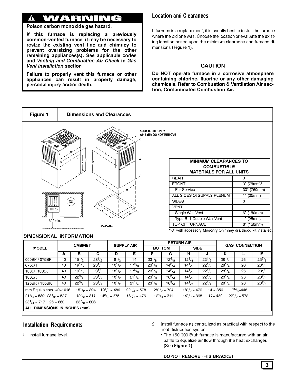
Locationand Clearances
Iffurnace is a replacement, it is usually best to install the furnace
where the old one was. Choose the location orevaluate the exist-
ing location based upon the minimum clearance and furnace di-
mensions (Figure 1).
CAUTION
Do NOT operate furnace in a corrosive atmosphere
containing chlorine, fluorine or any other damaging
chemicals. Refer to Combustion & Ventilation Air sec-
tion, Contaminated Combustion Air.
Figure 1 Dimensions and Clearances
150,000BTUONLY
AirBaffleDONOTREMOVE
L _ _ _
30i rain. 2s-2o-z_,
DIMENSIONAL INFORMATION
MINIMUM CLEARANCES TO
COMBUSTIBLE
MATERIALS FOR ALL UNITS
REAR 0
FRONT 3" (75mm)*
For Service 30" (760mm)
ALL SIDES Of SUPPLY PLENUM 1" (25mm)
SIDES 0
VENT
Single Wall Vent 6" (150mm)
Type B-1 Double Wall Vent 1" (25mm)
TOP OF FURNACE 6" (150mm)
* 6" with accessory Masonry Chimney drafthood kit installe,
RETURN AIR
CABINET SUPPLY AIR GAS CONNECTION
MODEL BOTTOM SIDE
A B C D E F G H J K L M
050BF / 075BF 40 151/2 281/2 181/2 14 231/8 125/8 121/4 221/2 281/4 26 237/8
075BH 40 191/8 281/2 181/2 175/8 231/8 143/4 141/2 221/2 281/4 26 237/8
100BF,100BJ 40 191/8 281/2 181/2 178/8 231/8 143/4 141/2 221/2 281/4 26 237/8
100BK 40 223/4 281/2 181/2 211/4 231/8 183/4 141/2 221/2 281/4 26 237/8
125BK / 150BK 40 223/4 281/2 181/2 211/4 231/8 183/4 141/2 221/2 281/4 26 237/8
mm Equivalents 40=10t6 151/2 = 394 191/8 = 486 228/4 = 578 281/2 = 724 181/2 = 470 14 = 356 178/8=448
211/4 = 539 231/8 = 587 128/8 = 311 143/4 = 375 183/4 = 476 121/4 = 311 141/2 = 368 t7= 432 221/2 = 572
281/4 = 717 26 = 660 237/8 = 606
ALL DIMENSIONS IN INCHES (ram)
Installation Requirements
1. Install furnace level.
Install furnace as centralized as practical with respect to the
heat distribution system
• The 150,000 Btuh furnace is manufactured with an air
baffle to equalize air flow through the heat exchanger.
(See Figure 1).
DO NOT REMOVE THIS BRACKET
3. Install the vent pipes as short as practical. (See Gas Vent
Installation section).
4. De NOT install furnace directly on carpeting, tile or other
combustible material other than wood flooring.
5. Maintain clearance for fire safety and servicing. A front clear-
ance of 30" (760mm) is minimum for access to the burner,
controls and filter.
6. Use a raised base if the floor is damp or wet at times.
7. Residential garage installations require:
• Burners and ignition sources installed at least 18" (457mm)
above the floor.
• Furnace must be located or physically protected from pos-
sible damage by a vehicle.
Horizontal Furnace Installation
IMPORTANT
NOTE: Inspect unit rating plate to be certain model number be-
gins with "NTC5, NTN5 or GNJ'. This identifies unit as horizon-
tally mountable. If unit does NOT bear this designation, you may
NOT mount this unit horizontally. Horizontal furnace may not be
mounted on its back.
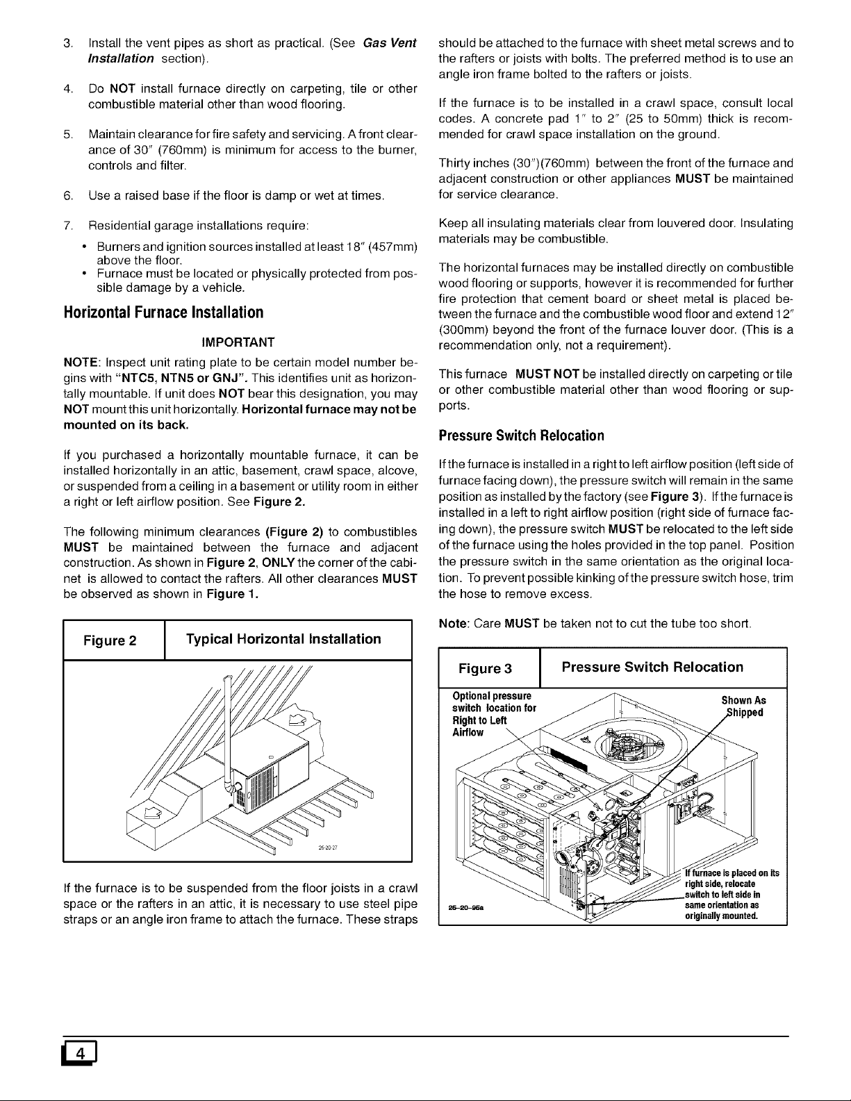
If you purchased a horizontally mountable furnace, it can be
installed horizontally in an attic, basement, crawl space, alcove,
or suspended from a ceiling in a basement or utility room in either
a right or left airflow position. See Figure 2.
The following minimum clearances (Figure 2) to combustibles
MUST be maintained between the furnace and adjacent
construction. As shown in Figure 2, ONLY the corner of the cabi-
net is allowed to contact the rafters. All other clearances MUST
be observed as shown in Figure 1.
Figure 2 Typical Horizontal Installation
If the furnace is to be suspended from the floor joists in a crawl
space or the rafters in an attic, it is necessary to use steel pipe
straps or an angle iron frame to attach the furnace. These straps
should be attached to the furnace with sheet metal screws and to
the rafters or joists with bolts. The preferred method is to use an
angle iron frame bolted to the rafters or joists.
If the furnace is to be installed in a crawl space, consult local
codes. A concrete pad 1" to 2" (25 to 50ram) thick is recom-
mended for crawl space installation on the ground.
Thirty inches (30")(760mm) between the front ofthe furnace and
adjacent construction or other appliances MUST be maintained
for service clearance.
Keep all insulating materials clear from Iouvered door. Insulating
materials may be combustible.
The horizontal furnaces may be installed directly on combustible
wood flooring or supports, however it is recommended for further
fire protection that cement board or sheet metal is placed be-
tween the furnace and the combustible wood floor and extend 12"
(300mm) beyond the front of the furnace louver door. (This is a
recommendation only, not a requirement).
This furnace MUST NOT be installed directly on carpeting or tile
or other combustible material other than wood flooring or sup-
ports.
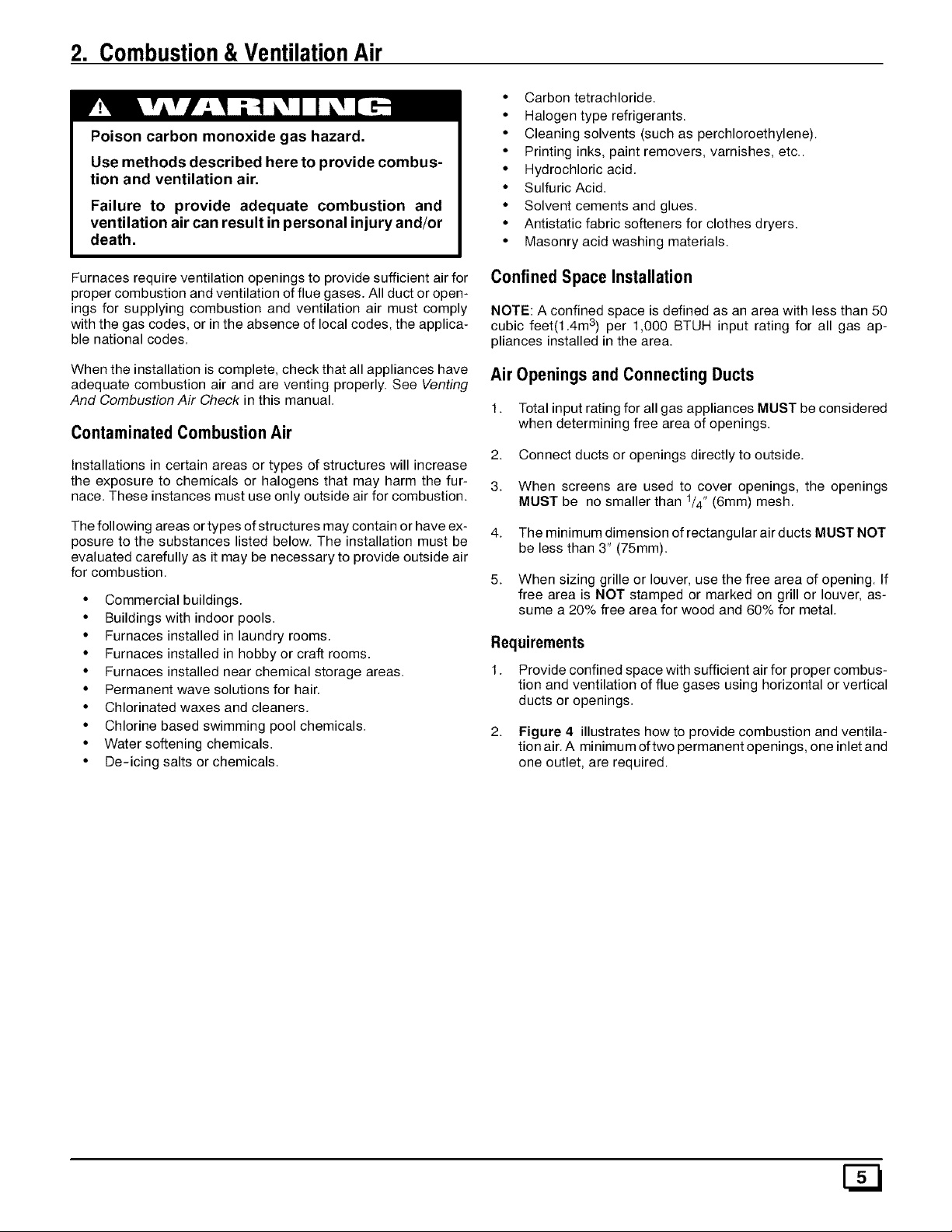
Pressure Switch Relocation
Ifthe furnace is installed in a right to left airflow position (left side of
furnace facing down), the pressure switch will remain inthe same
position as installed by the factory (see Figure 3). Ifthe furnace is
installed in a left to right airflow position (right side of furnace fac-
ing down), the pressure switch MUST be relocated to the left side
of the furnace using the holes provided inthe top panel. Position
the pressure switch in the same orientation as the original loca-
tion. To prevent possible kinking ofthe pressure switch hose, trim
the hose to remove excess.
Note: Care MUST be taken not to cut the tube too short.
Figure 3 Pressure Switch Relocation
Optionalpressure ShownAs
switchlocationfor
RighttoLeft
Airflow
rightside,relocate
switchto left sidein
sameorientationas
originallymounted,
2. Combustion&VentilationAir
Poison carbon monoxide gas hazard.
Use methods described here to provide combus-
tion and ventilation air.
Failure to provide adequate combustion and
ventilation air can result in personal injury and/or
death,
Furnaces require ventilation openings to provide sufficient air for
proper combustion and ventilation of flue gases. All duct or open-
ings for supplying combustion and ventilation air must comply
with the gas codes, or in the absence of local codes, the applica-
ble national codes.
When the installation is complete, check that all appliances have
adequate combustion air and are venting properly. See Venting
And Combustion Air Check in this manual.
ContaminatedCombustionAir
Installations in certain areas or types of structures will increase
the exposure to chemicals or halogens that may harm the fur-
nace. These instances must use only outside air for combustion.
The following areas or types of structures may contain or have ex-
posure to the substances listed below. The installation must be
evaluated carefully as it may be necessary to provide outside air
for combustion.
• Commercial buildings.
• Buildings with indoor pools.
• Furnaces installed in laundry rooms.
• Furnaces installed in hobby or craft rooms.
• Furnaces installed near chemical storage areas.
• Permanent wave solutions for hair.
• Chlorinated waxes and cleaners.
• Chlorine based swimming pool chemicals.
• Water softening chemicals.
• De-icing salts or chemicals.
• Carbon tetrachloride.
• Halogen type refrigerants.
• Cleaning solvents (such as perchloroethylene).
• Printing inks, paint removers, varnishes, etc..
• Hydrochloric acid.
• Sulfuric Acid.
• Solvent cements and glues.
• Antistatic fabric softeners for clothes dryers.
• Masonry acid washing materials.
Confined Space Installation
NOTE: A confined space is defined as an area with less than 50
cubic feet(1.4m s) per 1,000 BTUH input rating for all gas ap-
pliances installed in the area.
Air Openings and ConnectingDucts
1. Total input rating for all gas appliances MUST be considered
when determining free area of openings.
2. Connect ducts or openings directly to outside.
3. When screens are used to cover openings, the openings
MUST be no smaller than 1/4" (6mm) mesh.
4. The minimum dimension of rectangular air ducts MUST NOT
be less than 3" (75mm).
5. When sizing grille or louver, use the free area of opening. If
free area is NOT stamped or marked on grill or louver, as-
sume a 20% free area for wood and 60% for metal.
Requirements
1. Provide confined space with sufficient air for proper combus-
tion and ventilation of flue gases using horizontal or vertical
ducts or openings.
2. Figure 4 illustrates how to provide combustion and ventila-
tion air. A minimum oftwo permanent openings, one inlet and
one outlet, are required.
 Loading...