


FEM4P1800A1
ICP FEM4P1800A1, FEM4P1800AT1, FEM4P2400A1, FEM4P2400AT1, FEM4P3000A1 Installation Guide
...
These instructions must be read and understood completely before attempting installation.
Safety Labeling and Signal Words
DANGER, WARNING, CAUTION, and
NOTE
The signal words DANGER, WARNING,
CAUTION, and NOTE are used to identify levels of
hazard seriousness. The signal word DANGER is
only used on product labels to signify an immediate
hazard. The signal words WARNING, CAUTION,
and NOTE will be used on product labels and
throughout this manual and other manuals that may
apply to the product.
DANGER - Immediate hazards which will result in
severe personal injury or death.
WARNING - Hazards or unsafe practices which
could result in severe personal injury or death.
CAUTION - Hazards or unsafe practices which
may result in minor personal injury or product or
property damage.
NOTE - Used to highlight suggestions which will
result in enhanced installation, reliability, or
operation.
Signal Words in Manuals
The signal word WARNING is used throughout this
manual in the following manner:
The signal word CAUTION is used throughout this
manual in the following manner:
Signal Words on Product Labeling
Signal words are used in combination with colors
and/or pictures on product labels.
TABLE OF CONTENTS
Introduction .................................... 2
Location ....................................... 2
Clearances and Dimensions ................... 3-4
Heater Packages ............................... 5
Position Unit ................................. 5-9
Air Ducts ..................................... 10
Electrical Connections ...................... 10-14
Refrigerant Tubing ............................. 15
Refrigerant Flow-Control Device ................ 15
Condensate Drains ............................ 16
Accessories .................................. 17
Sequence of Operation ......................... 18
Start-up Procedure ............................ 18
Care and Maintenance ......................... 18
Airflow Performance ........................ 19-20
R-410A Quick Reference Guide ................. 21
PERSONAL INJURY, AND/OR PROPERTY DAM-
AGE HAZARD
Failure to carefully read and follow this warning
could result in equipment malfunction, property
damage, personal injury and/or death.
Installation or repairs made by unqualified per-
sons could result in equipment malfunction, prop-
erty damage, personal injury and/or death.
The information contained in this manual is in-
tended for use by a qualified service technician fa-
miliar with safety procedures and equipped with
the proper tools and test instruments.
Installation must conform with local building
codes and with the National Electrical Code
NFPA70 current edition.
496 01 5501 01 April 2011
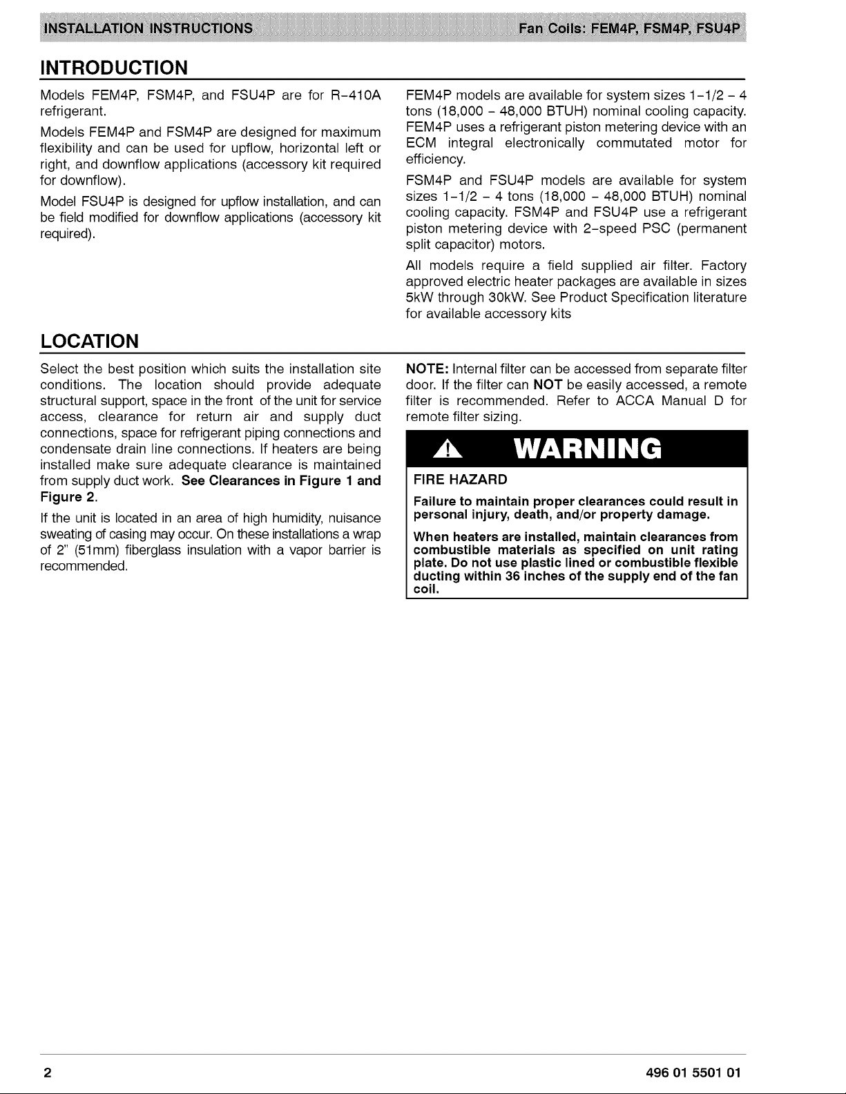
INTRODUCTION
Models FEM4P, FSM4P, and FSU4P are for R-410A
refrigerant.
Models FEM4P and FSM4P are designed for maximum
flexibility and can be used for upflow, horizontal left or
right, and downflow applications (accessory kit required
for downflow).
Model FSU4P is designed for upflow installation, and can
be field modified for downflow applications (accessory kit
required).
LOCATION
Select the best position which suits the installation site
conditions. The location should provide adequate
structural support, space in the front of the unit for service
access, clearance for return air and supply duct
connections, space for refrigerant piping connections and
condensate drain line connections. If heaters are being
installed make sure adequate clearance is maintained
from supply duct work. See Clearances in Figure 1 and
Figure 2.
If the unit is located in an area of high humidity, nuisance
sweating of casing may occur. On these installations a wrap
of 2" (51mm) fiberglass insulation with a vapor barrier is
recommended.
FEM4P models are available for system sizes 1-1/2 - 4
tons (18,000 - 48,000 BTUH) nominal cooling capacity.
FEM4P uses a refrigerant piston metering device with an
ECM integral electronically commutated motor for
efficiency.
FSM4P and FSU4P models are available for system
sizes 1-1/2 - 4 tons (18,000 - 48,000 BTUH) nominal
cooling capacity. FSM4P and FSU4P use a refrigerant
piston metering device with 2-speed PSC (permanent
split capacitor) motors.
All models require a field supplied air filter. Factory
approved electric heater packages are available in sizes
5kW through 30kW. See Product Specification literature
for available accessory kits
NOTE: Internal filter can be accessed from separate filter
door. If the filter can NOT be easily accessed, a remote
filter is recommended. Refer to ACCA Manual D for
remote filter sizing.
FIRE HAZARD
Failure to maintain proper clearances could result in
personal injury, death, and/or property damage.
When heaters are installed, maintain clearances from
combustible materials as specified on unit rating
plate. Do not use plastic lined or combustible flexible
ducting within 36 inches of the supply end of the fan
coil.
2 496 01 5501 01
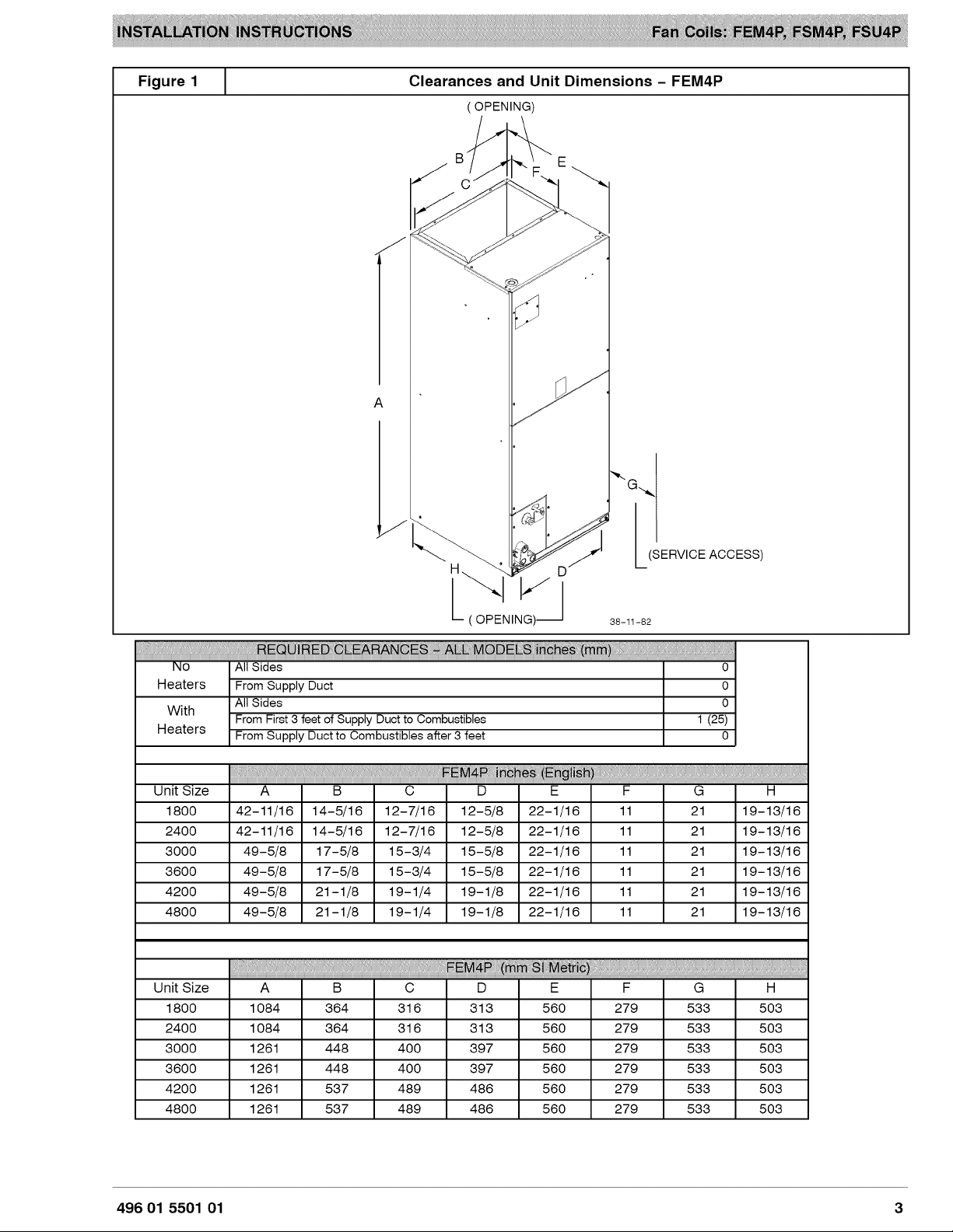
Figure1 [
ClearancesandUnitDimensions- FEM4P
(OPENING)
B
C
A
_" GJ(SERVICE ACCESS)
i ("(_OPENING)_G_.
38-11-82
! !!
No All Sides 0
Heaters From Supply Duct 0
With
Heaters
All Sides 0
From First 3 feet of Supply Duct to Combustibles 1 (25)
From Supply Duct to Combustibles after 3 feet 0
M !!!!!
Unit Size A B C D E F G H
1800 42-11/16 14-5/16 12-7/16 12-5/8 22-1/16 11 21 19-13/16
2400 42-11/16 14-5/16 12-7/16 12-5/8 22-1/16 11 21 19-13/16
3000 49-5/8 17-5/8 15-3/4 15-5/8 22-1/16 11 21 19-13/16
3600 49-5/8 17-5/8 15-3/4 15-5/8 22-1/16 11 21 19-13/16
4200 49-5/8 21-1/8 19-1/4 19-1/8 22-1/16 11 21 19-13/16
4800 49-5/8 21-1/8 19-1/4 19-1/8 22-1/16 11 21 19-13/16
Unit Size A B C D E F G H
1800 1084 364 316 313 560 279 533 503
2400 1084 364 316 313 560 279 533 503
3000 1261 448 400 397 560 279 533 503
3600 1261 448 400 397 560 279 533 503
4200 1261 537 489 486 560 279 533 503
4800 1261 537 489 486 560 279 533 503
496 01 5501 01 3
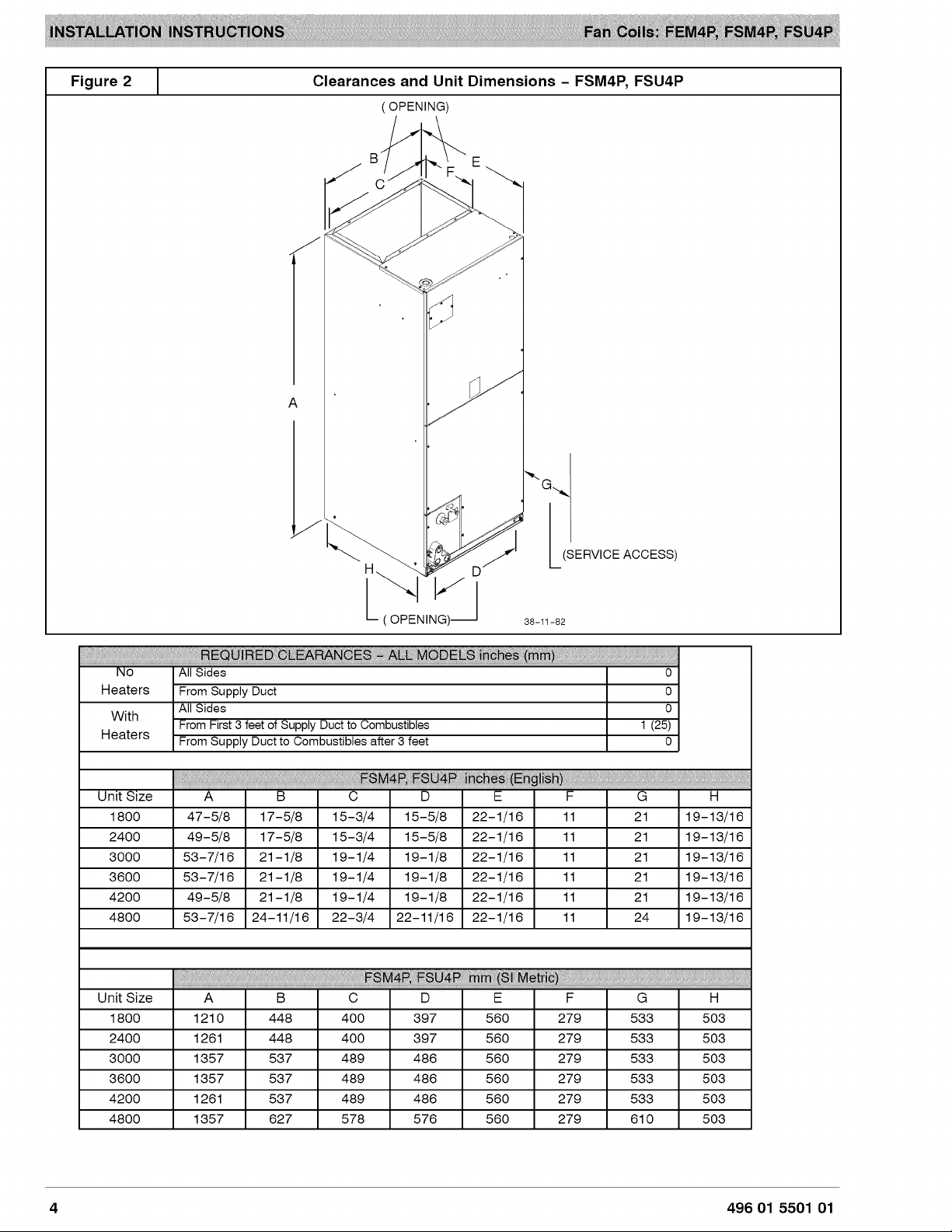
Figure
2 J ClearancesandUnitDimensions- FSM4P,FSU4P
OPENING)
A
J
_" GJ-__SERVICE ACCESS)
38-11-82
!!!!!!!!!!!!!_!_!_!!!!!i!!_!!_!!_!!_!!_!!_!!_!!_!!_!!_!!_!!_!!_!!_!!_!!_!!_!!_!!_!!_!_!_!_!_!:_!b!!!_!_@N!_!_!!!!!_!!_!!_!_!!!__!_!i_!!!!!i!!!_!!
No All Sides 0
Heaters From Supply Duct 0
With
Heaters
All Sides 0
From First 3 feet of Supply Duct to Combustibles 1 (25)
From Supply Duct to Combustibles after 3 feet 0
_ _!_!_! _ !!_!!!!!!!!!!!!!!!!!!!!!!!!!!!!!!!!!!!!!!!!!!!!!!!!!!!!!!!!!!!!!!!!!!!!!!!!!!!!!!!!!!!!!!!!!!!!!!!!!!!!!!!!!!!!!!!!!!!!!!!!!!!!!!!!!!!!!!!!!!!!!!!!!!!!!
Unit Size A B C D E F G H
1800 47-5/8 17-5/8 15-3/4 15-5/8 22-1/16 11 21 19-13/16
2400 49-5/8 17-5/8 15-3/4 15-5/8 22-1/16 11 21 19-13/16
3000 53-7/16 21-1/8 19-1/4 19-1/8 22-1/16 11 21 19-13/16
3600 53-7/16 21-1/8 19-1/4 19-1/8 22-1/16 11 21 19-13/16
4200 49-5/8 21-1/8 19-1/4 19-1/8 22-1/16 11 21 19-13/16
4800 53-7/16 24-11/16 22-3/4 22-11/16 22-1/16 11 24 19-13/16
!!!!!!!!!!!_!_!i!!!!i!_ __i!:!!!_!i_!_!!!!!!!!!!_!!!!!!_i_ !!!!i!!!!i!!!!i!!
Unit Size A B C D E F G H
1800 1210 448 400 397 560 279 533 503
2400 1261 448 400 397 560 279 533 503
3000 1357 537 489 486 560 279 533 503
3600 1357 537 489 486 560 279 533 503
4200 1261 537 489 486 560 279 533 503
4800 1357 627 578 576 560 279 610 503
4 496 01 5501 01
HEATER PACKAG ES
Factory approved, field installed, UL listed heater
packages are available from the equipment supplier. See
unit rating plate for a list of factory approved heaters.
POSITION UNIT
Unit can stand or lie on floor, or hang from ceiling or wall.
Allow space for wiring, piping, and servicing unit.
PROPERTY DAMAGE HAZARD
Failure to follow this caution may result in proper-
ty damage
A field fabricated auxiliary drain pan, with a sepa-
rate drain is REQUIRED for all installations over a
finished living space or in any area that may be
damaged by overflow from a restricted main drain
pan. In some localities, local codes require an aux-
iliary drain pan for ANY horizontal installation.
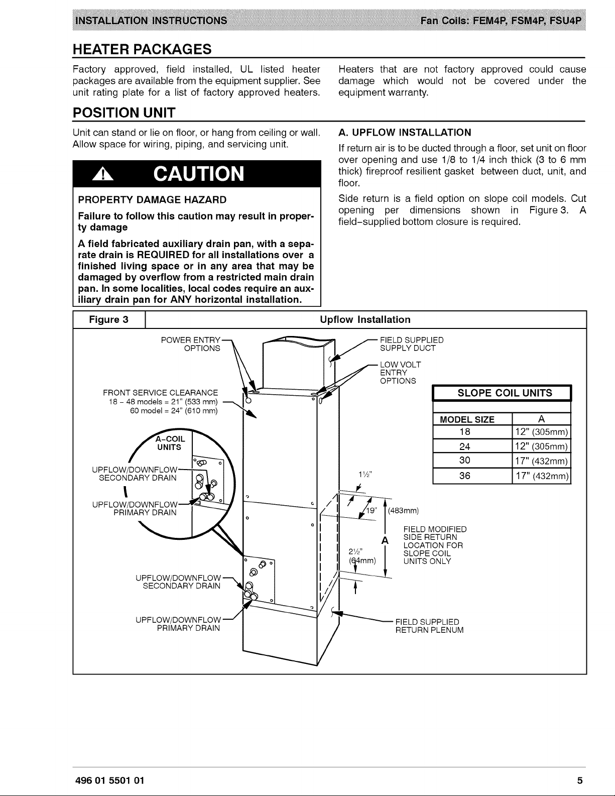
Figure 3 [
POWER
OPTIONS
FRONT SERVICE CLEARANCE
18 - 48 models = 21" (533 mm)
60 model = 24" (610 mm)
UPFLOW/_
Heaters that are not factory approved could cause
damage which would not be covered under the
equipment warranty.
A. UPFLOW INSTALLATION
If return air is to be ducted through a floor, set unit on floor
over opening and use 1/8 to 1/4 inch thick (3 to 6 mm
thick) fireproof resilient gasket between duct, unit, and
floor.
Side return is a field option on slope coil models. Cut
opening per dimensions shown in Figure 3. A
field-supplied bottom closure is required.
Upflow Installation
S SUPPLY DUCT
LOW VO LT
tl ENTRY
OPTIONS
FIELD SUPPLIED
11/2"
SLOPE COIL UNITS
MODEL SIZE A
18 12" (305mm)
24 12" (305mm)
30 17" (432mm)
36 17" (432mm)
)
SECONDARY DRAIN
/4 -
( 483mm)
II _ SIDE RETURN
2W'
IlL _4mm) [ UNITS ONLY
FIELD MODIFIED
LOCATION FOR
SLOPE COIL
/
PRIMARY DRAIN
FIELD SUPPLIED
RETURN PLENUM
/
496 01 5501 01 5
B.DOWNFLOWINSTALLATION
PRODUCT OR PROPERTY DAMAGE HAZARD
Failure to follow this caution may result in product
or property damage
The conversion of the fan coil to downflow re-
quires special procedures for the condensate
drains on both A-coil and Slope-coil units. The
vertical drains have an overflow hole between the
primary and secondary drain holes. This hole is
plugged for all applications except downflow, and
must be used for downflow.
Failure to follow instructions could result in per-
sonal injury or product and property damage.
In this application, field conversion of the evaporator coil
is required using accessory Downflow Kit along with an
accessory Base Kit. Set unit on floor over opening and
use 1/8" to 1/4" thick fireproof resilient gasket between
duct, unit, and floor. Refer to installation instructions
packaged with accessory kit. See Product Specification
literature for kit part numbers.
During the conversion process, removed the plastic cap
covering the vertical drains only and discard.
Remove the plug from the overflow hole and discard.
At completion of the downflow installation, caulk around
the vertical pan fitting to door joint to retain low air leak
performance of the unit.
NOTE: Gasket kit number (EBACO1GSK) is also
required for all downflow applications to maintain low air
leak/low sweat performance.
C. HORIZONTAL INSTALLATION
Unit must NOT be installed with access panels facing up
or down. Access panels must only face to the side.
FEM4P and FSM4P models are factory built for
horizontal left installation (refer to Figure 4 and Figure 5).
They can be field converted to horizontal right (accessory
Gasket Kit required, see Product Specification literature
for part number). Refer to Figure 6 and Figure 7.
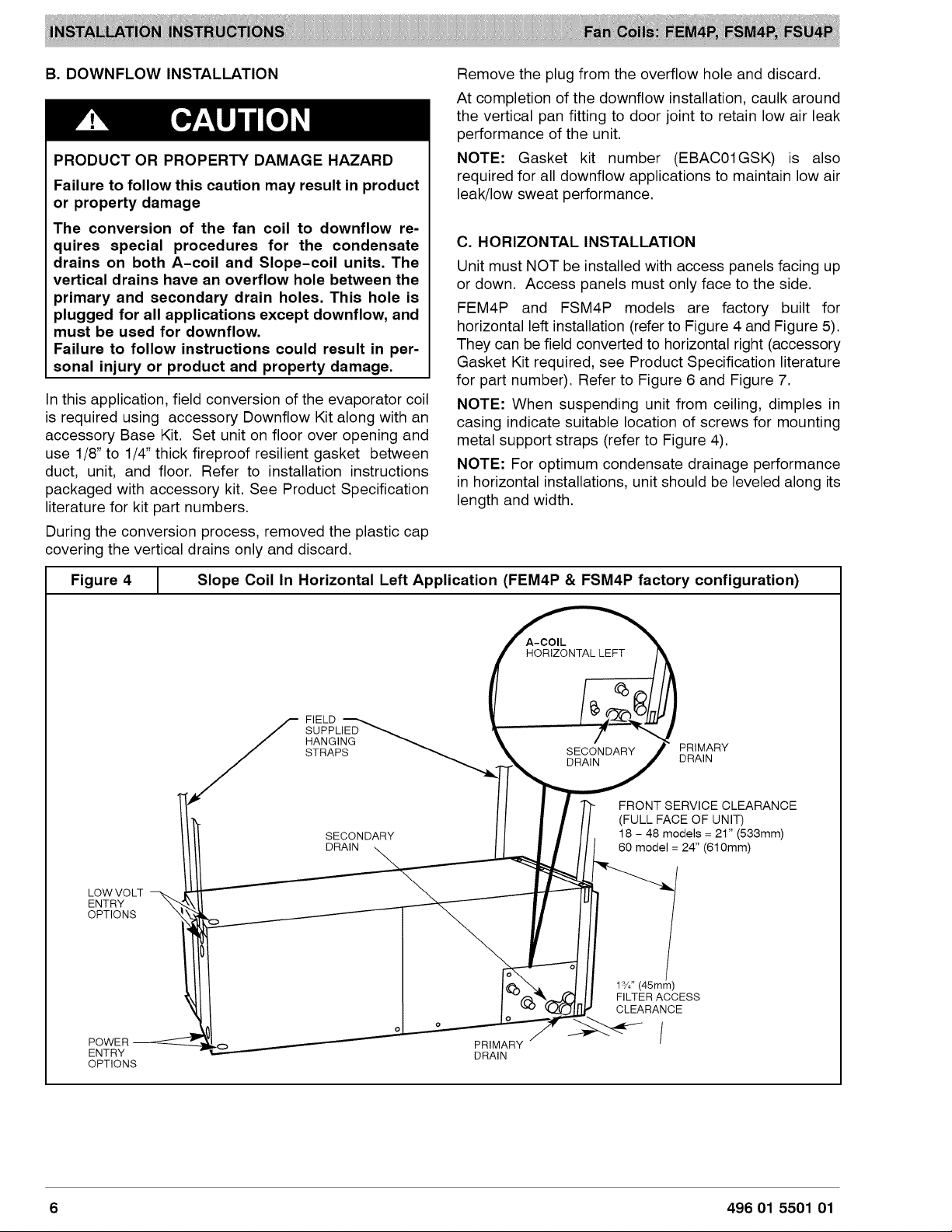
NOTE: When suspending unit from ceiling, dimples in
casing indicate suitable location of screws for mounting
metal support straps (refer to Figure 4).
NOTE: For optimum condensate drainage performance
in horizontal installations, unit should be leveled along its
length and width.
Figure 4 J Slope Coil In Horizontal Left Application (FEM4P & FSM4P factory configuration)
A-COIL
HORIZONTAL LEFT
FIELD
SUPPLIED
LOW VOLT
ENTRY
OPTIONS
HANGING
STRAPS
SECONDARY
DRAIN
SECONDARY PRIMARY
DRAIN DRAIN
FRONT SERVICE CLEARANCE
(FULL FACE OF UNIT)
18 - 48 models = 21" (533mm)
60 model = 24" (610mm)
1¾"(45mm)
FILTER ACCESS
CLEARANCE
POWER
ENTRY
OPTIONS
PRIMARY
DRAIN
6 496 01 5501 01
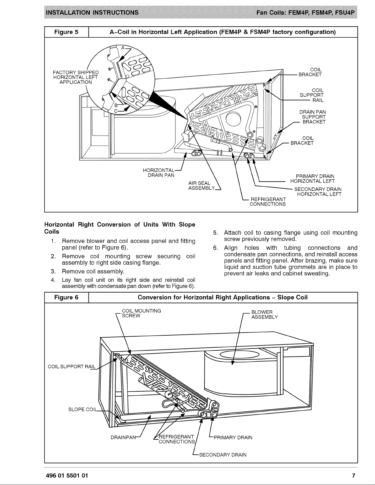
Figure5 [ A-Coil in HorizontalLeftApplication(FEM4P& FSM4Pfactoryconfiguration)
FACTORY SHIPPED
HORIZONTAL LEFT
APPLICATION
HORIZONTAL.
DRAIN PAN
AIR SEAL
Horizontal Right Conversion of Units With Slope
Coils 5.
1.
Remove blower and coil access panel and fitting
panel (refer to Figure 6).
2.
Remove coil mounting screw securing coil
assembly to right side casing flange.
3.
Remove coil assembly.
4.
Lay fan coil unit on its right side and reinstall coil
assembly with condensate pan down (refertoFigure 6).
-- BRACKET
BRACKET
HORIZONTAL LEFT
REFRIGERANT
CONNECTIONS
COIL
COIL
SUPPORT
RAI L
DRAIN PAN
SUPPORT
BRACKET
COIL
PRIMARY DRAIN
SECONDARY DRAIN
HORIZONTALLEFT
Attach coil to casing flange using coil mounting
screw previously removed.
6.
Align holes with tubing connections and
condensate pan connections, and reinstall access
panels and fitting panel. After brazing, make sure
liquid and suction tube grommets are in place to
prevent air leaks and cabinet sweating.
Figure 6 [ Conversion for Horizontal Right Applications - Slope Coil
COIL MOUNTING
COIL SUPPORT RAIL
SLOPE
:{EFRIGERANT
CONNECTIONS
SECONDARY DRAIN
496 01 5501 01 7
BLOWER
ASSEMBLY
DRAIN
 Loading...