


INSTALLATION INSTRUCTIONS Cased N Coil, Upflow−Downflow
END4X, ENW4X
NOTE: Read the entire instruction manual before starting the installation.
SAFETY CONSIDERATIONS
Improper installation, adjustment, alteration, service, maintenance, or use can cause explosion, fire, electrical shock, or other conditions which may cause death, personal injury or property damage. Consult a qualified installer, service agency, or your distributor or branch for information or assistance. The qualified installer or agency must use factory−authorized kits or accessories when modifying this product. Refer to the individual instructions packaged with the kits or accessories when installing.
Follow all safety codes. Wear safety glasses, protective clothing, and work gloves. Use quenching cloth for brazing operations. Have fire extinguisher available. Read these instructions thoroughly and follow all warning or cautions included in literature and attached to the unit. Consult local building codes and the current editions of the National Electrical Code (NEC) NFPA 70.
In Canada, refer to the current editions of the Canadian Electrical Code CSA C22.1.
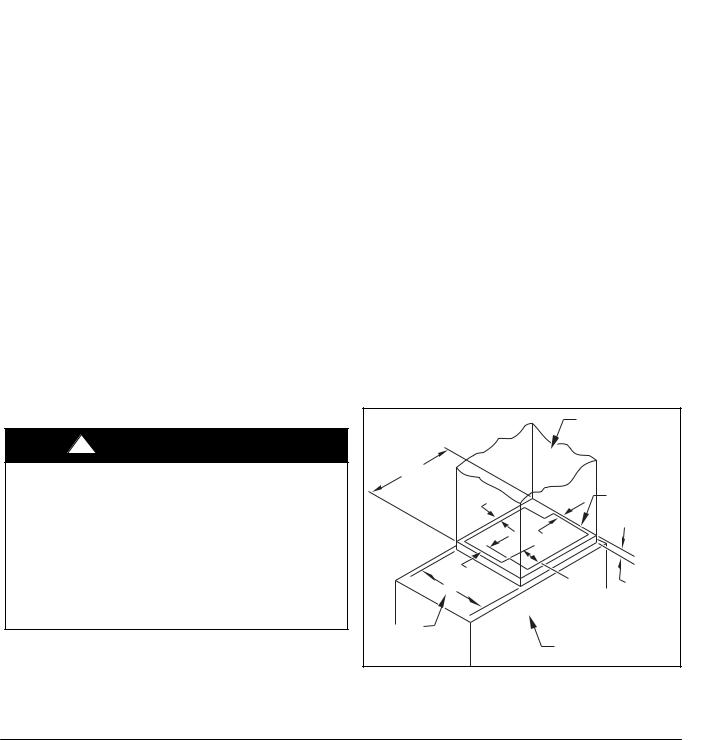
Recognize safety information. When you see this symbol  on
on
the unit and in instructions or manuals, be alert to the potential for personal injury. Understand the signal words DANGER, WARNING, CAUTION, and NOTE. These words are used with the safety−alert symbol. DANGER identifies the most serious hazards which will result in severe personal injury or death. WARNING signifies hazards which could result in personal injury or death. CAUTION is used to identify unsafe practices which may result in minor personal injury or product and property damage. NOTE is used to highlight suggestions which will result in enhanced installation, reliability, or operation.
IMPORTANT: Nitrogen can leak out through the hole that the needle pierced in the plugs. This does not indicate a leaking coil nor warrant return of the coil.
!WARNING
ELECTRICAL SHOCK HAZARD
Failure to follow this warning could result in personal injury or death.
Before installing, modifying or servicing system, always turn off main power to system. There may be more than one disconnect switch. Lock out and tag switch with a suitable warning label.
!CAUTION
PERSONAL INJURY HAZARD
Failure to follow this caution may result in personal injury.
This coil contains Nitrogen precharge of 15 PSIG. Release of this pressure through the center of the rubber plugs is required before removing the plugs.
!CAUTION
ENVIRONMENTAL HAZARD
Failure to follow this caution may result in environmental pollution.
Remove and recycle all components or materials (i.e. oil, refrigerant, etc.) before unit final disposal.
!CAUTION
CUT HAZARD
Failure to follow this caution may result in personal injury.
Sheet metal parts may have sharp edges or burrs. Use care and wear appropriate protective clothing and gloves when handling parts.
!CAUTION
UNIT OR PROPERTY DAMAGE HAZARD
Failure to follow this caution may result in property damage.
Take precautions to ensure Aluminum tubes do not come in direct contact or allow for condensate run off with a dissimilar metal. Dissimilar metals can cause galvanic corrosion and possible premature failure.
TABLE OF CONTENTS
PAGE
SAFETY CONSIDERATIONS . . . . . . . . . . . . . . . . . . . . . . . . . . . . 1
INTRODUCTION . . . . . . . . . . . . . . . . . . . . . . . . . . . . . . . . . . . . . . . 2
INSTALLATION . . . . . . . . . . . . . . . . . . . . . . . . . . . . . . . . . . . . . . . . 2
Airflow . . . . . . . . . . . . . . . . . . . . . . . . . . . . . . . . . . . . . . . . . . . . . . . 2
TXV . . . . . . . . . . . . . . . . . . . . . . . . . . . . . . . . . . . . . . . . . . . . . . . . . 2
Inspect Equipment . . . . . . . . . . . . . . . . . . . . . . . . . . . . . . . . . . . . 2
Select Installation Procedure . . . . . . . . . . . . . . . . . . . . . . . . . . . 2
Installation of Furnace Coils . . . . . . . . . . . . . . . . . . . . . . . . . . . . 3
Connect Refrigerant Piping . . . . . . . . . . . . . . . . . . . . . . . . . . . . . 5
Connect Refrigerant Liquid and Suction Lines . . . . . . . . . . . . . 5
Refrigerant Metering Device . . . . . . . . . . . . . . . . . . . . . . . . . . . . 5
Condensate Drain Line Connection . . . . . . . . . . . . . . . . . . . . . . 5
Waste Line Connection . . . . . . . . . . . . . . . . . . . . . . . . . . . . . . . . 6
Humidifier Application . . . . . . . . . . . . . . . . . . . . . . . . . . . . . . . . . . 6
INTRODUCTION
Use this instruction manual to install indoor coils on upflow or downflow furnaces. Do not install coil in horizontal position. Coils are enclosed in a painted casing have factory−installed TXV’s. These coils are used with R−410A refrigerant systems.
Specifications subject to change without notice.
484 01 3601 02 8/9/17
INSTALLATION
These units can be installed in multiple configurations. Before installation, there are several performance requirements that must be considered because poor installation can negatively alter performance. This section will briefly discuss those factors.
Airflow
Airflow amount and distribution are vital to adequate system performance. Problems that can be experienced with incorrect airflow include:
Slow system performance
Srestricted TXV
Sfrosted coil
Spoor humidity control
S water blow−off
When attaching the coil and building the plenum, pay special attention to the effect these details will have on airflow. After system start−up, check the cfm to insure that it is correct. (Generally, the cfm should be 350 to 400 cfm/ton during normal cooling operation.)
Cabinet Sweating
If this unit is installed in a garage, attic, or other unconditioned space, special attention needs to be given to the potential of cabinet sweating. A 6−in (152 mm) wide piece of insulation should be wrapped around the coil casing and supply duct connection point.
Inspect Equipment
File claim with shipper if equipment is damaged.
Table 1 |
|
|
|
END4X, ENW4X COIL INFORMATION |
|
|
||
|
|
FLUSH FIT TO |
COIL CONNECTION |
SHELF WIDTH |
FITS NEXT SMALLER FURNACE |
|||
|
|
TUBE SIZE |
(See Figure 1, |
|
|
|
||
MODEL NUMBER |
TONS |
FURNACE WIDTH |
Equal |
Overhang with |
|
|||
inches (mm) |
Dim. A) |
|
||||||
|
|
inches (mm) |
Offset Left |
|||||
|
|
|
|
Overhang |
Transition |
|||
|
|
Liquid |
Suction |
inches (mm) |
||||
|
|
|
|
|||||
|
|
|
|
|
|
|||
END4X18L14A |
1-1/2 |
14-3/16 (360) |
3/8 |
5/8 |
12-7/8 (327) |
N/A |
N/A |
N/A |
END4X19L17A |
1-1/2 |
17-1/2 (445) |
3/8 |
5/8 |
16-3/16 (411) |
No |
Yes |
Yes |
END4X24L14A |
2 |
14-3/16 (360) |
3/8 |
5/8 |
12-7/8 (327) |
N/A |
N/A |
N/A |
END4X24L17A |
2 |
17-1/2 (445) |
3/8 |
5/8 |
16-3/16 (411) |
No |
Yes |
Yes |
END4X30L14A |
2-1/2 |
14-3/16 (360) |
3/8 |
3/4 |
12-7/8 (327) |
N/A |
N/A |
N/A |
END4X30L17A |
2-1/2 |
17-1/2 (445) |
3/8 |
3/4 |
16-3/16 (411) |
No |
Yes |
Yes |
END4X31L17A |
2-1/2 |
17-1/2 (445) |
3/8 |
3/4 |
16-3/16 (411) |
No |
Yes |
Yes |
END4X36L17A |
3 |
17-1/2 (445) |
3/8 |
3/4 |
16-3/16 (411) |
No |
Yes |
Yes |
END4X36L21A |
3 |
21 (533) |
3/8 |
3/4 |
19-5/8 (498) |
No |
Yes |
Yes |
END4X37L17A |
3 |
17-1/2 (445) |
3/8 |
3/4 |
16-3/16 (411) |
Yes |
No |
No |
END4X42L17A |
3-1/2 |
17-1/2 (445) |
3/8 |
7/8 |
16-3/16 (411) |
No |
Yes |
Yes |
END4X42L21A |
3-1/2 |
21 (533) |
3/8 |
7/8 |
19-5/8 (498) |
No |
Yes |
Yes |
END4X43L24A |
3-1/2 |
24-1/2 (622) |
3/8 |
7/8 |
23-1/8 (587) |
No |
Yes |
Yes |
END4X48L21A |
4 |
21 (533) |
3/8 |
7/8 |
19-5/8 (498) |
No |
Yes |
Yes |
END4X48L24A |
4 |
24-1/2 (622) |
3/8 |
7/8 |
23-1/8 (587) |
No |
Yes |
Yes |
END4X60L24A |
5 |
24-1/2 (622) |
3/8 |
7/8 |
23-1/8 (587) |
No |
Yes |
Yes |
END4X61L24A |
5 |
24-1/2 (622) |
3/8 |
7/8 |
23-1/8 (587) |
No |
Yes |
No |
|
|
|
|
|
|
|
|
|
|
|
|
|
|
|
|
|
|
ENW4X36L17A |
3 |
17-1/2 (445) |
3/8 |
3/4 |
16-3/16 (411) |
Yes |
No |
No |
ENW4X42L21A |
3-1/2 |
21 (533) |
3/8 |
7/8 |
19-5/8 (498) |
Yes |
No |
No |
ENW4X48L21A |
4 |
21 (533) |
3/8 |
7/8 |
19-5/8 (498) |
Yes |
No |
No |
ENW4X60L24A |
5 |
24-1/2 (622) |
3/8 |
7/8 |
23-1/8 (587) |
Yes |
No |
No |
Select Installation Procedure
!CAUTION
PROPERTY DAMAGE HAZARD
Failure to follow this caution may result in property damage.
Installing coils rotated 90_ from the front of the furnace, in upflow or downflow applications, may cause water blow−off or coil freeze−up due to the concentration of air on one slab of the coil or lack of air to a slab in the coil. It is recommended that on this type of application, a field−supplied adapter be placed between the coil and furnace to allow air to distribute properly between all slabs of the coil.
See Table 1 for dimensions and overhang options. Refer to instructions for placement of coil casing on furnace.
|
Field-supplied |
|||
|
Plenum |
|
|
|
19 3⁄16″ |
|
|
|
|
(487) |
|
|
|
|
1⁄2″ |
|
Field |
|
|
(13) |
|
Coil |
|
|
|
|
Support Shelf |
||
|
1 1⁄16″ |
|
|
|
|
(27) |
|
|
|
1 3⁄16″ |
6″ |
|
|
|
A (30) |
2 |
1 |
⁄4″ |
|
(152) |
|
|||
|
|
(57) |
||
See |
|
|
|
|
Table 1 |
Furnace |
|
|
|
|
|
|
|
|
|
|
|
|
A08336 |
Figure 1 − Correct Orientation of Coil Support on Furnace
2 |
Specifications subject to change without notice. |
484 01 3601 02 |
 Loading...