


PYMC60G5
ICP PYMC60G5, PYMC48G5, PYMC48G1, PYMC42G5, PYMC42G1 Owner’s Manual
...
• Safety Labeling and Rules • Ductwork Connections
• Installation Requirements • Wiring
• Location/Clearances • Start-Up Procedures
• Air Distribution • Maintenance
• Economizer Accessory • Hoisting/Rigging
80-10-41
I RESIDENTIAL SINGLE PHASE WITH DIRECT DRIVE BLOWER II
Printed in U.S.A. 518 01 1001 00 7/97
I-
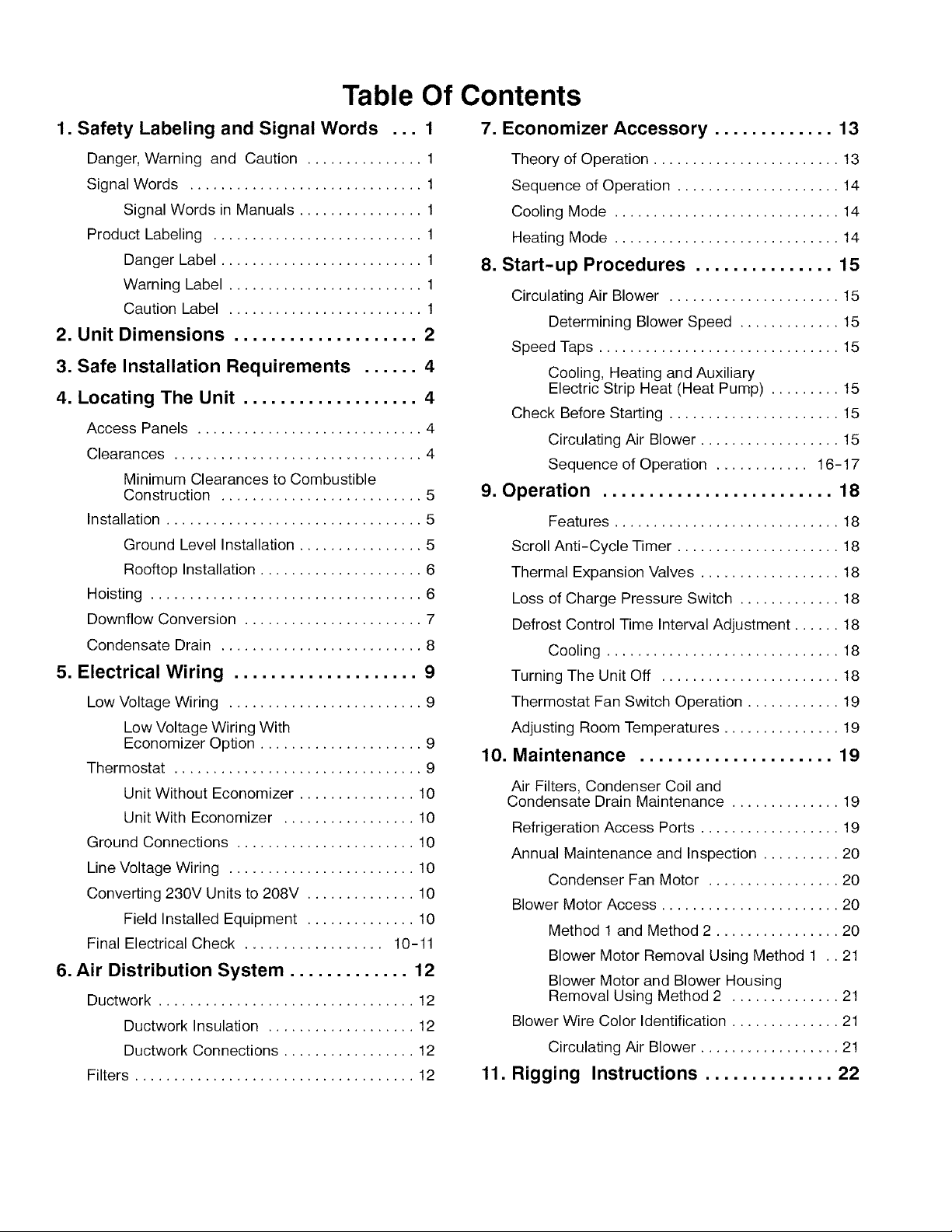
Table Of Contents
1. Safety Labeling and Signal Words ... 1
Danger, Warning and Caution ............... 1
Signal Words .............................. 1
Signal Words in Manuals ................ 1
Product Labeling ........................... 1
Danger Label .......................... 1
Warning Label ......................... 1
Caution Label ......................... 1
2. Unit Dimensions .................... 2
3. Safe Installation Requirements ...... 4
4. Locating The Unit ................... 4
Access Panels ............................. 4
Clearances ................................ 4
Minimum Clearances to Combustible
Construction .......................... 5
Installation ................................. 5
Ground Level Installation ................ 5
Rooftop Installation ..................... 6
Hoisting ................................... 6
Downflow Conversion ....................... 7
Condensate Drain .......................... 8
5. Electrical Wiring .................... 9
Low Voltage Wiring ......................... 9
Low Voltage Wiring With
Economizer Option ..................... 9
Thermostat ................................ 9
Unit Without Economizer ............... 10
Unit With Economizer ................. 10
Ground Connections ....................... 10
Line Voltage Wiring ........................ 10
Converting 230V Units to 208V .............. 10
Field Installed Equipment .............. 10
Final Electrical Check .................. 10-11
6. Air Distribution System ............. 12
Ductwork ................................. 12
Ductwork Insulation ................... 12
Ductwork Connections ................. 12
Filters .................................... 12
7. Economizer Accessory ............. 13
Theory of Operation ........................ 13
Sequence of Operation ..................... 14
Cooling Mode ............................. 14
Heating Mode ............................. 14
8. Start-up Procedures ............... 15
Circulating Air Blower ...................... 15
Determining Blower Speed ............. 15
Speed Taps ............................... 15
Cooling, Heating and Auxiliary
Electric Strip Heat (Heat Pump) ......... 15
Check Before Starting ...................... 15
Circulating Air Blower .................. 15
Sequence of Operation ............ 16-17
9. Operation ......................... 18
Features ............................. 18
Scroll Anti-Cycle Timer ..................... 18
Thermal Expansion Valves .................. 18
Loss of Charge Pressure Switch ............. 18
Defrost Control Time Interval Adjustment ...... 18
Cooling .............................. 18
Turning The Unit Off ....................... 18
Thermostat Fan Switch Operation ............ 19
Adjusting Room Temperatures ............... 19
10. Maintenance ..................... 19
Air Filters, Condenser Coil and
Condensate Drain Maintenance .............. 19
Refrigeration Access Ports .................. 19
Annual Maintenance and Inspection .......... 20
Condenser Fan Motor ................. 20
Blower Motor Access ....................... 20
Method 1and Method 2 ................ 20
Blower Motor Removal Using Method 1 .. 21
Blower Motor and Blower Housing
Removal Using Method 2 .............. 21
Blower Wire Color Identification .............. 21
Circulating Air Blower .................. 21
11. Rigging Instructions .............. 22

I Single Package Heat Pumps Installation Instructions I
1.SafetyLabeling andSignalWords
Danger,Warning and Caution
The signal wordsDANGER, WARNING and CAUTION are
used to identify levels of hazard seriousness. The signal
word DANGER is only used on product labels to signify an
immediate hazard. The signal words WARNING and CAU-
TION will be used on product labels and throughout this
manual and other manuals that may apply to the product.
Signal Words
DANGER - Immediate hazards which WILL result in se-
vere personal injury or death.
WARNING - Hazards or unsafe practices which COULD
result in severe personal injury or death.
CAUTION - Hazards or unsafe practices which COULD
result in minor personal injury or product or property dam-
age.
Danger Label
White lettering on a black background except the word
DANGER which is white with a red background.
Warning Label
White lettering on a black background except the word
WARNING which is black with an orange background.
Signal Words in Manuals
The signal word WARNING is used throughout this manual
in the following manner:
The signal word CAUTION is used throughout this manual
in the following manner:
CAUTION
Product Labeling
Signal words are used in combination with colors and/or
pictures on product labels. Following are examples of prod-
uct labels with explanations of the colors used.
Caution Label
White lettering on a black background except the word
CAUTION which is black with a yellow background.
12J
_ Installation Instructions Single Package Heat Pumps I
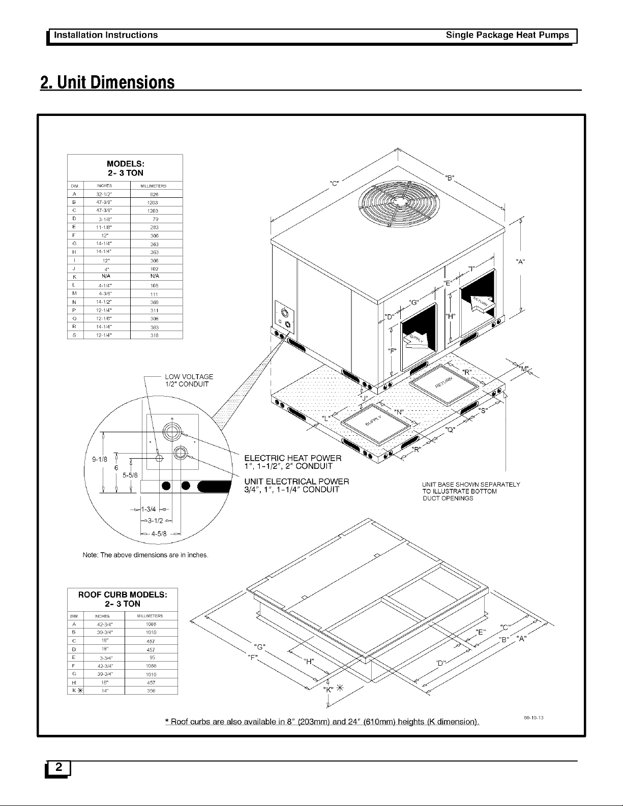
2. UnitDimensions
MODELS:
2- 3 TON
DIM INCHES MILLMETERS
A 32 1/2" 826
B 47 3/8" / 203
C 47 38" /203
D 3 1'8" 79
E /1 //8" 283
F 12" 306
G /4 1_4" 363
H /4 I/4" 363
I /2" 306
J 4" 102
K N/A N/A
L 4 /'4" /08
M 43/8" ///
N /4 //2" 368
P /2 /'4" 3/1
Q /2 1'8" 308
R E4 /4" 363
S /2 /'4" 3E8
LOW VOLTAGE
1/2" CONDUIT
Note: The above dimensions are in inches.
ROOF CURB MODELS:
2- 3 TON
DIM INOHES MILLIMETERS
A 42 34" /086
B 39 34" /0/0
C /8'r 457
D /8" 457
E 3 3_a" 95
F 42 34" / 086
G 39 3_a" /OE0
H E8" 457
K _ 14" 356
ELECTRIC HEAT POWER
1", 1-1/2", 2" CONDUIT
UNIT ELECTRICAL POWER
3/4", 1 ", 1-1/4" CONDUIT
"F'"
UNIT BASE SHOWN SEPARATELY
TO ILLUSTRATE BOTTOM
DUCT OPENINGS
* Roof curbs are also available in 8" (203mm) and 24" (610mm) heights (K dimension).
8_/_/3
I Single Package Heat Pumps Installation Instructions
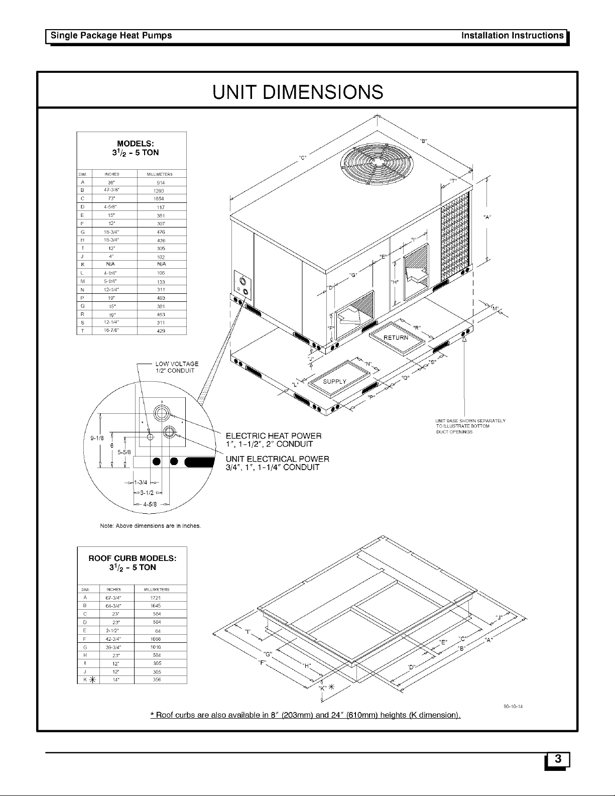
UNIT DIMENSIONS
MODELS:
31/2 - 5 TON
DIM INCHES MI L METERS
A 36" 9/4
B 47 38" / 203
C 73" /854
D 4 58" //7
E 15" 38I
F 12" 307
G /8 3/4" 476
H /8 3_4" 476
J E2" 305
J /02
K N/A
L 4 I '4" / 08
M 5 F4" E33
N 12 F4" 311
P E9" 483
Q 15" 381
R 19" 483
S /2 //4" 3/1
• /6 78" 429
I
I
I
Note: Above dimensions are in inches
ROOF CURB MODELS:
31/2 - 5 TON
DIM INCHES
A 67 3;4rr
B 64 3;4rr
C 23"
D 23"
E 2 //2"
F 42 3;4"
G 39 3t_4rr
H 23"
I /2"
J 12"
K _ /4"
f_'ILLIMETERS
/721
1645
1086
/010
LOW VOLTAGE
1/2" CONDUIT
584
584
64
584
305
305
356
ELECTRIC HEAT POWER
1", 1-1/2", 2" CONDUIT
UNIT ELECTRICAL POWER
3/4", 1", 1-1/4" CONDUIT
,,p.
UNIT BASE SHOWN SEPARATELY
TO _LLUSTRATE BOTTOM
DUCT OPENINGS
* Roof curbs are also available in 8" (203mm) and 24" (610mm) heights (K dimension).
80 /0 /4

_ Installation Instructions Single Package Heat Pumps I
3.SafeInstallationRequirements
• Seal supply and return air ducts.
Installation or repairs made by unqualified per-
sons can result in hazards to you and others.
Installation MUST conform with local building
codes or, in the absence of local codes, with the
National Electrical Code NFPA70-1990 or current
edition or in Canada CSA C22.1 - Canadian Elec-
trical Code Part 1 or current edition.
The information contained in this manual is in-
tended for use by a qualified service technician
familiar with safety procedures and equipped
with the proper tools and test instruments.
Failure to carefully read and follow all instruc-
tions in this manual can result in unit malfunction,
property damage, personal injury and/or death.
4. Locating TheUnit
The unit is designed for outdoor installation only. The unit
may be installed on a concrete slab (or other adequate plat-
form) at ground level, oron a rooftop with an adequate plat-
form or a roof curb. Typical installations are shown in
FIGURE 3 through FIGURE 5.
• Check to see that filters are installed correctly and
are the proper type and size.
NOTE: It is the personal responsibility and obligation of the
customer to contact a qualified installer to ensure that the
installation is adequate and conforms to governing codes
and ordinances.
Access Panels
CAUTION
Unit will NOT operate properly without all access pan-
els in place.
Unit MUST NOT be moved unless all access panels are
in place.
Avoid installations under roof overhangs without guttering.
Water draining from the roof onto the unit could produce ex-
cessive noise, and may cause ice to build up on coil or fan.
Roof top installations are acceptable providing the roof will
support the unit and provisions are made for water drain-
age and for the noise or vibration through the structure.
IJJ
See FIGURE 1 on page 5 for a general view of unit and
location of access panels.
Clearances
The location MUST allow for minimum clearances and
should not be adjacent to a patio or other area where the
unit's operating sound level might be objectionable. Local
codes MUST be observed.
Minimum clearances, as specified below and in FIGURE 2,
MUST be maintained from adjacent structures to provide
adequate air circulation and room for service personnel.

I Single Package Heat Pumps
While minimum clearances are acceptable for safety rea-
sons, they may not allow adequate air circulation around
the unit for proper operation. Whenever possible, it is desir-
able to allow additional clearance, especially around the
condenser inlet and discharge openings.
FIGURE1 _ Access Panels
Blower Access Panel
Installation Instructions
FIGURE 2 (Typical 2 to 3 ton unit shown)
(914mm) 0"
J 30" 30"
(762mm) (762mm)
Minimum Clearances
0" (2" (50mm) on 4 & 5 ton units
48" (1220mm) on all units with
economizer
/ 30"
(762mm)
80-00-01
I Electrical AccessPanel
Do NOT install the unit in a location that will permit dis-
charged air from the condenser to recirculate to the con-
denser inlet.
CAUTION
Do NOT operate unit in a corrosive atmosphere con-
taining chlorine, fluorine, or any other corrosive chem-
icals.
Minimum Clearances to Combustible Construction
Supply and Return Air Ducts ...................... 0"
Duct Connection Side (no economizer)
...... 0" (2" (50mm) on 4 & 5 ton models)
Duct Connection Side (with economizer) . 48" (1220mm)
Compressor Access Panel Side ......... 30" (762mm)
Blower Access Panel Side .............. 30" (762mm)
Electrical Access Panel Side ............ 30" (762mm)
Clearance between 3 Ft. Overhang
and Top of Unit ............ 30" (762mm)
Combustible Base
(Wood or Class A, B or C
roof covering material) ................. 0"
Installation
CAUTION
Unit will NOT operate properly unless it is installed lev-
el front to rear and side to side.
The slope MUST NOT be greater than 1/8" per foot
(lOmm per meter). For side to side leveling, the control
box side MUST always be lower.
GroundLevel Installation
Ground level platform requirements:
The unit MUST be situated to provide safe access for
servicing.
Platform may be made of either concrete or pressure
treated wood and MUST be level and strong enough
to support unit weight.
Position platform separate from building foundation.
Install in well-drained area, with top surface of plat-
form above grade level and above the average winter
snow levels to prevent coil blockage.
Platform MUST be high enough to allow for proper
condensate trap installation and drainage. See Fig-
ure 8 and associated text for more information about
condensate drainage.
_Installation Instructions
Single Package Heat Pumps I
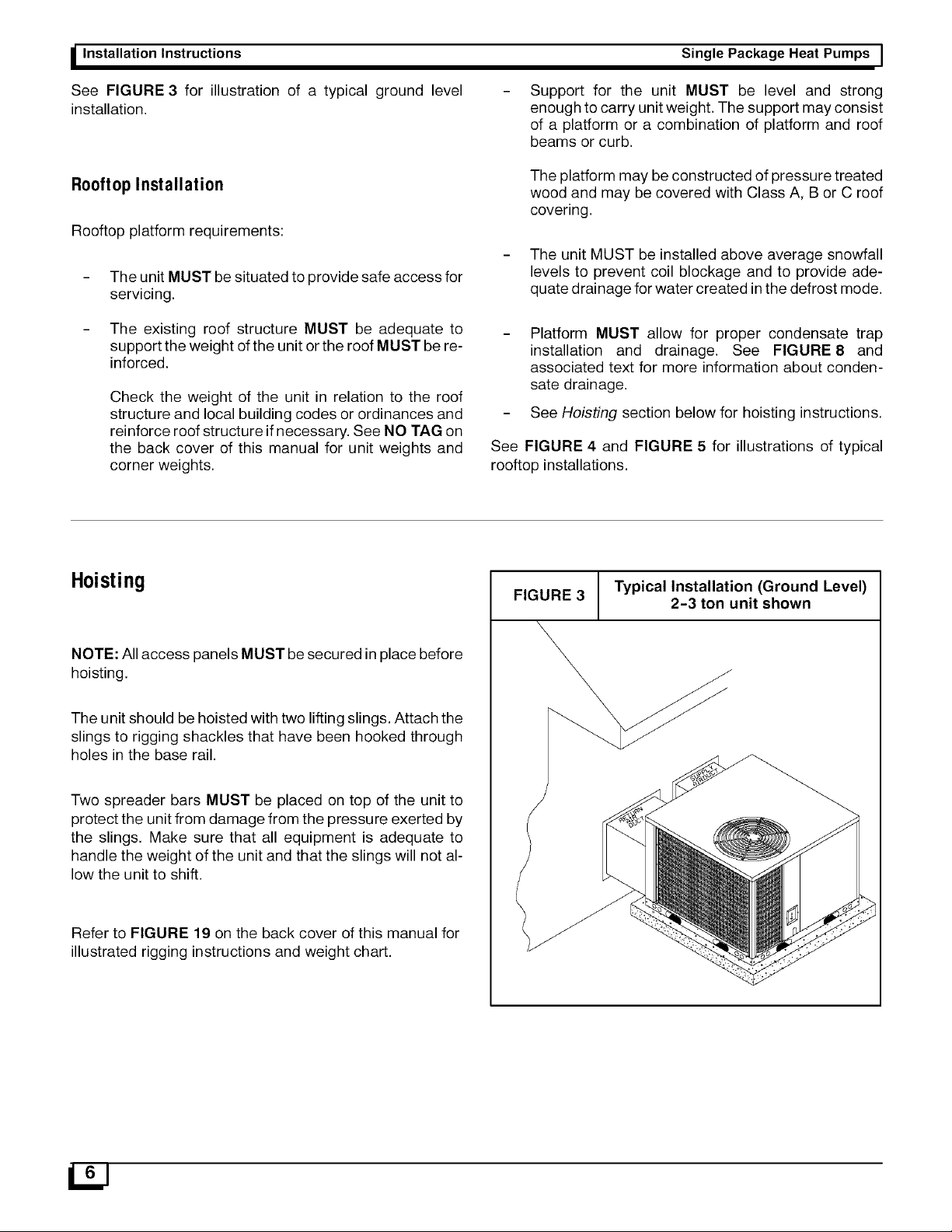
See FIGURE 3 for illustration of a typical ground level
installation.
Rooftop Installation
Rooftop platform requirements:
The unit MUST be situated to provide safe access for
servicing.
The existing roof structure MUST be adequate to
support the weight of the unit orthe roof MUST be re-
inforced.
Check the weight of the unit in relation to the roof
structure and local building codes or ordinances and
reinforce roof structure ifnecessary. See NO TAG on
the back cover of this manual for unit weights and
corner weights.
Support for the unit MUST be level and strong
enough to carry unit weight. The support may consist
of a platform or a combination of platform and roof
beams or curb.
The platform may be constructed of pressure treated
wood and may be covered with Class A, B or C roof
covering.
The unit MUST be installed above average snowfall
levels to prevent coil blockage and to provide ade-
quate drainage for water created in the defrost mode.
Platform MUST allow for proper condensate trap
installation and drainage. See FIGURE8 and
associated text for more information about conden-
sate drainage.
See Hoisting section below for hoisting instructions.
See FIGURE 4 and FIGURE 5 for illustrations of typical
rooftop installations.
Hoisting
NOTE: All access panels MUST be secured inplace before
hoisting.
The unit should be hoisted with two lifting slings. Attach the
slings to rigging shackles that have been hooked through
holes in the base rail.
Two spreader bars MUST be placed on top of the unit to
protect the unit from damage from the pressure exerted by
the slings. Make sure that all equipment is adequate to
handle the weight of the unit and that the slings will not al-
low the unit to shift.
Refer to FIGURE 19 on the back cover of this manual for
illustrated rigging instructions and weight chart.
FIGURE 3
Typical Installation (Ground Level)
2-3 ton unit shown
 Loading...