


C9MPT050F12B1
ICP C9MPT050F12B1, C9MPT075F12A1, C9MPT075F14A2, C9MPT075F14B1, C9MPT100J16A1 Installation Guide
...
90+2-Stage &*9MPT & *9MPV
Variable Speed
SAFETY REQUIREMENTS
Recognize safety information. This is the safety-alert symbolL±_. _ . When you see this symbol on the furnace and in instructions or manuals be alert
to the potential for personal injury.
Understand the signal words DANGER, WARNING, or CAUTION. These words are used with the safety-alert symbol. DANGER identifies the
most serious hazards, those that will result in severe personal injury or death. WARNINGsignifiesahazardthatcouldresultinpersonalinjuryor
death. CAuT__N is used t_ identify unsafe practices that c_u_d resu_t in min_r pers_na_ injury _r _r_duct and pr__erty damage.
Installing and servicing heating equipment can be hazardous due to gas and electrical components. Only trained and qualified personnel should
install, repair, or service heating equipment.
Untrained service personnel can perform basic maintenance functions such as cleaning and replacing air filters. All other operations must be
performed by trained service personnel. When working on heating equipment, observe precautions in the literature, on tags, and on labels attached
to or shipped with the unit and other safety precautions that may apply.
Follow all safety codes. In the United States, follow all safety codes including the current edition National Fuel Gas Code (NFGC) NFPA No.
54/ANSIZ223.1. InCanada, refer tothecurrent editionofthe NationalStandard Canada CAN/CGA-B149.1- and.2-M91 NaturalGasand Propane
InstallationCodes (NSCNGPIC). Wearsafetyglassesandworkgloves. Havefireextinguisher availableduringstart-upandadjustment procedures
and service calls.
These instructions cover minimum requirements and conform to existing national sta nda rds and safety codes. In some insta rices, these instructions
exceed certain local codes and ordinances, especially those that may not have kept up with changing residential construction practices. We requre
these instructions as a minimum for a safe installation.
/X
Manufactured by:
International Comfort Products Corporation (USA)
Lewisburg, TN 37091
Table of Contents
1. Safe Installation Requirements ................. 4
2. Installation ................................ 5
3. Combustion & Ventilation Air .................. 8
4.Vent & Combustion Air Piping ................ 10
5. GasSupply and Piping ...................... 21
6. Electrical Wiring ........................... 25
7.DuctworkandFilter ........................ 26
8. ChecksandAdjustments.................... 30
9.FurnaceMaintenance ....................... 32
10.SequenceofOperation&Diagnostics.......... 32
11.ConcentricVentTermination................. 38
12.TechSupportandParts .................... 41
FIRE OR EXPLOSION HAZARD
This furnace is not designed for use in mobile
homes, trailers or recreational vehicles.
Such use could result in death, bodily injury
and/or property damage.
PrintedinU.S.A. LP1 12/2/2002 440 01 2113 (02)
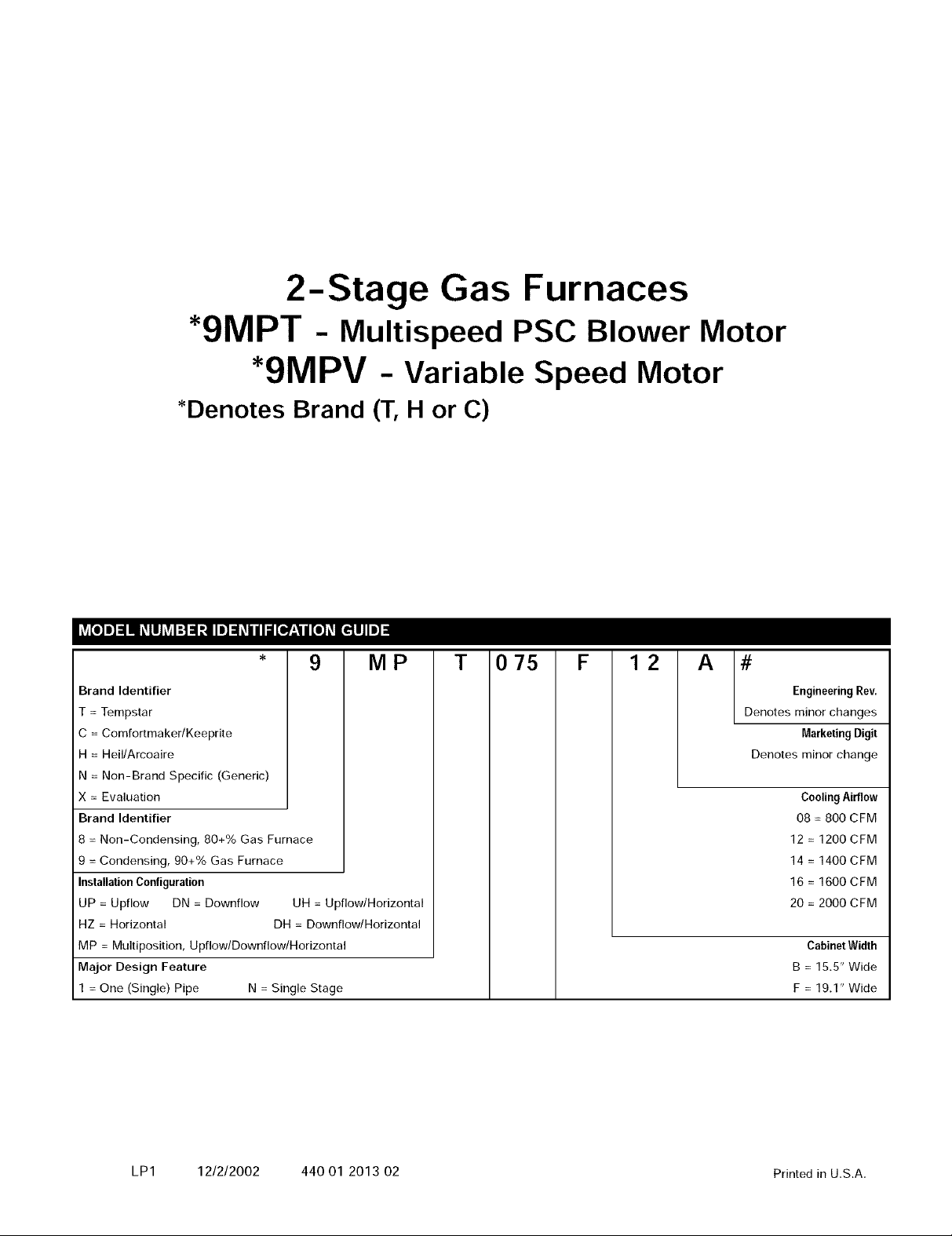
2-Stage Gas Furnaces
*9MPT - Multispeed PSC Blower Motor
*9MPV - Variable Speed Motor
*Denotes Brand (T, H or C)
9 MP
Brand Identifier
= Tempstar
C = Comfortmaker/Keeprite
H = Heil/Arcoaire
N = Non-Brand Specific (Generic)
× = Evaluation
Brand Identifier
8 = Non-Condensing, 80+% Gas Furnace
9 = Condensing, 90+% Gas Furnace
InstallationConfiguration
UP = Upflow DN = Downflow UH = Upflow/Horizontal
HZ = Horizontal DH = Downflow/Horizontal
MP = Multiposition, Upflow/Downflow/Horizontal
Major Design Feature
1 = One (Single) Pipe N = Single Stage
T 075 F 12 A #
EngineeringRev.
Denotes minor changes
MarketingDigit
Denotes minor change
Cooling Airflow
08 = 800 CFM
12 = 1200 CFM
14 = 1400 CFM
16 = 1600 CFM
20 = 2000 CFM
Cabinet Width
B = 15.5" Wide
F = 19.1" Wide
LP1 12/2/2002 440 01 2013 02 Printed in U.S.A.
Dealer Name:
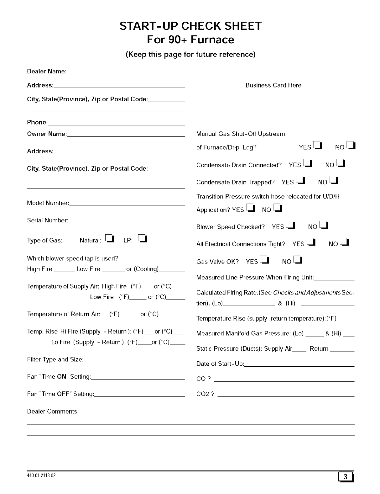
START-UP CHECK SHEET
For 90+ Furnace
(Keep this page for future reference)
Address:
City, State(Province), Zip or Postal Code:
Phone:
Owner Name:
Address:
City, State(Province), Zip or Postal Code:
Model Number:
Serial Number:
Type of Gas: Natural: _ LP:
Which blower speed tap is used?
High Fire __ Low Fire or (Cooling)
Temperature of Supply Air: High Fire (°F)__ or (°C)__
Low Fire (°F).__or (°C)__
Business Card Here
Manual Gas Shut-Off Upstream
of Furnace/Drip- Leg?
Condensate Drain Connected?
Condensate Drain Trapped? YES
Transition Pressure switch hose relocated for U/D/H
Application? YES _ NO
Blower Speed Checked? YES _ NO
All Electrical Connections Tight? YES _ NO
Gas Valve OK? YES _ NO
Measured Line Pressure When Firing Unit:
Calculated Firing Rate:(See Checks andAdjustments Sec-
tion). (Lo) & (Hi)
YES
YES
NOE_
NO
NO
Temperature of Return Air: (°F)__ or (°C)__
Temp. Rise Hi Fire (Supply - Return ):(°F) or (°C)__
Lo Fire (Supply - Return ): (°F) or (°C).__
Filter Type and Size:
Fan "Time ON" Setting:
Fan "Time OFF" Setting:
Dealer Comments:
44001211302
Temperature Rise (supply-return temperature):(°F)__
Measured Manifold Gas Pressure: (Lo) __ & (Hi) __
Static Pressure (Ducts): Supply Air Return
Date of Start-Up:
CO?
CO2 ?
1. Safe Installation Requirements
Installation or repairs made by unqualified persons can
result in hazards to you and others. Installation MUST
conform with local codes or, in the absence of local
codes, with codes of all governmental authorities
havingjurisdiction.
The information contained in this manual is intended
for use by a qualified service technician who is
experienced in such work, who is familiar with all
precautions and safety procedures required in such
work and is equipped with the proper tools and test
instruments.
Failure to carefully read and follow all instructions in
this manual can result in furnace malfunction, death,
personal injury and/or property damage.
NOTE: This furnace is design certified by the Canadian Stan-
dards Association (CSA) for installation in the United States and
Canada. Refer to the appropriate codes, along with Figure 1 or
Figure 2 and this manual, for proper installation.
• Use only the Type of gas approved for this furnace (see
Rating Plate on unit). Overfiring will result in failure of
heat exchanger and cause dangerous operation. (Fur-
naces can be converted to L.R gas with approved kit.)
• Install this furnace only in a location and position as speci-
fied in "lnstallation"pg 5 of these instructions.
• Provide adequate combustion and ventilation air to the
furnace as specified in "Combustion and Ventilation Air"
on pg 8 of these instructions.
• Combustion products must be discharged outdoors. Con-
nect this furnace to an approved vent system only, as spe-
cified in "Combustion and Ventilation Air"on pg 8 of these
instructions.
• Never test for gas leaks with an open flame. Use a com-
mercially available soap solution made specifically for the
detection of leaks to check all connections, as specified in
"Gas Supply and Piping"on pg 32 of these instructions.
• Always install furnace to operate within the furnace's in-
tended temperature-rise range with a duct system which
has an external static pressure within the allowable rat-
ings, as specified in "Technical Support Specifications"
pgs 49 - 51 of these instructions.
• When a furnace is installed so that supply ducts carry air
circulated by the furnace to areas outside the space con-
taining the furnace, the return air shall also be handled by
duct(s) sealed to the furnace casing and terminating out-
side the space containing the furnace.
• A gas-fired furnace for installation in a residential garage
must be installed as specified in "Installation Require-
ments"pg 7 of these instructions.
• This furnace is not to be used for temporary heating of
buildings or structures under construction.
• This furnace is NOT approved for installation in mo-
bile homes, trailers or recreation vehicles.
• Seal around supply and return air ducts.
• Install correct filter type and size.
• Unit MUST be installed so electrical components are pro-
tected from direct contact with water.
NOTE: It is the personal responsibility and obligation of the end
user to contact a qualified installer to ensure that the installation is
adequate and conforms to governing codes and ordinances.
Safety Rules
Your unit is built to provide many years of safe and dependable
service provided it is properly installed and maintained. However,
abuse and/or improper use can shorten the life of the unit and
create hazards for you, the owner.
A. The U.S. Consumer Product Safety Commission recom-
mends that users of gas-burning appliances install carbon
monoxide detectors. There can be various sources of car-
bon monoxide in a building or dwelling. The sources could
be gas-fired clothes dryers, gas cooking stoves, water
heaters, furnaces, gas-fired fireplaces, wood fireplaces,
and several other items. Carbon monoxide can cause seri-
ous bodily injury and/or death. Therefore, to help alert
people of potentially dangerous carbon monoxide levels,
you should have carbon monoxide detectors listed by a na-
tionally recognized agency (e.g. Underwriters Laborato-
ries or CSA International) installed and maintained in the
building or dwelling (see Note below).
Carbon monoxide or "CO" is a colorless and odorless gas
produced when fuel is not burned completely or when the
flame does not receive sufficient oxygen.
B. There can be numerous sources of fire or smoke in a build-
ing or dwelling. Fire or smoke can ca use serious bodily inju-
ry, death, and/or property damage. Therefore, in order to
alert people of potentially dangerous fire or smoke, you
should have fire and smoke detectors listed by Underwrit-
ers Laboratories installed and maintained in the building or
dwelling (see Note below).
Note: The manufacturer of your furnace does not test any de-
tectors and makes no representations regarding any brand
or type of detector.
C. To ensure safe and efficient operation of your unit, you
should do the the following:
1. Thoroughly read this manual and labels on the unit.
This will help you understand how your unit operates and
the hazards involved with gas and electricity.
2. Do not use this unit if any part has been under water.
Immediately call a qualified service technician to inspect
the unit and to replace any part of the control system and
any gas control which has been under water.
3. Never obstruct the vent grilles, or any ducts that pro-
vide air to the unit. Air must be provided for proper com-
bustion and ventilation of flue gases.
Frozen Water Pipe Hazard
FROZEN AND BURST WATER PIPE HAZARD.
Failure to do so may result in burst water pipes, serious
property damage and/or personal injury.
Furnace may shut down. Do not leave your home
unattended for long periods during freezing weather
without turning off water supply and draining water
pipes or otherwise protecting against the risk of frozen
pipes.
Your furnace is designed solely to provide a safe and comfortable
living environment. The furnace is NOT designed to ensure that
water pipes will not freeze. It is equipped with several safety de-
vices that are designed to turn the furnace off and prevent it from
restarting in the event of various potentially unsafe conditions.
[_ 44001211302
Ifyourfurnaceremainsoffforanextendedtime, the pipes in your
home could freeze and burst, resulting in serious water damage.
Water may create a condition in which mold can grow in your
home. Certain types of mold have been reported to cause respi-
ratory problems or other serious health risks. Remedial actions,
including immediately drying all wet items, should be taken quick-
ly to help prevent the development of mold in your home.
If the structure will be unattended during cold weather you should
take these precautions.
Turn off the water supply to the structure and drain the wa-
ter lines if possible and add an antifreeze for potable water
to drain traps and toilet tanks. Open faucets in appropriate
areas.
-or-
Have someone check the structure frequently during cold
weather to make sure it is warm enough to prevent pipes
from freezing. Instruct them on a service agency to call to
provide service, if required.
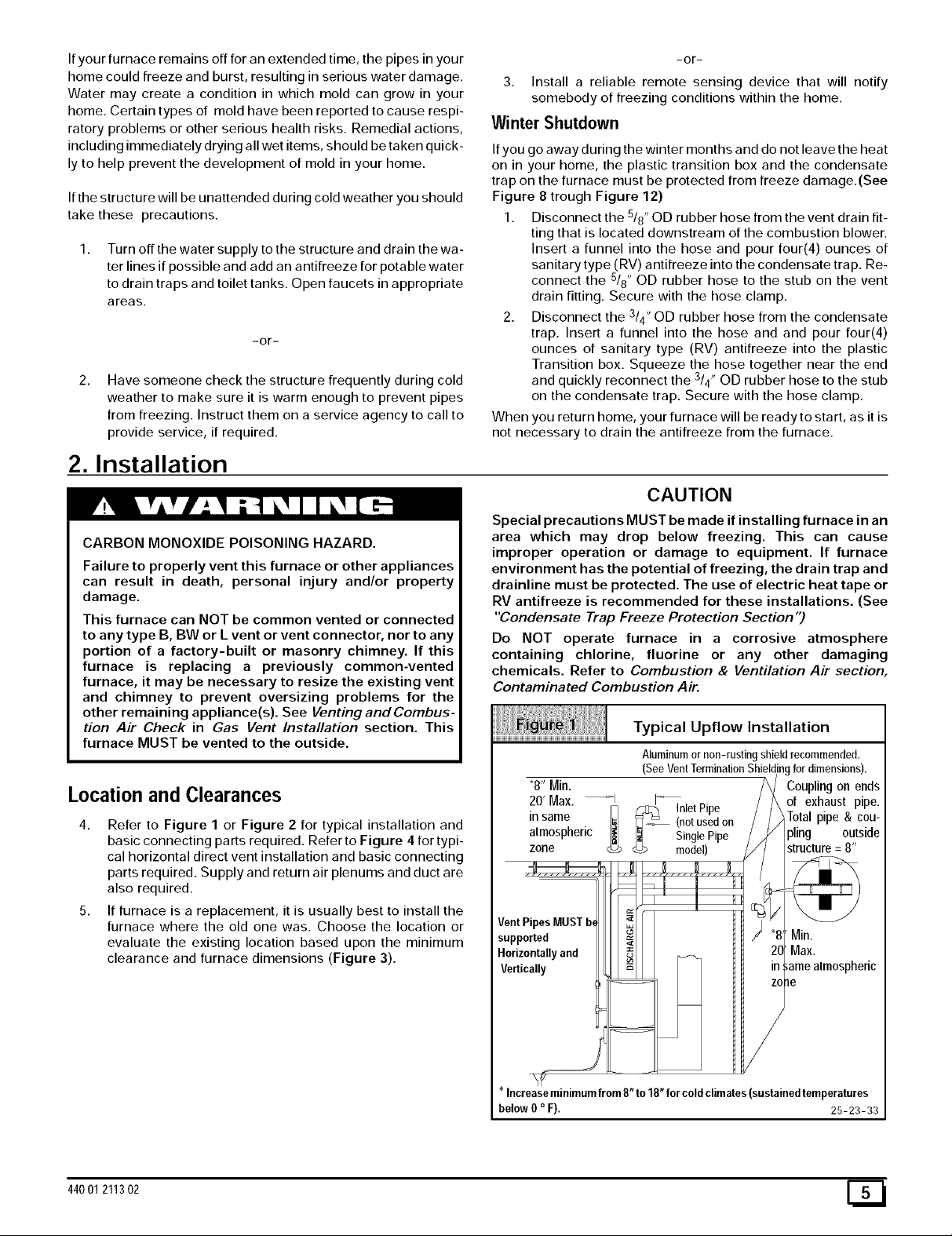
2. Installation
CARBON MONOXIDE POISONING HAZARD.
Failure to properly vent this furnace or other appliances
can result in death, personal injury and/or property
damage.
This furnace can NOT be common vented or connected
to any type B, BW or L vent or vent connector, nor to any
portion of a factory-built or masonry chimney. If this
furnace is replacing a previously common-vented
furnace, it may be necessary to resize the existing vent
and chimney to prevent oversizing problems for the
other remaining appliance(s). See Venting and Combus-
tion Air Check in Gas Vent Installation section. This
furnace MUST be vented to the outside.
Location and Clearances
Refer to Figure 1 or Figure 2 for typical installation and
basic connecting parts required. Refer to Figure 4 for typi-
cal horizontal direct vent installation and basic connecting
parts required. Supply and return air plenums and duct are
also required.
5. If furnace is a replacement, it is usually best to install the
furnace where the old one was. Choose the location or
evaluate the existing location based upon the minimum
clearance and furnace dimensions (Figure 3).
-or-
3. Install a reliable remote sensing device that will notify
somebody of freezing conditions within the home.
Winter Shutdown
If you go away during the winter months and do not leave the heat
on in your home, the plastic transition box and the condensate
trap on the furnace must be protected from freeze damage.(See
Figure 8 trough Figure 12)
1. Disconnect the 5/8" OD rubber hose from the vent drain fit-
ting that is located downstream of the combustion blower.
Insert a funnel into the hose and pour four(4) ounces of
sanitary type (RV) antifreeze into the condensate trap. Re-
connect the 5/8" OD rubber hose to the stub on the vent
drain fitting. Secure with the hose clamp.
2. Disconnect the 3/4" OD rubber hose from the condensate
trap. Insert a funnel into the hose and and pour four(4)
ounces of sanitary type (RV) antifreeze into the plastic
Transition box. Squeeze the hose together near the end
and quickly reconnect the 3/4" OD rubber hose to the stub
on the condensate trap. Secure with the hose clamp.
When you return home, your furnace will be ready to start, as it is
not necessary to drain the antifreeze from the furnace.
CAUTION
Special precautions MUST be made if installing furnace in an
area which may drop below freezing. This can cause
improper operation or damage to equipment. If furnace
environment has the potential of freezing, the drain trap and
drainline must be protected. The use of electric heat tape or
RV antifreeze is recommended for these installations. (See
"Condensate Trap Freeze Protection Section")
Do NOT operate furnace in a corrosive atmosphere
containing chlorine, fluorine or any other damaging
chemicals. Refer to Combustion & Ventilation Air section,
Contaminated Combustion Air.
Typical Upflow Installation
Aluminumornon-rustingshieldrecommended.
(SeeVentTerminationShieldingfordimensions).
"8" Min.
20' Max. _ I_
in same _-_ (notusedon
atmospheric _ SinglePipe
zone _> model)
Vent Pipes MUST
supported
Horizontally and
Vertically
_ InletPipe
Coupling on ends
of exhaust pipe.
pling outside
T0tal pipe & cou-
i_ame atmospheric
44001 211302
?
* increaseminimumfrom8" to 18" for cold climates(sustainedtemperatures
below0 oF), 25-23-33
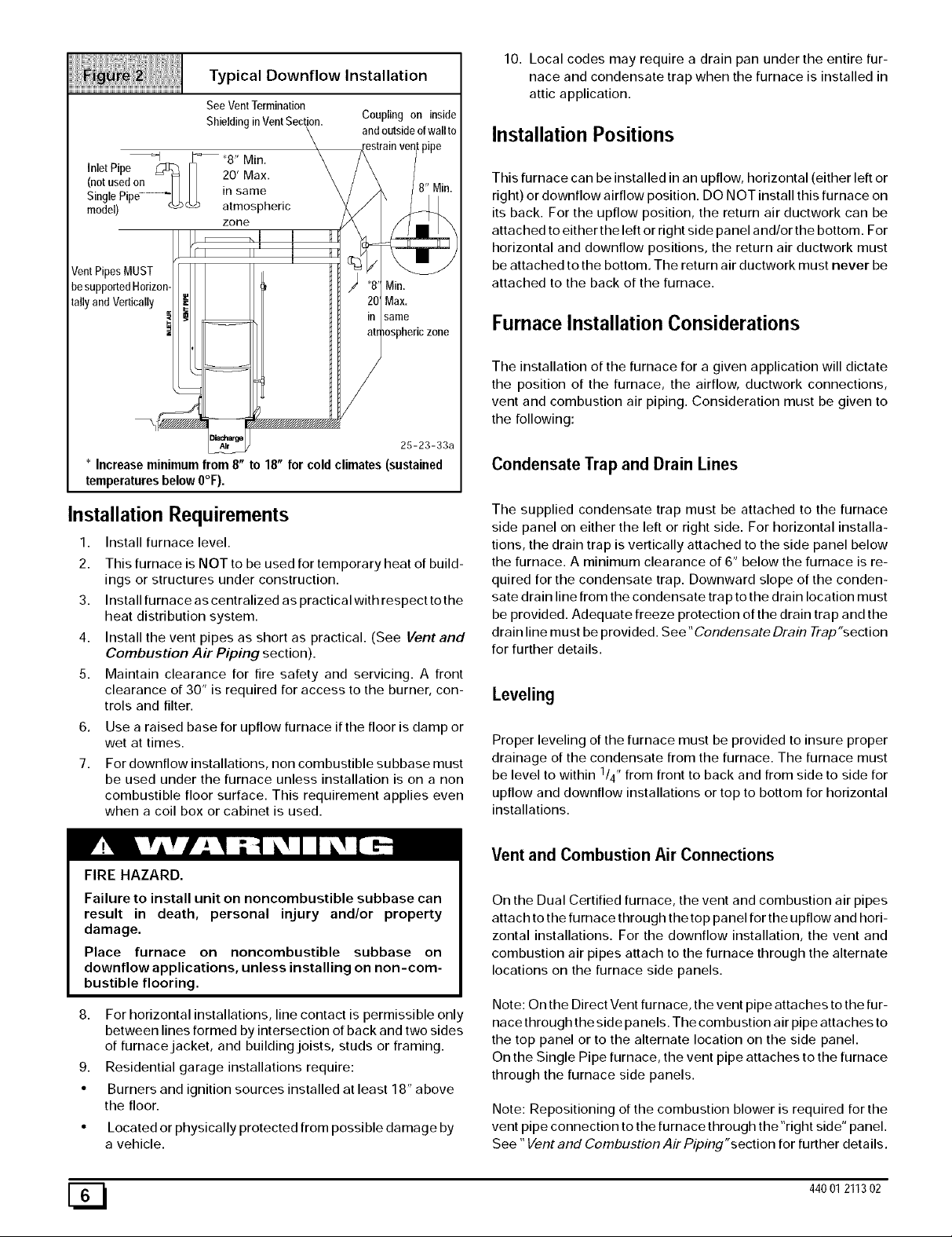
Typical Downflow Installation
See VentTermination
Shieldingin VentSection.
Inlet Pipe C_ Iq .... "
I_ "8" Min
Coupling on inside
andoutsideofwall to
(notusedon- I1H fu ,v,a×.
Single Pipe........... _ in same
model) _ atmospheric
Vent Pip MUST
be supp_ _dHorizor
tally and Vertically
* Increase minimum from 8" to 18" for cold climates (sustained
temperatures below 0°F).
zone
Min.
Max.
same
E _///////////////////////////_
zone
25-23-33a
10. Local codes may require a drain pan under the entire fur-
nace and condensate trap when the furnace is installed in
attic application.
Installation Positions
This furnace can be installed in an upflow, horizontal (either left or
right) or downflow airflow position. DO NOT install this furnace on
its back. For the upflow position, the return air ductwork can be
attached to either the left or right side panel and/or the bottom. For
horizontal and downflow positions, the return air ductwork must
/
be attached to the bottom. The return air ductwork must never be
attached to the back of the furnace.
Furnace Installation Considerations
The installation of the furnace for a given application will dictate
the position of the furnace, the airflow, ductwork connections,
vent and combustion air piping. Consideration must be given to
the following:
Condensate Trap and Drain Lines
Installation Requirements
1. Install furnace level.
2. This furnace is NOT to be used for temporary heat of build-
ings or structures under construction.
3. Install furnace as centralized as practical with respect to the
heat distribution system.
4. Install the vent pipes as short as practical. (See Vent and
Combustion Air Piping section).
5. Maintain clearance for fire safety and servicing. A front
clearance of 30" is required for access to the burner, con-
trols and filter.
6.
Use a raised base for upflow furnace if the floor is damp or
wet at times.
7.
For downflow installations, non combustible subbase must
be used under the furnace unless installation is on a non
combustible floor surface. This requirement applies even
when a coil box or cabinet is used.
FIRE HAZARD.
Failure to install unit on noncombustible subbase can
result in death, personal injury and/or property
damage.
Place furnace on noncombustible subbase on
downflow applications, unless installing on non-com-
bustible flooring.
8. For horizontal installations, line contact is permissible only
between lines formed by intersection of back and two sides
of furnace jacket, and building joists, studs or framing.
9. Residential garage installations require:
• Burners and ignition sources installed at least 18" above
the floor.
Located or physically protected from possible damage by
a vehicle.
The supplied condensate trap must be attached to the furnace
side panel on either the left or right side. For horizontal installa-
tions, the drain trap is vertically attached to the side panel below
the furnace. A minimum clearance of 6" below the furnace is re-
quired for the condensate trap. Downward slope of the conden-
sate drain line from the condensate trap to the drain location must
be provided. Adequate freeze protection of the drain trap and the
drain line must be provided. See "Condensate Drain Trap"section
for further details.
Leveling
Proper leveling of the furnace must be provided to insure proper
drainage of the condensate from the furnace. The furnace must
be level to within 1/4" from front to back and from side to side for
upflow and downflow installations or top to bottom for horizontal
installations.
Vent and Combustion Air Connections
On the Dual Certified furnace, the vent and combustion air pipes
attach to the furnace through the top panel for the upflow and hori-
zontal installations. For the downflow installation, the vent and
combustion air pipes attach to the furnace through the alternate
locations on the furnace side panels.
Note: On the Direct Vent furnace, the vent pipe attaches to the fur-
nace through the side panels. The combustion air pipe attaches to
the top panel or to the alternate location on the side panel.
On the Single Pipe furnace, the vent pipe attaches to the furnace
through the furnace side panels.
Note: Repositioning of the combustion blower is required for the
vent pipe connection to the furnace through the "right side" panel.
See "Vent and Combustion Air Piping"section for further details.
[_ 44001211302
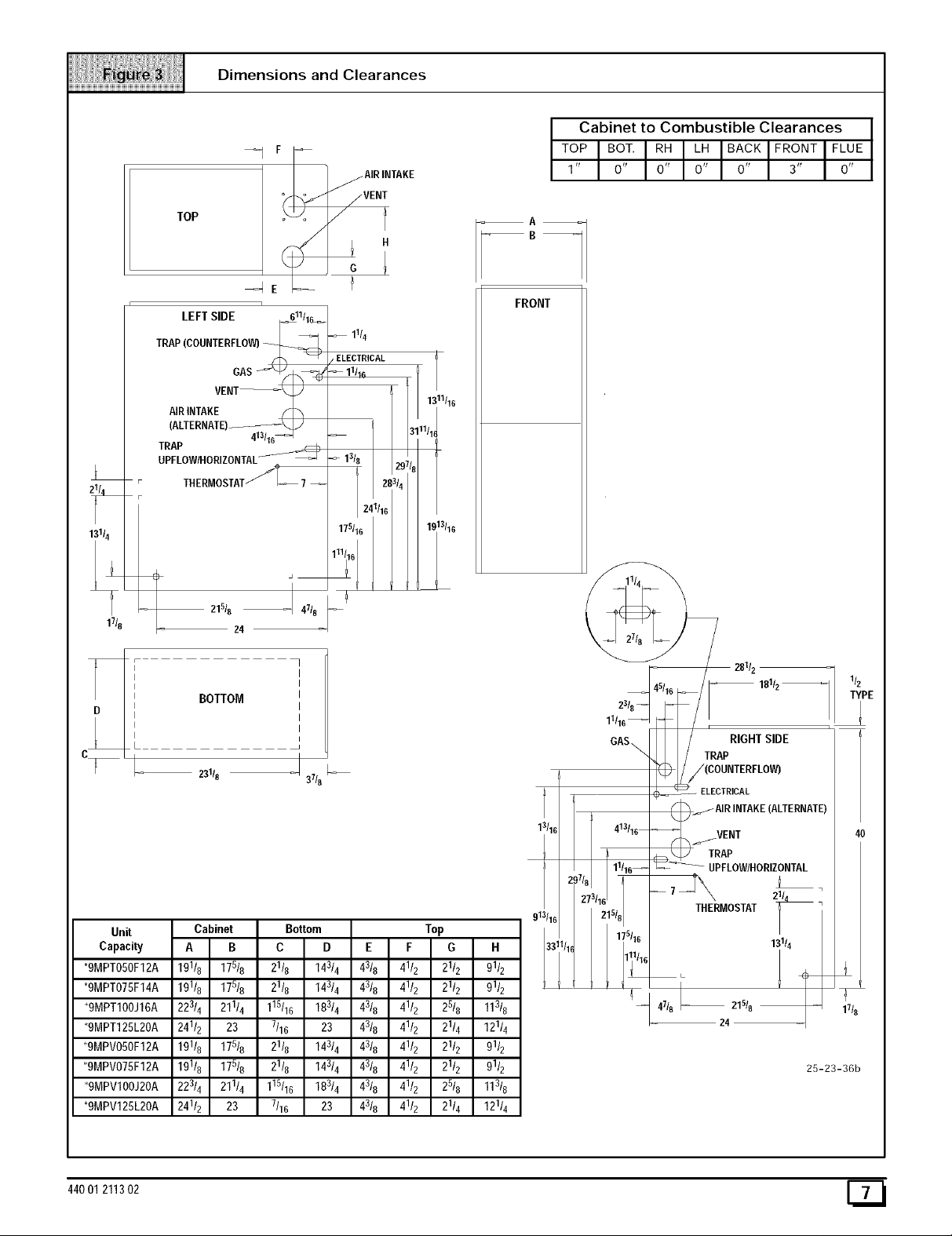
Dimensions and Clearances
_ __ ]_A,R,._KE
TOP
Cabinet to Combustible Clearances
TOPOOT.R_L_OA_KFRO.TFL_
1' O' O' O' O' 3' O'
11/8
1
LEFT SIDE _11/1_
T° ,OOO.T ° LO
VEN
AIRINTAKE S
(ALTERNATE) \
21518
413/16_
I 47t8
24
TRAP
UPFLOW/HORIZONTAL_;_
THERMOSTATf_-_ 7 --
11/4
ELECTRICAL
11/16
_9
'4
BOTTOM
23118 37/8
FRONT
1_11t16
/1_
1.c13t16
__= 281/z --
181/z
11116_ _
GAS_ _ TRApRIGHT SIDE
_._ /(COUNTERFLOW)
( _ ELECTRICAL
Unit
Capacity
*9MPT050F12A
*9MPT075F14A
*9MPT100J16A
*9MPT125L20A
*9MPV050F12A
*9MPV075F12A
*9MPV100J20A
*9MPV125L20A
44001 211302
13/16
913116
33"
111/16_
17/827=/16215t8
413/16
175116
AIRINTAKE(ALTERNATE)
____VENT
TRAP
UPFLOWIHORIZONTAL
MOSTAT
13114
7
17t8
25-23-36b

Horizontal Furnace Installation
This furnace can be installed horizontally in an attic, basement,
crawl space, alcove, or suspended from a ceiling in a basement or
utility room (See Figure 4). Do not install furnace on its back or in
the reverse airflow positions as safety control operation will be ad-
versely affected.
Typical Horizontal Installation
Inlet Pipe (notusedon SinglePipemodel)
Vent
Pipe
If the furnace is to be suspended from the floor joists in a crawl
space or the rafters in an attic, it is necessary to use steel pipe
straps or an angle iron frame to rigidly attach the furnace to pre-
vent movement. These straps should be attached to the furnace
with sheet metal screws and to the rafters or joists with bolts. The
preferred method is to use an angle iron frame bolted to the rafters
or joists. (Take caution to allow door panels to be removed for
maintenance)
If the furnace is to be installed in a crawl space, consult local
codes. A suitable concrete pad or blocks are recommended for
crawl space installation on the ground.
NOTE: 6" bottom clearance required for condensate trap.
Thirty (30) inches between the front of the furnace and adjacent
construction or other appliances MUST be maintained for service
clearance.
Condensate
Trap
25-23-34
NOTE: 5" bottom clearance required for condensate trap.
3. Combustion & Ventilation Air
CARBON MONOXIDE POISONING HAZARD.
Failure to provide adequate combustion and ventilation
air can result in death and/or personal injury.
Use methods described here to provide combustion
and ventilation air.
Air Openings and Connecting Ducts
1. Total input rating for all non direct vent gas appliances
MUST be considered when determining free area of open-
ings.
2. Connect ducts or openings directly to outside.
3. When screens are used to cover openings, they MUST be
no less than 1/4" mesh.
Keep all insulating materials clear from louvered door. Insulating
materials may be combustible.
The horizontal furnaces may be installed directly on combustible
wood flooring or supports as long as all required furnace clear-
ances are met. See Figure 4.
This furnace MUST NOT be installed directly on carpeting or tile
or other combustible material other than wood flooring or sup-
ports.
For horizontal installation over a finished living space. A field fab-
ricated auxiliary drain pan with drain pipe is required to prevent
damage by overflow due to blocked condensate drain.
4. The minimum dimension of rectangular air ducts MUST
NOT be less than 3".
5. When sizing grille or louver, use the free area of opening. If
free area is NOT stamped or marked on grill or louver, as-
sume a 20% free area for wood and 60% for metal.
Confined Space Installation
NOTE: A confined space is defined as an area with less than 50
cubic feet per 1,000 BTUH input rating for all gas appliances
installed in the area.
Requirements
1. Provide confined space with sufficient air for proper com-
bustion and ventilation of flue gases using horizontal or ver-
tical ducts or openings.
2. Figure 5 illustrate how to provide combustion and ventila-
tion air. A minimum of two permanent openings, one inlet
and one outlet, are required.
[_ 44001211302
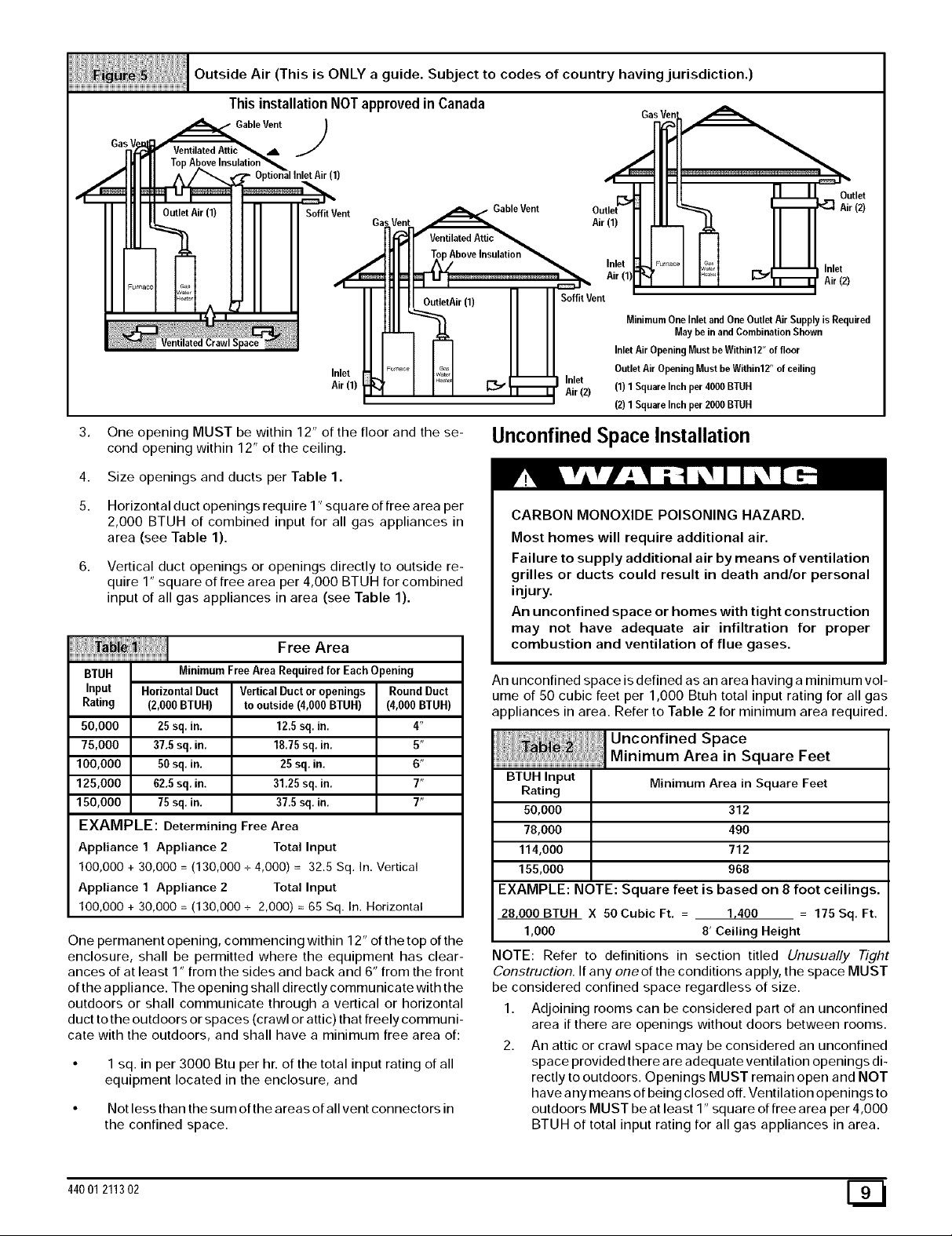
Outside Air (This is ONLY a guide. SubJect to codes of country havingjurisdiction.)
This installation NOTapproved in Canada
Gas
Gable Vent_b. J
(1)
Soffit Vent GableVent
Ga Air (1)
Inlet
Air (1)
J_f I _ _ 1"_ Air (2)
_ Inlet
3. One opening MUST be within 12" of the floor and the se-
cond opening within 12" of the ceiling.
4.
Size openings and ducts per Table 1.
5.
Horizontal duct openings require 1" square of free area per
2,000 BTUH of combined input for all gas appliances in
area (see Table 1).
Vertical duct openings or openings directly to outside re-
quire 1" square of free area per 4,000 BTUH for combined
input of all gas appliances in area (see Table 1).
Free Area
BTUH MinimumFreeAreaRequiredfor Each Opening
Input HorizontalDuct VerticalDuctor openings Round Duct
Rating (2,000BTUH) to outside(4,000BTUH) (4,000BTUH)
50,000 25 sq, in. 12.5sq. in, 4"
75,000 37,5 sq. in. 18.75sq. in. 5"
100,000 50 sq, in. 25 sq. in. 6"
125,000 62,5sq. in. 31,25sq. in. 7"
150,000 75 sq, in. 37.5sq. in, 7"
EXAMPLE: Determining Free Area
Appliance 1 Appliance 2 Total Input
100,000 + 30,000 = (130,000 + 4,000) = 32.5 Sq. In. Vertical
Appliance 1 Appliance 2 Total Input
100,000 + 30,000 = (130,000 + 2,000) = 65 Sq. In. Horizontal
One permanent opening, commencing within 12" of the top of the
enclosure, shall be permitted where the equipment has clear-
ances of at least 1" from the sides and back and 6" from the front
of the appliance. The opening shall directly communicate with the
outdoors or shall communicate through a vertical or horizontal
duct to the outdoors or spaces (crawl or attic) that freely communi-
cate with the outdoors, and shall have a minimum free area of:
• 1 sq. in per 3000 Btu per hr. of the total input rating of all
equipment located in the enclosure, and
• Not less than the sum ofthe areas of all vent connectors in
the confined space.
AboveInsulation
Air (1) Soffit Vent
Inlet
MinimumOne Inlet and OneOutlet Air SupplyisRequired
May be in and Combination Shown
Inlet Air Opening MustbeWithin12" of floor
Outlet Air Opening Must be Within12" of ceiling
(1) 1SquareInch per 4000BTUH
(2) 1SquareInch per 2000BTUH
Unconfined Space Installation
CARBON MONOXIDE POISONING HAZARD.
Most homes will require additional air.
Failure to supply additional air by means of ventilation
grilles or ducts could result in death and/or personal
injury.
An unconfined space or homes with tight construction
may not have adequate air infiltration for proper
combustion and ventilation of flue gases.
An unconfined space is defined as an area having a minimum vol-
ume of 50 cubic feet per 1,000 Btuh total input rating for all gas
appliances in area. Refer to Table 2 for minimum area required.
BTUH Input
Rating
50,000
78,000
114,000
155,000
EXAMPLE: NOTE: Square feet is based on 8 foot ceilings.
28,000BTUH X 50CubicFt, = 1,400 = 175Sq, Ft.
1,000 8' Ceiling Height
NOTE: Refer to definitions in section titled Unusually #_Tht
Construction. If any oneof the conditions apply, the space MUST
be considered confined space regardless of size.
1. Adjoining rooms can be considered part of an unconfined
area if there are openings without doors between rooms.
2. An attic or crawl space may be considered an unconfined
space provided there are adequate ventilation openings di-
rectly to outdoors. Openings MUST remain open and NOT
have any means of being closed off. Ventilation openings to
outdoors MUST be at least 1" square of free area per 4,000
BTUH of total input rating for all gas appliances in area.
Minimum Area in Square Feet
312
490
712
968
Inlet
Air (2)
Outlet
Air (2)
44001 211302 E_I
3. Installairintakeaminimumof12"abovemaximumsnow
levelandclearofanyobstruction.Ductorventilationopen-
ingrequiresonesquareinchoffreeareaper4,000BTUH
oftotalinputratingforallgasappliancesinarea.
4. AirinletMUSTbescreenedwithnotlessthan114"mesh
screen.
Unusually Tight Construction
In unconfined spaces, infiltration may be adequate to provide air
for combustion, ventilation and dilution of flue gases. However, in
buildings with unusually tight construction, additional air MUST
be provided using the methods described in section titled Con-
fined Space Installation:
Unusually tight construction is defined as: Construction with
1. Walls and ceilings exposed to the outside have a continu-
ous, sealed vapor barrier. Openings are gasketed or
sealed and
2,
Doors and opeRable windows are weather stripped and
3.
Other openings are caulked or sealed. These include joints
around window and door frames, between sole plates and
floors, between wall-ceiling joints, between wall panels, at
penetrations for plumbing, electrical and gas lines, etc.
Ventilation Air
Some provincial codes and local municipalities require ventilation
or make-up air be brought into the conditioned space as replace-
ment air. Whichever method is used, the mixed return air temper-
ature across the heat exchanger MUST not fall below 60 ° F or flue
gases will condense in the heat exchanger. This will shorten the
life of the heat exchanger and possibly void your warranty.
Venting and Combustion Air Check
The following information is supplied to allow the installer to make
adjustments to the setup of existing appliances, IF REQUIRED,
based on good trade practices, local codes, and good judgement
of the installer. Manufacturer does NOT take responsibility for
modifications made to existing equipment.
NOTE: If this installation replaces an existing furnace from a
commonly vented system, the original venting system may no
longer be sized to properly vent the attached appliances. An im-
properly sized venting system may cause the formation of con-
densate in the vent or the leakage or spillage of vent gases. To
make sure there is adequate combustion air for all appliances,
MAKE THE FOLLOWING CHECK.
1. Seal any unused openings in the venting system.
Visually inspect the venting system for proper size and hor-
izontal pitch to ensure there is no blockage or restriction,
leakage, corrosion or other deficiencies which could cause
an unsafe condition.
3. Insofar as is practical, close all doors and windows and all
doors between the space in which the appliance(s) remain-
ing connected to the venting system are located and other
spaces of the building.
4. Turn on clothes dryers and any appliance not connected to
the venting system. Turn on any exhaust fans, such as
range hoods and bathroom exhausts, so they will operate
at maximum speed. Do not operate a summer exhaust fan.
Close fireplace dampers.
5. Follow the lighting instructions for each appliance being in-
spected. Adjust thermostat so appliance(s) will operate
continuously.
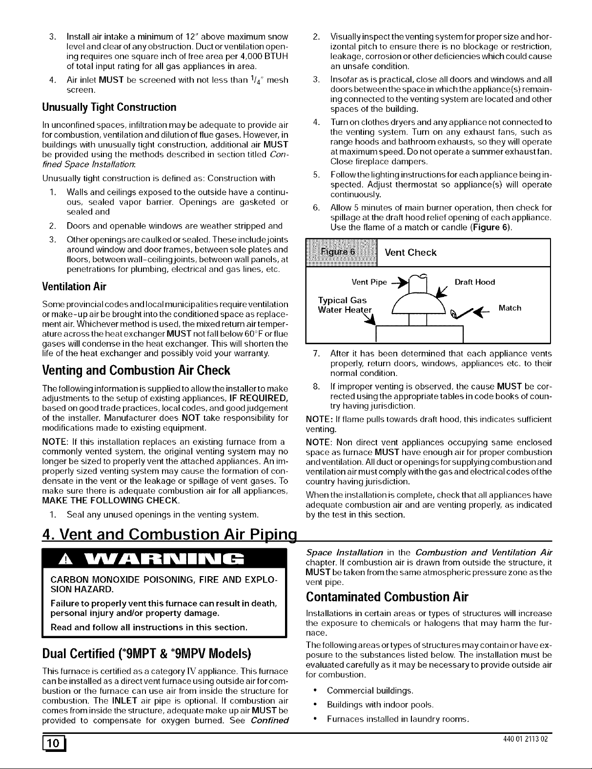
6. Allow 5 minutes of main burner operation, then check for
spillage at the draft hood relief opening of each appliance.
Use the flame of a match or candle (Figure 6).
Vent Check
VentPipe --_1 I A/ Draft Hood
Typical Gas
Water Heater _,,/_-
Match
I l
7.
After it has been determined that each appliance vents
properly, return doors, windows, appliances etc. to their
normal condition.
8. If improper venting is observed, the cause MUST be cor-
rected using the appropriate tables in code books of coun-
try having jurisdiction.
NOTE: If flame pulls towards draft hood, this indicates sufficient
venting.
NOTE: Non direct vent appliances occupying same enclosed
space as furnace MUST have enough air for proper combustion
and ventilation. All duct or openings for supplying combustion and
ventilation air must comply with the gas and electrical codes of the
country having jurisdiction.
When the installation is complete, check that all appliances have
adequate combustion air and are venting properly, as indicated
by the test in this section.
4. Vent and Combustion Air Pi igLEg
Space Installation in the Combustion and Ventilation Air
chapter. If combustion air is drawn from outside the structure, it
CARBON MONOXIDE POISONING, FIRE AND EXPLO-
SION HAZARD.
Failure to properly vent this furnace can result in death,
personal injury and/or property damage.
Read and follow all instructions in this section.
Dual Certified (*9MPT & *9MPV Models)
This furnace is certified as a category [V appliance. This furnace
can be installed as a direct vent furnace using outside air for com-
bustion or the furnace can use air from inside the structure for
combustion. The INLET air pipe is optional. If combustion air
comes from inside the structure, adequate make up air MUST be
provided to compensate for oxygen burned. See Confined
[_ 44001211302
MUST be taken from the same atmospheric pressure zone as the
vent pipe.
Contaminated Combustion Air
Installations in certain areas or types of structures will increase
the exposure to chemicals or halogens that may harm the fur-
Race.
The following a reas or types of structures may contain or have ex-
posure to the substances listed below. The installation must be
evaluated carefully as it may be necessary to provide outside air
for combustion.
• Commercial buildings.
• Buildings with indoor pools.
• Furnaces installed in laundry rooms.
• Furnacesinstalledinhobbyorcraftrooms.
• Furnacesinstallednearchemicalstorageareas.
• Permanentwavesolutionsforhair.
• Chlorinatedwaxesandcleaners.
• Chlorinebasedswimmingpoolchemicals.
• Watersofteningchemicals.
• De-icingsaltsorchemicals.
• Carbontetrachloride.
• Halogentyperefrigerants.
• Cleaningsolvents(suchasperchloroethylene).
• Printinginks,paintremovers,varnishes,etc.
• Hydrochloricacid.
• SulfuricAcid.
• Solventcementsandglues.
• Antistaticfabricsoftenersforclothesdryers.
• Masonryacidwashingmaterials.
Vent and Combustion Air Piping Guidelines
NOTE: All vent piping MUST be installed in compliance with local
codes or ordinances, these instructions, good trade practices,
and codes of country having jurisdiction.
1. Determine the best routing and termination for the vent
pipe and air inlet pipe by referring to all of the instructions
and guidelines in this Section.
2. Determine the size required for the vent pipe and air inlet
pipe.
3. Loosely assemble all venting parts without adhesive (pipe
joint cement) for correct fit before final assembly.
Use of vertical piping is preferred because there will be
some moisture in the flue gases that may condense as it
leaves the vent pipe (See Special Instruction For Horizon-
tal Vents).
5. The vertical vent pipe MUST be supported so that no
weight is allowed to rest on the combustion blower.
6. Exhaust vent piping or air inlet piping diameter MUST NOT
be reduced.
All exhaust vent piping from the furnace to termination
MUST slope upwards. A minimum of 1/4" per foot of run is
required to properly return condensate to the furnace drain
system.
Use DWV type long radius elbows whenever possible, as
they provide for the minimum slope on horizontal runs and
they provide less resistance in the vent system. If DWV el-
bows cannot be used, use two, 45 ° elbows when possible.
On horizontal runs the elbows can be slightly misaligned to
provide the correct slope.
9. All horizontal pipe runs MUST be supported at least every
five feet with galvanized strap or other rust resistant materi-
al. NO sags or dips are permitted.
10. All vertical pipe runs MUST be supported every six feet
where accessible.
11. The maximum pipe length is 40' total in the inlet oroutlet
side of the system. Up to five, 90 ° elbows can be used on
the inlet orthe outlet. With the Concentric Vent Termination
Kits (NAHAOOICV or NAHAOO2CV), the maximum pipe
length is 35' with 4 90 ° elbows. If more elbows are required,
reduce the length of both the inlet and exhaust pipes 5' for
each additional elbow used. (See Table 3 or Table 4).
12. The minimum pipe run length is 2'.
13. The piping can be run in the same chase or adJacent to sup-
ply or vent pipe for water supply or waste plumbing. It can
also be run in the same chase with a vent from another 90+
furnace.
NOTE: In NO case can the piping be run in a chase where
temperatures can exceed 140 ° F. or where radiated heat
from adjacent surfaces would exceed 140 ° F.
14. The vent outlet MUST be installed to terminate in the same
atmospheric pressure zone as the combustion air inlet.
15. The vent system can be installed in an existing unused
chimney provided that:
• Both the exhaust vent and air intake run the length of the
chimney.
• No other gas fired appliance or fireplace (solid fuel) is
vented into the chimney.
• The top of the chimney MUST be sealed flush or crowned
up to seal against rain or melting snow so ONLY the piping
protrudes.
• The termination clearances shown in Figure 7 are main-
tained.
16. Furnace applications with vertical vents requiring vent di-
ameter increaser fittings must have increaser fittings
installed in vertical portion of the vent. Condensate will be
trapped in the vent if the vent diameter is increased prior to
having an elbow turned upward. This could cause nui-
sance tripping of the pressure switch.
Piping Insulation Guidelines
NOTE: Use closed cell, neoprene insulation or equivalent. If Fi-
berglass or equivalent insulation is used it must have a vapor bar-
rier. Use R values of 7 up to 10', R-11 if exposure exceeds 10'. If
Fiberglass insulation is used, exterior to the structure, the pipe
MUST be boxed in and sealed against moisture.
1. .When the vent or combustion air pipe height above the
roof exceeds 30", or if an exterior vertical riser is used on a
horizontal vent to get above snow levels, the exterior por-
tion MUST be insulated.
2. When combustion air inlet piping is installed above a sus-
pended ceiling, the pipe MUST be insulated with moisture
resistant insulation such as Armaflex or other equivalent
type of insulation.
3. Insulate combustion air inlet piping when run in warm, hu-
mid spaces such as basements.
Sizing Combustion Air and Vent Pipe
Consult Table 3 or Table 4 to select the proper diameter exhaust
and combustion air piping. Exhaust and combustion air piping is
sized for each furnace Btuh size based on total lineal vent length
(on inlet or outlet side), and number of 90 ° elbows required.
1. Double Pipe Installation-If installing as a direct-vent ap-
pliance, consult Table 4 to select the proper diameter ex-
haust and combustion air piping. Exhaust and combustion
air piping is sized for each furnace Btuh size based on total
lineal vent length (on inlet oroutlet side), and number of 90 °
elbows required.
44001 211302 E_
2. SinglePipeInstallation-If installing as a non-direct vent
appliance, (single outlet pipe and no inlet pipe) refer to
Table 3. The table shows the maximum number of elbows
allowed with any given pipe diameter and length of run.
3. Use of Elbows-Two 45 ° elbows can be substituted forone
90 ° elbow. The elbow or elbows used for vent termination
outside the structure ARE counted, including elbows need-
ed to bring termination above expected snow levels. The
elbow inside the furnace on the *9MPD IS NOT included in
the count.
Pipe Diameter Table
Single Piping ONLY
50,000 & 75,000 Btuh Furnaces
40' & (5) 90 ° elbows with 2" PVC pipe or
100,000 Btuh Furnace
40' & (5) 90° elbows with 3" PVC pipe
125,000 Btuh Furnace
40' & (5) 90° elbows with 3" PVC pipe
Elbows are DWV Long Radius Type for 2" and 3" vents.
If more than five elbows are required, reduce the length of
both the inlet and exhaust pipes 5' for each additional elbow
used.
NOTE: It is allowable to use larger diameter pipe and fitting than
shown in the tables but not smaller diameters than shown.
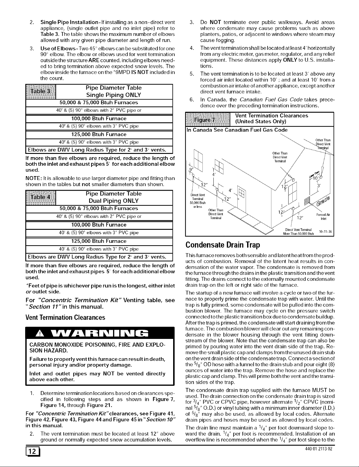
3. Do NOT terminate over public walkways. Avoid areas
where condensate may cause problems such as above
planters, patios, or adjacent to windows where steam may
cause fogging.
4. The vent termination shall be located at least 4' horizontally
from any electric meter, gas meter, regulator, and any relief
equipment. These distances apply ONLY to U.S. installa-
tions.
The vent termination is to be located at least 3' above any
forced air inlet located within 10' ; and at least 10' from a
combustion air intake of another appliance, except another
direct vent furnace intake.
In Canada, the Canadian Fuel Gas Code takes prece-
dence over the preceding termination instructions.
Vent Termination Clearances
(United States Only)
In Canada See Canadian Fuel Gas Code
OtherThan
Other Than
DirectVent
Terminal
Pipe Diameter Table
Dual Piping ONLY
50,000 & 75,000 Btuh Furnaces
40' & (5) 90 ° elbows with 2" PVC pipe or
100,000 Btuh Furnace
40' & (5) 90° elbows with 3" PVC pipe
125,000 Btuh Furnace
40' & (5) 90° elbows with 3" PVC pipe
Elbows are DWV Long Radius Type for 2" and 3" vents.
If more than five elbows are required, reduce the length of
both the inlet and exhaust pipes 5' for each additional elbow
used.
*Feet of pipe is whichever pipe run is the longest, either inlet
or outlet side.
For "Concentric Termination Kit" Venting table, see
"Section 11" in this manual.
Vent Termination Clearances
CARBON MONOXIDE POISONING, FIRE AND EXPLO-
SION HAZARD.
Failure to properly vent this furnace can result in death,
personal injury and/or property damage.
Inlet and outlet pipes may NOT be vented directly
above each other.
1. Determine termination locations based on clearances spe-
cified in following steps and as shown in Figure 7,
Figure 14, through Figure 21.
For "Concentric Termination Kit" clearances, see Figure 41,
Figure 42, Figure 43, Figure 44 and Figure 45 in "Section 10"
in this manual.
2. The vent termination must be located at least 12" above
ground or normally expected snow accumulation levels.
DirectVent
Terminal
50,000 Btuh
orless
OtherThan
Direcl Vent Forced Air
Terminal 12" Inlm
DirectVentTerminal
MoreThan 50,000Btuh
10-11-36
Condensate DrainTrap
This furnace removes both sensible and latent heat from the prod-
ucts of combustion. Removal of the latent heat results in con-
densation of the water vapor. The condensate is removed from
the furnacethrough the drains in the plastic transition and thevent
fitting. The drains connect to the externally mounted condensate
drain trap on the left or right side of the furnace.
The startup of a new furnace will involve a cycle or two of the fur-
nace to properly prime the condensate trap with water. Until the
trap is fully primed, some condensate will be pulled into the com-
bustion blower. The furnace may cycle on the pressure switch
connected to the plastic transition box due to condensate buildup.
After the trap is primed, the condensate will start draining from the
furnace. The combustion blower will clear out any remaining con-
densate in the blower housing through the vent fitting down-
stream of the blower. Note that the condensate trap can also be
primed by pouring water into the vent drain side of the trap. Re-
move the small plastic cap and clamps from the unused drain stub
on the vent drain side of the condensatetrap. Connect a section of
the 5/8" OD hose with a funnel to the drain stub and pour eight (8)
ounces of water into the trap. Remove the hose and replace the
plastic cap and clamp. This will prime both the vent and the transi-
tion sides of the trap.
The condensate drain trap supplied with the furnace MUST be
used. The drain connection on the condensate drain trap is sized
for 3/4" PVC or CPVC pipe, however alternate 1/2" CPVC (nomi-
nal 5/8" O.D.) or vinyl tubing with a minimum inner diameter (I.D.)
of 5/8" may also be used, as allowed by local codes. Alternate
drain pipes and hoses may be used as allowed by local codes.
The drain line must maintain a 1/4" per foot downward slope to-
ward the drain. 1/4" per foot is recommended. Installation of an
overflow line is recommended when the 1/4" per foot slope to the
[_ 44001211302

condensatedraincannotbemaintained.SeeFigure1forproper
routingandinstallationoftheoverflow.
DONOTtrapthedrainlineinanyotherlocationthanatthecon-
densatedraintrapsuppliedwiththefurnace.
FROZEN AND BURST WATER PIPE HAZARD.
If a condensate pump is installed, a plugged condensate
drain or a failed pump may cause the furnace to shut
down. Do not leave the home unattended during freezing
weather without turning off water supply and draining
water pipes or otherwise protecting against the risk of
frozen pipes.
Failure to do so may result in burst water pipes, serious
property damage and/or personal injury.
If possible DO NOT route the drain line where it may freeze. The
drain line must terminate at an inside drain to prevent freezing of
the condensate and possible property damage.
1. A condensate sump pump MUST be used if required by lo-
cal codes, or if no indoor floor drain is available. The con-
densate pump must be approved for use with acidic
condensate.
A plugged condensate drain line or a failed condensate
pump will allow condensate to spill. If the furnace is
installed where a condensate spill could cause damage, it
is recommended that an auxiliary safety switch be installed
to prevent operation of the equipment in the event of pump
failure or plugged drain line. If used, an auxiliary safety
switch should be installed in the R circuit (low voltage)
ONLY.
If the auxiliary switch inthe condensate pump is used, the
furnace may shut down due to a blocked condensate line or
failed pump. Toprevent frozen water pipes see the "Frozen
Water Pipe Hazard" section on Page 4 of this manual.
Condensate Drain Trap Freeze Protection
Special precautions MUST be made if installing furnace in an
area which may drop below freezing. This ca n ca use improper op-
eration or damage to the equipment. If the the furnace environ-
ment has the potential of freezing, the drain trap and drain line
must be protected. Use 3 to 6 watt per foot at 115 volt, 40 ° F self-
regulating shielded and waterproof heat tape. Wrap the drain trap
and drain line with the heat tape and secure with the ties. Follow
the heat tape manufacturer's recommendations.
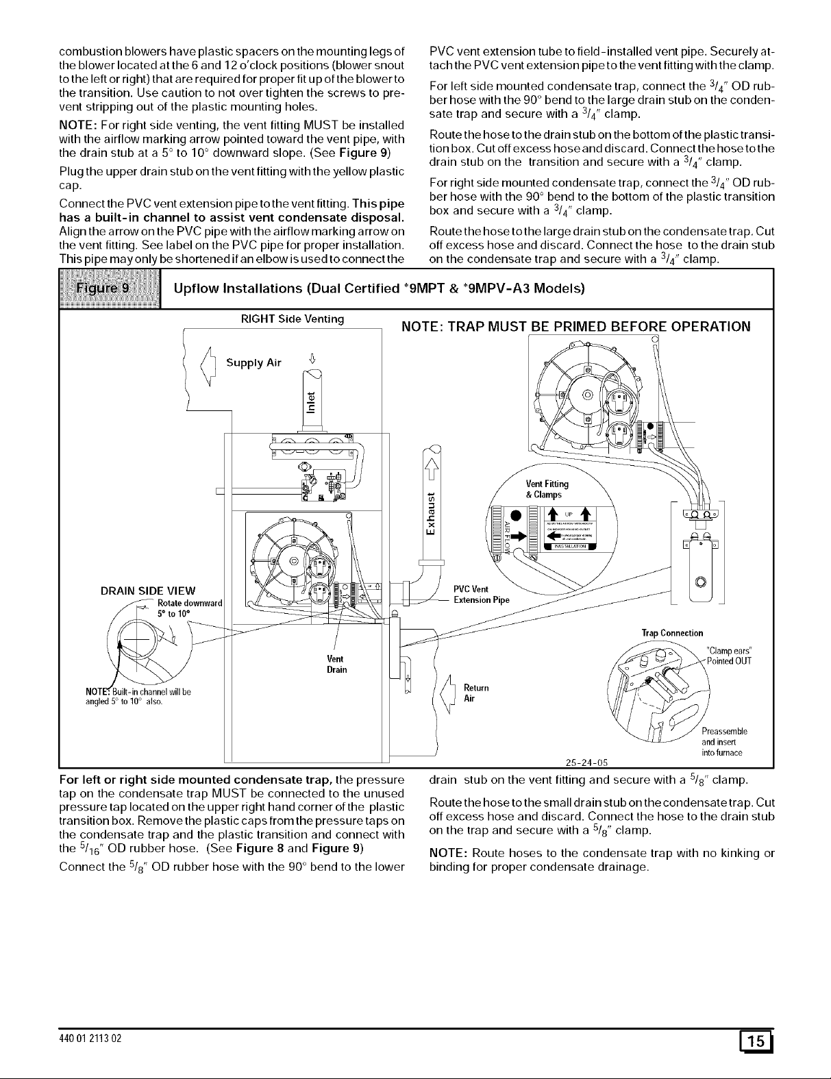
44001 211302 [_
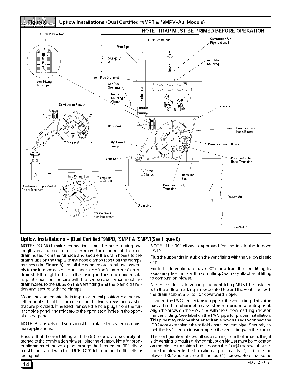
Upflow Installations (Dual Certified *9MPT & *9MPV-A3 Models)
YellowPlastic Cap
Supply
Air
VentPipe
NOTE: TRAP MUST BE PRIMED BEFORE OPERATION
TOP Venting
Combustion Air
Pipe(optional)
Coupling
VentFitting
& Clamps
Condensate Trap& Gasket
(Leftor RightSide)
CombustionBlower
Trap Connection "Clamp ears"
"_ /f// _?reassemble&
VentPipe Grommet
Rubber
90° Elbow
5/8" Hose&
Clamps
Plastic Cap
ointed OUT
insert into furnace
©
314"Hose
& Clamps Transition
Pressure Switch,
Transition
\ DrainLine
Hose, Blower
Blower
Hose,Transition
Box
Return Air
Upflow Installations - (Dual Certified *9MPD, *9MPT & *9MPV)(See Figure 8)
NOTE: DO NOT make connections until the hose routing and
lengths have been determined. Remove the condensate trap and
drain hoses from the furnace and secure the drain hoses to the
drain stubs on the trap with the hose clamps (position the clamps
as shown in Figure 8). Install the condensate trap/hose assem-
bly to the furnace casing. Hook one side of the "clamp ears" on the
drain stub through the hole in the casing and push the condensate
trap into position. Secure with the two screws. Reconnect the
drain hoses to the stubs on the vent fitting and the plastic transi-
tion and secure with the clamps.
Mount the condensate drain trap in a vertical position to either the
left or right side of the furnace using the two screws and gasket
that are provided. If needed, remove the hole plugs from the fur-
nace side panel and relocate to the open set of holes in the oppo-
site side panel.
NOTE: All gaskets and seals must be in place for sealed combus-
tion applications.
Ensure that the vent fitting and the 90 ° elbow are securely at-
tached to the combustion blower using the clamps. Note for prop-
er alignment of the vent pipe through the furnace the 90 ° elbow
must be installed with the "UPFLOW" lettering on the 90 ° elbow
facing out.
NOTE: The 90° elbow is approved for use inside the furnace
ONLY.
Plug the upper drain stub on the vent fitting with the yellow plastic
cap.
For left side venting, remove 90 ° elbow from the vent fitting by
loosening the clamp on the vent fitting. Securely attach vent fitting
to combustion blower.
NOTE: For left side venting, the vent fitting MUST be installed
with the airflow marking arrow pointed toward the vent pipe, with
the drain stub at a 5° to 10 ° downward slope.
Connect the PVC vent extension pipe to the vent fitting. This pipe
has a built-in channel to assist vent condensate disposal.
Align the arrow on the PVC pipe with the airflow marking arrow on
the vent fitting. See label on the PVC pipe for proper installation.
This pipe may only be shortened if an elbow is used to connect the
PVC vent extension tube to field-installed vent pipe. Securely at-
tach the PVC vent extension pipe to the vent fitting with the clamp.
This configuration allows left side venting from the furnace. If right
side venting is required, the combustion blower must be relocated
on the plastic transition box. Loosen the four(4) screws that se-
cure the blower to the transition approximately 1/2". Rotate the
blower 180 ° and secure with the four(4) screws. Note that some
25-24-11a
[_ 44001211302
combustionblowershaveplasticspacersonthemountinglegsof
theblowerlocatedatthe6and12o'clockpositions(blowersnout
totheleftorright)thatarerequiredforproperfitupoftheblowerto
thetransition.Usecautiontonotovertightenthescrewstopre-
ventstrippingoutoftheplasticmountingholes.
NOTE:Forrightsideventing,theventfittingMUSTbeinstalled
withtheairflowmarkingarrowpointedtowardtheventpipe,with
thedrainstubata5°to10°downwardslope.(SeeFigure9)
Plugtheupperdrainstubontheventfittingwiththeyellowplastic
cap.
ConnectthePVCventextensionpipetotheventfitting.Thispipe
hasabuilt-inchanneltoassistventcondensatedisposal.
AlignthearrowonthePVCpipewiththeairflowmarkingarrowon
theventfitting.SeelabelonthePVCpipeforproperinstallation.
Thispipemayonlybeshortenedifanelbowisusedtoconnectthe
Upflow Installations (Dual Certified *9MPT & *91VlPV-A3 Models)
RIGHTSideVenting NOTE: TRAP MUST BE PRIMED BEFORE OPERATION
Supply Air '_
PVCventextensiontubetofield-installedventpipe.Securelyat-
tachthePVCventextensionpipetotheventfittingwiththeclamp.
Forleftsidemountedcondensatetrap,connectthe3/4"ODrub-
berhosewiththe90°bendtothelargedrainstubontheconden-
satetrapand secure with a 3/4" clamp.
Route the hose to the drain stub on the bottom of the plastic transi-
tion box. Cut off excess hose and discard. Connect the hose to the
drain stub on the transition and secure with a 3/4" clamp,
For right side mounted condensate trap, connect the 3/4" OD rub-
ber hose with the 90 ° bend to the bottom of the plastic transition
box and secure with a 3/4" clamp.
Route the hose to the large drain stub on the condensate trap. Cut
off excess hose and discard. Connect the hose to the drain stub
on the condensate trap and secure with a 3/4" clamp.
DRAIN SIDE VIEW
Rotatedownward
Vent
Drain
angled 5° to 10° also.
For left or right side mounted condensate trap, the pressure
tap on the condensate trap MUST be connected to the unused
pressure tap located on the upper right hand corner of the plastic
transition box. Remove the plastic caps from the pressure taps on
the condensate trap and the plastic transition and connect with
the 5116" OD rubber hose. (See Figure 8 and Figure 9)
Connect the 518" OD rubber hose with the 90 ° bend to the lower
VentFitting
& Clamps
PVC Vent
TrapConnection
"Clamp ears"
Return
Air
25-24-05
drain stub on the vent fitting and secure with a 5/8" clamp.
Route the hose to the small drain stub on the condensate trap. Cut
off excess hose and discard. Connect the hose to the drain stub
on the trap and secure with a 5/8" clamp.
NOTE: Route hoses to the condensate trap with no kinking or
binding for proper condensate drainage.
ointed OUT
eassernble
d insert
into furnace
44001 211302 [_1
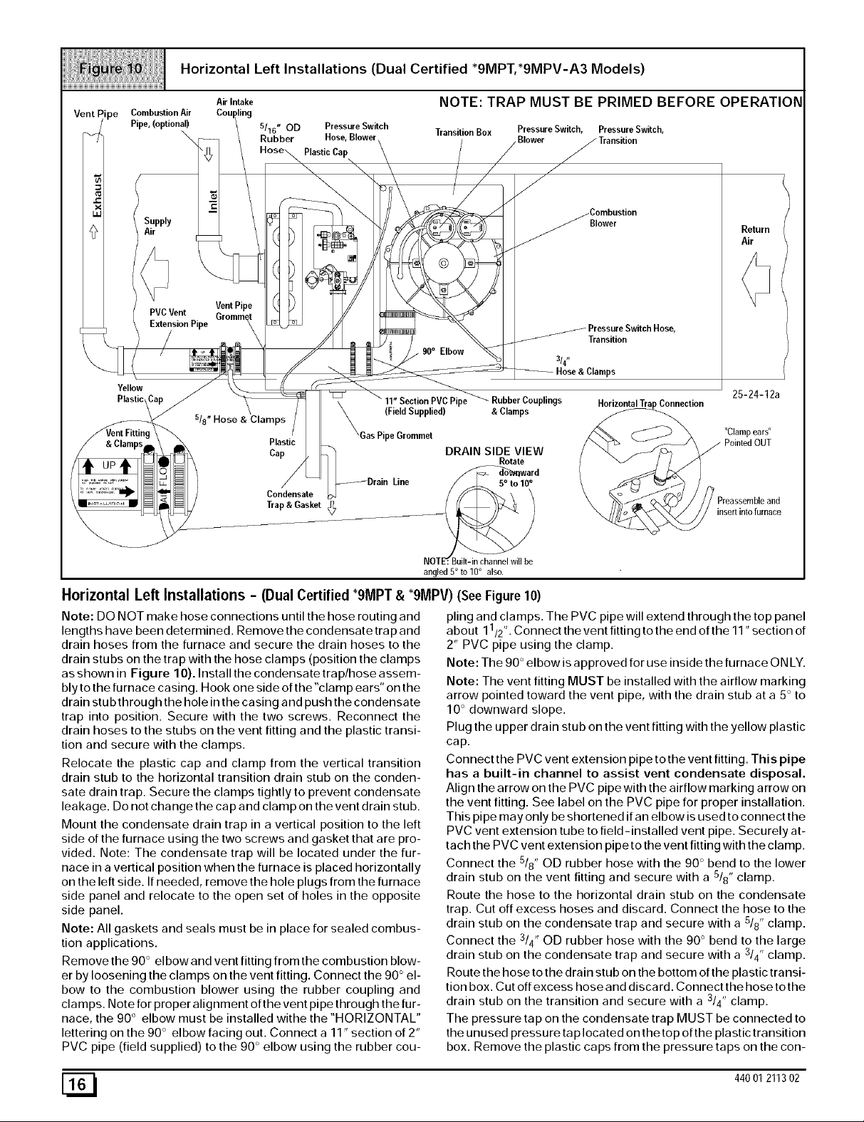
HorizontalLeftInstallations (Dual Certified *9MPT,*9MPV-A3 Models)
Combustion Air
Pipe, (optional)
Supply
Air
PVCVent Grommet
ExtensionPipe
Yellow
Plastic
Air Intake
5/'16" OD Pressure Switch
Rubber Hose, Blower
VentPipe
518" Hose & Clamps
Plastic Cap
Plastic
Cap
Condensate
Trap & Gasket
NOTE: TRAP MUST BE PRIMED BEFORE OPERATION
Transition Box Pressure Switch, Pressure Switch,
Elbow
(Field Supplied) & Clamps
ipe plings
DRAIN SIDE VIEW
Rotate
Blower
ward
Blower
Transition
314"
Hose & Clamps
Connection
Return
Air
25-24-12a
"Clamp ears"
_ Preassembleand
insertinto furnace
angled5° to10° also.
Horizontal Left Installations - (Dual Certified "9MPT & "9MPV) (See Figure 10)
Note: DO NOT make hose connections until the hose routing and
lengths have been determined. Remove the condensate trap and
drain hoses from the furnace and secure the drain hoses to the
drain stubs on the trap with the hose clamps (position the clamps
as shown in Figure 10). Install the condensate trap/hose assem-
bly to the furnace casing. Hook one side of the "clamp ears" on the
drain stubthrough the hole in the casing and push the condensate
trap into position. Secure with the two screws. Reconnect the
drain hoses to the stubs on the vent fitting and the plastic transi-
tion and secure with the clamps.
Relocate the plastic cap and clamp from the vertical transition
drain stub to the horizontal transition drain stub on the conden-
sate drain trap. Secure the clamps tightly to prevent condensate
leakage. Do not change the cap and clamp on the vent drain stub.
Mount the condensate drain trap in a vertical position to the left
side of the furnace using the two screws and gasket that are pro-
vided. Note: The condensate trap will be located under the fur-
nace in a vertical position when the furnace is placed horizontally
on the left side. If needed, remove the hole plugs from the furnace
side panel and relocate to the open set of holes in the opposite
side panel.
Note: All gaskets and seals must be in place for sealed combus-
tion applications.
Remove the 90 ° el bow and vent fitting from the combustion blow-
er by loosening the clamps on the vent fitting. Connect the 90 ° el-
bow to the combustion blower using the rubber coupling and
cla raps. Note for proper alignment of the vent pipe through the fur-
nace, the 90 ° elbow must be installed withe the "HORIZONTAL"
lettering on the 90 ° elbow facing out. Connect a 11" section of 2"
PVC pipe (field supplied) to the 90 ° elbow using the rubber cou-
piing and clamps. The PVC pipe will extend through the top panel
1 ,
about 1 /2' •Connect the vent fitting to the end of the 11' section of
2" PVC pipe using the clamp.
Note: The 90 ° elbow is approved for use inside the furnace ON LY.
Note: The vent fitting MUST be installed with the airflow marking
arrow pointed toward the vent pipe, with the drain stub at a 5° to
10 ° downward slope.
Plug the upper drain stub on the vent fitting with the yellow plastic
cap.
Connect the PVC vent extension pipe to the vent fitting. This pipe
has a built-in channel to assist vent condensate disposal.
Align the arrow on the PVC pipe with the airflow marking arrow on
the vent fitting. See label on the PVC pipe for proper installation.
This pipe may only be shortened if an elbow is used to connect the
PVC vent extension tube to field-installed vent pipe. Securely at-
tach the PVC vent extension pipe to the vent fitting with the clamp.
Connect the 5/8" OD rubber hose with the 90 ° bend to the lower
drain stub on the vent fitting and secure with a 5/8" clamp.
Route the hose to the horizontal drain stub on the condensate
trap. Cut off excess hoses and discard. Connect the hose to the
drain stub on the condensate trap and secure with a 5/8" clamp.
Connect the 3/4" OD rubber hose with the 90 ° bend to the large
drain stub on the condensate trap and secure with a 3/4" clamp.
Route the hose to the drain stub on the bottom of the plastic tra nsi-
tion box. Cut off excess hose and discard. Connect the hose to the
drain stub on the transition and secure with a 3/4" clamp.
The pressure tap on the condensate trap MUST be connected to
the unused pressure tap located on the top of the plastic transition
box. Remove the plastic caps from the pressure taps on the con-
[_ 44001211302
densatetrap and the plastic transition and connect with the 5/16"
OD rubber hose.
Note: This will require drilling a 5/16" OD hole in the furnace cas-
ing next to the condensate trap.
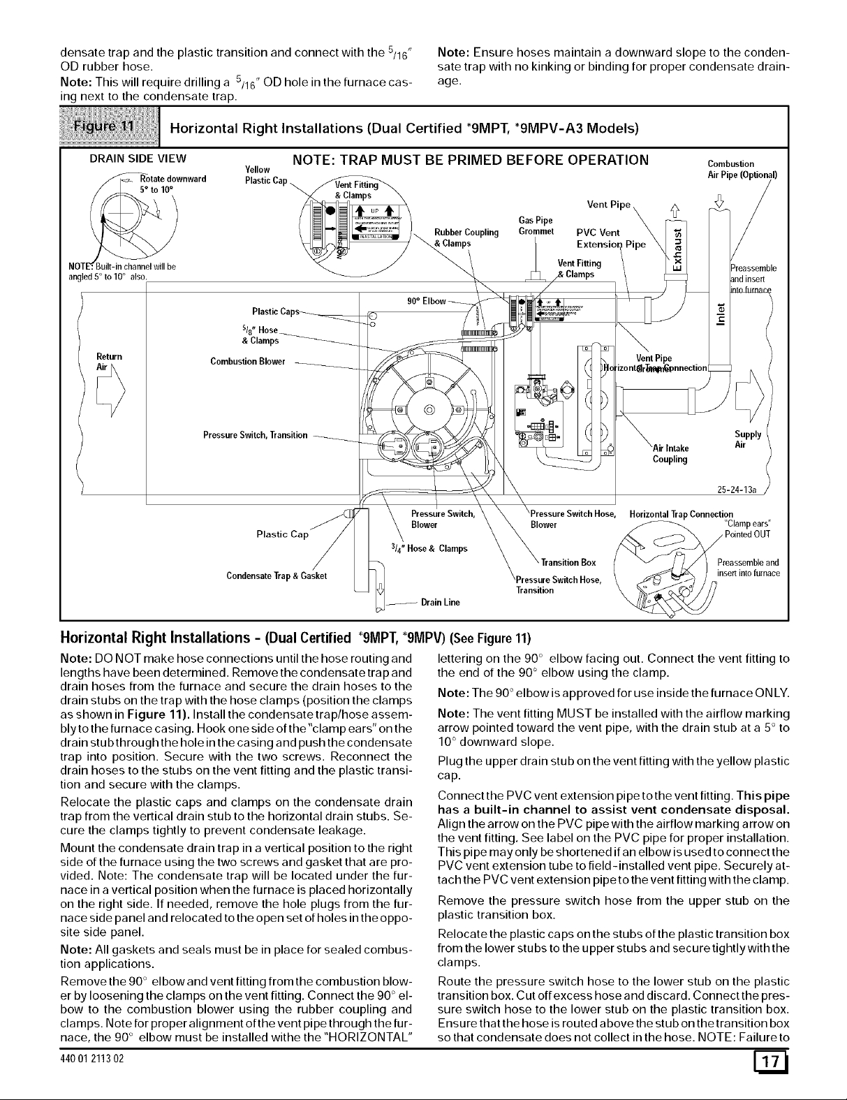
Horizontal Right Installations (Dual Certified *9MPT, *9MPV-A3 Models)
Note: Ensure hoses maintain a downward slope to the conden-
sate trap with no kinking or binding for proper condensate drain-
age.
DRAIN SIDE VIEW
//_Rotate downward
NOTE:_
angled 5° to 10° also.
Return
NOTE: TRAP MUST BE PRIMED BEFORE OPERATION Combustion
YellowPlastic AirPipe
Cap
& Clamps
Combustion Blower
Pressure Switch, Transition
Plastic Cap
Condensate Trap & Gasket
/ _ /_ Rubber Coupling Grommet PVC Vent
ps Vent Fitting Preassemble
PressureSwitch, HorizontalTrapConnection
Blower Blower "Clampears"
314"Hose & Clamps
DrainLine
Gas Pipe
Transition
Vent Pi z_
Intake
Coupling
Supply
Air
25-24-13a
Preassemble and
insert inlo furnace
Horizontal Right Installations - (Dual Certified "9MPT, "9MPV) (See Figure 11)
Note: DO NOT make hose connections until the hose routing and
lengths have been determined. Remove the condensate trap and
drain hoses from the furnace and secure the drain hoses to the
drain stubs on the trap with the hose clamps (position the clamps
as shown in Figure 11). Install the condensate trap/hose assem-
bly to the furnace casing. Hook one side of the "clamp ears" on the
drain stub through the hole in the casing and push the condensate
trap into position. Secure with the two screws. Reconnect the
drain hoses to the stubs on the vent fitting and the plastic transi-
tion and secure with the clamps.
Relocate the plastic caps and clamps on the condensate drain
trap from the vertical drain stub to the horizontal drain stubs. Se-
cure the clamps tightly to prevent condensate leakage.
Mount the condensate drain trap in a vertical position to the right
side of the furnace using the two screws and gasket that are pro-
vided. Note: The condensate trap will be located under the fur-
nace in a vertical position when the furnace is placed horizontally
on the right side. If needed, remove the hole plugs from the fur-
nace side panel and relocated to the open set of holes in the oppo-
site side panel.
Note: All gaskets and seals must be in place for sealed combus-
tion applications.
Remove the 90 ° el bow and vent fitting from the combustion blow-
er by loosening the clamps on the vent fitting. Connect the 90 ° el-
bow to the combustion blower using the rubber coupling and
cla raps. Note for proper alignment of the vent pipe through the fur-
nace, the 90 ° elbow must be installed withe the "HORIZONTAL"
44001 211302
lettering on the 90 ° elbow facing out. Connect the vent fitting to
the end of the 90 ° elbow using the clamp.
Note: The 90 ° elbow is approved for use inside the furnace ON LY.
Note: The vent fitting MUST be installed with the airflow marking
arrow pointed toward the vent pipe, with the drain stub at a 5° to
10 ° downward slope.
Plug the upper drain stub on the vent fitting with the yellow plastic
cap.
Connect the PVC vent extension pipe to the vent fitting. This pipe
has a built-in channel to assist vent condensate disposal.
Align the arrow on the PVC pipe with the airflow marking arrow on
the vent fitting. See label on the PVC pipe for proper installation.
This pipe may only be shortened if an elbow is used to connect the
PVC vent extension tube to field-installed vent pipe. Securely at-
tach the PVC vent extension pipe to the vent fitting with the clamp.
Remove the pressure switch hose from the upper stub on the
plastic transition box.
Relocate the plastic caps on the stubs of the plastic transition box
from the lower stubs to the upper stubs and secure tightly with the
clamps.
Route the pressure switch hose to the lower stub on the plastic
transition box. Cut off excess hose and discard. Connect the pres-
sure switch hose to the lower stub on the plastic transition box.
Ensure that the hose is routed above the stub on the transition box
so that condensate does not collect in the hose. NOTE: Failure to
correctlyinstallthepressureswitchhosetothetransitioncanad-
verselyaffectthe safety control operation.
Connect the 3/4" OD rubber hose with the 90 ° bend to the large
drain stub on the condensate trap and secure with a 3/4" clamp.
Route the hose to the drain stub on the bottom of the plastic tran-
sition box. Cut off excess hose and discard. Connect the hose to
the drain stub on the transition and secure with a 3/4" clamp.
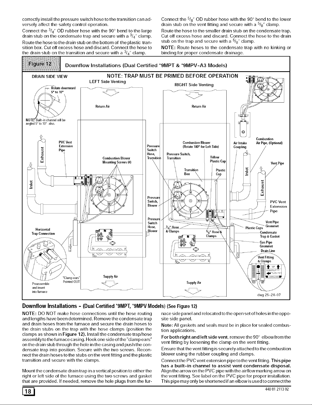
Downflow Installations (Dual Certified *9MPT & *9MPV-A3 Models)
Connect the 5/8" OD rubber hose with the 90 ° bend to the lower
drain stub on the vent fitting and secure with a 5/8" clamp.
Route the hose to the smaller drain stub on the condensate trap.
Cut off excess hose and discard. Connect the hose to the drain
stub on the trap and secure with a 5/8" clamp.
NOTE: Route hoses to the condensate trap with no kinking or
binding for proper condensate drainage.
DRAIN SIDE VIEW
/_ate downward
NOTE_.Built-in channel will be
angled 5° to 10° also.
PVCVent
Extension
Horizontal
TrapConnection
NOTE: TRAP MUST BE PRIMED BEFORE OPERATION
LEFT Side Venting
ReturnAir
Combustion Blower
Mounting Screws (4)
Pressure
Switch
Hose,
Transitio
Pressurq
Switch,
Blower.
Pressur,
Switch
Hose,
Blower
]
RIGHT Side Venting
<Z>
Combustion Blower
(Rotate 180 ° for Left Side)
Pressure Switch,
Transition
Transition
Box
& Clamps
ReturnAir
Yellow
PlasticCap
Clamps
Air Intake
Coupling
Combustion
Air Pipe, (Optional)
PlasticCaps
PVC Vent
Extension
Pipe
Vent Pipe
Grommet
Condensate
Trap & Gasket
Gas Pipe
Grommet
Brain Line
SupplyAir
Preassemble
and insert
into furnace
<Z>
SupplyAir
<Z>
dwg 25-24-07
Downflow Installations - (Dual Certified *9MPT,*9MPV Models) (See Figure 12)
NOTE: DO NOT make hose connections until the hose routing
and lengths have been determined. Remove the condensate trap
and drain hoses from the furnace and secure the drain hoses to
the drain stubs on the trap with the hose clamps (position the
clamps as shown in Figure 12). Install the condensate trap/hose
assembly to the furnace casing. Hook one side of the"clamp ears"
on the drain stub through the hole in the casing and push the con-
densate trap into position. Secure with the two screws. Recon-
nect the drain hoses to the stubs on the vent fitting and the plastic
transition and secure with the clamps.
Mount the condensate drain trap in a vertical position to either the
right or left side of the furnace using the two screws and gasket
that are provided. If needed, remove the hole plugs from the fur-
[_ 44001211302
nace side panel and relocated to the open set of holes in the oppo-
site side panel.
Note: All gaskets and seals must be in place for sealed combus-
tion applications.
For both right and left side vent, remove the 90 ° elbow from the
vent fitting by loosening the clamp on the vent fitting.
Ensure that the vent fitting is securely attached to the combustion
blower using the rubber coupling and clamps.
Connect the PVC vent extension pipe to the vent fitting. This pipe
has a built-in channel to assist vent condensate disposal.
Align the arrow on the PVC pipe with the airflow marking arrow on
the vent fitting. See label on the PVC pipe for proper installation.
This pipe may only be shortened if an elbow is used to connect the
 Loading...