


C9MPD050F12C1
ICP C9MPD050F12C1, C9MPD075F12C1, C9MPD080J16C1, C9MPD100J14C1, C9MPD100J20C1 Installation Guide
...
90 SingleStage
CategoryIVFurnace
N9MP1 & N9MP2
*9MPD *Denotes Brands (C, H, T)
FANASSISTED,DIRECTOR
NON-DIRECTVENTGASFURNACE
SAFETY REQUIREMENTS
Recognize safety information. This is the safety- alert symbolZ_. When you see this symbol on the furnace and in instructions manuals be alert to
the potential for personal injury.
Understand the signal words DANGER, WARNING, or CAUTION. These words are used with the safety-alert symbol. DANGER identifies the
most serious hazards, those that will result in severe personal injury or death. WARNING signifies a hazard that could result in personal injury or
death. CAUTIONis used to identify unsafe practices that could result in minor personal injury or product and property damage. Note is used to
highlight suggestions that will result in enhanced installation, reliability, or operation.
Installing and servicing heating equipment can be hazardous due to gas and electrical components. Only trained and qualified personnel should
install, repair, or service heating equipment.
Untrained service personnel can perform basic maintenance functions such as cleaning and replacing air filters. All other operations must be
performed by trained service personnel. When working on heating equipment, observe precautions in the literature, on tags, and on labels attached
to or shipped with the unit and other safety precautions that may apply.
Follow all safety codes. In the United States, follow all safety codes including the current edition National Fuel Gas Code (NFGC) ANSI
Z223.1-2002/NFPA No. 54-2002. In Canada, refer tothecurrent edition of the National Standard of Canada Natural Gas and Propane Installation
Code (NSCNGPIC) CSA B149.1-05. Wear safety glasses and work gloves. Have fire extinguisher available during start-up and adjustment
procedures and service calls.
These instructions cover minimum requirements and conform to existing national standards and safety codes. In some instances, these instructions
exceed certain local codes and ordinances, especially those that may not have kept up with changing residential construction practices. We require
these instructions as a minimum for a safe installation.
International Comfort Products, LLC
Lewisburg, TN 37091 U.S.A.
Table of Contents
INSTALLER: Affix these instructions
on or adjacent to the furnace.
CONSUMER: Retain these
instructions for future reference.
1.SafeInstallationRequirements................. 3
2.Installation ................................ 4
3.Combustion & Ventilation Air .................. 8
4.Vent & Combustion Air Piping ................ 12
5.GasSupply and Piping ...................... 30
6.Electrical Wiring ........................... 37
7. Ductwork and Filter ........................ 37
8. Checks and Adjustments .................... 39
9. Furnace Maintenance ....................... 42
10. Sequence of Operation & Diagnostics .......... 44
11. Concentric Vent Termination ................. 45
Tech Support and Parts ........................ 47
ELECTRIC SHOCK HAZARD
Failure to follow safety
warnings exactly could result
in serious injury and/or death.
Turn Off All Power Before
Servicing.
CARBON MONOXIDE POISONING AND FIRE
HAZARD.
Failure to follow safety warnings exactly could
result in serious injury, death, and/or property
damage.
This furnace is not designed for use in mobile
homes, trailers or recreational vehicles.
PrintedinU.S.A. 11/28/2005 440 01 1021 (02)
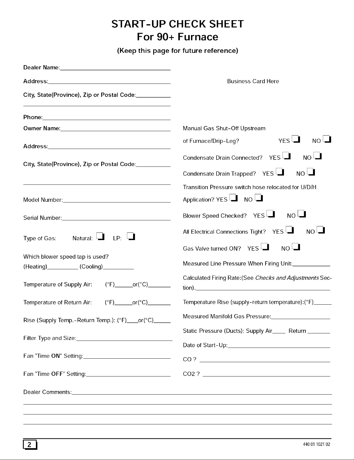
START-UP CHECK SHEET
For 90+ Furnace
(Keep this page for future reference)
Dealer Name:
Address:
City, State(Province), Zip or Postal Code:
Business Card Here
Phone:
Owner Name:
Address:
City, State(Province), Zip or Postal Code:
Model Number:
Serial Number:
Type of Gas: Natural: [_ LP: [_
Which blower speed tap is used?
(Heating) (Cooling).
Temperature of Supply Air: (°F) or(°C)
Temperature of Return Air: (°F)__.or(°C).
Rise (Supply Temp.-Return Temp.): (°F) or(°C)__
Filter Type and Size:
Fan "Time ON" Setting:.
Fan "Time OFF" Setting:
Manual Gas Shut-Off Upstream
of Furnace/Drip- Leg?
Condensate Drain Connected?
YES [_
YES [_
Condensate Drain Trapped? YES [_
NOE_I
NO
NO
Transition Pressure switch hose relocated for U/D/H
Application? YES [_ NO [_
Blower Speed Checked? YES [_ NO [_
All Electrical Connections Tight? YES [_
Gas Valve turned ON? YES [_ NO [_
NOE_I
Measured Line Pressure When Firing Unit:
Calculated Firing Rate:(See Checks and Adjustments Sec-
tion).
Temperature Rise (supply-return temperature):(°F)__
Measured Manifold Gas Pressure:
Static Pressure (Ducts): Supply Air Return
Date of Start-Up:
CO?
CO2 ?
Dealer Comments:
E_ 44001102102
1. Safe Installation Requirements
FIRE, EXPLOSION, AND ASPHIXIATION HAZARD
Improper adjustment, alteration, service,
maintanence or installation could cause death,
personal injury and/or property damage.
Installation or repairs made by unqualified persons
could result in hazards to you and others.
Installation MUST conform with local codes or, in
the absence of local codes, with codes of all
governmental authorities havingjurisdiction.
The information contained in this manual is
intended for use by a qualified service agency that
is experienced in such work, is familiar with all
precautions and safety procedures required in
such work, and is equipped with the proper tools
and test instruments.
• This furnace is NOT approved for installation in mo-
bile homes, trailers or recreation vehicles.
• Seal around supply and return air ducts.
• Install correct filter type and size.
• Unit MUST be installed so electrical components are pro-
tected from direct contact with water.
Safety Rules
Your unit is built to provide many years of safe and dependable
service providing it is properly installed and maintained. However,
abuse and/or improper use can shorten the life of the unit and
create hazards for you, the owner.
A,
The U.S. Consumer Product Safety Commission encourages
installation of carbon monoxide alarms. There can be various
sources of carbon monoxide in a building or dwelling. The
sources could be gas-fired clothes dryers, gas cooking
stoves, water heaters, furnaces, gas-fired fireplaces, wood
fireplaces.
NOTE: This furnace is design-certified by the CSA International
(formerly AGA and CGA) for installation in the United States and
Canada. Refer to the appropriate codes, along with this manual,
for proper installation.
Use only the Type of gas approved for this furnace (see
Rating Plate on unit). Overfiring will result in failure of heat
exchanger and cause dangerous operation. (Furnaces
can be converted to L.R gas with approved kit.)
Install this furnace only in a location and position as speci-
fied in "2. Installation"of these instructions.
• Provide adequate combustion and ventilation air to the fur-
nace as specified in "3. Combustion and Ventilation Air" of
these instructions.
Carbon monoxide can cause serious bodily injury and/or
death. Carbon monoxide or "CO" is a colorless and odorless
gas produced when fuel is not burned completely or when the
flame does not receive sufficient oxygen.
Therefore, to help alert people of potentially dangerous ca rbon
monoxide levels, you should have a commercially available
carbon monoxide alarm that is listed by a nationally recog-
nized testing agency in accordance with Underwriters Labora-
tories Inc. Standard for Single and Multiple Station Carbon
Monoxide Alarms, ANSI/UL 2034 or the CSA 6.19-01 Resi-
dential Carbon Alarming Devices installed and maintained in
the building or dwelling concurrently with the gas- fired furnace
installation (see Note below). The alarm should be installed as
recommended by the alarm manufacturer's installation in-
structions.
Combustion products must be discharged outdoors. Con-
nect this furnace to an approved vent system only, as spe-
cified in "4. Vent and Combustion Air Piping" of these
instructions.
Never test for gas leaks with an open flame. Use a com-
mercially available soap solution made specifically for the
detection of leaks to check all connections, as specified in
"6. Gas Supply and Piping, Final Check"of these instruc-
tions.
Always install furnace to operate within the furnace's in-
tended temperature-rise range with a duct system which
has an external static pressure within the allowable range,
as specified in "Technical Support Manual" of these in-
structions. See furnace rating plate.
When a furnace is installed so that supply ducts carry air
circulated by the furnace to areas outside the space con-
taining the furnace, the return air shall also be handled by a
duct(s) sealed to the furnace casing and terminating out-
side the space containing the furnace.
A gas-fired furnace for installation in a residential garage
must be installed as specified in "2. Installation"of these
instructions.
44001 102102
This furnace is not to be used for temporary heating of
buildinq.s or structures under construction.
B,
There can be numerous sources of fire or smoke in a building
or dwelling. Fire or smoke can cause serious bodily injury,
death, and/or property damage. Therefore, in order to alert
people of potentially dangerous fire or smoke, you should have
fire extinguisher and smoke alarms listed by Underwriters Lab-
oratories installed and maintained in the building or dwelling
(see Note below).
Note: The manufacturer of your furnace does not test any alarms
and makes no representations regarding any brand or type
of alarms.
C. To ensure safe and efficient operation of your unit, you should
do the following:
1. Thoroughly read this manual and labels on the unit. This
will help you understand howyour unit operates and the haz-
ards involved with gas and electricity.
Do not use this unit if any part has been under water. Im-
mediately call a qualified service technician to inspect the unit
and to replace any part of the control system and any gas con-
trol which has been under water.
Never obstruct the vent grilles, or any ducts that provide
air to the unit. Air must be provided for proper combustion
and ventilation of flue gases.
C21
FrozenWater PipeHazard
WATER DAMAGE TO PROPERTY HAZARD
Failure to protect against the risk of freezing may
result in property damage.
Do not leave your home unattended for long periods
during freezing weather without turning off water
supply and draining water pipes or otherwise
protecting against the risk of frozen pipes and
resultant damage.
Your furnace is designed solely to provide a safe and comfortable
living environment. The furnace is NOT designed to ensure that
water pipes will not freeze. It is equipped with several safety de-
vices that are designed to turn the furnace off and prevent it from
restarting in the event of various potentially unsafe conditions.
If your furnace remains off for an extended time, the pipes in your
home could freeze and burst, resulting in serious water damage.
If the structure will be unattended during cold weather you should
take these precautions.
1. Turn off the water supply to the structure and drain the water
lines if possible and add an antifreeze for potable water to
drain traps and toilet tanks. Open faucets in appropriate
areas.
-or-
2. Installation
Have someone check the structure frequently during cold
weather to make sure it is warm enough to prevent pipes
from freezing. Instruct them on a service agency to call to
provide service, if required.
-or-
3. Install a reliable remote sensing device that will notify some-
body of freezing conditions within the home.
Winter Shutdown
If you go away during the winter months and do not leave the heat
on in your home, the plastic transition box and the condensate trap
on the furnace must be protected from freeze damage.(See
Figure 10 trough Figure 19)
1. Disconnect the 5/8" OD rubber hose from the vent drain fit-
ting that is located downstream of the combustion blower.
Insert a funnel into the hose and pour four(4) ounces of sani-
tary type (RV) antifreeze into the condensate trap. Recon-
nect the 5/8" OD rubber hose to the stub on the vent drain
fitting. Secure with the hose clamp.
2. Disconnect the 3/4" OD rubber hose from the condensate
trap. Insert a funnel into the hose and and pour four(4)
ounces of sanitary type (RV) antifreeze into the plastic Tran-
sition box. Squeeze the hose together near the end and
quickly reconnect the 3/4" OD rubber hose to the stub on the
condensate trap. Secure with the hose clamp.
When you return home, your furnace will be ready to start, as it is
not necessary to drain the antifreeze from the furnace.
CARBON MONOXIDE POISONING HAZARD
Failure to properly vent this furnace or other
appliances could result in death or personal injury.
This furnace can NOT be common vented or
connected to any type B, BW or L vent or vent
connector, nor to any portion of a factory-built or
masonry chimney. If this furnace is replacing a
3reviously common-vented furnace, it may be
necessary to resize the existing vent and chimney to
3revent oversizing problems for the other
remaining appliance(s). See Venting and Combus-
tion Air Check in Gas Vent Installation section. This
furnace MUST be vented to the outside.
Location and Clearances
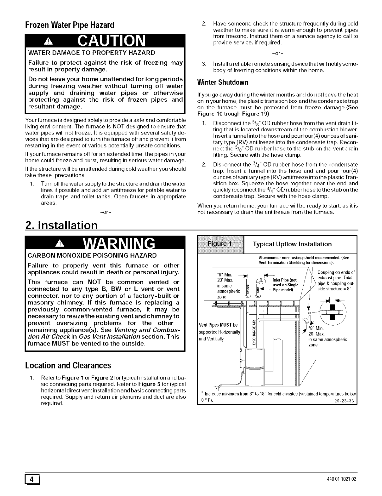
1,
Refer to Figure 1 or Figure 2 for typical installation and ba-
sic connecting parts required. Refer to Figure 5 for typical
horizontal direct vent installation and basic connecting parts
required. Supply and return air plenums and duct are also
required.
Typical Upflow Installation
Aluminum or non-rusting shield recommended. (See
Vent Termination Shielding for dimensions).
8" Min. _1 _[_nlet
20Max
Pipe(not
in same _ _ used on Single
atmospheric Pipe model)
zone
Vent PipesMUSTbe
supportedHorizonta]l
andVertically
Couplingon endsof
exhaust pipe.Total
_pipe &couplingout-
' in.
_atmosphedc'ax.
* Increase minimum from 8" to 18" for cold climates (sustained temperatures below
0 ° F). 25-23-33
E_I 44001 102102
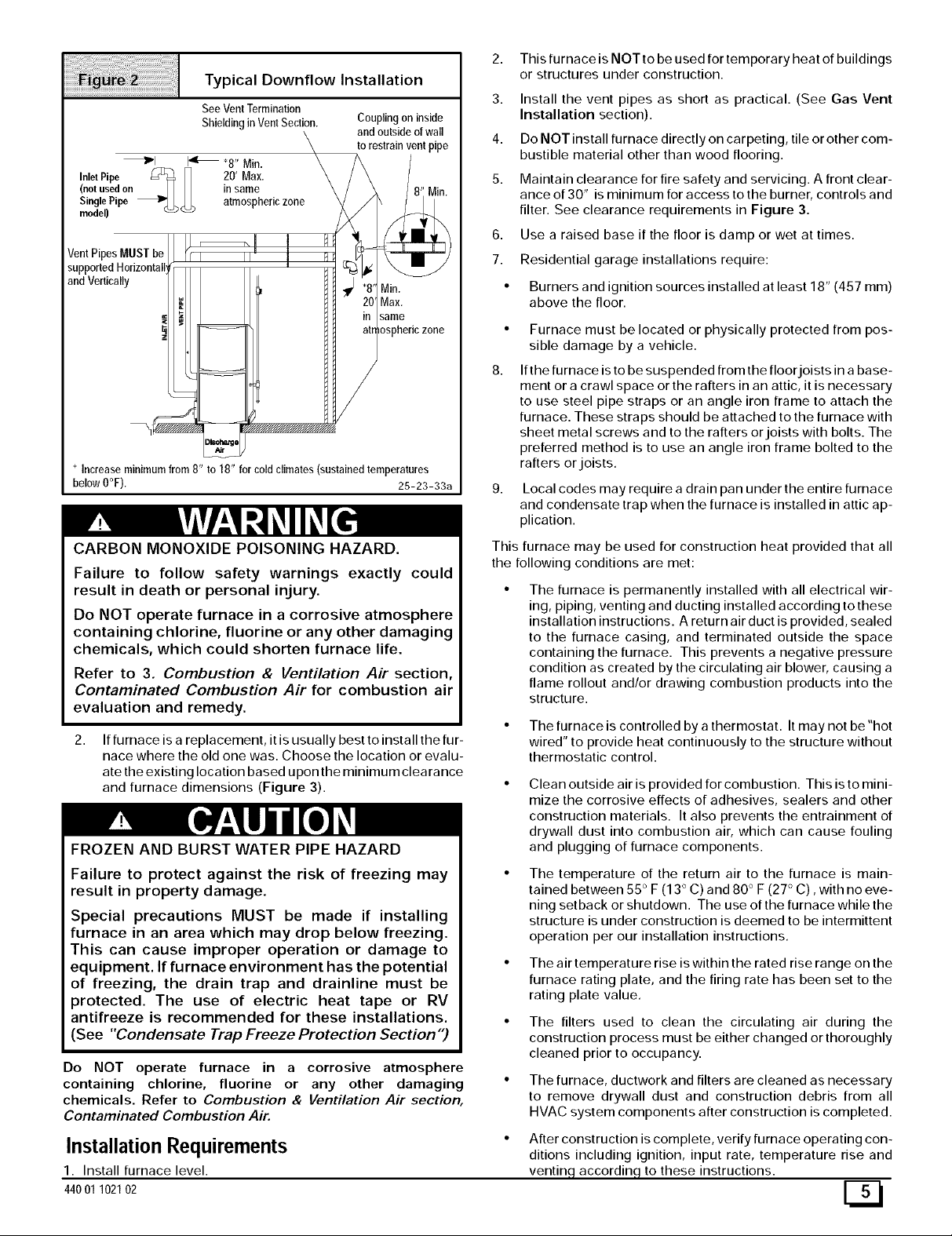
TypicalDownflowInstallation
See VentTermination
Shieldingin VentSection.
_1 14' *8" Min.
InletPipe _ I] 20' Max.
(not usedon _ in same
SinglePipe _ I,,,J I,, atmospheric zone
model) _ '_'
Vent Pip MUST bq
support_ 4orizonte
andVertically
Coupling on inside
and outside of wall
to restrain vent pipe
Min.
Max.
same
osphericzone
Increase minimum from 8" to 18" for cold climates (sustained temperatures
below 0°F). 25-23-33a
CARBON MONOXIDE POISONING HAZARD.
Failure to follow safety warnings exactly could
result in death or personal injury.
Do NOT operate furnace in a corrosive atmosphere
containing chlorine, fluorine or any other damaging
chemicals, which could shorten furnace life.
Refer to 3. Combustion & Ventilation Air section,
Contaminated Combustion Air for combustion air
evaluation and remedy.
2,
If furnace is a replacement, it is usually best to install the fur-
nace where the old one was. Choose the location or evalu-
ate the existing location based upon the minimum clearance
and furnace dimensions (Figure 3).
FROZEN AND BURST WATER PIPE HAZARD
Failure to protect against the risk of freezing may
result in property damage.
Special precautions MUST be made if installing
furnace in an area which may drop below freezing.
This can cause improper operation or damage to
equipment. If furnace environment has the potential
of freezing, the drain trap and drainline must be
protected. The use of electric heat tape or RV
antifreeze is recommended for these installations.
(See "Condensate Trap Freeze Protection Section")
Do NOT operate furnace in a corrosive atmosphere
containing chlorine, fluorine or any other damaging
chemicals. Refer to Combustion & Ventilation Air section,
Contaminated Combustion Air.
Installation Requirements
1. Install furnace level.
44001 102102
2. This furnace is NOT to be used for temporary heat of buildings
or structures under construction.
3. Install the vent pipes as short as practical. (See Gas Vent
Installation section).
4. Do NOT install furnace directly on carpeting, tile or other com-
bustible material other than wood flooring.
5. Maintain clearance for fire safety and servicing. A front clear-
ance of 30" is minimum for access to the burner, controls and
filter. See clearance requirements in Figure 3.
6. Use a raised base if the floor is damp or wet at times.
7. Residential garage installations require:
• Burners and ignition sources installed at least 18" (457 ram)
above the floor.
8.
Furnace must be located or physically protected from pos-
sible damage by a vehicle.
If the furnace is to be suspended from the floor joists in a base-
ment or a crawl space or the rafters in an attic, it is necessary
to use steel pipe straps or an angle iron frame to attach the
furnace. These straps should be attached to the furnace with
sheet metal screws and to the rafters or joists with bolts. The
preferred method is to use an angle iron frame bolted to the
rafters or joists.
Local codes may require a drain pan under the entire furnace
and condensate trap when the furnace is installed in attic ap-
plication.
This furnace may be used for construction heat provided that all
the following conditions are met:
The furnace is permanently installed with all electrical wir-
ing, piping, venting and ducting installed according to these
installation instructions. A return air duct is provided, sealed
to the furnace casing, and terminated outside the space
containing the furnace. This prevents a negative pressure
condition as created by the circulating air blower, causing a
flame rollout and/or drawing combustion products into the
structure.
• The furnace is controlled by a thermostat. It may not be "hot
wired" to provide heat continuously to the structure without
thermostatic control.
Clean outside air is provided for combustion. This is to mini-
mize the corrosive effects of adhesives, sealers and other
construction materials. It also prevents the entrainment of
drywall dust into combustion air, which can cause fouling
and plugging of furnace components.
The temperature of the return air to the furnace is main-
tained between 55 ° F (13 ° C) and 80 ° F (27 ° C), with no eve-
ning setback or shutdown. The use of the furnace while the
structure is under construction is deemed to be intermittent
operation per our installation instructions.
The air temperature rise is within the rated rise range on the
furnace rating plate, and the firing rate has been set to the
rating plate value.
The filters used to clean the circulating air during the
construction process must be either changed or thoroughly
cleaned prior to occupancy.
The furnace, ductwork and filters are cleaned as necessary
to remove drywall dust and construction debris from all
HVAC system components after construction is completed.
After construction is complete, verify furnace operating con-
ditions including ignition, input rate, temperature rise and
venting, accordinq to these instructions.

Dimensions & Clearances
?
F
TOP
_qE --
LEFT SIDE
TRAP (KO)(COUNTERELON)_
VENT_
AIRINTAKE (KO)
(ALTERNATE)
413116_
TRAP (KO)
UPFLOW/HORIZONTAL
• THERMOSTAT/_ 7--(KO)
_=_/ 215/8 47/8
17/8 24
BOTTOM
Unit
Capacity
N9MP1050B12
N9MPlO75B12
N9MP1080F16
N9MP1100F14
N9MPllOOJ20
N9MPl125J20
N9MP2050B12
N9MP2075B12
N9MP2080F16
N9MP2100F14
N9MP2100J20
N9MP2125J20
*9MPD050F12
*9MPD075F12
*9MPDO80J16
*9MPDlOOJ14
*9MPDIOOJ20
*9MPD125L20
23118
Cabinet Boffom
_O_G/AIR INTAKE
VENI (*9MPD)
_11/4
/ ELECTRICAL
11116
13/8 29_/8
24 _/4
175116
/16
t
_-_ 37/8
_A_
-- B--
FRONT
131116
16
1913/6
Drawing is representative,
but some models may vary
MINIMUM CLEARANCES TO
COMBUSTIBLE MATERIALS FOR ALL UNITS
REAR 0
FRONT (combustion air openings in 3"
furnace and in structure)
Required For Service '24"
ALL SIDES Of SUPPLY PLENUM 1"
SIDES 0
VENT 0
TOP OF FURNACE 1"
"30" clearancerecommendedforfurnaceremoval.
Horizontal position: Line contact is permissible only between
lines formed by intersections of top and two sides of furnace
jacket, and building joists, studs or framing.
NOTE: Evaporator "A" coil drain pan dimensions
may vary from furnace duct opening size. Always
consult evaporator specifications for duct size
requirements.
Furnace is designed for bottom return or side
return,
Return air through back of furnace is NOT allowed.
/
ALL DIMENSIONS IN INCHES
2
_P 11/16_
GAS (KO)
KO = KnockOut
1:
9
28112
-- 18112
RIGHT SIDE
, TRAP (KO) (COUNTERFLOW)
ELECTRICAL(KO)
AIRINTAKE(KO)
(ALTERNATE)
VENT(KO)
TRAP(KO)
UPFLOWtHORIZONTAL
21/4
THERMOSTAT l
191/4
1718
25-23-36b
Dentoes Brand
E_ 44001 102102
Knock Outs
CUT HAZARD
Failure to follow this caution may result in personal
injury.
Sheet metal parts may have sharp edges or burrs.
Use care and wear appropriate clothing, safety
glasses and gloves when handling parts and
servicing furnaces.
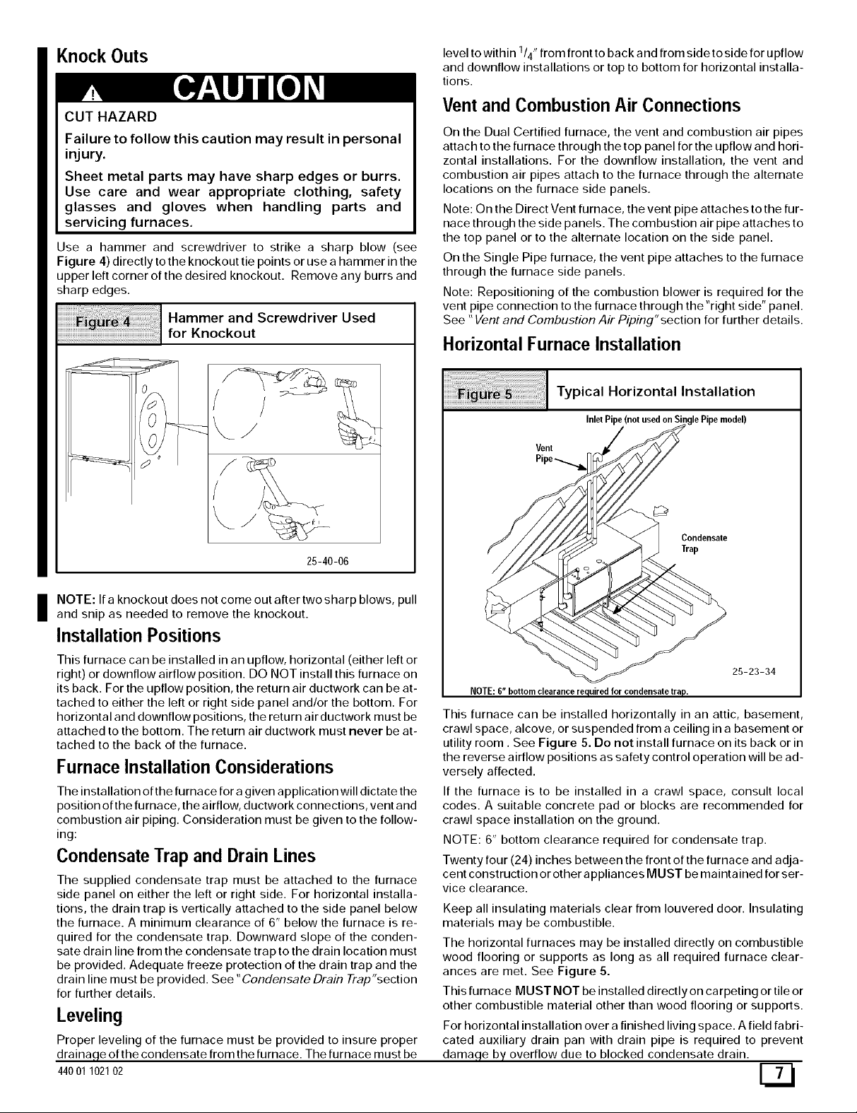
Use a hammer and screwdriver to strike a sharp blow (see
Figure 4) directly to the knockout tie points or use a hammer in the
upper left corner of the desired knockout. Remove any burrs and
sharp edges.
Hammer and Screwdriver Used
for Knockout
/
25-40-06
I OTE: If a knockout does not come out after two sharp blows, pull
and snip as needed to remove the knockout.
Installation Positions
This furnace can be installed in an upflow, horizontal (either left or
right) or downflow airflow position. DO NOT install this furnace on
its back. For the upflow position, the return air ductwork can be at-
tached to either the left or right side panel and/or the bottom. For
horizontal and downflow positions, the return air ductwork must be
attached to the bottom. The return air ductwork must never be at-
tached to the back of the furnace.
Furnace Installation Considerations
The installation of the furnace for a given application will dictate the
position of the furnace, the airflow, ductwork connections, vent and
combustion air piping. Consideration must be given to the follow-
ing:
Condensate Trap and Drain Lines
The supplied condensate trap must be attached to the furnace
side panel on either the left or right side. For horizontal installa-
tions, the drain trap is vertically attached to the side panel below
the furnace. A minimum clearance of 6" below the furnace is re-
quired for the condensate trap. Downward slope of the conden-
sate drain line from the condensate trap to the drain location must
be provided. Adequate freeze protection of the drain trap and the
drain line must be provided. See "Condensate Drain Trap"section
for further details.
Leveling
Proper leveling of the furnace must be provided to insure proper
_e of the condensate from the furnace. The furnace must be
44001 102102
level to within 1/4" from front to back and from side to side for upflow
and downflow installations or top to bottom for horizontal installa-
tions.
Vent and Combustion Air Connections
On the Dual Certified furnace, the vent and combustion air pipes
attach to the furnace through the top panel for the upflow and hori-
zontal installations. For the downflow installation, the vent and
combustion air pipes attach to the furnace through the alternate
locations on the furnace side panels.
Note: On the Direct Vent furnace, the vent pipe attaches to the fur-
nace through the side panels. The combustion air pipe attaches to
the top panel or to the alternate location on the side panel.
On the Single Pipe furnace, the vent pipe attaches to the furnace
through the furnace side panels.
Note: Repositioning of the combustion blower is required for the
vent pipe connection to the furnace through the "right side" panel.
See "Vent and Combustion Air Piping"section for further details.
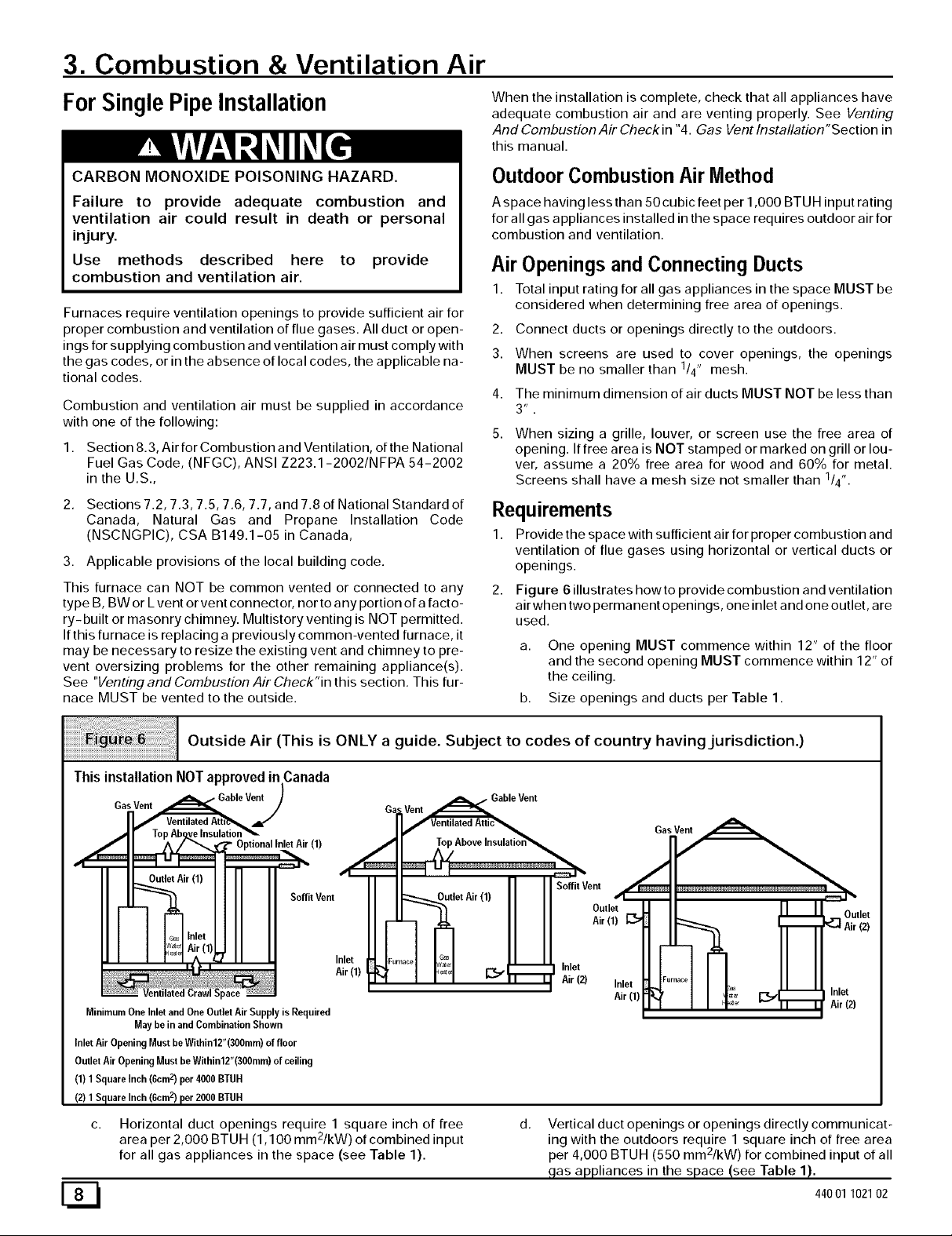
Horizontal Furnace Installation
Vent
Typical Horizontal Installation
Inlet Pipe (not used on Single Pipe model)
Condensate
Trap
25-23-34
NOTE: 6"bottomclearancerequiredfor condensatetrap.
This furnace can be installed horizontally in an attic, basement,
crawl space, alcove, or suspended from a ceiling in a basement or
utility room. See Figure 5. Do not install furnace on its back or in
the reverse airflow positions as safety control operation will be ad-
versely affected.
If the furnace is to be installed in a crawl space, consult local
codes. A suitable concrete pad or blocks are recommended for
crawl space installation on the ground.
NOTE: 6" bottom clearance required for condensate trap.
Twenty four (24) inches between the front of the furnace and adja-
cent construction or other appliances MUST be maintained for ser-
vice clearance.
Keep all insulating materials clear from Iouvered door. Insulating
materials may be combustible.
The horizontal furnaces may be installed directly on combustible
wood flooring or supports as long as all required furnace clear-
ances are met. See Figure 5.
This furnace MUST NOT be installed directly on carpeting or tile or
other combustible material other than wood flooring or supports.
For horizontal installation over a finished living space. A field fabri-
cated auxiliary drain pan with drain pipe is required to prevent
damn eq___ overflow due to blocked condensate drain.
3. Combustion & Ventilation Air
ForSingle PipeInstallation
When the installation is complete, check that all appliances have
adequate combustion air and are venting properly. See Venting
And Combustion Air Check in "4. Gas Vent Installation"Section in
this manual.
CARBON MONOXIDE POISONING HAZARD.
Failure to provide adequate combustion and
ventilation air could result in death or personal
injury.
Use methods described here to provide
combustion and ventilation air.
Furnaces require ventilation openings to provide sufficient air for
proper combustion and ventilation of flue gases. All duct or open-
ings for supplying combustion and ventilation air must comply with
the gas codes, or in the absence of local codes, the applicable na-
tional codes.
Combustion and ventilation air must be supplied in accordance
with one of the following:
1. Section 8.3, Air for Combustion and Ventilation, of the National
Fuel Gas Code, (NFGC), ANSI Z223.1-2002/NFPA 54-2002
in the U.S.,
2. Sections 7.2, 7.3, 7.5, 7.6, 7.7, and 7.8 of National Standard of
Canada, Natural Gas and Propane Installation Code
(NSCNGPIC), CSA B149.1-05 in Canada,
3. Applicable provisions of the local building code.
Outdoor Combustion Air Method
A space having less than 50 cubic feet per 1,000 BTUH input rating
for all gas appliances installed in the space requires outdoor air for
combustion and ventilation.
Air Openings and Connecting Ducts
1. Total input rating for all gas appliances in the space MUST be
considered when determining free area of openings.
2. Connect ducts or openings directly to the outdoors.
3. When screens are used to cover openings, the openings
MUST be no smaller than 1/4" mesh.
4. The minimum dimension of air ducts MUST NOT be less than
When sizing a grille, louver, or screen use the free area of
opening. If free area is NOT stamped or marked on grill or lou-
ver, assume a 20% free area for wood and 60% for metal.
Screens shall have a mesh size not smaller than 1/4".
Requirements
1. Provide the space with sufficient air for proper combustion and
ventilation of flue gases using horizontal or vertical ducts or
openings.
2. Figure 6 illustrates how to provide combustion and ventilation
air when two permanent openings, one inlet and one outlet, are
used.
This furnace can NOT be common vented or connected to any
type B, BW or Lvent or vent connector, nor to any portion of a facto-
ry- built or masonry chimney. Multistory venting is NOT permitted.
If this furnace is replacing a previously common-vented furnace, it
may be necessary to resize the existing vent and chimney to pre- a. One opening MUST commence within 12" of the floor
vent oversizing problems for the other remaining appliance(s), and the second opening MUST commence within 12" of
See "Venting and Combustion Air Check"in this section, This fur- the ceiling.
nace MUST be vented to the outside, b. Size openings and ducts per Table 1.
Outside Air (This is ONLY a guide. Subject to codes of country having jurisdiction.)
ThisinstallationNOTapprovedinCanada
GasVent
GableV_
(1)
Soffit Vent
Inlet
Air(1)
MinimumOne Inletand One Outlet Air Supply is Required
May be in andCombination Shown
Inlet Air OpeningMust beWithin12"(300mm)of floor
OutletAir OpeningMust be Within12"(300mm)of ceiling
(1) 1 SquareInch (6cm2) per 4000 BTUH
(2) 1 Square Inch(6cm2) per 2000 BTUH
G Vent _Gable
Vent
ual_ventilated Attic_
/11 _ TopAboveInsulatio_
I/ SoffitVent
I "etAi"l' Out,o,'=
II _ Air (1)
Furnace G_
_',, _ _ _ Inlet
"" Air (2) Inlet
Air(1)
ED
Horizontal duct openings require 1 square inch of free
a 2
rea per 2,000 BTUH (1,100 mm /kW) of combined input
for all gas appliances in the space (see Table 1).
d.
Vertical duct openings or openings directly communicat-
ing with the outdoors require 1 square inch of free area
e 2
p r 4,000 BTUH (550 mm /kW) for combined input of all
gas appliances in the space (see Table 1).
44001 102102

3. When one permanent outdoor opening is used, the opening
requires:
a. 1 sq. in of free area per 3,000 BTUH (700 mm2/kW) for
combined input of all gas appliances in the space (see
Table 1) and
b. not less than the sum of the areas of all vent connectors in
the space.
The opening shall commence within 12" of the top of the enclo-
sure. Appliances shall have clearances of at least 1" from the sides
and back and 6" from the front. The opening shall directly commu-
nicate with the outdoors or shall communicate through a vertical or
horizontal duct to the outdoors or spaces (crawl or attic) that freely
communicate with the outdoors.
4. Combination of Indoor and Outdoor Air shall have:
a.
b.
C.
Indoor openings that comply with the Indoor Combus-
tion Air Method below and
Outdoor openings located as required in the Outdoor
Combustion Air Method above and
Outdoor openings sized as follows.
1) Calculate the Ratio of all Indoor Space volume divid-
ed by required volume for Indoor Combustion Air Meth-
od.
2) Outdoor opening size reduction Factor is I minus the
Ratio in 1) above.
3) Minimum size of Outdoor openings shall be the size
required in Outdoor Combustion Air Method above
multiplied by reduction Factor.
Area
BTUH MinimumFree Area Requiredfor EachOpening or Ductto Outdoors
Input TwoHorizontalDucts SingleOpening TwoVerticalDuctsor Openings RoundDuct
Rating (sq. inJ2,000BTUH) (sq. in.i3,000BTUH) (sq. inJ4,000BTUH) (sq. in./4,000 BTUH)
50,000 25sq. in. 16.7sq. in. 12.8sq. in. 4"
75,000 37.5sq. in. 25sq. in. 1828 sq.in. 5"
80,000 40sq. in. 26.7sq. in. 20.0sq. in. 5"
100,000 80 sq. in. 33.3 sq.in. 25sq. in. 6"
125,000 62.50sq. in. 41.7sq. in. 31.25 sq. in. 7"
EXAMPLE: Determining Free Area
Furnace Water Heater
100,000 + 30,000
Furnace Water Heater
100,000 + 30,000
Indoor Combustion Air
Total Input
(130,000 + 4,000) 32.5 Sq. In. Vertical
Total Input
(130,000 + 2,000) 65 Sq. In. Horizontal
Standard and Known-Air-Infiltration Rate Methods
© NFPA&AGA
CARBON MONOXIDE POISONING HAZARD.
Failure to supply adequate combustion air could
result in death or personal injury.
Most homes will require additional air from
outdoors for combustion and ventilation. A space
with at least 50 cubic feet per 1,000 BTUH input
rating or homes with tight construction may need
outdoor air, supplied through ducts, to
supplement air infiltration for proper combustion
and ventilation of flue gases.
Indoor air is permitted for combustion and ventilation, if the Stan-
dard or Known-Air-Infiltration Rate Method is used.
The Standard Method may be used, if the space has no less vol-
ume than 50 cubic feet per 1,000 BTUH input rating for all gas ap-
pliances installed in the space. The standard method permits
indoor air to be used for combustion and ventilation air.
The Known Air Infiltration Rate Method shall be used if the in-
filtration rate is known to be less than 0.40 air changes per hour
(ACH) and equal to or greater than 0.10 ACH. Infiltration rates
greater than 0.60 ACH shall not be used. The minimum required
volume of the space varies with the number of ACH and shall be
determined per Table 2 or Equations 1 and 2. Determine the
minimum required volume for each appliance in the space, and
add the volumes together to get the total minimum required vol-
ume for the space.
ACH
0.60
0.50
0.40
0.30
0.20
0.10
0.00
NP = Not Permitted
44001 102102
e
MINIMUMSPACEVOLUMEFOR100%COMBUSTIONANDVENTILATIONAIR FROMINDOORS(ft3)
30 50 50 125
1,050 1,750 1,250 3,125
1,260 2,100 1,500 3,750
1,575 2,625 1,875 2,813 4,688
2,100 3,500 2,500 3,750 6250
3,150 5250 3,750 5,625 9,375
6,300 10,500 7,500 11,250 18,750
NP NP NP NP NP
Other Than Fan-AssistedTotal
(1,000'sBtuh)
40
1,400
1,680
2,100
2,800
4,200
8,400
NP
Fan-assistedTotal
(1,OOO'sBtuh)
75 100
1,875 2,500
2,250 3,000
3,750
5,000
7,500
15,000
NP
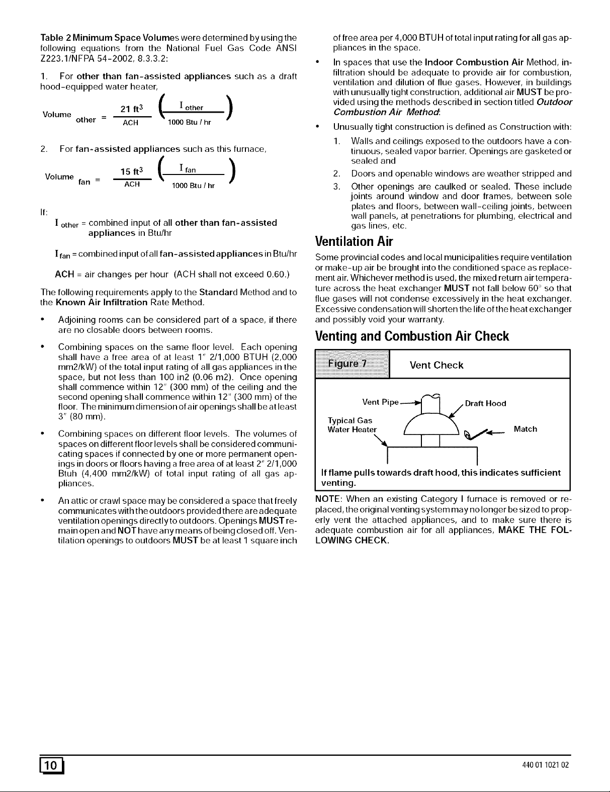
Table 2 Minimum Space Volumes were determined by using the
following equations from the National Fuel Gas Code ANSI
Z223.1/NFPA 54-2002, 8.3.3.2:
1. For other than fan-assisted appliances such as a draft
hood-equipped water heater,
21 if3 ( [ other )
Volume other - ACH 1000 Btu / hr
2. For fan-assisted appliances such as this furnace,
15ft3 ( [fan )
Volume fan = ACH 1000 Btu I hr
If:
[ other = combined input of all other than fan-assisted
appliances in Btu/hr
[ fan = combined input of all fan-assisted appliances in Btu/hr
ACH = air changes per hour (ACH shall not exceed 0.60.)
The following requirements apply to the Standard Method and to
the Known Air Infiltration Rate Method.
• Adjoining rooms can be considered part of a space, if there
are no closable doors between rooms.
Combining spaces on the same floor level. Each opening
shall have a free area of at least 1" 2/1,000 BTUH (2,000
mm2/kW) of the total input rating of all gas appliances in the
space, but not less than 100 in2 (0.06 m2). Once opening
shall commence within 12" (300 mm) of the ceiling and the
second opening shall commence within 12" (300 mm) of the
floor. The minimum dimension of air openings shall be at least
3" (80 mm).
Combining spaces on different floor levels. The volumes of
spaces on different floor levels shall be considered communi-
cating spaces if connected by one or more permanent open-
ings in doors or floors having a free area of at least 2" 2/1,000
Btuh (4,400 mm2/kW) of total input rating of all gas ap-
pliances.
An attic or crawl space may be considered a space that freely
communicates with the outdoors provided there are adequate
ventilation openings directly to outdoors. Openings MUST re-
main open and NOT have any means of being closed off. Ven-
tilation openings to outdoors MUST be at least I square inch
of free area per 4,000 BTU H of total input rating for all gas ap-
pliances in the space.
In spaces that use the Indoor Combustion Air Method, in-
filtration should be adequate to provide air for combustion,
ventilation and dilution of flue gases. However, in buildings
with unusually tight construction, additional air MUST be pro-
vided using the methods described in section titled Outdoor
Combustion Air Method:
• Unusually tight construction is defined as Construction with:
1. Walls and ceilings exposed to the outdoors have a con-
tinuous, sealed vapor barrier. Openings are gasketed or
sealed and
2. Doors and openable windows are weather stripped and
3. Other openings are caulked or sealed. These include
joints around window and door frames, between sole
plates and floors, between wall-ceiling joints, between
wall panels, at penetrations for plumbing, electrical and
gas lines, etc.
Ventilation Air
Some provincial codes and local municipalities require ventilation
or make-up air be brought into the conditioned space as replace-
ment air. Whichever method is used, the mixed return air tempera-
ture across the heat exchanger MUST not fall below 60 ° so that
flue gases will not condense excessively in the heat exchanger.
Excessive condensation will shorten the life of the heat exchanger
and possibly void your warranty.
Venting and Combustion Air Check
Vent Check
Vent Pipe-----_l I 7 Draft Hood
Typical Gas f _'_
Wa.erHea.eL / i i Ma.c.
I I
If flame pulls towards draft hood, this indicates sufficient
venting.
NOTE: When an existing Category I furnace is removed or re-
placed, the original venting system may no longer be sized to prop-
erly vent the attached appliances, and to make sure there is
adequate combustion air for all appliances, MAKE THE FOL-
LOWING CHECK.
[_ 44001 102102

CARBON MONOXIDE POISONING HAZARD
Failure to follow the steps outlined below for each
appliance connected to the venting system being
placed into operation, could result in carbon
monoxide poisoning or death:
The following steps shall be followed for each
appliance connected to the venting system being
placed into operation, while all other appliances
connected to the venting system are not in
operation:
1. Seal any unused openings in the venting system.
2. Inspect the venting system for proper size and horizontal
pitch, as required in the National Fuel Gas Code, ANSI
Z223,1/NFPA 54 or CSA B149, 1, Natural Gas and
Propane Installation Code and these instructions. Deter-
mine that there is no blockage or restriction, leakage,
corrosion and other deficiencies which could cause an
unsafe condition.
3. As far as practical, close all building doors and windows
and all doors between the space in which the appliance(s)
connected to the venting system are located and other
spaces of the building.
4. Close fireplace dampers.
5. Turn on clothes dryers and any appliance not connected
to the venting system. Turn on any exhaust fans, such as
range hoods and bathroom exhausts, so they are
operating at maximum speed. Do not operate a summer
exhaust fan.
6. Followthe lighting instructions. Place the appliance being
inspected into operation. Adjust the thermostat so
appliance is operating continuously.
7. Test for spillage from draft hood equipped appliances at
the draft hood relief opening after 5 minutes of main burner
operation. Use the flame of a match or candle. (Figure 7)
8. If improper venting is observed, during any of the above
tests, the venting system must be corrected in
accordance with the National Fuel Gas Code, ANSI
Z223,1/NFPA 54 and/or CSA B149. 1, Natural Gas and
Propane Installation Code.
9. After it has been determined that each appliance
connected to the venting system properly vents when
tested as outlined above, return doors, windows, exhaust
fans, fireplace dampers and any other gas-fired burning
appliance to their previous conditions of use.
For Two Pipe Installation
This furnace can NOT be common vented or connected to any
type B, BW or Lvent or vent connector, nor to any portion of a facto-
ry-built or masonry chimney. Ifthis furnace is replacing a previous-
ly common-vented furnace, it may be necessary to resize the
existing vent and chimney to prevent oversizing problems for the
other remaining appliance(s). See "Venting and Combustion Air
Check"in this section, This furnace MUST be vented to the out-
side.
4. Vent and
Combustion Air Piping
CARBON MONOXIDE POISONING HAZARD.
Failure to properly vent this furnace could result in
death or personal injury.
Use methods described here to provide combustion
and ventilation air.
Single Pipe (N91VlP1Models)
This furnace is certified as a category [V appliance. This furnace
requires ventilation openings to provide air for proper combustion
and ventilation of flue gases. All duct or openings for supplying
44001102102
combustion and ventilation air must comply with the gas codes or
in absence of local codes, the applicable national codes.
When the installation is complete, see the" Venting and Combus-
tion Air Che¢l_' in this manual.
Direct Vent (N9MP2 Models)
This furnace is certified as a category ]V appliance. This furnace
uses outside air for combustion ONLY, it MUST be taken from the
same atmospheric pressure zone as the vent pipe. See Confined
Space Installation in the Combustion and Ventilation Air in this
manual.
Dual Certified (*9MPD Models)
This furnace is certified as a category ]V appliance. This furnace
can be installed as a direct vent furnace using outside air for corn-
bustionorthefurnacecanuseairfrominsidethestructureforcom-
bustion.TheINLETairpipeisoptional.Ifcombustionaircomes
frominsidethestructure,adequatemakeupairMUSTbeprovided
tocompensateforoxygenburned.SeeConfined Space Installa-
tion in the Combustion and Ventilation Air chapter. If combus-
tion air is drawn from outside the structure, it MUST be taken from
the same atmospheric pressure zone as the vent pipe.
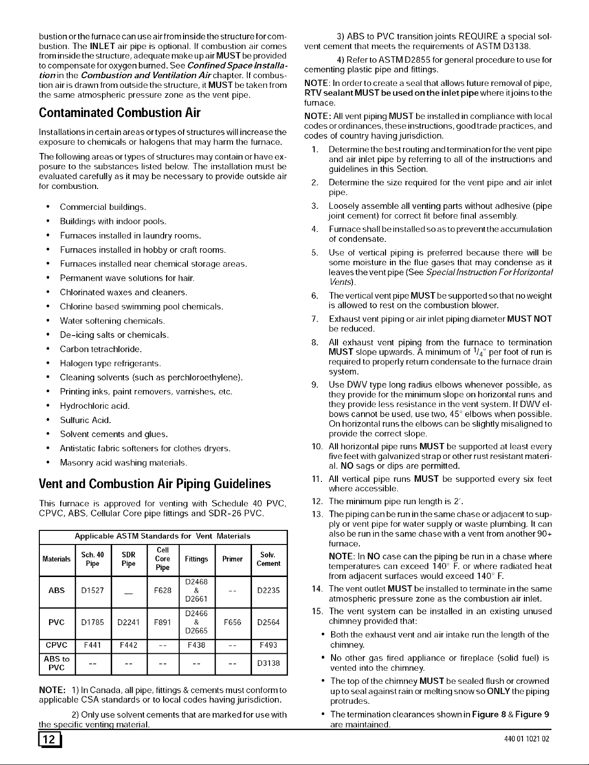
Contaminated Combustion Air
Installations in certain areas or types of structures will increase the
exposure to chemicals or halogens that may harm the furnace.
The following areas or types of structures may contain or have ex-
posure to the substances listed below. The installation must be
evaluated carefully as it may be necessary to provide outside air
for combustion.
• Commercial buildings.
• Buildings with indoor pools.
• Furnaces installed in laundry rooms.
• Furnaces installed in hobby or craft rooms.
• Furnaces installed near chemical storage areas.
• Permanent wave solutions for hair.
• Chlorinated waxes and cleaners.
• Chlorine based swimming pool chemicals.
• Water softening chemicals.
• De-icing salts or chemicals.
• Carbon tetrachloride.
• Halogen type refrigerants.
• Cleaning solvents (such as perchloroethylene).
• Printing inks, paint removers, varnishes, etc.
• Hydrochloric acid.
• Sulfuric Acid.
• Solvent cements and glues.
• Antistatic fabric softeners for clothes dryers.
• Masonry acid washing materials.
Vent and Combustion Air Piping Guidelines
3) ABS to PVC transition joints REQUIRE a special sol-
vent cement that meets the requirements of ASTM D3138.
4) Refer to ASTM D2855 for general procedure to use for
cementing plastic pipe and fittings.
NOTE: In order to create a seal that allows future removal of pipe,
RTV sealant MUST be used on the inlet pipe where itjoins to the
furnace.
NOTE: All vent piping MUST be installed in compliance with local
codes or ordinances, these instructions, good trade practices, and
codes of country having jurisdiction.
1. Determine the best routing and termination for the vent pipe
and air inlet pipe by referring to all of the instructions and
guidelines in this Section.
2. Determine the size required for the vent pipe and air inlet
pipe.
3. Loosely assemble all venting parts without adhesive (pipe
joint cement) for correct fit before final assembly.
4. Furnace shall be installed so as to prevent the accumulation
of condensate.
5. Use of vertical piping is preferred because there will be
some moisture in the flue gases that may condense as it
leaves the vent pipe (See Speciallnstruction ForHorizontal
Vents).
6. The vertical vent pipe MUST be supported so that no weight
is allowed to rest on the combustion blower.
7. Exhaust vent piping or air inlet piping diameter MUST NOT
be reduced.
8. All exhaust vent piping from the furnace to termination
MUST slope upwards. A minimum of 1/4" per foot of run is
required to properly return condensate to the furnace drain
system.
9. Use DWV type long radius elbows whenever possible, as
they provide for the minimum slope on horizontal runs and
they provide less resistance in the vent system. If DWV el-
bows cannot be used, use two, 45 ° elbows when possible.
On horizontal runs the elbows can be slightly misaligned to
provide the correct slope.
10. All horizontal pipe runs MUST be supported at least every
five feet with galvanized strap or other rust resistant materi-
al. NO sags or dips are permitted.
11. All vertical pipe runs MUST be supported every six feet
where accessible.
This furnace is approved for venting with Schedule 40 PVC,
CPVC, ABS, Cellular Core pipe fittings and SDR-26 PVC.
Applicable ASTM Standards for Vent Materials
Cell
Sch.40 SDR Solv.
Core Fittings Primer
Materials Pipe Pipe Pipe Cement
D2468
ABS D1527 F628 & -- D2235
D2661
D2466
PVC D1785 D2241 F891 & F656 D2564
D2665
CPVC F441 F442 -- F438 -- F493
ABS to
.......... D3138
PVC
NOTE: 1) In Canada, all pipe, fittings & cements must conform to
applicable CSA standards or to local codes having jurisdiction.
2) Only use solvent cements that are marked for use with
the specific ventinq, material.
12.
13.
The minimum pipe run length is 2'.
The piping can be run inthe same chase or adjacent to sup-
ply or vent pipe for water supply or waste plumbing. It can
also be run in the same chase with a vent from another 90+
furnace.
NOTE: In NO case can the piping be run in a chase where
temperatures can exceed 140 ° F. or where radiated heat
from adjacent surfaces would exceed 140 ° F.
14. The vent outlet MUST be installed to terminate in the same
atmospheric pressure zone as the combustion air inlet.
15. The vent system can be installed in an existing unused
chimney provided that:
• Both the exhaust vent and air intake run the length of the
chimney.
• No other gas fired appliance or fireplace (solid fuel) is
vented into the chimney.
• The top of the chimney MUST be sealed flush or crowned
up to seal against rain or melting snow so ONLY the piping
protrudes.
• The termination clearances shown in Figure 8 & Figure 9
are maintained.
44001 102102
16.Furnaceapplicationswithverticalventsrequiringventdi-
ameterincreaserfittingsmusthaveincreaserfittings
installedinverticalportionofthe vent. Condensate will be
trapped in the vent if the vent diameter is increased prior to
having an elbow turned upward. This could cause nuisance
tripping of the pressure switch.
Combustion Air and Vent Piping Insulation
Guidelines
NOTE: Use closed cell, neoprene insulation or equivalent. If Fiber-
glass or equivalent insulation is used it must have a vapor barrier.
Use Rvalues of 7 upto 10', R-11 if exposure exceeds 10'. If Fiber-
glass insulation is used, exterior to the structure, the pipe MUST
be boxed in and sealed against moisture.
1. When the vent or combustion air pipe height above the roof
exceeds 30", or if an exterior vertical riser is used on a hori-
zontal vent to get above snow levels, the exterior portion
MUST be insulated.
2. When combustion air inlet piping is installed above a sus-
pended ceiling, the pipe MUST be insulated with moisture
resistant insulation such as Armaflex or other equivalent
type of insulation.
3. Insulate combustion air inlet piping when run in warm, hu-
mid spaces.
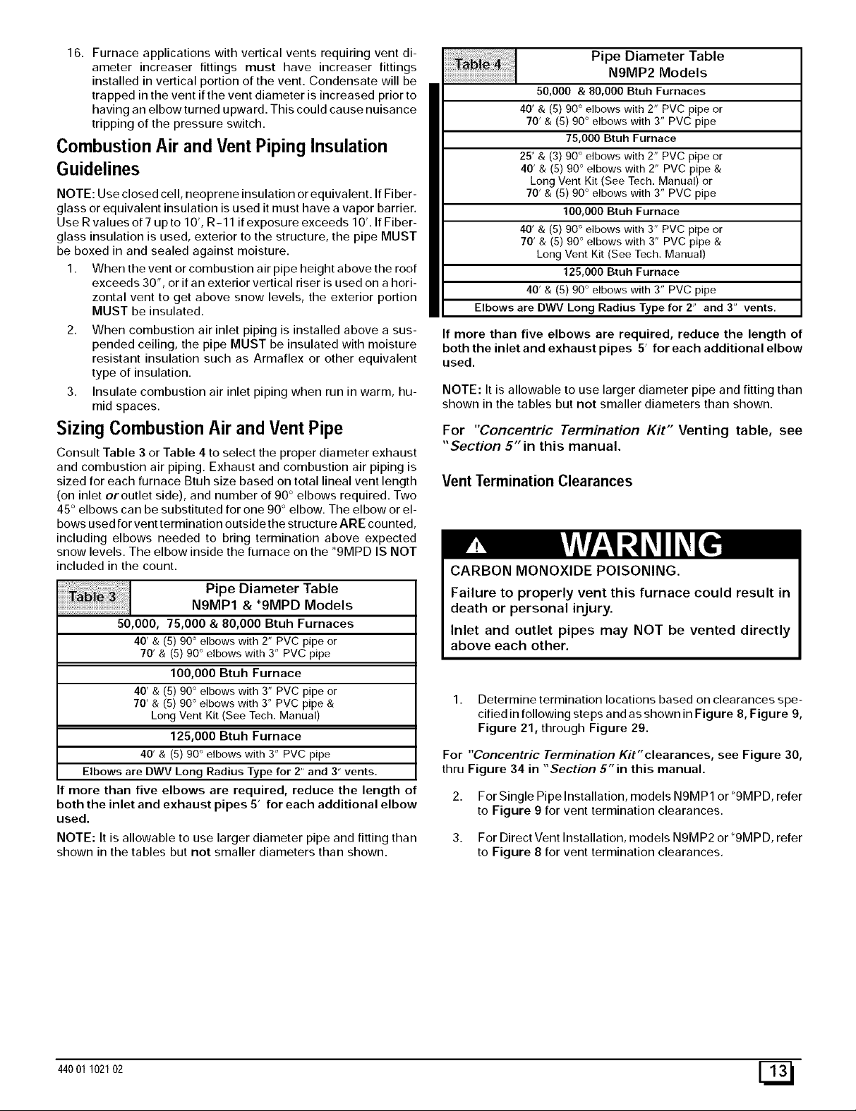
Sizing Combustion Air and Vent Pipe
Consult Table 3 or Table 4 to select the proper diameter exhaust
and combustion air piping. Exhaust and combustion air piping is
sized for each furnace Btuh size based on total lineal vent length
(on inlet oroutlet side), and number of 90 ° elbows required. Two
45 ° elbows can be substituted for one 90 ° elbow. The elbow or el-
bows used for vent termination outside the structure ARE counted,
including elbows needed to bring termination above expected
snow levels. The elbow inside the furnace on the *9MPD IS NOT
included in the count.
Pipe Diameter Table
N9MP1 & *9MPD Models
50,000, 75,000 & 80,000 Btuh Furnaces
40' & (5) 90 ° elbows with 2" PVC pipe or
70' & (5) 90° elbows with 3" PVC pipe
100,000 Btuh Furnace
40' & (5) 90 ° elbows with 3" PVC pipe or
70' & (5) 90° elbows with 3" PVC pipe &
Long Vent Kit (See Tech. Manual)
125,000 Btuh Furnace
40' & (5) 90° elbows with 3" PVC pipe
Elbows are DWV Long Radius Type for 2" and 3" vents.
If more than five elbows are required, reduce the length of
both the inlet and exhaust pipes 5' for each additional elbow
used.
NOTE: It is allowable to use larger diameter pipe and fitting than
shown in the tables but not smaller diameters than shown.
Pipe Diameter Table
N9MP2 Models
50,000 & 80,000 Btuh Furnaces
40' & (5) 90 ° elbows with 2" PVC pipe or
70' & (5) 90° elbows with 3" PVC pipe
75,000 Btuh Furnace
25' & (3) 90 ° elbows with 2" PVC pipe or
40' & (5) 90° elbows with 2" PVC pipe &
Long Vent Kit (See Tech. Manual) or
70' & (5) 90° elbows with 3" PVC pipe
100,000 Btuh Furnace
40' & (5) 90 ° elbows with 3" PVC pipe or
70' & (5) 90° elbows with 3" PVC pipe &
Long Vent Kit (See Tech. Manual)
125,000 Btuh Furnace
40' & (5) 90° elbows with 3" PVC pipe
Elbows are DWV Long Radius Type for 2" and 3" vents,
If more than five elbows are required, reduce the length of
both the inlet and exhaust pipes 5' for each additional elbow
used.
NOTE: It is allowable to use larger diameter pipe and fitting than
shown in the tables but not smaller diameters than shown.
For "Concentric Termination Kit" Venting table, see
"Section 5" in this manual.
Vent Termination Clearances
CARBON MONOXIDE POISONING.
Failure to properly vent this furnace could result in
death or personal injury.
Inlet and outlet pipes may NOT be vented directly
above each other.
1. Determine termination locations based on clearances spe-
cified in following steps and as shown in Figure 8, Figure 9,
Figure 21, through Figure 29.
For "Concentric Termination Kit"clearances, see Figure 30,
thru Figure 34 in "Section 5"in this manual.
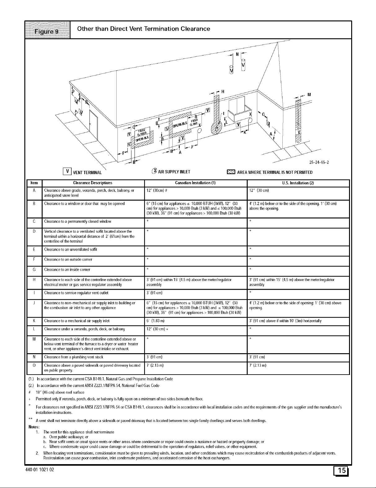
2. For Single Pipe Installation, models N9MP1 or *9MPD, refer
to Figure 9 for vent termination clearances.
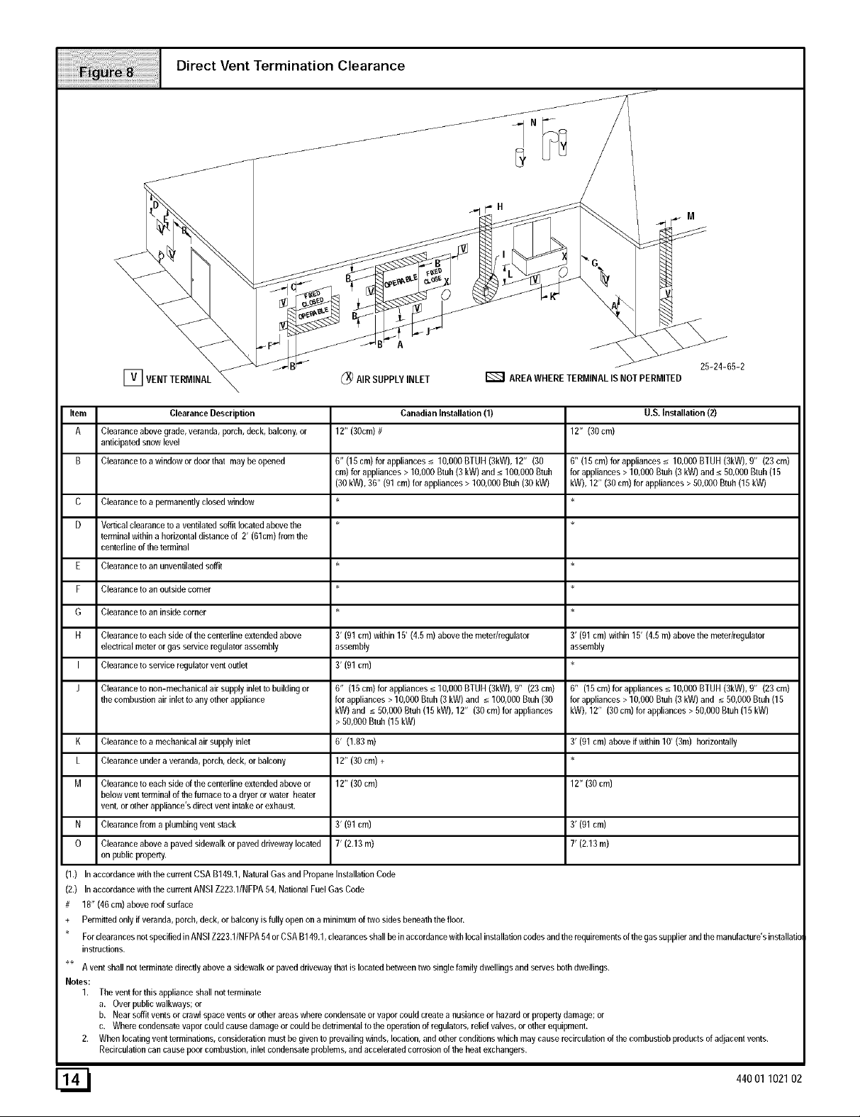
3. For Direct Vent Installation, models N9MP2 or*9MPD, refer
to Figure 8 for vent termination clearances.
44001 102102 E_
ii
[_ AIR SUPPLY INLET D AREA WHERE TERMINAL IS NOT PERMITED
Item Clearance Description
A Clearance above grade, veranda, porch, deck, balcony, or
anticipated snow level
B Clearance to a window or door that may be opened
C
D
E
F
G
H
I
J
Clearance to a permanently closed window
Vertical clearance to a ventilated soffit located above the *
terminal within a horizontal distance of 2' (61cm) from the
centedine of the terminal
Clearance to an unventilated soffit *
Clearance to an outside corner
Clearance to an inside comer
Clearance to each side of the centedine extended above
eleclrical meter or gas service regulator assembly
Clearance to service regulator vent outlet
Clearance to non-mechanical air supply inlet to building or
the combustion air inlet to any other appliance
Canadian Installation (1)
12" (30cm)#
6" (15 cm) for appliances _<10,000 BTUH (3kW), 12" (30
cm) for appliances > 10,000 Btuh (3 kW) and _<100,000 Btuh
(30 kW), 36" (91 cm) for appliances > 100,000 Btub (30 kW)
3' (91 cm) within 15' (4.5 m) above the meter/regulator
assembly
3' (91 cm)
6" (15cm)forappliances_<10,OOOBTUH(3kW),g" (23cm)
forappliances> 10,000Btuh(3kW) and _<100,000Btuh(30
kW) and _<50,000Btuh(15kW), 12" (30 cm)forappliances
> 50,000Btuh(15kW)
K Clearance to a mechanical air supply inlet 6' (1.83 m)
L Clearance under a veranda, porch, deck, or balcony 12" (30 cm) +
M Clearance to each side of the centedine extended above or 12" (30 cm)
below vent terminal of the furnace to a dryer or water heater
vent, or other appliance's direct vent intake or exhaust.
N Clearance from a plumbing vent stack 3' (91 cm)
O Clearance above a paved sidewalk or paved driveway located 7' (2.13 m)
on public property.
(1.) In accordance with the current CSA B149.1, Natural Gas and Propane Installation Code
(2,) In accordance with the current ANSI Z223.1/NFPA 54, National Fuel Gas Cede
# 18" (46 cm) above roof surface
+ Permitted only if veranda, porch, deck, or balcony is fully open on a minimum of two sides benealh the floor.
U.S. Installation (2)
12" (30 cm)
6" (15 cm) for appliances _< 10,000 BTUH (3kW), 0" (23 cm)
for appliances > 10,000 Btuh (3 kW) and _<50,000 Btuh (15
kW), 12" (30 cm) for appliances > 50,000 Btuh (15 kW)
3' (91 cm) within 15' (4.5 m) above the meter/regulator
assembly
6" (15cm)forappliances_<10,OOOBTUH(3kW),9" (23cm)
for appliances>10,000Btuh(3 kW)and _<50,000Btub(15
kW),12" (30 cm)for appliances> 50,000Btuh (15kW)
3' (91 cm) above if within 10' (3m) horizontally
12" (30 cm)
3' (91 cm)
7' (2,13 m)
For dearances not specified in ANSI Z223.1/N FPA 54 or C SA B149,1, clearances shall be in accordance with local installation codes and the requirements of the gas supplier and the manufacture's installatio
instructions.
A vent shall not terminate directly above a sidewalk orpaved driveway that is located between two single family dwellings and serves both dwellings.
Notes:
1, The vent for this appliance shall not terminate
a. Over public walkways; or
b. Near soffit vents or crawl space vents or other areas where condensate or vapor could create anusiance or hazard or property damage; or
c. Where condensate vapor could cause damage or could be detrimental to the operation of regulators, relief valves, or other equipment.
2. When locating vent terminations, consideration must be given to prevailing winds, location, and other conditions which may cause recirculation of the combustiob products of adjacent vents.
Recirculation can cause poor combustion, inlet condensate problems, and accelerated corrosion of the heat exchangers.
[_ 440O1102102
_E "I" 1"I 25-24-65-2
[_ VENT TERMINAL _ AIR SUPPLY INLET _ AREA WHERE TERMINAL IS NOT PERMITED
Item Clearance Descriptions
A Clearance above grade, veranda, porch, deck, balcony, or
anticipated snow level
B Clearance to a window or door that may be opened
Canadian Installation (1)
12" (30cm)#
6" (15 cm) for appliances _<10,000 BTUH (3kW), 12" (30
cm) for appliances > 10,000 Btuh (3 kW) and _<100,000 Btuh
(30 kW), 36" (01 cm) for appliances > 100,000 Btub (30 kW)
C Clearance to a permanently closed window *
D Vertical clearance to a ventilated soffit located above the *
terminal within a horizontal distance of 2' (61cm) from the
centedine of the terminal
E Clearance to an unventilated soffit *
F Clearance to an outside corner *
G Clearance to an inside comer *
H Clearance to each side of the centedine extended above
electrical meter or gas service regulator assembly
I Clearance to service regulator vent outlet
J Clearance to non-mechanical air supply inlet to building or
the combustion air inlet to any other appliance
K Clearance to a mechanical air supply inlet
L Clearance under a veranda, porch, deck, or balcony
M Clearance to each side of the centedine extended above or *
below vent terminal of the furnace to a dryer or water heater
vent, or other appliance's direct vent intake or exhaust.
N Clearance from a plumbing vent stack
O Clearance above a paved sidewalk or paved driveway located
on public property.
3' (01 cm) within 15' (4.5 m) above the meter/regulator
assembly
3' (01 cm)
fi" (15cm)forappliances_<10,OOOBTUH(3kW),12" (30
cm)forappliances> 10,000Btub(3kW) and _<100,000Btuh
(30 kW),36" (91cm)forappliances> 100,000Btuh(30 kW)
6' (1.83m)
12" (30 cm) +
3' (91 cm)
7' (2.13 m)
U.S. Installation (2)
12" (30 cm)
4' (1.2 m) below or to the side of the opening. 1' (30 cm)
above the opening.
3' (91 cm) within 15' (4.fi m) above the meter/regulator
assembly
4' (1.2 m) below or to the side of opening: 1' (30 cm) above
opening.
3' (01 cm) above if within 10' (3m) horizontally
3' (91 cm)
7' (2.13 m)
(1.) In accordance with the current CSA B149.1, Natural Gas and Propane Installation Code
(2.) In accordance with the current ANSI Z223.1/NFPA fi4, Nafional Fuel Gas Code
# 18" (46 cm) above roof surface
+ Permitted only if veranda, porch, deck, or balcony is fully open on a minimum of two sides beneath the floor.
For clearances not specified in ANSI Z223.1/NFPA 54 or CSA B149.1, clearances shall be in accordance with local installation codes and the requirements of the gas supplier and the manufacture's
installation instructions.
A vent shall not terminate directly above a sidewalk orpaved driveway that is located between two single family dwellings and serves both dwellings.
Notes:
1. The vent for this appliance shall not terminate
a. Over punic walkways; or
b. Near soffit vents or crawl space vents or other areas where condensate or vapor could create anusiance or hazard or property damage; or
c. Wherec_ndensateva__rc_u_dcausedamage_rcou_dbedetrimentaIt_the_perafi_n_fregu_at_rs_re_iefvaIves__r_there_ui_ment_
2. When locating vent terminations, consideration must be given to prevailing winds, location, and other conditions which may cause recirculation of the combusfiob products of adjacent vents.
Recirculafion can cause poor combustion, inlet condensate problems, and accelerated corrosion of the heat exchangers.
44001 102102 E_I
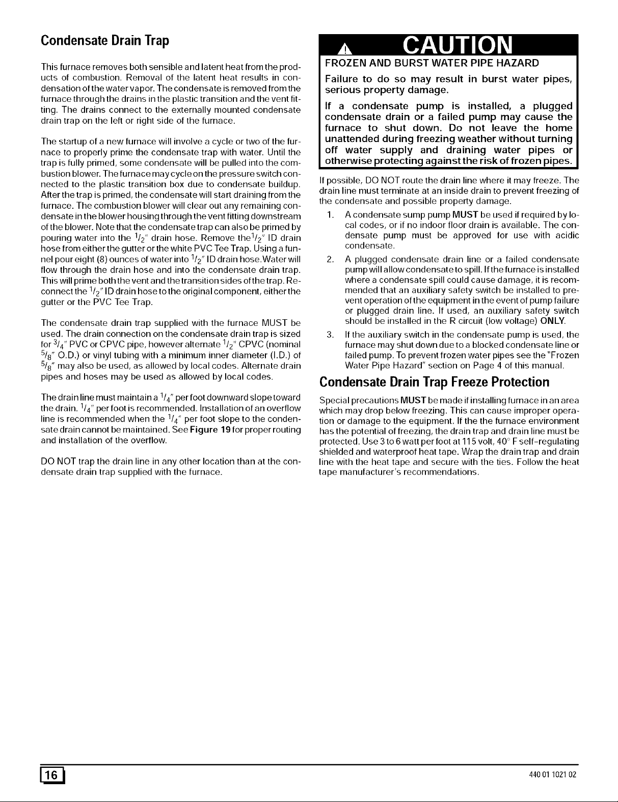
CondensateDrainTrap
This furnace removes both sensible and latent heat from the prod-
ucts of combustion. Removal of the latent heat results in con-
densation of the water vapor. The condensate is removed from the
furnace through the drains in the plastic transition and the vent fit-
ting. The drains connect to the externally mounted condensate
drain trap on the left or right side of the furnace.
The startup of a new furnace will involve a cycle or two of the fur-
nace to properly prime the condensate trap with water. Until the
trap is fully primed, some condensate will be pulled into the com-
bustion blower. The furnace may cycle on the pressure switch con-
nected to the plastic transition box due to condensate buildup.
After the trap is primed, the condensate will start draining from the
furnace. The combustion blower will clear out any remaining con-
densate in the blower housing through the vent fitting downstream
of the blower. Note that the condensate trap can also be primed by
pouring water into the 1/2" drain hose. Remove the1/2 " ID drain
hose from either the gutter or the white PVC Tee Trap. Using a fun-
nel pour eight (8) ounces of water into 1/2" ID drain hose.Water will
flow through the drain hose and into the condensate drain trap.
This will prime both the vent and the transition sides of the trap. Re-
connect the 1/2, ID drain hose to the original component, either the
gutter or the PVC Tee Trap.
The condensate drain trap supplied with the furnace MUST be
used. The drain connection on the condensate drain trap is sized
for 3/4" PVC or CPVC pipe, however alternate 1/2" CPVC (nominal
5/8" O.D.) or vinyl tubing with a minimum inner diameter (I.D.) of
5/8" may also be used, as allowed by local codes. Alternate drain
pipes and hoses may be used as allowed by local codes.
The drain line must maintain a 1/4" per foot downward slope toward
the drain. 1/4" per foot is recommended. Installation of an overflow
line is recommended when the 1/4" per foot slope to the conden-
sate drain cannot be maintained. See Figure 19 for proper routing
and installation of the overflow.
DO NOT trap the drain line in any other location than at the con-
densate drain trap supplied with the furnace.
FROZEN AND BURST WATER PIPE HAZARD
Failure to do so may result in burst water pipes,
serious property damage.
If a condensate pump is installed, a plugged
condensate drain or a failed pump may cause the
furnace to shut down. Do not leave the home
unattended during freezing weather without turning
off water supply and draining water pipes or
otherwise protecting against the risk of frozen pipes.
If possible, DO NOT route the drain line where it may freeze. The
drain line must terminate at an inside drain to prevent freezing of
the condensate and possible property damage.
1. A condensate sump pump MUST be used if required by lo-
cal codes, or if no indoor floor drain is available. The con-
densate pump must be approved for use with acidic
condensate.
2. A plugged condensate drain line or a failed condensate
pump will allow condensate to spill. If the furnace is installed
where a condensate spill could cause damage, it is recom-
mended that an auxiliary safety switch be installed to pre-
vent operation of the equipment in the event of pump failure
or plugged drain line. If used, an auxiliary safety switch
should be installed in the R circuit (low voltage) ONLY.
3. If the auxiliary switch in the condensate pump is used, the
furnace may shut down dueto a blocked condensate line or
failed pump. To prevent frozen water pipes see the "Frozen
Water Pipe Hazard" section on Page 4 of this manual.
Condensate Drain Trap Freeze Protection
Special precautions MUST be made if installing furnace in an area
which may drop below freezing. This can cause improper opera-
tion or damage to the equipment. If the the furnace environment
has the potential of freezing, the drain trap and drain line must be
protected. Use 3 to 6 watt per foot at 115 volt, 40 ° Fself-regulating
shielded and waterproof heat tape. Wrap the drain trap and drain
line with the heat tape and secure with the ties. Follow the heat
tape manufacturer's recommendations.
[_ 44001 102102
............................=;;;;;;;;;;;;;===== ; ==========_i_!ii ii !1 Upflow Installations Top vent
On Some Models
ONLY
Single Pressure Switch
VentDrain
& Clamps
(Optional)
Dual Pressure Switch Detail
Drain Tube
Black Rubber
l/z" ID & Clamps
Drain Tube
Corrugate(
& Clamps
Drain Connector Black PVC
3/4" PVC X 1/2" CPVC
(Loose parts bag)
Casing Grommet
S/8"ID
(Looseparts bag)
Relief Tube
Black Rubber
3/16" ID
Street Elbow
1/2" CPVC
(Loose parts bag)
Drain Line Vent Tee 3/4" PVC or
1/2" CPVC (Field supplied)
DrainTube BlackRubber /8 ID& Clamps,
Cut lengthto fit(Loosepartsbag)
25-24-80
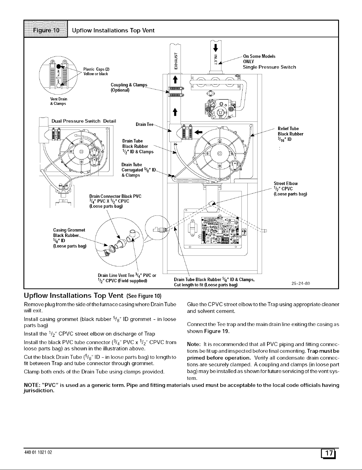
Upflow Installations Top Vent (SeeFigure10)
Remove plug from the side of the furnace casing where Drain Tu be
will exit.
Install casing grommet (black rubber 5/8" ID grommet - in loose
parts bag)
Install the 1/2" CPVC street elbow on discharge of Trap
Install the black PVC tube connector (3/4" PVC x 1/2" CPVC from
loose parts bag) as shown in the illustration above.
Cut the black Drain Tube (5/8" ID - in loose parts bag) to length to
fit between Trap and tube connector through grommet.
Clamp both ends of the Drain Tube using clamps provided.
Glue the CPVC street elbow to the Trap using appropriate cleaner
and solvent cement.
Connect the Tee trap and the main drain line exiting the casing as
shown Figure 19.
Note: It is recommended that all PVC piping and fitting connec-
tions be fit up and inspected before final cementing. Trap must be
primed before operation. Verify all condensate drain connec-
tions are securely clamped. A coupling and clamps (in loose part
bag) may be installed as shown for future servicing of the vent sys-
tem.
NOTE: "PVC" is used as a generic term. Pipe and fitting materials used must be acceptable to the local code officials having
jurisdiction.
44001 102102 E_

UpflowInstallationsVentthruLeftSide
Plastic Cap
Yellow or black
Coupling & Clamps
VentDrain Either: ThePVC
&Clamps Drain Teeor afield
supplied2" PVC Tee
Dual Pressure Switch Detail
Tee Trap White PVC
(loose parts bag)
Drain Tube
Black Rubber
1/2" ID & Clam
DrainConnector Black PVC
3/4"PVCX 1/2"CPVC
(Looseparts bag)
Drain Tube
Corrugated
s/8" ID & Clamps
Casing Grommet
Black Rubber
s/8"ID
(Loose parts bag)
2" PVCCoupling
On SomeModels
ONLY
S_lt_llchPressure
o o
3/16"IDRubberTube
/-
SIDE VIEW
/_ Rotatedownward
/_5° to10°
NOT
be angled5°to 10° also.
DrainLineVentTee3/4"PVCor 1/2"CPVC(Fieldsupplied)
Upflow Installations Vent thru Left Side (SeeFigure11)
Remove Drain Tee from inducer discharge and remove black
Drain Tube (1/2" ID) from bottom of Drain Tee. (*9MPD models
only)
Install Vent Pipe grommet in side of casing.
Cut an appropriate length of 2" PVC pipe long enough to exit the
cabinet and connect the vent drain to either:
• A standard field supplied 2" PVC tee (N9MP1 models), or
• A 2" PVC coupling fastened onto the Drain Tee (*9MPD mod-
els)
Install Tee trap into bottom of tee.
Install the 112" CPVC street elbow on discharge of Trap
Install the black PVC drain connector (3/4" PVC x 1/2" CPVC from
loose parts bag) as shown in the illustration above.
25-24-81
Cut the black Drain Tube (5/8" ID - in loose parts bag) to length to
fit between Trap and tube connector through grommet.
Clamp both ends of the Drain Tube using clamps provided.
Glue the CPVC street elbow to the Trap using appropriate cleaner
and solvent cement.
Connect the Tee trap and the main drain line exiting the casing as
shown in Figure 19.
Note: It is recommended that all PVC piping and fitting connec-
tions be fit up and inspected before final cementing. Both the in-
ternal Trap and the external Tee Trap must be primed before
operation. Verify all condensate drain connections are securely
clamped. A coupling and clamps (in loose part bag) may be
installed as shown for future servicing of the vent system.
[_ 44001 102102
Plastic Cap
Yellow or black
/
VentDrain
&Clamps
DrainTube
Corrugated
sis"
SIDE VIEW
_otate downward
NOTE.TBuilt-inchannelwill
beangled 5° to10° also.
All Models Vent thru Right Side
_On Some Models
ONLY
ReliefTube
BlackRubber
"ID
"BarbedCoupling, 1/2" OD
Either:ThePVC
DrainTeeor afield
"_ingle Pressure Switch Detail
DrainLine VentTee3/4"PVC
CPVC(Field supplied)
DrainConnector Black PVC
3/4"PVC X llz" CPVC
(Looseparts bag)
Grommet
"BlackRubberS_" CPVC
(Looseparts bag)
25-24-82
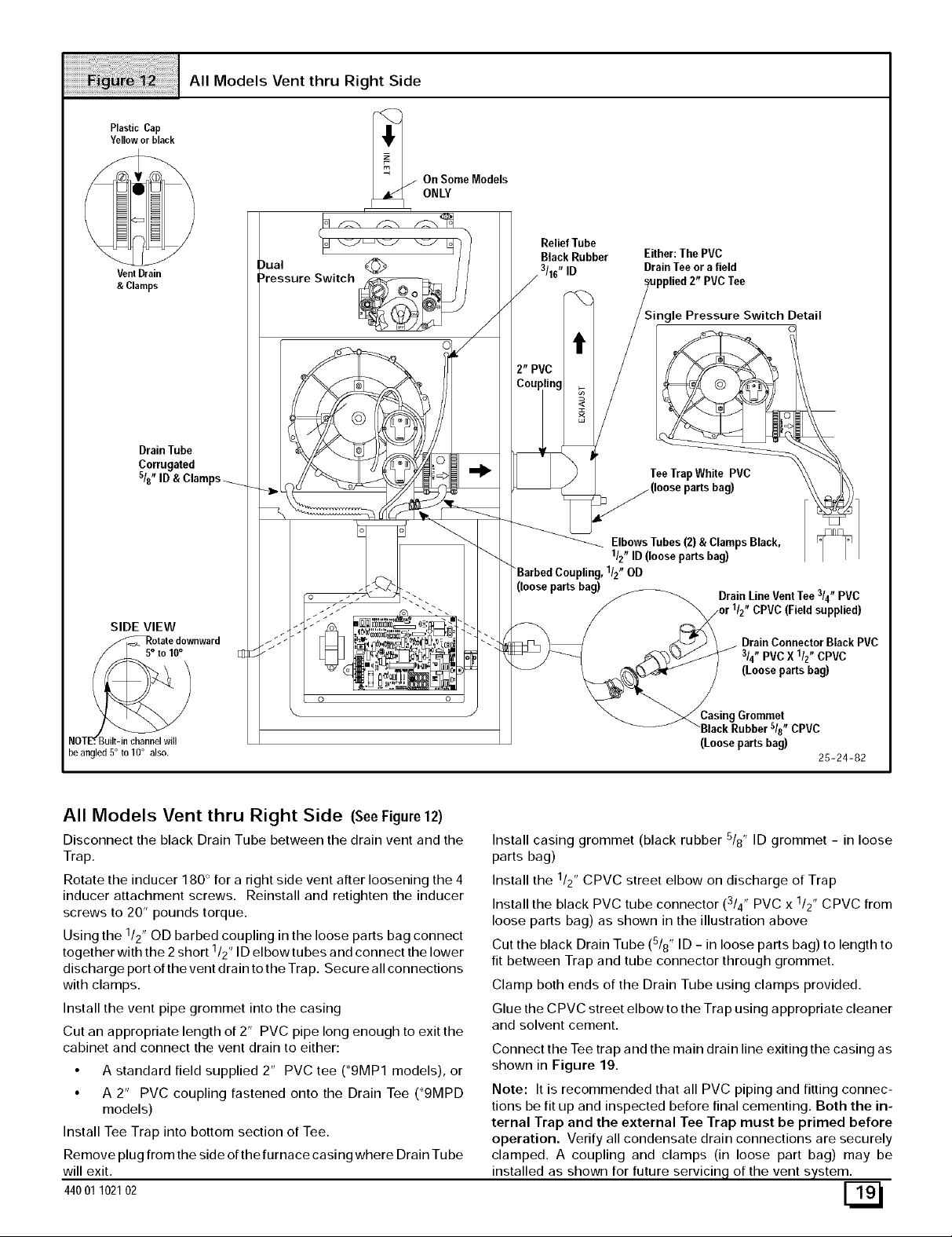
All Models Vent thru Right Side (SeeFigure 12)
Disconnect the black Drain Tube between the drain vent and the
Trap.
Rotate the inducer 180 ° for a right side vent after loosening the 4
inducer attachment screws. Reinstall and retighten the inducer
screws to 20" pounds torque.
Using the 1/2" OD barbed coupling in the loose parts bag connect
1 ,
together with the 2 short /2' ID elbowtubes and connect the lower
discharge port of the vent drain to the Trap. Secure all connections
with clamps.
Install the vent pipe grommet into the casing
Cut an appropriate length of 2" PVC pipe long enough to exit the
cabinet and connect the vent drain to either:
• A standard field supplied 2" PVC tee (_9MP1 models), or
• A 2" PVC coupling fastened onto the Drain Tee (_9MPD
models)
Install Tee Trap into bottom section of Tee.
Remove plug from the side of the furnace casing where Drain Tube
will exit.
44001 102102
Install casing grommet (black rubber 5/8" ID grommet - in loose
parts bag)
Install the 1/2" CPVC street elbow on discharge of Trap
3 ,
Install the black PVC tube connector ( /4' PVC x 1/2" CPVC from
loose parts bag) as shown in the illustration above
Cut the black Drain Tube (5/8" ID - in loose parts bag) to length to
fit between Trap and tube connector through grommet.
Clamp both ends of the Drain Tube using clamps provided.
Glue the CPVC street elbow to the Trap using appropriate cleaner
and solvent cement.
Connect the Tee trap and the main drain line exiting the casing as
shown in Figure 19.
Note: It is recommended that all PVC piping and fitting connec-
tions be fit up and inspected before final cementing. Both the in-
ternal Trap and the external Tee Trap must be primed before
operation. Verify all condensate drain connections are securely
clamped. A coupling and clamps (in loose part bag) may be
installed as shown for future servicing of the vent system.
 Loading...