


C9MPT050F12B1
ICP C9MPT050F12B1, C9MPT075F14B1, C9MPT100J16B1, C9MPT125L20B1, C9MPV050F12B1 Installation Guide
...
90+2-stage& *9MPT & *9MPV
VariableSpeed
Category ry
!veoFU!onroaCeo,. CT
S ct IV definition.
FAN ASSISTED,
SAFETY REQUIREMENTS
This furnace ca nbe installed as adirect vent furnace using outside air for combustion or the furnace can use air from inside the structure for combustion.
The INLET air pipe is optional. If combustion air comes from inside the structure, adequate make up air MUST be provided to compensate for oxygen
burned. See the Indoor Combustion Airsection inthe Combustion and Ventilation Aircha pter. If combustion air is drawn from outside the structure, it
MUST be taken from the same atmospheric pressure zone as the vent pipe.
Recognize safety information. This is the safety- alert symbolS. I .When you see this symbol on the furnace and in instructions manuals be alert to the
potential for personal injury.
Understand the signal words DANGER, WARNING, or CAUTION. These words are used with the safety-alert symbol. DANGER identifies the most
serious hazards, those that will result in severe personal injury or death. WARNING signifies a hazard that could result in personal injury or death.
CAUTION is used to identify unsafe practices that may result in minor personal injury or product and property damage. NOTE is used to highlight
suggestions that will result in enhanced installation, reliability, or operation.
Installing and servicing heating equipment can be hazardous due to gas and electrical components. Only trained and qualified personnel should install,
repair, or service heating equipment.
Untrained service personnel can perform basic maintenance functions such as cleaning and replacing air filters. All other operations must be performed
by trained service personnel. When working on heating equipment, observe precautions in the literature, on tags, and on labels attached to or shipped
with the unit and other safety precautions that may apply.
Follow all safety codes. In the United States, follow all safety codes including the current edition National Fuel Gas Code (NFGC) ANSI
Z223.1 - 2002/N FPA No. 54-2002. InCanada, refer tothecurrent edition of the National Standard of Canada Natural Gas and Propane Installation Code
(NSCNGPIC) CSA B149.1-00. Wear safetyglassesandworkgloves. Havefireextinguisher availableduringstart-upand adjustment procedures and
service calls.
These instructions cover minimum requirements and conform to existing national standards and safety codes. In some instances, these instructions
exceed certain local codes and ordinances, especially those that may not have kept up with changing residential construction practices. We require
these instructions as a minimum for a safe installation.
,j'_' %%
! i¸¸
International Comfort Products, LLC
Lewisburg, TN 37091
Table of Contents
1.SafeInstallation Requirements ................... 3
2.Installation ................................... 4
3.Combustion&VentilationAir ..................... 8
4.Vent& CombustionAir Piping ................... 12
5.GasSupply and Piping ........................ 30
6.ElectricalWiring .............................. 33
ELECTRIC SHOCK HAZARD
Failure to follow safety
warnings exactly could result
in serious injury, death, and/or
property damage.
Turn Off All Power Before
Servicing.
Printed in U.S.A. 2/9/2005 440 01 2020 (07)
7. DuctworkandFilter ....................... 35
8. Checks and Adjustments .................... 38
9. FurnaceMaintenance ...................... 40
10.SequenceofOperation & Diagnostics .......... 41
11.Concentric VentTermination................. 46
TechSupportand Parts ....................... 49
CARBON MONOXIDE POISONING AND FIRE
HAZARD.
Failure to follow safety warnings exactly cou Id
result in serious injury, death, and/or property
damage.
This furnace is not designed for use in mobile
homes, trailers or recreational vehicles.
INSTALLER: Affix these instructions
on or adjacent to the furnace.
CONSUMER: Retain these
instructions for future reference.
Dealer Name:
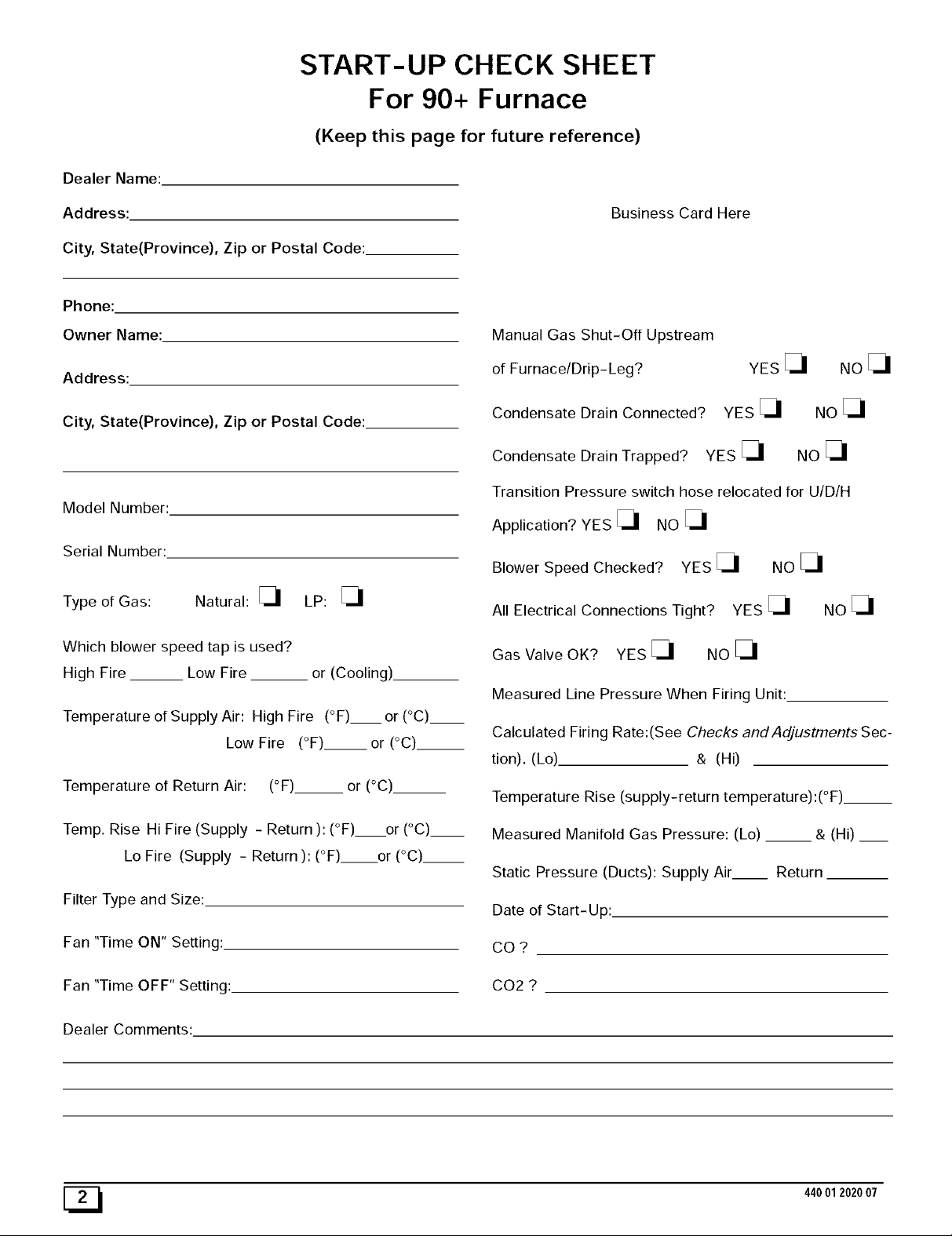
START-UP CHECK SHEET
For 90+ Furnace
(Keep this page for future reference)
Address:
City, State(Province), Zip or Postal Code:
Phone:
Owner Name:
Address:
City, State(Province), Zip or Postal Code:
Model Number:
Serial Number:
Type of Gas: Natural: _ LP:
Which blower speed tap is used?
High Fire __ Low Fire or (Cooling).
Temperature of Supply Air: High Fire (°F)__ or (°C)__
Low Fire (°F).__or (°C)__
Business Card Here
Manual Gas Shut-Off Upstream
of Furnace/Drip- Leg?
Condensate Drain Connected?
Condensate Drain Trapped? YES
Transition Pressure switch hose relocated for U/D/H
Application? YES _ NO
Blower Speed Checked? YES _ NO
All Electrical Connections Tight? YES _ NO
Gas Valve OK? YES _ NO
Measured Line Pressure When Firing Unit:
Calculated Firing Rate:(See Checks and Adjustments Sec-
tion). (Lo) & (Hi)
YES
YES
NOE_
NO
NO
Temperature of Return Air: (°F)__ or (°C)__
Temp. Rise Hi Fire (Supply - Return ): (°F) or (°C)__
Lo Fire (Supply - Return ): (°F) or (°C)__
Filter Type and Size:
Fan "Time ON" Setting:.
Fan "Time OFF" Setting:
Dealer Comments:
[_ 44001202007
Temperature Rise (supply-return temperature):(°F)__
Measured Manifold Gas Pressure: (Lo) __ & (Hi) __
Static Pressure (Ducts): Supply Air Return
Date of Start-Up:
CO?
CO2 ?
1. Safe Installation Requirements
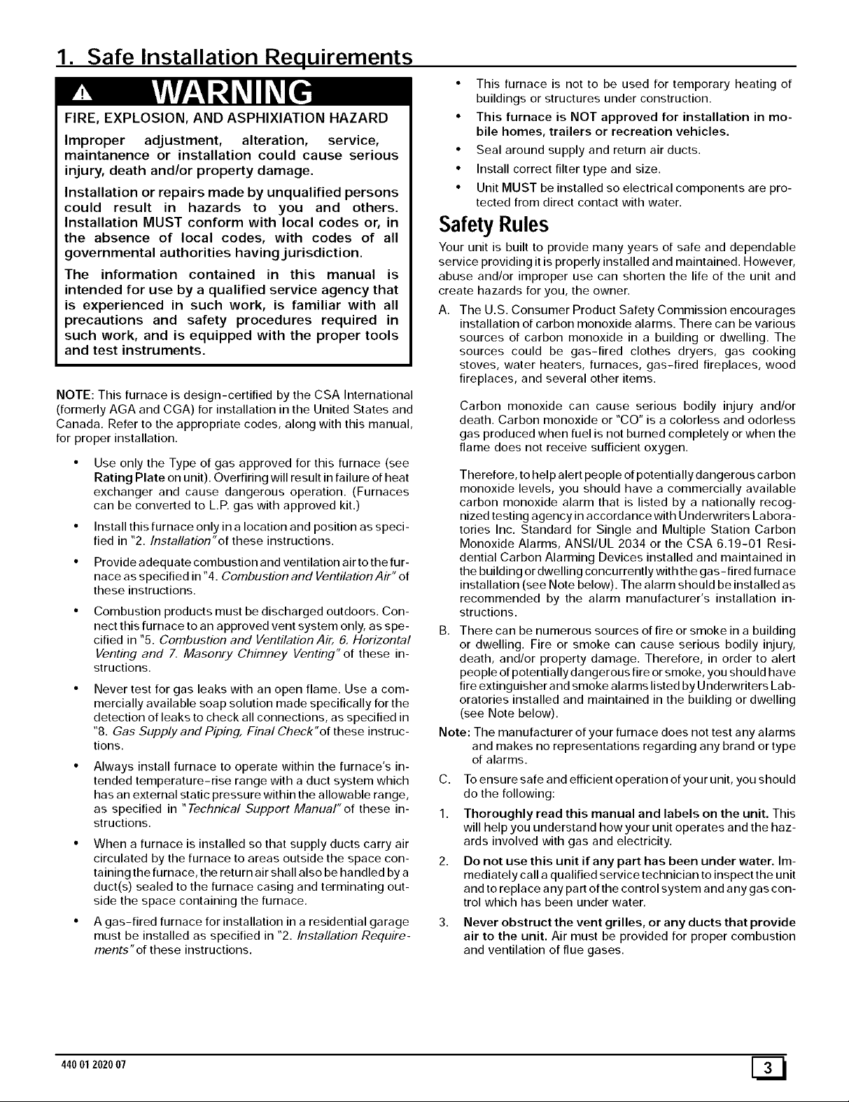
FIRE, EXPLOSION, AND ASPHIXlATION HAZARD
Improper adjustment, alteration, service,
maintanence or installation could cause serious
injury, death and/or property damage.
Installation or repairs made by unqualified persons
could result in hazards to you and others.
Installation MUST conform with local codes or, in
the absence of local codes, with codes of all
governmental authorities having.jurisdiction.
The information contained in this manual is
intended for use by a qualified service agency that
is experienced in such work, is familiar with all
precautions and safety procedures required in
such work, and is equipped with the proper tools
and test instruments.
NOTE: This furnace is design-certified by the CSA International
(formerly AGA and CGA) for installation in the United States and
Canada. Refer to the appropriate codes, along with this manual,
for proper installation.
Use only the Type of gas approved for this furnace (see
Rating Plate on unit). Overfiring will result in failure of heat
exchanger and cause dangerous operation. (Furnaces
can be converted to L.R gas with approved kit.)
Install this furnace only in a location and position as speci-
fied in "2. Installation"of these instructions.
Provide adequate combustion and ventilation air to the fur-
nace as specified in "4. Combustion and Ventilation Air" of
these instructions.
Combustion products must be discharged outdoors. Con-
nect this furnace to an approved vent system only, as spe-
cified in %. Combustion and Ventilation Air, 6. Horizontal
Venting and 7, Masonry Chimney Venting"of these in-
structions.
Never test for gas leaks with an open flame. Use a com-
mercially available soap solution made specifically for the
detection of leaks to check all connections, as specified in
"8. Gas Supply and Piping, Final Check"of these instruc-
tions.
Always install furnace to operate within the furnace's in-
tended temperature-rise range with a duct system which
has an external static pressure within the allowable range,
as specified in "Technical Support Manual" of these in-
structions.
• When a furnace is installed so that supply ducts carry air
circulated by the furnace to areas outside the space con-
taining the furnace, the return air shall also be handled by a
duct(s) sealed to the furnace casing and terminating out-
side the space containing the furnace.
• A gas-fired furnace for installation in a residential garage
must be installed as specified in "2. Installation Require-
ments"of these instructions.
• This furnace is not to be used for temporary heating of
buildings or structures under construction.
• This furnace is NOT approved for installation in mo-
bile homes, trailers or recreation vehicles.
• Seal around supply and return air ducts.
• Install correct filter type and size.
• Unit MUST be installed so electrical components are pro-
tected from direct contact with water.
Safety Rules
Your unit is built to provide many years of safe and dependable
service providing it is properly installed and maintained. However,
abuse and/or improper use can shorten the life of the unit and
create hazards for you, the owner.
A. The U.S. Consumer Product Safety Commission encourages
installation of carbon monoxide alarms. There can be various
sources of carbon monoxide in a building or dwelling. The
sources could be gas-fired clothes dryers, gas cooking
stoves, water heaters, furnaces, gas-fired fireplaces, wood
fireplaces, and several other items.
Carbon monoxide can cause serious bodily injury and/or
death. Carbon monoxide or "CO" is a colorless and odorless
gas produced when fuel is not burned completely or when the
flame does not receive sufficient oxygen.
Therefore, to help alert people of potentially dangerous ca rbon
monoxide levels, you should have a commercially available
carbon monoxide alarm that is listed by a nationally recog-
nized testing agency in accordance with Underwriters Labora-
tories Inc. Standard for Single and Multiple Station Carbon
Monoxide Alarms, ANSI/UL 2034 or the CSA 6.19-01 Resi-
dential Carbon Alarming Devices installed and maintained in
the building or dwelling concurrently with the gas- fired furnace
installation (see Note below). The alarm should be installed as
recommended by the alarm manufacturer's installation in-
structions.
B. There can be numerous sources of fire or smoke in a building
or dwelling. Fire or smoke can cause serious bodily injury,
death, and/or property damage. Therefore, in order to alert
people of potentially dangerous fire or smoke, you should have
fire extinguisher and smoke alarms listed by Underwriters Lab-
oratories installed and maintained in the building or dwelling
(see Note below).
Note: The manufacturer of your furnace does not test any alarms
and makes no representations regarding any brand or type
of alarms.
C. To ensure safe and efficient operation of your unit, you should
do the following:
1. Thoroughly read this manual and labels on the unit. This
will help you understand howyour unit operates and the haz-
ards involved with gas and electricity.
2. Do not use this unit if any part has been under water. Im-
mediately call a qualified service technician to inspect the unit
and to replace any part of the control system and any gas con-
trol which has been under water.
Never obstruct the vent grilles, or any ducts that provide
air to the unit. Air must be provided for proper combustion
and ventilation of flue gases.
44001202007
FrozenWater PipeHazard
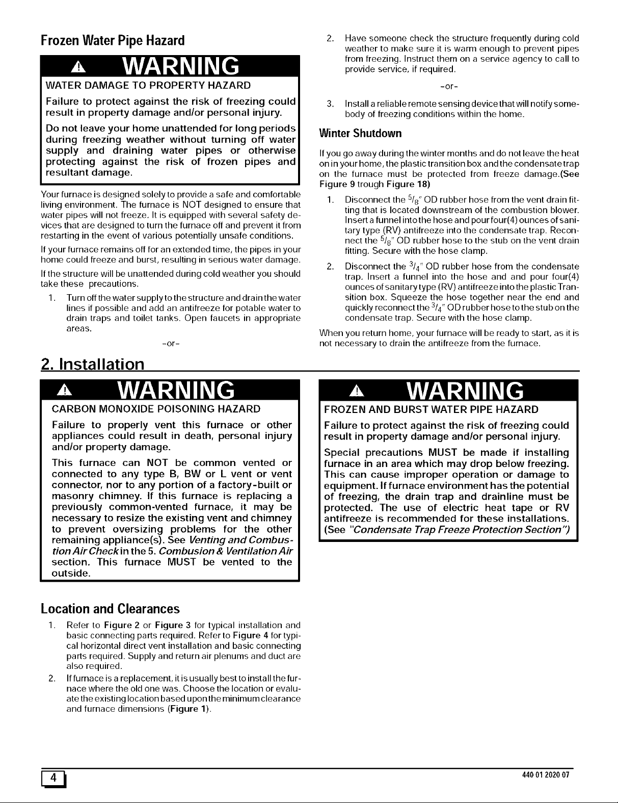
WATER DAMAGE TO PROPERTY HAZARD
Failure to protect against the risk of freezing could
result in property damage and/or personal injury.
Do not leave your home unattended for long periods
during freezing weather without turning off water
supply and draining water pipes or otherwise
protecting against the risk of frozen pipes and
resultant damage.
Your furnace is designed solely to provide a safe and comfortable
living environment. The furnace is NOT designed to ensure that
water pipes will not freeze. It is equipped with several safety de-
vices that are designed to turn the furnace off and prevent it from
restarting in the event of various potentially unsafe conditions.
If your furnace remains off for an extended time, the pipes in your
home could freeze and burst, resulting in serious water damage.
If the structure will be unattended during cold weather you should
take these precautions.
1. Turn off the water supply to the structure and drain the water
lines if possible and add an antifreeze for potable water to
drain traps and toilet tanks. Open faucets in appropriate
areas.
-or-
Have someone check the structure frequently during cold
weather to make sure it is warm enough to prevent pipes
from freezing. Instruct them on a service agency to call to
provide service, if required.
-or-
3. Install a reliable remote sensing device that will notify some-
body of freezing conditions within the home.
Winter Shutdown
If you go away during the winter months and do not leave the heat
on in your home, the plastic transition box and the condensate trap
on the furnace must be protected from freeze damage.(See
Figure 9 trough Figure 18)
1. Disconnect the 5/8" OD rubber hose from the vent drain fit-
ting that is located downstream of the combustion blower.
Insert a funnel into the hose and pour four(4) ounces of sani-
tary type (RV) antifreeze into the condensate trap. Recon-
nect the 5/8" OD rubber hose to the stub on the vent drain
fitting. Secure with the hose clamp.
2. Disconnect the 3/4" OD rubber hose from the condensate
trap. Insert a funnel into the hose and and pour four(4)
ounces of sanitary type (RV) antifreeze into the plastic Tran-
sition box. Squeeze the hose together near the end and
quickly reconnect the 3/4" OD rubber hose to the stub on the
condensate trap. Secure with the hose clamp.
When you return home, your furnace will be ready to start, as it is
not necessary to drain the antifreeze from the furnace.
2. Installation
CARBON MONOXIDE POISONING HAZARD
Failure to properly vent this furnace or other
appliances could result in death, personal injury
and/or property damage.
This furnace can NOT be common vented or
connected to any type B, BW or L vent or vent
connector, nor to any portion of a factory-built or
masonry chimney. If this furnace is replacing a
previously common-vented furnace, it may be
necessary to resize the existing vent and chimney
to prevent oversizing problems for the other
remaining appliance(s). See Venting and Combus-
tion Air Check in the 5. Combusion & Ventilation Air
section. This furnace MUST be vented to the
outside.
Location and Clearances
1. Refer to Figure 2 or Figure 3 for typical installation and
basic connecting parts required. Refer to Figure 4 for typi-
cal horizontal direct vent installation and basic connecting
parts required. Supply and return air plenums and duct are
also required.
2. If furnace is a replacement, it is usually best to install the fur-
nace where the old one was. Choose the location or evalu-
ate the existing location based upon the minimum clearance
and furnace dimensions (Figure 1).
FROZEN AND BURST WATER PIPE HAZARD
Failure to protect against the risk of freezing could
result in property damage and/or personal injury.
Special precautions MUST be made if installing
furnace in an area which may drop below freezing.
This can cause improper operation or damage to
equipment. If furnace environment has the potential
of freezing, the drain trap and drainline must be
protected. The use of electric heat tape or RV
antifreeze is recommended for these installations.
(See "Condensate Trap Freeze Protection Section")
[_ 44001 2020 07
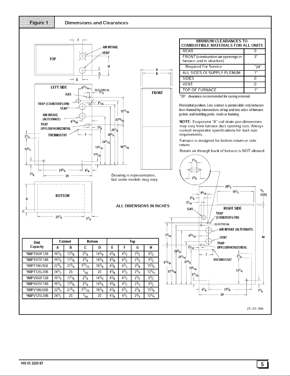
Dimensions and Clearances
TOP
LEFTSIDE F_611/1_
TRAI,_IIIIIrFvLEO_ - " I --
(ALTERNATE)13J_
;RA_OW/HORIZONTAi_
i
THermostAt/_7
i
31/4
i
21518 J 4718
1718
BOTTOM
23118 J 37/8
_I F
_e
GAS
24
COMBUSTIBLE MATERIALS FOR ALL UNITS
MINIMUM CLEARANCES TO
AIRINTAKE
REAR O
FRONT (combustion air openings in 3"
VENi
A
furnace and in structure)
Required For Service *24"
ALL SIDES Of SUPPLY PLENUM 1"
SIDES O
7
ELE TR CAL
_1_/4
/
_11/16
-B-1
FRONT
VENT O
TOP OF FURNACE 1"
"30" clearancerecommendedfor casingremoval.
Horizontalposition:Linecontactispermissibleonlybetween
linesformed by intersectionsoftopand twosidesoffurnace
jacket,andbuildingjoists,studs orframing.
NOTE: Evaporator "A" coil drain pan dimensions
may vary from furnace duct opening size. Always
consult evaporator specifications for duct size
requirements.
2 1/
Furnace is designed for bottom return or side
return.
Return air through back of furnace is NOT allowed.
Drawing is representative,
but some models may vary
2811z --
3/
T' E
23/8--
ALL DIMENSIONS IN INCHES
11116
GAS\
i / 18112
/(COUNTERFLOW)
( _ ELECTRICAL
/AIR INTAKE(ALTERNATE)
f._..IVENT
ZW__ ;_OWIHOR,ZONTAL
-- 7_THH_ERMOSTAT2_
13114
Unit
Capacity
*gMPT050F12B
*gMPT075F14B
*gMPT100J16B
*9MPT125L20B
13116 413116
}7/8 11116_
*9MPV050F12B
*9MPV075F14B
13 11_1/16
*9MPVIOOJ20B
*9MPV125L20B
25-23-36b
44001 2020 07 [_
T
17t8
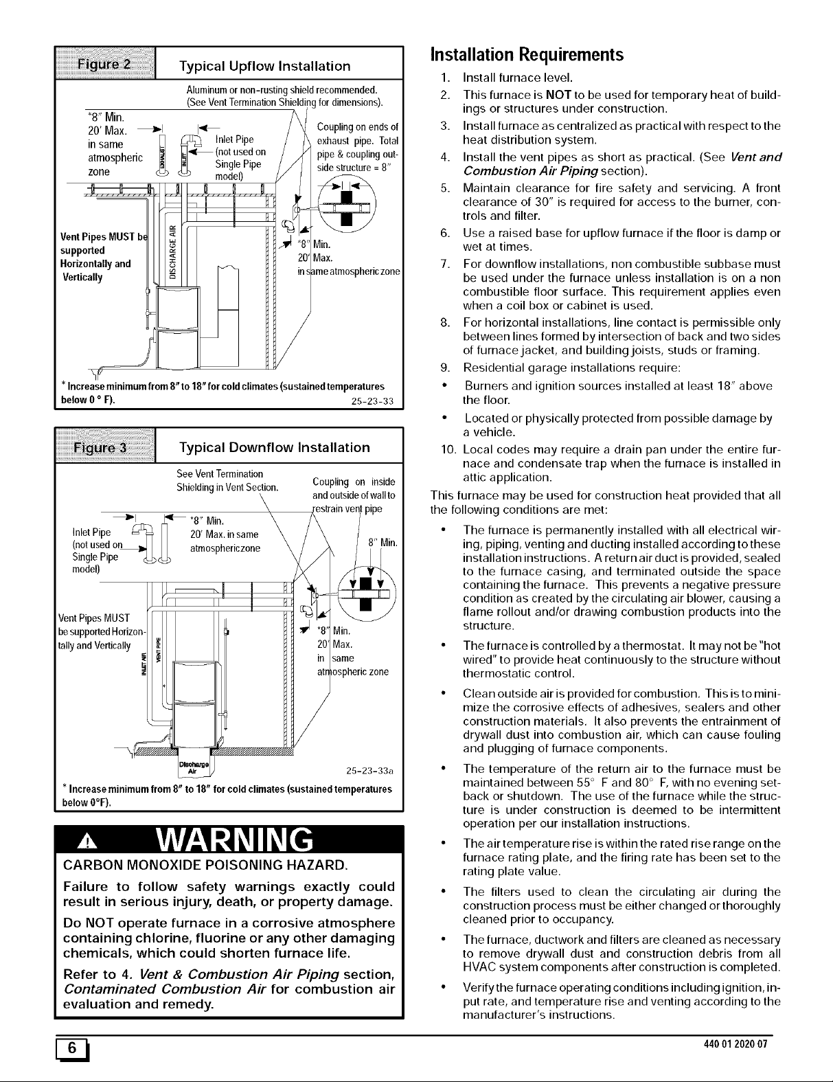
Typical Upflow Installation
Aluminum or non-rusting shield recommended.
(See Vent Termination Shielding for dimensions).
"8" Min.
20' Max. _1 I_
in same __ (notused on
atmospheric _iL. Single Pipe
zone _ model)
VentPipesMUST b_
supported
Horizontallyand
Vertically
Increaseminimumfrom8 to18 forcoldclimates(sustainedtemperatures
below0o F), 25-23-33
<_ _ InletPipe
Couplingon endsof
_iexhaust pipe. Total
pipe & couplingBut-
Typical Downflow Installation
See VentTermination
Shielding in Vent Section.
_1 _ "8" Min.
Inlet Pipe _ _ 20' Max.insame
(notused o_ _ atmosphedczone
Single Pipe_ <_
model)
VentPipes MUST
besupportedHorizon-
tallyand Vertically
* Increaseminimumfrom 8 to 18 forcoldclimates(sustained temperatures
below 0°F),
Coupling on inside
and outside of wall to
Min.
Max.
same
osphericzone
25-23-33a
CARBON MONOXIDE POISONING HAZARD.
Failure to follow safety warnings exactly could
result in serious injury, death, or property damage.
Do NOT operate furnace in a corrosive atmosphere
containing chlorine, fluorine or any other damaging
chemicals, which could shorten furnace life.
Refer to 4. Vent & Combustion Air Piping section,
Contaminated Combustion Air for combustion air
evaluation and remedy.
zone
Installation Requirements
1. Install furnace level.
2. This furnace is NOT to be used for temporary heat of build-
ings or structures under construction.
3. Install furnace as centralized as practical with respect to the
heat distribution system.
4. Install the vent pipes as short as practical. (See Vent and
Combustion Air Piping section).
5. Maintain clearance for fire safety and servicing. A front
clearance of 30" is required for access to the burner, con-
trols and filter.
6. Use a raised base for upflow furnace if the floor is damp or
wet at times.
7. For downflow installations, non combustible subbase must
be used under the furnace unless installation is on a non
combustible floor surface. This requirement applies even
when a coil box or cabinet is used.
8. For horizontal installations, line contact is permissible only
between lines formed by intersection of back and two sides
of furnacejacket, and buildingjoists, studs or framing.
9. Residential garage installations require:
• Burners and ignition sources installed at least 18" above
the floor.
• Located or physically protected from possible damage by
a vehicle.
10. Local codes may require a drain pan under the entire fur-
nace and condensate trap when the furnace is installed in
attic application.
This furnace may be used for construction heat provided that all
the following conditions are met:
• The furnace is permanently installed with all electrical wir-
ing, piping, venting and ducting installed according to these
installation instructions. A return air duct is provided, sealed
to the furnace casing, and terminated outside the space
containing the furnace. This prevents a negative pressure
condition as created by the circulating air blower, causing a
flame rollout and/or drawing combustion products into the
structure.
• The furnace is controlled by a thermostat. It may not be "hot
wired" to provide heat continuously to the structure without
thermostatic control.
• Clean outside air is provided for combustion. Thisisto mini-
mize the corrosive effects of adhesives, sealers and other
construction materials. It also prevents the entrainment of
drywall dust into combustion air, which can cause fouling
and plugging of furnace components.
• The temperature of the return air to the furnace must be
maintained between 55 ° F and 80 ° F, with no evening set-
back or shutdown. The use of the furnace while the struc-
ture is under construction is deemed to be intermittent
operation per our installation instructions.
• The air temperature rise iswithin the rated rise range on the
furnace rating plate, and the firing rate has been set to the
rating plate value.
• The filters used to clean the circulating air during the
construction process must be either changed or thoroughly
cleaned prior to occupancy.
• The furnace, ductwork and filters are cleaned as necessary
to remove drywall dust and construction debris from all
HVAC system components after construction is completed.
• Verify the furnace operating conditions including ignition, in-
put rate, and temperature rise and venting according to the
manufacturer's instructions.
[_ 440012020 07
Installation Positions
Leveling
This furnace can be installed in an upflow, horizontal (either left or
right) or downflow airflow position. DO NOT install this furnace on
its back. For the upflow position, the return air ductwork can be at-
tached to either the left or right side panel and/or the bottom. For
horizontal and downflow positions, the return air ductwork must be
attached to the bottom. The return air ductwork must never be at-
tached to the back of the furnace.
Furnace Installation Considerations
The installation of the furnace for a given application will dictate the
position of the furnace, the airflow, ductwork connections, vent and
combustion air piping. Consideration must be given to the follow-
ing:
Condensate Trap and Drain Lines
The supplied condensate trap must be attached to the furnace
side panel on either the left or right side. For horizontal installa-
tions, the drain trap is vertically attached to the side panel below
the furnace. A minimum clearance of 6" below the furnace is re-
quired for the condensate trap. Downward slope of the conden-
sate drain line from the condensate trap to the drain location must
be provided. Adequate freeze protection of the drain trap and the
drain line must be provided. See "Condensate Drain Trap"section
for further details.
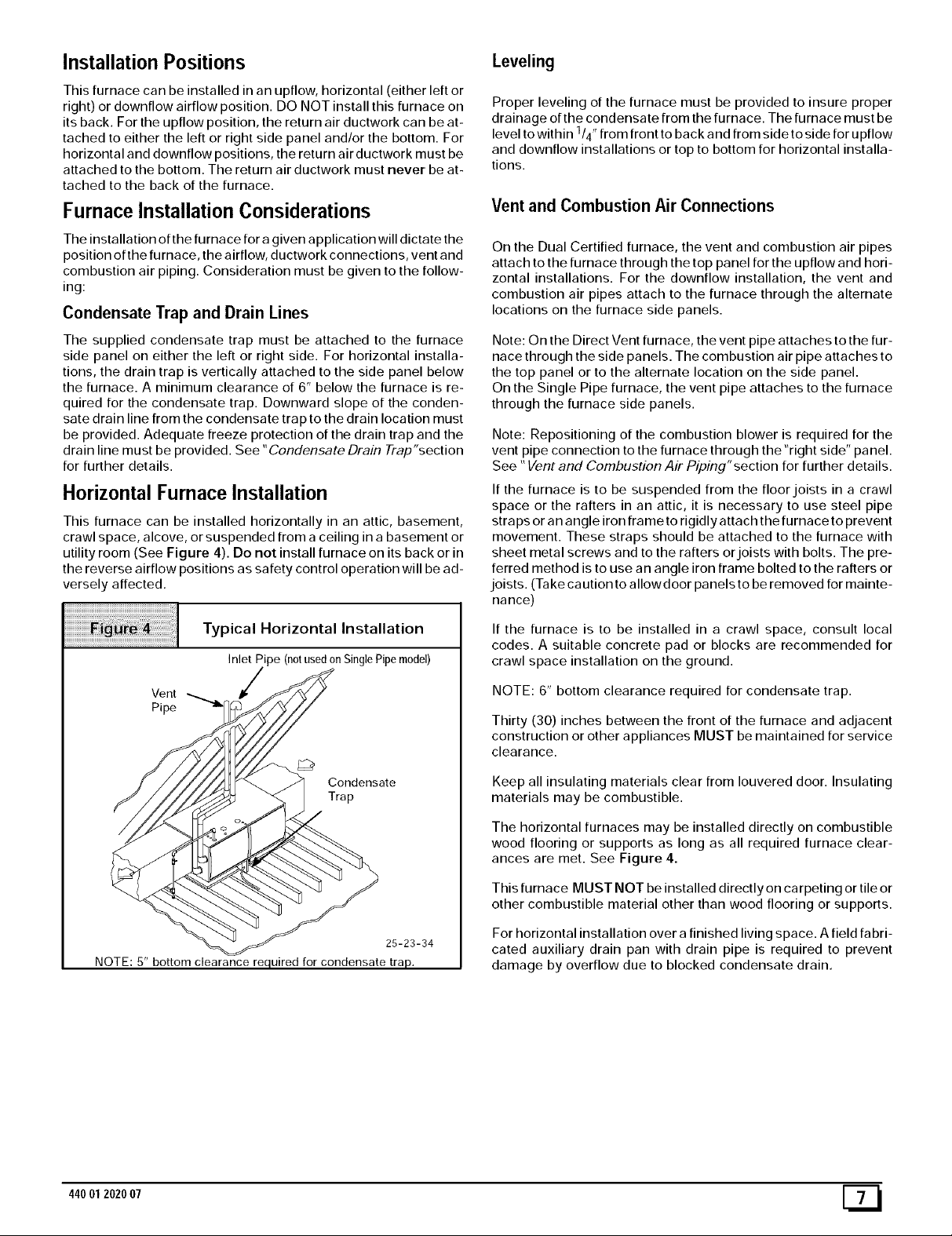
Horizontal Furnace Installation
This furnace can be installed horizontally in an attic, basement,
crawl space, alcove, or suspended from a ceiling in a basement or
utility room (See Figure 4). Do not install furnace on its back or in
the reverse airflow positions as safety control operation will be ad-
versely affected.
Proper leveling of the furnace must be provided to insure proper
drainage of the condensate from the furnace. The furnace must be
level to within 114"from front to back and from side to side for upflow
and downflow installations or top to bottom for horizontal installa-
tions.
Vent and Combustion Air Connections
On the Dual Certified furnace, the vent and combustion air pipes
attach to the furnace through the top panel for the upflow and hori-
zontal installations. For the downflow installation, the vent and
combustion air pipes attach to the furnace through the alternate
locations on the furnace side panels.
Note: On the Direct Vent furnace, the vent pipe attaches to the fur-
nace through the side panels. The combustion air pipe attaches to
the top panel or to the alternate location on the side panel.
On the Single Pipe furnace, the vent pipe attaches to the furnace
through the furnace side panels.
Note: Repositioning of the combustion blower is required for the
vent pipe connection to the furnace through the "right side" panel.
See "Vent and Combustion Air Piping"section for further details.
If the furnace is to be suspended from the floor joists in a crawl
space or the rafters in an attic, it is necessary to use steel pipe
straps or an angle iron frame to rigidly attach the furnace to prevent
movement. These straps should be attached to the furnace with
sheet metal screws and to the rafters or joists with bolts. The pre-
ferred method is to use an angle iron frame bolted to the rafters or
joists. (Take caution to allowdoor panels to be removed for mainte-
nance)
Typical Horizontal Installation
Inlet Pipe (notusedonSinglePipemodel)
Vent
Pipe
Condensate
Trap
25-23-34
NOTE: 5" bottom clearance required for condensate trap.
If the furnace is to be installed in a crawl space, consult local
codes. A suitable concrete pad or blocks are recommended for
crawl space installation on the ground.
NOTE: 6" bottom clearance required for condensate trap.
Thirty (30) inches between the front of the furnace and adjacent
construction or other appliances MUST be maintained for service
clearance.
Keep all insulating materials clear from Iouvered door. Insulating
materials may be combustible.
The horizontal furnaces may be installed directly on combustible
wood flooring or supports as long as all required furnace clear-
ances are met. See Figure 4.
This furnace MUST NOT be installed directly on carpeting or tile or
other combustible material other than wood flooring or supports.
For horizontal installation over a finished living space. A field fabri-
cated auxiliary drain pan with drain pipe is required to prevent
damage by overflow due to blocked condensate drain.
44001 2020 07 [_
3. Combustion 8, Ventilation Air
For Single Pipe Installation
(Non- Direct Vent)
CARBON MONOXIDE POISONING HAZARD
Failure to provide adequate combustion and
ventilation air could result in death and/or personal
injury.
Use methods described here to provide
combustion and ventilation air.
Furnaces require ventilation openings to provide sufficient air for
proper combustion and ventilation of flue gases. All duct or open-
ings for supplying combustion and ventilation air must comply with
National Fuel Gas Code, NFPA54/ANSI Z223.1, 2002 (or current
edition) and applicable provisions of local building codes.
Combustion and ventilation air must be supplied in accordance
with one of the following:
1. Section 8.3, Air for Combustion and Ventilation, ofthe Nation-
al Fuel Gas Code, National Fuel Gas Code (NFGC), ANSI
Z223.1-2002/NFPA 54-2002 in the U.S.,
2. Sections 7.2, 7.3, 7.5, 7.6, 7.7, and 7.8 of National Standard of
Canada, Natural Gas and Propane Installation Code
(NSCNGPIC), CSA B149.1-00 in Canada,
3. Applicable provisions of the local building code.
This furnace can NOT be common vented or connected to any
type B, BW or Lvent or vent connector, nor to any portion of a facto-
ry- built or masonry chimney. Ifthis furnace is replacing a previous-
ly common-vented furnace, it may be necessary to resize the
existing vent and chimney to prevent oversizing problems for the
other remaining appliance(s). See "Venting and Combustion Air
Check"in this section, This furnace MUST be vented to the out-
side.
When the installation is complete, check that all appliances have
adequate combustion air and are venting properly. See Venting
And Combustion Air Check in "5. Gas Vent Installation"Section in
this manual.
Outdoor Combustion Air Method
A space having less than 50 cubic feet per 1,000 BTUH input rating
for all gas appliances installed in the space requires outdoor air for
combustion and ventilation.
Air Openings andConnecting Ducts
1. Total maximum input ratings for all gas appliances in the
space MUST be considered when determining free area of
openings.
2. Connect ducts or openings directly to the outdoors.
3. When screens are used to cover openings, the openings
MUST be no smaller than 1/4" mesh.
4. The minimum dimension of air ducts MUST NOT be less
than 3".
5. When sizing grille, louver or screen, use the free area of
opening. If free area is NOT stamped or marked on grill or
louver, assume a 20 _ free area for wood and 60 _ for metal.
Screens shall have a mesh size not smaller than 1/4".
Requirements
1. Provide confined space with sufficient air for proper com-
bustion and ventilation of flue gases using horizontal or ver-
tical ducts or openings.
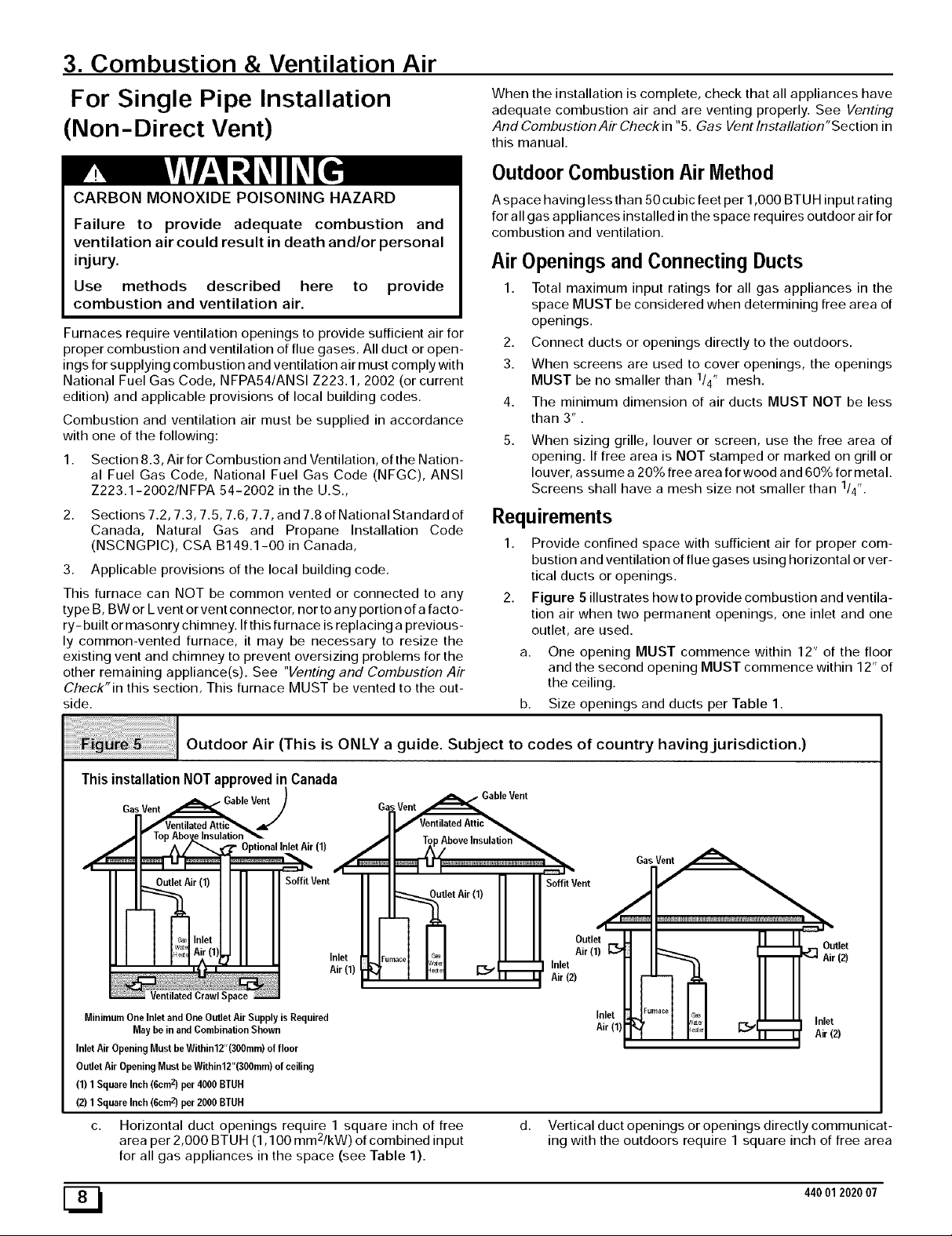
2. Figure 5 illustrates howto provide combustion and ventila-
tion air when two permanent openings, one inlet and one
outlet, are used.
a. One opening MUST commence within 12" of the floor
and the second opening MUST commence within 12" of
the ceiling.
b. Size openings and ducts per Table 1.
o o
Outdoor Air (This is ONLY a guide. Subject to codes of country having jurisdiction.)
ThisinstallationNOTapprovedin Canada
Gas Vent _able Ve_)
li'"-1 - I =:=J_
II I1 Soffit Vent
__ir (1) Soffit Vent
c_s Inlet
w_ Air (11 _ Inlet
I_÷ I Air(1)
Jentilated Crawl Space
Minimum One Inlet and One Outlet Air Supply is Required
May be in and Combination Shown
Inlet Air Opening Must be Within12"(300mm) of floor
Outlet Air Opening Must be Within12"(300mm) of ceiling
(1) 1 Square Inch (6cm z) per 4000 BTUH
(2) 1 Square Inch (6cm z) per 2000 BTUH
c. Horizontal duct openings require 1 square inch of free
a 2
rea per 2,000 BTUH (1,100 mm /kW) of combined input
for all gas appliances in the space (see Table 1).
F...... ('ia,_ L Air (1) _:_
r v_ _. Inlet
"_ _' _ _ Air (2)
11 Outlet
d. Vertical duct openings or openings directly communicat-
ing with the outdoors require 1 square inch of free area
ML
Inlet
Air(1)
:ld, I Eol Inlj] I r_=_l _ _ Airet(2)
44001 2020 07
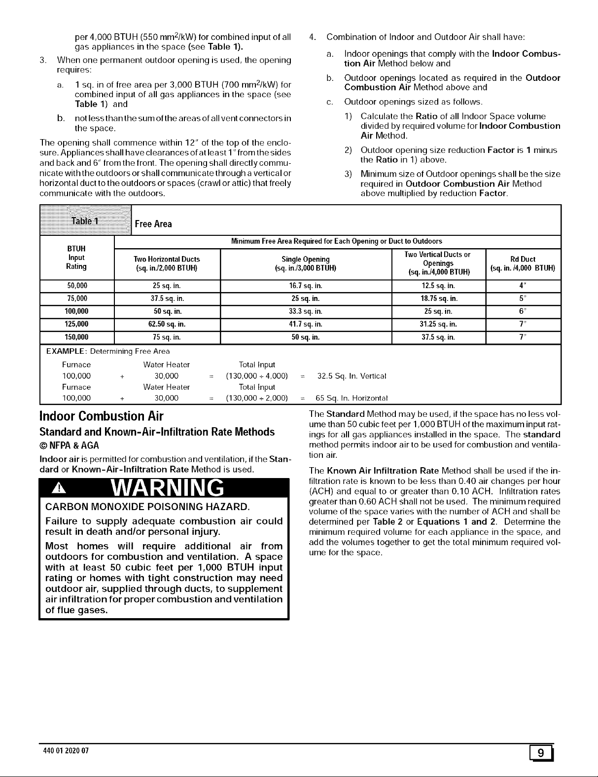
per 4,000 BTU H (550 mm2/kW) for combined input of all
gas appliances in the space (see Table 1).
3. When one permanent outdoor opening is used, the opening
requires:
a. 1 sq. in of free area per 3,000 BTUH (700 mm2/kW) for
combined input of all gas appliances in the space (see
Table 1) and
b. not less than the sum of the areas of all vent connectors in
the space.
The opening shall commence within 12" of the top of the enclo-
sure. Appliances shall have clearances of at least 1" from the sides
and back and 6" from the front. The opening shall directly commu-
nicate with the outdoors or shall communicate through a vertical or
horizontal duct to the outdoors or spaces (crawl or attic) that freely
communicate with the outdoors.
iiiiiiiiiiiiiiiiiiiiiiiiiiiiiiiiiiiiiiiiiiiiiiiiiiiiiiiiiiiiii_!!_!i_!_:!_!_¸iii_iiiiiiiiiiii_iiiiii_!_i_i_i_i_i_i_i_i_i_i_i_i_i_i_i_i_i_i_i_i_i_i_i_i_i_i_i_i_i_i_i_ii_!ii!iiiii¸iiiiii
i
FreeArea
4. Combination of Indoor and Outdoor Air shall have:
a,
Indoor openings that comply with the Indoor Combus-
tion Air Method below and
b.
Outdoor openings located as required in the Outdoor
Combustion Air Method above and
C.
Outdoor openings sized as follows.
1) Calculate the Ratio of all Indoor Space volume
divided by required volume for Indoor Combustion
Air Method.
2) Outdoor opening size reduction Factor is 1 minus
the Ratio in 1) above.
3) Minimum size of Outdoor openings shall be the size
required in Outdoor Combustion Air Method
above multiplied by reduction Factor.
BTUH
Input Two HorizontalDucts SingleOpening Openings (sq.in./4,000 BTUH)
Rating (sq.inJ2,000 BTUH) (sq.in./3,000BTUH) (sq.in./4,000 BTUH)
50,000 25 sq.in. 16.7sq. in. 12.5sq. in. 4"
75,000 37.5sq. in. 25 sq. in. 18.75sq. in. 5"
100,000 50 sq. in. 33.3sq. in. 25 sq. in. 6"
125,000 62.50 sq. in. 41.7sq. in. 31.25 sq. in. 7"
150,000 75 sq. in. 50sq. in. 37.5sq. in. 7"
EXAMPLE: Determining Free Area
Furnace Water Heater Total Input
100,000 + 30,000 (130,000 + 4,000) 32.5 Sq. In. Vertical
Furnace Water Heater Total Input
100,000 + 30,000 (130,000 + 2,000) 65 Sq. In. Horizontal
Indoor Combustion Air
Standard and Known-Air-Infiltration Rate Methods
© NFPA&AGA
Indoor air is permitted for combustion and ventilation, if the Stan-
dard or Known-Air-Infiltration Rate Method is used.
CARBON MONOXIDE POISONING HAZARD.
Failure to supply adequate combustion air could
result in death and/or personal injury.
Most homes will require additional air from
outdoors for combustion and ventilation. A space
MinimumFree Area Requiredfor EachOpening or Ductto Outdoors
TwoVerticalDuctsor Rd Duct
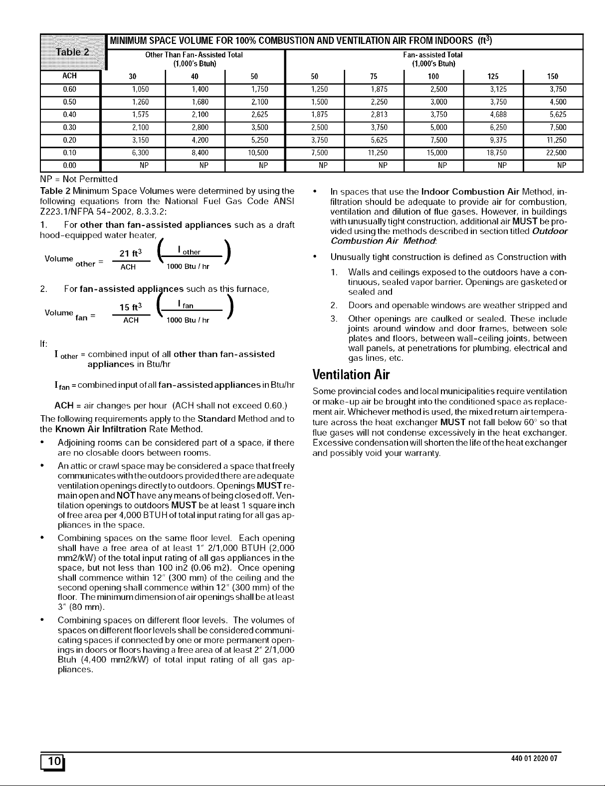
The Standard Method may be used, if the space has no less vol-
ume than 50 cubic feet per 1,000 BTUH of the maximum input rat-
ings for all gas appliances installed in the space. The standard
method permits indoor air to be used for combustion and ventila-
tion air.
The Known Air Infiltration Rate Method shall be used if the in-
filtration rate is known to be less than 0.40 air changes per hour
(ACH) and equal to or greater than 0.10 ACH. Infiltration rates
greater than 0.60 ACH shall not be used. The minimum required
volume of the space varies with the number of ACH and shall be
determined per Table 2 or Equations 1 and 2. Determine the
minimum required volume for each appliance in the space, and
add the volumes together to get the total minimum required vol-
ume for the space.
with at least 50 cubic feet per 1,000 BTUH input
rating or homes with tight construction may need
outdoor air, supplied through ducts, to supplement
air infiltration for proper combustion and ventilation
of flue gases.
44001 2020 07 [_
MINIMUMSPACEVOLUMEFOR100%COMBUSTIONANDVENTILATIONAIRFROMINDOORS(ft 3)
OtherThan Fan-AssistedTotal Fan-assistedTotal
(1,OOO'sBtuh)
ACH
0.60
0.50
0.40
0.30
0.20
0.I0
0.00
NP = Not Permitted
Table 2 Minimum Space Volumes were determined by using the
following equations from the National Fuel Gas Code ANSI
Z223.1/NFPA 54-2002, 8.3.3.2:
1. For other than fan-assisted appliances such as a draft
hood-equipped water heater,
Volume other - 21 ft3 _k I other )
2. For fan-assisted appliances such as this furnace,
Volume
If:
The following requirements apply to the Standard Method and to
the Known Air Infiltration Rate Method.
• Adjoining rooms can be considered part of a space, if there
• An attic or crawl space may be considered a space that freely
• Combining spaces on the same floor level. Each opening
• Combining spaces on different floor levels. The volumes of
fan
[ other = combined input of all other than fan-assisted
appliances in Btu/hr
[ fan = combined input of all fan-assisted appliances in Btu/hr
ACH = air changes per hour (ACH shall not exceed 0.60.)
are no closable doors between rooms.
communicates with the outdoors provided there are adequate
ventilation openings directly to outdoors. Openings MUST re-
main open and NOT have any means of being closed off. Ven-
tilation openings to outdoors MUST be at least I square inch
of free area per 4,000 BTU H of total input rating for all gas ap-
pliances in the space.
shall have a free area of at least 1" 2/1,000 BTUH (2,000
mm2/kW) of the total input rating of all gas appliances in the
space, but not less than 100 in2 (0.06 m2). Once opening
shall commence within 12" (300 ram) of the ceiling and the
second opening shall commence within 1 2" (300 ram) of the
floor. The minimum dimension of air openings shall be at least
3" (80 ram).
spaces on different floor levels shall be considered communi-
cating spaces if connected by one or more permanent open-
ings in doors or floors having a free area of at least 2" 2/1,000
Btuh (4,400 mm2/kW) of total input rating of all gas ap-
pliances.
30
1,050
1260
1,575
2,100
3,150
6,300
NP
I 40
1,400
1,680
2,100
2,800
4,200
8,400 10,500 7,500 11250 15,000
NP NP NP NP NP
/ \
ACH 1000Btu / hr
15 ft 3 _, I fan
ACH 1000 Btu / hr
/
50
1,750
2,100
2,625
3,500
5,250
)
(1,000'sBtuh)
50
1250
1,500
1,875
2,500
3,750
In spaces that use the Indoor Combustion Air Method, in-
filtration should be adequate to provide air for combustion,
ventilation and dilution of flue gases. However, in buildings
with unusually tight construction, additional air MUST be pro-
vided using the methods described in section titled Outdoor
Combustion Air Method:
• Unusually tight construction is defined as Construction with
1. Walls and ceilings exposed to the outdoors have a con-
2. Doors and openable windows are weather stripped and
3. Other openings are caulked or sealed. These include
75
1,875
2,250
2,813
3,750
5,625
tinuous, sealed vapor barrier. Openings are gasketed or
sealed and
joints around window and door frames, between sole
plates and floors, between wall-ceiling joints, between
wall panels, at penetrations for plumbing, electrical and
gas lines, etc.
100
2,500
3,000
3,750
5,000
7,500
125
3,125
3,750
4,688
6,250
9,375
18,750
NP
150
3,750
4,500
5,625
7,500
11250
22,500
Ventilation Air
Some provincial codes and local municipalities require ventilation
or make-up air be brought into the conditioned space as replace-
ment air. Whichever method is used, the mixed return air tempera-
ture across the heat exchanger MUST not fall below 60 ° so that
flue gases will not condense excessively in the heat exchanger.
Excessive condensation will shorten the life of the heat exchanger
and possibly void your warranty.
NP
[_ 440012020 07
Venting and Combustion Air Check
The following information is supplied to allow the installer to make
adjustments to the setup of existing appliances, IF REQUIRED,
based on good trade practices, local codes, and good judgement
of the installer. Manufacturer does NOT take responsibility for
modifications made to existing equipment.
NOTE: If this installation replaces an existing furnace from a
commonly vented system, the original venting system may no lon-
ger be sized to properly vent the attached appliances. An improp-
erly sized venting system may cause the formation of condensate
in the vent and the leakage or spillage of vent gases. To make sure
there is adequate combustion air for all appliances, MAKE THE
FOLLOWING CHECK.
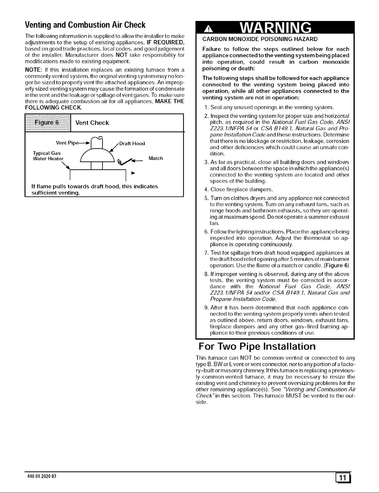
Vent Check
,,-,q
Vent Pipe--'_l I_ S Draft Hood
Typical Gas f "_
Water Heater ( I I %Vii...._ Match
I I
If flame pulls towards draft hood, this indicates
sufficient venting.
CARBON MONOXIDE POISONING HAZARD
Failure to follow the steps outlined below for each
appliance connected to the venting system being placed
into operation, could result in carbon monoxide
poisoning or death:
The following steps shall be followed for each appliance
connected to the venting system being placed into
operation, while all other appliances connected to the
venting system are not in operation:
1. Seal any unused openings in the venting system.
2. Inspect the venting system for proper size and horizontal
pitch, as required in the National Fuel Gas Code, ANSI
Z223. 1/NFPA 54 or CSA B149.1, Natural Gas and Pro-
pane Installation Code and these instructions. Determine
that there is no blockage or restriction, leakage, corrosion
and other deficiencies which could cause an unsafe con-
dition.
3. As far as practical, close all building doors and windows
and all doors between the space in which the appliance(s)
connected to the venting system are located and other
spaces of the building.
4. Close fireplace dampers.
5. Turn on clothes dryers and any appliance not connected
to the venting system. Turn on any exhaust fans, such as
range hoods and bathroom exhausts, so they are operat-
ing at maximum speed. Do not operate a summer exhaust
fan.
6. Followthe lighting instructions. Placethe appliance being
inspected into operation. Adjust the thermostat so ap-
pliance is operating continuously.
7. Test for spillage from draft hood equipped appliances at
the draft hood relief opening after 5 minutes of main burner
operation. Use the flame of a match or candle. (Figure 6)
8. If improper venting is observed, during any of the above
tests, the venting system must be corrected in accor-
dance with the National Fuel Gas Code, ANSI
Z223.1/NFPA 54 and/or CSA B149. 1, Natural Gas and
Propane Installation Code.
9. After it has been determined that each appliance con-
nected to the venting system properly vents when tested
as outlined above, return doors, windows, exhaust fans,
fireplace dampers and any other gas-fired burning ap-
pliance to their previous conditions of use.
For Two Pipe Installation
This furnace can NOT be common vented or connected to any
type B, BW or Lvent or vent connector, nor to a ny portion of a facto-
ry-built or masonry chimney. If this furnace is replacing a previous-
ly common-vented furnace, it may be necessary to resize the
existing vent and chimney to prevent oversizing problems for the
other remaining appliance(s). See "Venting and Combustion Air
Check"in this section, This furnace MUST be vented to the out-
side.
44001 2020 07 [_1
4. Vent and Combustion Air Piping
CARBON MONOXIDE POISONING HAZARD.
Failure to properly vent this furnace could result in
death and/or personal injury.
Use methods described here to provide combustion
and ventilation air.
Dual Certified (*9MPT & *9MPV Models)
This furnace is certified as a category IV appliance and is fan as-
sisted. A catefory IV appliance is a direct vent central furnace
which operates with a positive vent static pressure and a flue loss
less than 17%. This furnace can be installed as a direct vent fur-
nace using outside air for combustion or the furnace can use air
from inside the structure for combustion. The INLET air pipe is op-
tional. If combustion air comes from inside the structure, adequate
make up air MUST be provided to compensate for oxygen burned.
See Confined Space Installation in the Combustion and Ven-
tilation Air chapter. If combustion air is drawn from outside the
structure, it MUST be taken from the same atmospheric pressure
zone as the vent pipe.
Contaminated Combustion Air
Installations in certain areas or types of structures could cause ex-
cessive exposure to contaminated air having chemicals or halo-
gens that will result in safety and performance related problems
and may harm the furnace. These instances must use only out-
door air for combustion.
The following areas or types of structures may contain or have ex-
posure to the substances listed below. The installation must be
evaluated carefully as it may be necessary to provide outdoor air
for combustion.
• Commercial buildings.
• Buildings with indoor pools.
• Furnaces installed in laundry rooms.
• Furnaces installed in hobby or craft rooms.
• Furnaces installed near chemical storage areas.
• Permanent wave solutions for hair.
• Chlorinated waxes and cleaners.
• Chlorine based swimming pool chemicals.
• Water softening chemicals.
• De-icing salts or chemicals.
• Carbon tetrachloride.
• Halogen type refrigerants.
• Cleaning solvents (such as perchloroethylene).
• Printing inks, paint removers, varnishes, etc..
• Hydrochloric acid.
• Sulfuric Acid.
• Solvent cements and glues.
• Antistatic fabric softeners for clothes dryers.
• Masonry acid washing materials.
Ventand Combustion Air Piping Guidelines
This furnace is approved for venting with Schedule 40 PVC,
CPVC, ABS, Cellular Core pipe fittings and SDR-26 PVC.
NOTE: All PVC, CPVC, ABS, and Cellular Core pipe fittings, sol-
vent cement, primers and procedures must conform to American
National Standard Institute and American Society for Testing and
Materials (ANSI/ASTM) standards.
• Pipe and Fittings (in Italics)- ASTM D1785, D2241,
D2466, D2661, D2665, F-891, F-628.
• PVC Primer and Solvent Cement (in Italics)- ASTM
D2564.
• Procedure for Cementing Joints (in Italics)- Ref ASTM
D2855.
NOTE: All vent piping MUST be installed in compliance with local
codes or ordinances, these instructions, good trade practices, and
codes of country having jurisdiction.
1. Determine the best routing and termination for the vent pipe
and air inlet pipe by referring to all of the instructions and
guidelines in this Section.
2. Determine the size required for the vent pipe and air inlet
pipe.
3. Loosely assemble all venting parts without adhesive (pipe
joint cement) for correct fit before final assembly.
4. Use of vertical piping is preferred because there will be
some moisture in the flue gases that may condense as it
leaves the vent pipe (See Speciallnstruction ForHorizontal
Vents).
5. The vertical vent pipe MUST be supported so that no weight
is allowed to rest on the combustion blower.
6. Exhaust vent piping or air inlet piping diameter MUST NOT
be reduced.
7. All exhaust vent piping from the furnace to termination
MUST slope upwards. A minimum of 1/4" per foot of run is
required to properly return condensate to the furnace drain
system.
8. Use DWV type long radius elbows whenever possible, as
they provide for the minimum slope on horizontal runs and
they provide less resistance in the vent system. If DWV el-
bows cannot be used, use two, 45 ° elbows when possible.
On horizontal runs the elbows can be slightly misaligned to
provide the correct slope.
9. All horizontal pipe runs MUST be supported at least every
five feet with galvanized strap or other rust resistant materi-
al. NO sags or dips are permitted.
10. All vertical pipe runs MUST be supported every six feet
where accessible.
11. The maximum pipe length is 40' total in the inlet oroutlet
side of the system. Upto five, 90° elbows can be used on the
inlet orthe outlet. With the Concentric Vent Termination Kits
(NAHAO01CV or NAHAOO2CV), the maximum pipe length
is 35' with 4 90° elbows. If more elbows are required, reduce
the length of both the inlet and exhaust pipes 5' for each
additional elbow used. (See Table 3 or Table 4).
12. The minimum pipe run length is 2'.
13. The piping can be run in the same chase or adjacent to sup-
ply or vent pipe for water supply or waste plumbing. It can
also be run in the same chase with a vent from another 90+
furnace.
NOTE: In NO case can the piping be run in a chase where
temperatures can exceed 140 ° F. or where radiated heat
from adjacent surfaces would exceed 140 ° F.
14. The vent outlet MUST be installed to terminate in the same
atmospheric pressure zone as the combustion air inlet.
15. The vent system can be installed in an existing unused
chimney provided that:
• Both the exhaust vent and air intake run the length of the
chimney.
• No other gas fired appliance or fireplace (solid fuel) is
vented into the chimney.
44001 2020 07
• The top of the chimney MUST be sealed flush or crowned
up to seal against rain or melting snow so ONLY the piping
protrudes.
• The termination clearances shown in Figure 7 are main-
tained.
16. Furnace applications with vertical vents requiring vent di-
ameter increaser fittings must have increaser fittings
installed in vertical portion of the vent. Condensate will be
trapped in the vent if the vent diameter is increased prior to
having an elbow turned upward. This could cause nuisance
tripping of the pressure switch.
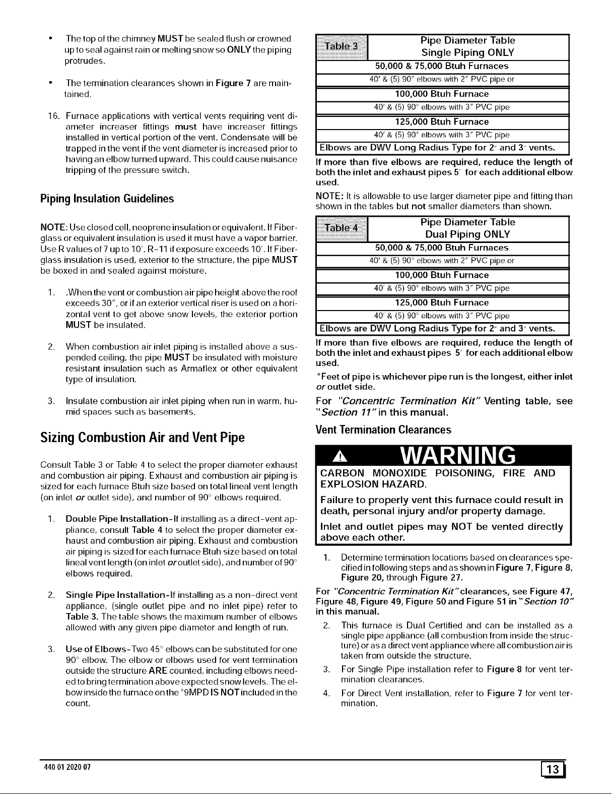
Piping InsulationGuidelines
Pipe Diameter Table
Single Piping ONLY
50,000 & 75,000 Btuh Furnaces
40' & (5) 90 ° elbows with 2" PVC pipe or
100,000 Btuh Furnace
40' & (5) 90° elbows with 3" PVC pipe
125,000 Btuh Furnace
40' & (5) 90° elbows with 3" PVC pipe
Elbows are DWV Long Radius Type for 2" and 3" vents.
If more than five elbows are required, reduce the length of
both the inlet and exhaust pipes 5' for each additional elbow
used.
NOTE: It is allowable to use larger diameter pipe and fitting than
shown in the tables but not smaller diameters than shown.
NOTE: Use closed cell, neoprene insulation or equivalent. If Fiber-
glass or equivalent insulation is used it must have a vapor barrier.
Use Rvalues of 7 upto 10', R-11 if exposure exceeds 10'. If Fiber-
glass insulation is used, exterior to the structure, the pipe MUST
be boxed in and sealed against moisture.
1,
.When the vent or combustion air pipe height above the roof
exceeds 30", or if an exterior vertical riser is used on a hori-
zontal vent to get above snow levels, the exterior portion
MUST be insulated.
2,
When combustion air inlet piping is installed above a sus-
pended ceiling, the pipe MUST be insulated with moisture
resistant insulation such as Armaflex or other equivalent
type of insulation.
3. Insulate combustion air inlet piping when run in warm, hu-
mid spaces such as basements.
Sizing Combustion Air andVentPipe
Consult Table 3 or Table 4 to select the proper diameter exhaust
and combustion air piping. Exhaust and combustion air piping is
sized for each furnace Btuh size based on total lineal vent length
(on inlet or outlet side), and number of 90 ° elbows required.
1,
Double Pipe Installation-If installing as a direct-vent ap-
pliance, consult Table 4 to select the proper diameter ex-
haust and combustion air piping. Exhaust and combustion
air piping is sized for each furnace Btuh size based on total
lineal vent length (on inlet oroutlet side), and number of 90 °
elbows required.
2,
Single Pipe Installation-If installing as a non-direct vent
appliance, (single outlet pipe and no inlet pipe) refer to
Table 3. The table shows the maximum number of elbows
allowed with any given pipe diameter and length of run.
3, Use of Elbows-Two 45° elbows can be substituted for one
90 ° elbow. The elbow or elbows used for vent termination
outside the structure ARE counted, including elbows need-
ed to bring termination above expected snow levels. The el-
bow inside the furnace on the *9MPD IS NOT included in the
count.
Ta_i _ Pipe Diameter Table
Dual Piping ONLY
50,000 & 75,000 Btuh Furnaces
40' & (5) 90 ° elbows with 2" PVC pipe or
100,000 Btuh Furnace
40' & (5) 90° elbows with 3" PVC pipe
125,000 Btuh Furnace
40' & (5) 90° elbows with 3" PVC pipe
Elbows are DWV Long Radius Type for 2" and 3" vents.
If more than five elbows are required, reduce the length of
both the inlet and exhaust pipes 5' for each additional elbow
used.
*Feet of pipe is whichever pipe run is the longest, either inlet
or outlet side.
For "Concentric Termination Kit" Venting table, see
"Section 11" in this manual.
Vent Termination Clearances
CARBON MONOXIDE POISONING, FIRE AND
EXPLOSION HAZARD.
Failure to properly vent this furnace could result in
death, personal injury and/or property damage.
Inlet and outlet pipes may NOT be vented directly
above each other.
1. Determine termination locations based on clearances spe-
cified in following steps and as shown in Figure 7, Figure 8,
Figure 20, through Figure 27.
For "Concentric Termination Kit" clearances, see Figure 47,
Figure 48, Figure 49, Figure 50 and Figure 51 in "Section 10"
in this manual.
This furnace is Dual Certified and can be installed as a
single pipe appliance (all combustion from inside the struc-
ture) or as a direct vent appliance where all combustion air is
taken from outside the structure.
3. For Single Pipe installation refer to Figure 8 for vent ter-
mination clearances.
4. For Direct Vent installation, refer to Figure 7 for vent ter-
mination.
44001 202007 [_
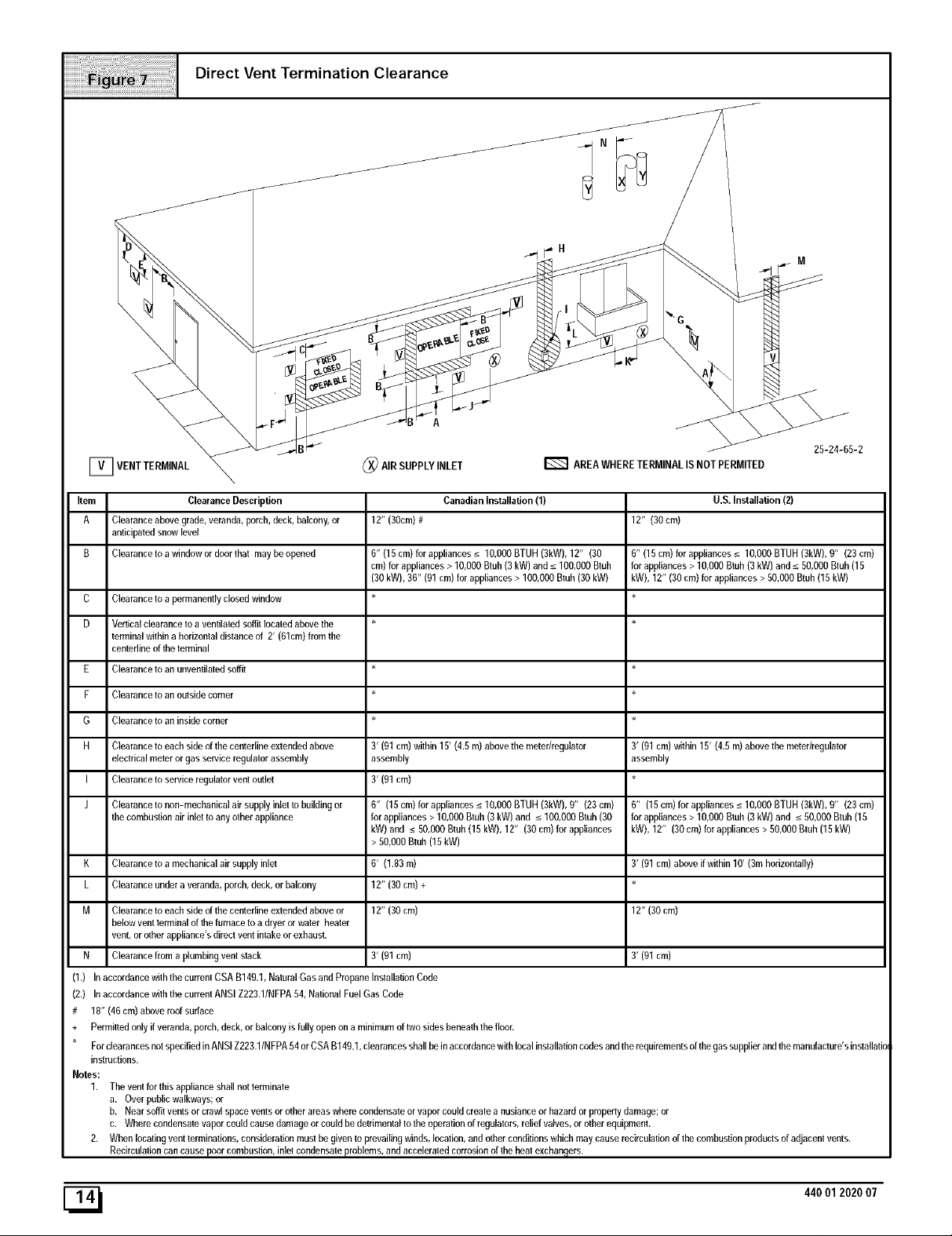
Item Clearance Description
A Clearance above grade, veranda, porch, deck, balcony, or
anticipated snow level
B Clearance to a window or door thai may be opened
C Clearance to a permanently closed window
D Vertical clearance to a ventilated soffit located above the
terminal within a horizontal distance of 2' (61cm) from the
centedine of the terminal
E Clearance to an unventilated soffit
P Clearance to an outside corner
G Clearance to an inside comer
H Clearance to each side of the centefline extended above
electrical meter or gas service regulator assembly
I Clearance to service regulator vent outlet
J Clearance to non-mechanical air supply inlet _o building or
the combustion air inlet to any other appliance
Canadian Installation (1)
12" (30cm)#
6" (15 cm) for appliances _< 10,000 BTUH (3kW), 12" (30
cm) for appliances > 10,000 Btuh (3 kW) and _<100,000 Btuh
(30 kW), 36" (91 cm) for appliances > 100,000 Btub (30 kW)
3' (91 cm) within 15' (4.5 m) above the meter/regulator
assembly
3' (91 cm)
6" (15cm)forappliances_<10,000BTUH(3kW),0" (23cm)
forappliances> 10,000Btuh (3 kW) and _<100,000Btuh(30
kW) and _<50,000Btuh(15kW), 12" (30 cm)for appliances
12" (30cm)
6" (15 cm) for appliances _< 10,000 BTUH (3kW), 0" (23 cm)
for appliances > 10,000 Bmh (3 kW) and _<50,000 Btuh (15
kW), 12" (30 cm) for appliances > 50,000 Btuh (15 kW)
3' (91 cm) within 15' (4.5 m) above the meter/regulator
assembly
6" (15cm)forappliances_<lO,OOOBTUH (3kW),O" (23cm)
for appliances > 10,000 Btuh (3 kW) and _<50,000 Btuh (15
kW), 12" (30 cm) for appliances > 50,000 Bluh (15 kW)
U.S. Installation (2)
> 50,000Bmh(15kW)
K Clearance to a mechanical air supply inlet
L Clearance under a veranda, porch, deck, or balcony
M Clearance to each side of the centefline extended above or
below vent terminal of the furnace to a dryer or water heater
vent, or other appliance's direct vent intake or exhaust.
N Clearance from a plumbing vent stack 3' (91 cm)
(1.) In accordance with the currem CSA B149.1, Natural Gas and Propane Installation Code
(2,) In accordance w0h the current ANSI Z223.1/NFPA 54, National Fuel Gas Code
# 18" (46 cm) above roof surface
+ Permitted only if veranda, porch, deck, or balcony is fully open on a minimum of two sides beneath the floor.
For deara nces not specified in AN SI Z223.1/N FPA 54 or CSA B149,1, clearances shall be in accordance with local installation codes and the requirements of the gas supplier and the manufacture's installatie
instructions.
Notes:
1. The vent for this appliance shall not terminate
a. Over public walkways; or
b. Near soffit vents or crawl space vents or other areas where condensate or vapor could create a nusiance or hazard or property damage; or
c. Where condensate vapor could cause damage or could be detrimental to the operation of regulalors, relief valves, or other equipment.
2. When locating vent lerminations, consideration must be given to prevailing winds, location, and other conditions which may cause recirculation of the combustion products of adjacent vents.
Recircula0on can cause poor combustion, inlet condensate problems, and accelerated corrosion of the heal exchangers.
6' (1.83m)
12" (30 cm) +
12" (30 cm)
3' (91 cm) above if within 10' (3m horizontally)
12" (30 cm)
3' (91 cm)
[_ 440012020 07
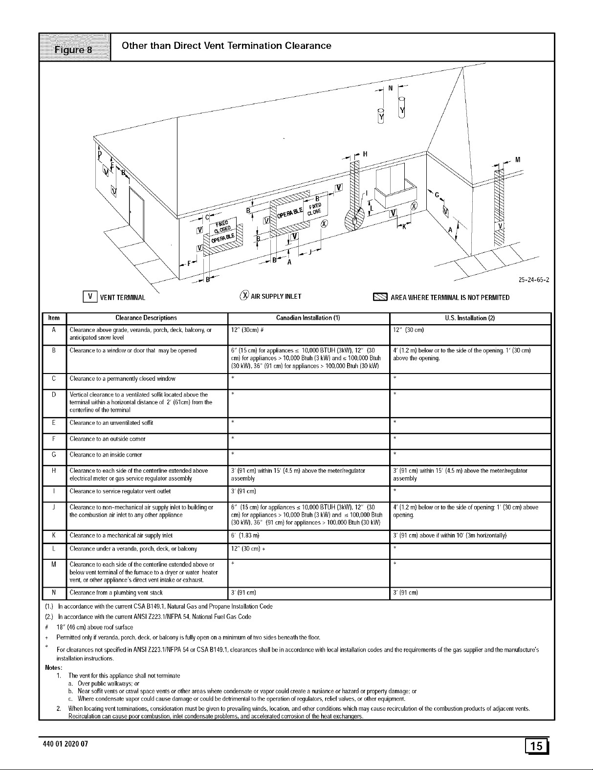
Other than Direct Vent Termination Clearance
Item Clearance Descriptions
A Clearance above grade, veranda, porch, deck, balcony, or
anticipated snow level
B Clearance to a window or door thai may be opened
C
Clearance to a permanently closed window
D
Vertical clearance to a ventilated soffit located above the *
terminal within a horizontal distance of 2' (61cm) from the
centerline of the terminal
Clearance to an unventilated soffit *
F Clearance to an outside corner *
G Clearance to an inside comer *
H Clearance to each side of the centedine extended above
eleclrical meter or gas service regulator assembly
I Clearance to service regulator vent outlet
J Clearance to non-mechanical air supply inlel to building or
the combustion air inlet to any other appliance
K Clearance to a mechanical air supply inlel
L Clearance under a veranda, porch, deck, or balcony
M Clearance to each side of the centedine extended above or *
below vent terminal of the furnace to a dryer or water heater
vent, or other appliance's direct vent intake or exhaust.
N Clearance from a plumbing vent stack
(1.) In accordance with the current CSA B149.1, Natural Gas and Propane Installation Code
(2.) In accordance wilh the current ANSI Z223.1/NFPA 04, National Fuel Gas Cede
# 18" (46 cm) above roof surface
+ Permitted only if veranda, porch, deck, or balcony is fully open on a minimum of two sides beneath the floor.
For clearances not specified in ANSI Z223.1/NFPA 04 or CSA B140.1, clearances shall be in accordance with local installalion codes and the requirements of the gas supplier and the manufacture's
installation instructions.
Notes:
1. The vent for this appliance shall not terminale
a. Over public walkways; or
b. Near soffit vents or crawl space venta or other areas where condensate or vapor could create a nusiance or hazard or property damage; or
c. Where condensate vapor could cause damage or could be detrimental to the operafion of regulalors, relief valves, or other equipmenL
2. When locating vent terminations, consideration must be given to prevailing winds, location, and other conditions which may cause recirculation of the combustion products of adjacent vents.
Recirculafion can cause poor combustion, inlet condensate problems, and acceleraled corrosion of the heat exchangers.
12" (30cm)#
0" (10 cm) for appliances _< 10,000 BTUH (3kW), 12" (30
cm) for appliances > 10,000 Btuh (3 kW) and _<100,000 Btuh
(30 kW), 30" (01 cm) for appliances > 100,000 Btuh (30 kW)
3' (91 cm) within 15' (4.5 m) above the meter/regulator
assembly
3' (91 cm)
6" (15cm)forappliances_<10,OOOBTUH(3kW),12" (30
cm)forappliances> 10,000Btuh(3kW) and _<100,000Btuh
(30 kW),30" (91 cm) for appliances> 100,000Btuh(30 kW)
6' (1.83m)
12" (30 cm) +
3' (91 cm)
Canadian Installation (1)
U.S.Installation(2)
12" (30cm)
4' (1.2 m) below or to the side of the opening, 1' (30 cm)
above the opening.
3' (01 cm) within 15' (4.5 m) above the meter/regulator
assembly
4' (1.2 m) below or to the side of opening: 1' (30 cm) above
opening.
3' (91 cm) above if within 10' (3m horizontally)
3' (91 cm)
44001 202007
CondensateDrainTrap
This furnace removes both sensible and latent heat from the prod-
ucts of combustion. Removal of the latent heat results in con-
densation of the water vapor. The condensate is removed from the
furnace through the drains in the plastic transition and the vent fit-
ting. The drains connect to the factory installed internally mounted
condensate drain trap on the left or right side of the furnace.
The startup of a new furnace will involve a cycle or two of the fur-
nace to properly prime the condensate trap with water. Until the
trap is fully primed, some condensate will be pulled into the com-
bustion blower. The furnace may cycle on the pressure switch con-
nected to the plastic transition box due to condensate buildup.
After the trap is primed, the condensate will start draining from the
furnace. The combustion blower will clear out any remaining con-
densate in the blower housing through the vent fitting downstream
of the blower. Note that the condensate trap can also be primed by
pouring water into the 1/2" drain hose. Remove the1/2" ID drain
hose from either the gutter or the white PVC Tee Trap. Using a fun-
nel pour eight (8) ounces of water into 1/2" ID drain hose.Water will
flow through the drain hose and into the condensate drain trap.
This will prime both the vent and the transition sides of the trap. Re-
connect the 1/2, ID drain hose to the original component, either the
gutter or the PVC Tee Trap.
The condensate drain trap supplied with the furnace MUST be
used. The drain connection on the condensate drain trap is sized
for 3/4" PVC or CPVC pipe, however alternate 1/2" CPVC (nominal
5/8" O.D.) or vinyl tubing with a minimum inner diameter (I.D.) of
5/8" may also be used, as allowed by local codes. Alternate drain
pipes and hoses may be used as allowed by local codes.
The drain line must maintain a 1/4" per foot downward slopetoward
the drain. 1/4" per foot is recommended. Installation of an overflow
line is recommended when the 1/4" per foot slope to the conden-
sate drain cannot be maintained. See Figure 18 for proper routing
and installation of the overflow.
DO NOT trap the drain line in any other location than at the con-
densate drain trap supplied with the furnace.
If possible DO NOT route the drain line where it may freeze. The
drain line must terminate at an inside drain to prevent freezing of
the condensate and possible property damage.
A condensate sump pump MUST be used if required by lo-
cal codes, or if no indoor floor drain is available. The con-
densate pump must be approved for use with acidic
condensate.
2. A plugged condensate drain line or a failed condensate
pump will allow condensate to spill. If the furnace is installed
where a condensate spill could cause damage, it is recom-
mended that an auxiliary safety switch be installed to pre-
vent operation of the equipment in the event of pump failure
or plugged drain line. If used, an auxiliary safety switch
should be installed in the R circuit (low voltage) ONLY.
3. If the auxiliary switch in the condensate pump is used, the
furnace may shut down dueto a blocked condensate line or
failed pump. To prevent frozen water pipes see the "Frozen
Water Pipe Hazard" section on Page 4 of this manual.
FROZEN AND BURST WATER PIPE HAZARD
Failure to do so could result in burst water pipes,
serious property damage and/or personal injury.
If a condensate pump is installed, a plugged
condensate drain or a failed pump may cause the
furnace to shut down. Do not leave the home
unattended during freezing weather without turning
off water supply and draining water pipes or
otherwise protecting against the risk of frozen pipes.
Condensate Drain Trap Freeze Protection
Special precautions MUST be made if installing furnace in an area
which may drop below freezing. This can cause improper opera-
tion or damage to the equipment. If the the furnace environment
has the potential of freezing, the drain trap and drain line must be
protected. Use 3 to 6 watt per foot at 115 volt, 40 ° F self-regulating
shielded and waterproof heat tape. Wrap the drain trap and drain
line with the heat tape and secure with the ties. Follow the heat
tape manufacturer's recommendations.
[_ 440012020 07
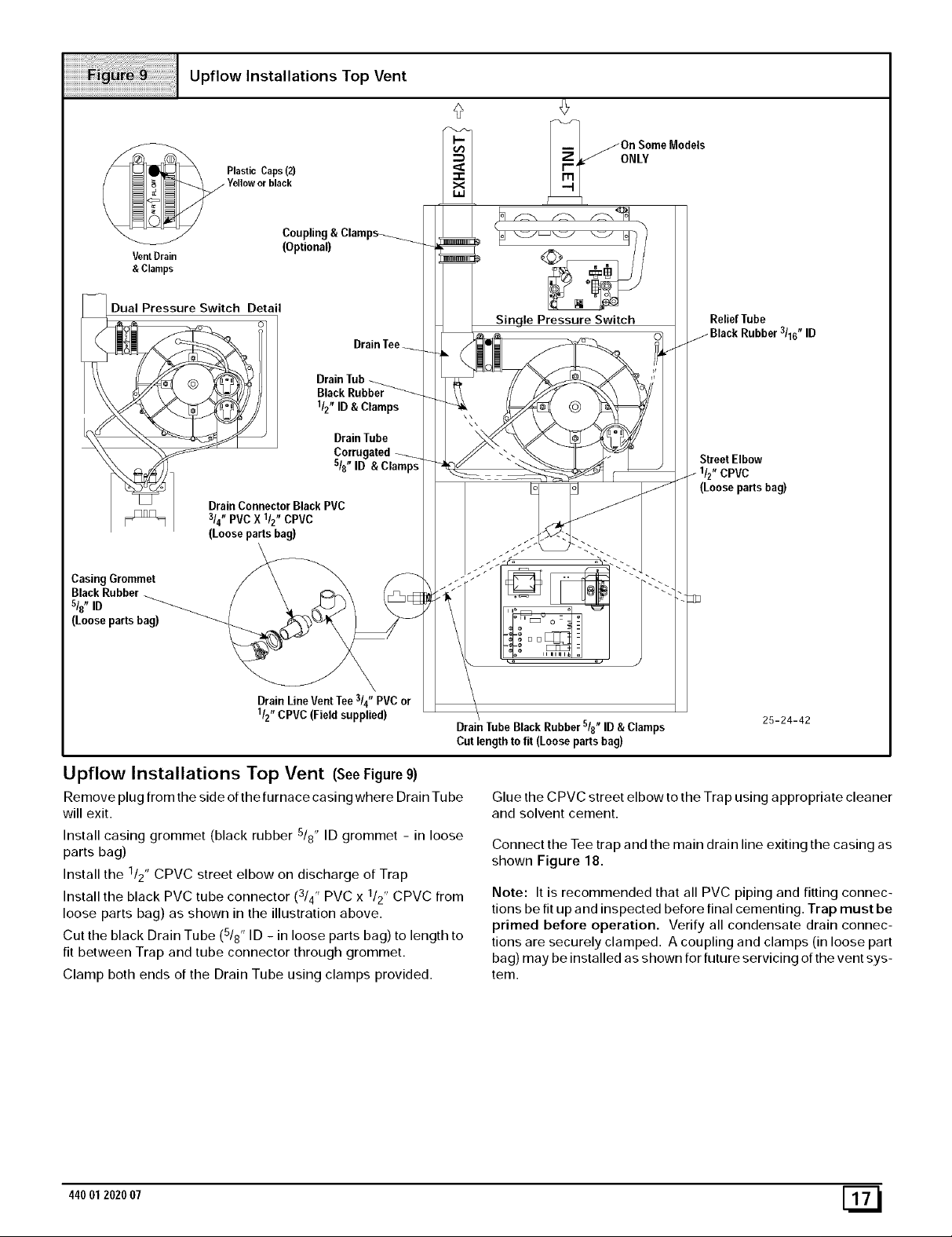
Upflow Installations Top Vent
/On Some Models
ONLY
Vent Drain
& Clamps
Dual Pressure Switch Detail
_ __ Drainfub_
"_ _ _/_ sis" ID
_] DrainConnector Black PVC
p_],==l / 3/4"PVCX l/z" CPVC
Casing Grommet
BlackRubber
s/8" ID
(Looseparts bag)
(Looseparts bag)
(Optional)
Corrugate
\
Drain LineVentTee314"PVC or
1/2"CPVC(Field supplied)
Drain TubeBlack Rubbers/8" ID &Clamps
Cut length to fit (Loose partsbag)
25-24-42
Upflow Installations Top Vent (SeeFigure 9)
Remove plug from the side of the furnace casing where Drain Tu be
will exit.
Install casing grommet (black rubber 5/8" ID grommet - in loose
parts bag)
Install the 1/2" CPVC street elbow on discharge of Trap
Install the black PVC tube connector (3/4" PVC x 1/2" CPVC from
loose parts bag) as shown in the illustration above.
Cut the black Drain Tube (5/8" ID - in loose parts bag) to length to
fit between Trap and tube connector through grommet.
Clamp both ends of the Drain Tube using clamps provided.
44001 202007 [_
Glue the CPVC street elbow to the Trap using appropriate cleaner
and solvent cement.
Connect the Tee trap and the main drain line exiting the casing as
shown Figure 18.
Note: It is recommended that all PVC piping and fitting connec-
tions be fit up and inspected before final cementing. Trap must be
primed before operation. Verify all condensate drain connec-
tions are securely clamped. A coupling and clamps (in loose part
bag) may be installed as shown for future servicing of the vent sys-
tem.
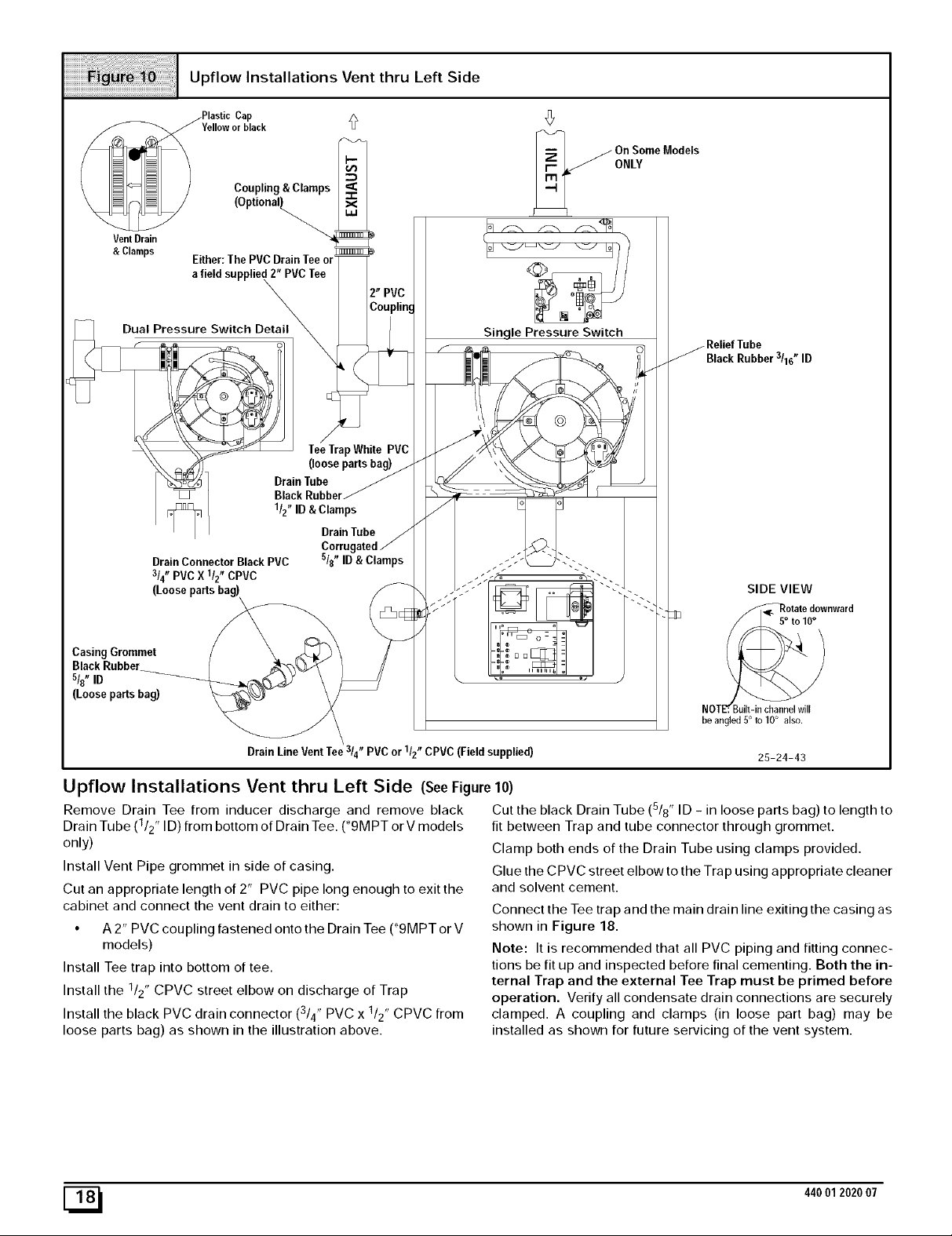
Upflow Installations Vent thru Left Side
/Plastic Cap
Yelloworblack
Coupling & Clamps
VentDrain
&Clamps Either:ThePVC DrainTee or
afield supplied 2" PVCTee
\
On SomeModels
ONLY
Dual Pressure Switch Detail_
CasingGrommet
s/{' ID
(Loosepartsbag)
DrainTube
BlackRubbel
1/2"ID& Clamps
DrainConnector BlackPVC
3/4"PVCX 1/2"CPVC
(Loosepartsbag)
DrainLineVentTee /4 PVC or /2 CPVC (Fieldsupplied)
TeeTrapWhite PVC
(loosepartsbag)
DrainTube
s/{' ID& Clamps
3 t_ 1 n
Sin qle Pressure Switch
BlackRubber3/16"ID
SIDE VIEW
FF_otate downward
NOTF. Buell-in channel will
be angled 5° to 10° also.
25-24-43
Upflow Installations Vent thru Left Side (SeeFigure10)
Remove Drain Tee from inducer discharge and remove black
Drain Tube (1/2" ID) from bottom of Drain Tee. (*9MPT or V models
only)
Install Vent Pipe grommet in side of casing.
Cut an appropriate length of 2" PVC pipe long enough to exit the
cabinet and connect the vent drain to either:
• A 2" PVC coupling fastened onto the Drain Tee (*9MPT or V
models)
Install Tee trap into bottom of tee.
Install the 112" CPVC street elbow on discharge of Trap
Install the black PVC drain connector (3/4" PVC x 1/2" CPVC from
loose parts bag) as shown in the illustration above.
[_ 440012020 07
Cut the black Drain Tube (5/8" ID - in loose parts bag) to length to
fit between Trap and tube connector through grommet.
Clamp both ends of the Drain Tube using clamps provided.
Glue the CPVC street elbow to the Trap using appropriate cleaner
and solvent cement.
Connect the Tee trap and the main drain line exiting the casing as
shown in Figure 18.
Note: It is recommended that all PVC piping and fitting connec-
tions be fit up and inspected before final cementing. Both the in-
ternal Trap and the external Tee Trap must be primed before
operation. Verify all condensate drain connections are securely
clamped. A coupling and clamps (in loose part bag) may be
installed as shown for future servicing of the vent system.
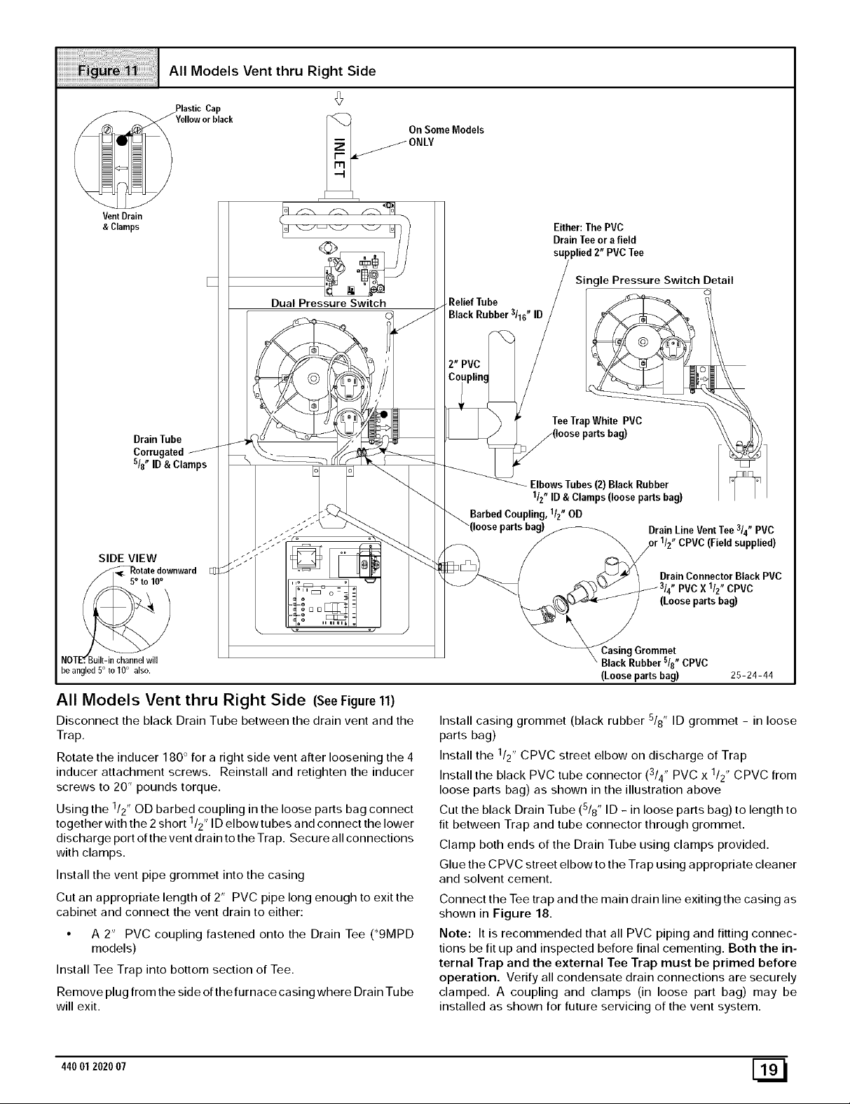
All Models Vent thru Right Side
On Some Models
VentDrain
& Clamps
Drain Tube
Corrugated
sl8" ID & Clamps
SIDE VIEW
/_Rotat e downward
Dual Pressure Switch
,ReliefTube
BlackRubber3/16"ID
Barbed Cot
Either:The PVC
Drain Teeor a field
supplied 2" PVC Tee
Single Pressure Switch Detail
TeeTrapWhite PVC
Elbows Tubes (2) Black Rubber
1/2" ID & Clamps (loose parts bag)
I, llz" OD
Drain Line Vent Tee 3/4" PVC
CPVC (Field supplied)
DrainConnector Black PVC
PVCX 1/2"CPVC
(Loosepartsbag)
NOTE'r. Built-in channel will
he angled 5° to 10° also.
All Models Vent thru Right Side (SeeFigure 11)
Disconnect the black Drain Tube between the drain vent and the
Trap.
Rotate the inducer 180 ° for a right side vent after loosening the 4
inducer attachment screws. Reinstall and retighten the inducer
screws to 20" pounds torque.
Using the /2' OD barbed coupling in the loose parts bag connect
together with the 2 short /2' ID elbowtubes and connect the lower
discharge port of the vent drain to the Trap. Secure all connections
with clamps.
Install the vent pipe grommet into the casing
Cut an appropriate length of 2" PVC pipe long enough to exit the
cabinet and connect the vent drain to either:
• A 2" PVC coupling fastened onto the Drain Tee (_9MPD
Install Tee Trap into bottom section of Tee.
Remove plug from the side of the furnace casing where Drain Tube
will exit.
1 ,
1 ,
models)
Grommet
BlackRubber5/8"CPVC
(Loosepartsbag) 25-24-44
Install casing grommet (black rubber 5/8" ID grommet - in loose
parts bag)
Install the 1/2" CPVC street elbow on discharge of Trap
Install the black PVC tube connector ( /4' PVC x 1/2" CPVC from
3 ,
loose parts bag) as shown in the illustration above
Cut the black Drain Tube (5/8" ID - in loose parts bag) to length to
fit between Trap and tube connector through grommet.
Clamp both ends of the Drain Tube using clamps provided.
Glue the CPVC street elbow to the Trap using appropriate cleaner
and solvent cement.
Connect the Tee trap and the main drain line exiting the casing as
shown in Figure 18.
Note: It is recommended that all PVC piping and fitting connec-
tions be fit up and inspected before final cementing. Both the in-
ternal Trap and the external Tee Trap must be primed before
operation. Verify all condensate drain connections are securely
clamped. A coupling and clamps (in loose part bag) may be
installed as shown for future servicing of the vent system.
44001 2020 07 [_
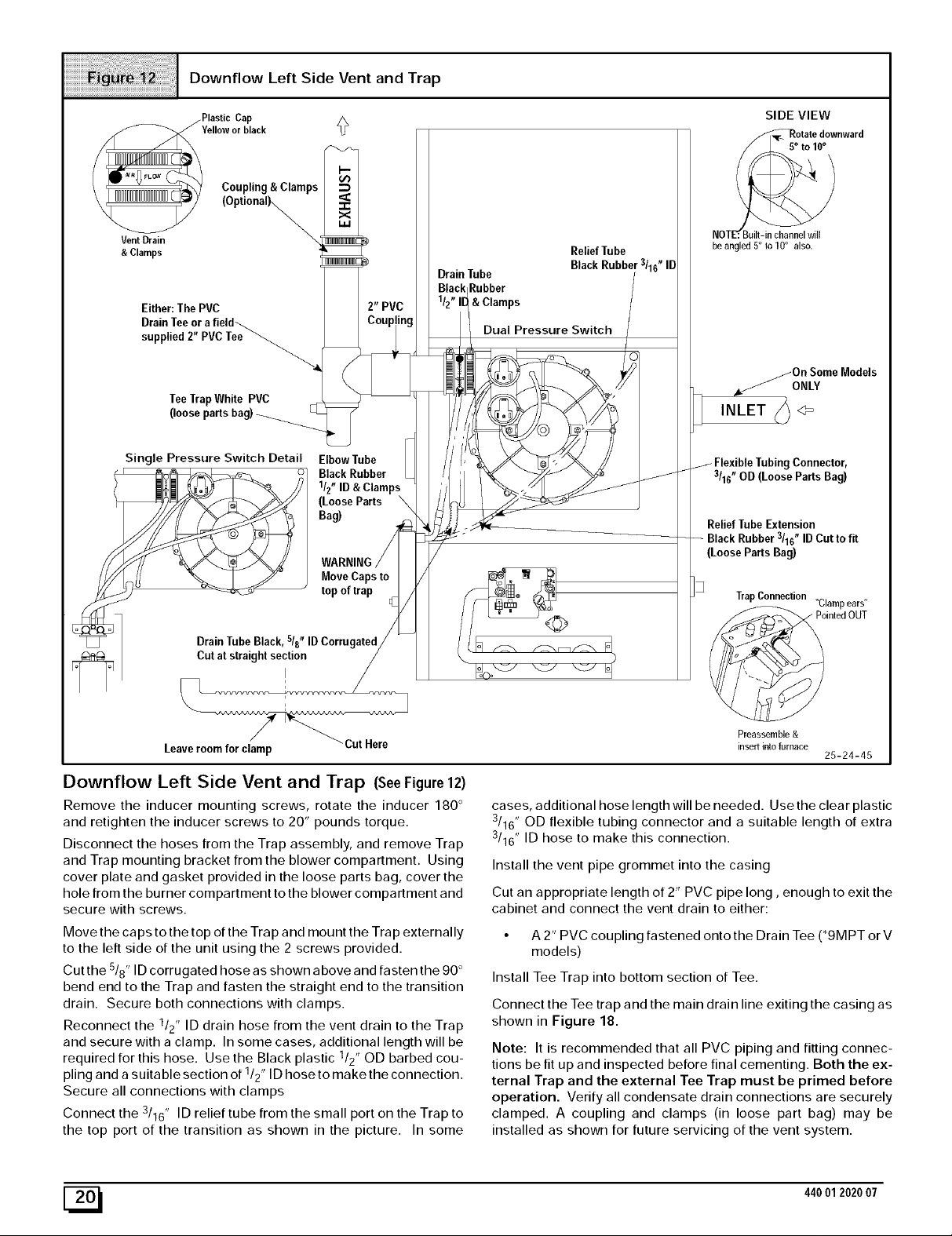
Downflow Left Side Vent and Trap
Cap
Yellowor black
Coupling & Clamps
VentDrain
&Clamps
(Optionally,,
Either: The PVC
TeeTrapWhite PVC
(looseparts
Single Pressure Switch Detail Elbow Tube
1/2"ID& Clamps
(LooseParts \
Bag)
BlackRubber
WARNING
MoveCaps to
top of trap
DrainTube
Rubber
& Clamps
Dual Pressure Switch
Relief Tube
SIDE VIEW
_o otatedownward
o 10°
NOT_
be angled 5° to10° also.
/On SomeModels
,/ONLY
INLET h 4=
Connector,
3/16" OD (Loose Parts Bag)
Relief Tube Extension
Rubber 3/16" ID Cut to fit
(Loose Parts Bag)
TrapConnection "Clampears"
DrainTubeBlack, sis" IDCorrugated
Cut at straight section
I
Leaveroom for clamp
Cut Here
Downflow Left Side Vent and Trap (SeeFigure 12)
Remove the inducer mounting screws, rotate the inducer 180 °
and retighten the inducer screws to 20" pounds torque.
Disconnect the hoses from the Trap assembly, and remove Trap
and Trap mounting bracket from the blower compartment. Using
cover plate and gasket provided in the loose parts bag, cover the
hole from the burner compartment to the blower compartment and
secure with screws.
Move the caps to the top of the Trap and mount the Trap externally
to the left side of the unit using the 2 screws provided.
Cut the 5/8" ID corrugated hose as shown above and fasten the 90 °
bend end to the Trap and fasten the straight end to the transition
drain. Secure both connections with clamps.
Reconnect the 1/2" ID drain hose from the vent drain to the Trap
and secure with a clamp. In some cases, additional length will be
required for this hose. Use the Black plastic 1/2" OD barbed cou-
pling and a suitable section of 1/2" ID hose to make the connection.
Secure all connections with clamps
Connect the 3/16" ID relief tube from the small port on the Trap to
the top port of the transition as shown in the picture. In some
ointedOUT
Preassemble &
insert into furnace
25-24-45
cases, additional hose length will be needed. Use the clear plastic
3/16" OD flexible tubing connector and a suitable length of extra
3/16" ID hose to make this connection.
Install the vent pipe grommet into the casing
Cut an appropriate length of 2" PVC pipe long, enough to exit the
cabinet and connect the vent drain to either:
• A 2" PVC coupling fastened onto the Drain Tee (*9MPT or V
models)
Install Tee Trap into bottom section of Tee.
Connect the Tee trap and the main drain line exiting the casing as
shown in Figure 18.
Note: It is recommended that all PVC piping and fitting connec-
tions be fit up and inspected before final cementing. Both the ex-
ternal Trap and the external Tee Trap must be primed before
operation. Verify all condensate drain connections are securely
clamped. A coupling and clamps (in loose part bag) may be
installed as shown for future servicing of the vent system.
[_ 440012020 07
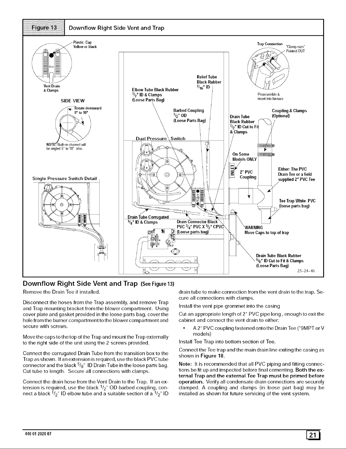
Downflow Right Side Vent and Trap
Vent Drain
& Clamps
SIDE VIEW
_Rotate downward
NOTE'r. Built-in channel will
he angled 5° to 10° also.
Single Pressure Switch Detail
Elbow Tube BlackRubber
1/2"ID &Clamps
(LoosePartsBag)
BarbedCoupling
1/2"OD
(Loose Parts Bag)
Dual Switch
Relief Tube
Black Rubber
3116" ID
Drain Tube
Black Rubber
1/2" ID Cut to Fi
Trap Connection
Preassemble &
insert inlo furnace
Coupling & Clamps
(Optional)
Either: ThePVC
Drain Teeor a field
DrainTubeCorrugated
s/8"ID& Clamps
Downflow Right Side Vent and Trap (SeeFigure 13)
Remove the Drain Tee if installed.
Disconnect the hoses from the Trap assembly, and remove Trap
and Trap mounting bracket from the blower compartment. Using
cover plate and gasket provided in the loose parts bag, cover the
hole from the burner compartment to the blower compartment and
secure with screws.
Move the caps to the top of the Trap and mount the Trap externally
to the right side of the unit using the 2 screws provided.
Connect the corrugated Drain Tube from the transition box to the
Trap as shown. If an extension is required, use the black PVC tube
connector and the black 5/8" ID Drain Tube in the loose parts bag.
Cut tube to length. Secure all connections with clamps.
Connect the drain hose from the Vent Drain to the Trap. If an ex-
tension is required, use the black 1/2" OD barbed coupling, con-
nect a black 1/2" ID elbow tube and a suitable section of a 1/2" ID
TeeTrapWhite PVC
(loosepartsbag)
MoveCaps to topof trap
DrainTube Black Rubber
_"ID Cutto Fit & Clamps
(LooseParts Bag)
25-24-46
drain tube to make connection from the vent drain to the trap. Se-
cure all connections with clamps.
Install the vent pipe grommet into the casing
Cut an appropriate length of 2" PVC pipe long, enough to exit the
cabinet and connect the vent drain to either:
• A 2" PVC coupling fastened onto the Drain Tee (*9MPT or V
models)
Install Tee Trap into bottom section of Tee.
Connect the Tee trap and the main drain line exiting the casing as
shown in Figure 18.
Note: It is recommended that all PVC piping and fitting connec-
tions be fit up and inspected before final cementing. Both the ex-
ternal Trap and the external Tee Trap must be primed before
operation. Verify all condensate drain connections are securely
clamped. A coupling and clamps (in loose part bag) may be
installed as shown for future servicing of the vent system.
44001 2020 07 [_
 Loading...