

Page 1
INSTRUCTION MANUAL
COMMUNICATIONS RECEIVER FOR COMPUTER
iPCR1000
This device complies with Part 15 of the FCC Rules. Operation is subject to the following two conditions: (1) This device may not cause
harmful interference, and (2) this device must accept any interference
received, including interference that may cause undesired operation.
Page 2
IMPORTANT
WORD DEFINITION
RWARNING
Personal injury, fire hazard or electric shock
may occur.
CAUTION
Equipment damage may occur.
NOTE
If disregarded, inconvenience only. No risk
of personal injury, fire or electric shock.
FEATURES
READ ALL INSTRUCTIONS and on-line help care-
fully and completely before using the receiver.
SAVE THIS INSTRUCTION MANUAL — This
instruction manual contains important operating instructions
for the IC-PCR1000 COMMUNICATIONS RECEIVER FOR
COMPUTER.
USE antenna(s), such as a well-matched 50 Ω antenna and
feedline. For radio communications, the antenna is of critical
importance, along with sensitivity.
EXPLICIT DEFINITIONS
Icom, Icom Inc. and are registered trademarks of Icom Incorporated
(Japan) in the United States, United Kingdom, Germany, France, Spain, Russia
and/or other countries.
i
• USER-SELECTABLE INTERFACE
Users can choose from 3 different operating screens depending on their ability level and preference.
• WIDE FREQUENCY RANGE, MULTI-MODE RECEIVE
The IC-PCR1000 has a wide frequency coverage from 0.5
MHz to 1300 MHz* with all mode receive capability.
* Some frequency ranges are restricted depending on version.
• IF SHIFT
The IF shift function is effective in SSB mode for reducing interference from nearby signals. It does so by electronically
shifting the passband of the IF filter.
• REAL-TIME BANDSCOPE FUNCTION
The real-time bandscope function makes it easy to find busy
frequencies and also easy to observe receive frequency band
conditions. The maximum band width is ±200 kHz.
• NOISE BLANKER •VSC (Voice Scan Control) FUNCTION
• S-METER SQUELCH • HIGH PERFORMANCE PLL
CIRCUIT • A VARIETY OF TUNING STEPS • A VARIETY OF
SCANS • DIGITAL AFC CIRCUIT
Versions of the IC-PCR1000 which display “CE” on the serial
number seal, comply with the essential requirements of the
89/336/EEC directive for Electromagnetic Compatibility.
Page 3

PRECAUTION
RWARNING! NEVER connect the receiver to an AC
outlet. This may pose a fire hazard or result in an electric
shock.
NEVER connect other than the specified AC adapter to the
receiver. This connection will ruin the receiver.
NEVER connect the receiver to a power source of more
than 16 V DC such as a 24 V battery. This connection will ruin
the receiver.
NEVER allow children to touch the receiver.
NEVER expose the receiver to rain, snow or any liquids.
DO NOT use or place the receiver in areas with tempera-
tures below 0°C (+32°F) or above +50°C (+122°F) or, in
areas subject to direct sunlight.
AVOID placing the receiver in excessively dusty environ-
ments.
AVOID the use of chemical agents such as benzine or al-
cohol when cleaning, as they damage the receiver surfaces.
Microsoft®and Windows®are registered trademarks of Microsoft Corporation in
the U.S.A and other countries. Screen shots produced with permission from
Microsoft Corporation. All other products or brands are registered trademarks
or trademarks of their respective holders.
For U.S.A. only (FCC information)
CAUTION: Changes or modifications to this receiver, not
expressly approved by Icom Inc., could void your authority to operate
this receiver under FCC regulations.
Class B digital device users
This equipment has been tested and found to comply with the limits
for a Class B digital device, pursuant to Part 15 of the FCC Rules.
These limits are designed to provide reasonable protection against
harmful interference in a residential installation. This equipment generates, uses and can radiate radio frequency energy and, if not installed and used in accordance with the instructions, may cause
harmful interference to radio communications. However, there is no
guarantee that interference will not occur in a particular installation. If
this equipment does cause harmful interference to radio or television
reception, which can be determined by turning the equipment off and
on, the user is encouraged to try to correct the interference by one or
more of the following measures:
- Reorient or relocate the receiving antenna.
- Increase the separation between the equipment and receiver.
- Connect the equipment into an outlet on a circuit different from that
to which the receiver is connected.
- Consult the dealer or an experienced radio/TV technician for help.
For Canada only
Operation is subject to the following two conditions: (1) this device
may not cause interference, and (2) this device must accept any interference, including interference that may cause undesired operation of the device.
ii
Page 4

SYSTEM REQUIREMENTS
TABLE OF CONTENTS
• An RS-232C serial port (38400 bps or faster)
• Microsoft®Windows®98/98SE/Me/2000/XP
• At least 10 MB of hard disk space
• 640 ✕ 480 pixel display
(800 ✕ 600 pixel display recommended)
IMPORTANT ……………………………………………………………i
EXPLICIT DEFINITIONS ………………………………………………i
FEATURES ………………………………………………………………i
PRECAUTION …………………………………………………………ii
SYSTEM REQUIREMENTS …………………………………………iii
TABLE OF CONTENTS ………………………………………………iii
1 INSTALLATION ……………………………………………………1–7
■ Hardware installation ………………………………………………1
■ Antenna installation ………………………………………………2
■ Grounding …………………………………………………………2
■ AF output level selection …………………………………………3
■ TNC connection ……………………………………………………4
■ Software installation ………………………………………………5
■ Uninstallation ………………………………………………………6
■ Starting the IC-PCR1000 …………………………………………7
■ Serial port setting …………………………………………………7
2 PANEL DESCRIPTION …………………………………………8–12
■ Component screen…………………………………………………8
■ Radio screen………………………………………………………12
■ Communications receiver screen ………………………………12
3 SPECIFICATIONS………………………………………………13–14
4 SUPPLIED ACCESORIES AND OPTIONS ……………………15
■ Supplied accesories………………………………………………15
■ Options ……………………………………………………………15
iii
Page 5
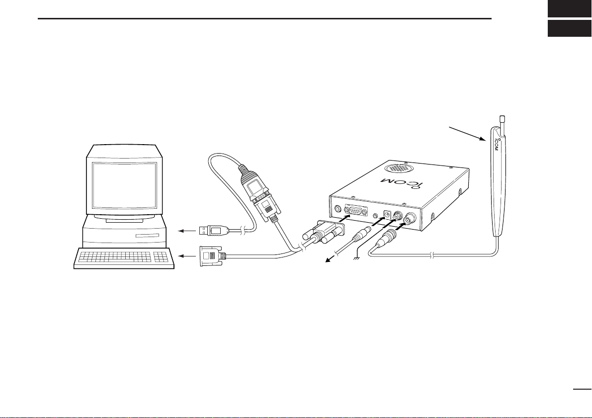
■ Hardware installation
Refer to the diagram below for connections.
USB serial adapter cable
to an
USB port
INSTALLATION
Remove the protective
sheet and attach to
a specified place.
iC-pcr1000
UNICATIONS RECEIVER
COMM
1
Personal computer
* When using the USB serial adapter cable, USB serial port can be used.
It is necessary to USB driver installation. The driver is supplied with the USB
serial adapter cable.
to an
RS-232C port
to an AC adapter
Ground
1
Page 6
1
INSTALLATION
■ Antenna installation
Antennas play a very important role in receiver operation.
Connecting a poor quality antenna to the IC-PCR1000 will result in less than optimum performance.
Select antenna(s), such as a well-matched 50 Ω antenna and
feedline. 1.5:1 of Voltage Standing Wave Ratio (VSWR) is
recommended for a desired band. Of course, the antenna line
should be a coaxial cable.
CAUTION: Protect your receiver from lightning by
using a lightning arrestor.
NOTE: The supplied antenna is a simple plain antenna which
may not obtain indicated specifications. To obtain maximum
performance from the IC-PCR1000, you must purchase an
external wide band antenna such as an optional Icom
AH-7000 (25–1300 MHz), etc.
Contact your nearest Icom Dealer or Service Center for regarding optimum antenna locations.
The antenna connector type is BNC, so an adapter may
be necessary to connect an optional antenna.
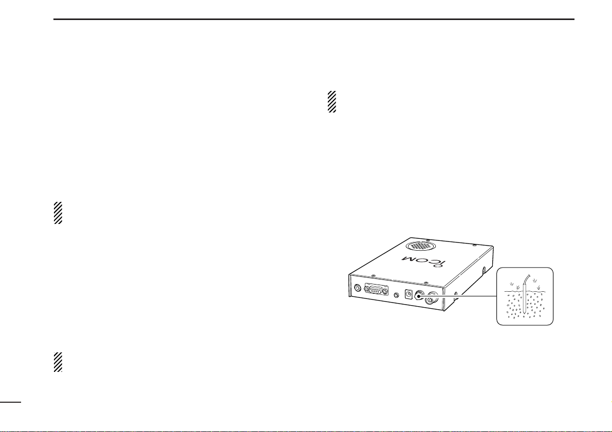
■ Grounding
R WARNING: NEVER use a gas pipe or electrical
conduit pipe for grounding.
To prevent accidents involving electricity and interference
from computers, ground the receiver through the GROUND
terminal on the rear panel.
For best results, connect a heavy gauge cable to a water pipe
or long, earth-sunk copper rod. Make the distance between
the [GND] terminal and ground as short as possible.
EIVER
EC
ICATIONS R
iC-pcr1000
MUN
OM
C
2
Page 7

INSTALLATION
1
■ AF output level selection
The received audio can be input into your computer via the
sound card.
Before inputting the received audio into the [LINE IN] connector (connector name depends on your sound card), the
output level of the [EXT-SP] must be set properly. Perform as
follows:
q Remove the 8 screws from the cover as shown below.
Open the cover.
w Select the output level as shown below.
- “SPEAKER” for internal speaker.
- “PHONES” for PC sound card or headphones.
SPEAKER
PHONES
e Replace the 8 screws and cover.
r Connect an appropriate cable between IC-PCR1000 and
PC.
- Plug for [EXT-SP] is supplied with the receiver.
IC-PCR1000
0
0
R
E
0
1
IV
E
r
C
E
c
R
p
S
-
N
IO
iC
T
A
C
I
N
U
M
M
O
C
to [LINE IN]
(depends on
your sound card)
[EXT-SP]
3
Page 8

1
INSTALLATION
■ TNC connection
The IC-PCR1000 can receive 9600 bps packet communication (AFSK). Connect the TNC (Terminal Node Controller) as
follows.
IC-PCR1000
to [PACKET]
R
0
E
0
IV
0
E
r1
C
c
E
p
-
R
S
iC
N
IO
T
A
IC
N
U
M
M
O
C
TNC Personal computer
4
Page 9

INSTALLATION
1
■ Software installation
When installing into a Windows XP or Windows 2000 environment, log on as the administrator.
q Quit all applications when windows is running.
w Insert the CD into the CD drive.
e Select ‘Run’ from the [Start] menu.
r Type the setup program name with full path name, then
push the [Enter] key. (D:\SETUP.exe [Enter])
t Click [OK].
* The following screens show Windows XP.
Click
• The “InstallShild®Wizard” starts preparing the installation.
y After the preparation, the following dialog is displayed.
Click [Next>].
Installing starts.
Click
5
Page 10

1
INSTALLATION
■ Uninstallation
This section describes [IC-PCR1000] uninstallation.
D Windows XP
[Procedure]
q Click <Start> and select [Control Panel].
w Click [Add or Remove Programs] and select [ICOM IC-
PCR1000] and click <Change/Remove>.
e [IC-PCR1000] Uninstall Wizard starts automatically.
r Click <Uninstall> and follow the prompts.
u After the installation is completed, click [Finish].
Click
i Eject the CD.
6
D Windows 98/98SE/Me/2000
[Procedure]
q Click <Start> and select [Control Panel] from the [Settings]
menu.
w Double-click [Add or Remove Programs] and select [ICOM
IC-PCR1000] and click <Change/Remove...>.
e Follow the prompts.
Page 11

INSTALLATION
1
■ Starting the IC-PCR1000
D Windows XP
q Before launching the program, make sure the IC-PCR1000
interface unit power is turned ON (the LED lights when
power is on).
w Click <Start> and select [PCR1000] from the [All Pro-
grams] menu.
e Select the [IC-PCR1000] program.
D Windows 98/98SE/Me/2000
q Before launching the program, make sure the IC-PCR1000
interface unit power is turned ON (the LED lights when
power is on).
w Click <Start> and select [PCR1000] from the [Programs]
menu.
e Select the [PCR1000] program.
D On-line help information
See the on-line help for software usage.
q Click the [Contents] in the [Help] menu to bring up the on-
line help.
w Click the desired information you want to know.
D Software update information
Software update information will be available at the Icom
America home page:
http://www.icomamerica.com/
■ Serial port setting
Select the RS-232C serial port correctly if the title bar displays
“COM port trouble?”.
q Before launching the program make sure the IC-PCR1000
interface unit power is turned on (the LED lights when
power is on).
w Launch the IC-PCR1000 software.
e Click the [POWER] button in the tool bar to temporarily
pause the program.
r Click the [PORT] button to bring up the [RS-232C PORT
Number] dialog box.
t Click the desired port COM number to choose it.
y Click the [OK] button.
7
Page 12

2
PANEL DESCRIPTION
■ Component screen
See the on-line help for more information.
qwert y ui io
!1!2
q BANK (memory bank) button
Used to change the memory bank number indication and
memory bank name indication when using the component
screen.
w BANK (memory bank) indicator
Indicates the memory bank (and its name if it has one) being
received.
e MEMO (memory) indicator
Indicates the memory channel (and its name if it has one)
being received.
!0
r FREQ (frequency) indication
Indicates the receive frequency and data as it is being input
such as memory channel numbers, etc.
t TS (tuning step) indicator
This is the frequency increment used when selecting a frequency using the [Main dial] and when searching for signals
using a scan function.
y Numeral buttons ([0] to [9])
Used to input a receive frequency or memory channel directly.
u Mch (memory channel) button
Used to set the numeral buttons for memory channel input.
i Tuning step buttons
Used to change the tuning step.
o Main dial
Used to select a receive frequency.
!0 MW (memory write) button
Writes the current receive frequency into a memory channel.
!1 MCL (memory clear) button
Used to clear the contents of unneeded memory channels.
!2 ENT (enter) button
Used to set the numeral buttons for frequency input.
8
Page 13

!3 Signal meter
!3
!4
!5
!6
!7
!8
!9
@0
@1
@2
@3
@4
@5
Indicates the receive signal strength. Also indicates the Smeter squelch receive level set via the [SQUELCH] scroll bar.
!4 PROG (program scan) button
Used to start/stop program scan. The indicator lamp lights
during scan and Program SCAN appears in the Condition indicator window.
!5 AUTO (auto memory write scan) button
Used to start/stop auto memory write scan. The indicator
lamp lights during scan and Auto MW SCAN appears in the
Condition indicator window.
!6 MEMO (memory scan) button
Used to start/stop any of the memory scans. The indicator
lamp lights during scan and Memory SCAN appears in the
Condition indicator window.
!7 DELAY TIME scroll bar
This sets the period in which a scan pauses after receiving a
signal. Moving the knob to the right increases the period; to
the left decreases the period.
PANEL DESCRIPTION
!8 SPEED (scan speed) scroll bar
Sets the speed at which scans search through frequencies/memories for signals. Moving the knob to the right increases the speed; to the left decreases the speed.
!9 VSC (Voice Scan Control) button
Turns the voice scan control function on and off. This function detects whether signals are modulated (contain voice or
music components, etc.) or not.
@0 SET button
Shows/hides the [Setting] dialog box used to adjust settings
for scan functions, the band scope function and the automatic
mode function.
@1 Condition indicator window
Indicates the scan function operating condition. When scan
temporarily pauses to receive a signal Busy Stop appears.
@2 STOP button
Cancels scan operation.
@3 II (scan pause) button
Used to pause/resume a scan. When a scan is paused,
Pause appears in the Condition indicator window.
@4 Center indicators
Indicate the tuning level when selecting the 6 kHz or 15 kHz
IF filter in FM mode.
@5 BUSY indicator
Appears when receiving a signal or when signal noise opens
the squelch.
2
9
Page 14

2
@6
@7
@8 @9
#0
#1#2#3#4#5#6
#7
#8
PANEL DESCRIPTION
@6 Receive mode buttons
Select a receive mode. Using the [AUT-M] button to select automatic mode also selects a receive mode.
@7 IF-SHIFT (IF shift) scroll bar
Sets a signals passband position. Moving the knob to the
right sets the passband higher, moving the knob to the left
sets the passband lower.
@8 AF (audio frequency) GAIN scroll bar
Adjusts the audio output.
@9 SQUELCH scroll bar
Adjusts the squelch level.
#0 MUTE button
Turns the mute function on and off. Used to temporarily mute
audio output.
#1 MONI (Monitor) button
Turns the monitor function on and off. The monitor function is
used to temporarily open the squelch to listen to weak signals.
#2 ATT (Attenuator) button
Turns the attenuator on and off.
#3 AGC (Automatic Gain Control) button
Turns the AGC function on and off.
#4 NB (Noise Blanker) button
Turns the noise blanker function on and off. The noise blanker
is used to reduce pulse type noise.
#5 AFC (Automatic Frequency Control) button
Turns the AFC function on and off. This function tracks the
receive signal when drifting.
#6 Center button
After moving a signals’ passband position with the [IF-SHIFT]
scroll bar, this button returns it to the center position.
#7 FILTER (IF filter) buttons
Change the IF filter in use. The [WIDE] button selects a wider
filter, the [NAR] button selects a narrower filter.
- Usable IF filters vary according to receive mode.
#8 T (Tone squelch) button
Shows/hides the [TONE SQUELCH] dialog box for setting
tone squelch tone frequencies.
10
Page 15

PANEL DESCRIPTION
2
#9 #9$0 $1 $2 $3
#9 +200k/–200k (Max. frequency span value) indicators
Indicate the upper and lower observable frequency limits
around a receive frequency.
In the diagram, the upper and lower limits are +200 kHz and
–200 kHz.
$0 Center frequency indicator
Indicates the center frequency of the frequency span; this is
for the currently received frequency.
$1 Frequency span indication
Indicates the frequency span selected with the [SPAN+/–]
button.
$4
$5 $6
$7
$2 LIMIT indicator
Indicates when the tuning step is greater than the automatic
sweep step setting.
In the diagram, the tuning step is greater than the automatic
sweep step setting and the tuning step (TS) and the sweep
step width are not the same.
$3 Sweep step indicator
Indicates band scope sweep step.
$4 STOP button
Stops the band scope (sweep) function.
$5 START button
Starts the band scope (sweep) function which is used to observe signal conditions around the receive frequency.
$6 II (sweep pause) button
Pauses/resumes a band scope function sweep.
$7 SPAN +/– buttons
Select one of four levels for the band scope frequency span.
11
Page 16

2
PANEL DESCRIPTION
■ Radio screen
The radio screen shows 10 memory channel buttons and frequency readout, etc. like a typical stereo tuner—this provides
the simplest operation for monitoring your most-listened-tostations, such as AM/FM broadcasting and TV, etc.
See the on-line help for the radio screen details.
■ Communications receiver
screen
The communications receiver screen shows S-meter (signal
strength) level, a large frequency readout, keypad, etc.—what
you would see on the front panel of a typical communications
receiver.
See the on-line help for the communications receiver screen
details.
12
Page 17

SPECIFICATIONS
3
• Frequency coverage (MHz)
U.S.A. : 0.010000–823.999999*
849.000001–868.999999
894.000001–1300.000000
Europe : 0.010000–1300.000000*
* Specifications guaranteed 0.5–1300 MHz only.
• Receive system : Triple superheterodyne
• Mode : WFM, FM, AM, SSB, CW
• Frequency stability : ±3 ppm at 1300 MHz
(0°C to +50°C; 32°F to +122°F)
• Frequency resolution :1 Hz (minimum)
• Power supply requirement : 13.8 V DC ±15 % for receiver unit;
or, supplied AC adapter
(negative ground)
• Current drain (at 13.8 V DC)
Power ON (PC power OFF) : 0.1 A
Max. audio : 0.7 A
Standby (squelched) : 0.6 A
• Usable temp. range : 0°C to +50°C; +32°F to +122°F
• Intermediate frequencies
1st : 266.7 MHz
2nd : 10.7 MHz
3rd : 450 kHz (except WFM)
• Receive sensitivity (typical)*:
Frequency
(MHz)
0.5–1.799999 0.56 µV 2.5 µV
1.8–27.99999
28–29.99999
30–49.99999 0.35 µV 1.8 µV
50–699.99999 0.2 µV 1.0 µV 0.32 µV 0.79 µV
700–1300 0.25 µV 1.3 µV 0.4 µV 1.0 µV
*When 230 kHz (for WFM), 15 kHz (for FM), 6 kHz (for AM) and 2.8
kHz (for SSB/CW) passband widths are selected.
• Squelch sensitivity (threshold):
Frequency
(MHz)
0.5–1.799999 14 µV 1.8 µV
1.8–27.99999
28–29.99999
30–49.99999
50–699.99999 5.6 µV 0.71 µV 0.5 µV 5.6 µV
700–1300 7.1 µV 0.89 µV 0.63 µV 7.1 µV
SSB/CW
(10 dB S/N)AM(10 dB S/N)FM(12 dB SINAD)
—
0.28 µV 1.4 µV
0.5 µV
WFM
(12 dB SINAD)
—
SSB/CW AM FM WFM
—
7.1 µV 0.89 µV
0.63 µV
—
13
Page 18

3
SPECIFICATIONS
• Selectivity
WFM : 230 kHz/–6 dB
WFM/FM/AM : 50 kHz/–6 dB
FM/AM : 15 kHz/–6 dB
FM/AM/SSB/CW : 6 kHz/–6 dB
AM/SSB/CW : 2.8* kHz/–6 dB
*Software indicates 3 kHz.
• IF shift range : More than ±1.2 kHz
• Max. audio output : 200 mW
(at 10% distortion with an 8 Ω load)
• Antenna connector :BNC (50 Ω)
• RS-232C connector : D-sub 9-pin (female)
• Ext. speaker connector : 3-conductor 3.5 (d) mm (1⁄8")/
4–8 Ω
• Dimensions : 127.5(W) × 30(H)× 199(D) mm
(projections not included) 5(W)×13⁄16(H) × 727⁄32(D) in
• Weight : approx. 1 kg; 2 lb 3 oz.
All stated specifications are subject to change without
notice or obligation.
14
Page 19

SUPPLIED ACCESSORIES AND OPTIONS
4
■ Supplied accessories
qw
rt
e
q Telescoping antenna ....................................................... 1
w RS-232C cable (OPC-743) ............................................. 1
e External speaker plug ..................................................... 1
r AC adapter (BC-123A/E/V or BM-104E/V)* ................... 1
t CD .................................................................................. 1
* For versions which do not come with an AC adapter, a DC power
cable and 2 fuses (FGB 2 A) are supplied. An optional AC adapter
(BC-123A/E/V or BM-104E/V) is also available.
■ Options
• AH-7000
Frequency coverage
Receive
Transmit
Type of antenna : Discone
Weight : 1 kg
• UT-106
Provide AF DSP functions such as noise reduction and auto
notch.
SUPER WIDEBAND OMNIDIRECTIONAL ANTENNA
: 25–1300 MHz
: 50, 144, 430, 900, 1200 MHz bands
DSP UNIT
15
Page 20

A-5456H-1EX-e
Printed in Japan
© 1997–2003 Icom Inc.
1-1-32 Kamiminami, Hirano-ku, Osaka 547-0003 Japan
 Loading...