

Page 1
NEW 7A SERIES
CRAWLER EXCAVATOR Applied Tier III Engine
I Photo may include optional equipment
Page 2
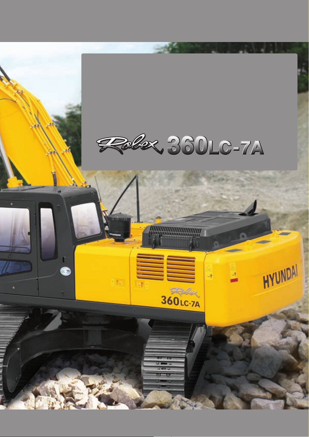
Robex 360LC-7A
Page 3
Built for Maximum Power,
Performance and Reliability.
A new chapter in construction equipment has now begun.
Making the dream a reality.
HYUNDAI CONSTRUCTION EQUIPMENT
02 / 03
Page 4
Robex 360LC-7A
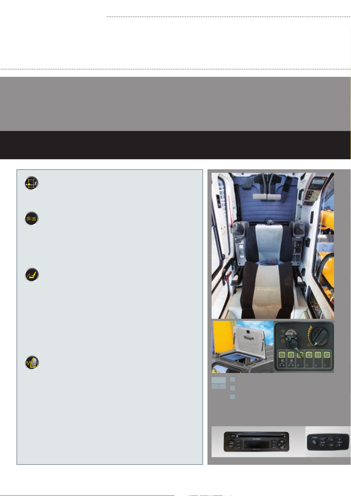
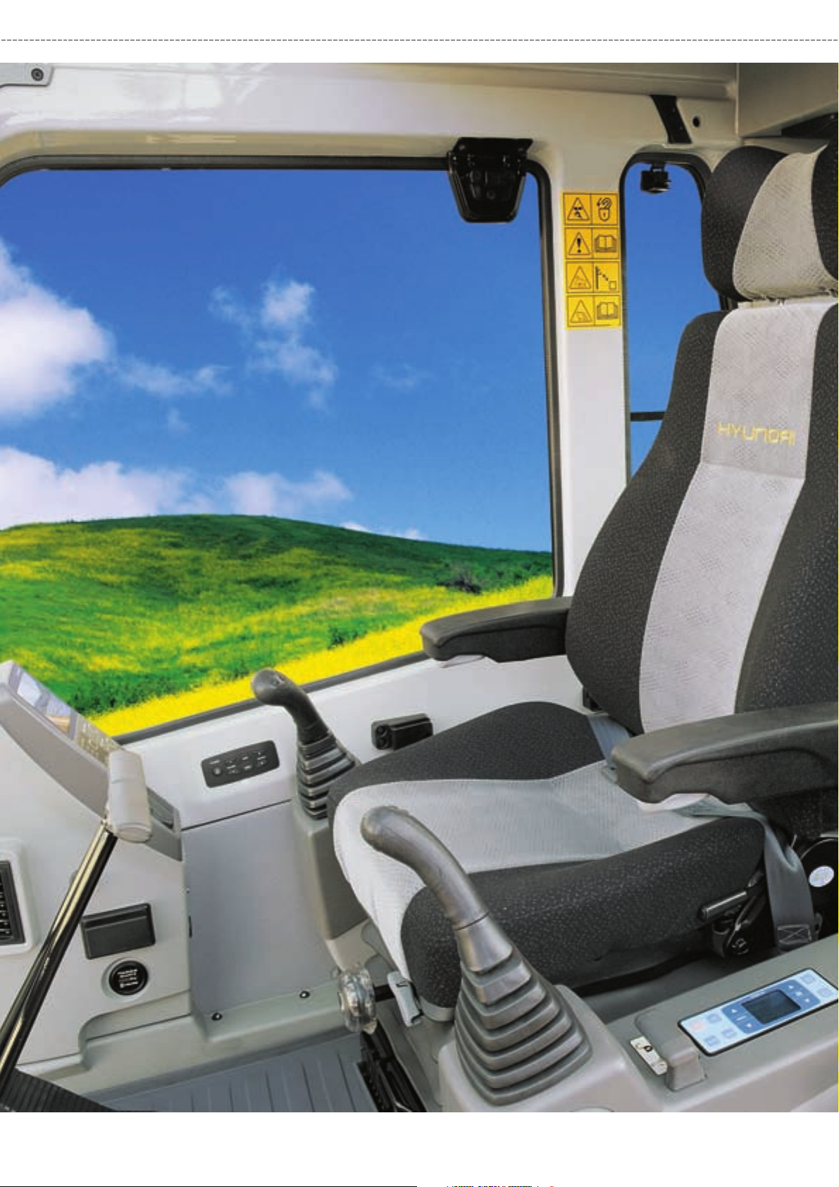
Operator’s Comfort is Our Main Concern.
Wide Cab Exceeds Industry Standards.
Technology in Cab Design
Visibility
.
Even more visibility than before, for safer, more efficient operation.
Excellent Ventilation
.
Ventilation has been improved by the addition of a larger fresh air intake
system and by providing additional air flow throughout the cab.
.
Sliding front and side windows provide improved ventilation.
.
A large sunroof offers upward visibility and additional ventilation.
Comfortable Operator Environment
.
The control levers and seat can be adjusted to provide maximum
operator comfort.
.
The seat is fully adjustable for optimum operating position, reducing
operator fatigue.
.
Console boxes slide forward and backward for improved accessibility.
.
The proportional pressure controls reduce unnecessary exertion while
ensuring precise operation.
.
Large windows allow excellent visibility in all directions.
Low noise design
.
The Robex 7A series is designed with low operation noise in mind.
.
Hyundai engineering made efforts to keep interior and exterior noise levels
to a minimum.
.
The cab's noise levels have been additionally reduced by improving the
door seals for the cab and engine compartments.
.
An insulated diesel engine compartment with sound-damping material
also reduces noise.
1
1
2
Wide, Comfortable Operating Space
3
2
Steel Cover Sunroof
3
Dial Type Engine Speed Switch and / Key Switch
Radio CD Control
Page 5
HYUNDAI CONSTRUCTION EQUIPMENT
04 / 05
Page 6
Robex 360LC-7A
Improved Intelligent Display
Instrument Panel is installed in front of RH
console box. It is easy to check all critical
systems with easy-to-read indicators.
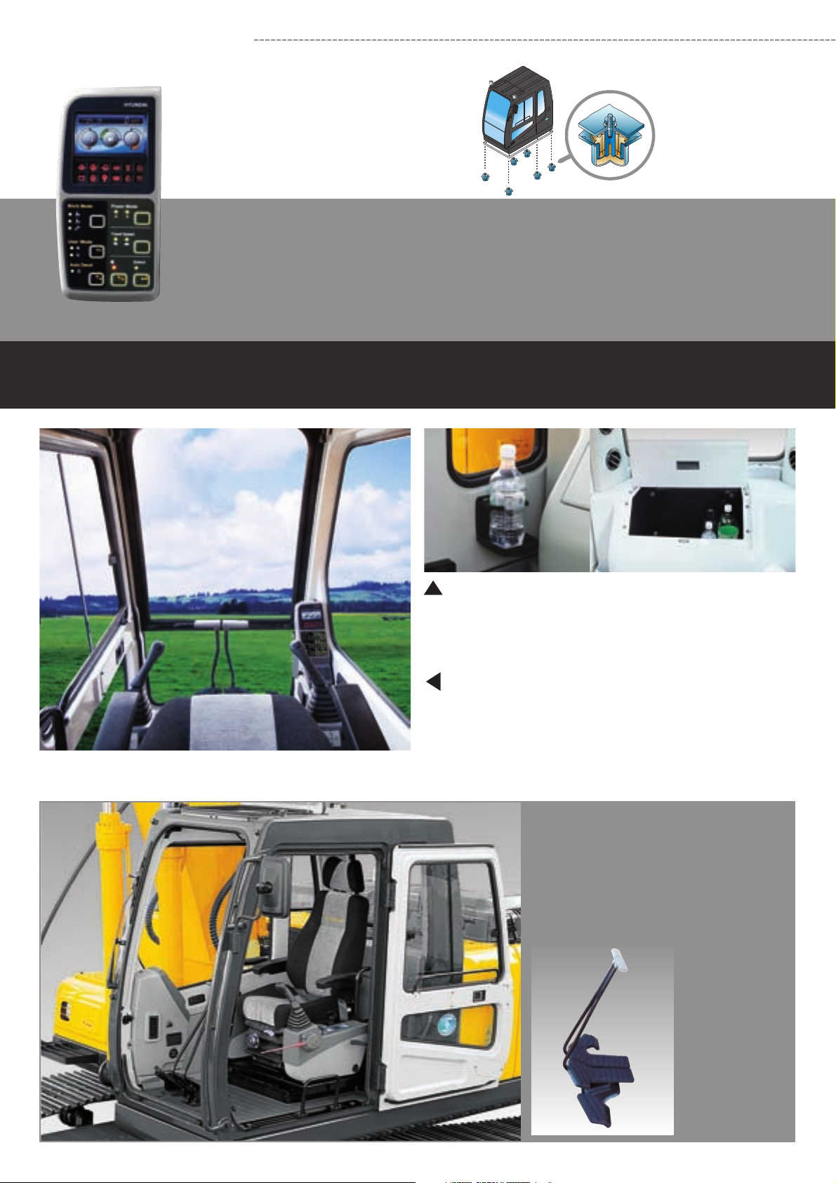
Operating Environment
Minimization of Shock and Vibration through a
Cab Mounting System
The application of the Viscous Mounting system to the cabin
support provides the operator with a smoother ride. The operator
work efficiency will increase as the shock and noise level in the
cabin decreases.
Storage box and Cup Holder
An additional storage box and cup holder are located behind
operator’s seats so to food and beverages cool or hot.
Wide Cab with Excellent Visibility
The cab is roomy and ergonomically designed with low noise level
and a good visibility. A full view front window and large rear and side
windows provide excellent visibility in all directions.
Wide, Comfortable Operating Space
All the controls are designed and positioned
according to the latest ergonomic research.
Reinforced pillars have also been added
forgreater cab rigidity.
Smooth Travel Pedal and Foot Rests
Page 7

Maximum Protection
Highly Sensitive Joystick
and Easy Entrance
New joystick grips for precise
control have been equipped with
double switches.
•
Power boost
•
Left
Right
One touch deceleration
•
Optional (2)
•
Horn
•
Optional (3)
Easy-to-Reach Control
Panels
Switches and other essential
controls are located near the
operator. This helps to keep
operator movements to a
minimum, enhancing control
with less operator’s fatigue.
The better working conditions in a pleasant environment
B
A
C
B
CA
Rear Emergency Exit
Window
Rear Exit Window is designed
to provide an easy exit in
emergency cases.
쐅
쐈
쐉
씈
씉
Raise-up Wiper and Cabin
Lights
Raise-up wiper installed to
enhance a better front view.
Cabin Lights enhances safety by
brightly lighting the surroundings
in dark environments. (optional)
Centralized control panel
Horn button
Option button
Remote Radio control
Travel lever
Cluster
One touch decel button
Hour meter
Travel pedal
Fully adjustable suspension seat
Safety lever
Power boost button
Joystick control lever
Air Conditioner and Heater controller
HYUNDAI CONSTRUCTION EQUIPMENT
06 / 07
Page 8

Automatic Engine
Overheat Prevention
If the engine coolant temperature
gets too high, the CPU controller
lowers the engine speed and cools
the engine.
Anti Restart System
The new system protects the
starter from re-starting during
engine operation, even if the
operator accidentally turns the
start key again.
Power boost control
System
When the power boost system is
activated, digging power increases
about 10%. It is especially useful
when extra power is temporarily
needed, for instance, when digging
hard earth and rock.
Advanced Hydraulic System
Automatic Warming-up
System
After the engine is started, if the
engine coolant temperature is low,
the CPU controller increases the
engine speed and automatically
increases the pump flow rate so to
warm up the engine more
effectively.
ADVANCED CAPO SYSTEM
NEW MODE CONTROL SYSTEM
1
POWER MODE
1
H mode: High power
S mode: Standard power
WORK MODE
2
Heavy duty work
General work
Breaker
2
3
The advanced CAPO (Computer
Aided Power Optimization)
system maintains engine and
mutual pump power at optimum
levels. Mode selections are
designed for various work
loads, maintaining high
performance while reducing
fuel consumption. Features
such as auto deceleration and
power boost are included in the
system. The system monitors
engine speed, coolant
temperature, and hydraulic oil
temperature. Contained within
the system are self diagnostic
capabilities which are
displayed by error codes on the
cluster.
Auto Deceleration System
When remote-control
valves are in neutral
position more than
4 seconds, the CPU
controller instructs
the accelerator
actuator to reduce
engine speed to
1000 rpm. This decreases fuel consumption and
reduces cab noise levels.
Max. Flow Cut-off System
For precise control and finishing work, the Max.
Flow Cut-off System reduces pump flow, thus
allowing smooth operation.
Self Diagnosis System
The CPU controller diagnoses problems in the
CAPO system caused by electric and hydraulic
malfunctions and displays them on the LCD
monitor of the cluster through error codes. This
controller has the capacity to identify 48 distinct
types of errors. The information from this device,
such as engine rpm, main pump delivery
pressure, battery voltage, hyd. temperature, and
the state of all types of electric switches,
provides the operator with an exact condition of
the machine. This instrument makes it easier to
troubleshoot the machine in case of failure.
One Touch Deceleration System
When the one touch deceleration switch is
pressed, the CPU controller controls the
accelerator actuator to reduce engine speed to
800 rpm. Once this switch is pressed again, the
engine speed recovers to its preset RPM.
Pump Flow Control System
In neutral position: Pump flow is reduced to a
minimum to eliminate power loss.
In operation: Maximum pump flow is delivered to
the actuator to increase the speed. With
movement of the control lever, pump flow is
automatically adjusted and the actuator speed
can be proportionally controlled.
Boom & Arm Holding System
The Holding valves in the main control valve
prevents the boom & arm from dropping over an
extended period in neutral position.
Arm Flow Regeneration System
Arm flow regeneration valve provides smooth
arm-in operation without cylinder cavitation.
Hydraulic Damper in Travel Pedal
Improved travel controllability & feeling during
movement of the machine by use of shock
reducing material.
3
USER MODE
M mode: Maximum Power
U mode: Memorizing Operator’s Preferable Power Setting
Page 9

CUMMINS
QSL Engine
The six cylinders,
turbocharged,
4 cycle, charger air cooled
engine is built for power,
reliability, economy and low
emission. This engine
meets Tier III
emissions regulation.
Heavy-duty strength
Everyone who’s ever worked on construction
equipment machines knows, there is no
substitute for power and durabilty. The QSL
handles the toughest loads and the roughest
working conditions. At the same time, it delivers
better fuel economy, has better cold starting
capability and is up to 50% quieter in operation.
The heavy-duty design of the QSL engine block
and components such as articulated pistons,
enhanced camshaft and roller cam followers,
viscous damper and high capacity lube system
add reliability and durability you can count on
every day, year after year. Both fuel-efficiency
and response are significantly enhanced with the
Cummins high pressure common rail fuel system.
The system delivers a continuous high pressure
injection independent of engine speed for
optimum performance and flexibility at every rpm.
Increased Higher Performance
Strong and Stable Lower Frame
Reinforced box-section frame is all welded using low-stress, high-strength steel. It guarantees safety
and resistance against external impact when driving on rough ground or working on wet sites. The
use of highly durable upper and lower rollers and track guards ensures proper machine transfer on all
terrains. The long undercarriage incorporates heavy duty excavator style components. An X-leg type
center frame is integrally welded for maximum strength and durability.
Reinforced Bucket and Bucket Linkage
To prevent excessive wear of pins and bushes,
sealed joints have been applied. Bucket link
design incorporates high durability and anti wear
characteristics. Additional reinforcement plates
on cutting edge section are welded. Thicker
steel and an additional lateral plate are put in
place to reinforce the bucket.
Powerful and Precise Swing Control
Improved shock absorbing characteristics make
stopping swing movement a precise and smooth
action.
Track Rail Guide & Adjusters
Durable track rail guides keep track links in place. Track adjustment is made easy by using a standard
grease operated cylinder track adjusters including shock absorbing springs. (Full Track Guide: Option)
HYUNDAI CONSTRUCTION EQUIPMENT
08 / 09
Page 10

Robex 360LC-7A
Full open doors and the use of one master key system
provide easy access during servicing.
Reliability & Serviceability
Side Cover with Left & Right Swing Open Type
Easy access to vital components gives unrestricted view of
components allowing easy maintenance and repair.
Centralized Electric Control Box
and Easy Change Air Cleaner
Assembly
Electric control box and air cleaner are
centralized in one and the same
compartment for easy service.
Highly efficient Hydraulic Pump
Pump output capacity has been increased.
Easy to maintain engine components
A cooling and preheating system are provided for optimum and
immediate operation, guaranteeing longer life for the engine and
hydraulic components.
Servicing of the engine and hydraulics is considerably simplified
due to total accessibility.
Large tool box for extra storage
Page 11

Durability of structure
proven through FEM
(Finite Element Method)
analysis and long term
durability test.
HYUNDAI CONSTRUCTION EQUIPMENT
10 / 11
Page 12

Specifications
Engine
Model
Water cooled, 4 cycle Diesel, 6-Cylinders
in line, direct injection, turbocharged,
charged air cooled and low emission
221 kW (296 HP) at 1,850 rpm
202 kW (271 HP) at 1,850 rpm
221 kW (300 PS) at 1,850 rpm
202 kW (275 PS) at 1,850 rpm
1,383 Nm (1,000 lbf.ft) at 1,400 rpm
114 x 144.5 mm (4.5” x 5.3”)
8,900 cc (540 cu in)
2 x 12 V x 160 AH
24 V - 7.5 kW
24 V - 50 Amp
Rated
flywheel
horse
power
Type
J1995 (gross)
SAE
J1349 (net)
6271/1 (gross)
DIN
6271/1 (net)
Max. torque
Bore x stroke
Piston
Batteries
Starting motor
Alternator
Hydraulic system
Main pump
Type
Max. flow
Sub-pump for pilot circuit
Cross-sensing and fuel saving pump system
Hydraulic motors
Travel
Swing
Relief valve setting
Implement circuits
Travel
Power boost (boom, arm, bucket)
Swing circuit
Pilot circuit
Service valve
Hydraulic cylinders
No. of cylinder bore x rod x stroke
Boom: 2-160 x 110 x 1,500 mm (6.3” x 4.2” x 59.1”)
Arm: 1-170 x 120 x 1,760 mm (6.7” x 4.7” x 69.3”)
Bucket: 1-150 x 105 x 1,295 mm (5.9” x 4.1” x 51.0”)
Two variable displacement piston pumps
2x288
Gear pump
Two speed axial piston motor with brake
valve and parking brake
Axial piston motor with automatic brake
32,4 MPa (4,690 psi)
32,8 MPa (4,765 psi)
35,3 MPa (5,120 psi)
25,5 MPa (3,700 psi)
3,4 MPa (500 psi)
Installed
Cummins QSL
/min (76.6 US gpm / 63.8 UK gpm)
l
Swing System
Swing motor
Swing reduction
Swing circuit lubrication
Swing brake
Swing speed
Axial piston motor
Planetary gear reduction
Grease-bathed
Multi wet disc
9.0 rpm
Coolant & Lubricant Capacity
(refilling)
Fuel tank
Engine coolant
Engine oil
Swing device
Final drive (each)
Hydraulic system
Hydraulic tank
liter US gal UK gal
520
45.0
31.7
8.0
7.0
380
230
137.4
11.9
8.4
1.6
1.8
100.4
60.8
114.4
9.9
7.0
1.3
1.5
83.6
50.6
Undercarriage
X-leg type centre frame is integrally welded with reinforced box-section track
frames. The undercarriage includes lubricate rollers, idlers, track adjusters with
shock absorbing spring and sprockets. Track chains with double or triple
grouser shoes.
Centre frame
Track frame
No. of shoes on each side
No. of carrier roller on each side
No. of track roller on each side
No. of track guard on each side
X - leg type
Pentagonal box type
51
2
9
2
Operating Weight (approximate)
Operating weight, including 6,500 m (21’ 4”) boom; 3,200 m (10’ 6”) arm,
SAE heaped 1.62 m
3
(2.12 yd3) backhoe bucket, lubricant, coolant.
Drives & Brakes
Drive method
Drive motor
Reduction system
Max. drawbar pull
Max. travel speed (high) / (low)
Gradeability
Parking brake
Fully hydrostatic type
Axial piston motor, in-shoe design
Planetary reduction gear
310 kN (68,350 lbf)
4.8 km/hr (2.8 mph) / 3.0 km/hr (2.0 mph)
35° (70 %)
Multi wet disc
Control
Pilot pressure operated joysticks and pedals with detachable lever provide almost
effortless and fatigueless operation.
Pilot control
Traveling and steering
Engine throttle
External Lights
Two joysticks with one safety lever
(LH): Swing and arm,
(RH): Boom and bucket (ISO)
Two levers with pedals
Electric, Dial type
Two lights mounted on the boom
one under the battery box
Major component weight
Upper structure
Counterweight
Boom (with arm cylinder)
Operating weight
Shoes (Triple grouser)
mm (in)
600 (24)
700 (28)
750 (30)
800 (32)
900 (36)
Standard equipment
8,500 kg (18,740 lb)
6,500 kg (14,330 lb)
3,780 kg (8,330 lb)
Operating weight
kg (lb)
36,100 (79,590)
36,500 (80,600)
36,725 (81,000)
36,950 (81,500)
37,400 (82,500)
Ground pressure
MPa (psi)
0.063 (9.10)
0.055 (7.96)
0.051 (7.39)
0.048 (6.97)
0.043 (6.26)
Page 13

Backhoe attachment
Buckets
SAE heaped
3
m
(yd3)
1.15 (1.50)
1.46 (1.91)
1.62 (2.12)
1.86 (2.43)
2.10 (2.75)
2.32 (3.03)
1.62 (2.12)
1.44 (1.88)
1.62 (2.12)
1.86 (2.43)
Capacity m3(yd3) Width mm (in)
SAE heaped CECE heaped
1.15 (1.50)
1.46 (1.91)
1.62 (2.12)
1.86 (2.43)
2.10 (2.75)
2.32 (3.03)
1.62 (2.12)
1.44 (1.88)
1.62 (2.12)
1.86 (2.43)
: Standard backhoe bucket
: Heavy-duty
: Rock bucket-Heavy duty
1.00 (1.31)
1.27 (1.66)
1.40 (1.83)
1.60 (2.1)
1.80 (2.4)
2.00 (2.62)
1.40 (1.83)
1.27 (1.66)
1.40 (1.83)
1.60 (2.1)
Without side
cutters
1,090 (42.9)
1,380 (54.3)
1,440 (56.7)
1,620 (63.8)
1,810 (71.3)
1,990 (78.3)
1,540 (60.6)
1,280 (50.4)
1,545 (60.8)
1,725 (67.9)
With
side cutters
1,220 (48.0)
1,510 (59.4)
1,570 (61.8)
1,750 (68.9)
1,940 (76.4)
2,120 (83.5)
-
-
-
-
Weight
kg (lb)
1,030 (2,270)
1,170 (2,580)
1,280 (2,820)
1,390 (3,060)
1,520 (3,350)
1,760 (3,880)
1,570 (3,460)
1,565 (3,450)
1,610 (3,550)
1,710 (3,770)
Boom
2,500
Arm
(8’ 2”)
: Applicable for materials with density of 2,000 kg/m3(3,370 lb/yd3) or less
: Applicable for materials with density of 1,600 kg/m
: Applicable for materials with density of 1,100 kg/m
Recommendation mm (ft.in)
6,500 (21’ 4”)
3,200
(10’ 6”)
3,900
(12’ 10”)
-
4,300
(14’ 1”)
-
-
-
6,150 (20’ 2”) 8,600 (28’ 3”)
2,500
(8’ 2”)
5,100
(16’ 9”)
-
-
-
-
-
-
-
-
3
(2,700 lb/yd3) or less
3
(1,850 lb/yd3) or less
Backhoe attachment
Boom and arms are of all-welded, low-stress, full-box section design. 6,500 mm (21’ 4”); 6,150 mm (20’2”); 8,600 mm (28’3”) boom and 2,500 mm (8’ 2”); 3,200 mm (6’ 7”);
3,900 mm (12’ 10”); 4,300 mm (14’1”); 5,100 mm (16’9”) arms are available. Buckets are all-welded, high-strength steel implements.
2,500 mm (8’ 2”)
3,200 mm (10’ 6”)
Digging force
SAE
ISO
SAE
ISO
mm (ft.in)
kg (lb)
kN
kgf
lbf
kN
kgf
lbf
kN
kgf
lbf
kN
kgf
lbf
2,500 (8’ 2”)
1,930 (4,260)
201.0 [219.3]
20500 [22360]
45190 [49300]
228.5 [249.3]
23300 [25420]
51370 [56040]
184.4 [201.1]
18800 [20510]
41450 [45220]
192.2 [209.7]
19600 [21380]
43210 [47140]
3,200 (10’ 6”)
1,960 (4,320)
201.0 [219.3]
20500 [22360]
45190 [49300]
228.5 [249.3]
23300 [25420]
51370 [56040]
152.0 [165.8]
15500 [16910]
34170 [37280]
156.9 [171.2]
16000 [17450]
35270 [38480]
3,900 (12’ 10”)
2,170 (4,780)
201.0 [219.3]
20500 [22360]
45190 [49300]
228.5 [249.3]
23300 [25420]
51370 [56040]
135.3 [147.6]
13800 [15050]
30420 [33190]
139.3 [151.9]
14200 [15490]
31310 [34160]
Arm
Length
Weight
Bucket
digging
force
Arm
crowd
force
Note: Arm weight including bucket cylinder and linkage. Standard arm
3,900 mm (12’ 10”)
4,300 mm (14’ 1”)
5,100 mm (16’ 9”)
4,300 (14’ 1”)
Remark
2,290 (5,050)
201.0 [219.3]
20500 [22360]
45190 [49300]
228.5 [249.3]
23300 [25420]
51370 [56040]
124.5 [135.9]
Power Boost
12700 [13850]
28000 [30550]
128.5 [140.1]
13100 [14290]
28880 [31510]
HYUNDAI CONSTRUCTION EQUIPMENT
[ ]:
12 / 13
Page 14

360LC-7A
Dimensions & Working ranges
Dimensions
Tumbler distance
A
Overall length of crawler
B
C
Ground clearance of counterweight
D
Tail swing radius
D’
Rear-end length
E
Overall width of upper structure
F
Overall height of cab
G
Min. ground clearance
Track gauge
H
Working ranges
(meters)
(feet)
40
12
11
35
10
30
9
8
25
7
20
D
B
6
5
15
4
E
10
3
2
5
1
0
0
1
5
2
3
10
C
B’
4
15
5
6
20
7
25
8
9
30
131211109876543210
4040 35 30 25 20 15 10 5 0
mm (ft in)
4,340 (14 ’3”)
5,280 (17’ 4”)
1,290 (4’ 3”)
3,415 (11’ 2”)
3,350 (11’ 0”)
2,980 (9’ 9”)
3,175 (10’ 5”)
550 (1’ 10”)
2,740 (9’ 0”)
A
A’
F
360LC-7A
(meters)
(feet)
Boom length
Arm length
Overall length
I
Overall height of
J
boom
Track shoe width
K
Overall width
L
Standard Equipment
Boom length
Arm length
Max. digging reach
A
Max. digging reach
A’
on ground
Max. digging depth
B
Max. digging depth
B’
(8' level)
Max. vertical wall
C
digging depth
Max. digging
D
height
Max. dumping
E
height
Min. swing radius
F
Standard Equipment
2,500
(8’ 2”)
11,240
(36’ 11”)
3,700
(12’ 2”)
600
(24”)
3,340
(10’ 11”)
2,500
(8’ 2”)
10,720
(35’ 2”)
10,490
(34’ 5”)
6,800
(22’ 4”)
6,620
(21’ 9”)
5,940
(19’ 6”)
10,470
(34’ 4”)
7,270
(23’ 10”)
4,630
(14’ 2”)
6,500 (21’ 4”)
3,200
(10’ 6”)
11,120
(36’ 6”)
3,440
(11’ 3”)
700
(28”)
3,440
(11’ 3”)
6,500 (21’ 4”)
3,200
(10’ 6”)
11,250
(36’ 11”)
11,000
(36’ 1”)
7,500
(24’ 7”)
7,350
(24’ 1”)
6,340
(20’ 10”)
10,430
(34’ 3”)
7,290
(23’ 11”)
4,560
(14’ 12”)
3,900
(12’ 10”)
11,070
(36’ 4”)
3,870
(12’ 8”)
750
(30”)
3,490
(11’ 5”)
3,900
(12’ 10”)
11,870
(38’ 11”)
11,670
(38’ 3”)
8,200
(26’ 11”)
8,070
(26’ 6”)
7,040
(23’ 1”)
10,650
(34’ 11”)
7,510
(24’ 8”)
4,550
(14’ 11”)
6,150 (20’ 2”) 8,600 (28’ 3”)
4,300
(14’ 1”)
11,050
(36’ 3”)
4,270
(14’ 0”)
3,540
(11’ 7”)
6,150 (20’ 2”) 8,600 (28’ 3”)
4,300
(14’ 1”)
12,380
(39’ 12”)
12,180
(40’ 0”)
8,600
(28’ 3”)
8,480
(27’ 10”)
7,550
(24’ 9”)
11,210
(36’ 9”)
8,030
(26’ 4”)
4,570
(14’ 12”)
2,500
(8’ 2”)
10,880
(35’ 8”)
3,830
(12’ 7”)
800
(32”)
2,500
(8’ 2”)
10,330
(33’ 11”)
10,100
(33’ 2”)
6,440
(21’ 2”)
6,260
(20’ 6”)
5,500
(18’ 1”)
10,200
(33’ 6”)
7,020
(23’ 0”)
4,320
(14’ 2”)
mm (ft in)
5,100
(16’ 9”)
13,070
(42’ 11”)
4,830
(15’ 10”)
900
(36”)
3,640
(11’ 11”)
mm (ft in)
5,100
(16’ 9”)
15,300
(50’ 2”)
15,120
(49’ 7”)
11,210
(36’ 9”)
11,100
(36’ 5”)
10,070
(33’ 0”)
13,160
(43’ 2”)
9,990
(32’ 9”)
6,040
(19’ 10”)
Page 15

Lifting Capacities
Lifting capacities
BBoooomm::
•
6.15 m (20’ 2”) •
Load point
height
m (ft)
9.0 m
30.0 ft
7.5 m
25.0 ft
6.0 m
20.0 ft
4.5 m
15.0 ft
3.0 m
10.0 ft
1.5 m
5.0 ft
Ground Line
-1.5 m
-5.0 ft
-3.0 m
-10.0 ft
-4.5 m
-15.0 ft
BBoooomm::
•
6.5 m (21’ 4”) •
Load point
height
m (ft)
9.0 m
30.0 ft
7.5 m
25.0 ft
6.0 m
20.0 ft
4.5 m
15.0 ft
3.0 m
10.0 ft
1.5 m
5.0 ft
Ground Line
-1.5 m
-5.0 ft
-3.0 m
-10.0 ft
-4.5 m
-15.0 ft
AArrmm::
kg
lb
kg
lb
kg
lb
kg
lb
kg
lb
kg
lb
kg
lb
kg
lb
kg
lb
kg
lb
AArrmm::
kg
lb
kg
lb
kg
lb
kg
lb
kg
lb
kg
lb
kg
lb
kg
lb
kg
lb
kg
lb
2.5 m (8’ 2”) •
3.0 m(10.0 ft)
*18380
*40520
*13370
*29480
*20990
*46270
*23670
*52180
*18590
*40980
2.5 m (8’ 2”) •
3.0 m(10.0 ft)
*17800
*39240
*23550
*51920
*19520
*43030
*18380
*40520
*13370
*29480
*20990
*46270
*23670
*52180
*18590
*40980
*17800
*39240
*23550
*51920
*19520
*43030
BBuucckkeett::
1.62 m3(2.12 yd3) SAE heaped •
4.5 m(15.0 ft) 6.0 m(20.0 ft) 7.5 m(25.0 ft)
*12260
*27030
*15570
*34330
*18030
*39750
*18930
*41730
*18580
*40960
*17040
*37570
*13590
*29960
BBuucckkeett::
1.62 m3(2.12 yd3) SAE heaped •
4.5 m(15.0 ft) 6.0 m(20.0 ft) 7.5 m(25.0 ft)
*11980
*26410
*15410
*33970
*17780
*39200
*18570
*40940
*18280
*40300
*17040
*37570
*14370
*31680
Rating over-front Rating over-side or 360 degree
SShhooee::
600 mm (24”) triple grouser with 6,500 kg (14,330 lb) CW
Load radius At max. reach
Capacity
*7640
*16840
*7520
*16580
*7580
*16710
7200
15870
6790
14970
6750
14880
7090
15630
7990
17610
*8470
*18670
*12260
*27030
13710
30230
12630
27840
12120
26720
11990
26430
12100
26680
12520
27600
*8660
*19090
*9890
*21800
*11460
*25260
*12850
*28330
*13670
*30140
*13710
*30230
*12670
*27930
SShhooee::
*8660
*19090
9350
20610
8720
19220
8150
17970
7770
17130
7610
16780
7650
16870
600 mm (24”) triple grouser with 6,500 kg (14,330 lb) CW
*6540
*14420
*8740
*19270
*9500
*20940
10010
22070
9760
21520
9650
21270
6530
14400
6330
13960
6030
13290
5730
12630
5500
12130
5410
11930
Load radius At max. reach
Capacity
*6900
*15210
*6870
*15150
*6970
*15370
6550
14440
6210
13690
6180
13620
6490
14310
7260
16010
*8130
*17920
*7460
*16450
*11980
*26410
12960
28570
12000
26460
11650
25680
11630
25640
11830
26080
12280
27070
*8050
*17750
*9400
*20720
*11030
*24320
*12460
*27470
*13320
*29370
*13480
*29720
*12770
*28150
*8050
*17750
8990
19820
8330
18360
7780
17150
7450
16420
7340
16180
7430
16380
*7580
*16710
*8180
*18030
*9020
*19890
9750
21500
9520
20990
9440
20810
6370
14040
6110
13470
5790
12760
5490
12100
5280
11640
5210
11490
*7640
*16840
5970
13160
4800
10580
4190
9240
3890
8580
3830
8440
4010
8840
4540
10010
5730
12630
*6900
*15210
5190
11440
4240
9350
3720
8200
3470
7650
3430
7560
3610
7960
4070
8970
5070
11180
*7460
*16450
Reach
m
(ft)
6.65
(21.8)
8.02
(26.3)
8.88
(29.1)
9.38
(30.8)
9.58
(31.4)
9.52
(31.2)
9.19
(30.2)
8.53
(28.0)
7.47
(24.5)
Reach
m
(ft)
7.22
(23.7)
8.49
(27.9)
9.29
(30.5)
9.77
(32.1)
9.97
(32.7)
9.91
(32.5)
9.59
(31.5)
8.97
(29.4)
7.97
(26.1)
6.39
(21.0)
BBoooomm::
•
NOTES
Ground Line
6.5 m (21’ 4”) •
Load point
height
AArrmm::
3.2 m (10’ 6”) •
1.5 m(5.0 ft)
BBuucckkeett::
1.62 m3(2.12 yd3) SAE heaped •
3.0 m(10.0 ft) 4.5 m(15.0 ft) 6.0 m(20.0 ft) 7.5 m(25.0 ft) 9.0m(30.0 ft)
m (ft)
9.0 m
30.0 ft
7.5 m
25.0 ft
6.0 m
20.0 ft
4.5 m
15.0 ft
3.0 m
10.0 ft
1.5 m
5.0 ft
-1.5 m
-5.0 ft
-3.0 m
-10.0 ft
-4.5 m
-15.0 ft
-6.0 m
-20.0 ft
1. Lifting capacity is based on SAE J1097, ISO 10567.
2. Lifting capacity of the Robex Series does not exceed 75% of tipping load with the
kg
lb
kg
lb
kg
lb
kg
lb
kg
lb
kg
lb
kg
lb
kg
lb
kg
lb
kg
lb
kg
lb
machine on firm, level ground or 87% of full hydraulic capacity.
*13680
*30160
*17850
*39350
*22570
*49760
*13680
*30160
*17850
*39350
*22570
*49760
*13060
*28790
*17490
*38560
*22770
*50200
*22590
*49800
*13060
*28790
*17490
*38560
*22770
*50200
*22590
*49800
*13690
*30180
*16650
*36710
*18210
*40150
*18550
*40900
*17870
*39400
*16000
*35270
*11900
*26230
SShhooee::
600 mm (24”) triple grouser with 6,500 kg (14,330 lb) CW
Load radius At max. reach
Capacity
*6020
*6020
*13270
*13270
4440
9790
4260
9390
4080
8990
3930
8660
*6110
*13470
*6140
*13540
6020
13270
5710
12590
5670
12500
5900
13010
6480
14290
7700
16980
*8000
*17640
10250
13180
*10120
*6710
*14790
*7420
*8350
*8350
*18410
*10100
13640
*22270
30070
*11760
12420
*25930
27380
*12930
11800
*28510
26010
*13460
11600
*29670
25570
*13210
11660
*29120
25710
*11870
11960
*26170
26370
*11900
*26230
3. The load point is a hook (standard equipment) located on the back of the bucket.
4. (*) indicates load limited by hydraulic capacity.
*18410
8600
18960
7980
17590
7540
16620
7330
16160
7310
16120
7510
16560
*16360
*8370
*18450
*9330
*20570
21080
20720
20720
9560
9400
9400
6590
14530
6290
13870
5930
13070
5590
12320
5320
11730
5170
11400
5180
11420
*4490
*9900
*6400
*14110
7260
16010
7100
15650
*4590
*4590
*10120
HYUNDAI CONSTRUCTION EQUIPMENT
4650
3860
8510
3410
7520
3180
7010
3120
6880
3240
7140
3590
7910
4320
9520
5980
Reach
m
(ft)
7.97
(26.1)
9.12
(29.9)
9.87
(32.4)
10.32
(33.9)
10.5
(34.4)
10.45
(34.3)
10.14
(33.3)
9.57
(31.4)
8.65
(28.4)
7.25
(23.8)
14 / 15
Page 16

Lifting Capacities
Lifting capacities
BBoooomm::
•
6.5 m (21’ 4”) •
Load point
height
m (ft)
9.0 m
30.0 ft
7.5 m
25.0 ft
6.0 m
20.0 ft
4.5 m
15.0 ft
3.0 m
10.0 ft
1.5 m
5.0 ft
Ground Line
-1.5 m
-5.0 ft
-3.0 m
-10.0 ft
-4.5 m
-15.0 ft
-6.0 m
-20.0 ft
BBoooomm::
•
6.5 m (21’ 4”) •
Load point
height
m (ft)
9.0 m
30.0 ft
7.5 m
25.0 ft
6.0 m
20.0 ft
4.5 m
15.0 ft
3.0 m
10.0 ft
1.5 m
5.0 ft
Ground Line
-1.5 m
-5.0 ft
-3.0 m
-10.0 ft
-4.5 m
-15.0 ft
-6.0 m
-20.0 ft
AArrmm::
kg
lb
kg
lb
kg
lb
kg
lb
kg
lb
kg
lb
kg
lb
kg
*12590
lb
*27760
kg
*16200
lb
*35710
kg
*20270
lb
*44690
kg
lb
AArrmm::
kg
lb
kg
lb
kg
lb
kg
lb
kg
lb
kg
lb
kg
lb
kg
*11080
lb
*24430
kg
*14380
lb
*31700
kg
*18170
lb
*40060
kg
*22830
lb
*50330
3.9 m (12’ 10”) •
1.5 m(5.0 ft)
*12590
*27760
*16200
*35710
*20270
*44690
4.3 m (14’ 1”) •
*17000
*37480
*13680
*30160
*13030
*28730
*15420
*11080
*34000
*24430
*19060
*14380
*42020
*31700
*24050
*18170
*53020
*40060
*21250
*22830
*46850
*50330
Rating over-front Rating over-side or 360 degree
BBuucckkeett::
1.62 m3(2.12 yd3) SAE heaped •
SShhooee
: 600 mm (24”) triple grouser with 6,500 kg (14,330 lb) CW
Load radius At max. reach
3.0 m(10.0 ft) 4.5 m(15.0 ft) 6.0 m(20.0 ft) 7.5 m(25.0 ft) 9.0m(30.0 ft)
*3660
*5890
*19900
*43870
*12660
*27910
*13680
*30160
*16830
*37100
*21040
*46390
*24240
*53440
*19460
*42900
BBuucckkeett
: 1.62 m3(2.12 yd3) SAE heaped •
*43870
*12660
*27910
*13680
*30160
*16830
*37100
*21040
*46390
*24240
*53440
*19460
*42900
*26540
*15330
*33800
*17420
*38400
*18250
*40230
*18030
*39750
*16700
*36820
*13690
*30180
*12040
*19900
*12040
*26540
12590
27760
11750
25900
11390
25110
11340
25000
11540
25440
12040
26540
*5890
*12990
*12990
*6660
*14680
*7660
*9120
*20110
*10910
*24050
*12310
*27140
*13100
*28880
*13170
*29030
*12330
*27180
SShhooee
8690
*16890
19160
*8710
7990
*19200
17610
16470
15810
15610
15830
7470
7170
7080
7180
9470
20880
9240
20370
9170
20220
*9270
*20440
: 600 mm (24”) triple grouser with 6,500 kg (14,330 lb) CW
6330
13960
5930
13070
5540
12210
5220
11510
5020
11070
4960
10930
5080
11200
*8070
*5450
*12020
*6860
*15120
7200
15870
6990
15410
6870
15150
Load radius At max. reach
*17000
*37480
*13680
*30160
*13030
*28730
*15420
*34000
*19060
*42020
*24050
*53020
*21250
*46850
4.5 m(15.0 ft)3.0 m(10.0 ft)1.5 m(5.0 ft)
*10840
*23900
*14340
*31610
*16790
*37020
*17980
*39640
*18090
*39880
*17140
*37790
*14730
*32470
6.0 m(20.0 ft) 7.5 m(25.0 ft) 9.0m(30.0 ft) 10.5m(35.0 ft)
*2740
*6040
*4460
*9830
*5620
*6110
*10840
*23900
12850
28330
11840
26100
11350
25020
11210
24710
11340
25000
11750
25900
*8410
*18540
*10300
*22710
*11850
*26120
*12820
*28260
*13120
*28920
*12590
*27760
*10720
*23630
*8410
*18540
8090
17840
7500
16530
7140
15740
6990
15410
7040
15520
7330
16160
*6110
*13470
*7160
*15790
*8270
*18230
*9250
*20390
9210
20300
9090
20040
9150
20170
*13470
6000
13230
5580
12300
5220
11510
4980
10980
4870
10740
4930
10870
*12390
*6460
*14240
*7120
*15700
6970
15370
6810
15010
*6650
*14660
*2740
*6040
*4460
*9830
4490
9900
4250
9370
4000
8820
3790
8360
3650
8050
3610
7960
*2660
*5860
*2990
*6590
*3660
*8070
4440
9790
4230
9330
4000
8820
3820
8420
3710
8180
*2660
*5860
2920
6440
*5290
*11660
*5420
*11950
*5590
*12320
5380
11860
5120
11290
5060
11160
5230
11530
5670
12500
6560
14460
*7640
*16840
*11130
*10600
*10360
*10430
*15370
*15060
Capacity
Capacity
*5050
*4810
*4700
*4730
4680
10320
4630
10210
4770
10520
5140
11330
5870
12940
*6970
*6830
5130
11310
4000
8820
3360
7410
2980
6570
2780
6130
2720
6000
2800
6170
3060
6750
3600
7940
4710
10380
13320
4420
9740
3510
7740
2980
6570
2650
5840
2480
5470
2430
5360
2500
5510
2710
5970
3160
6970
4020
8860
6040
Reach
m
(ft)
8.81
(28.9)
9.85
(32.3)
10.54
(34.6)
10.95
(35.9)
11.13
(36.5)
11.07
(36.3)
10.79
(35.4)
10.26
(33.7)
9.42
(30.9)
8.17
(26.8)
Reach
m
(ft)
9.45
(31.0)
10.42
(34.2)
11.07
(36.3)
11.46
(37.6)
11.63
(38.2)
11.58
(38.0)
11.31
(37.1)
10.81
(35.5)
10.02
(32.9)
8.87
(29.1)
7.15
(23.5)
BBoooomm::
•
NOTES
Ground Line
6.5 m (21’ 4”) •
Load point
height
AArrmm
: 3.2 m (10’ 6”) •
1.5 m(5.0 ft)
BBuucckkeett
: 1.62 m3(2.12 yd3) SAE heaped •
3.0 m(10.0 ft) 4.5 m(15.0 ft) 6.0 m(20.0 ft) 7.5 m(25.0 ft) 9.0m(30.0 ft)
m (ft)
9.0 m
30.0 ft
7.5 m
25.0 ft
6.0 m
20.0 ft
4.5 m
15.0 ft
3.0 m
10.0 ft
1.5 m
5.0 ft
-1.5 m
-5.0 ft
-3.0 m
-10.0 ft
-4.5 m
-15.0 ft
-6.0 m
-20.0 ft
1. Lifting capacity is based on SAE J1097, ISO 10567.
2. Lifting capacity of the Robex Series does not exceed 75% of tipping load with the
kg
lb
kg
lb
kg
lb
kg
lb
kg
lb
kg
lb
kg
lb
kg
lb
kg
lb
kg
lb
kg
lb
machine on firm, level ground or 87% of full hydraulic capacity.
*13680
*30160
*17850
*39350
*22570
*49760
*13680
*30160
*17850
*39350
*22570
*49760
*13060
*28790
*17490
*38560
*22770
*50200
*22590
*49800
*13060
*28790
*17490
*38560
*22770
*50200
*22590
*49800
*13690
*30180
*16650
*36710
*18210
*40150
*18550
*40900
*17870
*39400
*16000
*35270
*11900
*26230
SShhooee
: 800 mm (31.5”) triple grouser with 6,500 kg (14,330 lb) CW
Load radius At max. reach
Capacity
*6020
*6020
*13270
*13270
*4490
*9900
4390
9680
4210
9280
4060
8950
*6110
*13470
*6140
*13540
6200
13670
5890
12990
5850
12900
6080
13400
6680
14730
7930
17480
*8000
*17640
10540
13560
*10120
*14790
*8350
*8350
*18410
*10100
*13690
*22270
*30180
*11760
12750
*25930
28110
*12930
12130
*28510
26740
*13460
11930
*29670
26300
*13210
11990
*29120
26430
*11870
12290
*26170
27090
*11900
*26230
3. The load point is a hook (standard equipment) located on the back of the bucket.
4. (*) indicates load limited by hydraulic capacity.
*18410
8820
19440
8190
18060
7760
17110
7550
16640
7530
16600
7730
17040
*16360
*18450
*20570
*6710
*7420
*8370
*9330
9840
21690
9670
21320
9670
21320
*6710
*14790
6460
14240
6100
13450
5750
12680
5480
12080
5340
11770
5340
11770
*4490
*9900
*6400
*14110
7470
16470
*7120
*15700
*4590
*4590
*10120
4780
3970
8750
3520
7760
3290
7250
3240
7140
3360
7410
3710
8180
4460
9830
6150
Reach
m
(ft)
7.97
(26.1)
9.12
(29.9)
9.87
(32.4)
10.32
(33.9)
10.5
(34.4)
10.45
(34.3)
10.14
(33.3)
9.57
(31.4)
8.65
(28.4)
7.25
(23.8)
Page 17

Lifting capacities
Rating over-front Rating over-side or 360 degree
BBoooomm::
•
BBoooomm::
•
Ground Line
Ground Line
6.5 m (21’ 4”) •
Load point
height
m (ft)
9.0 m
30.0 ft
7.5 m
25.0 ft
6.0 m
20.0 ft
4.5 m
15.0 ft
3.0 m
10.0 ft
1.5 m
5.0 ft
-1.5 m
-5.0 ft
-3.0 m
-10.0 ft
-4.5 m
-15.0 ft
-6.0 m
-20.0 ft
6.5 m (21’ 4”) •
Load point
height
m (ft)
9.0 m
30.0 ft
7.5 m
25.0 ft
6.0 m
20.0 ft
4.5 m
15.0 ft
3.0 m
10.0 ft
1.5 m
5.0 ft
-1.5 m
-5.0 ft
-3.0 m
-10.0 ft
-4.5 m
-15.0 ft
-6.0 m
-20.0 ft
AArrmm::
kg
lb
kg
lb
kg
lb
kg
lb
kg
lb
kg
lb
kg
lb
kg
*12590
lb
*27760
kg
*16200
lb
*35710
kg
*20270
lb
*44690
kg
lb
AArrmm::
kg
lb
kg
lb
kg
lb
kg
lb
kg
lb
kg
lb
kg
lb
kg
*11080
lb
*24430
kg
*14380
lb
*31700
kg
*18170
lb
*40060
kg
*22830
lb
*50330
3.9 m (12’ 10”) •
1.5 m(5.0 ft)
*12590
*27760
*16200
*35710
*20270
*44690
4.3 m (14’ 1”) •
*17000
*37480
*13680
*30160
*13030
*28730
*15420
*11080
*34000
*24430
*19060
*14380
*42020
*31700
*24050
*18170
*53020
*40060
*21250
*22830
*46850
*50330
BBuucckkeett
: 1.62 m3(2.12 yd3) SAE heaped •
SShhooee
: 800 mm (31.5”) triple grouser with 6,500 kg (14,330 lb) CW
Load radius At max. reach
3.0 m(10.0 ft) 4.5 m(15.0 ft) 6.0 m(20.0 ft) 7.5 m(25.0 ft) 9.0m(30.0 ft)
*3660
*5890
*19900
*43870
*12660
*27910
*13680
*30160
*16830
*37100
*21040
*46390
*24240
*53440
*19460
*42900
BBuucckkeett::
1.62 m3(2.12 yd3) SAE heaped •
*43870
*12660
*27910
*13680
*30160
*16830
*37100
*21040
*46390
*24240
*53440
*19460
*42900
*26540
*15330
*33800
*17420
*38400
*18250
*40230
*18030
*39750
*16700
*36820
*13690
*30180
*12040
*19900
*12040
*26540
12920
28480
12070
26610
11710
25820
11670
25730
11870
26170
12360
27250
*5890
*12990
*12990
*6660
*14680
*7660
*9120
*20110
*10910
*24050
*12310
*27140
*13100
*28880
*13170
*29030
*12330
*27180
SShhooee
8910
*16890
19640
*8710
8210
*19200
18100
*9600
7680
*21160
16930
16290
16070
16310
7390
7290
7400
9520
20990
9450
20830
*9270
*20440
: 800 mm (31.5”) triple grouser with 6,500 kg (14,330 lb) CW
6500
14330
6100
13450
5700
12570
5380
11860
5180
11420
5120
11290
5250
11570
*8070
*5450
*12020
*6860
*15120
7410
16340
7200
15870
7080
15610
Load radius At max. reach
*17000
*37480
*13680
*30160
*13030
*28730
*15420
*34000
*19060
*42020
*24050
*53020
*21250
*46850
4.5 m(15.0 ft)3.0 m(10.0 ft)1.5 m(5.0 ft)
*10840
*23900
*14340
*31610
*16790
*37020
*17980
*39640
*18090
*39880
*17140
*37790
*14730
*32470
6.0 m(20.0 ft) 7.5 m(25.0 ft) 9.0m(30.0 ft) 10.5m(35.0 ft)
*2740
*6040
*4460
*9830
*5620
*6110
*10840
*23900
13180
29060
12170
26830
11680
25750
11540
25440
11670
25730
12070
26610
*8410
*18540
*10300
*22710
*11850
*26120
*12820
*28260
*13120
*28920
*12590
*27760
*10720
*23630
*8410
*18540
8310
18320
7720
17020
7360
16230
7210
15900
7250
15980
7550
16640
*6110
*13470
*7160
*15790
*8270
*18230
*9250
*20390
9480
20900
9360
20640
9430
20790
*13470
6170
13600
5740
12650
5380
11860
5140
11330
5040
11110
5090
11220
*12390
*6460
*14240
*7120
*15700
7180
15830
7030
15500
*6650
*14660
*2740
*6040
*4460
*9830
4620
10190
4380
9660
4140
9130
3920
8640
3780
8330
3750
8270
*2660
*5860
*2990
*6590
*3660
*8070
4580
10100
4360
9610
4140
9130
3950
8710
3840
8470
*2660
*5860
*2990
*6590
*5290
*11660
*5420
*11950
*5590
*12320
5550
12240
5280
11640
5230
11530
5400
11900
5850
12900
6770
14930
*7640
*16840
*11130
*10600
*10360
*10430
*15370
*15060
Capacity
Capacity
*5050
*4810
*4700
*4730
4830
10650
4790
10560
4930
10870
5310
11710
6050
13340
*6970
*6830
5260
11600
4120
9080
3470
7650
3090
6810
2880
6350
2820
6220
2910
6420
3170
6990
3720
8200
4860
10710
10010
13710
4540
3620
7980
3080
6790
2750
6060
2580
5690
2520
5560
2600
5730
2820
6220
3270
7210
4160
9170
6220
Reach
m
(ft)
8.81
(28.9)
9.85
(32.3)
10.54
(34.6)
10.95
(35.9)
11.13
(36.5)
11.07
(36.3)
10.79
(35.4)
10.26
(33.7)
9.42
(30.9)
8.17
(26.8)
Reach
m
(ft)
9.45
(31.0)
10.42
(34.2)
11.07
(36.3)
11.46
(37.6)
11.63
(38.2)
11.58
(38.0)
11.31
(37.1)
10.81
(35.5)
10.02
(32.9)
8.87
(29.1)
7.15
(23.5)
BBoooomm::
•
Load point
height
m (ft)
9.0 m
30.0 ft
7.5 m
25.0 ft
6.0 m
20.0 ft
4.5 m
15.0 ft
3.0 m
10.0 ft
1.5 m
5.0 ft
Ground Line
-1.5 m
-5.0 ft
-3.0 m
-10.0 ft
-4.5 m
-15.0 ft
-6.0 m
-20.0 ft
-7.5 m
-25.0 ft
-9.0 m
-30.0 ft
NOTES
8.6 m (28’ 2”) •
AArrmm::
5.1 m (16’ 7”) •
1.5 m(5.0 ft) 3.0 m(10.0 ft)
kg
lb
kg
lb
kg
lb
kg
lb
kg
lb
kg
lb
kg
lb
kg
lb
kg
*8870
lb
*19550
kg
*11060
lb
*24380
kg
*13500
lb
*29760
kg
*16400
lb
*36160
kg
lb
1. Lifting capacity is based on SAE J1097, ISO 10567.
2. Lifting capacity of the Robex Series does not exceed 75% of tipping load with the
machine on firm, level ground or 87% of full hydraulic capacity.
*8870
*19550
*11060
*24380
*13500
*29760
*16400
*36160
*7950
*17530
*10240
*22580
*12770
*28150
*15760
*34740
*19240
*42420
*15380
*33910
BBuucckkeett::
1.46 m3(1.90 yd3) SAE heaped •
4.5 m(15.0 ft) 6.0 m(20.0 ft) 7.5 m(25.0 ft) 9.0m(30.0 ft) 10.5m(35.0 ft) 12.0m(40.0 ft) 13.5m(45.0 ft)
*7540
*11100
*7950
*17530
*10240
*22580
*12770
*28150
*15760
*34740
*19240
*42420
*15380
*33910
*11100
*24470
*10860
*23940
*10370
*22860
*11690
*25770
*13850
*30530
*15780
*34790
*14940
*32940
*13480
*29720
*11020
*24290
*24470
*10860
*23940
*10370
*22860
10820
23850
10790
23790
10920
24070
11200
24690
11650
25680
*11020
*24290
*16620
*9180
*20240
*10430
*22990
*11210
*24710
*11570
*25510
*11540
*25440
*11120
*24520
*10160
*22400
*8300
*18300
SShhooee
: 600 mm (24”) triple grouser with 8,100 kg (17,860 lb) CW
Load radius At max. reach
*3080
*3080
*6790
*7540
*16620
7850
17310
7190
15850
6820
15040
6600
14680
6670
14700
6810
15010
7100
15650
7610
16780
*6790
*3180
*3180
*7010
*7010
*3450
*3450
*7610
*7610
3550
*3830
*4190
*4190
*9240
*9240
4460
*4870
*5830
*5830
*12850
*12850
5560
*6870
12260
*15150
5100
*7750
11240
*17090
4790
*8400
10560
*18520
4630
*8790
10210
*19380
4590
*8880
10120
*19580
4680
*8630
10320
*19030
4900
*7890
10800
*17390
5360
*6130
11820
*13510
3. The load point is a hook (standard equipment) located on the back of the bucket.
4. (*) indicates load limited by hydraulic capacity.
*10740
*5560
*12260
*6180
*13620
*6670
*14700
6730
14840
6690
14750
6760
14900
*6120
*13490
9830
4080
8990
3770
8310
3540
7800
3400
7500
3370
7430
3440
7580
3660
8070
*8440
*4280
*9440
*4750
*10470
*5180
*11420
5330
11750
5220
11510
5210
11490
5320
11730
7830
3290
7250
3040
6700
2820
6220
2660
5860
2570
5670
2560
5640
2660
5860
*2670
*5890
*3400
*7500
*3630
*8000
*3910
*8620
*4230
*9330
4340
9570
4230
9330
4190
9240
*2670
*5890
2720
6000
2580
5690
2420
5340
2260
4980
2120
4670
2020
4450
1980
4370
*1760
*3880
*1940
*4280
1740
3840
1660
3660
HYUNDAI CONSTRUCTION EQUIPMENT
*3130
*6900
*3200
*7050
*3290
*7250
3320
7320
3180
7010
3140
6920
3190
7030
3340
7360
3620
7980
4100
9040
*4600
*10140
*4700
*10360
Capacity
2420
5340
2020
4450
1750
3860
1570
3460
1460
3220
1410
3110
1430
3150
1520
3350
1700
3750
2000
4410
2510
5530
3440
7580
Reach
m
(ft)
12.91
(42.4)
13.61
(44.7)
14.10
(46.3)
14.40
(47.2)
14.53
(47.7)
14.49
(47.5)
14.28
(46.9)
13.90
(45.6)
13.31
(43.7)
12.50
(41.0)
11.41
(37.4)
9.94
(32.6)
16 / 17
Page 18

Notes
Page 19

HYUNDAI CONSTRUCTION EQUIPMENT
18 / 19
Page 20

Robex 360LC-7A
Standard Equipment
Optional Equipment
ISO standard cabin
•
All-weather steel cab with all-around visibility
•
Safety glass windows
•
Rise-up type windshield wiper
•
Sliding fold-in front window
•
Sliding side window
•
Lockable door
•
Hot & cool box
•
Accessory box & Ash-tray
Computer Aided Power
Optimization (New CAPO) system
•
2-power mode, 3-work mode, 2-user mode
•
Auto deceleration & one touch deceleration system
•
Auto warm up system
•
Auto overheat prevention system
Air-conditioner (5,000 kcal/hr; 20,000 BTU/hr)
FATC (Full Automatic Temperature Control)
Self diagnostic system
AM/FM radio and CD Player
•
Radio remote switch
Centralized monitoring
•
LCD display
Engine speed
Clock & Error code
•
Gauges
Fuel level gauge
Engine coolant temperature gauge
Hyd. oil temperature gauge
•
Warning
Fuel level
Check Engine & CPU
Engine oil pressure
Engine coolant temperature
Hyd. oil temperature
Low battery
Air cleaner clogging
•
Indicator
Power max.
Preheat & Engine warming-up
One touch deceleration
Starting Aid (Air grid heater) Cold Weather
Door and cab locks, one key
Two outside rear view mirrors
Sun visor for cabin inside
Fully adjustable suspension seat with seat belt
Slidable joy-stick, pilot-operated
Console box tilting system (LH.)
Three front working lights
Electric horn
Batteries (2 x 12 V x 160 AH)
Battery master switch
Removable clean out screen for Hyd. oil cooler
Automatic swing brake
Removable reservoir tank
Fuel pre-filter
Boom holding system
Arm holding system
Safety lock valve for boom cylinder with overload
warning device
Counterweight (6,500 kg; 14,330 lb)
Mono boom (6.5 m; 21’ 4”)
Arm (3.2 m; 10’ 6”)
Single acting piping kit (breaker, etc)
Double acting piping kit (clamshell, etc)
Track shoes (600 mm; 23.6”)
Track rail guard
Travel alarm
Fuel warmer
Fuel filler pump (35
/min; 9.2 US g/m)
l
Heater & Defroster (7,500 Kcal/hr; 30,000 BTU/hr)
Beacon lamp
Safety lock valve for arm cylinder
Accumulator, work equipment lowering
12 volt power supply (24 V DC - 12 V DC converter)
Electric transducer
Various optional Arms
•
Short arm (2.50 m; 8’ 2”)
•
Long arm (3.90 m; 12’ 10”)
•
Long arm (4.30 m; 14’ 1”)
•
Super long arm (5.10 m; 16’ 9”)
Various optional Buckets (SAE heaped)
•
Standard bucket (1.62 m3; 2.12 yd3)
•
Narrow bucket (1.15 m3; 1.5 yd3)
•
Narrow bucket (1.46 m3; 1.91 yd3)
•
Light duty bucket (1.86 m3; 2.43 yd3)
•
Light duty bucket (2.10 m3; 2.75 yd3)
•
Light duty bucket (2.32 m3; 3.03 yd3)
•
Heavy duty bucket (1.62 m3; 2.12 yd3)
•
Rock bucket (1.44 m3; 1.88yd3)
•
Rock bucket (1.62 m3; 2.12 yd3)
•
Rock bucket (1.86 m3; 2.43 yd3)
Cabin lights
Cabin FOPS/FOG (ISO 10262)
Cabin Roof-Cover Transparent
Track shoes
•
Triple grousers shoe (700 mm; 28”)
•
Triple grousers shoe (750 mm; 30”)
•
Triple grousers shoe (800 mm; 32”)
•
Triple grousers shoe (900 mm; 36”)
Side cowl
Louver type side door (L/H)
Lower frame under cover
Preheating system
Tool kit
Operator suit
Seat
•
Adjustable air suspension seat
Standard and optional equipment may vary. Contact your Hyundai dealer for more information. The machine shown may vary according to International standards.
All US measurement rounded off to nearest pounds or inches.
PLEASE CONTACT
www.hyundai-ce.com EN - 2007. 07 Rev 1.
 Loading...