

Page 1

CONTENTS
SAFETY HINTS
SPECIFICATIONS
CONTROL DEVICES
OPERATION
TRANSPORTATION
MAINTENANCE
TROUBLESHOOTING GUIDE
HYDRAULIC BREAKER AND QUICK CLAMP
INDEX
CONTENTS
Foreword
Before servicing this machine
EC regulation approved
Table to enter S/No and distribution
Safety labels
Machine data plate
Guide (direction, S/No, symbol)
SAFETY HINTS
1. Before operating the machine
2. During operating the machine
3. During maintenance
4. Parking
SPECIFICATIONS
1. Major components
2. Specifications
3. Working range
4. Weight
5. Lifting capacities
6. Bucket selection guide
7. Undercarriage
8. Specification for major components
9. Recommended oils
-----------------------------------------------------------
---------------------------
------------------------------------
---------------------
------------------------------------------------------
--------------------------------------------
------------------------
--------------------
--------------------
-----------------------------------
--------------------------------------------------------
-------------------------------------
--------------------------------------------
-------------------------------------------
-------------------------------------------------------
----------------------------------------
-------------------------------
-------------------------------------------
-----------
------------------------------------
0-1
0-2
0-3
0-4
0-5
0-18
0-19
1-1
1-6
1-13
1-16
2-1
2-2
2-5
2-7
2-8
2-12
2-13
2-15
2-18
6. Traveling of the machine
7. Efficient working method
8. Operation in the special work sites
9. Normal operation of excavator
10. Attachment lowering
11. Storage
12. RCV lever operating pattern
13. Switching hydraulic attachment circuit
TRANSPORTATION
1. Preparation for transportation
2. Dimension and weight
3. Loading the machine
4. Fixing the machine
5. Loading and unloading by crane
MAINTENANCE
1. Instruction
2. Tightening torque
3. Fuel, coolant and lubricants
4. Maintenance check list
5. Maintenance chart
6. Service instruction
7. Electrical system
8. Air conditioner and heater
-----------------------------------------------------
-------------------------------------------------
---------------------------------------
----------------------------
---------------------------
-------------
-------------------
----------------------------------
-----------------------
--------
--------------------
-------------------------------
---------------------------------
------------------------------------
----------------
---------------------------------------
-----------------------
------------------------------
------------------------------------
-------------------------------------
--------------------------
4-21
4-24
4-28
4-30
4-31
4-32
4-34
4-35
5-1
5-2
5-5
5-7
5-8
6-1
6-6
6-9
6-11
6-16
6-18
6-39
6-42
CONTROL DEVICES
1. Cab devices
2. Cluster
3. Switches
4. Levers and pedals
5. Air conditioner and heater
6. Others
OPERATION
1. Suggestion for new machine
2. Check before starting the engine
3. Starting and stop the engine
4. Mode selection system
5. Operation of the working device
-----------------------------------------------
-------------------------------------------------------
----------------------------------------------------
-------------------------------------
-------------------------
--------------------------------------------------------
----------------------
----------------------
------------------------------
-----------------
3-1
3-2
3-34
3-38
3-41
3-48
4-1
---------------
4-2
4-3
4-10
4-20
TROUBLESHOOTING GUIDE
1. Engine
2. Electrical system
3. Others
HYDRAULIC BREAKER AND QUICK CLAMP
1. Selecting hydraulic breaker
2. Circuit configuration
3. Maintenance
4. Precaution while operating the breaker
5. Quick clamp
INDEX
------------------------------------------------------
---------------------------------------
-------------------------------------------------------
------------------------
-----------------------------------
---------------------------------------------
----------------------------------------------
------------------------------------------------------------
7-1
7-2
7-3
8-1
8-2
8-3
------
8-4
8-6
9-1
Page 2

Read
understand
Inspect
follow
safety hints
genuine Hyundai spare parts
FOREWORD
FOREWORD
This manual contains a number of instructions and safety recommendations regarding driving, handling, lubrication, maintenance, inspection and adjustment of the excavator.
The manual is to promote safety maintenance and enhance machine performance.
Keep this manual handy and have all personnel read it periodically.
If you sell the machine, be sure to give this manual to the new owners.
This machine complies with EC directive "2006/42/EC".
1.
Read and
This operator's manual may contain attachments and optional equipment that are not available in
your area. Please consult your local Hyundai distributor for those items you require.
Improper operation and maintenance of this machine can be hazardous and could result in serious
injury or death.
Some actions involved in operation and maintenance of the machine can cause a serious accident,
if they are not done in a manner described in this manual.
The procedures and precautions given in this manual apply only to intended uses of the machine.
If you use your machine for any unintended uses that are not specifically prohibited, you must be
sure that it is safe for you and others. In no event should you or others engage in prohibited uses
of actions as described in this manual.
understand this manual before operating the machine.
2.
Inspect the jobsite and
ating the machine.
3. Use
Continuing improvements in the design of this machine can lead to changes in detail which may not
be reflected in this manual. Consult Hyundai or your Hyundai distributor for the latest available information for your machine or for questions regarding information in this manual.
genuine Hyundai spare parts for the replacement of parts.
We expressly point out that Hyundai will not accept any responsibility for defects resulting from nongenuine parts or non workmanlike repair.
In such cases Hyundai cannot assume liability for any damage.
follow the safety recommendations in the
safety hints section before oper-
0-1
Page 3
BEFORE SERVICING THIS MACHINE
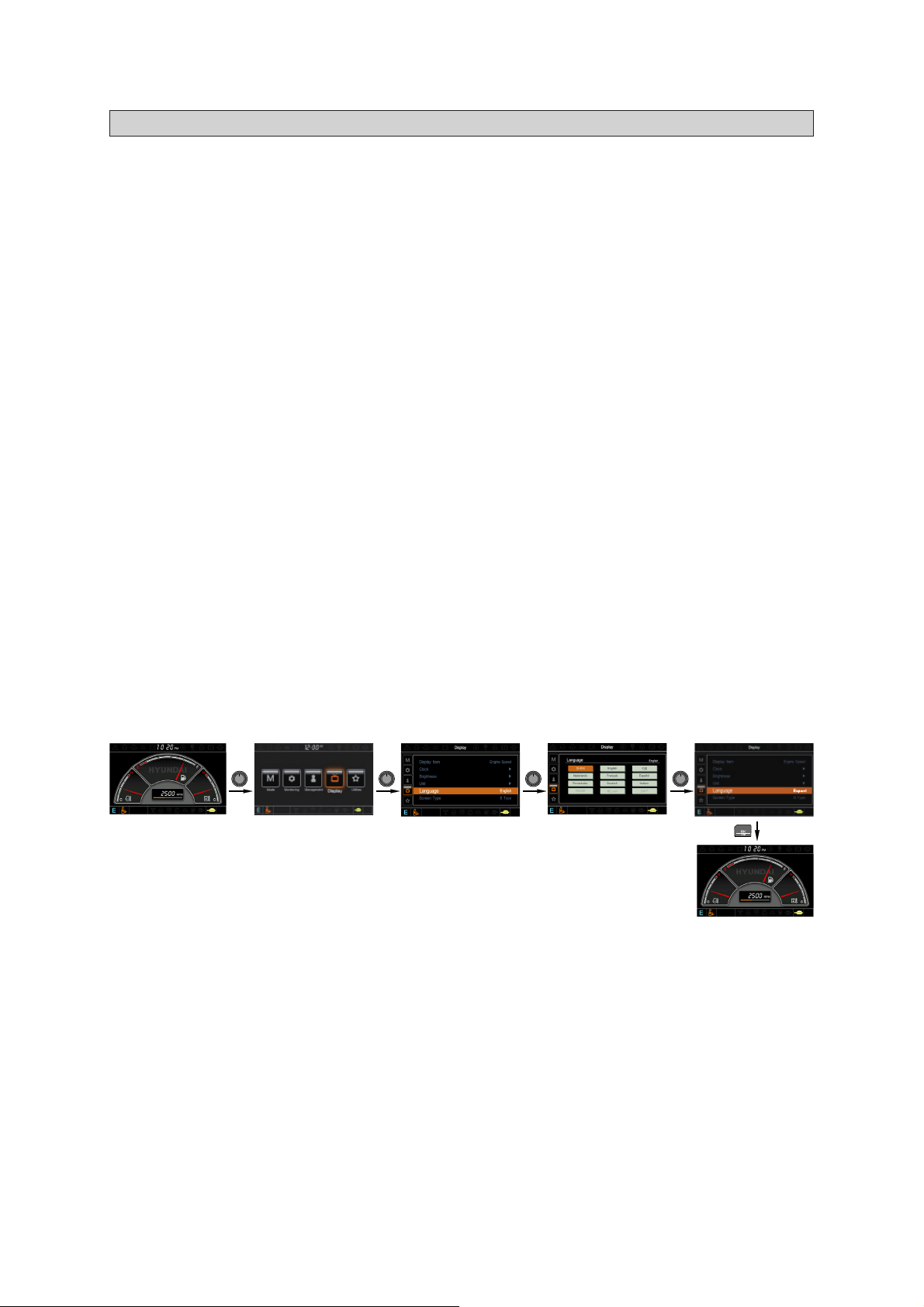
How to adjust the language of cluster (cluster type 1)
BEFORE SERVICING THIS MACHINE
It is the responsibility of the owner and all service and maintenance personnel to avoid accidents and
serious injury by keeping this machine properly maintained.
It also is the responsibility of the owner and all service and maintenance personnel to avoid accidents
and serious injury while servicing the machine.
No one should service or attempt to repair this machine without proper training and supervision.
All service and maintenance personnel should be thoroughly familiar with the procedures and precau-
tions contained in this manual.
All personnel also must be aware of any federal, state, provincial or local laws or regulations covering
the use and service of construction equipment.
The procedures in this manual do not supersede any requirements imposed by federal, state, provin-
cial or local laws.
Hyundai can not anticipate every possible circumstance or environment in which this machine may be
used and serviced.
All personnel must remain alert to potential hazards.
Work within your level of training and skill.
Ask your supervisor if you are uncertain about a particular task. Do not try to do too much too fast.
Use your common sense.
How to adjust the language of cluster (cluster type 1)
※
User can select preferable language and all displays are changed the selected language.
Press Press Press Press
Please refer to the page 3-20 for the cluster.
※
0-2
Page 4

EC REGULATION APPROVED
EC REGULATION APPROVED
·
Noise level (EN474-1 : 2006 and 2000/14/EC) are as followings.
WA : 100
L
L
PA : 71
·
The value of vibrations transmitted by the operator's seat are lower than standard value of (EN474-1
: 2006 and 2002/44/EC)
dB
(EU only)
dB
0-3
Page 5

TABLE TO ENTER SERIAL NO. AND DISTRIBUTOR
TABLE TO ENTER SERIAL NO. AND DISTRIBUTOR
Machine Serial No.
Engine Serial No.
Manufacturing year
Manufacturer
Address
Distributor for U.S.A
Address
Distributor for Europe
Address
Dealer
Address
Hyundai Heavy Industries co., Ltd.
1000, Bangeojinsunhwan-doro, Dong-Ku,
Ulsan 682-792, Korea
Hyundai Heavy Industries U.S.A, Inc
6100 Atlantic Boulevard Norcross
GA 30071
U.S.A
Hyundai Heavy Industries Europe N. V.
Vossendal 11
2240 Geel
Belgium
0-4
Page 6
SAFETY LABELS
1. LOCATION
SAFETY LABELS
1. LOCATION
Always keep these labels clean. If they are lost or damage, attach them again or replace them with
a new label.
37
19
35
34
CAB INSIDE-RH
41
51
50
2
39
43
10
39
16
10
3
15
13
1
14
27
6
1212
26
45
PUMP SCREEN
5
38
BATTERY COVER
9
30
42
7
46
316
36
47
11
49
23
SCREEN PLATE
9
42
4
48
17
29
t
e
k
c
u
B
22
32
20
21
24
52
22
CAB INSIDE-LH
8
16
1828
LH CONSOLE BOX
1 Air cleaner filter
2 Turbocharger cover
3 Radiator cap
4 Fueling
5 Battery accident
6 High pressure hose
7 Hydraulic oil level
8 Hydraulic oil lub
9 Keep clear-rear
10 Lifting eye
11 Name plate
12 Slinging ideogram
13 Keep clear-side
14 Stay fix
15 Shearing-engine hood
16
No step-engine hood and CWT
17 Transporting
18 Low emission engine
19 Control ideogram
20
Ref operator manual-cab RH pillar
21 Hammer
22 Safety front window
23 Alternate exit
24 Air conditioner filter
26 Safety lever
27 Model name
28 Logo (ROBEX)
29 Trade mark (boom)
30 Trade mark (CWT)
31 Reduction gear grease
32 Clamp-locking
34 Service instruction
0-5
1609S0SL01
35 Lifting chart
36 Tie
37 Keep clear-Boom/arm
38 Electric welding
39 Falling
41 Turbocharger
42 Reflecting
43 Accumulator
45 Control ideogram-dozer
46 RCV lever pattern
47 Swing bearing
48 Battery position
49 Beacon lamp
50 Fuel shut off
51 Water separator
52 MCU connector
Page 7
2. DESCRIPTION
AIR CLEANER FILTER
Periodic and proper inspection, cleaning
and change of elements prolong engine
life time and maintain the good performance of engine.
1)
TURBOCHARGER COVER
Do not touch turbocharger or it may
cause severe burn.
2)
RADIATOR CAP
Never open the filler cap while engine
running or at high coolant temperature.
3)
FUELING
Stop the engine when refueling. All
lights or flames shall be kept at a safe
distance while refueling.
4)
2. DESCRIPTION
There are several specific warning labels on this machine please become familiarized with all warning labels.
Replace any safety label that is damaged, or missing.
1)
AIR CLEANER FILTER (item 1)
This warning label is positioned on the air
cleaner cover.
※
Periodic and proper inspection, cleaning
and change of elements prolong engine
life time and maintain the good performance of engine.
TURBOCHARGER COVER (item 2)
2)
This warning label is positioned on the turbocharger cover.
Do not touch turbocharger or it may
cause severe burn.
21070FW01
RADIATOR CAP (item 3)
3)
This warning label is positioned on the radiator.
Never open the filler cap while engine
running or at high coolant temperature.
FUELING (item 4)
4)
This warning label is positioned on the fuel
filler neck.
Stop the engine when refueling. All
lights or flames shall be kept at a safe
distance while refueling.
21070FW02
14070FW03
0-6
21070FW04
Page 8
BATTERY ACCIDENT
Electrolyte containing sulfuric acid cause
severe burns. Avoid being in contact with
skin, eyes or clothes. In the event of
accident flush with sufficient water, call a
physician immediately.
Maintain the electrolyte at the recommended level.
With electrolyte at proper level, less
space may cause the gases to be accumulated in the battery.
Extinguish all smoking materials and
open flames before checking the battery.
Do not use matches, lighters or torches
as a light source near the battery for the
probable presence of explosive gas.
Do not allow unauthorized personnel to
change the battery or to use booster
cables.
For safety from electric shock, do not battery terminal with a wet hand.
5)
HIGH PRESSURE HOSE
Escaping fluid under pressure can penetrate the skin causing serious injury.
Study the service manual before service
job.
6)
BATTERY ACCIDENT (item 5)
5)
This warning label is positioned on the battery cover.
Electrolyte containing sulfuric acid cause
severe burns. Avoid being in contact with
skin, eyes or clothes. In the event of
accident flush with sufficient water, call a
physician immediately.
※
Maintain the electrolyte at the recommended level.
With electrolyte at proper level, less
space may cause the gases to be accumulated in the battery.
Extinguish all smoking materials and
open flames before checking the battery.
Do not use matches, lighters or torches
as a light source near the battery for the
probable presence of explosive gas.
Do not allow unauthorized personnel to
change the battery or to use booster
cables.
For safety from electric shock, do not battery terminal with a wet hand.
36070FW05
HIGH PRESSURE HOSE (item 6)
6)
These warning labels are positioned in the
front of upper frame and on the screen
plate.
Escaping fluid under pressure can penetrate the skin causing serious injury.
※
Study the service manual before service
job.
14070FW29
0-7
Page 9
LIFTING EYE
Do not lift the machine by using lifting
eyes on the counterweight or the lifting
eyes may be subject to overload causing
its breaking and possible personal injury.
See page 5-8 for proper lifting method of
the machine.
10)
HYDRAULIC OIL LUBRICATION
Do not mix with different brand oils.
Never open the filler cap while high temperature.
Loosen the cap slowly and release internal pressure completely.
8)
KEEP CLEAR-REAR
To prevent serious personal injury or
death keep clear or machine swing radius.
Do not deface of remove this label from
the machine.
9)
HYDRAULIC OIL LEVEL
Place the bucket on the ground whenever
servicing the hydraulic system.
Check oil level on the level gauge.
Refill the recommended hydraulic oil up
to specified level if necessary.
7)
HYDRAULIC OIL LEVEL (item 7)
7)
This warning label is positioned on the
screen plate.
Place the bucket on the ground whenever
servicing the hydraulic system.
※
Check oil level on the level gauge.
※
Refill the recommended hydraulic oil up
to specified level if necessary.
HYDRAULIC OIL LUBRICATION (item 8)
8)
This warning label is positioned on the top
of the hydraulic tank.
※
Do not mix with different brand oils.
Never open the filler cap while high temperature.
Loosen the cap slowly and release internal pressure completely.
21070FW07
KEEP CLEAR-REAR (item 9)
9)
This warning label is positioned on the rear
of counterweight.
To prevent serious personal injury or
death keep clear or machine swing radius.
Do not deface of remove this label from
the machine.
LIFTING EYE (item 10)
10)
This warning label is positioned on the
counterweight.
Do not lift the machine by using lifting
eyes on the counterweight or the lifting
eyes may be subject to overload causing
its breaking and possible personal injury.
※
See page 5-8 for proper lifting method of
the machine.
14070FW08
21090FW09
21070FW10
0-8
Page 10
SHEARING-ENGINE HOOD
Don't open the engine hood during the
engine's running.
Don't touch exhaust pipe or it may cause
severe burn.
KEEP CLEAR-SIDE
To prevent serious personal injury or
death keep clear of machine swing radius.
Do not deface or remove this label from
the machine.
STAY FIX
Be sure to support the stay when the
door needs to be opened.
Be careful that the opened door may be
closed by the external or natural force
like strong wind.
13)
11)
12)
KEEP CLEAR-SIDE (item 13)
11)
This warning label is positioned on the LH
side cover.
To prevent serious personal injury or
death keep clear of machine swing radius.
Do not deface or remove this label from
the machine.
STAY FIX (item 14)
12)
This warning label is positioned on the both
side cover.
Be sure to support the stay when the
door needs to be opened.
Be careful that the opened door may be
closed by the external or natural force
like strong wind.
21070FW13
SHEARING-ENGINE HOOD (item 15)
13)
This warning label is positioned on the
engine hood.
Don't open the engine hood during the
engine's running.
Don't touch exhaust pipe or it may cause
severe burn.
21070FW14
21070FW15
0-9
Page 11
REF OPERATOR MANUAL
Study the operator's manual before starting and operating machine.
TRANSPORTING
Study the operator's manual before
transporting the machine, if provided and
tie down arm and track to the carrier with
lashing wire.
See page 5-7 for details.
CONTROL IDEOGRAM
Check the machine control pattern for
conformance to pattern on this label. If
not, change label to match patte rn
before operating machine.
Failure to do so could result in injury or
death.
See page 4-20 for details.
NO STEP-ENGINE HOOD/CWT
Do not step on the engine hood and
counterweight.
17)
14)
15)
16)
14)
NO STEP-ENGINE HOOD/CWT (item 16)
These warning labels are positioned on the
engine hood and counterweight.
Do not step on the engine hood and
counterweight.
TRANSPORTING (item 17)
15)
This warning label is positioned right side
of upper frame.
Study the operator's manual before
transporting the machine, if provided and
tie down arm and track to the carrier with
lashing wire.
See page 5-7 for details.
21070FW16
CONTROL IDEOGRAM (item 19)
16)
This warning label is positioned in right
window of the cab.
Check the machine control pattern for
conformance to pattern on this label. If
not, change label to match pattern
before operating machine.
Failure to do so could result in injury or
death.
See page 4-20 for details.
REF OPERATOR MANUAL (item 20)
17)
This warning label is positioned on the right
side window of the cab.
Study the operator's manual before starting and operating machine.
14070FW17
36070FW19
0-10
21070FW22
Page 12
MAX HEIGHT
Serious injury or death can result from
contact with electric lines.
An electric shock being received by
merely coming into the vicinity of an
electric lines, the minimum distance
should be kept considering the supply
voltage as page 1-7.
INTERFERENCE
Be careful to operate machine equipped
with quick clamp or extensions.
Bucket may hit cab or boom, boom cylinders when it reached vicinity of them.
18)
19)
ALTERNATE EXIT
The rear window serves us an alternate
exit.
To remove rear window, pull the ring and
push out the glass.
SAFETY FRONT WINDOW
Be careful that the front window may be
promptly closed.
21
20)
MAX HEIGHT (item 20)
18)
This warning label is positioned on the right
side window of the cab.
Serious injury or death can result from
contact with electric lines.
An electric shock being received by
merely coming into the vicinity of an
electric lines, the minimum distance
should be kept considering the supply
voltage as page 1-7.
INTERFERENCE (item 20)
19)
This warning label is positioned on the
right side window of the cab.
Be careful to operate machine equipped
with quick clamp or extensions.
Bucket may hit cab or boom, boom cylinders when it reached vicinity of them.
21070FW23
SAFETY FRONT WINDOW (item 22)
20)
This warning label is positioned on the both
side window of the cab.
Be careful that the front window may be
promptly closed.
ALTERNATE EXIT (item 23)
21)
This warning label is positioned on the
inside of rear window.
※
The rear window serves us an alternate
exit.
※
To remove rear window, pull the ring and
push out the glass.
21090FW62
21070FW24
0-11
21070FW25
Page 13
AIR CONDITIONER FILTER
Periodic and proper inspection, cleaning
and change of filter prolong air conditioner life time and maintain good performance.
SAFETY LEVER
Before you get off the machine be sure
to place the safety lever LOCKED position.
22)
23)
REDUCTION GEAR GREASE
Grease is under high pressure.
Grease coming out of the grease plug
under pressure can penetrate the body
causing injury or death.
CLAMP-LOCKING
Serious injury or death can result from
dropping bucket.
Operating the machine with quick clamp
switch unlocked or without safety pin of
moving hook can cause the bucket to
drop off.
24)
25)
AIR CONDITIONER FILTER (item 24)
22)
This warning label is positioned on the air
conditioner cover.
※
Periodic and proper inspection, cleaning
and change of filter prolong air conditioner life time and maintain good performance.
SAFETY LEVER (item 26)
23)
This warning label is positioned on the
cover of the safety lever.
Before you get off the machine be sure
to place the safety lever LOCKED position.
21070FW26
REDUCTION GEAR GREASE (item 31)
24)
This warning label is positioned in the front
of upper frame.
Grease is under high pressure.
Grease coming out of the grease plug
under pressure can penetrate the body
causing injury or death.
CLAMP-LOCKING (item 32)
25)
This warning label is positioned on the right
side window of cab.
Serious injury or death can result from
dropping bucket.
Operating the machine with quick clamp
switch unlocked or without safety pin of
moving hook can cause the bucket to
drop off.
30007A1FW07A
21070FW35
14070FW60
0-12
Page 14

TIE
Make sure no personal are standing
close to the tow rope.
See page 4-23 for detail.
KEEP CLEAR-BOOM/ARM
Serious injury or death can result from
falling of the attachment.
To prevent serious injury or death, keep
clear the underneath of attachment.
26)
27)
ELECTRIC WELDING
Before carrying out any electric welding
on this machine, follow the below procedure.
See page 6-41 for detail.
28)
TIE (item 36)
26)
This warning label is positioned on the
lower frame.
Make sure no personal are standing
close to the tow rope.
See page 4-23 for detail.
KEEP CLEAR-BOOM/ARM (item 37)
27)
This warning label is positioned on both
side of the arm.
Serious injury or death can result from
falling of the attachment.
To prevent serious injury or death, keep
clear the underneath of attachment.
4507A0FW02
ELECTRIC WELDING (item 38)
28)
This warning label is positioned on the battery cover.
Before carrying out any electric welding
on this machine, follow the below procedure.
Pull the connector out of all electric con-
trol units.
-
Connector the ground lead of the welding equipment as close to the welding
point as possible.
※
See page 6-41 for detail.
14070FW31
W A R N I N G
·Before carrying out any electric welding on this
machine
- Pull the connectors out of all electronic control
units.
- Connect the ground lead of the welding equipment
as close to the welding point as possible.
·Read the instructions in operator's manual for
details.
7807AFW20
0-13
Page 15
TURBOCHARGER
In order to prevent turbocharger failure,
please allow more than 5 minutes' cool
down period (no load low idle operation)
before shutting the engine off.
REFLECTING
To prevent serious personal injury or
death keep clear of machine swing radius.
Do not deface or remove this label from
the machine.
30)
31)
FALLING
Falling is one of the major cause of personal injury.
Be careful of slippery conditions on the
platforms, steps and handrails when
standing on the machine.
29)
FALLING (item 39)
29)
These warning labels are positioned on the
top of the hydraulic tank and counterweight.
Falling is one of the major cause of personal injury.
Be careful of slippery conditions on the
platforms, steps and handrails when
standing on the machine.
TURBOCHARGER (item 41)
30)
This warning label is positioned on the right
window of the cab.
In order to prevent turbocharger failure,
please allow more than 5 minutes' cool
down period (no load low idle operation)
before shutting the engine off.
14070FW30
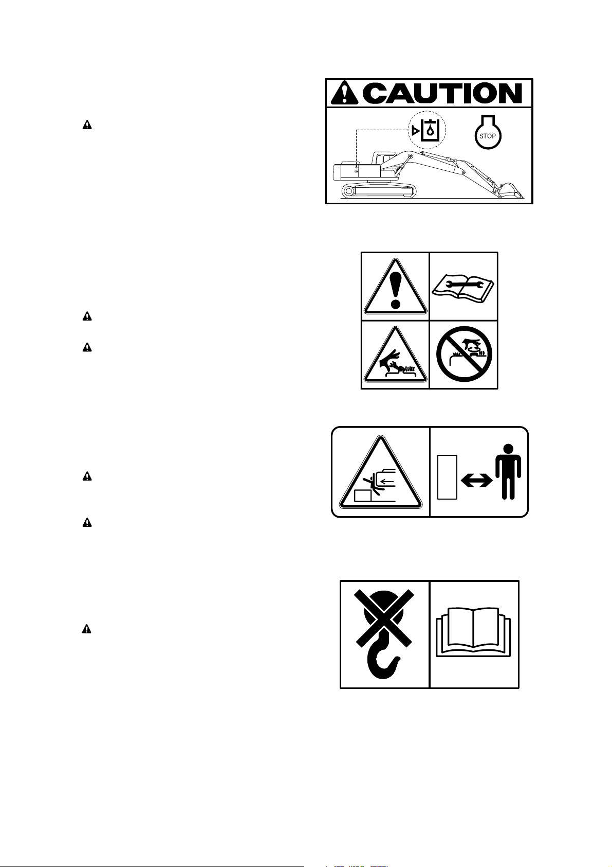
C A U T I O N
In order to prevent turbocharger failure,
please allow more than 5 minutes' cool
down period(no load low idle operation)
before shutting the engine off.
REFLECTING (item 42)
31)
This warning label is positioned on the rear
of counterweight.
To prevent serious personal injury or
death keep clear of machine swing radius.
Do not deface or remove this label from
the machine.
7807AFW20
21090FW70
0-14
Page 16
ACCUMULATOR
The accumulator is filled with high-pressure nitrogen gas, and it is extremely
dangerous if it is handled in the wrong
way. Always observe the following precautions.
Never make any hole in the accumulator
expose it to flame or fire.
Do not weld anything to the accumulator.
When carrying out disassembly or maintenance of the accumulator, or when disposing of the accumulator, it is necessary to release the gas from the accumulator. A special air bleed valve is necessary for this operation, so please contact your Hyundai distributor.
32)
SWING BEARING
See page 6-32 for details.
34)
RCV LEVER PATTERN
See page 4-34 for details.
33)
ACCUMULATOR (item 43)
32)
This warning label is positioned on the
accumulator of the solenoid valve.
※
The accumulator is filled with high-pressure nitrogen gas, and it is extremely
dangerous if it is handled in the wrong
way. Always observe the following precautions.
Never make any hole in the accumulator
expose it to flame or fire.
Do not weld anything to the accumulator.
※
When carrying out disassembly or maintenance of the accumulator, or when disposing of the accumulator, it is necessary to release the gas from the accumulator. A special air bleed valve is necessary for this operation, so please contact your Hyundai distributor.
1107A0FW46
RCV LEVER PATTERN (item 46)
33)
This warning label is positioned on the
screen plate.
※
See page 4-34 for details.
SWING BEARING (item 47)
34)
This warning label is positioned in the front
of swing ring gear.
※
See page 6-32 for details.
14W90FW47
38090FW02
0-15
Page 17

BATTERY POSITION
35)
BEACON LAMP
Make sure the beacon lamp maintains a
vertical position.
A horizontal position can result in a
decrease in life time of the lamp due to
the infiltration of foreign substances such
as dust or water.
While the machine transfer, the beacon lamp
is easy to break. In that case, change the
position of the lamp to the horizontal.
36)
FUEL SHUT OFF
Fill only the hydraulic oil.
Do not fill the diesel fuel.
37)
WATER SEPARATOR
In order to protect high pressure fuel
system, please drain water in water
separator before starting the engine.
38)
35)
BATTERY POSITION (item 48)
This warning label is positioned right side of
tool box.
BEACON LAMP (item 49)
36)
This warning label is positioned on the right
outside of the cabin.
※
Make sure the beacon lamp maintains a
vertical position.
A horizontal position can result in a
decrease in life time of the lamp due to
the infiltration of foreign substances such
as dust or water.
While the machine transfer, the beacon lamp
※
is easy to break. In that case, change the
position of the lamp to the horizontal.
38090FW03
140Z90FW49
FUEL SHUT OFF (item 50)
37)
This warning label is positioned on the left
side of the hydraulic tank.
※
Fill only the hydraulic oil.
※
Do not fill the diesel fuel.
WATER SEPARATOR (item 51)
38)
This warning label is positioned in right window of the cab.
In order to protect high pressure fuel
system, please drain water in water
separator before starting the engine.
140WH90FW51
In order to protect high pressure fuel system,
please drain water in water separator before
starting the engine.
210N90FW50
0-16
Page 18

MCU CONNECTOR
MCU communicates the machine data with
Laptop computer through RS232 service
socket.
See page 3-60 for details.
39)
39)
MCU CONNECTOR (item 52)
This warning label is positioned on the low
cover of the air conditioner in the cab.
※
MCU communicates the machine data with
Laptop computer through RS232 service
socket.
See page 3-60 for details.
※
1409S0FW52
0-17
Page 19

MACHINE DATA PLATE
MACHINE DATA PLATE
1000, BANGEOJINSUNHWAN-DORO, DONG-GU, ULSAN 682-792, KOREA
EQUIPMENT
1
2
MODEL
SERIAL-NUMBER
3
DO NOT DEFACE OR REMOVE THIS PLATE
OPERATING WEIGHT
ENGINE POWER(PS/KW/rpm)
1
4
2
5
3
1000, BANGEOJINSUNHWAN-DORO, DONG-GU, ULSAN 682-792, KOREA
EQUIPMENT
MODEL
SERIAL-NUMBER
DO NOT DEFACE OR REMOVE THIS PLATE
OPERATING WEIGHT
ENGINE POWER(PS/KW/rpm)
MFG. YEAR
FOR EU ONLY
1 Equipment
2 Model name
The machine serial number assigned to this particular machine and should be used when request-
※
3 Serial number
4 Operating weight
5 Engine power
6 Manufacturing year
ing information or ordering service parts for this machine from your authorized HYUNDAI dealer.
The machine serial number is also stamped on the frame.
4
5
6
21090FW10
0-18
Page 20
GUIDE
1. DIRECTION
2. SERIAL NUMBER
MACHINE SERIAL NUMBER
4. SYMBOLS
Important safety hint.
It indicates matters which can cause the great loss on the machine or the surroundings.
It indicates the useful information for operator.
1)
ENGINE SERIAL NUMBER
2)
3.
INTENDED USE
GUIDE
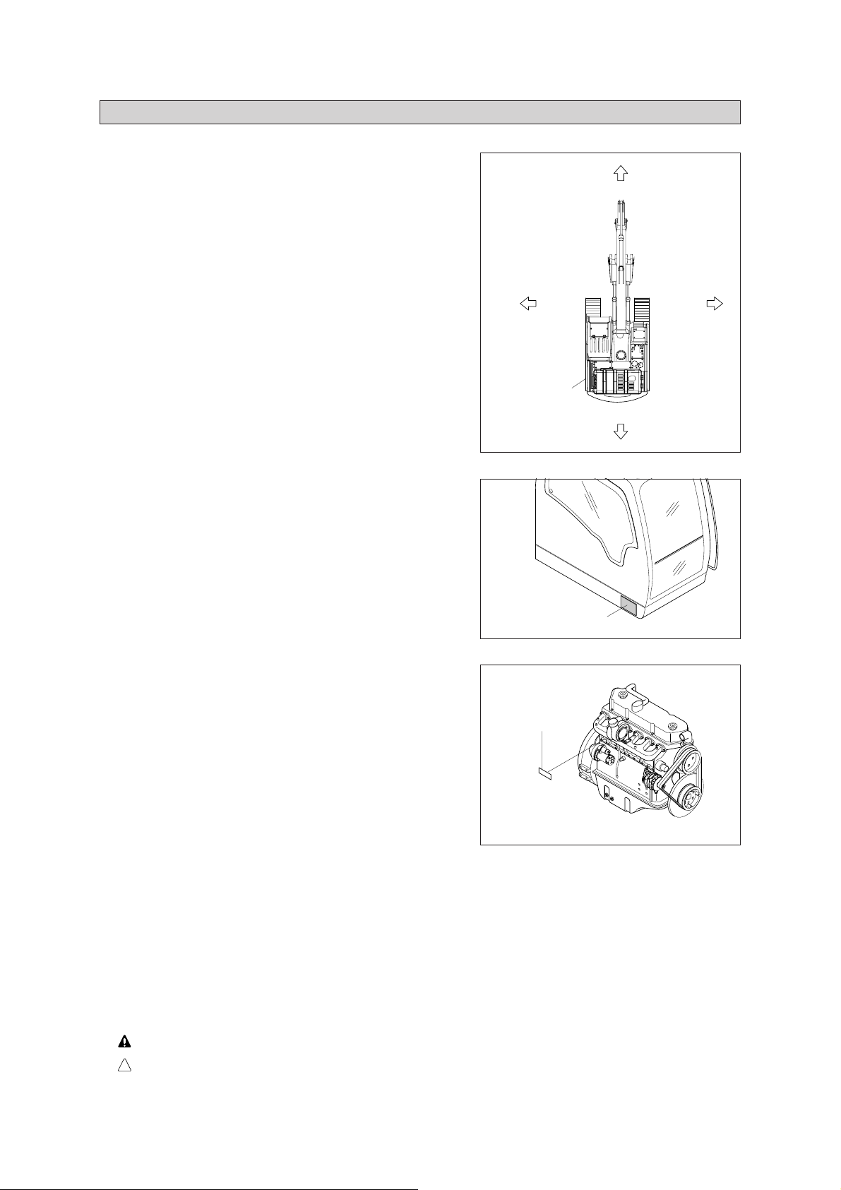
1. DIRECTION
The direction of this manual indicate forward, back-
ward, right and left on the standard of operator
when the travel motor is in the rear and machine is
on the traveling direction.
2. SERIAL NUMBER
Inform following when you order parts or the
machine is out of order.
1)
MACHINE SERIAL NUMBER
The numbers are located below the right window
of the operator's cab.
Forward
Travel motor
Backward
Machine serial No.
RightLeft
16090SG01
21090SN02
ENGINE SERIAL NUMBER
2)
The numbers are located on the engine name
plate.
3.
INTENDED USE
Engine serial No.
This machine is designed to be used mainly for the following work.
- Digging work
- Loading work
- Smoothing work
- Ditching work
※
Please refer to the section 4 (efficient working method) further details.
4. SYMBOLS
Important safety hint.
It indicates matters which can cause the great loss on the machine or the surroundings.
17W9S0SN01
※
It indicates the useful information for operator.
0-19
Page 21
1. BEFORE OPERATING THE MACHINE
SAFETY HINTS
1. BEFORE OPERATING THE MACHINE
Think-safety first.
In special situation, wear protective clothing
including a safety helmet, safety shoes, gloves,
safety glasses and ear protection as required by
the job condition.
Almost every accident is caused by disregarding the simple and fundamental safety
hints.
Be sure to understand thoroughly all about the
operator's manual before operating the
machine.
Proper care is your responsibility.
SAFETY HINTS
13031SH01
Fully understand the details and process of the
construction before starting the work.
If you find anything dangerous on the job,
consult with the job supervisor for the preventive measures before operating the machine.
Do not operate when tired, or after drinking
alcoholic beverages or any type of drugs.
13031SH02
13031SH03
1-1
13031SH05
Page 22
Check daily according to the operation manual.
Repair the damaged parts and tighten the loosened bolts.
Check for leakage of engine oil, hydraulic oil,
fuel and coolant.
Keep machine clean, clean machine regularly.
13031SH05
Do not operate the machine if it requires repairs.
Operate after complete repair.
Be prepared if a fire starts.
Keep a fire extinguisher handy and emergency
numbers for a fire department near your telephone.
13031SH06
13031SH07
1-2
13031SH08
Page 23

PROTEC TIO N AGAINS T FALLI NG OR
FLYING OBJECTS
UNAUTHORIZED MODIFICATION
PREPARE FOR EMERGENCY
PROTECTION AGAINST FALLING OR
FLYING OBJECTS
If there is any danger of falling or flying objects
hitting the operator, install protective guards in
place to protect the operator as required for
each particular situation.
Be sure to close the front window before commencing work.
Make sure to keep all persons other than operator outside the range of falling or flying objects.
In case you need top guard, front guard and
FOPS (falling object protective structure),
please contact Hyundai distributor in Europe.
UNAUTHORIZED MODIFICATION
Any modification made without authorization
from Hyundai can create hazards.
Top guard
Front guard
21091SH01
Before making a modification, consult your
Hyundai distributor. Hyundai will not be responsible for any injury or damage caused by any
unauthorized modification.
PREPARE FOR EMERGENCY
Only in case of emergency, use the installed
hammer for breaking the windshield of the cab,
and then exit carefully.
Be sure you know the phone numbers of persons you should contact in case of an emergency.
Hammer
1-3
21091SH02
Page 24

ROTATING BEACON
PRECAUTIONS FOR ATTACHMENTS
SAFETY RULES
Only
ROTATING BEACON
When you operate a machine on a road or
beside a road, a rotating beacon is required to
avoid any traffic accident.
Please contact your Hyundai distributor to install
it.
PRECAUTIONS FOR ATTACHMENTS
When installing and using an optional attachment, read the instruction manual for the attachment and the information related to attachments
in this manual.
Do not use attachments that are not authorized
by Hyundai or your Hyundai distributor. Use of
unauthorized attachments could create a safety
problem and adversely affect the proper operation and useful life of the machine.
Beacon
21091SH03
Any injuries, accidents, product failures resulting
from the use of unauthorized attachments are
not the responsibility of Hyundai.
The stability of this machine is enough to be
used for general work. When you operate this
machine, allow for the lifting capacity tables. If
you want to use other special applications (not
covered in this manual), you have to attach
additional counterweight or be cautious while
running the machine.
SAFETY RULES
Only trained and authorized personnel can
operate and maintain the machine.
Follow all safety rules, precautions and instructions when operating or performing maintenance on the machine.
When working with another operator or a person on worksite traffic duty, be sure all personnel understand all hand signals that are to be
used.
1-4
Page 25
SAFETY FEATURES
Never
Always
MACHINE CONTROL PATTERN
CALIFORNIA PROPOSITION 65
The wrong loading method can result in serious bodily injury or death.
SAFETY FEATURES
Be sure all guards and covers are in their proper position. Have guards and covers repaired if
damaged.
Use safety features such as safety lock and
seat belts properly.
Never remove any safety features.
Always
keep them in good operating condition.
Improper use of safety features could result in
serious bodily injury or death.
MACHINE CONTROL PATTERN
Check machine control pattern for conformance
to pattern on label in cab.
If not, change label to match pattern before
operating machine.
Failure to do so could result in injury.
CALIFORNIA PROPOSITION 65
Diesel engine exhaust and some of its constituents are known to the State of California to
cause cancer, birth defects and other reproductive harm.
This product contains or emits chemicals known
to the State of California to cause cancer or
birth defects or other reproductive harm.
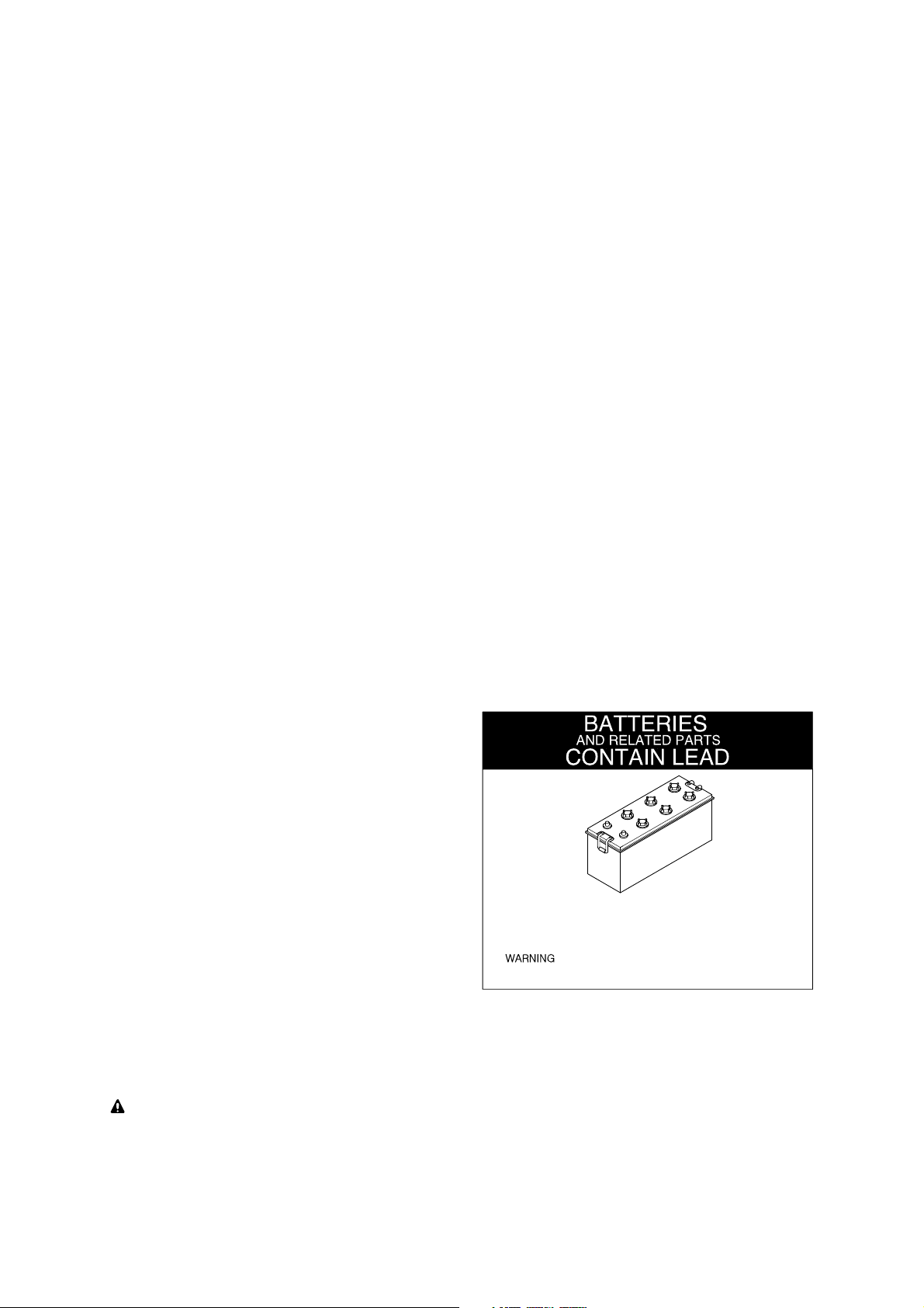
Battery posts, terminals and related accessories contain lead and lead compounds.
WASH HANDS AFTER HANDLING
WASH HANDS
AFTER HANDLING !
contain lead and lead compounds,chemicals known to the
State of California to cause cancer and reproductive harm.
: Battery posts, terminals and related accessories
13031SH55
Do not load the machine with the lifting eyes on
the counterweight.
The wrong loading method can result in serious bodily injury or death.
1-5
Page 26
2. DURING OPERATING THE MACHINE
2. DURING OPERATING THE MACHINE
Use the handle and footstep when getting on or
off the machine.
Do not jump on or off the machine.
Sound the horn to warn nearby personnel
before operating the machine.
Remove all the obstacles like frost on the window before operating the machine for the good
visibility.
13031SH09
Operate carefully to make sure all personnel or
obstacles are clear within the working range of
the machine.
Place safety guards if necessary.
When using the work equipment, pay attention
to job site.
13031SH10
13031SH11
1-6
13031SH12
Page 27
Provide proper ventilation when operating
engine in a closed area to avoid the danger of
exhaust gases.
Check the locations of underground gas
pipes or water line and secure the safety before
operation.
13031SH13
The operating near the electrical lines is very
dangerous.
Operate within safe working range permitted as
below.
Supply voltage
6.6
kV
33.0
kV
66.0
kV
154.0
kV
275.0
kV
Min safe separation
3m (10 ft)
4m (13 ft)
5
m
(16 ft)
m
(26 ft)
8
10m (33 ft)
If the machine touches the electric power lines,
keep sitting on the operator's seat and make
sure the personnel on the ground not to touch
the machine until turning off the electric current. Jump off the machine without contacting
the machine when you need to get off.
13031SH14
13031SH15
1-7
13031SH16
Page 28
Watch out for obstacles.
Be particularly careful to check the machine
clearance during the swing.
When using the machine as breaker or
working in a place where stones may fall down,
cab roof guard and head guard should be provided for proper protection.
13031SH17
Avoid operating on a cliff or soft ground as there
is danger of rolling over.
Make sure to get off easily as keeping the track
at a right angle and putting the travel motor into
the backward position when working on a cliff or
soft ground inevitably.
Operate for the lifting work considering the
capacity of machine, weight and width of the
load.
Be careful not to lift exceeding the machine
capacity as it can be the cause of machine
damage and safety accident.
13031SH18
13031SH19
1-8
13031SH20
Page 29
The operation on a slope is dangerous.
Avoid operating the machine on a slope of over
10 degree.
Operate the machine after making ground flat
when operation is required on a slope.
13031SH21
The swing on the slope can be danger of
rolling over.
Do not operate to swing the machine with the
bucket loaded on a slope since the machine
may lose its balance under such an instance.
Avoid parking and stopping on a slope.
Lower the bucket to the ground and block the
track when parking.
13031SH22
13031SH23
1-9
13031SH24
Page 30
Avoid traveling in a cross direction on a slope as
it can cause the danger of rolling over and sliding.
Traveling on a slope is dangerous.
Be sure to operate slowly when traveling down
a slope and maintain the bucket at a height of
20~30
cm
(1 ft) above the ground so that it can
be used as brake in an emergency.
13031SH25
Steering of the machine while traveling on a
slope is dangerous.
When an inevitable turning of direction is
required, turn on the flat and solid ground.
The engine angularity limits are 35 degree.
Do not operate by more than the engine limits
in any case.
20~30
cm
13031SH26
13031SH27
1-10
35。
13031SH28
Page 31

Before traveling the machine, sound the horn
to warn nearby personnel.
Operate forward and backward correctly with
confirming the location of the travel motor.
Slow down when traveling through obstacles or
uneven ground.
13031SH29
When working on soft ground, place mats or
wood boards on the ground to prevent the
machine sinking.
When operating in water or when crossing shallow, check the bed soil condition and depth and
flow speed of water, then proceed taking care
that water is not above carrier roller.
13031SH30
13031SH31
1-11
13031SH32
Page 32

MOUNTING AND DISMOUNTING
Never
Never
KEEP RIDERS OFF MACHINE
MOUNTING AND DISMOUNTING
Never jump on or off the machine.
Never get on or off
a moving machine.
When mounting or dismounting, always face the
machine and use the handrails, machine or track
frame steps, and track shoes. Additional track frame
step can be fitted for wider optional shoe. In this case
please contact your Hyundai distributor.
Do not hold any control levers when getting on or off
the machine.
Ensure safety by always maintaining at least threepoint contact of hands and feet with the handrails,
steps or track shoes.
Always remove any oil or mud from the handrails,
steps and track shoes. If they are damaged, repair
them and tighten any loose bolts.
If grasping the door handrail when mounting or dismounting or moving on the track, open and lock the
door securely in the open position. Otherwise, the
door may move suddenly, causing you to lose balance
and fall.
KEEP RIDERS OFF MACHINE
Riders on a machine are subject to injury such as
being struck objects and being thrown off the
machine.
Only allow the operator on the machine. Keep riders
off.
14071FW05/06
1-12
Page 33

3. DURING MAINTENANCE
3. DURING MAINTENANCE
Stop the engine immediately when the trouble
of the machine is found.
Inspect immediately the cause of trouble such
as vibration, overheating and trouble in the cluster then repair.
Park on a flat place and stop the engine for
inspecting and repairing. Properly TAG
machine is not operational. (remove start key)
Extreme care shall be taken during maintenance work. Parts may require additional safe
guard.
13031SH33
ON THE
INSPECTION
Do not remove the radiator cap from hot engine.
Open the cap after the engine cools, below 50
°C (122 °F) to prevent personal injury from heated coolant spray or steam.
Do not work below the machine.
Be sure to work with proper safety supports.
Do not depend on the hydraulic cylinders to
hold up the equipment and attachment.
13031SH34
13031SH35
1-13
13031SH36
Page 34

There is the danger of fire in fuel and oil.
Store in cool and dry area, away from any open
flames.
Do not touch exhaust pipe, or may cause
severe burn.
13031SH37
Do not open the engine hood and covers while
the engine is running.
Be careful of not hitting the edges when you
service engine.
13031SH38
13031SH39
1-14
13031SH40
Page 35

Be careful that the front window may be prompt-
HIGH PRESSURE GAS
LIFT EYES CAN FAIL
ly closed.
Be sure to support stay, when the side door
needs to be opened.
Be careful that the open side door may closed
by the external or natural force like strong wind.
The antislip protection should be replaced if
they have become worn or have been printed
over.
Be sure to free of oil, water and grease etc.
13031SH41
Be careful of not touching slip, fall down etc.,
when you work at the upper frame to service
engine and/or other component.
HIGH PRESSURE GAS
Contain high pressure gas.
To avoid explosion and personal injury, do not
expose to fire, do not weld, do not drill.
Relieve pressure before discharging.
13031SH42
13031SH43
21091SH08
LIFT EYES CAN FAIL
Lift eyes or tank can fail when lifting tank
taining fluids resulting in possible personal injury.
Drain tank of all fluids before lifting.
con-
1-15
Page 36

4. PARKING
4. PARKING
When leaving the machine after parking,
lower the bucket to the ground completely and
put the safety lever at parking position then
remove the key.
Lock the cab door.
Park the machine in the flat and safe place.
13031SH44
P
Hope you can work easily and safely
observing safety rules.
For safe operation, observe all safety rules.
13031SH45
13031SH46
1-16
Page 37

1. MAJOR COMPONENT
SPECIFICATIONS
R160LC-9S
1)
1. MAJOR COMPONENT
R160LC-9S
1)
SPECIFICATIONS
Tool box Fuel tank Hydraulic tank Main pump
Engine
Oil cooler
Radiator
Bucket cylinder
Side cutter
Tooth Turning joint Swing motor
Control link
Control rod
Bucket
Boom cylinderBoomArm cylinderArm
Idler
Carrier roller
Cab
Track
Track roller
Main control valve
Muffler
Travel motor
Sprocket
Counterweight
2-1
1609S2SP01
Page 38

2. SPECIFICATIONS
R160LC-9S
·
5.1 m (16' 9") BOOM and 2.6 m (8' 6") ARM
1)
2. SPECIFICATIONS
R160LC-9S
1)
5.1 m (16' 9") BOOM and 2.6 m (8' 6") ARM
I(I')
C
E
G
t
e
k
c
u
B
F
J
K
N
A
Description Unit Specification
Operating weight
Bucket capacity (SAE heaped), standard
Overall length A
kg (lb)
m3 (yd3)
17800 (39240)
0.70 (0.92)
8650 (28' 5")
Overall width, with 600 mm shoe B 2590 ( 8' 6")
D
H
M
B(L)
16092SP02
Overall height C 2990 ( 9' 10")
Superstructure width D 2475 ( 8' 1")
Overall height of cab E 2980 ( 9' 9")
Ground clearance of counterweight F 1055 ( 3' 6")
Engine cover height G 2315 ( 7' 7")
Minimum ground clearance H 460 ( 1' 6")
mm (ft-in)
Rear-end distance I 2480 ( 8' 2")
Rear-end swing radius I' 2530 ( 8' 4")
Distance between tumblers J 3170 (10' 5")
Undercarriage length K 3960 (13' 0")
Undercarriage width L 2590 ( 8' 6")
Track gauge M 1990 ( 6' 6")
Track shoe width, standard N 600 (24")
Travel speed (low/high)
Swing speed
Gradeability
Ground pressure (600
mm
shoe)
km/hr (mph)
rpm
Degree (%
) 30 (58)
kgf/cm2(psi)
3.2/5.5 (2.0/3.4)
11.3
0.43 (6.11)
Max traction force
2-2
kg (lb)
17000 (37500)
Page 39

R160LC-9S
· 5.1 m (16' 9")
YDRAULIC ADJUSTABLE BOOM AND
2.6 m (8' 6") ARM
2)
R160LC-9S
2)
5.1 m (16' 9") H H
YDRAULIC ADJUSTABLE BOOM AND
2.6 m (8' 6") ARM
C
A
Description Unit Specification
Operating weight
Bucket capacity (SAE heaped), standard
Overall length A
mm
Overall width, with 600
shoe B 2590 ( 8' 6")
J
K
I(I')
kg (lb)
m3 (yd3)
D
E
G
F
H
M
N
B(L)
16092SP03
18290 (40320)
0.70 (0.92)
8610 ( 28' 3")
Overall height C 3060 ( 10' 0")
Superstructure width D 2475 ( 8' 1")
Overall height of cab E 2980 ( 9' 9")
Ground clearance of counterweight F 1055 ( 3' 6")
Engine cover height G 2315 ( 7' 7")
Minimum ground clearance H 460 ( 1' 6")
Rear-end distance I 2480 ( 10' 5")
Rear-end swing radius I' 2530 ( 8' 4")
Distance between tumblers J 3170 (10' 5")
Undercarriage length K 3960 (13' 0")
Undercarriage width L 2590 ( 8' 6")
Track gauge M 1990 ( 6' 6")
Track shoe width, standard N 600 (24")
Travel speed (low/high)
Swing speed
Gradeability
mm
Ground pressure (600
shoe)
mm (ft-in)
km/hr (mph)
rpm
Degree (%
kgf/cm2(psi)
) 30 (58)
3.2/5.5 (2.0/3.4)
11.3
0.44 (6.11)
Max traction force
2-3
kg (lb)
17000 (37500)
Page 40

C
R160LCD-9S
·
5.1 m (16' 9") BOOM and 2.6 m (8' 6") ARM
3)
R160LCD-9S
3)
5.1 m (16' 9") BOOM and 2.6 m (8' 6") ARM
I(I')
E
G
t
e
k
c
u
B
J
K
F
P
O
Q
N
A
Description Unit Specification
Operating weight
Bucket capacity (SAE heaped), standard
Overall length A
kg (lb)
m3 (yd3)
18800 (41450)
0.70 (0.92)
9100 (29' 10")
Overall width, with 600 mm shoe B 2590 ( 8' 6")
D
H
M
B(L)
16092SP04
Overall height C 2990 ( 9'10")
Superstructure width D 2475 ( 8' 1")
Overall height of cab E 2980 ( 9' 9")
Ground clearance of counterweight F 1055 ( 3' 6")
Engine cover height G 2315 ( 7' 7")
Minimum ground clearance H 460 ( 1' 6")
Rear-end distance I 2480 ( 8' 2")
mm (ft-in)
Rear-end swing radius I' 2530 ( 8' 4")
Distance between tumblers J 3170 (10' 5")
Undercarriage length K 3960 (13' 0")
Undercarriage width L 2590 ( 8' 6")
Track gauge M 1990 ( 6' 6")
Track shoe width, standard N 600 (24")
Height of blade O 640 (2' 1")
Ground clearance of blade up P 615 (2' 0")
Depth of blade down Q 675 (2' 3")
Travel speed (low/high)
km/hr (mph)
3.2/5.5 (2.0/3.4)
Swing speed
Gradeability
Ground pressure (600 mm shoe)
Max traction force
rpm
Degree (%
kgf/cm2(psi)
kg (lb)
11.3
) 30 (58)
0.46 (6.54)
17000 (37500)
2-4
Page 41

3. WORKING RANGE
5.1
BOOM
1)
3. WORKING RANGE
5.1 m (16' 9") MONO
1)
(16' 9") MONO
BOOM
D
E
B'
B
A
A'
F
C
Description
Max digging reach
Max digging reach on ground
Max digging depth
Max digging depth (8ft level)
Max vertical wall digging depth
Max digging height
Max dumping height
Min swing radius
Bucket digging force
Arm crowd force
8ft
2.2 m (7' 3") Arm 2.6 m (8' 6") Arm 3.1 m (10' 2") Arm
A
8690 mm (28' 6") 9020 mm (29' 7") 9450 mm (31' 0")
A'
8530 mm (28' 0") 8860 mm (29' 1") 9300 mm (30' 6")
B
5660 mm (18' 7") 6060 mm (19'11") 6560 mm (21' 6")
B'
5430 mm (17'10") 5850 mm (19' 2") 6370 mm(20'11")
C
5120 mm (16'10") 5380 mm (17' 8") 5710 mm(18' 9")
D
8750 mm (28' 8") 8840 mm (29' 0") 8980 mm (29' 6")
E
6110 mm (20' 1") 6220 mm (20' 5") 6390 mm (21' 0")
F
3180 mm (10' 5") 3170 mm (10' 5") 3170 mm (10' 5")
SAE
ISO
SAE
ISO
107.9 [117.2]
11000 [11940]
24250 [26330]
123.6 [134.2]
12600 [13680]
27780 [30160]
87.2 [94.7]
8890 [9650]
19600 [21280]
91.0 [98.8]
9280 [10080]
20460 [22210]
kN
kgf
lbf
kN
kgf
lbf
kN
kgf
lbf
kN
kgf
lbf
107.9 [117.2]
11000 [11940]
24250 [26330]
123.6 [134.2]
12600 [13680]
27780 [30160]
77.3 [83.9]
7880 [8560]
17370 [18860]
80.3 [87.2]
8190 [8890]
18060 [19600]
kN
kgf
lbf
kN
kgf
lbf
kN
kgf
lbf
kN
kgf
lbf
11000 [11940]
24250 [26330]
12600 [13680]
27780 [30160]
15500 [16830]
16050 [17430]
107.9 [117.2]
123.6 [134.2]
69.0 [74.9]
7030 [7630]
71.4 [77.5]
7280 [7900]
16092SP05
kN
kgf
lbf
kN
kgf
lbf
kN
kgf
lbf
kN
kgf
lbf
[ ] : Power boost
2-5
Page 42

5.1 m (16' 9")
YDRAULIC ADJUSTABLE BOOM
2)
2)
5.1 m (16' 9") H H
YDRAULIC ADJUSTABLE BOOM
A
A'
D
E
C
B'
B
F
Description
Max digging reach
Max digging reach on ground
Max digging depth
Max digging depth (8ft level)
Max vertical wall digging depth
Max digging height
Max dumping height
Min swing radius
Bucket digging force
Arm crowd force
[ ] : Power boost
A
A'
B
B'
C
D
E
F
SAE
ISO
SAE
ISO
8ft
2.2 m (7' 3") Arm 2.6 m (8' 6") Arm
8760 mm(28' 9") 9110 mm(29'11")
8590 mm(28' 2") 8950 mm(29' 4")
5430 mm(17' 10") 5830 mm(19' 2")
5330 mm(17' 6") 5730 mm(18'10")
4630 mm(15' 2") 4980 mm(16' 4")
9420 mm(30' 11") 9610 mm(31' 6")
6710 mm(22' 0") 6910 mm(22' 8")
3100 mm(10' 2") 2970 mm( 9' 9")
107.9 [117.2]
11000 [11940]
24250 [26330]
123.6 [134.2]
12600 [13680]
27780 [30160]
87.2 [94.7]
8890 [9650]
19600 [21280]
91.0 [98.8]
9280 [10080]
20460 [22210]
kN
kgf
lbf
kN
kgf
lbf
kN
kgf
lbf
kN
kgf
lbf
107.9 [117.2]
11000 [11940]
24250 [26330]
123.6 [134.2]
12600 [13680]
27780 [30160]
77.3 [83.9]
7880 [8560]
17370 [18860]
80.3 [87.2]
8190 [8890]
18060 [19600]
16092SP06
kN
kgf
lbf
kN
kgf
lbf
kN
kgf
lbf
kN
kgf
lbf
2-6
Page 43

4. WEIGHT
4. WEIGHT
Item
Upper structure assembly 7880 17370
Main frame weld assembly 1440 3180
Engine assembly 440 970
Fan clutch assembly 45 100
Main pump assembly 100 220
Main control valve assembly 140 310
Swing motor assembly 250 550
Hydraulic oil tank assembly 165 360
Fuel tank assembly 130 290
Counterweight 2900 6390
Cab assembly 440 970
Lower chassis assembly 6900 15210 7900 17420
Track frame weld assembly 2100 4630 2080 4590
Swing bearing 260 570
Travel motor assembly 235 520
Turning joint 60 130
Track recoil spring 140 310
Idler 160 350
Carrier roller 20 45
Track roller 40 90
Track-chain assembly (600 mm standard triple grouser shoe) 1160 2560
Front attachment assembly (5.1 m boom, 2.6 m arm,
0.7
m3 SAE heaped bucket)
5.1 m boom assembly 1060 2340
2.6 m arm assembly 560 1240
0.7
m3 SAE heaped bucket
Boom cylinder assembly 155 340
Arm cylinder assembly 180 400
Bucket cylinder assembly 125 280
Bucket control link assembly 120 265
Dozer blade assembly - - 655 1445
Dozer blade cylinder assembly - - 66 146
R160LC-9S R160LCD-9S
kg lb kg lb
←
←
←
←
←
←
←
←
←
←
←
←
←
←
←
←
←
←
←
3020 6660
540 1190
←
←
←
←
←
←
←
←
2-7
Page 44

R160LC-9S
1)
5. LIFTING CAPACITIES
5. LIFTING CAPACITIES
R160LC-9S
1)
5.1 m (16' 9") boom, 2.6 m (8' 6") arm equipped with 0.70
(1)
(24") triple grouser shoe and 2900
kg
(6390 Ib) counterweight.
m3 (SAE heaped) bucket and 600 mm
·
: Rating over-front : Rating over-side or 360 degree
·
Load radius At max. reach
Load
point
height
7.5
mkg
25.0 ft)
(
6.0
mkg
20.0 ft)
(
4.5
mkg
15.0 ft)
(
3.0
mkg
10.0 ft)
(
1.5
mkg
5.0 ft)
(
Ground
Line
-
1.5
mkg
5.0 ft) lb*14750 *14750 *23520 16890 15500 8860 9790 5750 6810 4030 (25.2)
(-
-
3.0
mkg
10.0 ft)lb*21980 *21980 *22730 17150 *15410 8930 9850 5820 *8310 5180 (21.8)
(-
-4.5
mkg
(-
15.0 ft)
1.5 m (5.0 ft) 3.0 m (10.0 ft) 4.5 m (15.0 ft) 6.0 m (20.0 ft) 7.5 m (25.0 ft)
lb
*3040 *3040 *3380 2240 7.37
lb
lb
*7930 *7930 *5330 4770 *4320 2990 *2830 2020 2730 1630 8.48
lb
lb
kg
lb
*6690 *6690 *10670 7660 7030 4020 4440 2610 3090 1830 7.69
*9970 *9970 *10310 7780 *6990 4050 4470 2640 *3770 2350 6.64
lb
*17480 *17480 *11750 10520 *9520 6590 *6240 4450 6020 3590 (27.8)
*8090 8060 *6680 4380 4670 2820 3250 1940 2650 1560 8.53
*17840 17770 *14730 9660 10300 6220 7170 4280 5840 3440 (28.0)
*7880 7700 7150 4130 4520 2680 3190 1880 2750 1620 8.28
*17370 16980 15760 9110 9960 5910 7030 4140 6060 3570 (27.2)
*7500 *7500 *4980 4230
*16530 *16530 *10980 9330
*6700 *6700 *7450 4940 (24.2)
*3790 3150 3000 1820 8.11
*8360 6940 6610 4010 (26.6)
Capacity Reach
*3410 3190 6.11
*7520 7030 (20.0)
m (ft)
Note 1. Lifting capacity are based on SAE J1097 and ISO 10567.
2. Lifting capacity of the ROBEX series does not exceed 75
on firm, level ground or 87
%
of full hydraulic capacity.
%
of tipping load with the machine
3. The load point is a hook located on the back of the bucket.
4. *indicates load limited by hydraulic capacity.
2-8
Page 45

5.1 m (16' 9") hydraulic adjustable boom, 2.6 m (8' 6") arm equipped with 0.70
(2)
bucket and 600
mm
(24") triple grouser shoe and 2900 kg (6390 Ib) counterweight.
m3 (SAE heaped)
Load
point
height
6.0
mkg
20.0 ft)
(
4.5
mkg
15.0 ft)
(
3.0
mkg
10.0 ft)
(
1.5
mkg
5.0 ft)
(
Ground
Line
-
1.5
mkg
5.0 ft) lb*13290 *13290 *21960 16710 15520 8750 9810 5690 6720 3920 (25.5)
(-
-
3.0
mkg
10.0 ft)lb*20920 *20920 *21740 17040 *14860 8840 9900 5750 *7390 5050 (22.2)
(-
-4.5
mkg
(-
15.0 ft)
1.5 m (5.0 ft) 3.0 m (10.0 ft) 4.5 m (15.0 ft) 6.0 m (20.0 ft) 7.5 m (25.0 ft)
lb
lb
*4350 2980 *3250 2000 2680 1570 8.57
lb
*6980 *6980 *6660 4350 4690 2790 3260 1920 2610 1510 8.62
lb
kg
lb
*6030 *6030 *9960 7580 7040 3970 4450 2580 3050 1780 7.78
*9490 *9490 *9860 7730 *6740 4010 4490 2610 *3350 2290 6.76
lb
*15390 *15390 *14680 9590 10340 6150 7190 4230 5750 3330 (28.3)
*7040 *7040 7160 4080 4530 2650 3190 1850 2710 1570 8.37
*15520 *15520 15790 8990 9990 5840 7030 4080 5970 3460 (27.5)
*6840 *6840 *4560 4220
*15080 *15080 *10050 9300
*9590 6570 *7170 4410 5910 3460 (28.1)
Capacity Reach
*3450 2160 7.48
*7610 4760 (24.5)
2950 1760 8.20
6500 3880 (26.9)
m (ft)
Load radius At max. reach
2-9
Page 46

R160LCD-9S
2)
R160LCD-9S
2)
5.1 m (16' 9") boom, 2.6 m (8' 6") arm equipped with 0.7
(1)
kg
(24") triple grouser shoe and 2900
(6390 Ib) counterweight.
m3 (SAE heaped) bucket and 600 mm
·
: Rating over-front : Rating over-side or 360 degree
·
Load radius At max. reach
Load
point
height
7.5
mkg
25.0 ft)
(
6.0
mkg
20.0 ft)
(
4.5
mkg
15.0 ft)
(
3.0
mkg
10.0 ft)
(
1.5
mkg
5.0 ft)
(
Ground
Line
-
1.5
mkg
5.0 ft) lb*14750 *14750 *23520 17810 *16870 9390 10870 6130 7610 4300 (25.2)
(-
-
3.0
mkg
10.0 ft)lb*21980 *21980 *22730 18080 *15410 9440 *10800 6170 *8310 5510 (21.8)
(-
-4.5
mkg
(-
15.0 ft)
1.5 m (5.0 ft) 3.0 m (10.0 ft) 4.5 m (15.0 ft) 6.0 m (20.0 ft) 7.5 m (25.0 ft)
lb
*3040 *3040 *3380 2370 7.37
lb
lb
*7930 *7930 *5330 5000 *4320 3160 *2830 2140 3040 1730 8.48
lb
lb
kg
lb
*6690 *6690 *10670 8080 *7650 4260 4930 2780 3450 1950 7.69
*9970 *9970 *10310 8200 *6990 4280 *4900 2800 *3770 2500 6.64
lb
*17480 *17480 *11750 11020 *9520 6970 *6240 4720 6700 3810 (27.8)
*8090 *8090 *6680 4620 *4950 2980 3620 2070 2960 1670 8.53
*17840 *17840 *14730 10190 *10910 6570 7980 4560 6530 3680 (28.0)
*7880 *7880 *7520 4360 5010 2840 *3490 2010 3080 1730 8.28
*17370 *17370 *16580 9610 11050 6260 *7690 4430 6790 3810 (27.2)
*7500 *7500 *4980 4460
*16530 *16530 *10980 9830
*6700 *6700 *7450 5220 (24.2)
*3790 3310 3340 1940 8.11
*8360 7300 7360 4280 (26.6)
Capacity Reach
*3410 3350 6.11
*7520 7390 (20.0)
m (ft)
Note 1. Lifting capacity are based on SAE J1097 and ISO 10567.
2. Lifting capacity of the ROBEX series does not exceed 75
on firm, level ground or 87
%
of full hydraulic capacity.
%
of tipping load with the machine
3. The load point is a hook located on the back of the bucket.
4. *indicates load limited by hydraulic capacity.
2-10
Page 47

5.1 m (16' 9") hydraulic adjustable boom, 2.6 m (8' 6") arm equipped with 0.7
(2)
bucket and 600
mm
(24") triple grouser shoe and 2900 kg (6390 Ib) counterweight.
m3 (SAE heaped)
Load
point
height
6.0
mkg
20.0 ft)
(
4.5
mkg
15.0 ft)
(
3.0
mkg
10.0 ft)
(
1.5
mkg
5.0 ft)
(
Ground
Line
-
1.5
mkg
5.0 ft) lb*13290 *13290 *21960 17660 *16490 9280 10890 6040 7500 4190 (25.5)
(-
-
3.0
mkg
10.0 ft)lb*20920 *20920 *21740 17970 *14860 9370 *10360 6130 *7390 5360 (22.2)
(-
-4.5
mkg
(-
15.0 ft)
1.5 m (5.0 ft) 3.0 m (10.0 ft) 4.5 m (15.0 ft) 6.0 m (20.0 ft) 7.5 m (25.0 ft)
lb
lb
*4350 3150 *3250 2120 2990 1680 8.57
lb
*6980 *6980 *6660 4590 *4920 2960 3630 2040 2920 1620 8.62
lb
kg
lb
*6030 *6030 *9960 8010 *7480 4210 4940 2740 3400 1900 7.78
*9490 *9490 *9860 8150 *6740 4250 *4700 2780 *3350 2430 6.76
lb
*15390 *15390 *14680 10120 *10850 6530 8000 4500 6440 3570 (28.3)
*7040 *7040 *7420 4310 5020 2810 3560 1980 3030 1680 8.37
*15520 *15520 *16360 9500 11070 6190 7850 4370 6680 3700 (27.5)
*6840 *6840 *4560 4460
*15080 *15080 *10050 9830
*9590 6940 *7170 4670 6590 3700 (28.1)
Capacity Reach
*3450 2280 7.48
*7610 5030 (24.5)
3280 1870 8.20
7230 4120 (26.9)
m (ft)
Load radius At max. reach
2-11
Page 48

6. BUCKET SELECTION GUIDE
1)
GENERAL BUCKET
0.39
m3 SAE
heaped bucket
Capacity Width
SAE
heaped
CECE
heaped
0.50
m3 SAE
heaped bucket
Without
side cutter
0.64, ※0.70
With
side cutter
m3 SAE
heaped bucket
Weight
2.2 m arm
(7' 3")
0.89, 1.05
heaped bucket
Recommendation
5.1
m
(16' 9")
Mono boom
2.6 m arm
(8' 6")
m3 SAE
3.1 m arm
(10' 2")
◈0.69
m3 SAE
heaped bucket
5.1 m (16' 9")
Hyd adjustable boom
2.2 m arm
(7' 3")
2.6 m arm
(8' 6")
3
m
0.34
(0.44
0.44
(0.58
0.55
(0.72
0.60
(0.78
0.77
(1.01
0.90
(1.18
0.62
(0.81
m
yd3)
m
yd3)
m
yd3)
m
yd3)
m
yd3)
m
yd3)
m
yd3)
0.39
(0.51
yd3)
3
0.50
m
(0.65
yd3)
3
0.64
m
(0.84
yd3)
※0.70
(0.92
0.89
(1.16
1.05
(1.37
◈0.69
(0.90
◈
3
m
yd3)
3
m
yd3)
3
m
yd3)
3
m
yd3)
: Heavy duty bucket
※ : Standard bucket
3
3
3
3
3
3
3
mm
620
(24.4")
mm
760
(29.9")
mm
920
(36.2")
mm
990
(39.0")
mm
1220
(48.0")
mm
1400
(55.1")
mm
990
(39.0")
740
mm
(29.1")
880
mm
(34.6")
1040
mm
(40.9")
1110
mm
(43.7")
1340
mm
(52.8")
1520
mm
(59.8")
-
410 kg
(900 lb)
470
kg
(1040 lb)
510
kg
(1120 lb)
540
kg
(1190 lb)
610
kg
(1340 lb)
680
kg
(1500 lb)
700
kg
(1540 lb)
Applicable for materials with density of 2000
Applicable for materials with density of 1600
Applicable for materials with density of 1100
2-12
kg/m3 (3370
kg/m3 (2700
kg/m3 (1850
lb/yd3) or less
lb/yd3) or less
lb/yd3) or less
Page 49

TRACKS
TYPES OF SHOES
7. UNDERCARRIAGE
1)
2)
NUMBER OF ROLLERS AND SHOES ON EACH SIDE
3)
7. UNDERCARRIAGE
1)
TRACKS
X-leg type center frame is integrally welded with reinforced box-section track frames. The design
includes dry tracks, lubricated rollers, idlers, sprockets, hydraulic track adjusters with shock
absorbing springs and assembled track-type tractor shoes with triple grousers.
2)
TYPES OF SHOES
Triple grouser
Model Shapes
※
Shoe width
mm (in)
500 (20)
600 (24)
700 (28)
R160LC-9S
R160LCD-9S
※
: Standard
NUMBER OF ROLLERS AND SHOES ON EACH SIDE
3)
Operating weight
Ground pressure
Overall width
Shoe width
Operating weight
Ground pressure
Overall width
kg (lb)
kgf/cm2 (psi)
mm (ft-in)
mm (in)
kg (lb)
kgf/cm2 (psi)
mm (ft-in)
17550 (38690) 17800 (39240) 18050 (39790)
0.51 (7.25) 0.43 (6.11) 0.38 (5.40)
2490 (8' 2") 2590 (8' 6") 2690 (8' 10")
500 (20)
18550 (40900) 18800 (41450) 19050 (42000)
0.54 (7.68) 0.46 (6.54) 0.40 (5.69)
2490 (8' 2") 2590 (8' 6") 2690 (8' 10")
Item
Carrier rollers
Track rollers
Track shoes
※
600 (24)
Quantity
R160LC/LCD-9S
2 EA
7 EA
49 EA
700 (28)
2-13
Page 50

SELECTION OF TRACK SHOE
Method of selecting shoes
table
table
4)
Table 2
Table 1
4)
SELECTION OF TRACK SHOE
Suitable track shoes should be selected according to operating conditions.
Method of selecting shoes
Confirm the category from the list of applications in
table 2 2, then use
table 1 1 to select the shoe.
Wide shoes (Categories B) have limitations on applications. Before using wide shoes, check the
precautions, then investigate and study the operating conditions to confirm if these shoes are
suitable.
Select the narrowest shoe possible to meet the required flotation and ground pressure.
Application of wider shoes than recommendations will cause unexpected problem such as bending
of shoes, crack of link, breakage of pin, loosening of shoe bolts and the other various problems.
※
Table 1
Track shoe Specification Category
mm
triple grouser Standard A
600
500 mm triple grouser Option A
700 mm triple grouser Option B
※
Table 2
Category Applications Applications
Rocky ground,
A
B
river beds,
normal soil
Normal soil,
soft ground
Travel at low speed on rough ground with large obstacles such as
·
boulders or fallen trees
These shoes cannot be used on rough ground with large obstacles such
·
as boulders or fallen trees
Travel at high speed only on flat ground
·
Travel slowly at low speed if it is impossible to avoid going over obstacles
·
2-14
Page 51

8. SPECIFICATIONS FOR MAJOR COMPONENTS
ENGINE
MAIN PUMP
1)
2)
8. SPECIFICATIONS FOR MAJOR COMPONENTS
ENGINE
1)
Item Specification
Model Mitsubishi S6S-DT
Type 4-cycle turbocharged charge air cooled diesel engine
Cooling method Water cooling
Number of cylinders and arrangement 6 cylinders, in-line
Firing order 1-5-3-6-2-4
Combustion chamber type Direct injection type
Ý
Cylinder bore
stroke 94Ý120
mm
(3.70"Ý4.72")
Piston displacement 4996
Compression ratio 19.5 : 1
Rated gross horse power (SAE J1995) 126
Maximum torque 42.5
Engine oil quantity 16.5˶ (4.4 U.S.
Dry weight 355
High idling speed 2200
Low idling speed 950Ü100
Rated fuel consumption 169.3
Starting motor 24 V-5.0
Alternator 24 V-50
Battery 2Ý12 VÝ
MAIN PUMP
2)
Item Specification
cc
(305 cu in)
Hp
(94 kW) at 2100
kgfÂm
(307
kg
(780 lb)
Ü
50
rpm
rpm
g/HpÂhr
kW
A
100
lbfÂft
gal
)
at
2100 rpm
Ah
rpm
) at 1500
rpm
Type
Capacity
Maximum pressure
Rated oil flow
Rated speed
[ ] : Power boost
Variable displacement tandem axis piston pumps
2Ý80
cc/rev
350
kgf/cm2 (4980
2Ý160
2000
rpm
˶/min
psi
) [380
(42.3 U.S.
kgf/cm2 (5400
gpm
/ 35.2 U.K.
psi
gpm
2-15
)]
)
Page 52

TRAVEL MOTOR
GEAR PUMP
MAIN CONTROL VALVE
SWING MOTOR
6)
3)
4)
5)
GEAR PUMP
3)
Item
Type
Capacity
Maximum pressure 40
Rated oil flow
MAIN CONTROL VALVE
4)
Item
Type 11 spools two-block
Operating method Hydraulic pilot system
Main relief valve pressure 350
Overload relief valve pressure
[ ] : Power boost
SWING MOTOR
5)
Item
Fixed displacement gear pump single stage
15cc/rev
kgf/cm2 (570
30ℓ
/min
kgf/cm2 (4980
400
kgf/cm2 (5690
psi
(7.9 U.S.
)
gpm /
psi)[380
psi
Specification
6.6 U.K.
Specification
kgf/cm2 (5400
)
Specification
gpm
)
psi
)]
Type
Capacity
Relief pressure
Braking system
Braking torque
Brake release pressure
Reduction gear type
TRAVEL MOTOR
6)
Type
Relief pressure
Reduction gear type
Braking system
Brake release pressure
Braking torque
Item
Two fixed displacement axial piston motor
117.8
cc/rev
285
kgf/cm2 (4053
Automatic, spring applied hydraulic released
59
kgf·m
(427
33~50
kgf/cm2 (469~711
2 - stage planetary
Variable displacement axial piston motor
350
kgf/cm2 (4980
Planetary & differential type
Automatic, spring applied hydraulic released
11
kgf/cm2 (156
49.3
kgf·m
psi
(357
psi
)
lbf·ft
)
Specification
psi
)
)
lbf·ft
psi
)
)
2-16
Page 53

CYLINDER
7)
SHOE
8)
Discoloration of cylinder rod can occur when the friction reduction additive of lubrication oil spreads on
the rod surface.
BUCKET
9)
CYLINDER
7)
Item Specification
Boom cylinder
Arm cylinder
Bucket cylinder
Dozer cylinder
Boom cylinder
(adjust boom)
Adjust cylinder
※
Discoloration of cylinder rod can occur when the friction reduction additive of lubrication oil spreads on
the rod surface.
※ Discoloration does not cause any harmful effect on the cylinder performance.
Discoloration does not cause any harmful effect on the cylinder performance.
SHOE
8)
Bore dia×Rod dia×Stroke
Cushion
Bore dia×Rod dia×Stroke
Cushion
Bore dia×Rod dia×Stroke
Cushion
Bore dia×Rod dia×Stroke
Cushion
Bore dia×Rod dia×Stroke
Cushion
Bore dia×Rod dia×Stroke
Cushion
Ø115×Ø80× 1090
Extend only
Ø120×Ø85× 1355
Extend and retract
Ø110×Ø75× 995
Extend only
Ø110×Ø85× 320
Extend only
Ø115×Ø80× 960
Extend only
Ø160×Ø95× 650
Extended only
mm
mm
mm
mm
mm
mm
Item
Option
R160LC-9S
BUCKET
9)
R160LC-9S
◈
: Heavy duty bucket
Standard 600
Option
Item
Width
500 mm (20")
mm
(24")
700 mm (28")
Capacity
SAE heaped CECE heaped
0.39
0.50
0.64
0.70
0.89
◈
0.69
m3 (0.51
m3 (0.65
m3 (0.84
m3 (0.92
m3 (1.16
m3 (0.90
yd3) 0.34
yd3) 0.44
yd3) 0.55
yd3) 0.60
yd3) 0.77
Ground pressure Link quantity
0.51
kgf/cm2 (7.25
0.43
kgf/cm2 (6.11
0.38
kgf/cm2 (5.40
yd3)
0.62
m3 (0.44
m3 (0.58
m3 (0.72
m3 (0.78
m3 (1.01
m3 (0.81
yd3)
yd3)
yd3)
yd3)
yd3)
yd3)
psi
)
psi
)
psi
)
Tooth
quantity
3 620
4 760
5 920
5 990
6 1220
5 990
Overall width
49
49
49
Without side cutter With side cutter
mm
(24.4") 740 mm (29.1")
mm
(29.9") 880 mm (34.6")
mm
(36.2") 1040 mm (40.9")
mm
(39.0") 1110 mm (43.7")
mm
(48.0") 1340 mm (52.8")
mm
(39.0") -
2490 mm ( 8' 2")
2590 mm ( 8' 6")
2690 mm ( 8' 10")
Width
2-17
Page 54

Use only oils listed below or equivalent.
Do not mix different brand oil.
9. RECOMMENDED OILS
SAE
API
ISO
NLGI
ASTM
9. RECOMMENDED OILS
Use only oils listed below or equivalent.
Do not mix different brand oil.
Service
point
Engine
oil pan
Swing drive
Final drive
Hydraulic
tank
Kind of fluid
Engine oil 16.5 (4.4)
Gear oil
Hydraulic oil
Capacity
ℓ (U.S.
5.0 (1.3)
5.8×2
(1.53×2)
Tank:
160 (42.3)
System:
240 (63.4)
Ambient temperature˚C (˚F)
-50 -30 -20 -10 0 10 20 30 40
gal
)
(-58) (-22) (-4) (14) (32) (50) (68) (86) (104)
★
SAE 5W-40
SAE 30
SAE 10W
SAE 10W-30
SAE 15W-40
★
SAE 75W-90
SAE 85W-140
★
ISO VG 15
ISO VG 46
ISO VG 68
★
ASTM D975 NO.1
Fuel tank Diesel fuel 260 (68.7)
Fitting
(grease
nipple)
Radiator
(reservoir
tank)
SAE : Society of Automotive Engineers
API : American Petroleum Institute
ISO : International Organization for Standardization
NLGI : National Lubricating Grease Institute
ASTM : American Society of Testing and Material
Grease As required
Mixture of
antifreeze
and soft
★1
water
17.5 (4.6)
★
Ethylene glycol base permanent type (60 : 40)
ASTM D975 NO.2
★
NLGI NO.1
NLGI NO.2
Ethylene glycol base permanent type (50 : 50)
★1
: Soft water
City water or distilled water
★
: Cold region
Russia, CIS, Mongolia
2-18
Page 55

ELECTRONIC MONITOR SYSTEM
2)
CONTROL DEVICES
1. CAB DEVICES
CONTROL DEVICES
1. CAB DEVICES
The ergonomically designed console box and suspension type seat provide the operator with com-
1)
fort.
ELECTRONIC MONITOR SYSTEM
2)
The centralized electronic monitor system allows the status and conditions of the machine to be
(1)
monitored at a glance.
It is equipped with a safety warning system for early detection of machine malfunction.
(2)
Aircon & heater switch
Accel dial switch
Horn switch
Breaker operation sw
RH control lever
Switch panel
12V socket
Starting switch
Cluster
Travel lever
Travel pedal
Foot rest
MCU
Air vent
Speaker
Seat
Storage box
Radio & USB player
Electric box assy
Fuse & relay box
Master switch
Dozer control lever(OPT)
One touch decel switch
Power max switch
LH control lever
Safety lever
3-1
1409S3CD01
Page 56

2. CLUSTER
STRUCTURE
The cluster installed on this machine does not entirely guarantee the condition of the
machine. Daily inspection should be performed according to chapter 6, Maintenance.
When the cluster provides a warning immediately check the problem, and perform the
required action.
1)
The warning lamp pops up and/or blinks and the buzzer sounds when the machine has a
problem.
The warning lamp blinks until the problem is cleared. Refer to page 3-4 for details.
2. CLUSTER
1)
STRUCTURE
(TYPE 1)
The cluster consists of LCD and switches as shown below. The LCD is to warn the operator in
case of abnormal machine operation or conditions for the appropriate operation and inspection.
Also, The LCD is to set and display for modes, monitoring and utilities with the switches.
The switches are to set the machine operation modes.
※
The cluster installed on this machine does not entirely guarantee the condition of the
machine. Daily inspection should be performed according to chapter 6, Maintenance.
※
When the cluster provides a warning immediately check the problem, and perform the
required action.
Time display
Warning lamps
(See page 3-4)
Gauge(See page 3-3)
Main menu(See page 3-11)
Engine rpm/Tripmeter
(See page 3-19)
4
※
The warning lamp pops up and/or blinks and the buzzer sounds when the machine has a
problem.
The warning lamp blinks until the problem is cleared. Refer to page 3-4 for details.
Pilot lamps
(See page 3-7)
Switches
(See page 3-9)
21093CD07
3-2
Page 57

If the gauge indicates the red range or
lamp blinks in
red even though the machine is on the normal condition,
check the electric device as that can be caused by the poor
connection of electricity or sensor.
Fuel level gauge
If the gauge indicates the red range or
lamp blinks in
red even though the machine is on the normal condition,
check the electric device as that can be caused by the poor
connection of electricity or sensor.
Hydraulic oil temperature gauge
Engine coolant temperature gauge
If the gauge indicates the red range or
lamp blinks in
red even though the machine is on the normal condition,
check the electric device as that can be caused by the poor
connection of electricity or sensor.
(4)
(3)
(2)
Refer to page 3-19 for details.
RPM / Tripmeter display
(5)
GAUGE
2)
Operation screen
(1)
Operation screen type can be set by the screen type menu of the display.
Refer to page 3-21 for details.
2)
GAUGE
Operation screen
(1)
Default Option
3
1
4
Operation screen type can be set by the screen type menu of the display.
※
Refer to page 3-21 for details.
Engine coolant temperature gauge
(2)
1
2
21093CD07A
①
This gauge indicates the temperature of coolant.
·
White range : 40-105˚C (104-221˚F)
·
Red range : Above 105˚C (221˚F)
②
If the indicator is in the red range or lamp blinks in red,
3
2
4
Engine coolant temperature gauge
1
Hydraulic oil temperature gauge
2
Fuel level gauge
3
RPM / Tripmeter display
4
turn OFF the engine and check the engine cooling system.
※
If the gauge indicates the red range or
21093CD07G
red even though the machine is on the normal condition,
check the electric device as that can be caused by the poor
connection of electricity or sensor.
lamp blinks in
Hydraulic oil temperature gauge
(3)
21093CD07E
Fuel level gauge
(4)
21093CD07F
①
This gauge indicates the temperature of hydraulic oil.
·
White range : 40-105˚C(104-221˚F)
·
Red range : Above 105˚C(221˚F)
②
If the indicator is in the red range or lamp blinks is red,
reduce the load on the system. If the gauge stays in the red
range, stop the machine and check the cause of the problem.
※
If the gauge indicates the red range or
red even though the machine is on the normal condition,
check the electric device as that can be caused by the poor
connection of electricity or sensor.
①
This gauge indicates the amount of fuel in the fuel tank.
②
Fill the fuel when the red range, or lamp blinks in red.
※
If the gauge indicates the red range or
red even though the machine is on the normal condition,
check the electric device as that can be caused by the poor
connection of electricity or sensor.
lamp blinks in
lamp blinks in
RPM / Tripmeter display
(5)
21093CD02D
①
This displays the engine speed or the tripmeter.
※
Refer to page 3-19 for details.
3-3
Page 58

WARNING LAMPS
3)
Fuel level
Hydraulic oil temperature
Engine coolant temperature
(1)
(3)
(2)
Each warning lamp on the top of the LCD pops up on the center of LCD and the buzzer sounds
when the each warning is happened. The pop-up warning lamp moves to the original position and
blinks when the select switch is pushed. And the buzzer stops.
Refer to page 3-10 for the select switch.
3)
WARNING LAMPS
Battery charging warning lamp
Engine oil pressure warning lamp
Emergency warning lamp
Engine coolant
temperature warning lamp
4
※
Each warning lamp on the top of the LCD pops up on the center of LCD and the buzzer sounds
when the each warning is happened. The pop-up warning lamp moves to the original position and
blinks when the select switch is pushed. And the buzzer stops.
Refer to page 3-10 for the select switch.
Engine coolant temperature
(1)
①
Engine coolant temperature warning is indicated two steps.
-
100˚C over
-
105˚C over : The lamp pops up on the center of LCD and
: The lamp blinks and the buzzer sounds.
Air cleaner warning lamp
Overload warning lamp
Fuel level warning lamp
Hydraulic oil temperature
warning lamp
2209S3CD08D
the buzzer sounds.
②
The pop-up lamp moves to the original position and blinks
21093CD08A
when the select switch is pushed. Also, the buzzer stops and
lamp keeps blink.
③
Check the cooling system when the lamp keeps ON.
(2)
Hydraulic oil temperature
21093CD08C
(3)
Fuel level
21093CD08B
①
Hydraulic oil temperature warning is indicated two steps.
-
100˚C over
-
105˚C over : The lamp pops up on the center of LCD and
: The lamp blinks and the buzzer sounds.
the buzzer sounds.
②
The pop-up lamp moves to the original position and blinks
when the select switch is pushed. Also, the buzzer stops and
lamp keeps blink.
③
Check the hydraulic oil level and hydraulic oil cooling system.
①
This warning lamp blinks and the buzzer sounds when the level
of fuel is below 38ℓ(10.0 U.S. gal).
②
Fill the fuel immediately when the lamp blinks.
3-4
Page 59

Engine oil pressure warning lamp
Air cleaner warning lamp
(5)
(7)
The pop-up warning lamp moves to the original position and
blinks when the select switch is pushed. Also the buzzer stops.
This is same as following warning lamps.
Emergency warning lamp
(4)
Battery charging warning lamp
(6)
Emergency warning lamp
(4)
21093CD30
Engine oil pressure warning lamp
(5)
①
This lamp pops up and the buzzer sounds when each of the
below warnings is happened.
-
Engine coolant overheating (over 105˚C)
-
Hydraulic oil overheating (over 105˚C)
-
Pump EPPR circuit abnormal or open
-
Attachment flow EPPR circuit abnormal or open
-
MCU input voltage abnormal
-
Accel dial circuit abnormal or open
-
Cluster communication data error
※
The pop-up warning lamp moves to the original position and
blinks when the select switch is pushed. Also the buzzer stops.
This is same as following warning lamps.
②
When this warning lamp blinks, machine must be checked and
serviced immediately.
①
This lamp blinks when the engine oil pressure is low.
②
If the lamp blinks, shut OFF the engine immediately. Check oil
level.
21093CD32
Battery charging warning lamp
(6)
21093CD34
Air cleaner warning lamp
(7)
21093CD35
①
This lamp blinks when the battery charging voltage is low.
②
Check the battery charging circuit when this lamp blinks.
①
This lamp blinks when the filter of air cleaner is clogged.
②
Check the filter and clean or replace it.
3-5
Page 60

Overload warning lamp
(8)
Overload warning lamp (opt)
(8)
21093CD36
①
When the machine is overload, the overload warning lamp
blinks during the overload switch is ON. (if equipped)
②
Reduce the machine load.
3-6
Page 61

Refer to the page 3-37 for power max function.
Power max pilot lamp
(2)
PILOT LAMPS
4)
g up p
p
p
Mode pilot lamps
(1)
4)
PILOT LAMPS
Work tool mode pilot lamp
Work mode pilot lamp
Power/User mode pilot lamp
Power max pilot lamp
Preheat pilot lamp
Warmin
Mode pilot lamps
(1)
ilot lam
4
No Mode Pilot lamp Selected mode
Heavy duty power work mode
1 Power mode
Standard power mode
Economy power mode
2 User mode User preferable power mode
General operation mode
Message display
Travel speed pilot lamp
Auto idle pilot lamp
Maintenance pilot lamp
Fuel warmer pilot lamp
Decel pilot lamp
Decel pilot lam
21093CD09
3 Work mode
Breaker operation mode
Crusher operation mode
Low speed traveling
4 Travel mode
High speed traveling
5 Auto idle mode Auto idle
6 Work tool mode Oil fl ow level of breaker or crusher mode
4
7 Message display "Setting is completed" display after selection
Power max pilot lamp
(2)
①
The lamp will be ON when pushing power max switch on the
LH RCV lever.
②
The power max function is operated maximum 8 seconds.
※
Refer to the page 3-37 for power max function.
21093CD38
3-7
Page 62

Preheat pilot lamp
(3)
Warming up pilot lamp
One touch decel is not available when the auto idle pilot lamp
is turned ON.
Refer to the page 3-37.
Decel pilot lamp
Fuel warmer pilot lamp
Maintenance pilot lamp
(4)
(5)
(6)
(7)
Preheat pilot lamp
(3)
(4)
Warming up pilot lamp
(5)
Decel pilot lamp
21093CD39
21093CD40
21093CD41
①
Turning the start key switch ON position starts preheating in
cold weather.
②
Start the engine after this lamp is OFF.
①
This lamp is turned ON when the coolant temperature is below
30
˚
C (86˚F ) .
②
The automatic warming up is cancelled when the engine coolant temperature is above 30
˚
C, or when 10 minutes have
passed since starting the engine.
①
Operating one touch decel switch on the RCV lever makes the
lamp ON.
②
Also, the lamp will be ON and engine speed will be lowered
automatically to save fuel consumption when all levers and
pedals are at neutral position, and the auto idle function is
selected.
※
One touch decel is not available when the auto idle pilot lamp
is turned ON.
※
Refer to the page 3-37.
(6)
Fuel warmer pilot lamp
21093CD43
Maintenance pilot lamp
(7)
21093CD44
①
This lamp is turned ON when the coolant temperature is below
10
˚
C (50˚F ) or the hydraulic oil temperature 20˚C ( 68˚F ) .
②
The automatic fuel warming is cancelled when the engine
coolant temperature is above 60
ature is above 45
①
This lamp will be ON when the consuming parts are needed to
˚
C since the start switch was ON position.
˚
C, or the hydraulic oil temper-
change or replace. It means that the change or replacement
interval of the consuming parts remains below 30 hours.
②
Check the message in maintenance information of main menu.
Also, this lamp lights ON for 3 minutes when the start switch is
ON position.
3-8
Page 63

SWITCHES
Refer to the page 4-10 for details.
Work mode switch
(2)
5)
When the switches are selected, the pilot lamps are displayed on the LCD. Refer to the page
3-7 for details.
Power mode switch
(1)
SWITCHES
5)
Power/User mode
pilot lamp
Work mode
pilot lamp
Power mode switch
Work mode switch
User mode switch
Select switch
※
When the switches are selected, the pilot lamps are displayed on the LCD. Refer to the page
3-7 for details.
Power mode switch
(1)
①
This switch is to select the machine power mode and selected
Escape(previous or parent menu)
Rear camera(option)
Auto idle/Buzzer stop switch
Travel speed switch
Auto idle pilot lamp
Travel speed pilot lamp
21093CD45
power mode pilot lamp is displayed on the pilot lamp position.
·P : Heavy duty power work.
·S : Standard power work.
·E : Economy power work.
21093CD45A
②
The pilot lamp changes E
→
S → P → E in order.
Work mode switch
(2)
21093CD45C
①
This switch is to select the machine work mode, which shifts
from general operation mode to optional attachment operation
mode.
·
: General operation mode
·
: Breaker operation mode (if equipped)
·
: Crusher operation mode (if equipped)
·
Not installed : Breaker or crusher is not installed.
※
Refer to the page 4-10 for details.
3-9
Page 64

User mode switch
(3)
Travel speed control switch
(6)
Select switch
(4)
Auto idle/ buzzer stop switch
(5)
Escape/Camera switch
(7)
User mode switch
(3)
Select switch
(4)
21093CD45D
21093CD45E
①
This switch is used to memorize the current machine operating
status in the MCU and activate the memorized user mode.
·
Memory : Push more than 2 seconds.
·
Action : Push within 2 seconds.
·
Cancel : Push this switch once more within 2 seconds.
②
Refer to the page 3-12 for another set of user mode.
①
This switch is used to select or change the menu and input
value.
②
Knob push
·Long (over
·Medium (0.5~2
·Short (below 0.5
③
Knob rotation
2 sec
) : Return to the operation screen
sec
) : Return to the previous screen
sec
) : Select menu
This knob changes menu and input value.
·Right turning : Down direction / Increase input value
·Left turning : Up direction / Decreased input value
Auto idle/ buzzer stop switch
(5)
21093CD45F
Travel speed control switch
(6)
21093CD45G
Escape/Camera switch
(7)
21093CD45H
①
This switch is used to activate or cancel the auto idle function.
·Pilot lamp ON : Auto idle function is activated.
·Pilot lamp OFF : Auto idle function is cancelled.
②
The buzzer sounds when the machine has a problem.
In this case, push this switch and buzzer stops, but the warning lamp blinks until the problem is cleared.
①
This switch is used to select the travel speed alternatively.
· : High speed
· : Low speed
①
This switch is used to return to the previous menu or parent
menu.
②
In the operation screen, pushing this switch will display the
view of the camera on the machine (if equipped).
Please refer to page 3-22 for the camera.
③
If the camera is not installed, this switch is used only ESC
function.
3-10
Page 65

MAIN MENU
6)
Please refer to select switch, page 3-10 for selection and change of menu and input value.
Structure
(1)
g
y
6)
MAIN MENU
Press
21093CD64
21093CD64A
ö
Please refer to select switch, page 3-10 for selection and change of menu and input value.
Structure
(1)
No Main menu Sub menu Description
1
2
3
4
5
Mode
21093CD64D
Monitoring
Monitorin
21093CD64E
Management
Management
21093CD64F
Displa
Display
21093CD64G
Utilities
21093CD64H
Work tool
U mode power
Boom/Arm speed
Auto power boost
Initial mode
Cluster switch (back up)
Active fault
Logged fault
Delete logged fault
Monitoring (analog)
Monitoring (digital)
Operating hours
Maintenance information
Machine security
Machine Information
A/S phone number
Service menu
Display item
Clock
Brightness
Unit
Language
Screen type
Tripmeter
DMB (-#0091)
Entertainment (-#0091)
Camera setting
Message box
Breaker, Crusher, Not installed
User mode only
Boom speed, Arm speed
Enable, Disable
Default, U mode
Switch function
MCU
MCU
All logged fault delete, Initialization canceled
Machine information
Switch status, Output status
Operating hours for each mode
Replacement, Change interval oils and fi lters
ESL mode setting, Password change
Cluster, MCU, Engine, Machine
A/S phone number, A/S phone number change
Power shift, Hourmeter, Replacement history, Update
Engine speed, Tripmeter A, Tripmeter B, Tripmeter C
Clock
Manual, Auto
Temperature, Pressure, Flow, Date format
Korean, English, Chinese
A type, B type
3 kinds (A, B, C)
DMB select, DAB select, Channel scan, Exit
Play MP4, codec.
Basic direction, Display switching, Full screen
Record for fault, attachment etc.
21093CD64B
3-11
Page 66

Mode setup
Work tool
(2)
The fl ow level is displayed with the work mode pilot lamp.
U mode power
Boom/Arm speed
Boom speed
Arm speed
Mode setup
(2)
①
Work tool
21093CD65
21093CD65A 21093CD65B
AB
·
A : Select one installed optional attachment.
·
B : Max fl ow - Set the maximum fl ow for the attachment.
Flow level - Reduce the operating fl ow from maximum fl ow.
Breaker - Max 7 steps, Reduced 10 lpm each step.
Crusher - Max 4 steps, Reduced 20 lpm each step.
※
The fl ow level is displayed with the work mode pilot lamp.
②
U mode power
21093CD65D
21093CD65E
·
Engine high idle rpm, auto idle rpm and pump torque
(power shift) can be modulated and memorized separately in U-mode.
·
U-mode can be activated by user mode switch.
③
Boom/Arm speed
21093CD65F
21093CD65G
Engine
Step
speed
( )
(
rpm
1 1400 900 (low idle) 0
2 1500 950 3
3 1600 1000 6
4 1700 1050 9
5 1800 1100 12
6 1900 1150 (decel rpm) 16
7 2000 1200 20
8 2050 1250 26
9 2100 1300 32
10 2150 1350 38
)
Idle speed
(rpm)
Power
(bar)
shift
Boom speed
·
-
Control type
Manual - Boom up speed is fi xed as set steps.
Auto - Boom up speed is automatically adjusted as working conditions by the MCU.
-
Speed setting - Boom up speed is increased as much as activated steps.
·
Arm speed
-
Regeneration - Arm regeneration function can be activated or cancelled.
Enable - Arm in speed is up.
Disable - Fine operation.
3-12
Page 67

Auto power boost
④
Initial mode
Cluster switch
Auto power boost
21093CD65L
21093CD65M
·
The power boost function can be activated or cancelled.
·
Enable - The digging power is automatically increased as working conditions by the MCU.
It is operated max 8 seconds.
·
Disable - Not operated.
⑤
Initial mode
21093CD65P
21093CD65Q
·
Default - The initial power mode is set E mode when the engine is started.
·
U mode - The initial power mode is set U mode when the engine is started.
⑥
Cluster switch (back up)
21093CD65S
21093CD65T
-
The cluster switch can be selected and changed by this menu when the switches are abnormal on the cluster.
-
In order to exit "Cluster switch" mode, please put the cursor on the ESC/CAM switch by turning the select switch and push the select switch.
-
In "Cluster switch", other switches except "Select switch" do not work.
3-13
Page 68

Monitoring
Active fault
(3)
Logged fault
Delete logged fault
Monitoring
Monitoring
(3)
①
Active fault
21093CD66
21093CD66A-1
·
The active faults of the MCU can be checked by this menu.
Logged fault
②
21093CD66C
21093CD66D-1
·
The logged faults of the MCU can be checked by this menu.
Delete logged fault
③
21093CD66B
21093CD66E
21093CD66F
21093CD66G 21093CD66H
·
The logged faults of the MCU can be deleted by this menu.
Monitoring(Analog)
④
21093CD66J
21093CD66K 21093CD66L
·
The machine status such as the engine rpm, oil temperature, voltage and pressure etc. can
be checked by this menu.
3-14
Page 69

Monitoring
Operating hours
Monitoring (digital)
⑤
21093CD66M
21093CD66N 21093CD66P
·
The switch status or output status can be confi rmed by this menu.
·
The activated switch or output pilot lamps are light ON.
Operating hours
⑥
21093CD66Q
21093CD66R
·
The operating hour of each mode can be confi rmed by this menu.
3-15
Page 70

Management
Maintenance information
(4)
Change or replace interval
Management
(4)
①
Maintenance information
21093CD67
21093CD67A
·
Alarm(
) : Gray - Normal
Yellow - First warning
Red
·
Replacement
·
Change interval
·
OK
·
Change or replace interval
No Item Interval
1 Engine oil 250
2 Final gear oil 1000
3 Swing gear oil 1000
4 Hydraulic oil 5000
5 Pilot line fi lter 1000
6 Drain fi lter 1000
7 Hydraulic oil return fi lter 1000
8 Engine oil fi lter 250
9 Fuel fi lter 500
10 Pre-fi lter 500
11 Hydraulic tank breather 250
12 Air cleaner (inner) 500
13 Radiator coolant 2000
14 Swing gear pinion grease 1000
: The elapsed time will be reset to zero (0).
: The change or replace interval can be changed in the unit of 50 hours.
: Return to the item list screen.
- Second warning
21093CD67Q
21093CD67S
21093CD67R
21093CD67T
3-16
Page 71

Machine security
ESL mode
Password change
Machine security
②
21093CD67C
·
ESL mode
-
ESL : Engine Starting Limit
-
ESL mode is designed to be a theft deterrent or will prevent the unauthorized operation of the machine.
-
If the ESL mode was selected Enable, the password will
be required when the start switch is turned ON.
-
Disable : Not used ESL function
Enable (always) : The password is required whenever the
operator start engine.
Enable (interval) : The password is required when the op-
erator start engine fi rst. But the operator
can restart the engine within the interval
time without inputting the password.
The interval time can be set maximum 4
hours.
21093CD67D 21093CD67E
21093CD67EE
21093CD67H
Password change
·
-
The password is 5~10 digits.
21093CD67U
21093CD67X
The new password is stored in the MCU.
Enter the current password
Enter the new password
Enter the new password again
21093CD67V
21093CD67VV
21093CD67XX
3-17
Page 72

Machine Information
A/S phone number
Service menu
Machine Information
③
21093CD67F
21093CD67G
This can confi rm the identifi cation of the cluster, MCU, engine and machine.
·
A/S phone number
④
21093CD67J
21093CD67K 21093CD67L
21093CD67Z 21093CD67Y
Service menu
⑤
21093CD67M
Enter the password
·
Power shift (standard/option) : Power shift pressure can be set by option menu.
·
Hourmeter : Operating hours since the machine line out can be checked by this menu.
·
Replacement history : Replacement history of the MCU and cluster can be checked by this
21093CD67N 21093CD67P
21093CD67ZZ
menu.
·
Update : Firm ware can be upgraded by this menu. (the USB port is located under the
cluster)
3-18
Page 73

Display
Display item
(5)
Clock
y
Display
(5)
①
Display item
21093CD68
21093CD68A 21093CD68W
21093CD68B
Center display
Center displa
·
The center display type of the LCD can be selected by this menu.
·
The engine speed or each of the tripmeter (A,B,C) is displayed on the center display.
Clock
②
21093CD68C
21093CD68D
·
The fi rst line's three spots "**/**/
·
The second line shows the current time. (0:00~23:59)
" represent Month/Day/Year each.
****
21093CD68E
3-19
Page 74

Brightness
If "Auto" is chosen, brightness for day and night can be differently set up. Also by using the
bar in lower side, users can defi ne which time interval belongs to day and night.
(in bar fi gure, gray area represents night time while white shows day time)
Unit
Language
Brightness
③
21093CD68F
Manual (1st~10th step)
Auto (day/night)
※
If "Auto" is chosen, brightness for day and night can be differently set up. Also by using the
bar in lower side, users can defi ne which time interval belongs to day and night.
(in bar fi gure, gray area represents night time while white shows day time)
Unit
④
21093CD68G 21093CD68H
21093CD68J
21093CD68K
21093CD68L
21093CD68M 21093CD68N
·
Temperature : ˚C ↔˚F
·
Pressure :
·
Flow :
·
Date format : yy/mm/dd ↔ mm/dd/yy ↔ dd-Mar-yy
Language
⑤
·
User can select preferable language and all displays are changed the selected language.
bar ↔ MPa ↔ kgf/cm2
lpm ↔ gpm
21093CD68R
21093CD68S 21093CD68T
3-20
Page 75

Screen type
DMB
(-#0091)
Utilities
Tripmeter
(6)
Screen type
Μ
21093CD68U
Utilities
(6)
Η
Tripmeter
21093CD69
A Type
B Type
21093CD68V 21093CD68W
21093CD68X
21093CD69A 21093CD69B
Standard
Option
21093CD68Y
Â
Maximum 3 kinds of tripmeters can be used at the same time.
Â
Each tripmeter can be turned on by choosing "Start" while it also can be turned off by
choosing "Stop".
Â
If the tripmeter icon is activated in the operation screen, it can be controlled directly there.
DMB
Θ
Â
Â
Â
Â
(-#0091)
21093CD69C
21093CD69D
DMB select : TV channel can be selected by this menu.
DAB select : Audio channel can be selected by this menu.
Channel scan : This menu can be used other region for TV/Audio.
Exit : Exit DMB menu
21093CD69E
3-21
Page 76

Camera setting
Message box
Entertainment
(-#0091)
The history of the machine operating status can be checked by this menu.
Entertainment
Ι
Â
Play MP4 or codec fi le of external hard disk through USB port.
Â
The USB port is located under the cluster.
Camera setting
Κ
Â
Three cameras can be installed on the machine.
Â
The display order can be set by this menu.
(-#0091)
21093CD69F
21093CD69J
21093CD69G
21093CD69K 21093CD69L
21093CD69M
Â
If the camera was not equipped, this menu is not useful.
Â
In the operation screen, if the ESC/CAM switch is pushed, the fi rst ordered display camera
21093CD69N
will be viewed.
Â
Turnning the select switch in clockwise direction, the next ordered will be shown and in
counter-clockwise direction, the previously ordered will be shown.
Â
Push the select switch, the displayed screen will be enlargement.
Message box
Λ
Â
The history of the machine operating status can be checked by this menu.
21093CD69Q
21093CD69R
3-22
Page 77

■
CLUSTER (TYPE 2)
MONITOR PANEL
The monitor installed on this machine does not entirely guarantee the condition of the
machine. Daily inspection should be performed according to chapter 6, Maintenance.
When the monitor provides a warning immediately check the problem, and perform the
required action.
1)
The warning lamp lights ON and the buzzer sounds when the machine has a problem.
In this case, press the buzzer stop switch and buzzer stop, but the warning lamp lights until
the problem is cleared.
CLUSTER (TYPE 2)
1)
MONITOR PANEL
The monitor panel consists of LCD and lamps as shown below, to warn the operator in case of
abnormal machine operation or conditions for the appropriate operation and inspection.
·
LCD : Indicate operating status of the machine.
·
Warning lamp : Indicate abnormality of the machine (red).
·
Pilot lamp : Indicate operating status of the machine (amber).
※
The monitor installed on this machine does not entirely guarantee the condition of the
machine. Daily inspection should be performed according to chapter 6, Maintenance.
※
When the monitor provides a warning immediately check the problem, and perform the
required action.
LCD(Refer to the page 3-24 for details)
Warning lamp
(Refer to the page 3-30
for details)
※
The warning lamp lights ON and the buzzer sounds when the machine has a problem.
In this case, press the buzzer stop switch and buzzer stop, but the warning lamp lights until
the problem is cleared.
Pilot lamp
(Refer to the page 3-30
for details)
2209S3CD02
3-23
Page 78

Refer to the page 3-28 to set time for details.
LCD
main operation display
2)
Time display
RPM display
(1)
(2)
Hydraulic oil temperature gauge
(3)
Engine coolant temperature gauge
(5)
If the gauge illuminates the 1st step or fuel icon blinks in
red even though the machine is on the normal condition,
check the electric device as that can be caused by the poor
connection of electricity or sensor.
Fuel level gauge
(4)
Default
2)
LCD
main operation display
screen
Default screen
1
3
1607A3CD02A
Time display
(1)
1607A3CD02C
RPM display
(2)
1607A3CD02C
Hydraulic oil temperature gauge
(3)
12th step
1st step
1607A3CD02D
2
1
4
4
5
3
5
Option screen
Option screen
1607A3CD02B
①
This displays the current time.
※
Refer to the page 3-28 to set time for details.
①
This displays the engine rpm.
①
This gauge indicates the temperature of hydraulic oil in 12 step
Time display
1
2
RPM display
2
Hydraulic oil temperature gauge
3
Fuel level gauge
4
Engine coolant temperature gauge
5
gauge.
·1st step : Below 30˚C (86˚F)
·2nd~10th step : 30-105˚C (86-221˚F)
·11th~12th step : Above 105˚C (221˚F)
②
The gauge between 2nd and 10th steps illuminates when
operating.
③
Keep idling engine at low speed until the gauge between 2nd
and 10th steps illuminates, before operation of machine.
④
When the gauge of 11th and 12th steps illuminates, reduce
the load on the system. If the gauge stays in the 11th~12th
steps, stop the machine and check the cause of the problem.
Fuel level gauge
(4)
1st step
1607A3CD02E
Engine coolant temperature gauge
(5)
12th step
1st step
1607A3CD02F
①
This gauge indicates the amount of fuel in the fuel tank.
②
Fill the fuel when the 1st step or fuel icon blinks in red.
※
If the gauge illuminates the 1st step or fuel icon blinks in
red even though the machine is on the normal condition,
check the electric device as that can be caused by the poor
connection of electricity or sensor.
①
This gauge indicates the temperature of coolant in 12 step
gauge.
·
1st step : Below 30˚C (86˚F)
·
2nd~10th step : 30-105˚C (86-221˚F)
·
11th~12th step : Above 105˚C (221˚F)
②
The gauge between 2nd and 10th steps illuminates when
operating.
③
Keep idling engine at low speed until the gauge between 2nd
and 10th steps illuminates, before operation of machine.
④
When the gauge of 11th and 12th steps illuminates, turn OFF
the engine, check the radiator and engine.
3-24
Page 79

Warning of main operation screen
Warning display
3)
(1)
Pop-up icon display
(2)
3)
arning of main operation screen
Warning display
(1)
①
Engine coolant temperature
②
Fuel level
③
Hydraulic oil temperature
④
All gauge
-
This lamp blinks and the buzzer sounds
when the temperature of coolant is over
the normal temperature 105˚C (221˚F).
-
Check the cooling system when the lamp
blinks.
-
This lamp blinks and the buzzer sounds
when the level of fuel is below 38ℓ (10.0
U.S. gal).
-
Fill the fuel immediately when the lamp
blinks.
-
This warning lamp operates and the
buzzer sounds when the temperature of
hydraulic oil is over 105˚C (221˚F).
-
Check the hydraulic oil level when the
lamp blinks.
-
Check for debris between oil cooler and
radiator.
-
This lamp blinks and the buzzer sounds
when the all gauge is abnormal.
-
Check the each system when the lamp
blinks.
⑤
Communication error
Pop-up icon display
(2)
No Switch Selected mode Interval
1 Work mode
switch
2 Power mode
switch
General work
mode
Heavy duty
work mode
High power
work mode
Standard power
work mode
3-25
-
Communication problem between MCU
and cluster makes the lamp blinks and
the buzzer sounds.
-
Check if any fuse for MCU burnt off.
If not check the communication line
between them.
No Switch Selected mode Interval
3 Auto
deceleration
switch
4 Travel speed
control
switch
Light ON
Light OFF
Low speed
High speed
Page 80

LCD
4)
Main menu
(1)
4)
LCD
1
SYSTEM MENU
Monitoring Diagnosis Management
Settings Display User Mode
1 : LCD
2
: Escape,
Return to the previous menu
3 : Down / Left Direction
4 : Up/Right Direction
2
3
Main menu
(1)
1
5
: Select (enter)
Activate the currently chosen item
4
5
2209S3CD05
2
3
4
1 : Menu information
2
3
: Monitoring
- Equipment, Switch, Output
: Diagnosis
- Current error, Recorded error
4 : Maintenance
5
6 7
2507A4OP94
: Settings
5
- Time set, Dual mode
- System lock (reserved)
6
: Display
- Operation skin, Brightness, Language
7 : User mode
3-26
Page 81

Display map
(2)
(2)
Display map
①
Monitoring
②
Diagnosis
a.
Protocol type 1
(Error display)
3-27
(Recorded error delete)
Page 82

b.
Protocol type 2
- If there are more than 2 error codes, each one can be displayed by pressing or switch
respectively.
- 3 error codes (
①
SPN200200, ②FMI06, ③SPN6789, ④FMI04, ⑤345) display.
①
①
①
③
Maintenance
②
③
③
⑤
④
③
No change
④
Setting
a.
Time set
b.
System lock - Reserved
: Adjusting
: Setting
3-28
Page 83

c.
Dual mode
- Changing the MCU mode
⑤
Display
a.
Operation skin
b.
Brightness
c.
Language
⑥
User mode
User mode (U) is not selected.
: Adjusting
: Setting
3-29
: Adjusting
: Setting
: Adjusting
: Setting
Page 84

Air cleaner warning lamp
(2)
Warning and pilot lamp
Engine oil pressure warning lamp
5)
MCU check warning lamp
(3)
Battery charging warning lamp
Overload warning lamp
(opt)
(4)
(5)
(1)
5)
arning and pilot lamp
Engine oil pressure warning lamp
(1)
21073CD07
Air cleaner warning lamp
(2)
21073CD08
MCU check warning lamp
(3)
Η
This lamp blinks and the buzzer sounds after starting the
engine because of the low oil pressure.
Θ
If the lamp blinks during engine operation, shut OFF engine
immediately. Check oil level.
Η
This lamp blinks and the buzzer sounds when the filter of air
cleaner is clogged.
Θ
Check the filter and clean or replace it.
21073CD10
(4)
Battery charging warning lamp
21073CD13
(5)
Overload warning lamp
(opt)
Η
If any fault code is received from MCU, this lamp blinks and the
buzzer sounds.
Θ
Check the communication line between MCU and cluster.
Η
This lamp blinks and the buzzer sounds when the starting
switch is ON, it is turned OFF after starting the engine.
Θ
Check the battery charging circuit when this lamp blinks during
engine operation.
Η
When the machine is overload, the overload warning lamp
blinks during the overload switch is ON.
21073CD15
3-30
Page 85

Decel pilot lamp
(7)
Warming up pilot lamp
Preheat pilot lamp
Power max pilot lamp
(8)
(9)
(6)
Power max pilot lamp
(6)
Decel pilot lamp
(7)
(8)
Warming up pilot lamp
21073CD11
21073CD17
①
The lamp will be ON when pushing power max switch on the LH
RCV lever.
①
Operating auto decel or one touch decel makes the lamp ON.
②
The lamp will be ON when pushing one touch decel switch on
the LH RCV lever.
(9)
Preheat pilot lamp
21073CD18
21073CD12
①
This lamp is turned ON when the coolant temperature is below
30˚C (86˚F).
②
The automatic warming up is cancelled when the engine coolant temperature is above 30˚C, or when 10 minutes have
passed since starting.
①
Turning the start key switch ON position starts preheating in cold
weather.
②
Start the engine as this lamp is OFF.
3-31
Page 86

SWITCH PANEL
Refer to the page 4-15 for details.
User mode switch
(2)
6)
When the switches (Work mode, Power mode, Auto decel, Travel speed control) are selected,
the pop-up icon is displayed on the LCD.
Refer to the page 3-25 for details.
Refer to the page 4-15 for details.
Work mode switch
(1)
SWITCH PANEL
6)
Work mode switch
User mode switch
Auto deceleration switch
※
When the switches (Work mode, Power mode, Auto decel, Travel speed control) are selected,
the pop-up icon is displayed on the LCD.
Refer to the page 3-25 for details.
Work mode switch
(1)
①
This switch is to select the machine operation mode, which
Power mode switch
Travel speed switch
Buzzer stop switch
Select switch
2209S3CD10
shifts from general operation mode to heavy duty operation
mode by pressing the switch.
·
: Heavy duty work mode
·
: General work mode
2209S3CD11
※
Refer to the page 4-15 for details.
User mode switch
(2)
1607A3CD21
①
This switch is to select the maximum power or user mode.
·
M : Maximum power
·
U : Memorizing operators preferable power setting.
※
Refer to the page 4-15 for details.
3-32
Page 87

Auto deceleration switch
(3)
Buzzer stop switch
(6)
Power mode switch
(4)
Travel speed control switch
(5)
Refer to the page 3-26 for details.
Select switch
(7)
Auto deceleration switch
(3)
1607A3CD22
Power mode switch
(4)
21073CD23
①
This switch is used to actuate or cancel the auto deceleration
function.
②
When the switch actuated and all control levers and pedals are
at neutral position, engine speed will be lowered automatically
to save fuel consumption.
·
Light ON : Auto deceleration function is selected.
·
Light OFF : a. Auto deceleration function is cancelled so that
the engine speed increased to previous
setting value.
b. One touch decel function is available.
①
The lamp of selected mode is turned ON by pressing the
switch ( ).
·
H : High power work.
·
S : Standard power work.
Travel speed control switch
(5)
21073CD24
Buzzer stop switch
(6)
1607A3CD25
Select switch
(7)
①
This switch is to control the travel speed which is changed to
high speed (rabbit mark) by pressing the switch and low speed
(turtle mark) by pressing it again.
①
When the starting switch is turned ON first, normally the alarm
buzzer sounds for 2 seconds during lamp check operation.
②
The red lamp lights ON and the buzzer sounds when the
machine has a problem.
In this case, press this switch and buzzer stops, but the red
lamp lights until the problem is cleared.
①
This switch is used to enter main menu and sub menu of LCD.
※
Refer to the page 3-26 for details.
1607A3CD25A
3-33
Page 88

3. SWITCHES
A
A
STARTING SWITCH
If you turn ON the starting switch in cold weather, the fuel warmer
is automatically operated to heat the fuel by sensing the coolant
temperature. Start the engine in 1~2 minutes after turning ON the
starting switch. More time may take according to ambient temperature.
Key must be in the ON position with engine running to maintain
electrical and hydraulic function and prevent serious machine
damage.
1)
3. SWITCHES
Cab light switch
Travel alarm switch
Washer switch
Wiper switch
Main light switch
ir compressor switch
ccel dial switch
Horn switch
Breaker operation switch
Start switch
Quick clamp switch
Beacon switch
Overload switch
CAB
Heated seat switch
Master switch
One touch decel switch
Power max switch
1409S3CD47
STARTING SWITCH
1)
There are three positions, OFF, ON and START.
(1)
·
(OFF) : None of electrical circuits activate.
·
(ON) : All the systems of machine operate.
·
(START) : Use when starting the engine.
Release key immediately after starting.
※
21073CD27
If you turn ON the starting switch in cold weather, the fuel warmer
is automatically operated to heat the fuel by sensing the coolant
temperature. Start the engine in 1~2 minutes after turning ON the
starting switch. More time may take according to ambient temperature.
※
Key must be in the ON position with engine running to maintain
electrical and hydraulic function and prevent serious machine
damage.
3-34
Page 89

ACCEL DIAL SWITCH
Increase
Decrease
3)
WASHER SWITCH
Pilot lamp
6)
Never turn the master switch to
with the engine running.
Engine and electrical system damage could result.
MASTER SWITCH
2)
WIPER SWITCH
Pilot lamp(1st)
Pilot lamp(2nd)
5)
MAIN LIGHT SWITCH
Pilot lamp(1st)
Pilot lamp(2nd)
4)
MASTER SWITCH
2)
OFF
OFF
13033CD81
ACCEL DIAL SWITCH
3)
235Z93CD46A
MAIN LIGHT SWITCH
4)
This switch is used to shut off the entire electrical system.
(1)
I : The battery remains connected to the electrical system.
(2)
O
: The battery is disconnected to the electrical system.
※
Never turn the master switch to O O (OFF)
Engine and electrical system damage could result.
There are 10 dial setting.
(1)
Setting 1 is low idle and setting 10 is high idle.
(2)
·
By rotating the accel dial to right : Engine speed increases
·
By rotating the accel dial to left : Engine speed decreases
(OFF)
with the engine running.
21093CD46B
WIPER SWITCH
5)
21093CD46C
WASHER SWITCH
6)
This switch used to operate the head light and work light.
(1)
·
Press the switch once, the head light comes ON and the 1st pilot
lamp ON.
·
Press the switch once more, the work light comes ON and the 2nd
pilot lamp ON.
·
Press the switch again, return to a first step position.
·
Press the switch more than one second to turn off lights.
This switch used to operate wiper.
(1)
·
Press the switch once the wiper operates intermittently and the 1st
pilot lamp comes ON.
·
Press the switch once more, the wiper operates low speed and
the 2nd pilot lamp comes ON.
·
Press the switch again return to a first step position.
·
Press the switch more than one second to turn off wiper.
The washer liquid is sprayed and the wiper is operated only while
(1)
pressing this switch.
21093CD46D
The pilot lamp is turned ON when operating this switch.
(2)
3-35
Page 90

TRAVEL ALARM SWITCH
Pilot lamp
7)
CAB LIGHT SWITCH
CAB
Pilot lamp
OVERLOAD SWITCH
ON
OFF
8)
QUICK CLAMP SWITCH
Refer to the page 8-6 for details.
Safety button
Lock Unlock
10)
BEACON SWITCH
11)
9)
TRAVEL ALARM SWITCH
7)
21093CD46F
CAB LIGHT SWITCH (option)
8)
21093CD46G
OVERLOAD SWITCH (option)
9)
This switch is to activate travel alarm function surrounding when the
(1)
machine travels to forward and backward.
(2)
On pressing this switch, the alarm operates only when the machine
is traveling.
This switch turns ON the cab light on the cab.
(1)
(1)
(2)
21093CD46H
QUICK CLAMP SWITCH (option)
10)
(1)
※
21093CD46J
BEACON SWITCH (option)
11)
When this switch turned ON, buzzer makes sound and overload
warning lamp comes ON in case that the machine is overload.
When it turned OFF, buzzer stops and warning lamp goes out.
This switch is used to engage or disengage the moving hook on
quick clamp.
Refer to the page 8-6 for details.
21093CD46L
This switch turns ON the rotary light on the cab.
(1)
The indicator lamp is turned ON when operating this switch.
(2)
3-36
Page 91

HORN SWITCH
BREAKER OPERATION SWITCH
Horn switch
RH RCV-lever
RH RCV-lever
Breaker
operation
switch
12)
13)
ONE TOUCH DECEL SWITCH
One touch
decel switch
LH RCV-lever
14)
Do not use for craning purposes.
POWER MAX SWITCH
LH RCV-lever
Power max
switch
15)
O
I
HEATED SEAT SWITCH
16)
HORN SWITCH
12)
(1)
21093CD46N
BREAKER OPERATION SWITCH
13)
(1)
21093CD46P
This switch is at the top of right side control lever.
On pressing, the horn sounds.
On pressing this switch, the breaker operates only when the breaker
operation mode is selected.
ONE TOUCH DECEL SWITCH
14)
21093CD46Q
POWER MAX SWITCH
15)
21093CD46R
This switch is used to actuate the deceleration function quickly.
(1)
The engine speed is increased to previous setting value by pressing
(2)
the switch again.
One touch decel function is available only when the auto idle pilot
(3)
lamp is turned OFF.
This switch activate power max function.
(1)
When this switch is kept pressed, hydraulic power of work equipment
will be increased to approx 110 percent during 8 seconds.
After 8 seconds, function is cancelled automatically even the switch
(2)
keeps pressed.
※
Do not use for craning purposes.
HEATED SEAT SWITCH (option)
16)
21093CD46M
This switch is used to heat the seat.
(1)
·
Heater ON : 10±3.5 ˚C
·
Heater OFF : 20±3 ˚C
On pressing the switch, the indicator lamp is turned ON.
(2)
3-37
Page 92

AIR COMPRESSOR SWITCH
17)
The breaker operates only when this switch is selected.
BREAKER SELECTION SWITCH
18)
USB SOCKET
19)
AIR COMPRESSOR SWITCH (option)
17)
This switch is used to activate the air compressor.
(1)
OFF
BREAKER SELECTION SWITCH (option)
18)
ON
AIR
17W93CD46N
3009SH3CD03
The indicator lamp is turned on when operating this switch
(2)
This switch is used to select breaker.
(1)
※
The breaker operates only when this switch is selected.
USB SOCKET
19)
3009SH3CD04
MP3 files are played when a USB device is connected to the USB
(1)
port.
In addition, the AUX port enables headphone and other devices.
(2)
3-38
Page 93

4. LEVERS AND PEDALS
LH CONTROL LEVER
RH CONTROL LEVER
1)
2)
4. LEVERS AND PEDALS
RH control lever
Travel lever
Travel pedal
Seat & console box adjust lever
LH CONTROL LEVER
1)
(1)
(2)
21093CD48A
RH CONTROL LEVER
2)
(1)
(2)
Dozer control lever(option)
LH control lever
Safety lever
1409S3CD48
This joystick is used to control the swing and the arm.
Refer to operation of working device in chapter 4 for details.
This joystick is used to control the boom and the bucket.
Refer to operation of working device in chapter 4 for details.
21093CD48B
3-39
Page 94

SAFETY LEVER
Be sure to lower the lever to LOCK position when leaving from
operator's seat.
Do not use the safety lever for handle when getting on or off the
machine.
TRAVEL LEVER
3)
4)
TRAVEL PEDAL
SEAT AND CONSOLE BOX ADJUST LEVER
5)
6)
SAFETY LEVER
3)
Unlock
Lock
21093CD48C
TRAVEL LEVER
4)
21093CD48D
TRAVEL PEDAL
5)
(1)
All control levers and pedals are disabled from operation by locating
the lever to lock position as shown.
※
Be sure to lower the lever to LOCK position when leaving from
operator's seat.
(2)
By pull lever to UNLOCK position, the machine is operational.
※
Do not use the safety lever for handle when getting on or off the
machine.
(1)
This lever is mounted on travel pedal and used for traveling by hand.
The operation principle is same as the travel pedal.
(2)
Refer to traveling of the machine in chapter 4 for details.
(1)
This pedal is used to move the machine forward or backward.
(2)
If left side pedal is pressed, left track will move.
If right side pedal is pressed, right track will move.
(3)
Refer to traveling of machine in chapter 4 for details.
21093CD48E
SEAT AND CONSOLE BOX ADJUST LEVER
6)
(1)
This lever is used to move the seat and console box to fit the contours of the operator's body.
(2)
Pull the lever to adjust forward or backward over 170
Adjust lever
2209S3CD48F
mm
(6.7").
3-40
Page 95

Location of air flow ducts
5. AIR CONDITIONER AND HEATER
FULL AUTO AIR CONDITIONER AND HEATER
Refer to the page 3-45 for semi auto air conditioner and heater.
■
5. AIR CONDITIONER AND HEATER
FULL AUTO AIR CONDITIONER AND HEATER (standard)
Full auto air conditioner and heater system automatically keeps the optimum condition in accordance
with operator's temperature configuration sensing ambient and cabin inside temperature.
Refer to the page 3-45 for semi auto air conditioner and heater.
※
·
Location of air flow ducts
A
A
C
B
3-41
1409S3CD49
Page 96

POWER OFF SWITCH
Default setting values
1)
(2)
AUTO SWITCH
2)
Air conditioner operates to remove vapor and drains water
through a drain hose. Water can be sprayed into the cab in case
that the drain cock at the ending point of drain hose has a problem.
In this case, exchange the drain cock.
AIR CONDITIONER SWITCH
3)
FAN SPEED SWITCH
4)
POWER OFF SWITCH
1)
This switch makes the system and the LED OFF.
(1)
Just before the power OFF, set values are stored.
Default setting values
(2)
AUTO SWITCH
2)
370073CD54
Function
Value
Turn the starting switch to ON position, LCD lights ON.
(1)
Air conditioner
OFF
Auto air conditioner and heater system automatically keeps the
optimum condition in accordance with operator's temperature
configuration sensing ambient and cabin inside temperature.
This switch can restart system after system OFF.
(2)
370073CD52
AIR CONDITIONER SWITCH (compressor switch)
3)
This switch turns the compressor and the LCD ON.
(1)
In accordance with the temperature sensed by duct (evaporator) sen-
(2)
sor, compressor turns ON or OFF automatically.
※
Air conditioner operates to remove vapor and drains water
through a drain hose. Water can be sprayed into the cab in case
370073CD53
that the drain cock at the ending point of drain hose has a problem.
In this case, exchange the drain cock.
In/outlet
Inlet
LCD
OFF
Previous sw OFF
Temperature Mode
Previous sw OFF
FAN SPEED SWITCH
4)
370074CD56
Fan speed is controlled automatically by setted temperature.
(1)
This switch controls fan speed manually.
(2)
·
There are 8 up/down steps to control fan speed.
·
The maximum step or the minimum step beeps 5 times.
This switch makes the system ON.
(3)
3-42
Page 97

TEMPERATURE CONTROL SWITCH
5)
MODE SWITCH
6)
FRESH AIR/AIR RECIRCULATION SWITCH
Fresh air (
Check out the fresh air filter periodically to keep a good efficiency.
Air recirculation (
)
Change air occasionally when using recirculation for a long time.
Check out the recirculation filter periodically to keep a good
efficiency.
7)
TEMPERATURE CONTROL SWITCH
5)
Setting temperature indication ( Lo, 18~31˚C, Hi, scale : 1˚C)
(1)
Max cool and max warm beeps 5 times.
(2)
The max cool or the max warm position operates as following table.
(3)
MODE SWITCH
6)
370074CD57
370074CD50
Temperature
Max cool
Max warm
Temperature unit can be changed between celsius (˚C) and
(4)
Compressor Fan speed
ON
OFF
Max (Hi)
Max (Hi)
In/Outlet
Recirculation
Fresh
Mode
Vent
Foot
fahrenheit (˚F)
①
Default status (˚C)
②
Push Up/Down temperature control switch simultaneously more
than 5 second displayed temperature unit change (˚C
(1)
Operating this switch, it beeps and displays symbol of each mode in
→
˚F)
order.
·
A type : Vent → Vent/Foot → Foot → Foot/Def → Vent
Vent Vent/Foot Foot Foot/Def
Mode switch
●●
●●●
●
Outlet
A
B
C
·
B type : Vent → Vent/Foot → Def/Foot → Def/Vent → Def/Vent/Foot
Mode switch
A
Outlet
(2)
When defroster mode operating, FRESH AIR/AIR RECIRCULATION
B
C
switch turns to FRESH AIR mode and air conditioner switch turns
ON.
FRESH AIR/AIR RECIRCULATION SWITCH
7)
It is possible to change the air-inlet method.
(1)
①
Fresh air ( ) )
Inhaling air from the outside.
※
Check out the fresh air filter periodically to keep a good efficiency.
②
Air recirculation (
It recycles the heated or cooled air to increase the energy efficiency.
36073CD58
※
Change air occasionally when using recirculation for a long time.
※
Check out the recirculation filter periodically to keep a good
efficiency.
Vent Vent/Foot Def/Foot Def/Vent
Def/Vent/Foot
●● ● ●
●● ●
●● ●
3-43
Page 98

SELF DIAGNOSIS FUNCTION
Procedure
(1)
Error check
Fail safe function
8)
(2)
(3)
8)
SELF DIAGNOSIS FUNCTION
(1)
Procedure
Press the air recirculation button over 5 times within
2 secondsduring pressing the AUTO switch
All symbol of LCD blink 5 times
Starting switch ON
Error check
Press AUTO switch
Cancelled diagnosis function(normal function)
Error check
(2)
The corresponding error code flickers on the setup temperature display panel, the other symbol
·
Switch OFF
System OFF
3607A3CD69
bol will turn OFF.
Error code flickers every 0.5 second.
·
If error code is more than two, each code flickers 2 times in sequence.
·
Error code
·
Error code Description Error code Description
11 Cabin inside sensor 16 Mode actuator 1
12 Ambient sensor 17 Mode actuator 2
14 Duct (evaporator) sensor 18 Intake actuator
15 Temp actuator
-
-
Fail safe function
(3)
Error description Fail safe function
Cabin inside sensor (11) 25˚C alternate value control
Ambient sensor (12) 20
Duct (evaporator) sensor (14) 1
Temp actuator (15)
Mode actuator 1, 2 (16, 17) The alternate value is Vent
˚
C alternate value control
˚
C alternate value control
If opening amount is 0 %, the alternate value is 0 %
If not, the alternate value is 100 %
3-44
Page 99

Location of air flow ducts
SEMI AUTO AIR CONDITIONER AND HEATER
Refer to the page 3-41 for full auto air conditioner and heater.
■
·
·
SEMI AUTO AIR CONDITIONER AND HEATER (option)
Semi auto air conditioner and heater are equipped for pleasant operation against outside temperature and defrost on window glass.
Refer to the page 3-41 for full auto air conditioner and heater.
Location of air flow ducts
A
A
C
Switch panel
Air conditioner switch
B
Inlet change over switch
Outlet change over switch
Temperature control switch
Fan speed switch
Power switch
1409S3CD53
3-45
Page 100

POWER SWITCH
Default setting values
1)
(2)
AIR CONDITIONER SWITCH
Air conditioner operates to remove vapor and drains water
through a drain hose. Water can be sprayed into the cab in case
that the vacuum valve of drain hose has a problem.
In this case, exchange the vacuum valve.
2)
FAN SPEED SWITCH
3)
TEMPERATURE CONTROL SWITCH
4)
POWER SWITCH
1)
(1)
This switch makes the system and the LED simultaneously ON or OFF.
(2)
Default setting values
Function
Value
21073CD53
AIR CONDITIONER SWITCH (compressor switch)
2)
(1)
Operating this switch turns the compressor and the LED simultane-
Air conditioner
OFF
ously ON or OFF.
(2)
In accordance with the evaporator temperature, compressor turns on
or off automatically without changing LED state.
※
Air conditioner operates to remove vapor and drains water
21073CD53
FAN SPEED SWITCH
3)
through a drain hose. Water can be sprayed into the cab in case
that the vacuum valve of drain hose has a problem.
In this case, exchange the vacuum valve.
(1)
It is possible to control the fan to four steps.
(2)
The first step or the fourth step gives 5 times beeps.
Fan speed1Temperature
Max cool
Outlet
Face
Inlet
Recirculation
21073CD52
TEMPERATURE CONTROL SWITCH
4)
(1)
There are 9 steps to control temperature from max cool to max warm
controlled up and down by 1 step.
(2)
Max cool and max warm arouse 5 times beeps.
(3)
For the max warm or the max cool it's better to be configured as following table.
21073CD50
Temperature
Max cool
Max warm
Air conditioner Fan speed
ON
OFF
4
3
Outlet
Face
Foot
Inlet
Recirculation
Fresh
3-46
 Loading...