

Page 1

Hydro WalkBehind
Parts Manual
778837 Rev. 6/06
•••••••
Hustler Turf Equipment
•••••
P.O. Box 7000
•••
Hesston, Kansas
•
67062-2097
Page 2

WARNING:
The engine exhaust from this product
contains chemicals known to the State
of California to cause cancer, birth
defects or other reproductive harm.
IMPORTANT: This engine is not equipped with a spark arrester muffler. It is a violation of California Public Resource Code
Section 4442 to use or operate this engine on any forest-covered, brus h-covered, or grass-co vered unimproved land. Other
states or federal areas may have similar laws.
This spark ignition system complies with Canadian ICES-002.
The Engine Owner’s Manual provides information regarding the U.S. Environmental Protection Agency (EPA) and the
California Emission Control Regulation of emission systems, maintenance and warranty.
Keep Engine Owner’s Manual with your unit. Should the Engine Owner’s Manual become damaged or illegible, replace immediately. Replacements may be ordered pe r the information found in the Produc t Information sec tion of the
owner’s manual.
Page 3

Chapter 1
General Information . . . . . . . . . . . . . . . . . . . . . . . . . . . . . . . . . . . . 1-1
Chapter 2 Contents
Frame Rivet Nut Installation . . . . . . . . . . . . . . . . . . . . . . . . . . . . . . 2-2
Pump Installation. . . . . . . . . . . . . . . . . . . . . . . . . . . . . . . . . . . . . . . 2-4
Upper H-Bar Assembly . . . . . . . . . . . . . . . . . . . . . . . . . . . . . . . . . . 2-6
Lower H-Bar Assembly . . . . . . . . . . . . . . . . . . . . . . . . . . . . . . . . . . 2-8
H-Bar Installation. . . . . . . . . . . . . . . . . . . . . . . . . . . . . . . . . . . . . . . 2-10
Chapter 3 Contents
Hydraulic Installation—37" . . . . . . . . . . . . . . . . . . . . . . . . . . . . . . . 3-2
Hydraulic Installation—48" & 54" . . . . . . . . . . . . . . . . . . . . . . . . . . 3-4
Hydraulic Hose Routing . . . . . . . . . . . . . . . . . . . . . . . . . . . . . . . . . 3-6
Chapter 4 Contents
Fuel System . . . . . . . . . . . . . . . . . . . . . . . . . . . . . . . . . . . . . . . . . . 4-2
Chapter 5 Contents
Pump Drive Assembly—15 & 17 HP. . . . . . . . . . . . . . . . . . . . . . . . 5-2
Pump Drive Assembly (23 & 25HP) . . . . . . . . . . . . . . . . . . . . . . . . 5-4
Table of Contents
Chapter 6 Contents
Console Assembly . . . . . . . . . . . . . . . . . . . . . . . . . . . . . . . . . . . . . 6-2
Chapter 7 Contents
Engine Installation—Electric Start. . . . . . . . . . . . . . . . . . . . . . . . . . 7-4
Engine Installation—23 & 25 HP. . . . . . . . . . . . . . . . . . . . . . . . . . . 7-6
Battery Installation—Electric Start. . . . . . . . . . . . . . . . . . . . . . . . . . 7-10
Chapter 8 Contents
Electrical Schematic—Recoil Start—778498 . . . . . . . . . . . . . . . . . 8-2
Electrical Schematic—Electric Start—779991 . . . . . . . . . . . . . . . . 8-4
Chapter 9 Contents
Deck Carrier Frame Installation . . . . . . . . . . . . . . . . . . . . . . . . . . . 9-2
Chapter 10 Contents
Deck Carrier Assembly . . . . . . . . . . . . . . . . . . . . . . . . . . . . . . . . . . 10-2
37" Deck Assembly . . . . . . . . . . . . . . . . . . . . . . . . . . . . . . . . . . . . . 10-4
37" Deck Pulley Assembly . . . . . . . . . . . . . . . . . . . . . . . . . . . . . . . 10-6
48" Deck Assembly . . . . . . . . . . . . . . . . . . . . . . . . . . . . . . . . . . . . . 10-8
48" Deck Pulley Assembly . . . . . . . . . . . . . . . . . . . . . . . . . . . . . . . 10-10
54" Deck Assembly . . . . . . . . . . . . . . . . . . . . . . . . . . . . . . . . . . . . . 10-12
54" Deck Pulley Assembly . . . . . . . . . . . . . . . . . . . . . . . . . . . . . . . 10-14
37" Deck Cover . . . . . . . . . . . . . . . . . . . . . . . . . . . . . . . . . . . . . . . . 10-16
48" Deck Covers . . . . . . . . . . . . . . . . . . . . . . . . . . . . . . . . . . . . . . . 10-17
54" Deck Covers . . . . . . . . . . . . . . . . . . . . . . . . . . . . . . . . . . . . . . . 10-18
Chapter 11 Contents
Tractor Decal Group . . . . . . . . . . . . . . . . . . . . . . . . . . . . . . . . . . . . 11-2
925651 6/06 c-1
Page 4

37" Deck Decal Group . . . . . . . . . . . . . . . . . . . . . . . . . . . . . . . . . . 11-4
48" Deck Decal Group . . . . . . . . . . . . . . . . . . . . . . . . . . . . . . . . . . 11-6
54" Deck Decal Group . . . . . . . . . . . . . . . . . . . . . . . . . . . . . . . . . . 11-8
Chapter 12 Contents
Drive Wheel Assembly—48" & 54". . . . . . . . . . . . . . . . . . . . . . . . . 12-2
Drive Wheel Assembly—37" . . . . . . . . . . . . . . . . . . . . . . . . . . . . . 12-3
Front Wheel Assembly . . . . . . . . . . . . . . . . . . . . . . . . . . . . . . . . . . 12-4
Spindle Housing Assembly. . . . . . . . . . . . . . . . . . . . . . . . . . . . . . . 12-5
Index. . . . . . . . . . . . . . . . . . . . . . . . . . . . . . . . . . . . . . . . . . . . . . . . . . . . . . . . . i-1
c-2 925651 6/06
Page 5

Chapter 1
General Information
This Manual covers Hydro Walk Behind mowers models: 925651, 17HP Pull Start 48" Deck;
925669, 15HP Pull Start 48" Deck; 925644, 17 HP Pull Start 54" Deck; 925677, 15HP Pull Start 37"
Deck; 926238, 17HP Electric Start 48" Deck; 926246, 17HP Electric Start 54" Deck; 927129, 23HP
Electric Start 48" Deck; & 927137, 25HP Electric Start 54" Deck.
Frequently Ordered Parts
PART NO. DESCRIPTION
027912 Lubrizol 7 oz. Bottle
768341 Hydraulic Oil Filter
776435 Pump Drive Belt
779694 37" WB DECK DRIVE BELT
776724 48” WB Deck Drive Belt
777185 54" WB Deck Drive Belt
068478 Fuel Filter
772111 Precleaner Air Filter
772103 Paper Element Air Filter
785261 Main Air Filter Element - Remote
772079 Engine Oil Filter
770339 19" Clockwise Rotation Blade
767111 17" Clockwise Rotation Blade
Service Literature
PART NO. DESCRIPTION
778845 Walk Behind Owner’s Manual
771501 Kawasaki 15 & 17 HP Engine Manual
778423 Kawasaki 19 thru 23 HP Engine Manual
Note: When ordering parts, you must use the part number as shown for each part, not the index number. Always give
the model and serial number to your parts and service representative.
Note: Items sold in bulk such as seals and hoses are sold by the foot.
Using this manual
Illustrations used were current at the time of printing, but subsequent production changes may
cause your machine to vary slightly in detail. Excel Industries, Inc. reserves the right
to redesign and change the machine as deemed necessary, without notification. If a
change has been made to your machine which is not reflected in this parts manual,
see your Hustler dealer for current information and parts.
778837 6/06 1-1
Page 6

Hardware Description Codes & Abbreviations
The following codes are used throughout this parts manual. Refer to this list when ordering parts.
ABBREVIATION DESCRIPTION
CB Carriage Bolt
CE Clevis Pin
CP Cotter Pin
CS Cap Screw
CW Cup Washer
FW Flat Washer
HX Hex Head
LW Lock Washer
MB Machine Bushing
MS Machine Screw
NT Nut
SC Self Tapping Cap Screw
SB Shoulder Bolt
SS Set Screw
Standard Torques
The following chart is the standard torque values for the threaded fasteners found in this man-
ual.Torque all cap screws, nuts and set screws to these values unless a different
torque is shown in the Notes section nest to the fastener.
SIZE FT-LBS NM SIZE FT-LBS NM
.250 8.2 11.1 M3 1 1.3
.312 17 23 M4 2.2 3
.375 30 40 M5 4.5 6.1
.438 48 65 M6 7.7 10.4
.500 73 99 M8 18.5 25
.562 105 143 M10 37 50
.625 145 200 M12 64 87
.750 260 350 M16 160 215
.875 420 565 M20 320 435
1.00 625 850 M24 555 750
NOTE:
Loctite 592 to be used on all pipe threads.
Lubricate all grease zerks.
1-2 778837 6/06
Page 7

Chapter 2 Contents
Rivet Nut Installation . . . . . . . . . . . . . . . . . . . . . . . . . . . . . . . . . . . . . 2-2
Pump Installation . . . . . . . . . . . . . . . . . . . . . . . . . . . . . . . . . . . . . . . . 2-4
Upper H-Bar Assembly . . . . . . . . . . . . . . . . . . . . . . . . . . . . . . . . . . . 2-6
Lower H-Bar Assembly . . . . . . . . . . . . . . . . . . . . . . . . . . . . . . . . . . . 2-8
H-Bar Installation . . . . . . . . . . . . . . . . . . . . . . . . . . . . . . . . . . . . . . . 2-10
778837 6/06 2-1
Page 8
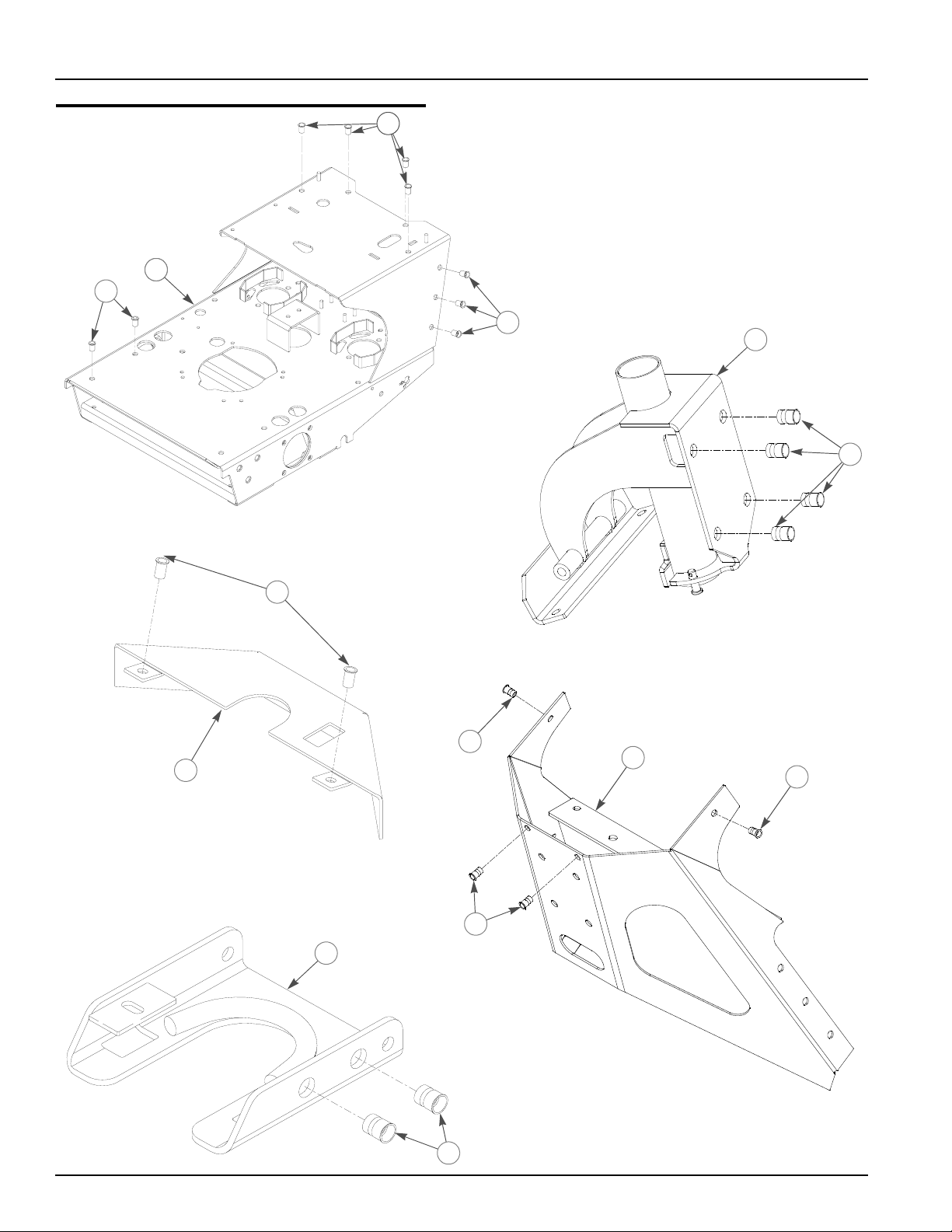
Frame Rivet Nut Installation
2
1
1
3
2
4
2
5
5
6
5
8
7
5
3
2-2 778837 6/06
Page 9

Frame Rivet Nut Installation
INDEX NOSERVICE
PAR T NO.
1 N/A 335273 1 HYDRO WALK BEHIND FRAME
2 N/A 808493 14 NUTSERT, 3/8-16
3 N/A 808485 6 NUTSERT, 5/16-18
4 330498 330498 1 STEERING PIVOT
5 N/A 808477 6 NUTSERT, 1/4-20
6 340182 340182 1 LOWER CONSOLE PANEL
7 340174 340174 1 CONSOLE SUPPORT
8 341693 341693 1 NEUTRAL LOCK
MFG.
PART NO.
QTY DESCRIPTION
NOTES:
778837 6/06 2-3
Page 10
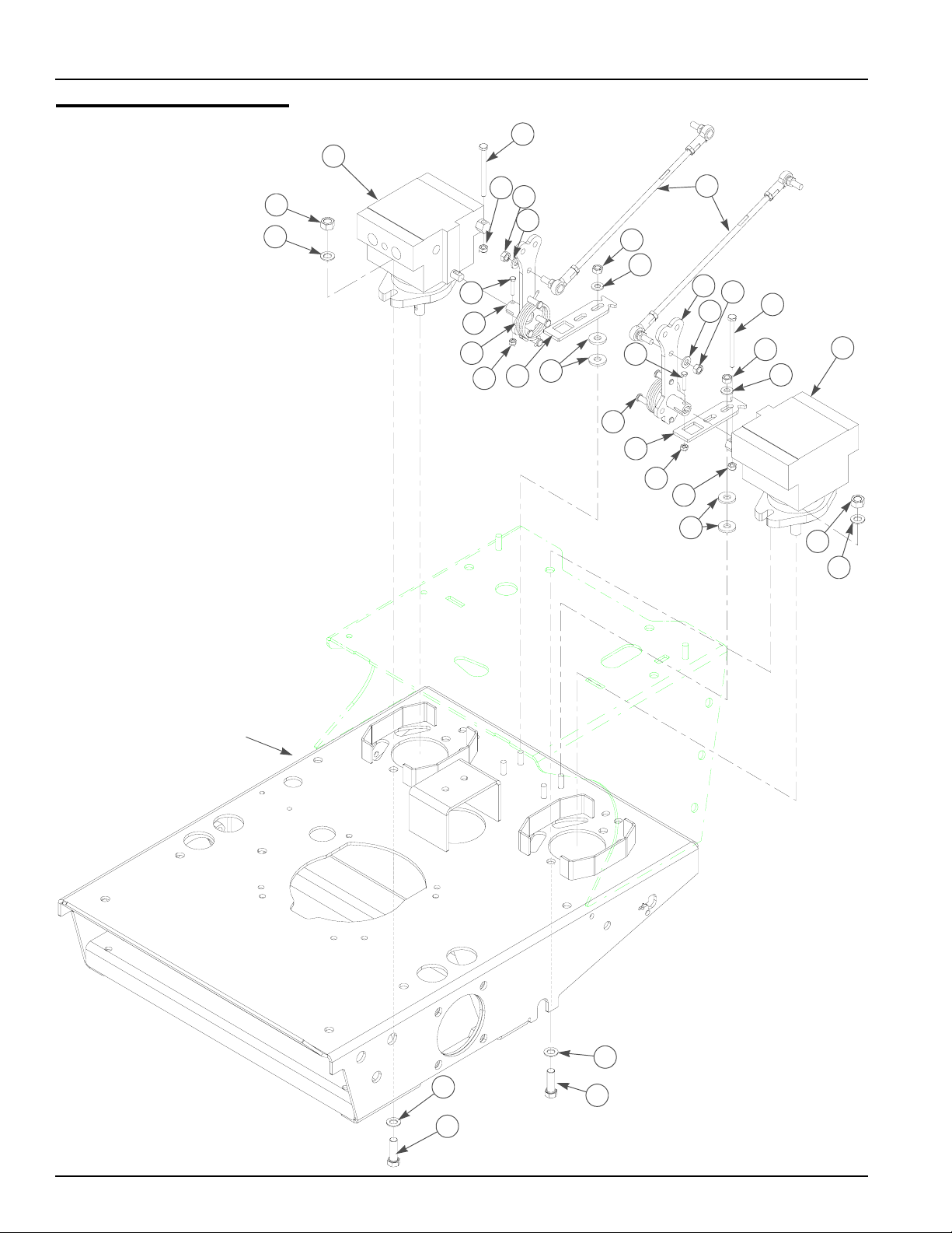
Pump Installation
4
1
6
15
7
12
5
11
4
14
12
1
2
3
6
2
3
9
8
11
12
14
12
7
9
15
13
10
8
13
10
TRACTOR FRAME
3
16
3
16
2-4 778837 6/06
Page 11

Pump Installation
INDEX
NO.
1 768226 768226 2 HYDRO GEAR PUMP BDP10L137P
2 041707 041707 4 NT .437-14 HX G5 ZN
3 704742 704742 8 FW .453X .812X.060 ZN
4 075994 075994 2 CS .250-20X3.250 ZN
5 778514 778514 2 PUMP ROD ASSEMBLY
6 068551 068551 2 NT .250-20 HX NL ZN
7 341289 341289 2 PUMP ARM
8 778621 778621 2 TORSION PUMP SPRING
9 715599 715599 2 CS 10-24X1.000 HX G5 ZN
10 059832 059832 2 NT #10-24 HX NL ZN
11 041152 041152 2 NT .312-24 HX ZN
12 768523 768523 6 FW .343X.687X.051X.080 HD ZN/YL
13 341487 341487 2 NEUTRAL ADJUSTER PLATE
14 034272 034272 4 NT .312-18 HX G5 ZN
15 712919 712919 8 FW .406X 1.00X.12 HRD ZN
16 705186 705186 4 CS .437-14X1.375 HX G5 ZN
SERVICE
PAR T NO.
MFG.
PART NO.
QTY. DESCRIPTION
NOTES:
778837 6/06 2-5
Page 12
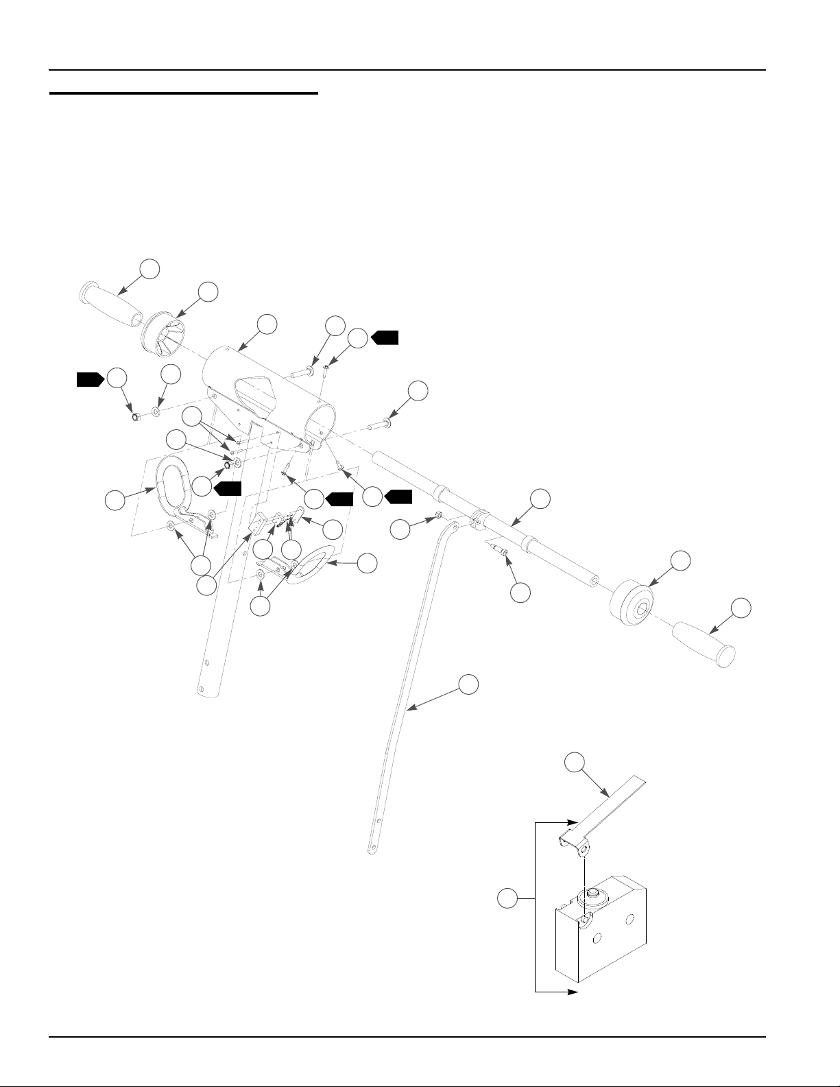
Upper H-Bar Assembly
4
3
1
9
2
11
10
10
8
9
2
14
15
10
13
10
12
16
5
1
12
11
12
1
5
1
6
17
2
3
7
4
18
14
2-6 778837 6/06
Page 13

Upper H-Bar Assembly
ITEM
NO.
1 341446 341446 1 STEERING PIVOT TUBE
2 333047 333047 1 STEERING BAR
3 773556 773556 2 STEERING BEARING
4 771139 771139 2 GRIP, .875 X 4.562 BLACK
5 779157 779157 2 CB .312-18X 1.750 ZN G5
6 068551 068551 1 NT .250-20 HX NL ZN
7 772483 772483 1 SB .312X .750 SH .250-20TD ZN/YL
8 077842 077842 4 MS # 6-32 X1.000 RD SL ZN
9 058776 058776 2 NT .312-18 HX NL ZN
10 768523 768523 6 FW .343X.687X.051/.080 HD ZN/YL
11 341826 341826 2 OPC ARM
12 769299 769299 6 SC #10 X.750 PHILLIPS TYPE AB ZN
13 342378 342378 2 SWITCH SPACER
14 778506 778506 1 OPERATOR PRESENCE WIRE HARNESS
15 779165 779165 4 RP .078X .50 LONG ZN
16 039693 039693 2 WN #6-32 X 1.00 TP 1116
17 341149 341149 1 SPEED BAR
18 794412 N/A 1 HBAR MICRO SWITCH LEVER
SERVICE
PART NO.
MFG PART
NO.
QTY DESCRIPTION
NOTES:
1. Screw will be self tapped into steering handle bearing.
2. Must be tight but must not be so tight as to cause binding of item 2
(333047 Steering Bar) within item 3 (773556 Steering Bearing). Items 11
(341826 OPC Arm) must move freely.
778837 6/06 2-7
Page 14
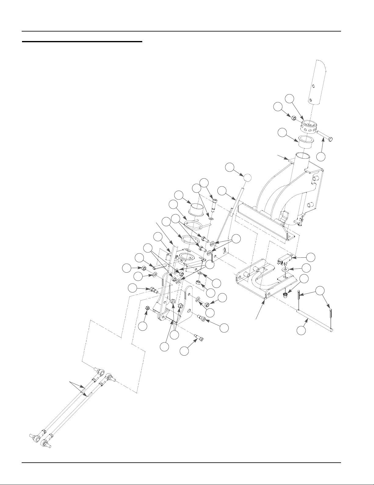
Lower H-Bar Assembly
1
3
4
22
SPEED
BAR
15
13
23
26
STEERING
13
PIVOT
NEUTRAL
LOCK
19
21
6
7
8
4
10
12
11
14
9
16
13
13
5
8
9
22
23
2
17
18
20
PUMP
ROD
ASSEMBLIES
24
25
2-8 778837 6/06
Page 15

Lower H-Bar Assembly
INDEX
NO.
1 332072 332072 1 LOCK COLLAR
2 038828 038828 1 CS .312-18X2.250 HX G5 ZN
3 754317 754317 1 NT .312-18 LOW CROWN ACORN ZN
4 728584 728584 2 PIVOT TUBE BUSHING
5 341651 341651 1 NEUTRAL LOCK HANDLE
6 768499 768499 1 KNOB, 1.00 RDX.312-18 FE BLACK
7 778522 778522 2 SB .375X1.000 SH.312-18TD ZN
8 779173 779173 4 FW .312X .562X .06 SPL HD ZN/YL
9 034272 034272 4 NT .312-18 HX G5 ZN
10 778530 778530 1 TORSION SPRING
11 342857 342857 1 STEERING SPACER
12 034280 034280 2 CS .312-18X .750 HX G5 ZN
13 768523 768523 6 FW .343X.687X.051/.080 HD ZN/YL
14 341743 341743 1 STEERING SUPPORT
15 004416 004416 1 RP .375 X 2.25 ZN
16 765339 765339 2 BUSHING, INGUS#MFI-0608_05
17 726711 726711 1 SWITCH
2
3
18 049346 049346 1 FW .375X .870X.078 ZN
19 726778 726778 1 SWITCH BOOT
20 017251 017251 2 CP .156DX1.000 LG HML ZN
21 341503 341503 1 NEUTRAL LOCK ROD
22 041152 041152 2 NT .312-24 HX ZN
23 754358 754358 2 SB .375X.375 SH .312-18
24 341156 341156 1 SPEED CONTROL YOKE
25 772483 772483 1 SB .312X.750 SH .250-20TD ZN/YL
26 068551 068551 1 NT .250-20 HX NL ZN
SERVICE
PAR T NO.
023002 023002 1 DOUBLE POLE SWITCH
MFG.
PART NO.
QTY DESCRIPTION
NOTES:
1. For H-Bar in lower position, install Item 1 (Lock Collar) and item 14
(Steering Support) in upper holes in (Upper H-Bar Assembly). Install
Speed Bar) using upper hole of the two lower holes in Speed Bar).
2. Used on pull start models only.
3. Used on electric start models only.
778837 6/06 2-9
Page 16
H-Bar Installation
H-BAR
ASSEMBLY
5
CONSOLE
SUPPORT
4
2
1
3
2
2
TRACTOR
FRAME
6
1
2-10 778837 6/06
Page 17

H-Bar Installation
ITEM
NO.
1 036244 036244 9 CS .375-16X1.000 HX G5 ZN
2 767954 767954 13 FW .406X .812 X.060 SAE HD ZN
3 778738 778738 1 WIRING CLAMP
4 054502 054502 1 NT .375-16 HX GRD 5 ZN
5 052860 052860 2 CS .375-16X1.250 HX G5 ZN
6 080655 080655 1 CS .375-16X1.500 HX G5 ZN
SERVICE
PART NO.
MFG.
PART NO.
QTY DESCRIPTION
NOTES:
778837 6/06 2-11
Page 18

2-12 778837 6/06
Page 19

Chapter 3 Contents
Hydraulic Installation—37”. . . . . . . . . . . . . . . . . . . . . . . . . . . . . . . . . 3-2
Hydraulic Installation—48" & 54" . . . . . . . . . . . . . . . . . . . . . . . . . . . . 3-4
Hydraulic Hose Routing . . . . . . . . . . . . . . . . . . . . . . . . . . . . . . . . . . . 3-6
778837 6/06 3-1
Page 20
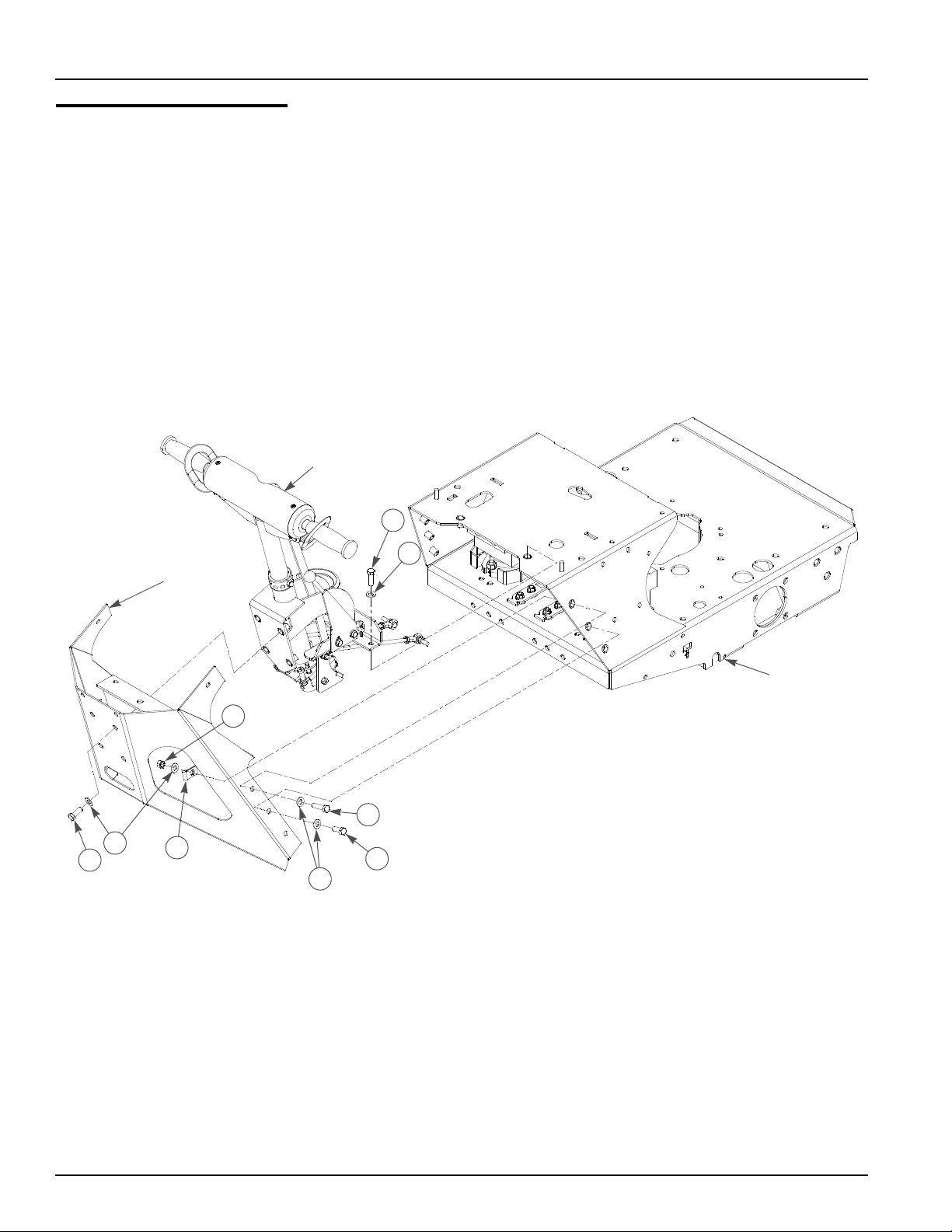
Hydraulic Installation—37"
9
2
1
2
4
3
5
6
7
8
TRACTOR
FRAME
10
13
11
12
17
14
15
16
P/O
WHEEL
MOTOR
18
19
4
3
20
21
3-2 778837 6/06
Page 21

Hydraulic Installation—37"
ITEM
NO.
1 079178 079178 1 CS .250-20X .375 HX G5 ZN
2 768515 768515 3 FW .281X.625X.051/.080 HD ZN/YL
3 342055 342055 1 OIL CAP LOCK ANGLE,
4 032763 032763 1 BREATHER CAP
5 032771 032771 1 STRAINER
6 036244 036244 2 CS .375-16X1.000 HX G5 ZN
7 767954 767954 2 FW .406X .812 X.060 SAE HD ZN
8 340026 340026 1 HYD OIL RESERVOIR
9 055947 055947 2 CS .250-20X .500 HX G5 ZN
10 748681 748681 1 .75X1.35X1.06X.18 GROMMET
11 768333 768333 1 FILTER HEAD
12 768341 768341 1 FILTER ELEMENT
13 779132 N/A 1 FITTING, STR-6MORB/-6JIC
1
14 763953 N/A 1 FITTING T,-6 O-RING/-6JIC/6JIC
1
15 070037 070037 8 FW .530 X 1.06 X .19 HRD ZNYC
16 779959 N/A 4 FITTING, -10MORB/-8MJIC
2
17 779926 779926 2 ROSS WHEEL MOTOR
18 767962 767962 8 FW .531X 1.063X.090 SAE HD ZN
19 008573 008573 8 CS .500-13X2.500 HX G5 ZN
20 782276 782276 2 HUB, 4-ON-4
21 061077 061077 8 LN ZN 1/2-20 DICO 5082
SERVICE
PART NO.
MFG.
PART NO.
QTY DESCRIPTION
NOTES:
1. Items contained in WB Hydraulic Hose and Fitting Kit (778480).
2. Items contained in WB Hydraulic Unique Fittings Kit for Narrow Tractor
(779934).
3. Torque to 70–75 ft.lbs.
4. Torque to 200–225 ft-lbs.
778837 6/06 3-3
Page 22
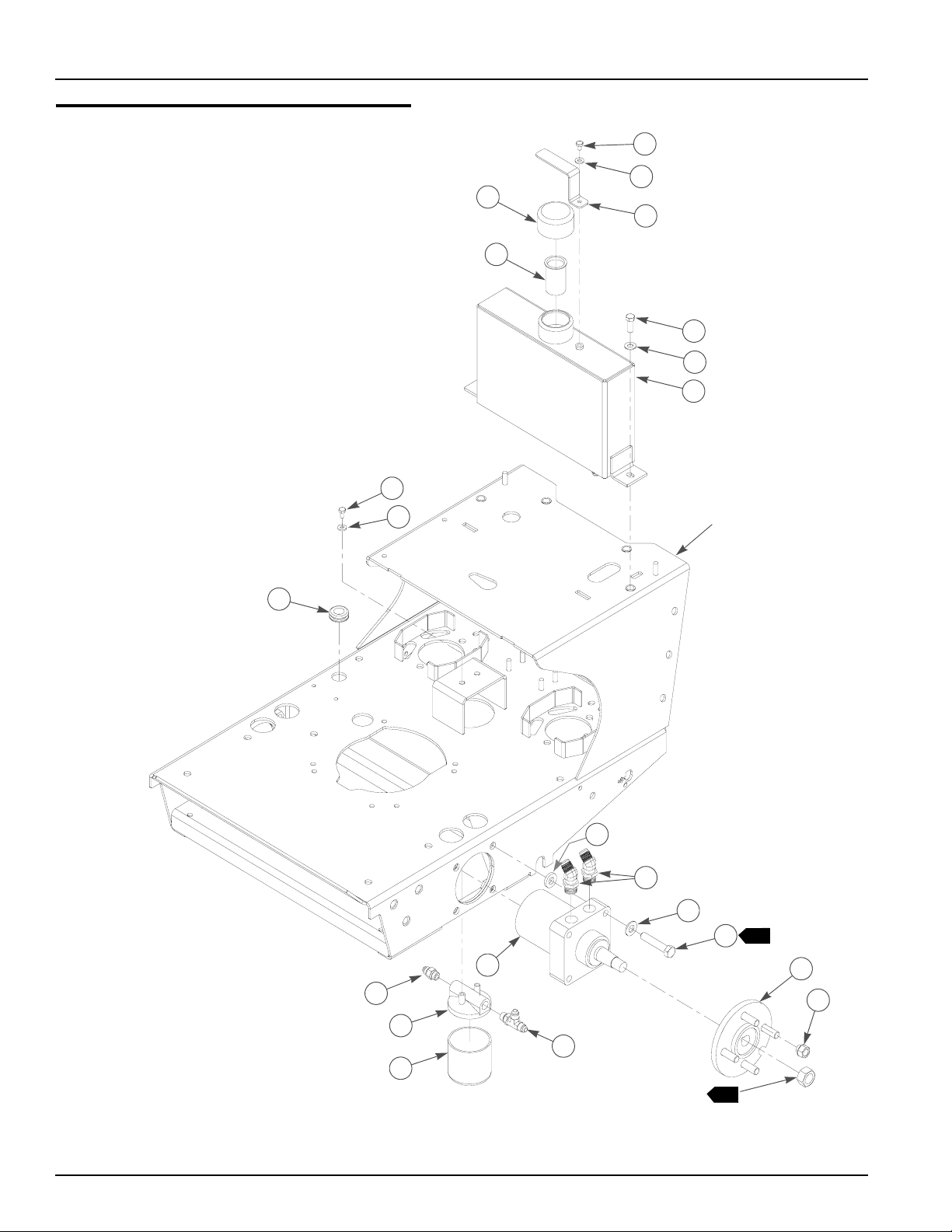
Hydraulic Installation—48" & 54"
4
5
9
2
10
1
2
3
6
7
8
TRACTOR
FRAME
13
11
12
16
15
17
A
14
P/O
WHEEL
4
MOTOR
3-4 778837 6/06
18
19
3
20
21
Page 23

Hydraulic Installation—48" & 54"
ITEM
NO.
1 079178 079178 1 CS .250-20X .375 HX G5 ZN
2 768515 768515 3 FW .281X.625X.051/.080 HD ZN/YL
3 342055 342055 1 OIL CAP LOCK ANGLE,
4 032763 032763 1 BREATHER CAP
5 032771 032771 1 STRAINER
6 036244 036244 2 CS .375-16X1.000 HX G5 ZN
7 767954 767954 2 FW .406X .812 X.060 SAE HD ZN
8 340026 340026 1 HYD OIL RESERVOIR
9 055947 055947 2 CS .250-20X .500 HX G5 ZN
10 748681 748681 1 .75X1.35X1.06X.18 GROMMET
11 768333 768333 1 FILTER HEAD
12 768341 768341 1 FILTER ELEMENT
13 779132 N/A 1 FITTING, STR-6MORB/-6JIC
1
14 763953 N/A 1 FITTING T,-6 O-RING/-6JIC/6JIC
1
15 771311 N/A 4 FITTING, 90-8MORB/-8MJIC
2
16 314674 314674 8 MOTOR MOUNT BUSHING
17 768234 768234 2 ROSS WHEEL MOTOR
18 767962 767962 8 FW .531X 1.063X.090 SAE HD ZN
19 042630 042630 8 CS .500-13X6.50 HX G5 ZN
20 782276 782276 2 HUB, 4-ON-4
21 061077 061077 8 LN ZN 1/2-20 DICO 5082
SERVICE
PART NO.
MFG.
PART NO.
QTY DESCRIPTION
NOTES:
1. Items contained in WB Hydraulic Hose and Fitting Kit (778480).
2. Items contained in WB Unique Fittings Kit for Wide Tractor (779942).
3. Torque to 70–75 ft.lbs.
4. Torque to 200–225 ft-lbs.
778837 6/06 3-5
Page 24
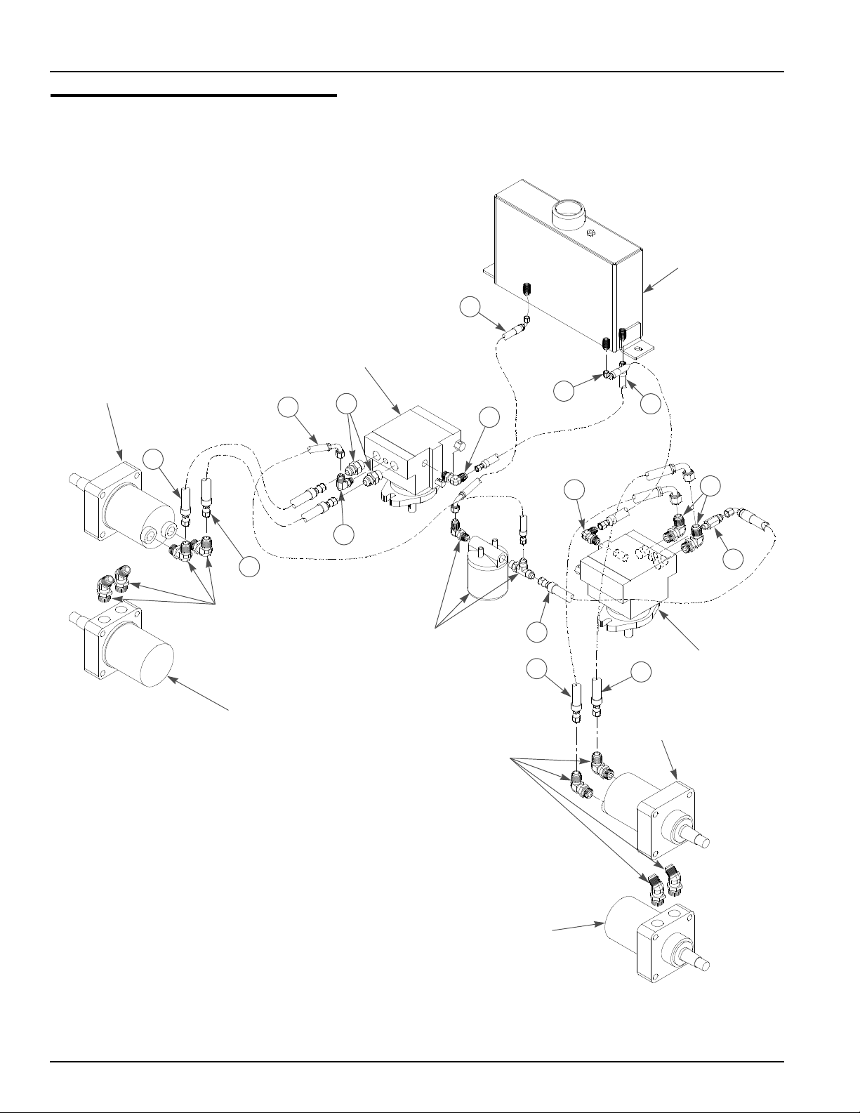
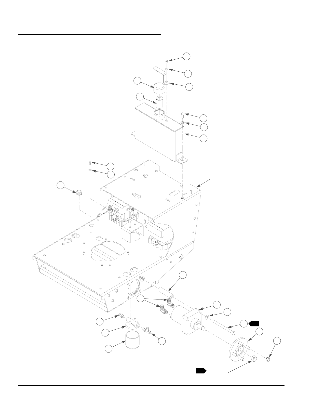
Hydraulic Hose Routing
RIGHT
PUMP
RIGHT WHEEL
MOTOR, 48" (& US 54")
6
4
11
OIL
RESERVOIR
1
3
2
12
5
SEE
HYDRAULIC
INSTALLATION
RIGHT WHEEL
MOTOR , 37"
10
SEE
HYDRAULIC
INSTALLATION
SEE
HYDRAULIC
INSTALLATION
12
9
7
8
LEFT WHEEL
MOTOR, 48" (& US 54")
13
14
LEFT
PUMP
LEFT WHEEL
MOTOR, 37"
3-6 778837 6/06
Page 25

Hydraulic Hose Routing
ITEM
NO.
1 778977 N/A 1 HOSE, -6 90 -6 90, PL 15.00
2 779108 N/A 1 HOSE, -6STR-6STR , PL 18.50
3 779116 N/A 1 HOSE, -6STR -6 90, PL 16.37
4 778936 N/A 1 HOSE, -8STR-8STR 17.00
5 778944 N/A 1 HOSE, -8STR-8STR 15.00
6 778985 N/A 1 HOSE, -6STR -6 90, PL 13.00
7 778951 N/A 1 HOSE, -8STR-8 90 24.75
8 778969 N/A 1 HOSE, -8STR-8 90 22.75
9 778993 N/A 1 HOSE, -6STR -6 90, PL 18.50
10 779124 N/A 1 FITTING, 90-4MORB/-6MJIC
11 771337 N/A 2 FITTING, STR-8MORB/-8MJIC
12 763946 N/A 2 FITTING 90, -6 O-RING/-6 JIC
13 771311 N/A 2 FITTING, 90-8MORB/-8MJIC
14 771303 N/A 1 FITTING, STR-4MORB/-6MJIC
SERVICE
PART NO.
MFG.
PART NO.
QTY DESCRIPTION
NOTES:
1. All items contained in WB Hydraulic Hose and Fitting Kit (778480).
2. Hydraulic system oil capacity 5.3 qts.(10W40).
3. Add 3 oz. of Lubrizol® (027912) to oil reservoir when hydraulic oil is
changed.
778837 6/06 3-7
Page 26

3-8 778837 6/06
Page 27

Chapter 4 Contents
Fuel System. . . . . . . . . . . . . . . . . . . . . . . . . . . . . . . . . . . . . . . . . . . . 4-2
778837 6/06 4-1
Page 28
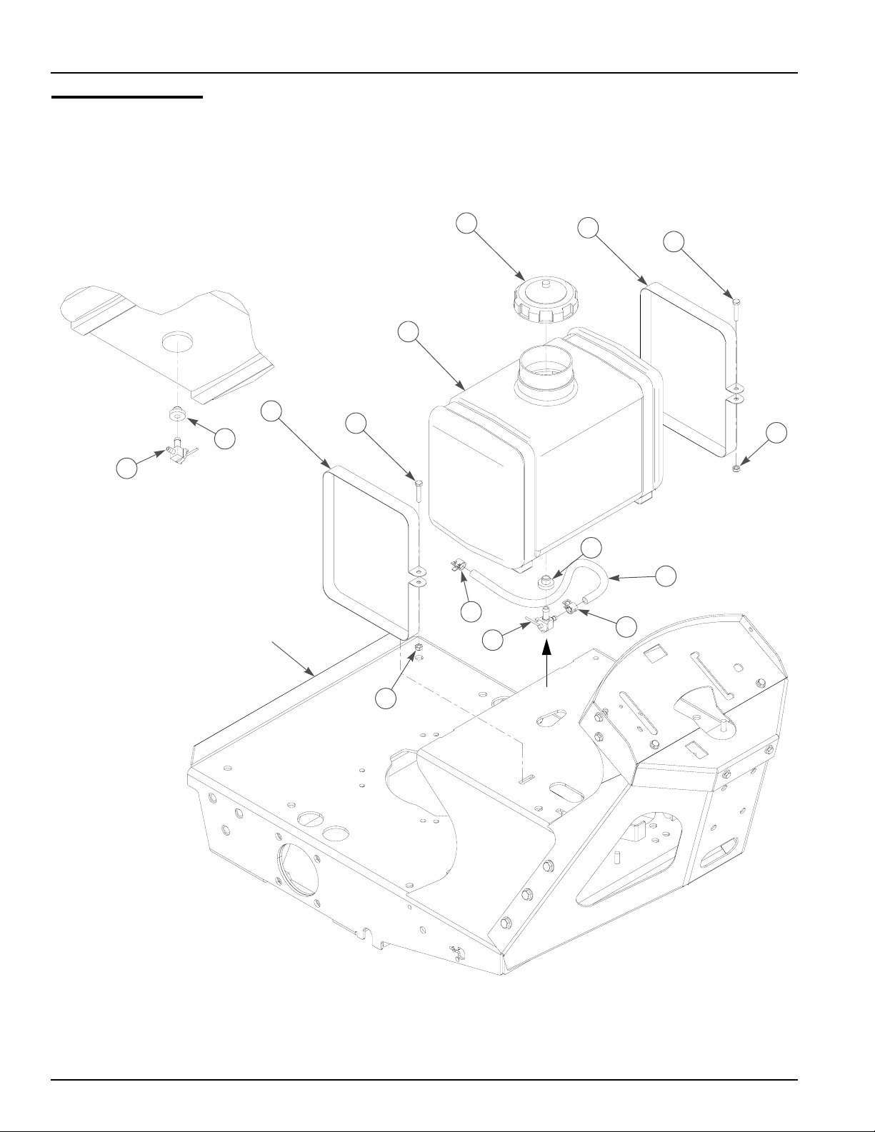
Fuel System
P/O TANK
1
2
3
4
9
VIEW A
ROTATED 180
8
°
TRACTOR
FRAME
3
4
8
7
6
9
5
A
6
5
4-2 778837 6/06
Page 29

Fuel System
ITEM
NO.
1 779306 N/A 1 FUEL CAP
2 775825 775825 1 FUEL TANK
3 339838 339838 2 FUEL TANK MOUNT STRAP
4 704924 704924 2 CS .250-20X1.375 HX G5 ZN
5 068551 068551 2 NT .250-20 HX NL ZN
6 000323 000323 2 HOSE CLIP
7 015818 015818 16” FUEL LINE
1
8 785295 785295 1 FUEL SHUTOFF VALVE GROMMET
9 785287 785287 1 FUEL SHUTOFF VALVE
SERVICE
PART NO.
MFG.
PART NO.
QTY DESCRIPTION
NOTES:
1. Order quantity of 2 ft. as service part.
778837 6/06 4-3
Page 30

4-4 778837 6/06
Page 31

Chapter 5 Contents
Pump Drive Assembly—15 & 17 HP . . . . . . . . . . . . . . . . . . . . . . . . . 5-2
Pump Drive Assembly—23 & 25 HP . . . . . . . . . . . . . . . . . . . . . . . . . 5-4
778837 6/06 5-1
Page 32

Pump Drive Assembly—15 & 17 HP
TRACTOR
FRAME
6
ENGINE
SHAFT
PUMP
SHAFT
24
1
PUMP
SHAFT
2
3
4
2
5
2
5
4
29
30
28
27
31
29
26
26
18
18
25
22
23
33
19
20
1
21
8
9
12
13
17
14
15
13
16
3
10
3
9
11
32
7
5-2 778837 6/06
Page 33

Pump Drive Assembly—15 & 17 HP
ITEM
NO.
1 768127 768127 2 KEY 5MM X30MM RADIUS ENDS
2 008193 008193 1 NT .500-13 HX G5 ZN
3 767962 767962 2 FW .531X 1.063X.090 SAE HD ZN
4 325308 325308 2 PULLEY & FAN
5 083196 083196 4 SS .312-18 X .750 SQ-HD ZN
4
6 748681 748681 1 .75X1.35X1.06X.18 GROMMET
7 776435 776435 1 PUMP DRIVE BELT
8 016428 016428 1 CS .375-16X2.50 HX GR5 ZN
9 767954 767954 2 FW .406X .812 X.060 SAE HD ZN
10 036384 036384 1 SPRING 1/4 COIL PL
11 046763 046763 1 NT .375-16 FLEX-LOK ZN
12 056077 056077 1 CS .250-20X1.000 HX G5 ZN
13 768515 768515 2 FW .281X.625X.051/.080 HD ZN/YL
14 259812 259812 1 DECK LIFT SPRING CHAIN
15 778746 778746 1 2" SPLIT RING
16 068551 068551 1 NT .250-20 HX NL ZN
17 340042 340042 1 HYDRAULIC PUMP IDLER ARM
18 770867 770867 2 PLASTIC BUSHING
19 340158 340158 1 IDLER PIVOT BUSHING
20 077859 077859 1 CS .500-13X3.250 HX G5 ZN
21 776484 776484 1 CLUTCH
22 763417 763417 1 FW .454X1.50X.250
23 778217 778217 1 CS .437-20X2.250 G5 Z
24 340885 340885 1 PUMP IDLER CHAIN
25 779272 779272 1 TINNERMAN CLIP
26 212076 212076 2 1/4 SQ X 1.50 LONG KEY
27 778357 778357 1 PUMPDRIVE PULLEY (5”)
28 064014 064017 1 CS .312-18X .875 HX G5 ZN
29 768523 768523 2 FW .343X.687X.051/.080 HD ZN/YL
30 349738 349738 1 CLUTCH MOUNT
31 778738 778738 1 .312 WIRING CLAMP
32 058776 058776 1 NT .312-18 HX NL ZN
33 768689 768689 1 IDLER PULLEY
SERVICE
PART NO.
030601 N/A 4 SS .312-18X .500 SH NL
MFG.
PART NO.
QTY DESCRIPTION
NOTES:
1. Torque to 45–48 ft-lbs.
2. Torque to 12–15 ft-lbs.
3. Tension Idler Arm Spring to length = 4.5-5".
4. Used on tractors with serial number 01082125 and higher.
Note: New clutches are to be burnished. After installing a new clutch, its important to burnish the
clutch to insure maximum deck clutch life, in a open area with no by standers, set the
engine speed to half throttle. Cycle the deck clutch on for 15 seconds, and then off for 15
seconds. Repeat this operation 10 times, it will require about 5 minutes to complete.
778837 6/06 5-3
Page 34

Pump Drive Assembly (23 & 25HP)
PUMP
SHAFT
TRACTOR
FRAME
ENGINE
SHAFT
3
PUMP
SHAFT
1
2
34
15
4
5
6
7
13
14
4
5
16
36
11
12
17
19
3
18
19
21
2
33
2
1
35
26
29
10
9
22
8
2
9
8
10
23
25
24
30
20
27
28
30
25
31
3
32
5-4 778837 6/06
Page 35

Pump Drive Assembly—23 & 25HP
ITEM
NO.
1 008193 008193 1 NT .500-13 HX G5 ZN
2 767962 767962 2 FW .531X 1.063X.090 SAE HD ZN
3 036236 036236 2 CS .312-18 X 1.00 HX G5 ZNYC
4 768523 768523 4 FW .343X.687X.051/.080 HD ZN/YL
5 778738 778738 2 .312 WIRING CLAMP
6 029876 N/A 4 LW .312 INT-EXT TOOTH ZNYC
7 052837 N/A 3 CS .312-18X1.500 HX G5 ZNYC
8 325308 325308 2 PULLEY & FAN
9 083196 083196 4 SS .312-18 X .750 SQ-HD ZN
10 768127 768127 2 KEY 5MM X30MM RADIUS ENDS
11 788356 788356 1 ENGINE A-SEC PULLEY
12 712372 712372 1 KEY 1/4 SQ X 0.66 LONG
13 787366 787366 1 WARNER Z CLUTCH
14 784918 784918 1 RUBBER BUMPER
15 379594 379594 1 WARNER CLUTCH ANCHOR
16 034272 034272 2 NT .312-18 HX G5 ZNYC
17 763417 763417 1 FW .454X1.50X.250
18 754101 754101 1 CS .437-20 X 1.25 G5 ZNYC
19 770867 770867 2 PLASTIC BUSHING
20 340042 340042 1 HYDRAULIC PUMP IDLER ARM
21 340158 340158 1 IDLER PIVOT BUSHING
22 077859 077859 1 CS .500-13X3.250 HX G5 ZN
23 016428 016428 1 CS .375-16X2.50 HX GR5 ZN
24 056077 056077 1 CS .250-20X1.000 HX G5 ZN
25 767954 767954 2 FW .406X .812 X.060 SAE HD ZN
26 768689 768689 1 IDLER PULLEY
27 259812 259812 1 DECK LIFT SPRING CHAIN
28 778746 778746 1 2" SPLIT RING
29 036384 036384 1 SPRING 1/4 COIL PL
30 768515 768515 2 FW .281X.625X.051/.080 HD ZN/YL
31 068551 068551 1 NT .250-20 HX NL ZN
32 046763 046763 1 NT .375-16 FLEX-LOK ZN
33 776435 776435 1 PUMP DRIVE BELT
34 340885 340885 1 PUMP IDLER CHAIN
35 779272 779272 1 TINNERMAN CLIP
36 791251 791251 1 CLUTCH PIGTAIL HARNESS WITH DIODE
SERVICE
PART NO.
MFG.
PART NO.
QTY DESCRIPTION
NOTES:
1. Torque to 45–48 ft-lbs.
2. Torque to 12–15 ft-lbs.
3. Tension Idler Arm Spring to length = 4.5–5”.
778837 6/06 5-5
Page 36

5-6 778837 6/06
Page 37

Chapter 6 Contents
Console Assembly . . . . . . . . . . . . . . . . . . . . . . . . . . . . . . . . . . . . . . . 6-2
778837 6/06 6-1
Page 38

Console Assembly
5
4
1
3
2
CONSOLE
SUPPORT
1
LOWER
CONSOLE
PANEL
7
11
2
5
9
11
12
10
8
6
6
8
6-2 778837 6/06
Page 39

Console Assembly
ITEM
NO.
1 340208 340208 1 UPPER CONSOLE PANEL
2 776518 776518 1 KEY SWITCH
2
2 045898 045898 1 IGNITION SWITCH
3
3 083022 N/A 1 IGNITION KEY
4 778241 778241 1 D. C. QUARTZ HOUR METER
5 786657 786657 1 CHOKE CABLE
4
6 768515 768515 6 FW .281X.625X.051/.080 HD ZN/YL
7 073122 073122 2 CS 10-24X1.000 HXWH ZN
8 056077 056077 6 CS .250-20X1.000 HX G5 ZN
9 776476 776746 1 PTO SWITCH
10 778365 778365 1 THROTTLE/CHOKE CABLE
11 704932 704932 4 FW .219X .500X.048 ZN
12 035626 035626 2 NT #10-24 HX SZN
SERVICE
PART NO.
785808 785808 1 INDAK COATED KEY
MFG PART
NO.
QTY DESCRIPTION
NOTES:
1. Included with Item 2 (776518 Key Switch and 045898 Ignition Switch).
2. Pull start models only.
3. Electric start models only.
4. Used on mowers with 23 and 25 HP engines only.
778837 6/06 6-3
Page 40

6-4 778837 6/06
Page 41

Chapter 7 Contents
Engine Installation—Recoil Start . . . . . . . . . . . . . . . . . . . . . . . . . . . . 7-2
Engine Installation—Electric Start . . . . . . . . . . . . . . . . . . . . . . . . . . . 7-4
Engine Installation—23 & 25 HP . . . . . . . . . . . . . . . . . . . . . . . . . . . . 7-6
Battery Installation—Electric Start . . . . . . . . . . . . . . . . . . . . . . . . . . 7-10
778837 6/06 7-1
Page 42

Engine Installation—Recoil Start
1
2
3
TRACTOR
FRAME
10
4
5
6
8
9
8
7
2
3
12
GROUND
WIRE
TRACTOR
FRAME
8
11
7-2 778837 6/06
Page 43

Engine Installation—Recoil Start
ITEM
NO.
1 776419 776419 1 KAWASAKI 15 HP ENGINE, RECOIL
2 034272 034272 5 NT .312-18 HX G5 ZN
3 768523 768523 6 FW .343X.687X.051/.080 HD ZN/YL
4 780775 780775 1 KAWASAKI OIL DRAIN ADAPTER O-RING
5 780767 780767 1 KAWASAKI OIL DRAIN ADAPTER
6 771378 771378 1 PUSHLOC 16.00 HYDRO HOSE
7 035329 035329 1 3/8 NPT PIPE PLUG
8 029876 029876 4 LW .312 INT-EXT TOOTH ZN
9 052837 082837 3 CS .312-18X1.500 HX G5 ZN
10 778738 778738 1 .312 WIRING CLAMP
11 064345 064345 1 CS .312-18X2.000 HX G5 ZN
12 778498 778498 1 WALKBEHIND WIRE HARNESS
SERVICE
PART NO.
776427 776427 1 KAWASAKI 17HP ENGINE, RECOIL
MFG.
PART NO.
1. Engine oil capacity 1 qt.
2. Engine speed 3600±50 RPM.
QTY DESCRIPTION
NOTES:
778837 6/06 7-3
Page 44

Engine Installation—Electric Start
1
2
3
5
76
4
1
BLK
NEG BATTERY
CABLE
TO BULLET
TERMINALS
1
18
2
3
3
2
3
13
12
12
13
14
19
15
TO BLADE
TERMINAL
RED/BLK
17
16
1
1
12
TRACTOR
8
8
9
10
FRAME
13
8
11
POS BATTERY
CABLE
1
12
13
PUR
7-4 778837 6/06
Page 45

Engine Installation—Electric Start
INDEX
NO.
1 777813 777813 1 KAWASAKI 17 HP 3600 RPM ENGINE
2 034272 034272 5 NT .312-18 HX G5 ZN
3 768523 768523 6 FW .343X.687X.051/.080HDZN/YL
4 780775 780775 1 KAWASAKI OIL DRAIN ADAPTER O-RING
5 780767 780767 1 KAWASAKI OIL DRAIN ADAPTER
6 771378 771378 1 PUSHLOC 16.00 HYDRO HOSE
7 035329 035329 1 3/8 NPT PIPE PLUG
8 029876 029876 4 LW .312 INT-EXT TOOTH ZN
9 778738 778738 1 WIRING CLAMP .312
10 052837 052837 3 CS .312-18X1.500 HX G5 ZN
11 064345 064345 1 CS .312-18X2.000 HX G5 ZN
12 017079 017079 5 FW .250X .560X.04 SAE ZN
13 024927 024927 5 NT .250-20 HX GR.5 ZN
14 768820 768820 1 BATTERY CABLE
15 044255 044255 1 NT #10-32 HX ZN
16 030817 030817 1 STARTER SOLENOID
17 016147 016147 2 CS .250-20X .750 HXFLK ZN
18 779991 779991 1 ES WB WIRE HARNESS
19 792192 792192 1 STARTER RELAY GROUND WIRE
SERVICE
PART NO.
MFG.
PART NO.
QTY. DESCRIPTION
NOTES:
1. Black, Purple and Red/Blk wires are part of item 18 (779991 Wire
Harness).
2. Engine oil capacity 1 qt.
3. Engine speed 3600±50 RPM.
778837 6/06 7-5
Page 46

Engine Installation—23 & 25 HP
1
3
4
2
8
5
4
9
1
6
7
4
13
14
15
16
12
11
9
10
12
8
9
17
18
2
19
22
21
20
6
35
25
TO BULLET
TERMINALS
3
27
8
BLK
9
9
7
3
9
23
24
23
34
22
25
20
21
TO BLADE
33
TERMINAL
17
18
19
29
30
3
2
8
37
31
3
26
28
23
24
23
36
PUR
RED/BLK
32
3
7-6 778837 6/06
Page 47

Engine Installation—23 & 25 HP
INDEX
NO.
1 777656 777656 1 KAWASAKI 23HP 3600 RPM ENGINE (USED ON 927129 ONLY)
2 785741 785741 1 MOUNTING BAND
3 786673 786673 1 DONALDSON AIR CLEANER CAP
4 057661 057661 2 HOSE CLAMP
1
5 788943 788943 1 AIR FILTER INDICATOR
6 782763 782763 1 AIR CLEANER
7 788406 788406 1 REMOTE AIR FILTER HOSE
8 034272 034272 7 NT .312-18 HX G5 ZNYC
9 768523 768523 12 FW .343X.687X.051/.080HDZN/YL
10 036236 036236 2 CS .312-18 X 1.00 HX G5 ZNYC
11 379669 379669 1 AIR CLEANER MOUNT BRACKET
12 720177 720177 4 CS M8-1.25 X 20 10.9 HXFLZNYC
4
13 780775 780775 1 KAWASAKI OIL DRAIN ADAPTER O-RING
14 780767 780767 1 KAWASAKI OIL DRAIN ADAPTER
15 771378 771378 1 PUSHLOC 16.00 HYDRO HOSE
16 035329 035329 1 3/8 NPT PIPE PLUG
17 022053 022053 2 EXHAUST MUFFLER
18 073189 073189 2 MUFFLER CLAMP
19 788422 788422 2 KAW 23-25 WALK BEHIND MANIFOLD
20 782664 782664 4 NT M8-1.25 HX STAINLESS STEEL
21 017004 017004 4 LW .312 MED SPRING ZNYC
22 780841 780841 2 MUFFLER GASKET
23 017079 017079 5 FW .250X .560X.04 SAE ZN
24 024927 024927 5 NT .250-20 HX GR.5 ZN
25 768820 768820 1 BATTERY CABLE
26 029876 029876 4 LW .312 INT-EXT TOOTH ZN
27 052837 052837 3 CS .312-18X1.500 HX G5 ZN
28 064345 064345 1 CS .312-18X2.000 HX G5 ZN
29 380840 380840 1 HEAT SHIELD
30 064014 064014 2 CS .312-18 X .875 HX G5 ZNYC
31 016147 016147 2 CS .250-20X .750 HXFLK ZN
32 030817 030817 1 STARTER SOLENOID
33 779991 779991 1 ES WB WIRE HARNESS
34 360693 360693 1 HEAT SHIELD
35 778738 778738 1 WIRING CLAMP .312
36 044255 044255 1 NT #10-32 HX ZN
37 792192 792192 1 STARTER RELAY GROUND WIRE
SERVICE
PART NO.
782318 782318 1 KAWASAKI 25HP 3600 RPM ENGINE (USED ON 927137 ONLY)
MFG.
PART NO.
QTY. DESCRIPTION
778837 6/06 7-7
Page 48

NOTES:
1. Includes one (1) of Item 4 (057661 Hose Clamp).
2. Includes mounting hardware.
3. Part of Item 33 (779991 Wire Harness).
4. Three of item 12 are existing hardware (supplied with engine).
5. Engine oil capacity 2 qt. Engine speed 3600±50 RPM.
7-8 778837 6/06
Page 49

This page intentionally left blank.
778837 6/06 7-9
Page 50

Battery Installation—Electric Start
8
4
1
2
3
4
5
7
6
5
5
5
1
13
TRACTOR
FRAME
10
14
1
11
10
10
12
9
9
10
14
7-10 778837 6/06
Page 51

Battery Installation—Electric Start
INDEX
NO.
1 056077 056077 4 CS .250-20X1.000 HX G5 ZN
2 768515 768515 2 FW .281X.625X.051/.080 HD ZN/YL
3 745166 745166 1 BATTERY HOLD DOWN COVER
4 024927 024927 2 NT .250-20 HX GR.5 ZN
5 029868 029868 4 LW .250 INT-EXT TOOTH ZN
6 780015 780015 1 BATTERY CABLE, (-)
7 771428 771428 1 RED BATTERY CABLE BOOT
8 780007 780007 1 BATTERY CABLE, (+)
9 036236 036236 3 CS .312-18X1.000 HX G5 ZN
10 768523 768523 6 FW .343X.687X.051/.080 HD ZN/YL
11 N/A 808477 2 NUTSERT, 1/4-20 THREAD
12 345413 345413 1 BATTERY BOX
13 740696 740696 1 BATTERY
14 034272 034272 3 NT .312-18 HX G5 ZN
SERVICE
PART NO.
MFG.
PART NO.
QTY DESCRIPTION
NOTES:
778837 6/06 7-11
Page 52

7-12 778837 6/06
Page 53

Chapter 8 Contents
Electrical Schematic—Recoil Start—778498. . . . . . . . . . . . . . . . . . . 8-2
Electrical Schematic—Electric Start—779991. . . . . . . . . . . . . . . . . . 8-4
778837 6/06 8-1
Page 54

Electrical Schematic—Recoil Start—778498
MAIN WIRE HARNESS 778498
16 BLK
IGNITION
SWITCH
776518
16 BLK
16 BLK/WHT
GROUND TO
ENGINE MOUNT
BOLT
PTO SWITCH
1
CLUTCH
776484
16 BLK
BLK
BLK
HOUR METER
778241
16 BLK
16 PUR
16 ORG
16 ORG
3
RED
BLK
776476
16 BLK/YEL
16 BLK/WHT
16 BLK/WHT
NEUTRAL LOCK
SWITCH 726711
16 BLK/YEL
ENGINE
15 HP
776419
17HP
776427
OPERATOR PRESENCE
WIRE HARNESS 778506
16 BLK
16 BLU
OP SWITCH
2
16 BLK
16 BLU
OP SWITCH
8-2 778837 6/06
Page 55

Electrical Schematic—Recoil Start—778498
NOTES:
1. Ignition Switch circuits made:
POSITION CIRCUIT MADE
OFF M+G
ON NONE
2. Operator presence switches close when NO operator present.
3. Neutral Switch opens when in neutral.
778837 6/06 8-3
Page 56

Electrical Schematic—Electric Start—779991
MAIN WIRE HARNESS 779991
16 RED/BLK
14 RED
1
S
M
G
L
16 BLK/WHT
GROUND TO
ENGINE MOUNT
BOLT
IGNITION
SWITCH
045868
B
16 BLK
16 BLK
16 BLK
16 BLK
16 ORG
16 BLK/WHT
BLK
BLK
CLUTCH
776484
16 BLK/WHT
16 ORG
16 PUR
HOUR METER
778241
16 ORG
BLK
GRN
16 ORG
RECTIFIER
16 BLK/YEL
3
NEUTRAL LOCK
SWITCH 023002
ENGINE
17 HP
777813
PTO SWITCH
776476
16 BLK/WHT
16 BLK/YEL
OPERATOR PRESENCE
WIRE HARNESS 778506
OP SWITCH
2
OP SWITCH
16 BLK
16 BLK
16 RED/BLK
16 BLU
16 BLU
BATTERY
740696
GROUND TO
ENGINE MOUNT
BOLT
14 RED
STARTER
16 RED/BLK
4 RED
780007
MOTOR
4 BLK
768820
14 PUR
8-4 778837 6/06
Page 57

Electrical Schematic—Electric Start—779991
NOTES:
1. Ignition Switch circuits made:
POSITION CIRCUIT MADE
OFF M+G
ON B+L
START B+L+S
2. Operator presence switches close when NO operator present.
3. Neutral Switch opens when in neutral.
778837 6/06 8-5
Page 58

8-6 778837 6/06
Page 59

Chapter 9 Contents
Deck Carrier Frame Installation. . . . . . . . . . . . . . . . . . . . . . . . . . . . . 9-2
778837 6/06 9-1
Page 60

Deck Carrier Frame Installation
DECK
CARRIER
FRAME
TRACTOR
FRAME
2
11
9-2 778837 6/06
Page 61

Deck Carrier Frame Installation
ITEM
NO.
1 016527 016527 6 CS .500-13X1.00 HX G5 ZN
2 767962 767962 6 FW .531X 1.063X.090 SAE HD ZN
1. Torque to 75 ft-lbs.
SERVICE
PART NO.
MFG.
PART NO.
QTY DESCRIPTION
NOTES:
778837 6/06 9-3
Page 62

9-4 778837 6/06
Page 63

Chapter 10 Contents
Deck Carrier Assembly . . . . . . . . . . . . . . . . . . . . . . . . . . . . . . . . . . 10-2
37" Deck Assembly . . . . . . . . . . . . . . . . . . . . . . . . . . . . . . . . . . . . . 10-4
37" Deck Pulley Assembly. . . . . . . . . . . . . . . . . . . . . . . . . . . . . . . . 10-6
48" Deck Assembly . . . . . . . . . . . . . . . . . . . . . . . . . . . . . . . . . . . . . 10-8
48" Deck Pulley Assembly. . . . . . . . . . . . . . . . . . . . . . . . . . . . . . . 10-10
54" Deck Assembly . . . . . . . . . . . . . . . . . . . . . . . . . . . . . . . . . . . . 10-12
54" Deck Pulley Assembly. . . . . . . . . . . . . . . . . . . . . . . . . . . . . . . 10-14
37" Deck Cover . . . . . . . . . . . . . . . . . . . . . . . . . . . . . . . . . . . . . . . 10-16
48" Deck Cover . . . . . . . . . . . . . . . . . . . . . . . . . . . . . . . . . . . . . . . 10-17
54" Deck Covers. . . . . . . . . . . . . . . . . . . . . . . . . . . . . . . . . . . . . . 10-18
778837 6/06 10-1
Page 64

Deck Carrier Assembly
17
11
12
17
3
17
3
1
4
17
2
9
6
10
2
3
12
11
13
13
1
14
2
3
5
6
7
8
12
4
5
6
7
1
8
6
15
2
9
10
12
16
25
MOWER
DECK
24
54" DECK SHOWN
37" & 48" DECKS, SIMILAR
23
15
22
21
20
18
19
25
16
21
24
22
20
18
19
23
10-2 778837 6/06
Page 65

Deck Carrier Assembly
ITEM
NO.
1 346130 346130 1 37" WALK BEHIND CARRIER FRAME
2 778399 778399 8 FW .781X 1.375X.250 ZN
3 778373 778373 4 PLASTIC BUSHING
4 705954 705954 2 CS .500-13X1.25 HX G5 ZN
5 344267 344267 2 FW .510X 2.15X.187 SPL ZN
6 072272 072272 8 FW 1.06X 2.00X.134 SAE ZN
7 082180 082180 2 MB 1.000X1.500X.049 PN
8 077123 077123 4 BEARING W/O COLLAR
9 778449 778449 2 BEARING SPACER
10 339689 339689 2 CASTER FORK
11 042630 042630 2 CS .500-13X6.50 HX G5 ZN
12 004168 004168 4 FW .50 X 1.06X.090 SAE ZN
13 017046 017046 2 LW .500 MED SPRING ZN
14 067918 067918 2 NT .500-13 HX G8 ZN
15 768044 768044 2 TIRE/WHEEL ASSEMBLY
16 306969 306969 2 GAGE WHEEL SPACER
17 025593 025593 4 HP .177X3.25 WW#206 ZN
18 706176 706176 2 NT .375-24 HX JAM ZN G5
19 778431 778431 2 SPHERICAL.375-24 MALE ROD END
20 335398 335398 2 REAR DECK HEIGHT ROD
21 054502 054502 2 NT .375-16 HX GRD 5 ZN
22 767954 767954 4 FW .406X .812 X.060 SAE HD ZN
23 005116 005116 2 CS .375-16X1.375 HX G5 ZN
24 758631 758631 2 RP .250X 1.375 HD SPIROL
25 335364 335364 2 FRONT DECK HEIGHT ROD
SERVICE
PART NO.
339671 339671 1 48" WALK BEHIND CARRIER FRAME
343335 343335 1 54" WALK BEHIND CARRIER FRAME
MFG PART
NO.
QTY DESCRIPTION
NOTES:
1. Assemble with extended inner race down.
778837 6/06 10-3
Page 66

37" Deck Assembly
1
3
4
3
5
3
14
2
10
2
5
3
6
5
3
13
9
7
8
11
12
8
7
9
3
5
10
11
10-4 778837 6/06
Page 67

37" Deck Assembly
ITEM
NO.
1 347971 347971 1 DISCHARGE CHUTE
2 005116 005116 2 CS .375-16X1.375 HX G5
3 767954 767954 8 FW .406 X .812 X .060 SAE HD ZN
4 086660 086660 2 NT .375-16 HX LK NY
5 054502 054502 4 NT .375-16 HX GRD 5 ZN
6 317073 317073 1 DISCHARGE CHUTE MOUNT BRKT
7 053199 N/A 2 NT .500-13 HX JAM ZNYC
8 767962 N/A 4 FW .531 X 1.063 X .090 SAE HD ZN
9 781567 781567 2 NT .50-13 HX LK NY
10 031997 N/A 2 ANTI-SCALP WHEEL
11 781708 N/A 2 CS .500-13 X 4.25 HX G5 ZNYC
12 316992 316992 1 BAFFLE
13 332536 332536 1 37" DECK W/A
14 011320 011320 1 CB .375-16X .750 STD ZN
1
SERVICE
PART NO.
788166 788166 1 ANTI SCALP WHEEL ASSY
MFG PART
1. Includes items 7, 8, 10, and 11.
NO.
QTY DESCRIPTION
NOTES:
778837 6/06 10-5
Page 68

37" Deck Pulley Assembly
23
1
3
4
1
9
11
24
10
2
22
2
5
6
7
8
21
37" DECK
GUIDE ORIENTATION
IDLER ARM
GUIDE
3.5±.25
15
13
12
1
7
7
19
14
20
8
16
18
10-6 778837 6/06
17
1
Page 69

37" Deck Pulley Assembly
ITEM
NO.
1 779694 779694 1 37" DECK BELT
2 767954 767954 4 FW .406X .812 X.060 SAE HD ZN
3 016410 016410 1 CS .375-16X2.00 G5 ZN
4 345355 345355 1 DECK IDLER GUIDE
5 504480 504480 1 IDLER PULLEY
6 008193 008193 1 NT .500-13 HX G5 ZN
7 767962 767962 10 FW .531X 1.063X.090 SAE HD ZN
8 770867 770867 2 PLASTIC BUSHING
9 078378 078378 2 CS .500-20X1.500 HX G5 ZN
10 078386 078386 2 FW .510X 1.750X.18 ZN
11 770842 770842 2 DECK DRIVE PULLEY
12 016527 016527 8 CS .500-13X1.00 HX G5 ZN
13 520627 426296 2 SPINDLE HOUSING ASSEMBLY
14 212472 212472 4 KEY 1/4 SQ X 1.00 LONG
15 035808 035808 2 BLADE SADDLE
16 770339 770339 2 19" CLOCKWISE ROTATION BLADE
17 753798 753798 2 CS .500-20X1.75 HX G5 ZN
18 752386 752386 2 CW .515X 2.25X .204 ZN
19 077859 077859 1 CS .500-13X3.250 HX G5 ZN
20 335380 335380 1 IDLER ARM
21 340158 340158 1 IDLER PIVOT BUSHING
22 779272 779272 2 TINNERMAN CLIP
23 259812 259812 1 DECK LIFT SPRING CHAIN
24 036384 036384 1 SPRING
SERVICE
PAR T NO.
MFG PART
NO.
QTY DESCRIPTION
1. Torque to 65–75 ft-lbs.
NOTES:
778837 6/06 10-7
Page 70

48" Deck Assembly
11
1
3
3
11
10
8
7
2
5
3
10
9
2
5
3
4
6
5
3
13
8
12
7
9
10
7
9
8
RIGHT
11
14
7
8
10
11
BLADE
WRAPPER
3
BAFFLE
5
10-8 778837 6/06
Page 71

48" Deck Assembly
ITEM
NO.
1 347971 347971 1 DISCHARGE CHUTE
2 005116 005116 2 CS .375-16X1.375 HX G5
3 767954 767954 8 FW .406 X .812 X .060 SAE HD ZN
4 086660 086660 2 NT .375-16 HX LK NY
5 054502 054502 4 NT .375-16 HX GRD 5 ZN
6 317073 317073 1 DISCHARGE CHUTE MOUNT BRKT
7 053199 N/A 4 NT .500-13 HX JAM ZNYC
8 767962 N/A 8 FW .531X 1.063X.090 SAE HD ZN
9 781567 781567 4 NT .50-13 HX LK NY
10 031997 N/A 4 ANTI-SCALP WHEEL
11 781708 N/A 4 CS .500-13 X 4.25 HX G5 ZNYC
12 316992 316992 1 BAFFLE
13 335745 335745 1 48" DECK W/A
14 011320 011320 1 CB .375-16X .750 STD ZN
1
SERVICE
PART NO.
788166 788166 4 ANTI-SCALP WHEEL ASSEMBLY
MFG PART
1. Includes items 7, 8, 10, and 11.
NO.
QTY DESCRIPTION
NOTES:
778837 6/06 10-9
Page 72

48" Deck Pulley Assembly
1
4
2
3
26
24
24
27
25
25
22
3
23
9
6
1
10
11
12
1
13
8
48" DECK
5
7
8
9
2
3
GUIDE ORIENTATION
IDLER ARM
GUIDE
3
8
14
20
21
17
3.5±.25
19
10-10 778837 6/06
16
18
15
1
Page 73

48" Deck Pulley Assembly
ITEM
NO.
1 776724 776724 1 48" DECK BELT
2 054502 054502 2 NT .375-16 HX GRD 5 ZN
3 767954 767954 8 FW .406X .812 X.060 SAE HD ZN
4 016410 016410 1 CS .375-16X2.00 G5 ZN
5 345355 345355 1 DECK IDLER GUIDE
6 504480 504480 1 IDLER PULLEY
7 008193 008193 1 NT .500-13 HX G5 ZN
8 767962 767962 14 FW .531X 1.063X.090 SAE HD ZN
9 770867 770867 2 PLASTIC BUSHING
10 078378 078378 3 CS .500-20X1.500 HX G5 ZN
11 078386 078386 3 FW .510X 1.750X.18 ZN
12 770842 770842 3 DECK DRIVE PULLEY
13 016527 016527 12 CS .500-13X1.00 HX G5 ZN
14 520627 426296 3 SPINDLE HOUSING ASSEMBLY
15 212472 212472 6 KEY 1/4 SQ X 1.00 LONG
16 035808 035808 3 BLADE SADDLE
17 767111 767111 3 17" CLOCKWISE ROTATION BLADE
18 753798 753798 3 CS .500-20X1.75 HX G5 ZN
19 752386 752386 3 CW .515X 2.25X .204 ZN
20 077859 077859 1 CS .500-13X3.250 HX G5 ZN
21 016428 016428 2 CS .375-16X2.50 HX GR5 ZN
22 335380 335380 1 IDLER ARM
23 340158 340158 1 IDLER PIVOT BUSHING
24 770826 770826 2 IDLER PULLEY
25 779272 779272 2 TINNERMAN CLIP
26 259812 259812 1 DECK LIFT SPRING CHAIN
27 036384 036384 1 SPRING
SERVICE
PAR T NO.
MFG PART
NO.
QTY DESCRIPTION
NOTES:
1. Torque to 65–75 ft-lbs.
778837 6/06 10-11
Page 74

54" Deck Assembly
11
1
3
2
10
8
7
11
3
5
3
9
2
5
4
3
6
5
3
13
10
14
RIGHT
BLADE
WRAPPER
12
BAFFLE
8
7
10
10
9
7
8
11
7
9
8
11
3
5
10-12 778837 6/06
Page 75

54" Deck Assembly
ITEM
NO.
1 347971 347971 1 DISCHARGE CHUTE
2 005116 005116 2 CS .375-16X1.375 HX G5
3 767954 767954 8 FW .406X .812 X.060 SAE HD ZN
4 086660 086660 2 NT .375-16 HX LK NY
5 054502 054502 4 NT .375-16 HX GRD 5 ZN
6 317073 317073 1 DISCHARGE CHUTE MOUNT BRKT
7 053199 N/A 4 NT .500-13 HX JAM ZNYC
8 767962 N/A 8 FW .531X 1.063X.090 SAE HD ZN
9 781567 781567 4 NT .50-13 HX LK NY
10 031997 N/A 4 ANTI-SCALP WHEEL
11 781708 N/A 4 CS .500-13 X 4.25 HX G5 ZNYC
12 316992 316992 1 BAFFLE
13 343368 343368 1 54" DECK W/A
14 011320 011320 1 CB .375-16X .750 STD ZN
1
SERVICE
PART NO.
788166 788166 4 ANTI-SCALP WHEEL ASSEMBLY
MFG PART
1. Includes items 7, 8, 10, and 11.
NO.
QTY DESCRIPTION
NOTES:
778837 6/06 10-13
Page 76

54" Deck Pulley Assembly
54" DECK
26
24
1
3
3
25
27
5
2
22
4
6
3
7
8
9
10
1
11
12
GUIDE ORIENTATION
IDLER ARM
GUIDE
3.5±.25
21
23
9
3
8
20
17
14
13
16
1
8
15
19
1
18
10-14 778837 6/06
Page 77

54" Deck Pulley Assembly
ITEM
NO.
1 777185 777185 1 54" DECK BELT
2 054502 054502 2 NT .375-16 HX GRD 5 ZN
3 767954 767954 8 FW .406X .812 X.060 SAE HD ZN
4 016410 016410 1 CS .375-16X2.00 G5 ZN
5 345355 345355 1 DECK IDLER GUIDE
6 504480 504480 1 IDLER PULLEY
7 008193 008193 1 NT .500-13 HX G5 ZN
8 767962 767962 14 FW .531X 1.063X.090 SAE HD ZN
9 770867 770867 2 PLASTIC BUSHING
10 078378 078378 3 CS .500-20X1.500 HX G5 ZN
11 078386 078386 3 FW .510X 1.750X.18 ZN
12 770842 770842 3 DECK DRIVE PULLEY
13 016527 016527 12 CS .500-13X1.00 HX G5 ZN
14 520627 426296 3 SPINDLE HOUSING ASSEMBLY
15 212472 212472 6 KEY 1/4 SQ X 1.00 LONG
16 035808 035808 3 BLADE SADDLE
17 770339 770339 3 19" CLOCKWISE ROTATION BLADE
18 753798 753798 3 CS .500-20X1.75 HX G5 ZN
19 752386 752386 3 CW .515X 2.25X .204 ZN
20 077859 077859 1 CS .500-13X3.250 HX G5 ZN
21 016428 016428 2 CS .375-16X2.50 HX GR5 ZN
22 335380 335380 1 IDLER ARM
23 340158 340158 1 IDLER PIVOT BUSHING
24 770826 770826 2 IDLER PULLEY
25 779272 779272 2 TINNERMAN CLIP
26 259812 259812 1 DECK LIFT SPRING CHAIN
27 036384 036384 1 SPRING
SERVICE
PAR T NO.
MFG PART
NO.
QTY DESCRIPTION
NOTES:
1. Torque to 65–75 ft-lbs.
778837 6/06 10-15
Page 78

37" Deck Cover
2
1
37" CARRIER
FRAME
ITEM
NO.
1 346148 346148 1 37" WALKBEHIND DECK COVER
2 774497 774497 3 FLUTED KNOB
SERVICE
PART NO.
MFG PART
NO.
QTY DESCRIPTION
NOTES:
10-16 778837 6/06
Page 79

48" Deck Covers
4
3
CARRIER
FRAME
3
1
3
2
48" DECK
ASSEMBLY
ITEM
NO.
1 343285 343285 1 RIGHT COVER
2 343319 343319 1 LEFT COVER
3 774497 774497 8 FLUTED KNOB
4 343152 343152 1 CENTER COVER
SERVICE
PART NO.
MFG PART
NO.
QTY DESCRIPTION
NOTES:
778837 6/06 10-17
Page 80

54" Deck Covers
CARRIER
FRAME
4
3
3
1
3
2
54" DECK
ASSEMBLY
ITEM
NO.
1 343285 343285 1 RIGHT COVER
2 343319 343319 1 LEFT COVER
3 774497 774497 8 FLUTED KNOB
1
4 343277 343277 1 CENTER COVER
SERVICE
PART NO.
MFG PART
NO.
QTY DESCRIPTION
NOTES:
10-18 778837 6/06
Page 81

Chapter 11 Contents
Tractor Decal Group . . . . . . . . . . . . . . . . . . . . . . . . . . . . . . . . . . . . 11-2
37" Deck Decal Group. . . . . . . . . . . . . . . . . . . . . . . . . . . . . . . . . . . 11-4
48" Deck Decal Group. . . . . . . . . . . . . . . . . . . . . . . . . . . . . . . . . . . 11-6
54" Deck Decal Group. . . . . . . . . . . . . . . . . . . . . . . . . . . . . . . . . . . 11-8
778837 6/06 11-1
Page 82

Tractor Decal Group
ALIGN EDGE
OF DECAL
WITH CENTER
OF HOLE
3
1
2
10
7
9
6
5
4
8
11-2 778837 6/06
Page 83

Tractor Decal Group
ITEM
NO.
1 727008 727008 1 WB HYDRAULIC PRESSURE DECAL
2 778829 778829 1 WB HYDRAULIC SERVICE DECAL
3 N/A 083279 1 TURF SERIAL NO. PLATE
4 778696 778696 1 WB H-BAR STEERING DECAL
5 778704 778704 1 WB DASH PANEL DECAL
6 779280 779280 1 HOT & HYDRAULIC OIL DECAL
7 778712 778712 1 HYDRAULIC WB OPERATION DECAL
8 778662 778662 1 WB COLD START DECAL
9 779363 779363 1 REFUELING DECAL
10 788968 788968 1 ENGINE COMPARTMENT DECAL
SERVICE
PART NO.
MFG.
PART NO.
QTY DESCRIPTION
NOTES:
778837 6/06 11-3
Page 84

37" Deck Decal Group
1
5
4
2
3
4
5
6
7
11-4 778837 6/06
Page 85

37" Deck Decal Group
ITEM
NO.
1 779835 779835 1 37" DECK ID DECAL
2 760637 760637 1 DECAL, MOWER DECK QUICK REF
3 727420 727420 1 DEFLECTOR SHIELD DECAL
4 727438 727438 2 WHIRLING BLADES DECAL
5 727453 727453 2 BELT & PULLEY DECAL
6 793588 793588 1 HUSTLER NAME PLATE
7 778670 778670 1 WB CUTTING HEIGHT DECAL
SERVICE
PART NO.
MFG.
PART NO.
QTY DESCRIPTION
NOTES:
778837 6/06 11-5
Page 86

48" Deck Decal Group
2
3
5
ALIGN CENTER OF
DECAL WITH CENTER
OF CENTER PULLEY
1
3
6
4
5
7
8
11-6 778837 6/06
Page 87

48" Deck Decal Group
ITEM
NO.
1 771006 771006 1 48" DECK ID DECAL
2 760637 760637 1 MOWER DECK QUICK REFERENCE DECAL
3 727438 727438 2 WHIRLING BLADES DECAL
4 778688 778688 1 WB BELT ROUTING DECAL
5 727453 727453 2 BELT & PULLEY DECAL
6 727420 727420 1 DEFLECTOR SHIELD DECAL
7 793588 793588 1 HUSTLER NAME PLATE
8 778670 778670 1 WB CUTTING HEIGHT DECAL
SERVICE
PART NO.
MFG.
PART NO.
QTY DESCRIPTION
NOTES:
778837 6/06 11-7
Page 88

54" Deck Decal Group
2
3
5
1
4
3
6
5
7
8
11-8 778837 6/06
Page 89

54" Deck Decal Group
ITEM
NO.
1 771014 771014 1 54" DECK ID DECAL
2 760637 760637 1 MOWER DECK QUICK REFERENCE DECAL
3 727438 727438 2 WHIRLING BLADES DECAL
4 778688 778688 1 WB BELT ROUTING DECAL
5 727453 727453 2 BELT & PULLEY DECAL
6 727420 727420 1 DEFLECTOR SHIELD DECAL
7 793588 793588 1 HUSTLER NAME PLATE
8 778670 778670 1 WB CUTTING HEIGHT DECAL
SERVICE
PART NO.
MFG.
PART NO.
QTY DESCRIPTION
NOTES:
778837 6/06 11-9
Page 90

11-10 778837 6/06
Page 91

Chapter 12 Contents
Drive Wheel Assembly—48" & 54" . . . . . . . . . . . . . . . . . . . . . . . . . 12-2
Drive Wheel Assembly—37” . . . . . . . . . . . . . . . . . . . . . . . . . . . . . . 12-3
Front Wheel Assembly. . . . . . . . . . . . . . . . . . . . . . . . . . . . . . . . . . . 12-4
Spindle Housing Assembly . . . . . . . . . . . . . . . . . . . . . . . . . . . . . . . 12-5
778837 6/06 12-1
Page 92

Drive Wheel Assembly—48" & 54"
1
2
3
1
1
1
2
4
ITEM
NO.
3
1 770354 N/A 1 TIRE 18 X 8.00 MULTI TRACK
2 768291 N/A 1 WHEEL
1
3 019521 N/A 1 VALVE STEM
1
4 061077 N/A 8 LN 1/2-20 DICO ZN
1
4
1 798819 N/A 1 TIRE, 20X10-8 4 PLY
2 783159 N/A 1 WHEEL ASSY 8.00 X 7.00
SERVICE
PART NO.
770347 770347 2 TIRE/WHEEL 18 X 8.00 SC TURF
788539 788539 2 TIRE/WHEEL 20 X 10-8
MFG.
PART NO.
QTY DESCRIPTION
NOTES:
1. Quantities are per Tire/Wheel Assembly. Inflate to 8–10 psi
2. Torque Item 4 (Lug Nuts) to 65–75 ft-lbs.
3. Used on mowers with 15 and 17 HP engines.
4. Used on mowers with 23 and 25 HP engines.
12-2 778837 6/06
Page 93

Drive Wheel Assembly—37"
2
1
1
1
2
4
3
1
ITEM
NO.
1 779710 N/A 1 TIRE 18 X 6.50-8
1
2 779728 N/A 1 WHEEL 18 X 4.75-8
31
3 019521 N/A 1 VALVE STEM
1
4 061077 N/A 8 LN 1/2-20 DICO ZN
1
SERVICE
PART NO.
779702 779702 2 TIRE/WHL 18 X 6.50-8
MFG.
PART NO.
QTY DESCRIPTION
NOTES:
1. Quantities are per Tire/Wheel Assembly. Inflate to 8–10 psi
2. Torque Item 4 (Lug Nuts) to 65–75 ft-lbs.
3. Includes Item 3 (019521 Valve Stem).
778837 6/06 12-3
Page 94

Front Wheel Assembly
2
768044
1
INDEX
NO.
1 772814 N/A 1 3/4" ROLLER BEARING
2 772806 N/A 2 BEARING CAP
1. Inflate to 8–10 psi
SERVICE
PART NO.
MFG.
PART NO.
2
QTY DESCRIPTION
NOTES:
12-4 778837 6/06
Page 95

Spindle Housing Assembly
4
1
2
3
1
ITEM
NO.
1 077123 N/A 2 BEARING W/O COLLAR
2 034843 N/A 1 CAST SPINDLE HOUSING
3 008805 N/A 1 SPINDLE SHAFT
4 012005 N/A 1 GREASE FITTING
SERVICE
PART NO.
MFG PART
NO.
QTY DESCRIPTION
NOTES:
778837 6/06 12-5
Page 96

12-6 778837 6/06
Page 97

Numerical Index
Part Page
No. No.
Index
Numerics
000323 3
004168 3
004416 9
005116 3
008193 3
008573 3
008805 5
011320 5
012005 5
015818 3
016147 5
016410 7
016428 3
016527 3
017004 7
017046 3
017079 5
017251 9
019521 2
022053 7
023002 9
024927 5
025593 3
027912 1
029868 11
029876 5
030601 3
030817 5
031997 5
032763 3
032771 3
034272 5
034280 9
034843 5
035329 3
035626 3
035808 7
036236 5
036244 11
036384 3
038828 9
039693 7
041152 5
041707 5
042630 5
044255 5
045898 3
046763 3
049346 9
052837 5
052860 11
, 5, 9, 13
, 5, 7, 11, 15
, 9, 13
, 7
, 11, 15
, 5, 11, 15
, 7, 11, 15
, 7
, 3
, 7, 11
, 7
, 3, 5, 7
, 7
, 9, 13
, 5
, 5
, 9, 5, 3, 5, 7, 11
, 5, 7
, 11, 15
, 7, 11
, 3, 5
, 5, 7, 11, 15
, 9
, 3
, 7
, 5
, 3, 5, 7
Part Page
No. No.
053199 5
054502 11
055947 3
056077 3
057661 7
058776 7
059832 5
061077 3
064014 3
064345 3
067918 3
068478 1
068551 5
072272 3
073122 3
073189 7
075994 5
077123 3
077842 7
077859 3
078378 7
078386 7
079178 3
080655 11
082180 3
083022 3
083196 3
083279 3
086660 5
212076 3
212472 7
259812 3
306969 3
314674 5
316992 5
317073 5
325308 3
330498 3
332072 9
332536 5
333047 7
335273 3
335364 3
335380 7
335398 3
335745 9
339671 3
339689 3
339838 3
340026 3
340042 3
340158 3
, 9, 13
, 3, 5, 9, 11, 13, 15
, 5
, 5, 3, 11
, 3
, 5, 2, 3
, 7
, 5, 7
, 7, 9, 3, 5
, 5
, 5, 7, 11, 15
, 11, 15
, 11, 15
, 5
, 5
, 9, 13
, 11, 15
, 5, 7, 11, 15
, 9, 13
, 9, 13
, 5
, 11, 15
, 5
, 5
, 5, 7, 11, 15
Part Page
No. No.
340174 3
340182 3
340208 3
340885 3
341149 7
341156 9
341289 5
341446 7
341487 5
341503 9
341651 9
341693 3
341743 9
341826 7
342055 3
342378 7
342857 9
343152 17
343277 18
343285 17
343319 17
343335 3
343368 13
344267 3
345355 7
345413 11
346130 3
346148 16
347971 5
349738 3
360693 7
379594 5
379669 7
380840 7
426296 7
504480 7
520627 7
704742 5
704924 3
704932 3
705186 5
705954 3
706176 3
712372 5
712919 5
715599 5
720177 7
726711 9
726778 9
727008 3
727420 5
727438 5
, 5
, 5
, 18
, 18
, 11, 15
, 9, 13
, 11, 15
, 11, 15
, 11, 15
, 7, 9
, 7, 9
925651 6/06 i-1
Page 98

Part Page
No. No.
Part Page
No. No.
Part Page
No. No.
727453 5, 7, 9
728584 9
740696 11
745166 11
748681 3
752386 7
753798 7
754101 5
754317 9
754358 9
758631 3
760637 5
763417 3
763946 7
763953 3
765339 9
767111 1
767954 11
767962 3
768044 3
768127 3
768226 5
768234 5
768291 2
768333 3
768341 1
768499 9
768515 3
768523 5
768689 3
768820 5
769299 7
770339 1
770347 2
770354 2
770826 11
770842 7
770867 3
771006 7
771014 9
771139 7
771303 7
771311 5
771337 7
771378 3
771428 11
771501 1
772079 1
772103 1
772111 1
772483 7
, 5, 3
, 11, 15
, 11, 15
, 7, 9
, 5
, 5
, 11
, 3, 5, 3, 5, 3, 5, 7,
9, 11, 13, 15
, 5, 3, 5, 3, 5, 7, 9,
11, 13, 15
, 5
, 5
, 3, 5
, 5, 3, 5, 3, 11
, 7, 9, 3, 5, 3, 5, 7,
11
, 5
, 7
, 7, 15
, 15
, 11, 15
, 5, 7, 11, 15
, 7
, 5, 7
, 9
772806 4
772814 4
773556 7
774497 16
775825 3
776419 3
776427 3
776435 1
776476 3
776484 3
776518 3
776724 1
777185 1
777656 7
777813 5
778217 3
778241 3
778357 3
778365 3
778373 3
778399 3
778423 1
778431 3
778449 3
778480 3
778498 3
778506 7
778514 5
778522 9
778530 9
778621 5
778662 3
778670 5
778688 7
778696 3
778704 3
778712 3
778738 11
778746 3
778829 3
778845 1
778936 7
778944 7
778951 7
778969 7
778977 7
778985 7
778993 7
779108 7
779116 7
779124 7
779132 3
779157 7
779165 7
, 17, 18
, 3, 5
, 11
, 15
, 5, 7
, 7, 9
, 9
, 3, 5, 3, 5, 7
, 5
, 5
779173 9
779272 3
779280 3
779306 3
779363 3
779694 1
779702 3
779710 3
779728 3
779835 5
779926 3
779934 3
779942 5
779959 3
779991 5
780007 11
780015 11
780767 3
780775 3
780841 7
781567 5
781708 5
782276 3
782318 7
782664 7
782763 7
783159 2
784918 5
785261 1
785287 3
785295 3
785741 7
785808 3
786657 3
786673 7
787366 5
788166 5
788356 5
788406 7
788422 7
788539 2
788943 7
788968 3
791251 5
792192 5
793588 5
794412 7
798819 2
808477 3
808485 3
808493 3
925644 1
925651 1
925669 1
, 5, 7, 11, 15
, 7
, 7
, 5, 7
, 5, 7
, 9, 13
, 9, 13
, 5
, 9, 13
, 7
, 7, 9
, 11
i-2 925651 6/06
Page 99

Numerical Index
Part Page
No. No.
Part Page
No. No.
Part Page
No. No.
925677 1
926238 1
926246 1
927129 1
927137 1
925651 6/06 i-3
Page 100

Part Page
No. No.
Part Page
No. No.
Part Page
No. No.
i-4 925651 6/06
 Loading...