


 Loading...
Hustler Z
Parts Manual
•••••••
Hustler Turf Equipment
•••••
P.O. Box 7000
•••
Hesston, Kansas
•
67062-2097
350165 Rev. 5/02

Table of Contents
Chapter 1
General Information . . . . . . . . . . . . . . . . . . . . . . . . . . . . . . . . . . . . 1-1
Chapter 2 Contents
Nutserts Installation. . . . . . . . . . . . . . . . . . . . . . . . . . . . . . . . . . . . . 2-2
Footrest Assembly . . . . . . . . . . . . . . . . . . . . . . . . . . . . . . . . . . . . . 2-3
Chapter 3 Contents
Hydraulic System Installation . . . . . . . . . . . . . . . . . . . . . . . . . . . . . 3-2
Chapter 4 Contents
Battery Installation. . . . . . . . . . . . . . . . . . . . . . . . . . . . . . . . . . . . . . 4-2
Deck Lift Assembly . . . . . . . . . . . . . . . . . . . . . . . . . . . . . . . . . . . . . 4-4
Steering and Park Brake Assembly . . . . . . . . . . . . . . . . . . . . . . . . 4-6
Pump Belt and Pulleys Installation . . . . . . . . . . . . . . . . . . . . . . . . . 4-10
Deck Lift Spring 782995 . . . . . . . . . . . . . . . . . . . . . . . . . . . . . . . . . 4-12
Deck Lift Indicator 783001 . . . . . . . . . . . . . . . . . . . . . . . . . . . . . . . 4-13
Chapter 5 Contents
Kawasaki Engine Installation . . . . . . . . . . . . . . . . . . . . . . . . . . . . . 5-2
Fuel System Installation . . . . . . . . . . . . . . . . . . . . . . . . . . . . . . . . . 5-4
Instrument Panel Assembly/Installation . . . . . . . . . . . . . . . . . . . . . 5-6
Electrical Schematic . . . . . . . . . . . . . . . . . . . . . . . . . . . . . . . . . . . . 5-8
Chapter 6 Contents
Front Wheel Assembly . . . . . . . . . . . . . . . . . . . . . . . . . . . . . . . . . . 6-2
Front Wheel Breakdown - 747782 . . . . . . . . . . . . . . . . . . . . . . . . . 6-4
Drive Wheel Assembly Installation . . . . . . . . . . . . . . . . . . . . . . . . . 6-5
Anti-Rollover Wheel Assembly . . . . . . . . . . . . . . . . . . . . . . . . . . . . 6-6
Chapter 7 Contents
72" Deck Assembly . . . . . . . . . . . . . . . . . . . . . . . . . . . . . . . . . . . . . 7-2
72" Deck Pulley Assembly . . . . . . . . . . . . . . . . . . . . . . . . . . . . . . . 7-4
60" Deck Assembly . . . . . . . . . . . . . . . . . . . . . . . . . . . . . . . . . . . . . 7-6
60" Deck (with Blade Saddles) Pulley Assembly . . . . . . . . . . . . . . 7-8
60" Deck (No Blade Saddles) Pulley Assembly . . . . . . . . . . . . . . . 7-10
52" Deck Assembly . . . . . . . . . . . . . . . . . . . . . . . . . . . . . . . . . . . . . 7-12
52" Deck Pulley Assembly . . . . . . . . . . . . . . . . . . . . . . . . . . . . . . . 7-14
Spindle Housing Assembly - 520627 . . . . . . . . . . . . . . . . . . . . . . . 7-16
Spindle Assembly - 350595 . . . . . . . . . . . . . . . . . . . . . . . . . . . . . . 7-17
Chapter 8 Contents
Deck Installation . . . . . . . . . . . . . . . . . . . . . . . . . . . . . . . . . . . . . . . 8-2
Deck Belt Routing and Tensioning . . . . . . . . . . . . . . . . . . . . . . . . . 8-4
Chapter 9 Contents
Tractor Decals. . . . . . . . . . . . . . . . . . . . . . . . . . . . . . . . . . . . . . . . . 9-2
72" and 60" Deck Decals . . . . . . . . . . . . . . . . . . . . . . . . . . . . . . . . 9-4
52" Deck Decals . . . . . . . . . . . . . . . . . . . . . . . . . . . . . . . . . . . . . . . 9-5
926253 5/02 |
c-1 |

Chapter 10 Contents
Seat Installation . . . . . . . . . . . . . . . . . . . . . . . . . . . . . . . . . . . . . . . 10-2
Chapter 11 Contents
72” and 60" Mulch Kits . . . . . . . . . . . . . . . . . . . . . . . . . . . . . . . . . . 2-2
52" Mulch Kit - 344929 . . . . . . . . . . . . . . . . . . . . . . . . . . . . . . . . . . 2-3
Fuel Valve Kit - 353748 . . . . . . . . . . . . . . . . . . . . . . . . . . . . . . . . . 2-4
Index . . . . . . . . . . . . . . . . . . . . . . . . . . . . . . . . . . . . . . . . . . . . . . . . . . . . . . . . i-1
c-2 |
926253 5/02 |

Chapter 1
General Information
This Manual covers Hustler Z models 926253, 926295, 926311, 926345, 926451,926469, 926550, and 926568.
Frequently Ordered Parts
PART NO. |
DESCRIPTION |
027912 LUBRIZOL 7 OZ. BOTTLE
027920 LUBRIZOL 10 OZ. BOTTLE
768341 HYDRAULIC OIL FILTER
781443 PUMP DRIVE BELT
784207 B-SECTION BELT, 72" DECK
781310 B-SECTION BELT, 60" DECK
782292 B-SECTION BELT, 52" DECK
068478 FUEL FILTER
780171 AIR FILTER ELEMENT ASSEMBLY
780155 PRECLEANER AIR FILTER
772079 ENGINE OIL FILTER
777391 21" HIGH SAIL CW BLADE
781898 18" CW BLADE FOR SADDLESS
782516 21" CW BLADE FOR SADDLESS
783977 24" OFFSET FLATBLADE
Service Literature
PART NO. |
DESCRIPTION |
350157 HUSTLER Z OWNER’S MANUAL
778423 ENGINE MANUAL
Note: When ordering parts, you must use the part number as shown for each part, not the index number. Always give the model and serial number to your parts and service representative.
Note: Items sold in bulk such as seals and hoses are sold by the foot.
Using this manual
Illustrations used were current at the time of printing, but subsequent production changes may cause your machine to vary slightly in detail. Excel Industries, Inc. reserves the right to redesign and change the machine as deemed necessary, without notification. If a change has been made to your machine which is not reflected in this parts manual, see your Hustler dealer for current information and parts.
350165 5/02 |
1-1 |

Hardware Description Codes & Abbreviations
The following codes are used throughout this parts manual. Refer to this list when ordering parts.
ABBREVIATION |
DESCRIPTION |
CB |
CARRIAGE BOLT |
CE |
CLEVIS PIN |
CP |
COTTER PIN |
CS |
CAP SCREW |
CW |
CUP WASHER |
FDRW |
FENDER WASHER |
FW |
FLAT WASHER |
HX |
HEX HEAD |
LW |
LOCK WASHER |
MB |
MACHINE BUSHING |
MS |
MACHINE SCREW |
NT |
NUT |
SC |
SELF TAPPING CAP SCREW |
SH |
SOCKET HEAD |
SB |
SHOULDER BOLT |
SS |
SET SCREW |
Standard Torques
The following chart lists the standard torque values for the threaded fasteners found in this manual. Torque all cap screws, nuts and set screws to these values unless a different torque is shown in the Notes section next to the fastener
SIZE |
FT-LBS |
NM |
SIZE |
FT-LBS |
NM |
.250 |
8.2 |
11.1 |
M3 |
1 |
1.3 |
.312 |
17 |
23 |
M4 |
2.2 |
3 |
.375 |
30 |
40 |
M5 |
4.5 |
6.1 |
.438 |
48 |
65 |
M6 |
7.7 |
10.4 |
.500 |
73 |
99 |
M8 |
18.5 |
25 |
.562 |
105 |
143 |
M10 |
37 |
50 |
.625 |
145 |
200 |
M12 |
64 |
87 |
.750 |
260 |
350 |
M16 |
160 |
215 |
.875 |
420 |
565 |
M20 |
320 |
435 |
1.00 |
625 |
850 |
M24 |
555 |
750 |
NOTE:
Loctite 592 to be used on all pipe threads.
Lubricate all grease zerks.
1-2 |
350165 5/02 |

Chapter 2 Contents
Nutsert Installation. . . . . . . . . . . . . . . . . . . . . . . . . . . . . . . . . . . . . . . 2-2
Foot Rest Assembly. . . . . . . . . . . . . . . . . . . . . . . . . . . . . . . . . . . . . . 2-4
350165 5/02 |
2-1 |
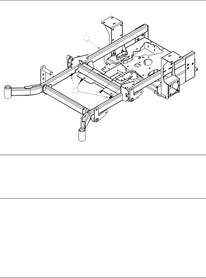
Nutserts Installation
1
2 
INDEX |
SERVICE |
MFG. |
QTY |
DESCRIPTION |
|
NO. |
PART NO. |
PART NO. |
|||
|
|
||||
1 |
545285 |
349605 |
1 |
TRACTOR FRAME (60") |
|
|
545350 |
347534 |
1 |
TRACTOR FRAME (52") |
|
|
545806 |
362657 |
1 |
TRACTOR FRAME (72”) |
|
2 |
N/A |
808493 |
4 |
3/8-16 THREAD NUTSERT |
NOTES:
2-2 |
350165 5/02 |
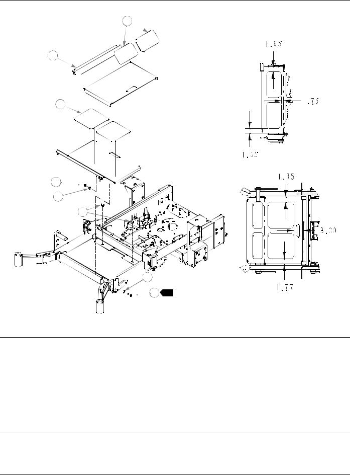
Footrest Assembly
1
2
3
4 


5
6


 5
5


 7 1
7 1
INDEX |
SERVICE |
MFG. |
QTY |
DESCRIPTION |
|
NO. |
PART NO. |
PART NO. |
|||
|
|
||||
1 |
359547 |
359547 |
2 |
STEP TREAD |
|
2 |
348276 |
348276 |
1 |
FLOOR |
|
3 |
305615 |
305615 |
2 |
PLATFORM STEP TREAD |
|
4 |
086660 |
086660 |
2 |
NT .375-16 HX LK NY |
|
5 |
767954 |
767954 |
4 |
FW .406 X .812 X .060 SAE HD ZN |
|
6 |
781880 |
781880 |
2 |
RUBBER BUMPER |
|
7 |
052860 |
052860 |
2 |
CS .375-16 X 1.250 HX G5 ZN |
NOTES:
1.Do not tighten, Item 2 (348276 Floor) must be able to pivot on these bolts.
350165 5/02 |
2-3 |

2-4 |
350165 5/02 |
Chapter 3 Contents
Hydraulic System Installation. . . . . . . . . . . . . . . . . . . . . . . . . . . . . . . 3-2
350165 5/02 |
3-1 |
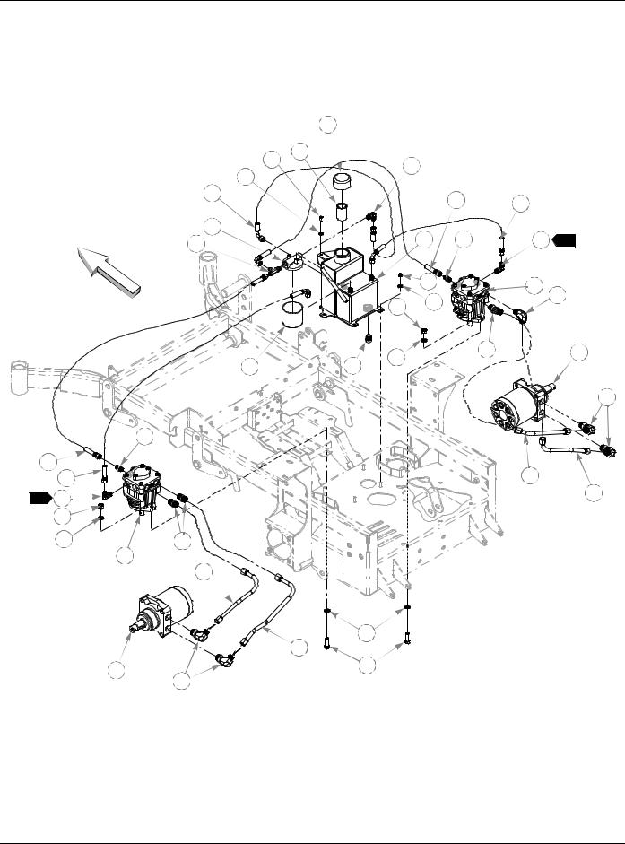
Hydraulic System Installation
|
4 |
|
2 |
3 |
|
17 |
||
|
1
FRONT
16 |
|
|
19 |
18 |
|
|
|
|
|
||
|
|
|
|
|
|
15 |
|
5 |
20 |
17 |
3 |
31 |
|
||||
|
|
|
|
|
|
|
|
6 |
|
8 |
|
|
|
|
|
22 |
|
|
10 |
7 |
|
|
|
|
|
|
|
||
|
|
|
|
|
|
|
11 |
|
21 |
|
12 |
14 |
|
|
|
|
|
23 |
|
|
|
|
24
|
|
20 |
30 |
|
26 |
|
18 |
|
3 |
17 |
25 |
|
||
|
10 |
|
|
11 |
29 |
|
|
9 |
|
28 |
|
|
11 |
|
|
27 |
|
12 |
13 |
|
24 |
||
|
3-2 |
350165 5/02 |

Hydraulic System Installation
ITEM |
SERVICE |
MFG. |
QTY |
|
NO. |
PART NO. |
PART NO. |
||
|
||||
1 |
768515 |
768515 |
2 |
|
2 |
055947 |
055947 |
2 |
|
3 |
032771 |
032771 |
1 |
|
4 |
032763 |
032763 |
1 |
|
5 |
349860 |
349860 |
1 |
|
6 |
034272 |
034272 |
4 |
|
7 |
768523 |
768523 |
4 |
|
8 |
781062 |
781062 |
1 |
|
9 |
781047 |
781047 |
1 |
|
10 |
041707 |
041707 |
4 |
|
11 |
704742 |
704742 |
8 |
|
12 |
781054 |
781054 |
2 |
|
13 |
705186 |
705186 |
4 |
|
14 |
768341 |
768341 |
1 |
|
15 |
768333 |
768333 |
1 |
|
16 |
781575 |
N/A |
1 |
|
17 |
763946 |
N/A |
3 |
|
18 |
778985 |
N/A |
2 |
|
19 |
781591 |
N/A |
1 |
|
20 |
779132 |
N/A |
2 |
|
21 |
781559 |
N/A |
1 |
|
22 |
781542 |
N/A |
1 |
|
23 |
781658 |
N/A |
1 |
|
24 |
781526 |
N/A |
4 |
|
25 |
781500 |
N/A |
1 |
|
26 |
781492 |
N/A |
1 |
|
27 |
781484 |
N/A |
1 |
|
28 |
781476 |
N/A |
1 |
|
29 |
781534 |
N/A |
2 |
|
30 |
781518 |
N/A |
1 |
|
31 |
763953 |
N/A |
1 |
|
|
N/A |
781469 |
1 |
DESCRIPTION
FW .281 X .625 X .051/.080 HD ZN/YL CS .250-20 X .500 HX G5 ZN STRAINER
BREATHER CAP
RESERVOIR
NT .312-18 HX G5 ZN
FW .343 X .687 X .051/.080 HD ZN/YL HYDRO-GEAR PUMP, BDP-10A-300 HYDRO-GEAR PUMP BDP-10A-400 NT .437-14 HX G5 ZN
FW .453 X .812 X .060 ZN ROSS/PARKER WHEEL MOTOR, MB-15 CS .437-14 X 1.375 HX G5 ZN
FILTER ELEMENT
FILTER HEAD
-6STR -6 90°, PUSHLOC HOSE 4.75" 90°, -6 O-RING/-6 JIC FITTING
-6STR -6 90°, PUSHLOC HOSE, 13.00" -6STR -6 90°, PUSHLOC HOSE, 15.00" STR-6MORB/-6JIC FITTING
45°, -8MORB/-8MSL FITTING
90°,-8MORB/-8MSL FITTING STR-8-MORB/HEX PLUG
90°, -10MORB/-8MSL FITTING RIGHT LOOP/RP-BM HYDRO TUBE RIGHT LOOP/LP-TM HYDRO TUBE LEFT LOOP/RP-BM HYDRO TUBE LEFT LOOP/LP-TM HYDRO TUBE STR-8MORB/-8MSL FITTING
-6STR -6STR PUSHLOC HOSE, 9.00" -6 O-RING/-6JIC/6JIC T FITTING
MMZ HYDRAULIC KIT (INCLUDES 16-31)
NOTES:
1.Add 3.5 oz. Lubrizol (027912) to new system or when hydraulic oil is changed (see Owner’s Manual).
2.Hydraulic system capacity is 5 US quarts. Fill reservoir to within 1" of top of Item 3 (032771 Strainer)
3.Two of Items 17 (763946 90°, -6 O-Ring/-6 JIC Fitting) must be installed to pumps prior to installing pumps in tractor.
350165 5/02 |
3-3 |

HYDRAULIC SYSTEM CHARGING PROCEDURE
1.Set handles in the neutral position.
2.Start engine at idle.
3.Let run for a minimum of 30 seconds.
4.Stroke handles to forward position.
5.If motors do not turn in 15 seconds return handles to neutral and repeat step 3 and 4 (one time).
6.If motors do not turn after second attempt, shut off the engine and check for oil at the pump.
7.Increase throttle to half speed and work handles through forward and reverse position until the motor operates smoothly throughout the entire speed range.
3-4 |
350165 5/02 |

Chapter 4 Contents
Battery Installation . . . . . . . . . . . . . . . . . . . . . . . . . . . . . . . . . . . . . . . 4-2
Deck Lift Assembly . . . . . . . . . . . . . . . . . . . . . . . . . . . . . . . . . . . . . . 4-4
Steering and Brake Assembly . . . . . . . . . . . . . . . . . . . . . . . . . . . . . . 4-6
Pump Belt and Pulley Installation . . . . . . . . . . . . . . . . . . . . . . . . . . 4-10
Deck Lift Spring 782995 . . . . . . . . . . . . . . . . . . . . . . . . . . . . . . . . . 4-12
Deck Lift Indicator 783001 . . . . . . . . . . . . . . . . . . . . . . . . . . . . . . . . 4-13
350165 5/02 |
4-1 |
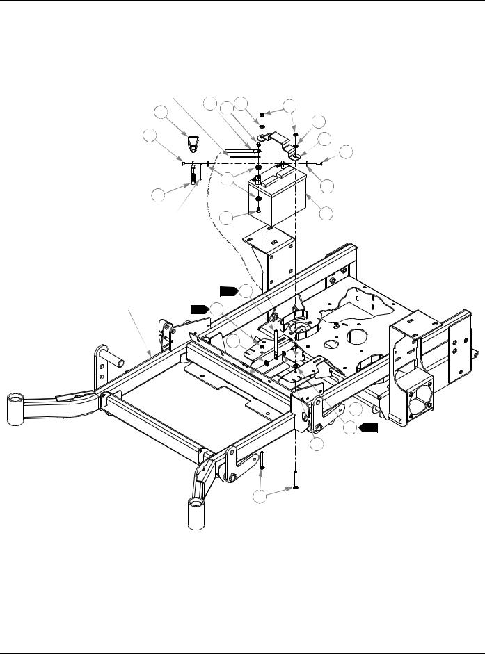
Battery Installation
BLACK WIRE,
PART OF WIRE
HARNESS
3 |
1 |
5 |
6 |
2 |
|
|
|
1
|
9 |
|
4 |
|
|
RED WIRE, |
8 |
|
PART OF WIRE |
||
|
||
HARNESS |
|
TRACTOR |
|
1 |
3 |
|
|
|
|
FRAME |
2 |
11 |
|
|
|
||
|
|
14 |
|
13
5
7
8
9
10
12
11 2
5
4-2 |
350165 5/02 |

Battery Installation
INDEX |
SERVICE |
MFG. |
QTY |
DESCRIPTION |
|
NO. |
PART NO. |
PART NO. |
|||
|
|
||||
1 |
024927 |
024927 |
2 |
NT .250-20 HX GR.5 ZN |
|
2 |
771428 |
771428 |
1 |
RED BATTERY CABLE BOOT |
|
3 |
768820 |
768820 |
1 |
BATTERY GROUND CABLE |
|
4 |
744276 |
744276 |
1 |
POSITIVE BATTERY CABLE |
|
5 |
768523 |
768523 |
3 |
FW .343 X .687 X .051/.080 HD ZN/YL |
|
6 |
058776 |
058776 |
2 |
NT .312-18 HX NL ZN |
|
7 |
348417 |
348417 |
1 |
BATTERY CLAMP STRAP |
|
8 |
055939 |
055939 |
2 |
CS .250-20 X .750 HX G5 ZN |
|
9 |
029868 |
029868 |
4 |
LW .250 INT-EXT TOOTH ZN |
|
10 |
740696 |
740696 |
1 |
BATTERY |
|
11 |
034272 |
034272 |
2 |
NT .312-18 HX G5 ZN |
|
12 |
034280 |
034280 |
1 |
CS .312-18 X .750 HX G5 ZN |
|
13 |
779850 |
779850 |
2 |
CB .312-18 X 3.00 FUL ZN |
|
14 |
029876 |
029876 |
1 |
LW .312 INT-EXT TOOTH ZN |
NOTES:
1.Battery ground cable and black wire of harness should not be connected to battery until engine is ready to be started. See Owners Manual.
2.Items 12 (034272 NT .312-18 HX G5 ZN) to be tightened against frame to lock Items 14 (779850 CB .312-18 X 3.00 FUL ZN) to frame.
350165 5/02 |
4-3 |

Deck Lift Assembly
|
1 |
|
|
|
|
|
2 |
|
|
|
|
|
4 |
5 |
6 |
|
|
|
|
|
|
|
|
TRACTOR |
3 |
|
|
|
|
FRAME |
|
|
|
|
|
|
|
|
|
|
|
|
|
|
|
4 |
5 |
|
5 |
|
|
|
|
|
12 |
|
|
|
|
|
11 |
|
|
|
|
|
4 |
|
10 |
1 |
|
5
6
|
|
5 |
|
|
|
|
|
13 |
|
10 |
1 |
10 |
1 |
|
8 |
|
|
|
|
|
|||
7 |
|
|
|
|
|
4 |
5 |
|
4 |
|
|
|
|
|
4 |
|
|
|
|
10 |
1 |
9 |
8 |
4 |
|
|
|
|
9 |
|
|
|
|
|
 14 8
14 8 
4
9 
4-4 |
350165 5/02 |

Deck Lift Assembly
ITEM |
SERVICE |
MFG. |
QTY |
DESCRIPTION |
|
NO. |
PART NO. |
PART NO. |
|||
|
|
||||
1 |
348318 |
348318 |
1 |
STOP HANDLE |
|
2 |
348284 |
348284 |
1 |
HEIGHT ADJ STOP |
|
3 |
783001 |
783001 |
1 |
DECK LIFT INDICATOR SUBASSEMBLY |
|
4 |
704643 |
704643 |
8 |
NT .437-14 HX FLG ZN |
|
5 |
781294 |
781294 |
7 |
CLIP E, 1.00 X .625 X .050 |
|
6 |
782995 |
782995 |
2 |
DECK LIFT SPRING SUBASSEMBLY |
|
7 |
781229 |
781229 |
1 |
CE .750 X 2.25 X 1.75 HEADLESS |
|
8 |
055749 |
055749 |
3 |
CS .437-14 X 1.750 HX G5 ZN |
|
9 |
348391 |
348391 |
4 |
DECK LIFT CHAIN |
|
10 |
015495 |
015495 |
4 |
STRAIGHT GREASE FITTING |
|
11 |
034272 |
034272 |
1 |
NT .312-18 HX G5 ZN |
|
12 |
756270 |
756270 |
1 |
CS .312-18 X 1.50 FUL THR GR5 ZN |
|
13 |
348458 |
348458 |
1 |
DECK LEVELER YOKE |
|
14 |
781831 |
781831 |
1 |
CS .437-14 X 1.750 FUL THD G5 ZN |
NOTES:
1. Apply grease to zerks on new assemblies.
350165 5/02 |
4-5 |

Steering and Park Brake Assembly
1 |
|
|
|
11 |
12 |
|
|
|
|
|
|
|
|
|
|
||
|
|
|
|
|
|
13 |
|
|
|
10 |
3 |
|
|
|
|
|
|
|
8 |
|
|
|
|
|
22 |
|
|
|
|
|
6 |
23 |
|||
2 |
|
|
|
|
|
|||
|
|
|
|
|
|
|
|
|
3 |
6 |
|
|
|
|
24 |
|
24 |
|
|
|
|
|
|
|
||
|
|
|
|
|
|
7 |
25 |
|
|
|
|
6 |
|
|
7 |
||
|
14 |
7 |
|
|
6 |
|
||
|
|
16 |
17 |
18 |
|
|||
|
|
33 |
|
|||||
4 |
7 |
|
|
|
3 |
|
|
26 |
|
|
|
|
|
|
|
||
5 |
|
|
|
|
20 |
|
7 |
27 |
|
|
3 |
|
|
|
|||
|
5 |
|
|
|
9 |
|
||
|
|
|
21 |
|
28 |
|||
|
|
|
|
19 |
||||
|
|
|
|
|
||||
|
3 |
|
|
|
|
|||
|
|
|
|
|
|
43 |
|
|
|
3 |
|
|
|
|
|
|
|
|
3 |
15 |
47 |
10 |
|
4 |
|
|
|
9 |
|
|
|
||||
|
|
|
|
5 |
|
|
|
|
|
|
|
|
|
|
|
|
|
|
|
10 |
3 |
|
|
|
39 |
|
|
|
31 |
38 |
|
|
|
3 |
|
|
|
|
|
|
|
|
|
45 |
32 |
|
31 |
|
|
|
||
|
|
|
|
|
|
|
33 |
|
|
|
|
7 |
|
37 |
|
34 |
|
|
|
1 |
44 |
|
36 |
|
|
|
|
||
|
|
|
35 |
2 |
3 |
|
|
|
30 29 |
3 |
3 |
|
|
|
||
3 |
40 |
|
|
|
|
||
41 |
|
|
|
42 |
3 |
|
|
6 |
|
|
|
39 |
|
|
|
7 |
|
|
|
3 |
33 |
|
|
|
|
||
3 |
|
46 |
|
15 4 |
TRACTOR |
||
32 |
FRAME
4-6 |
350165 5/02 |
Steering and Park Brake Assembly
|
ITEM |
SERVICE |
MFG. |
QTY |
DESCRIPTION |
|
NO. |
PART NO. |
PART NO. |
||
|
|
|
|||
1 |
781260 |
781260 |
2 |
STEERING BAR GRIP |
|
2 |
348755 |
348755 |
2 |
STEERING BAR |
|
3 |
767954 |
767954 |
48 |
FW .406 X .812 X .060 SAE HD ZN |
|
4 |
036244 |
036244 |
10 |
CS .375-16 X 1.000 HX G5 ZN |
|
5 |
705178 |
705178 |
6 |
CS .375-16 X 1.750 HX G5 ZN |
|
6 |
041152 |
041152 |
8 |
NT .312-24 HX ZN |
|
7 |
768523 |
768523 |
18 |
FW .343X .687 X .051/.080 HD ZN/YL |
|
8 |
348946 |
348946 |
2 |
STEERING ARM MOUNT |
|
9 |
348888 |
348888 |
1 |
STEERLEVER SUPPORT LH |
|
|
|
348714 |
348714 |
1 |
STEERLEVER SUPPORT RH |
10 |
055822 |
055822 |
8 |
CS .375-16 X .750 HX G5 ZN |
|
11 |
781716 |
781716 |
2 |
SS .500-13 X 1.75 SH ZN |
|
12 |
053199 |
053199 |
2 |
NT .500-13 HX JAM ZN |
|
13 |
348987 |
348987 |
1 |
STEERING CONTROL PANEL |
|
14 |
348862 |
348862 |
4 |
STEERLEVER BUSHING |
|
15 |
086660 |
086660 |
8 |
NT .375-16 HX LK NY |
|
16 |
781583 |
781583 |
2 |
BRAKE ROD ASSEMBLY |
|
17 |
350413 |
350413 |
2 |
NEUTRAL STOP YOKE ASSEMBY |
|
18 |
076745 |
076745 |
2 |
CE .375 X 1.125 .15 X .968 ZN |
|
19 |
760199 |
760199 |
2 |
CP .125D X .750 LG ZN |
|
20 |
063198 |
063198 |
4 |
CS 10-24 X .750 HXFLK ZN |
|
21 |
781211 |
781211 |
2 |
PUSH BUTTON SWITCH |
|
22 |
781286 |
781286 |
2 |
PUMP ROD ADJUSTER ASSEMBLY |
|
23 |
781088 |
781088 |
2 |
DAMPENER |
|
24 |
781922 |
781922 |
4 |
DAMPENER BALL STUD |
|
25 |
704163 |
704163 |
2 |
CS .250-20 X 2.00 HX G5 ZN |
|
26 |
768515 |
768515 |
4 |
FW .281 X .625 X .051/.080 HD ZN/YL |
|
27 |
068551 |
068551 |
2 |
NT .250-20 HX NL ZN |
|
28 |
350454 |
350454 |
1 |
L.S PUMP ARM |
|
|
|
348979 |
348979 |
1 |
R.S PUMP ARM |
29 |
348797 |
348797 |
2 |
ADJUSTABLE PIVOT |
|
30 |
781153 |
781153 |
4 |
BUSHING |
|
31 |
005116 |
005116 |
4 |
CS .375-16 X 1.375 HX G5 ZN |
|
32 |
054502 |
054502 |
4 |
NT .375-16 HX GRD 5 ZN |
|
33 |
034272 |
034272 |
8 |
NT .312-18 HX G5 ZN |
|
34 |
781765 |
781765 |
2 |
BRAKE DRUM-HUB ASSEMBLY |
|
|
35 |
781112 |
781112 |
1 |
BRAKE ASSEMBLY |
7 |
|||||
|
|
781351 |
781351 |
1 |
BRAKE ASSEMBLY |
8 |
|
||||
36 |
036236 |
036236 |
4 |
CS .312-18 X 1.000 HX G5 ZN |
|
37 |
350272 |
350272 |
2 |
BRAKE ARM EXTENSION |
|
|
|
350330 |
350330 |
1 |
L.S. BRAKE PIVOT ARM |
38 |
350264 |
350264 |
1 |
R.S. BRAKE PIVOT ARM |
|
39 |
765339 |
765339 |
4 |
BUSHING |
|
40 |
059832 |
059832 |
4 |
NT #10-24 HX NL ZN |
|
41 |
018861 |
018861 |
2 |
COMPRESSION SPRING |
|
42 |
718791 |
718791 |
2 |
NT .375-24 NYLOCK ZN |
|
43 |
782979 |
782979 |
2 |
CS .375-16 X 4.75 HX G5 ZN |
|
44 |
065516 |
N/A |
2 |
ROSS CASTLE NUT |
|
45 |
350397 |
350397 |
2 |
BRAKE LINK TURNBUCKLE |
|
350165 5/02 |
4-7 |
ITEM |
SERVICE |
MFG. |
QTY |
DESCRIPTION |
|
NO. |
PART NO. |
PART NO. |
|||
|
|
||||
46 |
064337 |
N/A |
2 |
ROSS KEY |
|
47 |
781716 |
781716 |
2 |
SS .500-13 X 1.75 SH ZN |
NOTES:
1.Torque to 350-375 ft.-lbs. Included with wheel motor.
2.Torque brake assembly mounting bolts to 100 ft.-lbs.
3.Pin to be clean and free of rust. Apply thin coat of grease prior to installing Item 30 (781153 Bushing).
4.Do not torque this fastener, should be snug but allow Item 38 (350330 Brake Pivot Arm) to pivot freely.
5.Item 29 (348797 Adjustable Pivot) to be adjusted such that Item 9
(348888/348714 Steerlever Support) has no end play.
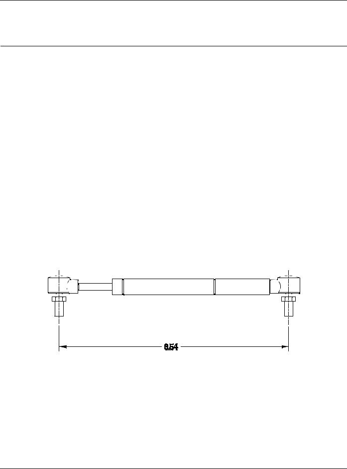
6.See Fig. 1 for initial installation of Item 23 (Dampener)
7.781112 used on right wheel.
8.781351 used on left wheel.
9.With Steering Bars in park position, adjust Push Button Switch (Item 21) outboard until switch is activated by Brake Pivot Arm (Item 38). Repeat for opposite side.
10.Apply Loctite 609 on threads. Fill hex of set screw with 3M EC-1252 tamper proof sealant after adjustments are complete.
NEUTRAL ADJUSTMENT
Fig. 1
4-8 |
350165 5/02 |

This page intentionally left blank.
350165 5/02 |
4-9 |
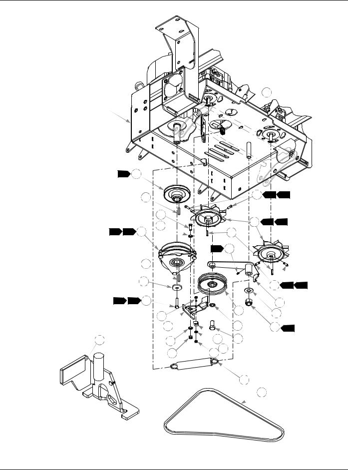
Pump Belt and Pulleys Installation
1
TRACTOR
FRAME
1 |
2 |
|
|
|
|
|
|
|
|
3 |
|
9 |
6 |
4 |
|
|
|
|
|
|
|
|
|
|
|
4 |
|
10 |
1 |
2 |
|
|
|
5 |
|
|
|||
8 |
1 |
|
|
|
|
|
|
6 |
|
11 |
|
|
|
||
|
|
|
5 |
15 |
|
|
|
|
|
3 |
|
|
|
|
|
|
|
7 |
|
|
9 |
6 |
4 |
|
|
|
|
|
|||
4 |
3 |
8 |
|
|
12 |
|
|
|
|
|
|
|
|
||
|
|
19 |
|
16 |
13 |
|
|
|
|
|
|
|
|||
|
|
|
|
|
|
|
|
|
|
20 |
|
17 |
14 |
7 |
|
27 |
|
5 |
22 |
18 |
|
|
|
|
|
21 |
24 23 |
|
|
|
|
|
|
|
|
25 |
|
|
|
|
|
|
|
26 |
|
|
|
LOCATION OF
RUBBER BUMPER
4-10 |
350165 5/02 |

Pump Belt and Pulleys Installation
|
INDEX |
SERVICE |
MFG. |
QTY |
|
NO. |
PART NO. |
PART NO. |
|
|
|
|||
1 |
748681 |
748681 |
1 |
|
2 |
779876 |
779876 |
1 |
|
3 |
212076 |
212076 |
2 |
|
4 |
036244 |
036244 |
1 |
|
5 |
767954 |
767954 |
2 |
|
6 |
781039 |
781039 |
1 |
|
7 |
783829 |
783829 |
1 |
|
8 |
763391 |
763391 |
1 |
|
9 |
083196 |
083196 |
4 |
|
|
9 |
030601 |
N/A |
4 |
|
||||
10 |
325308 |
325308 |
2 |
|
11 |
768127 |
768127 |
2 |
|
12 |
349761 |
349761 |
1 |
|
13 |
025296 |
025296 |
1 |
|
14 |
061101 |
061101 |
1 |
|
15 |
015495 |
015495 |
1 |
|
16 |
781856 |
781856 |
1 |
|
17 |
028118 |
028118 |
1 |
|
18 |
781872 |
781872 |
1 |
|
19 |
055939 |
055939 |
1 |
|
20 |
362392 |
362392 |
1 |
|
21 |
054502 |
054502 |
1 |
|
22 |
778738 |
778738 |
1 |
|
23 |
768515 |
768515 |
1 |
|
24 |
024927 |
024927 |
1 |
|
25 |
781302 |
781302 |
1 |
|
26 |
781443 |
781443 |
1 |
|
27 |
781918 |
781918 |
1 |
|
DESCRIPTION
GM .75 X 1.35 X 1.06 X .18 GROMMET ENGINE SC SINGLE PULLEY
KEY 1/4 SQ X 1.50 LONG
CS .375-16 X 1.000 HX G5 ZN
FW .406 X .812 X .060 SAE HD ZN CLUTCH
FW .460 X 1.750 X .250 ZNYC CS .437-20 X 1.750 G5 ZN
SS.312-18 X .750 SQ-HD ZN SS .312-18 X .500 SH NL PULLEY & FAN
KEY 5MM X 30MM RADIUS ENDS PUMP IDLER ARM
FW .760 X 1.625 X .08 ZN NT .750-10 HX NL ZN
STRAIGHT GREASE FITTING IDLER PULLEY
FW .62 X 1.00 X.134 ZN
CS .625-11 X 1.25 HX G5 ZN CS .250-20 X .750 HX G5 ZN CLUTCH ANCHOR BRACKET NT .375-16 HX GRD 5 ZN
.312 WIRING CLAMP
FW .281 X .625 X .051/.080 HD ZN/YL NT .250-20 HX GR.5 ZN
IDLER SPRING
A-SEC PUMP IDLER BELT
RUBBER BUMPER
NOTES:
1.Coat ID with anti seize.
2.Set blade tips .12"±.03" from surface of engine plate.
3.Torque to 45-48 ft-lbs.
4.Use Loctite 242 on threads.
5.Apply grease at zerk.
6.Torque to 12-15 ft-lbs.
7.Do not torque Item 14 (NT .750-10 HX NL ZN), Item 12 (349761 Pump
Idler Arm) should pivot freely.
8.Electric clutch burnishing procedure: After installing a new clutch it is important to burnish the clutch to insure maximum deck clutch life. In an open area with no bystanders set the engine speed to half throttle. Cycle the deck clutch on for 15 seconds, and then off for 15 seconds. Repeat this operation 10 times, it will require about 5 minutes to complete.
9.On tractors with serial numbers prior to 01082125.
350165 5/02 |
4-11 |
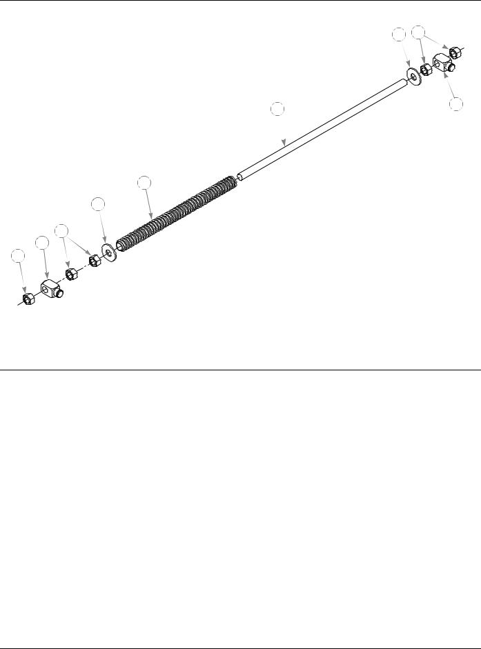
Deck Lift Spring 782995
3 1
5 |
2 |
|
4
3
1
2
1
INDEX |
SERVICE |
MFG. |
QTY |
DESCRIPTION |
|
NO. |
PART NO. |
PART NO. |
|||
|
|
||||
1 |
016972 |
N/A |
5 |
NT .625-11 HX G5 ZNYC |
|
2 |
781187 |
N/A |
2 |
DECK LIFT BLOCK |
|
3 |
017152 |
N/A |
2 |
FW .680 X 1.750 X .14 SAE ZNYC |
|
4 |
781401 |
N/A |
|
DECK LIFT SPRING |
|
5 |
781138 |
N/A |
1 |
DECK LIFT THREADED ROD |
NOTES:
4-12 |
350165 5/02 |
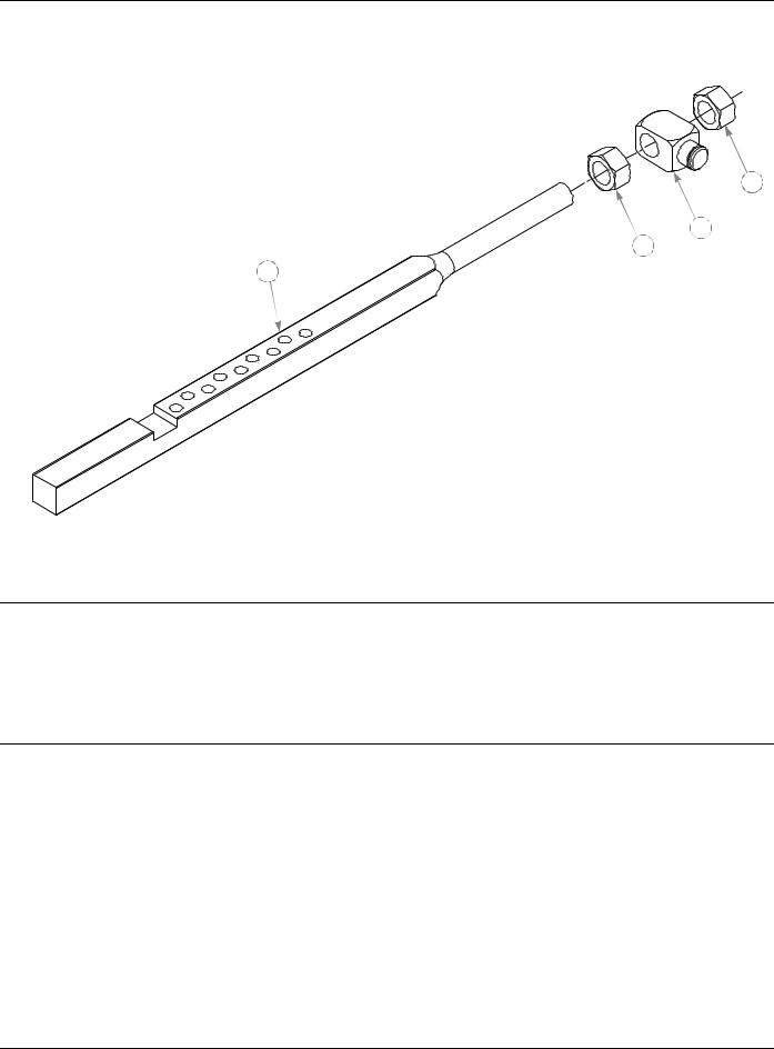
Deck Lift Indicator 783001
2
3
2
1
INDEX |
SERVICE |
MFG. |
QTY |
DESCRIPTION |
|
NO. |
PART NO. |
PART NO. |
|||
|
|
||||
1 |
781203 |
N/A |
1 |
DECK LIFT HEIGHT INDICATOR |
|
2 |
008417 |
N/A |
2 |
N .750-10 HX G ZNYC |
|
3 |
781930 |
N/A |
1 |
DECK LIFT 3/4" BLOCK |
NOTES:
350165 5/02 |
4-13 |
Loading...