


 Loading...
72" QuadcyclerTM
Quadcycler Deck
Parts Manual
•••••••
Hustler Turf Equipment
•••••
P.O. Box 7000
•••
Hesston, Kansas
•
67062-2097
339622 8/06

Table of Contents
Chapter 1
General Information . . . . . . . . . . . . . . . . . . . . . . . . . . . . . . . . . . . . 1-1
Chapter 2 Contents
Deck Assembly . . . . . . . . . . . . . . . . . . . . . . . . . . . . . . . . . . . . . . . . 1-2
Deck Subassembly . . . . . . . . . . . . . . . . . . . . . . . . . . . . . . . . . . . . . 1-4
Spindle Assembly - 506212 . . . . . . . . . . . . . . . . . . . . . . . . . . . . . . 1-7
Chapter 3 Contents
Gauge Arm Assembly - 466888 . . . . . . . . . . . . . . . . . . . . . . . . . . . 3-2
Chapter 4 Contents
Gearbox Breakdown - 532861 (WSI) . . . . . . . . . . . . . . . . . . . . . . . 4-2
Gearbox Breakdown - 532861 (Agrigear) . . . . . . . . . . . . . . . . . . . . 4-4
Chapter 5 Contents
Air Deflector Kit - 470344 . . . . . . . . . . . . . . . . . . . . . . . . . . . . . . . . 5-2
Floatation Kit - 469189 . . . . . . . . . . . . . . . . . . . . . . . . . . . . . . . . . . 5-4
Chapter 6 Contents
Decal Group . . . . . . . . . . . . . . . . . . . . . . . . . . . . . . . . . . . . . . . . . . 6-2
Index . . . . . . . . . . . . . . . . . . . . . . . . . . . . . . . . . . . . . . . . . . . . . . . . . . . . . . . . i-1
336229 9/00

336229 9/00

Chapter 1
General Information
This manual covers 72” Quadcycler Deck model: 925107
Frequently Ordered Parts
PART NO. |
DESCRIPTON |
084178 |
Double Angle V-Belt |
754853 |
24" Blade |
506212 |
Spindle Housing Assembly |
|
|
Service Literature
PART NO |
DESCRIPTION |
084210 72" Quadcycler Owner’s Manual
033514 72” Quadcycler Deck Assembly Instructions
Note: When ordering parts, you must use the service part number as shown for each part, not the index number. Always give the tractor model and serial number and the engine model and serial number to your parts and service representative.
Note: Items sold in bulk such as seals and hoses are sold by the foot.
Using this manual
Illustrations used were current at the time of printing, but subsequent production changes may cause your machine to vary slightly in detail. Excel Industries, Inc. reserves the right to redesign and change the machine as deemed necessary, without notification. If a change has been made to your machine which is not reflected in this parts manual, see your Hustler dealer for current information and parts.
339622 8/06 |
1-1 |

Hardware Description Codes & Abbreviations
The following codes are used throughout this parts manual. Refer to this list when ordering parts..
ABBREVIATION DESCRIPTION
CB |
Carriage Bolt |
CE |
Clevis Pin |
CP |
Cotter Pin |
CS |
Cap Screw |
CW |
Cup Washer |
FDRW |
Fender Washer |
FW |
Flat Washer |
HX |
Hex Head |
ID |
Inside Diameter |
LW |
Lock Washer |
MB |
Machine Bushing |
MS |
Machine Screw |
NT |
Nut |
OD |
Outside Diameter |
SC |
Self Tapping Cap Screw |
SH |
Socket Head |
SB |
Shoulder Bolt |
SS |
Set Screw |
Standard Torques
The following chart lists the standard torque values for the threaded fasteners found in this manual. Torque all cap screws, nuts and set screws to these values unless a different torque is shown in the Notes section next to the fastener.
SIZE |
FT-LBS |
NM |
SIZE |
FT-LBS |
NM |
.250 |
8.2 |
11.1 |
M3 |
1 |
1.3 |
.312 |
17 |
23 |
M4 |
2.2 |
3 |
.375 |
30 |
40 |
M5 |
4.5 |
6.1 |
.438 |
48 |
65 |
M6 |
7.7 |
10.4 |
.500 |
73 |
99 |
M8 |
18.5 |
25 |
.562 |
105 |
143 |
M10 |
37 |
50 |
.625 |
145 |
200 |
M12 |
64 |
87 |
.750 |
260 |
350 |
M16 |
160 |
215 |
.875 |
420 |
565 |
M20 |
320 |
435 |
1.00 |
625 |
850 |
M24 |
555 |
750 |
NOTE:
Lubricate all grease zerks
1-2 |
339622 8/06 |

Chapter 2 Contents
Deck Assembly . . . . . . . . . . . . . . . . . . . . . . . . . . . . . . . . . . . . . . . . . 2-2
Deck Subassembly . . . . . . . . . . . . . . . . . . . . . . . . . . . . . . . . . . . . . . 2-4
Spindle Assembly . . . . . . . . . . . . . . . . . . . . . . . . . . . . . . . . . . . . . . . 2-7
339622 8/06 |
2-1 |

Deck Assembly
|
|
|
|
1 |
|
|
|
|
2 |
|
3 |
|
|
|
|
|
4 |
|
17 |
19 |
|
|
1 |
|
|
|
|
||
|
|
20 |
|
|
2 |
|
|
|
|
|
|
|
18 |
|
22 |
|
5 |
|
|
|
|
||
|
|
|
23 |
|
|
|
|
|
8 |
|
|
|
|
|
|
|
|
|
21 |
|
|
|
7 |
|
|
|
|
6 |
|
|
|
|
|
|
|
|
15 |
|
|
9 |
13 |
1 |
16 |
|
|
|
|
29 |
20 |
11 |
|
||
|
|
|
|||
|
28 |
|
31 |
|
8 |
|
|
|
30 |
32 |
14 |
|
|
|
|
|
10 |
|
25 |
33 |
|
|
|
|
26 |
|
|
|
|
|
27 |
|
|
|
7 |
|
|
|
|
|
8 |
38 |
2 |
|
|
|
|
|
|
|
|
|
36 |
|
24 |
|
|
|
9 |
|
|
|
|
|
|
|
19 |
|
|
|
|
|
|
12 |
11 |
20 |
37 |
|
|
19 |
24 |
||
|
|
|
|
24 |
|
|
|
|
|
|
 20 19
20 19
7
8
34
35
2-2 |
339622 8/06 |

Deck Assembly
INDEX |
SERVICE |
MFG. PART |
QTY. |
DESCRIPTION |
|
NO. |
PART NO. |
NO. |
|||
|
|
||||
1 |
075291 |
075291 |
2 |
CLAMPING KNOB |
|
2 |
076547 |
076547 |
2 |
FW .344 X .688 X .065 SAE ZN |
|
3 |
307124 |
307140 |
1 |
R/H DECK COVER |
|
4 |
307132 |
307157 |
1 |
L/H DECK COVER |
|
5 |
467126 |
467126 |
1 |
ADJUSTER ARM |
|
6 |
074252 |
074252 |
2 |
CS .50-13 X 1.50 HX G5 ZN |
|
7 |
017046 |
017046 |
7 |
LW .50 MEDIUM SPRING ZN |
|
8 |
008193 |
008193 |
7 |
NT .50-13 HX G5 ZN |
|
9 |
017137 |
017137 |
4 |
FW .560 X 1.370 X .109 SAE ZN |
|
10 |
028274 |
028274 |
2 |
CB .50-13 X 1.50 FULL ZN |
|
11 |
058875 |
058875 |
2 |
MB .510 X .870 X .050 ZN |
|
12 |
025601 |
025601 |
1 |
CS .50-13 X 4.620 ZN |
|
13 |
467266 |
467266 |
1 |
RIGHT REAR DISCHARGE DOOR |
|
14 |
467241 |
467241 |
1 |
CENTER REAR DISCHARGE DOOR |
|
15 |
474445 |
474452 |
1 |
DEFLECTOR |
|
16 |
054528 |
054528 |
1 |
BUMPER |
|
17 |
074559 |
074559 |
1 |
GRIP |
|
18 |
467258 |
467258 |
1 |
HANDLE |
|
19 |
024927 |
024927 |
10 |
NT .25-20 HX G5 ZN |
|
20 |
017079 |
017079 |
7 |
FW .250 X .560 X .040 SAE ZN |
|
21 |
467274 |
467274 |
1 |
SIDE DISCHARGE COVER |
|
22 |
055939 |
055939 |
4 |
CS .25-20 X .750 HX G5 ZN |
|
23 |
089789 |
089789 |
4 |
FW .266 X .750 X .060 ZN |
|
24 |
017038 |
017038 |
8 |
LW .250 MEDIUM SPRING ZN |
|
25 |
056077 |
056077 |
2 |
CS .25-20 X 1.00 HX G5 ZN |
|
26 |
287649 |
287649 |
1 |
SIDE DISCHARGE CLIP |
|
27 |
315465 |
315465 |
1 |
CLIP PLATE |
|
28 |
035626 |
035626 |
4 |
NT 10-24 HX ZN |
|
29 |
056176 |
056176 |
4 |
LW #10 MEDIUM SPRING ZN |
|
30 |
758821 |
758821 |
2 |
OVER CENTER LATCH |
|
31 |
025320 |
025320 |
2 |
HP .091 X 1.875 ZN |
|
32 |
016048 |
016048 |
4 |
MS 10-24 X .625 TH SL ZN |
|
33 |
467118 |
467118 |
4 |
PLUG BUTTON |
|
34 |
467175 |
467175 |
1 |
R/H MULCHER BAFFLE |
|
35 |
467167 |
467167 |
1 |
L/H MULCHER BAFFLE |
|
36 |
016527 |
016527 |
2 |
CS .50-13 X 1.00 HX G5 ZN |
|
37 |
537175 |
480228 |
2 |
TIE DOWN BRACKET |
|
38 |
N/A |
466888 |
2 |
GAUGE ARM ASSEMBLY |
|
|
|
|
|
|
NOTES:
1.Supplied with item 15 but may be ordered separately.
2.See Chapter 3 for breakdown.
339622 8/06 |
2-3 |
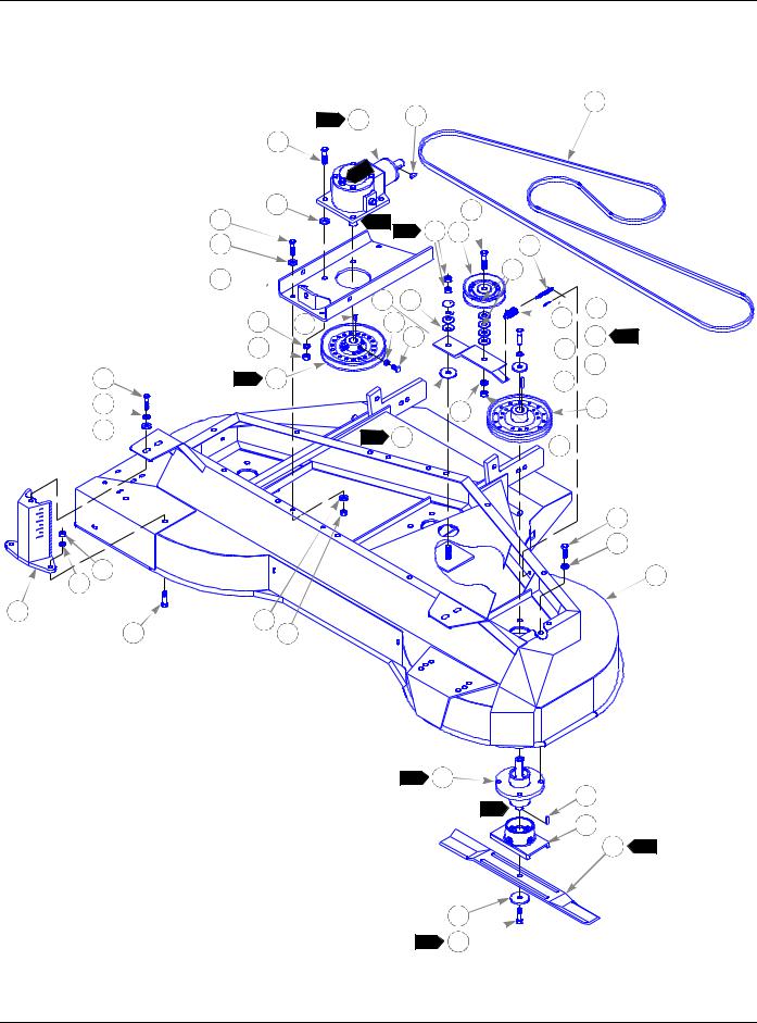
Deck Subassembly
24
4 |
4 |
7 |
2 |
|
|
|
1 |
|
|
1 |
|
3
12
13
8 
5 |
7 |
6 
36 |
1 |
9 |
5 
20 

6
5
37
13
2 |
14 |
18
8
5 6 19
22
20
16 15 

11
10 
5
6 17
2 |
30 |
7
34
3 35


 23
23
 21
21


 25 3
25 3

 5
5
 26
26  27
27
28
6
29
5
1
31
32
33 9
2-4 |
339622 8/06 |
Deck Subassembly
|
|
INDEX |
SERVICE |
MFG. PART |
QTY. |
DESCRIPTION |
|
|
NO. |
PART NO. |
NO. |
||
|
|
|
|
|||
1 |
532820 |
467316 |
1 |
72" 4-WAY DECK ASSEMBLY |
||
2 |
074252 |
074252 |
8 |
CS .50-13 X 1.50 HX G5 ZN |
||
3 |
028118 |
028118 |
4 |
FW .620 X 1.00 X .134 ZN |
||
4 |
532861 |
466664 |
1 |
GEARBOX |
||
5 |
017046 |
017046 |
26 |
LW .50 MEDIUM SPRING ZN |
||
6 |
008193 |
008193 |
11 |
NT .50-13 HX G5 ZN |
||
7 |
036715 |
036715 |
2 |
WOODRUFF KEY |
||
8 |
467100 |
467100 |
1 |
GEARBOX SUPPORT |
||
9 |
467324 |
467324 |
1 |
PULLEY 8” |
||
10 |
042051 |
042051 |
2 |
SS .375-16 X 1.00 SQ-HD ZN |
||
11 |
706168 |
706168 |
2 |
NT .375-16 HX JAM G5 ZN |
||
12 |
773242 |
773242 |
4 |
CS .437-14 X 1.250 HX G5 ZN |
||
13 |
773259 |
773259 |
8 |
FW .50 X 1.250 X .064/.104 SAE F436 ZN |
||
14 |
041707 |
041707 |
4 |
NT .437-14 HX G5 ZN |
||
15 |
068759 |
068759 |
4 |
CW .560 X 1.340 X .050 PN |
||
16 |
315291 |
315291 |
1 |
IDLER ARM BRACKET |
||
17 |
263517 |
263517 |
1 |
BEARING DISC |
||
18 |
078949 |
078949 |
1 |
CS .50-13 X 2.00 G5 ZN |
||
19 |
503748 |
503748 |
1 |
IDLER PULLEY |
||
20 |
017137 |
017137 |
6 |
FW .560 X 1.370 X .109 SAE ZN |
||
21 |
036384 |
036384 |
1 |
IDLER SPRING |
||
22 |
244384 |
244384 |
1 |
IDLER CHAIN |
||
23 |
017277 |
017277 |
1 |
CP .187 X 1.00 LG HML ZN |
||
24 |
084178 |
084178 |
1 |
DOUBLE ANGLE V-BELT |
||
25 |
078378 |
078378 |
3 |
CS .50-20 X 1.50 HX G5 ZN |
||
26 |
078386 |
078386 |
3 |
FW .510 X 1.750 X .187 ZN |
||
27 |
212076 |
212076 |
3 |
KEY .250 X .250 X 1.50 |
||
28 |
504142 |
504142 |
3 |
DRIVE PULLEY 8" |
||
29 |
016527 |
016527 |
12 |
CS .50-13 X 1.00 HX G5 ZN |
||
|
|
30 |
506212 |
249318 |
3 |
SPINDLE HOUSING ASSEMBLY |
|
10 |
|||||
31 |
712372 |
712372 |
3 |
KEY .250 X .250 X .660 |
||
32 |
035808 |
035808 |
3 |
BLADE SADDLE |
||
33 |
754853 |
754853 |
3 |
24" BLADE |
||
34 |
752386 |
752386 |
3 |
CW .515 X 2.250 X .204 ZN |
||
35 |
753798 |
753798 |
3 |
CS .50-20 X 1.750 HX G5 ZN |
||
36 |
705954 |
705954 |
2 |
CS .50-13 X 1.250 HX G5 ZN |
||
37 |
532887 |
466631 |
2 |
GAUGE ARM MOUNT |
||
|
|
|
|
|
|
|
339622 8/06 |
2-5 |

Deck Subassembly
NOTES:
1.Item 9, pulley, must be in the same horizontal plane as the item 28, drive pulleys, within ± .03" tolerance.
2.Assemble item 30, spindle housing, so the grease zerk faces the front of the deck.
3.Torque to 65-75 Ft. Lbs.
4.Item 4, gearbox, to be filled to center of sight gauge upon installation with Amaco 80W-10 or equivalent gear lube.
5.Tighten item 6, nut, to 20 Ft. Lbs. then loosen 1/4 turn.
6.Apply lubrication to both sides of bearing disc. Use Vasoline or 716555 grease.
7.Shaft & exposed end of bearings must be free of rust & wiped clean. Then coat entire shaft & exposed end of bearings with antiseize lubricant 705715.
8.Wipe clean & coat entire surface of shaft with antiseize lubricant 705715.
9.To check proper blade alignment, both ends of center blade must align with both end of outer blades. When blade tips are closest together they must be within .20" vertically.
10.See 2-7 for breakdown.
11.Air vent must be free of paint.
2-6 |
339622 8/06 |
Loading...