


4-BTV, 5-BTV, 6-BTV |
Multiband HF |
Vertical Antennas |
New Assembly and |
High Performance |
Installation |
Instructions |
DXE-BTV-INSTALL GUIDE - Rev 0d |
Cost: $5.00 |
To be certain to get optimum performance from this |
vertical design, please assemble and install your new |
antenna according to these DX Engineering Assembly |
and High Performance Installation Instructions. |
These instructions are intended to replace those |
originally supplied by the manufacturer. |
© DX Engineering 2012 |
P.O. Box 1491 ∙ Akron, OH 44309-1491 |
Phone: (800) 777-0703 ∙ Tech Support and International: (330) 572-3200 |
Fax: (330) 572-3279 ∙ E-mail: DXEngineering@DXEngineering.com |

Table of Contents
Chapter 1 - Introduction |
|
Congratulations ! |
4 |
Over 50 Years Ago |
4 |
Hustler BTV antennas |
5 |
You gotta be kidding me...... |
6 |
Basic Assembly and Enhanced Operating Assembly |
6 |
|
|
Chapter 2 - General Information |
|
Warning |
7 |
Overhead Power Line Safety |
7 |
Basic Tools Required |
7 |
Assembly Notes |
7 |
|
|
Chapter 3 - Common Starting Information |
|
Installation Sequence |
8 |
Site Selection |
9 |
Mounting Pipe |
9 |
Concrete or No Concrete – That is THE Question |
10 |
Coaxial Cable to Mounting Pipe |
11 |
|
|
Chapter 4 - Some Really Good Information |
|
Get the Best Performance From Your New Quarter-Wave Vertical Antenna |
11 |
Some Brief Words on Ground Mounting, Elevated Mounting, and Radial Wires |
12 |
How to Put Radial Wires Down Without Digging |
13 |
Radial System Considerations |
14 |
|
|
Chapter 5 - Basic BTV Assembly |
|
Assembling Vertical Aluminum Antenna Sections & Element Clamps |
17 |
Hustler Base Assembly |
19 |
Hustler 4 BTV - Package Contents & Assembly |
20 |
Hustler 5 BTV - Package Contents & Assembly |
22 |
Six Blade Spider for the 4-BTV and 5-BTV only |
24 |
Three Blade Spider for the 5-BTV only |
24 |
80 Meter Resonator and Whip Installation for the 5-BTV and 6-BTV |
24 |
Hustler 6 BTV - Package Contents & Assembly |
25 |
Mating the Vertical Sections to the Base Section |
27 |
Installing Radials & Feedline on the Hustler Base |
28 |
Coax RF Choke |
29 |
Basic Tuning |
29 |
|
|
Chapter 6 - DX Engineering Enhanced Antenna Systems |
|
Special Hustler BTV Packages Available from DX Engineering |
30 |
Radial Plate to Mounting Pipe |
32 |
Attaching Ground Radial Wires to the Radial Plate |
33 |
Tilt Base Mounting Plate to Mounting Pipe |
34 |
BTV Antenna Base Section to Tilt Base |
34 |
Testing the Tilt Base |
35 |
Alternate Feedpoint Connections |
36 |
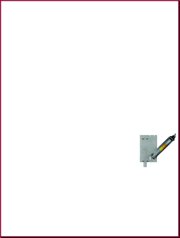
The DXE-VFCC-H05-A Vertical Feedline Current Choke |
37 |
- 2 -

Chapter 7 - Tuning |
|
Understanding Trap Calibration |
39 |
Hustler Traps |
40 |
Hustler Trap Calibration - Resonance Adjustment Procedure |
42 |
Tuning the 80 Meter Resonator Whip for the 5-BTV and 6-BTV |
43 |
|
|
Chapter 8 - Guying the Hustler BTV Antenna System |
44 |
|
|
Chapter 9 - Reference Information |
|
Elevated Mounting of the Hustler BTV Antenna |
45 |
The Quarter-Wave Vertical on a Metal Roof |
46 |
What Trap Do I Have? |
48 |
Hustler BTV Replacement Parts Diagram |
49 |
Weatherproofing Coaxial Cable Connections |
50 |
Lightning Protection - For Any Installation |
50 |
Hustler BTV Specifications |
51 |
|
|
Chapter 10 - Additional Operating Bands |
|
Adding Additional Operating Bands to your Hustler BTV Antenna |
54 |
|
|
Chapter 11 - Recommended Accessory Items |
|
For Assembly |
55 |
For Quick Tilt Action |
55 |
For Tuning |
56 |
|
|
Additional Accessories for Your Hustler BTV |
56 |
|
|
Technical Support and Warranty |
60 |
Note: DX Engineering is constantly upgrading information and developing new products to enhance your amateur radio experience. Please check the DX Engineering web site for the latest information: www.DXEngineering.com
Manual Updates and Information
Every effort is made to supply the latest manual revision with each product. Occasionally a manual will be updated between the time your DX Engineering product is shipped and when you receive it. Please check the DX Engineering web site (www.dxengineering.com) for the latest revision manual.
- 3 -

Chapter 1 - Introduction |
|
Congratulations ! |
4 |
50 Years Ago |
4 |
Hustler BTV antennas |
5 |
You gotta be kidding me...... |
6 |
Basic Assembly and Enhanced Operating Assembly |
6 |
Congratulations on your purchase of one of the most versatile HF multi-band antennas, the Hustler HF Base model 4-BTV, 5-BTV or 6-BTV, or a complete DX Engineering Hustler High Performance HF Vertical System Package: models DXE-HSR-4BTV-P, DXE-HSR-5BTV-P or
DXE-HSR-6BTV-P.
Your new Hustler HF antenna system offers automatically selected multi-band coverage with an omni-directional pattern. The high quality, low-loss traps are adjustable, so you may tune the antenna for low SWR and maximum performance in virtually all types of installations. The Hustler BTV Series HF Base Vertical is mechanically and electrically superior to other brands, and will offer years of top performance. If the system is installed with the DX Engineering Hustler antenna options according to the recommendations and instructions in this manual, the full capabilities of this antenna are realized
DX Engineering has worked extensively with the Hustler BTV series of antennas and has custom manufactured the best quality optional items to enhance the HF operating performance. Using DX Engineering parts will ensure that your Hustler BTV antenna will enable you to achieve an outstanding presence on the amateur bands for years to come.
Over 50 Years Ago!
The Hustler HF Base Four Band Trap Vertical antenna was a new concept in 1959. This unique multiband antenna with an exclusive low-loss trap design was developed and introduced to Amateurs by Hustler, Inc. of Cleveland, Ohio, offering quarter-wave antenna performance for 40, 20 15 and 10 meters , but requiring no band switching!
Later, the Hustler Four Band Trap Vertical, known around the world as the 4-BTV, was made available with an 80 meter resonator, and the 5-BTV was born. When the Amateur bands expanded in 1979, the last of the series offerings designed by Hustler, the 6-BTV, added 30 meters, for an unequalled vertical antenna. Since 1985 the New-Tronics Antenna Corporation in Mineral Wells, Texas, has been making high quality antennas for HF, VHF and UHF Amateur and Commercial customers, including the “Hustler BTV Series”.
Since 2003, DX Engineering has offered Hustler Antennas and has developed a complete system of innovative accessories and Add-On Kits specifically for the Hustler BTV series. Amateurs now have the choice of complete Hustler BTV Series High Performance packages for their HF needs, including the ability to turn their Hustler into a “9-BTV” covering all bands 80 through 10 meters.
DX Engineering joins New-Tronics Antenna Corporation in celebrating over 50 years of service with the famous Hustler HF Base Four Band Trap Vertical – The Hustler 4-BTV.
- 4 -
Hustler BTV Antennas
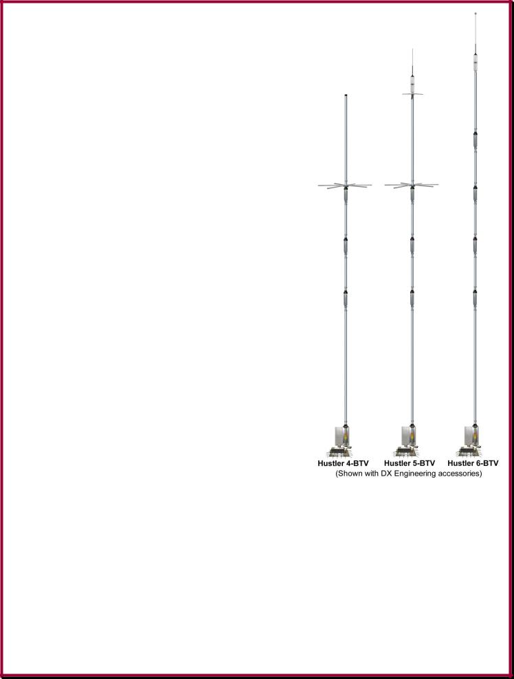
The Hustler 4-BTV is a four-band trap vertical antenna providing an omni directional pattern. The 4-BTV is designed as a self supporting vertical to provide optimum performance on the 10, 15, 20 and 40 meter bands. This antenna is designed for installations with restricted space. The Hustler 4-BTV is approximately 19 feet tall. It can also be adapted to operate on the 75/80 meter band by adding the RM-80S resonator and the 4457-1 three blade spider assembly on top of the 4-BTV. If the 75/80 meter resonator is attached to the 4-BTV, it may be desirable to guy the antenna above the 20 meter trap with small diameter polypropylene rope.
The Hustler 5-BTV is a five-band trap vertical antenna. This antenna includes the RM-80S resonator and the 4457-1 three blade spider assembly. The 5-BTV is designed to provide excellent performance on the 10, 15, 20, 40 and 75/80 meter bands. The Hustler 5-BTV is approximately 24 feet tall.
The Hustler 6-BTV is a six-band trap vertical antenna. The 6-BTV is designed to provide excellent performance on the 10, 15, 20, 30, 40 and 75/80 meter bands, using four traps and the RM-80S resonator. The design of the 6-BTV is sleek, with no capacity spiders and is approximately 25 feet tall.
The Hustler BTV antennas provide automatic electrical selection of the bands through the use of optimum Q traps, which are individually and precisely tuned at New-Tronics.
The traps are parallel tuned circuits which provide efficient isolation between the vertical sections, permitting multi-band operation. Efficient operation over the many ham bands at good SWRs is possible in a proper installation.
The Hustler BTV antennas were designed to provide optimum performance from both an electrical and mechanical standpoint. Mechanically, this antenna boasts a heavy duty base and heavy duty aluminum tubing. The mechanical assembly is accomplished with all stainless steel hardware. The use of clamps permits re-adjustment if necessary, and allows tuning of each band. The mechanical construction is such that guying is not ordinarily needed.
The performance provided by the Hustler BTV antenna is better than any other antenna of this type. Broad banding is such that one setting permits both phone and CW operation on most bands. The antenna provides a nominal 52 Ω base impedance when installed and tuned according to instructions. The radiation efficiency is equivalent to, or greater than, other trap verticals.
- 5 -

You gotta be kidding me......
When you first looked at this manual you probably wondered "What is all this?!?!?!" Do I really need to read all this stuff? Well, this manual was put together using many years of antenna design experience in making the Hustler BTV Vertical Antenna perform to the utmost. DX Engineering has sold thousands of Hustler BTVs with DX Engineering add-on parts that have been engineered, tested and proven to enhance the operation of the Hustler BTV series of antennas.
When you install any antenna, you want the maximum performance and these instructions will help you achieve that goal with the Hustler BTV.
Can you install the antenna without all these extra parts? Sure, but your performance will be far less than optimum.
DX Engineering constantly examines the performance of the Hustler BTV series antennas and continually engineers add-ons to get the best possible HF performance.
When installed using these instructions and DX Engineering accessories, you will have an antenna system that will exceed your expectations and provide you with years of great contacts on the HF Amateur bands!
Basic Assembly and Enhanced Operating Assembly:
We at DX Engineering believe that the Hustler BTV antenna is great and can be installed quickly to get you on the air making contacts.
Through years of experience, DX Engineering has engineered and manufactured add-ons that will make the Hustler BTV performance even better!
Do you need the high performance options now? No, you can get started with the basic system and add enhancements over time. Many hams that have added DX Engineering BTV antenna options have exclaimed the resulting higher performance was like getting a new antenna!
This manual has chapters for:
Basic assembly instructions for those wanting to install a BTV right out of the box with no performance enhancing options. (Chapter 5)
Assembly using DX Engineering options that have been engineered to obtain maximum performance from a BTV antenna system. (Chapter 6)
You'll want to read all the information in order to make an informed decision for your installation. Proper planning for your installation will provide you with years of great operation on the HF bands using the Hustler BTV series antenna. To be certain to get optimum performance from this vertical design, please assemble and install your new antenna according to these DX Engineering Assembly and High Performance Installation Instructions. These instructions may be used in place of those originally supplied by the manufacturer. The Hustler BTV series of antennas is manufactured by New-Tronics Antenna Corporation, Mineral Wells, Texas.
- 6 -
Chapter 2 - General Information |
|
Warning |
7 |
Overhead Power Line Safety |
7 |
Basic Tools Required |
7 |
Assembly Notes |
7 |
WARNING!
INSTALLATION OF ANY ANTENNA NEAR POWER LINES IS DANGEROUS
Warning: Do not locate the antenna near overhead power lines or other electric light or power circuits, or where it can come into contact with such circuits. When installing the antenna, take extreme care not to come into contact with such circuits, because they may cause serious injury or death.
Overhead Power Line Safety
Before you begin working, check carefully for overhead power lines in the area you will be working. Don't assume that wires are telephone or cable lines: check with your electric utility for advice. Although overhead power lines may appear to be insulated, often these coverings are intended only to protect metal wires from weather conditions and may not protect you from electric shock
Keep your distance! Remember the 10-foot rule: When carrying and using ladders and other long tools, keep them at least 10 feet away from all overhead lines - including any lines from the power pole to your home.
Basic Tools Required
Two 7/16" open end wrenches or nut drivers
Medium size flat blade screwdriver or 5/16" nut driver for the element clamps Tape measure
Felt-tip marker
Assembly Notes
Note: DXE-P8A Penetrox A Anti-Oxidant should be used between all antenna element sections. Penetrox is an electrical joint compound to affect a substantial electrical connection between metal parts such as telescoping aluminum tubing or other antenna pieces. It ensures high conductivity at all voltage levels by displacing moisture and preventing corrosion or oxidation.
Note: UMI-81343 Never-Seez or DXE-NSBT8 Anti-Seize should be used on all clamps, bolts and stainless steel threaded hardware to prevent galling and to ensure proper tightening.
- 7 -
Chapter 3 - Common Starting Information |
|
Installation Sequence |
8 |
Site Selection |
9 |
Mounting Pipe |
9 |
Concrete or no concrete - That is THE question |
10 |
Coaxial Cable to Mounting Pipe |
11 |
Installation Sequence
1. |
Site Selection |
7. |
Antenna Assembly |
|
2. |
Installing a Mounting Pipe |
8. |
Mating the BTV antenna to the base section |
|
3. |
Run Coax from Radio to Mounting Pipe |
9. |
Walk the antenna up to normal position |
|
4. |
Install the Radial Plate and Radial System |
10. |
Tuning |
|
5. |
Install the Tilt Base Assembly |
11. |
Add optional DX Engineering Add-On Kits |
|
6. |
Mount the BTV base to the Tilt Base |
|
|
for 12, 17 and 60 meters and make adjustments |
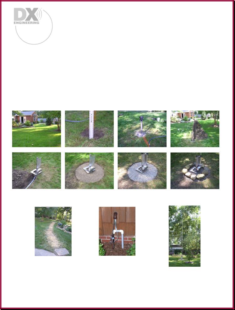
Site Selection |
Hole for Mounting Pipe |
Concrete & Level |
Trench for Coax |
Coax to Base |
Gravel to keep |
Radial Wires Installed |
Rocks added for |
Install Radial Plate |
weeds away |
Antenna Installed |
good looks |
Tilt Base & VFCC |
|
|
|
Trench Filled |
Shack end - Ground Rod |
and new grass seeded |
and PolyPhaser protection |
17 Meter Add-On-Kit Tuned and on the air!
K3EMB's Hustler 6-BTV installation - Total installation time: 3 days
(your time may vary)
- 8 -
Site Selection
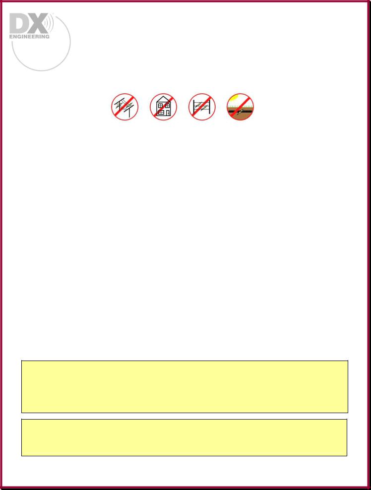
Install your new vertical antenna a minimum of 20 feet away from buildings, wires, metal fences, downspouts and gutters. Centering a vertical antenna in an open area is the best option. Installing the antenna near a wooden fence or on a wood post is okay as long as there is no metal within 20 feet of the antenna.
Installing the antenna on a metal mounting pipe or a wooden post that is set in concrete is okay. Since the radial system wires create the efficient ground return for RF currents, direct earth grounding of the support post or a ground rod is not required at the antenna.
Select a mounting location clear from power lines, structures and other antennas by a minimum of 40 feet (30 + 10 foot safety rule). Consider overhead power lines, utility cables and wires. The further away the vertical is mounted from local noise sources or other metallic objects, which can re-radiate noise and affect the tuning, radiation pattern and SWR, the better. Determine the direction you want the antenna to pivot and make sure there is adequate clearance (at least 30 feet).
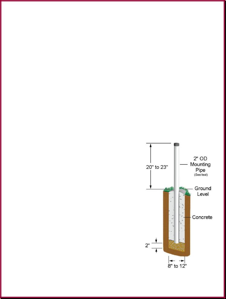
Mounting Pipe
The mounting support may be a galvanized metal pipe or thick wall steel tube from 1 inch to 1-3/4 inches outside diameter (OD) when using just the Hustler bracket, and 1 inch to 2 inches OD when using the DXE-TB-3P Tilt Base. A thick-walled steel pipe with a minimum thickness of 1/8" (1/4" preferred) should be used. The standard 1-1/2" galvanized water
pipe (with its 1.9" OD) is just fine for this application and can usually be found at your local home building supply store. A 4 to 6 inch wood post can also be used.
Use a thick-walled galvanized steel mounting pipe approximately 6 feet long. This will allow approximately 4 feet to be below ground and 20-23 inches above ground.
The height of the mounting pipe above ground level of 20-23 inches will allow you to do either a basic installation, or an enhanced installation by adding the DX Engineering optional items described in this detailed manual. In some cases ham operators have done a basic installation, and then added the DX Engineering optional items at a later date to enhance their operation. Thus, the length of mounting pipe above ground is 20 to 23 inches.
For permanent mounting, use a post-hole digger to make the hole deep enough to accommodate approximately 4 feet of pipe and a couple inches of gravel at the bottom for drainage. Set the pipe on the gravel, use the pre-mix concrete to fill around the pipe, adding water and mixing as you fill (or mix the concrete first, depending on the type you purchase), then pour the
concrete in the hole. Fill the hole until the concrete is level with the ground around it. Use a level as you fill the hole to be sure the pipe is vertically straight. Allow to set overnight.
- 9 -

Your location, landscape and ground conditions may require different mounting solutions in order to have the steel mounting pipe and the vertical antenna in a secure position. You may also attach the Tilt Base to a 4 to 6 inch wooden post at the location you intend to use the antenna, making sure the unit is securely mounted.
Using a cyclone fence is not recommended for a vertical antenna support or being used as a radial system. Poor RF connections and the presence of high levels of noise that are inherent on metal fences make them an undesirable mounting location for any HF vertical antenna.
Note: Steel, rather than aluminum, is much more suitable for mounting in concrete. Aluminum will quickly corrode due to incompatibility with the materials used to make concrete.
Concrete or No Concrete – That is THE Question
The original Hustler BTV installation manuals call for the ground mounting pipe to be driven into the earth with the specific wording “Do not use concrete. Do not dig a hole and bury the mast. It must be driven in.” The reason for this recommendation is so that installations with few or no radials will be able to make use of the direct contact between the mounting pipe and the earth to collect and distribute antenna currents.
Unfortunately, the soil and a steel pipe usually does not provide efficient RF conduction. Therefore, the use of many ground radial wires are recommended for all quarter-wave ground mounted HF antenna, to improve efficiency and performance dramatically.
Also, a driven or pounded pipe may be used on any ground-mounted vertical antenna installation, regardless of the number of radials used.
DX Engineering recommends using a concrete base, as shown on page 9, when a high performance installation with many radials is planned. The reasons that a concrete base is recommended:
1.It is easier to make sure that the mounting pipe is vertical when it is braced for installation with concrete. Pounded pipes can develop a lean or hit a rock while being driven into the ground, which could result in a leaning antenna.
2.A steel pipe or tube in concrete will last much longer than in soil, especially in certain types of soil that will corrode steel more quickly.
3.Concrete is not an insulator for a steel pipe, as the hardened but moist concrete is a good conductor from the steel to the soil for grounding purposes.
4.A ground surface wire radial system offers far more efficient means to collect and distribute surface RF currents than a single pipe in the soil, so a pipe in concrete is okay when using many radials.
-10 -
Coaxial Cable to Mounting Pipe
The coaxial cable should be routed from your radio room to the base of the antenna system and be buried below the radial system you will be installing.
PVC Conduit pipe may be used to house the coaxial cable. Bury the cable 4" to 12" below ground level.
Chapter 4 - Some Really Good Information |
|
Get the Best Performance From Your New Quarter-Wave Vertical Antenna |
11 |
Some Brief Words on Ground Mounting, Elevated Mounting, and Radial Wires |
12 |
How to Put Radial Wires Down Without Digging |
13 |
Radial System Considerations |
14 |
Get the Best Performance From Your New Quarter-Wave Vertical Antenna
To be certain to get optimum performance from this vertical design, please assemble and install your new antenna according to these DX Engineering Assembly and High Performance Installation Instructions. These instructions are intended to replace those originally supplied by the manufacturer. The Hustler BTV series of antennas is manufactured by New-Tronics Antenna Corporation, Mineral Wells, Texas.
By following these instructions you will be able to take advantage of all of the performance that your Hustler HF Multi-Band Vertical has to offer. Here are a few facts about the HF quarter-wave vertical antenna:
For best results, plan for a ground-mount installation with many radials. Engineers and Amateurs “in-the-know” install a complete ground radial wire system to significantly improve quarter-wave vertical antenna performance for transmitting and receiving. Use copper wire. Do not use grids, mesh fence material or steel which are known to be poor performers especially for the long term.
Mounting this antenna without radials results in average to below average performance and only local or medium range contacts. Due to RF ground losses, a vertical installation with no radials or only a few radials will have drastically reduced efficiency. On those installations, even though a wider frequency range of low SWR may result, that is a very poor trade-off for an antenna system that offers performance.
-11 -
Any HF vertical mounted a few to many feet above ground with only a few radials suffers virtually the same ground losses as a ground mounted vertical with a few radials. This manual shows you how to plan and install ground radials for better antenna performance and gratifying operational results in almost any situation.
Height is not a requirement for HF Verticals. Unlike horizontally oriented antennas, ground mounted vertical antennas used for HF sky wave communications only require a radial system for performance. If an HF quarter-wave vertical antenna is elevated, then it requires resonant, quarter wavelength, tuned radials to be efficient and functional. Safer groundmounted installations can produce results far superior to elevated HF verticals with a few radials.
For low-angle performance, a horizontal antenna requires height, and if it is directional, may not be able to be rotated, or it requires a tower and rotator. In comparison, an omnidirectional HF vertical installed with many radials offers an excellent performance-to-cost value.
Some Brief Words on Ground Mounting, Elevated Mounting, and Radial Wires
Ground Mounting
There are multiple ways to install a Hustler BTV antenna. The most efficient way is to ground mount the antenna, keeping clear of any metal objects and using a good ground radial system.
Ground mounting your quarter-wave vertical antenna will produce significantly improved long range results when your installation includes a good ground-level radial wire system. Seven decades of experiments show that ground mounting with many radials is your best choice.
Safety is another important consideration when comparing ground mounting to roof-top or elevated mounting of your quarter-wave vertical. The DX Engineering Tilt Base offers a safer and easier ground mounted installation. One person can walk-up and tilt-down the antenna for adjustments without a ladder. The new, more versatile Tilt Base models are also helpful when high winds are expected. Order the Tilt Base model DXE-TB-3P for your Hustler BTV.
Elevated Mounting
You may also elevate the Hustler BTV antenna. However, when elevating the antenna the radial system becomes more difficult to deploy in that you need specific length radials that must also be elevated, running symmetrically away from the feedpoint.
In some situations, an elevated or roof-mounted vertical installation is the only option. Resonancetuned radials must do the job of collecting RF currents. Imagine all of the quarter-wave resonant length wires attached to the base of the antenna, spreading radially (away from the base of the vertical in all directions). For best DX performance, these radials should slope down from the elevate vertical at a 45 degree angle. You can connect the ends of the long radials to support poles or trees. Use the same care as you would for a dipole antenna, keeping the ends insulated and clear of any metal. We recommend four resonant radials per band to enhance low angle radiation. More information on planning and installing the elevated quarter-wave vertical appears later in Chapter 9.
- 12 -

Radial Wires
Radials: Probably THE most important item, for not only the Hustler BTV, but any ground mounted quarter-wave vertical antenna system are the radial wires. Lack of radial wires causes a serious compromise to performance.
Will the antenna work without radial wires? In most cases, yes - BUT - it will work at a much lower efficiency in both transmit and receive. Some hams who tried the 'no radial' method and later added a good radial system were very surprised in the difference it made with enhanced transmit efficiency and the ability to receive many more weak signals. The importance of a good radial system cannot be stressed enough.
Radials are easy to install and the following section outlines the easiest and most efficient way of installing radial wires that will withstand a powered grass mower and provide your antenna with the best possible radial system.
How To Put Radial Wires Down Without Digging
The best time to do this is early spring but it can be done other times, as well. I have even done it in the fall and had good success.
The idea behind this is to get the grass of your lawn to grow over the radials and protect them from the mower.
First, mow the grass pretty short in the areas where you will be laying the radials down. Notice, I didn't say "scalp" it. Just lower the mower until the grass is about 1 inch long after cutting. Readjust the height of the mower back to normal and put it away.
Next, connect the radials to the Radial Plate with wire terminal ends (which you can get at DX Engineering along with the radial wire) and stretch them out while arraying them evenly around the antenna. Some AM broadcast engineers tell us that the radials should be as long as you can make them up to about 1/2 wavelength. If you can only do 1/4 wave or 1/8 wave in certain directions then do that and don’t worry about it. You will be surprised how much better your vertical will work. After you install 20 to 40 radials and see how much better your antenna performs you will have an urge to put in more of them.
Don’t resist. More really is better.
Starting from the antenna end of the radials, and about every 3-4 feet, hold the wire down with a Steel or Biodegradable Radial Wire Anchor Pin while pulling the radial out from the antenna to keep it taut. Push it in as far as possible to get the wire as close to the grass roots as possible. I typically use a rubber mallet to drive it home. If the radial wire is sticking up any place due to
- 13 -
uneven ground or the wire is loose just put another staple there. The idea is to get all parts of the wire down as close as possible to the ground so that the grass can grow over it.
When you finish the last radial, your job is done. Mother Nature will do the rest. If you have done this in the early spring, the grass will grow up, surround the wire and pull it down firmly along its full length. If you do it in the fall after the grass has stopped growing, it will happen the next spring. This will be done so completely that in a few weeks you will
have to actively look for the radials to see them.
Your mower will miss them completely, too; but you and your contacts will hear them right away!
73,
Paul, NO8D
Note: Radial Wires shown above have Red insulation so they would show up in the photographs. DX Engineering Radial Wire has a relaxed Black PVC insulation.
Radial System Considerations
The performance of any quarter-wave vertical antenna, multi-band or single band, is completely dependent upon the quality of its radial system. A few local or medium range contacts may be possible using a minimal installation without radials. However, you will get more consistent results and much better performance with a complete radial system. The radial system required depends on whether it is for a ground-mounted or a roof-mounted vertical and on the number of radials you can install.
Many amateurs enjoy excellent quarter-wave vertical performance with only 20 to 30 radials. On ground-mounted quarter-wave verticals, the length of the radial wires is not
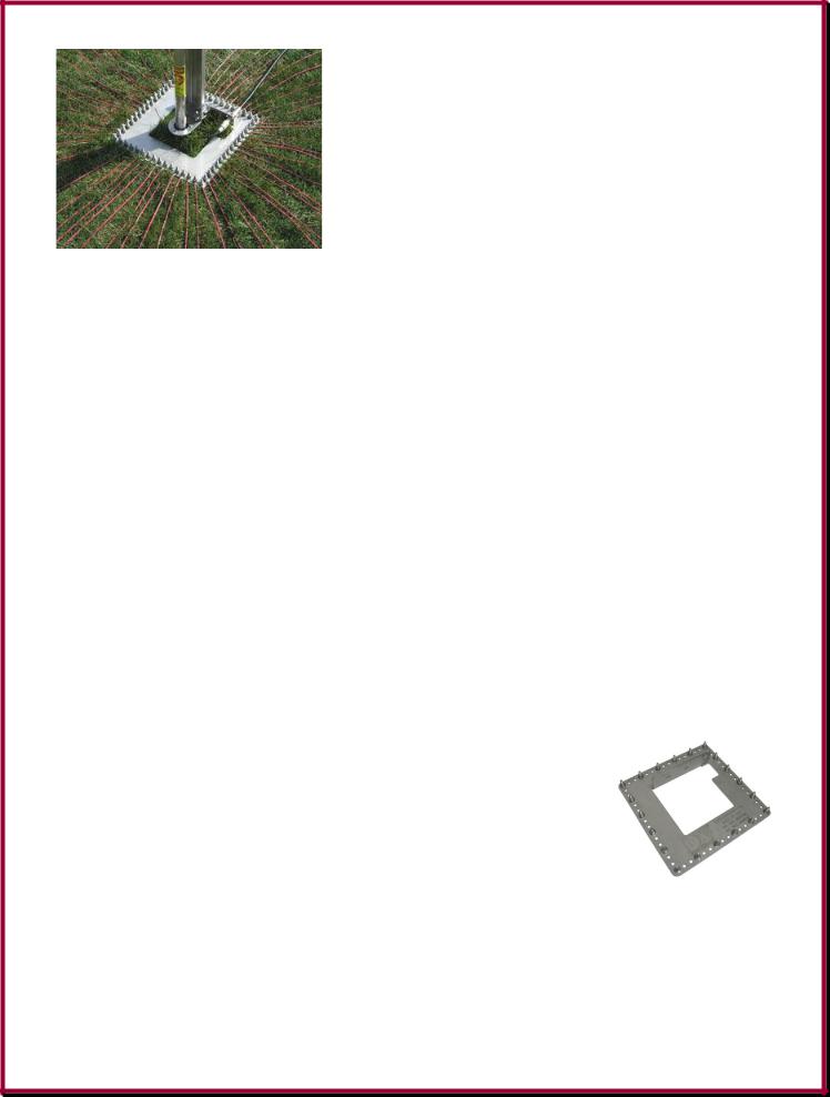
critical. They can be as short as one-eighth wavelength, but one-quarter wavelength radials on the lowest band of operation are typical. Long lasting and high-efficiency radial wire connections are easy to make using the stainless steel DX Engineering DXE-RADP-3 Radial Plate. Use the radial plate for a simple and neat way to install as many ground radial wires as you wish. Install 30 to 60 radials for higher performance using one or more DX Engineering radial wire kits. The relaxed black PVC insulated 14 gauge
stranded copper wire in our Radial Wire Kits is easy to handle and will last far longer than bare wire or wire mesh.
Why is such an extensive array of radial wires necessary? Simply put, it is the best way to increase your signal! The entire radial system must collect and carry currents equal to those flowing in the vertical section of the antenna. The ground-mounted vertical antenna needs many radial wires to prevent your RF power from being absorbed by the "lossy" ground. Even if your radials cannot run
- 14 -
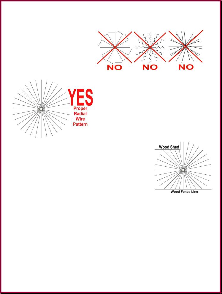
in all directions, you still get improved signals and prevent ground losses by installing as many symmetrically spaced radials as you can. You may use wires of any convenient length. Just run your radials in as many directions as you
can, straight away from the antenna base taking care not to zig-zag, bunch or cross over other radial wires. Radial by definition run in all directions, NOT parallel, NOT zig-zags, NOT crossing over each other. Run your radial wires in a spoke pattern.
Install your coaxial cable under the radials, at least a few inches in the ground, to minimize coupling between the radials and the coaxial cable shield. Additional decoupling the feedline can be effectively accomplished using a DX Engineering current choke instead of coiled coaxial cable, to reduce RF feedback, RFI.
To avoid damage from radial installation and for proper RF decoupling, the coaxial cable should be buried several inches under the radial system.
Performance of the antenna is directly proportional to the number and length of radials. Many short radials are better than a few long radials. The stainless steel DX Engineering DXE- RADP-3 Radial Plate makes it easy to attach long-lasting radial wire connections.
You don’t have to dig! Radial wires disappear under the grass when installed with DX Engineering steel or biodegradable anchor pins.
DO NOT bother to cut ground radials to resonant lengths because they are detuned by the ground. It is best to install many radials that are all the same length or lengths that fill a small irregular space.
Radial wires should run in all directions straight from the base feedpoint of the antenna. Ground radials cannot be bunched together for any length. If your radials cannot cover 360 degrees, that is okay. The antenna performs nearly the same with an equal number of radials squeezed into directions that cover smaller arcs.
Plan to install at least 20 radials using DX Engineering Radial Wire Kits. However, improved performance is accomplished using 30 to 60 radial wires.
- 15 -

|
Examples of properly installed radials |
K7CIE |
N8DOD |
N5RMM |
W0ZSP |
|
- 16 - |

Chapter 5 - Basic BTV Assembly |
|
Assembling Vertical Aluminum Antenna Sections & Element Clamps |
17 |
Hustler Base Assembly |
19 |
Hustler 4-BTV - Package Contents & Assembly |
20 |
Hustler 5-BTV - Package Contents & Assembly |
22 |
Six Blade Spider for the 4-BTV and 5-BTV only |
24 |
Three Blade Spider for the 5-BTV only |
24 |
80 Meter Resonator and Whip Installation for the 5-BTV and 6-BTV |
24 |
Hustler 6-BTV - Package Contents & Assembly |
25 |
Mating the Vertical Sections to the Base Section |
27 |
Installing Radials & Feedline on the Hustler Base |
28 |
Coax RF Choke |
29 |
Basic Tuning |
29 |
Assembling Vertical Aluminum Antenna Sections & Element Clamps
Note: DXE-P8A -Penetrox A Anti-Oxidant should be used between all antenna element sections. Penetrox is an electrical joint compound to affect a substantial electrical connection between metal parts such as telescoping aluminum tubing or other antenna pieces. It ensures high conductivity at all voltage levels by displacing moisture and preventing corrosion or oxidation
When assembling any telescoping aluminum tubing sections you should take the following steps:
1.Make sure the edges are smooth and not sharp. Deburring may be necessary, since burrs and shavings can occur on seams as well as edges. All surfaces need to be completely smooth to allow easy assembly of tubing sections.
Caution
Aluminum tubing edges can be very sharp.
Take precautions to ensure you do not get accidentally cut.
The raised particles and shavings that appear when the aluminum tubing is machined are referred to as burrs, and the process by which they are removed is known as deburring.
Deburring is a finishing method used in manufacturing. Aluminum tubing is machine cut on both ends and machine slit as needed. Although Hustler manufactured aluminum tubing is deburred, you should further assure that there are no ragged edges or protrusions.
Use the DXE-22166 Slim Grip Deburring Tool, or the DXE-22600 Deburring Tool with Extending Handle and Extra Blades for this operation.
2.Clean the inside of the aluminum tubing to clear out any dirt or foreign material that would cause the aluminum tubing sections to bind during assembly. Do not use any type of oil or general lubricant between the aluminum tubing sections. Oils or general lubricants can cause poor electrical connections for radio frequencies.
-17 -
3.Clean the outside of the aluminum tubing to clear any dirt or foreign material that would cause the clamps to malfunction during assembly.
4.The use of DXE-P8A Penetrox A is highly recommended. Penetrox A is an electrical joint compound which effects a substantial electrical connection between metal parts such as telescoping aluminum tubing or other antenna pieces. Using Penetrox A assures high conductivity at all voltage levels by displacing moisture and preventing corrosion or oxidation.
5.When assembling the aluminum tubing sections, ensure the area is clear of grass, dirt or other foreign material that could cause problems during assembly of the closely fitted telescoping sections.
Assemble the vertical sections in an area that is flat and has sufficient room for the length of the antenna during assembly.
Assembly is easier if the tubing sections are pre-marked. A dark color felt-tip marker works well.
Locate the hardware pack containing the element clamps.
Refer to the following 4-BTV, 5-BTV or 6-BTV assembly instructions, depending on your antenna, for element clamps, tubing and trap placement.
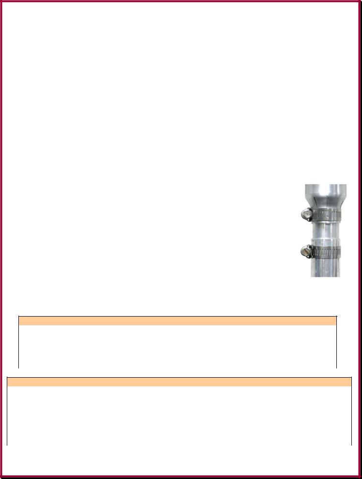
Slide all the clamps over each section before putting them together. You can lightly tighten the clamps just below the slits in each section to hold them until needed.
Align the clamp screws on each section to face the same direction.
At final assembly, body of the clamp should be positioned between the slits in the tubes and 1/8" from the edge of each tube as shown to the right.
Making sure dirt or grass does not adhere to the sections to be joined. The body of the element clamp is positioned between the slits and tighten securely.
The following charts show the suggested starting measurements for the 4/5-BTV and 6-BTV antennas. Note the charts show different measurements for various installation methods.
4-BTV and 5-BTV Approximate Starting Dimensions
Type of Installation |
A1 |
A2 |
B1 |
B2 |
C1 |
|
C2 |
D |
On a roof with 4 ft pipe and radials |
2-1/8" |
2-1/8" |
2" |
2" |
1-7/8" |
1-7/8" |
61-1/8" |
|
On metal tower w/radials dropped 45º |
2" |
2" |
2" |
2" |
1-1/8" |
|
1-1/8" |
61-1/8" |
Ground Mounted - No Radials |
0" |
0" |
1/2" |
1/2" |
1-1/16" |
1-1/16" |
62-1/8" |
|
Ground Mounted with Radials |
0" |
2" |
0" |
2" |
0" |
|
1-1/2" |
62-1/8" |
6-BTV Approximate Starting Dimensions
|
Type of Installation |
|
|
A1 |
|
|
A2 |
|
|
B1 |
|
|
B2 |
|
|
C1 |
|
|
C2 |
|
|
D1 |
|
|
D2 |
|
|
E |
|
|
On a roof with 4 ft pipe and |
|
|
2-1/8" |
|
|
2-1/8" |
|
|
2" |
|
|
2" |
|
|
1-7/8" |
|
|
1-7/8" |
|
|
1-1/2" |
|
|
1-1/2" |
|
|
1" |
|
|
|
|
|
|
|
|
|
|
|
|
|
|
|
|
|
|
|
|
|
||||||||||
|
radials |
|
|
|
|
|
|
|
|
|
|
|
|
|
|
|
|
|
|
|
|||||||||
|
|
|
|
|
|
|
|
|
|
|
|
|
|
|
|
|
|
|
|
|
|
|
|
|
|
|
|
|
|
|
Ground Mounted - No |
|
0" |
|
0" |
|
1-1/2" |
|
1-1/2" |
|
1-1/16" |
|
1-1/16" |
|
2" |
|
2" |
|
2" |
|
|||||||||
|
Radials |
|
|
|
|
|
|
|
|
|
|
||||||||||||||||||
|
|
|
|
|
|
|
|
|
|
|
|
|
|
|
|
|
|
|
|
|
|
|
|
|
|
|
|
|
|
|
Ground Mounted with |
|
|
0" |
|
|
2" |
|
|
0" |
|
|
2" |
|
|
0" |
|
|
1-1/2" |
|
|
0" |
|
|
2" |
|
|
1-1/2" |
|
|
|
|
|
|
|
|
|
|
|
|
|
|
|
|
|
|
|
|
|
||||||||||
|
Radials |
|
|
|
|
|
|
|
|
|
|
|
|
|
|
|
|
|
|
|
|||||||||
|
|
|
|
|
|
|
|
|
|
|
|
|
|
|
|
|
|
|
|
|
|
|
|
|
|
|
|
|
|
- 18 -
 Loading...