

Page 1

Hustler Z
Parts Manual
375535 Rev. 6/06
•••••••
Hustler Turf Equipment
•••••
P.O. Box 7000
•••
Hesston, Kansas
•
67062-2097
Page 2
WARNING:
The engi ne exhaust from this product
contains chemicals known to the Stat e
of California to cause cancer, birth
defects or other reproductive harm.
IMPORTANT: This engine is not equipped with a spark arrester muffler. It is a violation of California Public Resource Code
Section 4442 to use o r operate this eng ine on any fo r est-co vered, brush-covered, or grass-co vered unimpr oved land . Other
states or federal areas may have similar laws.
This spark ign i tion sy stem complies with Ca nad i an ICES-002.
The enc losed Engine Owner’s Manual is supplied fo r info rmation regarding the U.S. Environmental Protec tion Agency
(EPA) and the California Emission Control Regulation of emission syste ms, ma intenance and warranty.
Keep this Engine Ow ner’s Manual with your uni t. S hould the Engine Ow ner’s Manual become damaged or ill e gible,
repl ace immediately. Replacements ma y be ordere d per the informa ti on found in t he Product Informa t ion section o f
this manual.
Page 3

Chapter 1
General Information . . . . . . . . . . . . . . . . . . . . . . . . . . . . . . . . . . . . 1-1
Chapter 2 Contents
Rivet Nut Installation . . . . . . . . . . . . . . . . . . . . . . . . . . . . . . . . . . . . 2-2
Footrest Assembly . . . . . . . . . . . . . . . . . . . . . . . . . . . . . . . . . . . . . 2-3
Chapter 3 Contents
Hydraulic System Installation . . . . . . . . . . . . . . . . . . . . . . . . . . . . . 3-2
Chapter 4 Contents
Battery Installation. . . . . . . . . . . . . . . . . . . . . . . . . . . . . . . . . . . . . . 4-2
Deck Lift Assembly . . . . . . . . . . . . . . . . . . . . . . . . . . . . . . . . . . . . . 4-4
Steering and Park Brake Assembly (Centering Damper) . . . . . . . . 4-6
Pump Belt and Pulleys Installation . . . . . . . . . . . . . . . . . . . . . . . . . 4-14
Chapter 5 Contents
Kawasaki Engine Installation . . . . . . . . . . . . . . . . . . . . . . . . . . . . . 5-2
Honda Engine Installation . . . . . . . . . . . . . . . . . . . . . . . . . . . . . . . . 5-6
Kohler Engine Installation . . . . . . . . . . . . . . . . . . . . . . . . . . . . . . . . 5-10
Fuel System Installation . . . . . . . . . . . . . . . . . . . . . . . . . . . . . . . . . 5-14
Fuel System Installation . . . . . . . . . . . . . . . . . . . . . . . . . . . . . . . . . 5-16
Instrument Panel Assembly . . . . . . . . . . . . . . . . . . . . . . . . . . . . . . 5-18
Electrical Schematic - Kawasaki (783894) . . . . . . . . . . . . . . . . . . . 5-20
Electrical Schematic - Honda (787200). . . . . . . . . . . . . . . . . . . . . . 5-22
Electrical Schematic - Kohler (788000). . . . . . . . . . . . . . . . . . . . . . 5-24
Table of Contents
Chapter 6 Contents
Front Wheel Assembly . . . . . . . . . . . . . . . . . . . . . . . . . . . . . . . . . . 6-2
Front Wheel Breakdown—747782 . . . . . . . . . . . . . . . . . . . . . . . . . 6-4
Optional Semi-Pneumatic Tire/Wheel—789537 . . . . . . . . . . . . . . . 6-5
Drive Wheel Assembly Installation . . . . . . . . . . . . . . . . . . . . . . . . . 6-6
Anti-Rollover Wheel Assembly . . . . . . . . . . . . . . . . . . . . . . . . . . . . 6-7
Chapter 7 Contents
72" Deck Assembly . . . . . . . . . . . . . . . . . . . . . . . . . . . . . . . . . . . . . 7-2
72" Deck Pulley Assembly . . . . . . . . . . . . . . . . . . . . . . . . . . . . . . . 7-4
60" Deck Assembly . . . . . . . . . . . . . . . . . . . . . . . . . . . . . . . . . . . . . 7-8
60" Deck Pulley Assembly . . . . . . . . . . . . . . . . . . . . . . . . . . . . . . . 7-10
52" Deck Assembly . . . . . . . . . . . . . . . . . . . . . . . . . . . . . . . . . . . . . 7-14
52" Deck Pulley Assembly . . . . . . . . . . . . . . . . . . . . . . . . . . . . . . . 7-16
Spindle Assembly - 350595K . . . . . . . . . . . . . . . . . . . . . . . . . . . . . 7-19
Spindle Assembly - 796235 . . . . . . . . . . . . . . . . . . . . . . . . . . . . . . 7-20
Chapter 8 Contents
Deck Installation . . . . . . . . . . . . . . . . . . . . . . . . . . . . . . . . . . . . . . . 8-2
Deck Belt Routing and Tensioning . . . . . . . . . . . . . . . . . . . . . . . . . 8-4
Seat Installation. . . . . . . . . . . . . . . . . . . . . . . . . . . . . . . . . . . . . . . . 8-6
Chapter 9 Contents
375535 6/06 c-1
Page 4

Tractor Decals . . . . . . . . . . . . . . . . . . . . . . . . . . . . . . . . . . . . . . . . 9-2
72" and 60" Deck Decals . . . . . . . . . . . . . . . . . . . . . . . . . . . . . . . . 9-4
52" Deck Decals. . . . . . . . . . . . . . . . . . . . . . . . . . . . . . . . . . . . . . . 9-5
Chapter 10 Contents
72" and 60" Mulch Kits . . . . . . . . . . . . . . . . . . . . . . . . . . . . . . . . . . 10-2
72" Mulch Kit–352419 . . . . . . . . . . . . . . . . . . . . . . . . . . . . . . . . . . 10-3
60" Mulch Kit–352427 . . . . . . . . . . . . . . . . . . . . . . . . . . . . . . . . . . 10-4
52" Mulch Kit–344929 . . . . . . . . . . . . . . . . . . . . . . . . . . . . . . . . . . 10-5
52" Mulch Kit–352435 . . . . . . . . . . . . . . . . . . . . . . . . . . . . . . . . . . 10-6
Chapter 11 Contents
Maintenance & Adjustments Safety Precautions . . . . . . . . . . . . . . 11-3
Maintenance . . . . . . . . . . . . . . . . . . . . . . . . . . . . . . . . . . . . . . . . . . 11-7
Adjustments . . . . . . . . . . . . . . . . . . . . . . . . . . . . . . . . . . . . . . . . . . 11-15
Index. . . . . . . . . . . . . . . . . . . . . . . . . . . . . . . . . . . . . . . . . . . . . . . . . . . . . . . . i-1
c-2 375565 6/06
Page 5

Chapter 1
General Information
This Manual covers Hustler Z models 926667 24/60, 926675 24/60, 926881 23/52, 926915 23/60, 926923 23/60,
926931 25/60, 926949 25/60, 926964 25/72, 927111 27/60, 927160 27/72, and 927475 27/52.
Frequently Ordered Parts
PART NO. DESCRIPTION
027912 LUBRIZOL 7 OZ. BOTTLE
027920 LUBRIZOL 10 OZ. BOTTLE
768341 HYDRAULIC OIL FILTER
781443 PUMP DRIVE BELT
784207 B-SECTION BELT, 72" DECK
781310 B-SECTION BELT, 60" DECK
782292 B-SECTION BELT, 52" DECK
068478 FUEL FILTER
785261 MAIN AIR FILTER ELEMENT
785279 SAFETY AIR FILTER ELEMENT
772079 KAWASAKI ENGINE OIL FILTER
785634 HONDA ENGINE OIL FILTER
747303 KOHLER ENGINE OIL FILTER
795526 17.86"-H-F-CW BLADE
795252 20.95"-H-F-CW BLADE
795260 23.86"-H-F-CW BLADE
Service Literature
PART NO. DESCRIPTION
375527 HUSTLER Z OWNER’S MANUAL
742684 KOHLER ENGINE MANUAL
778423 KAWASAKI 19/23HP OWNERS MANUAL
785642 HONDA 18/20/24 OWNERS MANUAL
Note: When ordering parts, you must use the part number as shown for each part, not the index number. Always give
the model and serial number to your parts and service representative.
Note: Items sold in bulk such as seals and hoses are sold by the foot.
Using this manual
Illustrations used were current at the time of printing, but subsequent production changes may cause your machine to
vary slightly in detail. Excel Industries, Inc. reserves the right to redesign and change the machine as deemed necessary, without notification. If a change has been made to your machine which is not reflected in this parts manual, see
your Hustler dealer for current information and parts.
375535 6/06 1-1
Page 6

Hardware Description Codes & Abbreviations
The following codes are used throughout this parts manual. Refer to this list when ordering parts.
ABBREVIATION DESCRIPTION
CB CARRIAGE BOLT
CE CLEVIS PIN
CP COTTER PIN
CS CAP SCREW
CW CUP WASHER
FDRW FENDER WASHER
FW FLAT WASHER
HX HEX HEAD
LW L O CK WASHER
MB MACHINE BUSHING
MS MACHINE SCREW
NT NUT
SC SELF TAPPING CAP SCREW
SH SOCKET HEAD
SB SHOULDER BOLT
SS SET SCREW
Standard Torques
The following chart lists the standard torque values for the threaded fasteners found in this manual. Torque all cap
screws, nuts and set screws to these values unless a different torque is shown in the Notes section next to the fastener
SIZE FT-LBS NM SIZE FT-LBS NM
.250 8.2 11.1 M3 1 1.3
.312 17 23 M4 2.2 3
.375 30 40 M5 4.5 6.1
.438 48 65 M6 7.7 10.4
.500 73 99 M8 18.5 25
.562 105 143 M10 37 50
.625 145 200 M12 64 87
.750 260 350 M16 160 215
.875 420 565 M20 320 435
1.00 625 850 M24 555 750
NOTE:
Loctite 592 to be used on all pipe threads.
Lubricate all grease zerks.
1-2 375535 6/06
Page 7

Chapter 2 Contents
Rivet Nut Installation . . . . . . . . . . . . . . . . . . . . . . . . . . . . . . . . . . . . . 2-2
Foot Rest Assembly. . . . . . . . . . . . . . . . . . . . . . . . . . . . . . . . . . . . . . 2-3
375535 6/06 2-1
Page 8
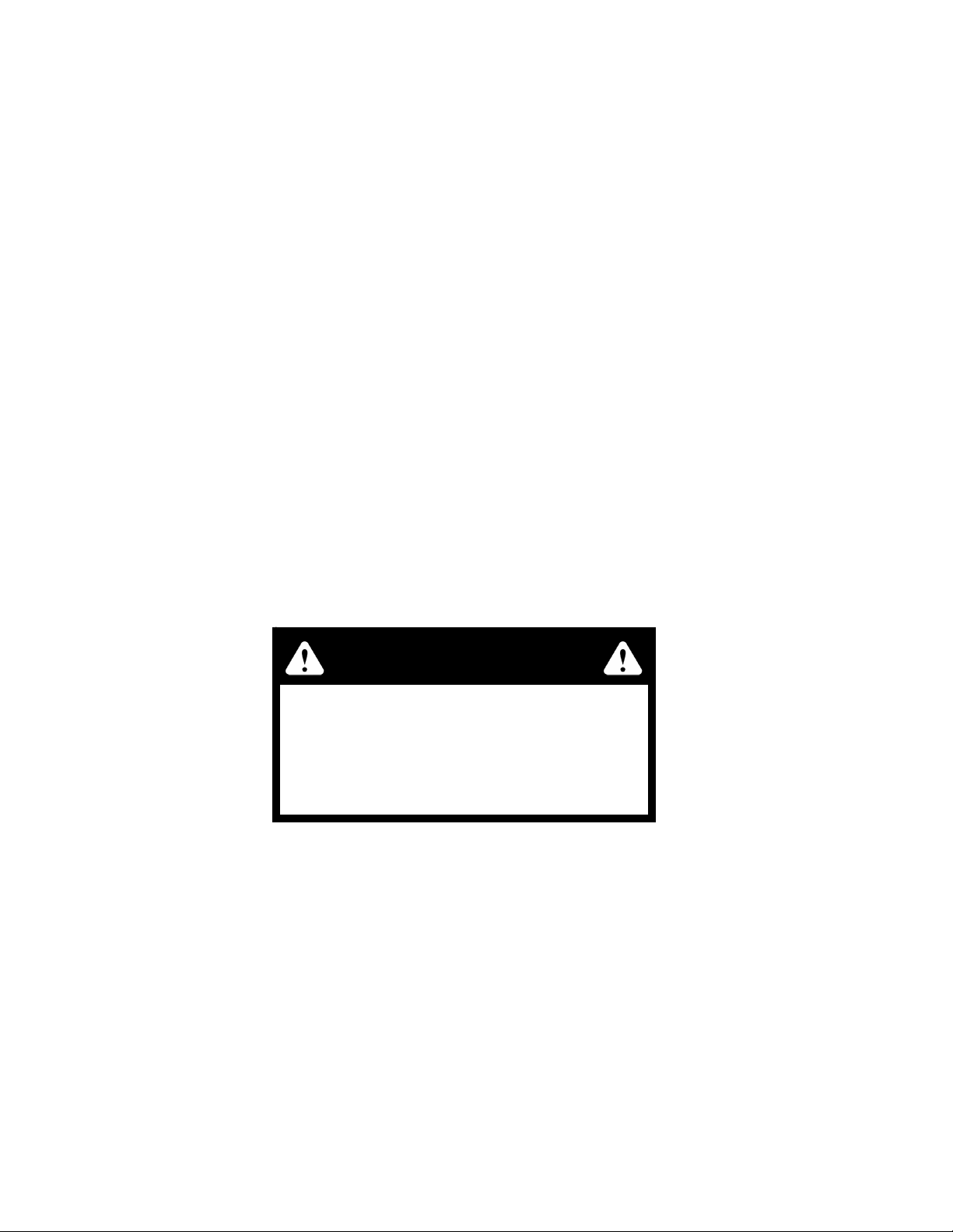
Rivet Nut Installation
1
2
INDEX
NO.
1 545285 349605 1 TRACTOR FRAME (60")
2 N/A 808493 4 3/8-16 THREAD RIVET NUT
SERVICE
PART NO.
545350 347534 1 TRACTOR FRAME (52")
545806 362657 1 TRACTOR FRAME (72”)
MFG.
PART NO.
QTY DESCRIPTION
NOTES:
2-2 375535 6/06
Page 9
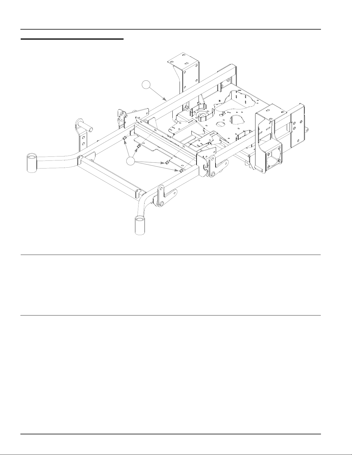
Footrest Assembly
1
2
4
5
6
3
5
1
7
INDEX
NO.
1 359547 359547 2 STEP TREAD
2 348276 348276 1 FLOOR
2
3
3 305615 305615 2 PLATFORM STEP TREAD
4 086660 086660 2 NT .375-16 HX LK NY
5 767954 767954 4 FW .406 X .812 X .060 SAE HD ZN
6 781880 781880 2 RUBBER BUMPER
7 052860 052860 2 CS .375-16 X 1.250 HX G5 ZN
SERVICE
PART NO.
395533 395533 1 FLOOR
MFG.
PART NO.
QTY DESCRIPTION
NOTES:
1. Do not tighten, Item 2 (348276/395533 Floor) must be able to pivot on
these bolts.
2. Used on mowers with serial number prior to 03082000.
3. Used on mowers with serial number 03082000 and higher.
375535 6/06 2-3
Page 10

2-4 375535 6/06
Page 11

Chapter 3 Contents
Hydraulic System Installation. . . . . . . . . . . . . . . . . . . . . . . . . . . . . . . 3-2
375535 6/06 3-1
Page 12
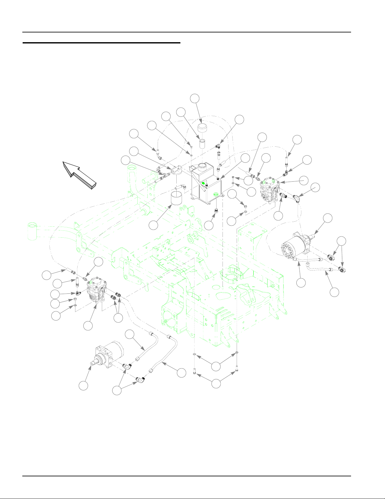
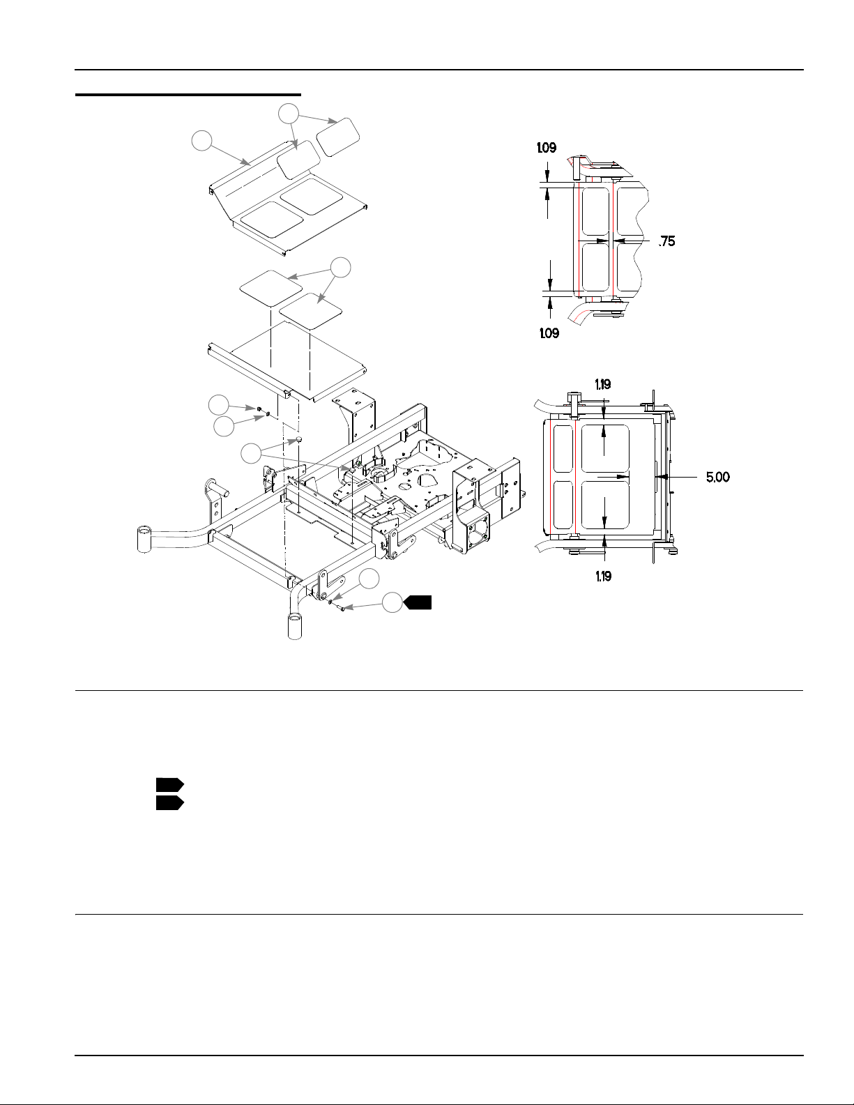
Hydraulic System Installation
2
1
16
15
31
4
3
17
19
5
20
18
17
FRONT
30
18
17
10
11
6
10
14
20
29
9
28
23
11
7
21
8
22
12
24
26
25
12
11
27
13
24
3-2 375535 6/06
Page 13

Hydraulic System Installation
ITEM
NO.
1 768515 768515 2 FW .281 X .625 X .051/.080 HD ZN/YL
2 055947 055947 2 CS .250-20 X .500 HX G5 ZN
3 032771 032771 1 STRAINER
4 032763 032763 1 BREATHER CAP
5 349860 349860 1 RESERVOIR
6 034272 034272 4 NT .312-18 HX G5 ZN
7 768523 768523 4 FW .343 X .687 X .051/.080 HD ZN/YL
8 781062 781062 1 HYDRO-GEAR PUMP, BDP-10A-300
9 781047 781047 1 HYDRO-GEAR PUMP BDP-10A-400
10 041707 041707 4 NT .437-14 HX G5 ZN
11 704742 704742 8 FW .453 X .812 X .060 ZN
12 781054 781054 2 ROSS/PARKER WHEEL MOTOR, MB-15
13 705186 705186 4 CS .437-14 X 1.375 HX G5 ZN
14 768341 768341 1 FILTER ELEMENT
15 768333 768333 1 FILTER HEAD
16 781575 N/A 1 -6STR -6 90°, PUSHLOC HOSE 4.75"
17 763946 N/A 3 90°, -6 O-RING/-6 JIC FITTING
18 778985 N/A 2 -6STR -6 90°, PUSHLOC HOSE, 13.00"
19 781591 N/A 1 -6STR -6 90°, PUSHLOC HOSE, 15.00"
20 779132 N/A 2 STR-6MORB/-6JIC FITTING
21 781559 N/A 1 45°, -8MORB/-8MSL FITTING
22 781542 N/A 1 90°,-8MORB/-8MSL FITTING
23 781658 N/A 1 STR-8-MORB/HEX PLUG
24 781526 N/A 4 90°, -10MORB/-8MSL FITTING
25 781500 N/A 1 RIGHT LOOP/RP-BM HYDRO TUBE
26 781492 N/A 1 RIGHT LOOP/LP-TM HYDRO TUBE
27 781484 N/A 1 LEFT LOOP/RP-BM HYDRO TUBE
28 781476 N/A 1 LEFT LOOP/LP-TM HYDRO TUBE
29 781534 N/A 2 STR-8MORB/-8MSL FITTING
30 781518 N/A 1 -6STR -6STR PUSHLOC HOSE, 9.00"
31 763953 N/A 1 -6 O-RING/-6JIC/6JIC T FITTING
SERVICE
PART NO.
N/A 781469 1 MMZ HYDRAULIC KIT (INCLUDES 16-31)
MFG.
PART NO.
QTY DESCRIPTION
NOTES:
1. Add 3.5 oz. Lubrizol® (027912) to new system or when hydraulic oil is
changed (see Owner’s Manual).
2. Hydraulic system capacity is 5 US quarts. Fill reservoir to within 1" of top
of Item 3 (032771 Strainer)
375535 6/06 3-3
Page 14

Note:
HYDRAULIC SYSTEM CHARGING PROCEDURE
1. Set handles in the neutral position.
2. Start engine at idle.
3. Let run for a minimum of 30 seconds.
4. Stroke handles to forward position.
5. If motors do not turn in 15 seconds return handles to neutral and
repeat step 3 and 4 (one time).
6. If motors do not turn after second attempt, shut off the engine
and check for oil at the pump.
7. Increase throttle to half speed and work handles through forward
and reverse position until the motor operates smoothly
throughout the entire speed range.
Seal Kit for hydraulic pump; 727756 (BDP10 Overhaul Seal Kit)
3-4 375535 6/06
Page 15

Chapter 4 Contents
Battery Installation . . . . . . . . . . . . . . . . . . . . . . . . . . . . . . . . . . . . . . . 4-2
Deck Lift Assembly . . . . . . . . . . . . . . . . . . . . . . . . . . . . . . . . . . . . . . 4-4
Steering and Brake Assembly (Centering Damper). . . . . . . . . . . . . . 4-6
Steering and Park Brake Assembly (With Anti Reverse). . . . . . . . . 4-10
Pump Belt and Pulley Installation . . . . . . . . . . . . . . . . . . . . . . . . . . 4-14
375535 6/06 4-1
Page 16
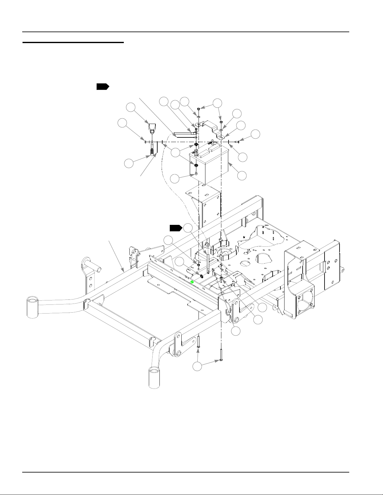
Battery Installation
BLACK WIRE,
1
PART OF WIRE
HARNESS
2
3
1
5
1
6
5
7
8
RED WIRE,
PART OF WIRE
HARNESS
TRACTOR
FRAME
9
4
8
1
3
11
14
9
10
12
11
5
13
4-2 375535 6/06
Page 17

Battery Installation
INDEX
NO.
1 024927 024927 2 NT .250-20 HX GR.5 ZN
2 771428 771428 1 RED BATTERY CABLE BOOT
3 768820 768820 1 BATTERY GROUND CABLE
4 744276 744276 1 POSITIVE BATTERY CABLE
5 768523 768523 3 FW .343 X .687 X .051/.080 HD ZN/YL
6 058776 058776 2 NT .312-18 HX NL ZN
7 348417 348417 1 BATTERY CLAMP STRAP
8 055939 055939 2 CS .250-20 X .750 HX G5 ZN
9 029868 029868 4 LW .250 INT-EXT TOOTH ZN
10 740696 740696 1 BATTERY
11 034272 034272 2 NT .312-18 HX G5 ZN
12 034280 034280 1 CS .312-18 X .750 HX G5 ZN
13 779850 779850 2 CB .312-18 X 3.00 FUL ZN
14 029876 029876 1 LW .312 INT-EXT TOOTH ZN
SERVICE
PART NO.
MFG.
PART NO.
QTY DESCRIPTION
NOTES:
1. When performing service on mower, disconnect battery ground cable
and black wire of harness and do not reconnect to battery until engine is
ready to be started. See Owners Manual.
375535 6/06 4-3
Page 18
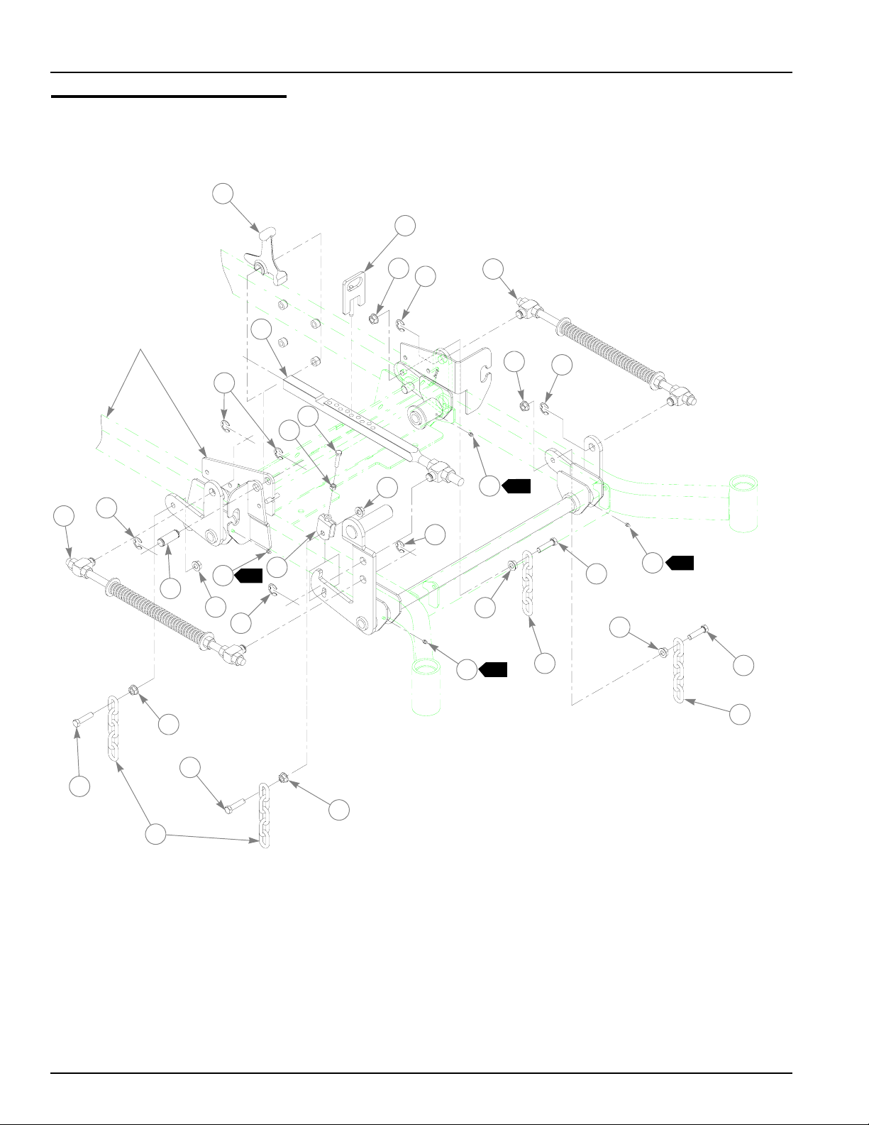
Deck Lift Assembly
1
2
4
5
TRACTOR
FRAME
5
6
7
10
4
3
5
12
11
4
5
13
1
5
10
10
4
6
4
1
1
5
1
8
9
10
4
8
4
14
8
4
9
4-4 375535 6/06
9
Page 19

Deck Lift Assembly
ITEM
NO.
1 348318 348318 1 STOP HANDLE
2 600437 600437 1 DECK HEIGHT PIN - 1/2" DIA
2
{
3 783001 783001 1 DECK LIFT INDICATOR SUBASSEMBLY
4 704643 704643 8 NT .437-14 HX FLG ZN
5 781294 781294 7 CLIP E, 1.00 X .625 X .050
6 782995 782995 2 DECK LIFT SPRING SUBASSEMBLY
7 781229 781229 1 CE .750 X 2.25 X 1.75 HEADLESS
8 055749 055749 3 CS .437-14 X 1.750 HX G5 ZN
9 348391 348391 4 DECK LIFT CHAIN
10 015495 015495 4 STRAIGHT GREASE FITTING
11 034272 034272 1 NT .312-18 HX G5 ZN
12 756270 756270 1 CS .312-18 X 1.50 FUL THR GR5 ZN
13 348458 348458 1 DECK LEVELER YOKE
14 781831 781831 1 CS .437-14 X 1.750 FUL THD G5 ZN
SERVICE
PART NO.
348284 N/A 1 HEIGHT ADJ STOP - 3/8" DIA
MFG.
PART NO.
QTY DESCRIPTION
NOTES:
1. Apply grease to zerks (see owner’s manual).
2. Verify pin diameter prior to ordering replacement part. For mowers with
3/8" diameter pins, order 348284; for mowers with 1/2" pins, order
600437. For replacement purposes, item 3 includes item 2 with 1/2"
diameter.
375535CE 6/06 4-5
Page 20
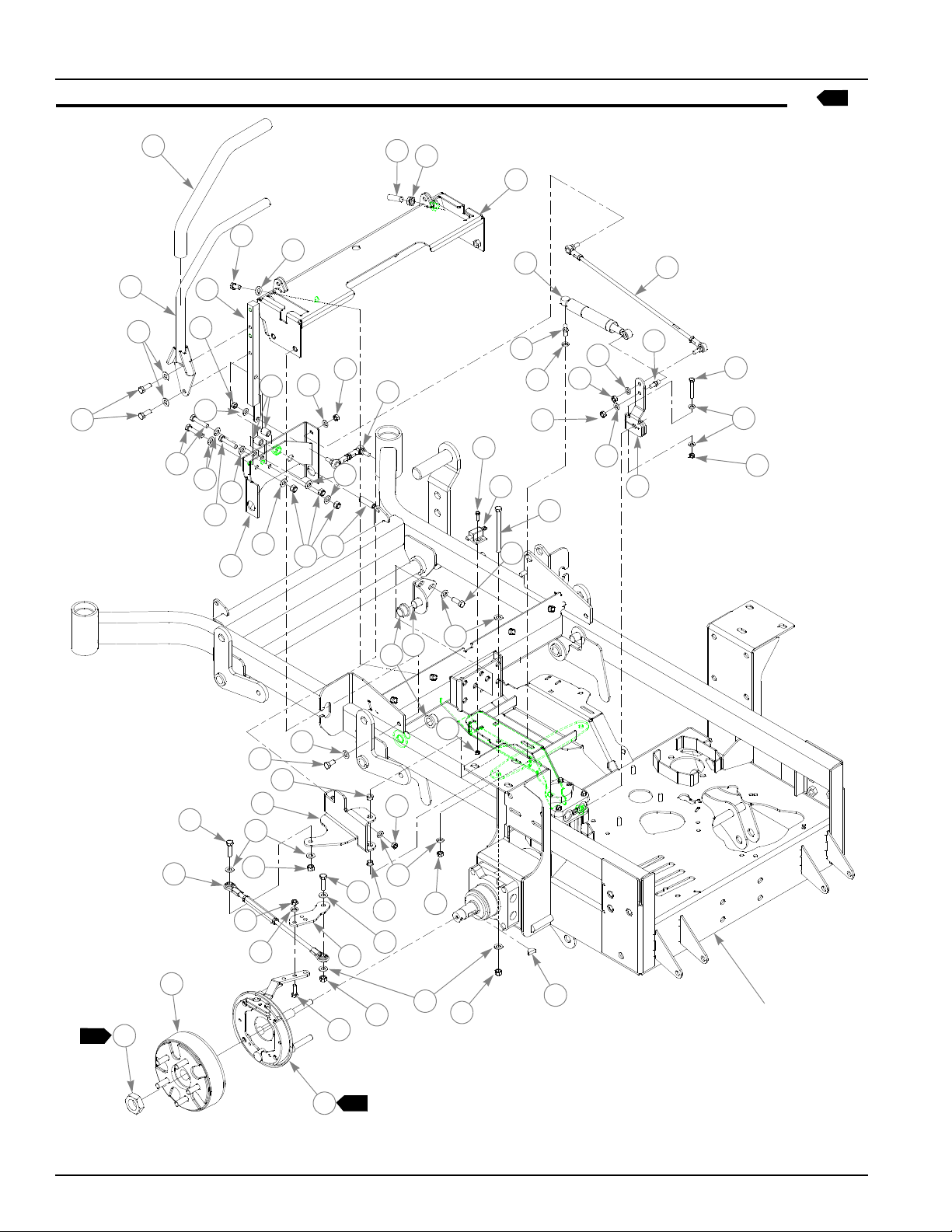
Steering and Park Brake Assembly (Centering Damper)
6
1
10
2
3
4
8
6
7
5
3
3
5
9
3
14
3
6
7
3
11
15
16
11
12
17
18
13
4
20
21
7
30
38
19
7
6
21
22
23
7
25
24
3
26
27
3
10
36
35
28
40
31
1
39
30
29
3
28
36
7
33
3
34
29
37
6
7
30
3
15
41
TRACTOR
FRAME
32
2
4-6 375535 6/06
Page 21

Steering and Park Brake Assembly (Centering Damper)
ITEM
NO.
1 781260 N/A 2 STEERING BAR GRIP
2 348755 348755 2 STEERING BAR
5
3 767954 767954 48 FW .406 X .812 X .060 SAE HD ZN
4 036244 036244 10 CS .375-16 X 1.000 HX G5 ZN
5 705178 705178 6 CS .375-16 X 1.750 HX G5 ZN
6 041152 041152 8 NT .312-24 HX ZN
7 768523 768523 18 FW .343X .687 X .051/.080 HD ZN/YL
8 348946 348946 2 STEERING ARM MOUNT
9 348888 348888 1 STEERLEVER SUPPORT LH
10 055822 055822 8 CS .375-16 X .750 HX G5 ZN
11 781716 781716 4 SS .500-13 X 1.75 SH ZN
12 053199 053199 2 NT .500-13 HX JAM ZN
13 348987 348987 1 STEERING CONTROL PANEL
14 348862 348862 4 STEERLEVER BUSHING
15 086660 086660 8 NT .375-16 HX LK NY
16 781583 781583 2 BRAKE ROD ASSEMBLY
17 063198 063198 4 CS 10-24 X .750 HXFLK ZN
18 781211 781211 2 PUSH BUTTON SWITCH
19 781286 781286 2 PUMP ROD ADJUSTER ASSEMBLY
20 783696 783696 2 CENTERING DAMPER
21 781922 781922 4 DAMPER BALL STUD
22 704163 704163 2 CS .250-20 X 2.00 HX G5 ZN
23 768515 768515 4 FW .281 X .625 X .051/.080 HD ZN/YL
24 068551 068551 2 NT .250-20 HX NL ZN
25 367557 367557 2 PUMP ARM
26 348797 348797 2 ADJUSTABLE PIVOT
27 781153 781153 4 BUSHING
28 005116 005116 4 CS .375-16 X 1.375 HX G5 ZN
29 054502 054502 4 NT .375-16 HX GRD 5 ZN
30 034272 034272 8 NT .312-18 HX G5 ZN
31 781765 781765 2 BRAKE DRUM-HUB ASSEMBLY
32 781112 781112 1 BRAKE ASSEMBLY
3
4
33 036236 036236 4 CS .312-18 X 1.000 HX G5 ZN
34 350272 350272 2 BRAKE ARM EXTENSION
35 350330 350330 1 L.S. BRAKE PIVOT ARM
36 765339 765339 4 BUSHING
37 059832 059832 4 NT #10-24 HX NL ZN
38 782979 782979 2 CS .375-16 X 4.75 HX G5 ZN
39 065516 N/A 2 ROSS CASTLE NUT
40 350397 350397 2 BRAKE LINK TURNBUCKLE
41 064337 N/A 2 ROSS KEY
SERVICE
PART NO.
348714 348714 1 STEERLEVER SUPPORT RH
781351 781351 1 BRAKE ASSEMBLY
350264 350264 1 R.S. BRAKE PIVOT ARM
MFG.
PART NO.
QTY DESCRIPTION
NOTES:
375535 6/06 4-7
Page 22

1. Torque to 350-375 ft.-lbs. Included with wheel motor.
2. Torque brake assembly mounting bolts to 100 ft.-lbs.
3. 781112 used on left wheel.
4. 781351 used on right wheel.
5. Includes item 1 (781260).
6. Used on tractors with serial number 03012522 and higher.
4-8 375535 6/06
Page 23

This page intentionally left blank.
375535 6/06 4-9
Page 24
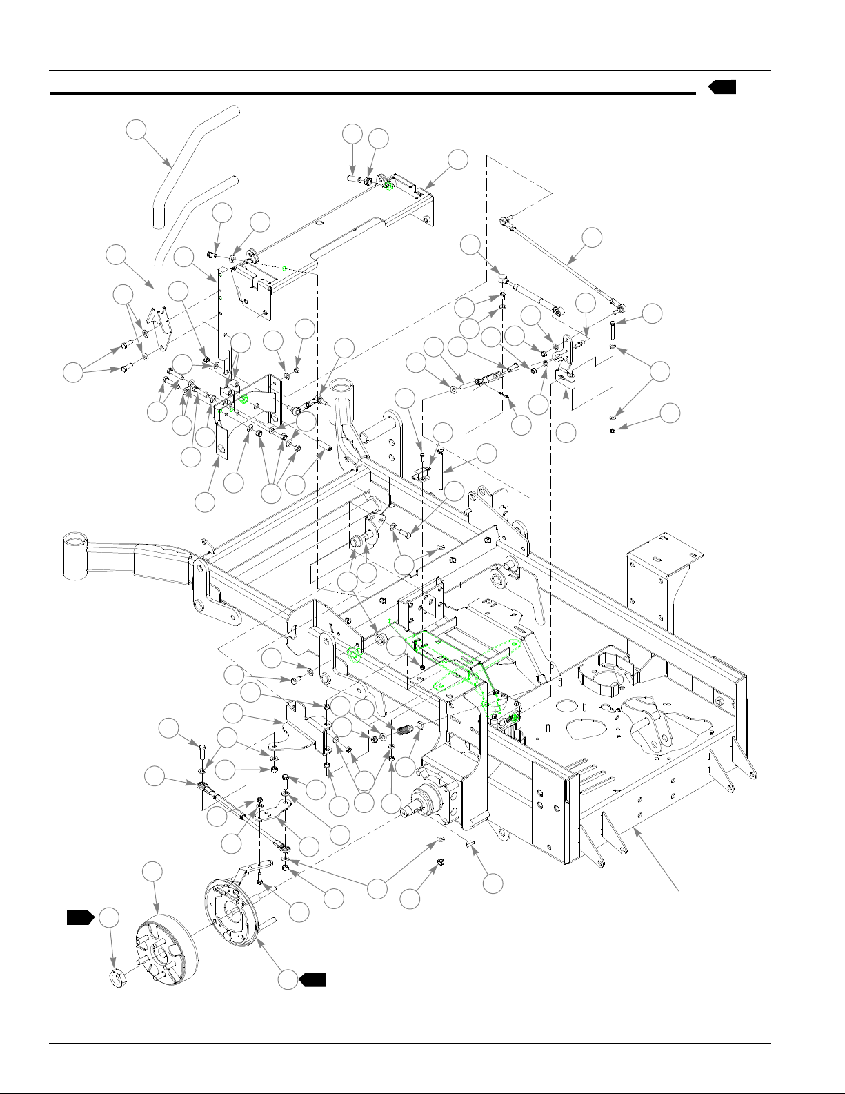
Steering and Park Brake Assembly (With Anti Reverse)
5
1
10
2
3
4
8
6
7
5
3
3
5
9
3
14
3
6
7
3
11
15
16
11
12
20
13
28
24
22
25
26
27
23
24
7
33
18
17
3
21
43
4
7
6
7
19
3
29
30
41
6
7
40
3
33
3
15
46
TRACTOR
FRAME
3
10
39
38
31
45
34
1
44
3
32
33
7
36
3
42
31
39
3
37
32
35
2
4-10 375535 6/06
Page 25

Steering and Park Brake Assembly (With Anti Reverse)
ITEM
NO.
1 781260 781260 2 STEERING BAR GRIP
2 348755 348755 2 STEERING BAR
3 767954 767954 48 FW .406 X .812 X .060 SAE HD ZN
4 036244 036244 10 CS .375-16 X 1.000 HX G5 ZN
5 705178 705178 6 CS .375-16 X 1.750 HX G5 ZN
6 041152 041152 8 NT .312-24 HX ZN
7 768523 768523 18 FW .343X .687 X .051/.080 HD ZN/YL
8 348946 348946 2 STEERING ARM MOUNT
9 348888 348888 1 STEERLEVER SUPPORT LH
10 055822 055822 8 CS .375-16 X .750 HX G5 ZN
11 781716 781716 4 SS .500-13 X 1.75 SH ZN
12 053199 053199 2 NT .500-13 HX JAM ZN
13 348987 348987 1 STEERING CONTROL PANEL
14 348862 348862 4 STEERLEVER BUSHING
15 086660 086660 8 NT .375-16 HX LK NY
16 781583 781583 2 BRAKE ROD ASSEMBLY
17 350413 350413 2 NEUTRAL STOP YOKE ASSEMBY
18 076745 076745 2 CE .375 X 1.125 .15 X .968 ZN
19 760199 760199 2 CP .125D X .750 LG ZN
20 063198 063198 4 CS 10-24 X .750 HXFLK ZN
21 781211 781211 2 PUSH BUTTON SWITCH
22 781286 781286 2 PUMP ROD ADJUSTER ASSEMBLY
23 781088 781088 2 DAMPER
24 781922 781922 4 DAMPER BALL STUD
25 704163 704163 2 CS .250-20 X 2.00 HX G5 ZN
26 768515 768515 4 FW .281 X .625 X .051/.080 HD ZN/YL
27 068551 068551 2 NT .250-20 HX NL ZN
28 350454 350454 1 L.S PUMP ARM
29 348797 348797 2 ADJUSTABLE PIVOT
30 781153 781153 4 BUSHING
31 005116 005116 4 CS .375-16 X 1.375 HX G5 ZN
32 054502 054502 4 NT .375-16 HX GRD 5 ZN
33 034272 034272 8 NT .312-18 HX G5 ZN
34 781765 781765 2 BRAKE DRUM-HUB ASSEMBLY
35 781112 781351 1 BRAKE ASSEMBLY
3
4
36 036236 036236 4 CS .312-18 X 1.000 HX G5 ZN
37 350272 350272 2 BRAKE ARM EXTENSION
38 350330 350330 1 L.S. BRAKE PIVOT ARM
39 765339 765339 4 BUSHING
40 059832 059832 4 NT #10-24 HX NL ZN
41 018861 018861 2 COMPRESSION SPRING
42 718791 718791 2 NT .375-24 NYLOCK ZN
43 782979 782979 2 CS .375-16 X 4.75 HX G5 ZN
44 065516 N/A 2 ROSS CASTLE NUT
45 350397 350397 2 BRAKE LINK TURNBUCKLE
SERVICE
PART NO.
348714 348714 1 STEERLEVER SUPPORT RH
348979 348979 1 R.S PUMP ARM
781351 781112 1 BRAKE ASSEMBLY
350264 350264 1 R.S. BRAKE PIVOT ARM
MFG.
PART NO.
QTY DESCRIPTION
375535 6/06 4-11
Page 26

ITEM
NO.
46 064337 N/A 2 ROSS KEY
SERVICE
PART NO.
MFG.
PART NO.
QTY DESCRIPTION
NOTES:
1. Torque to 350-375 ft.-lbs. Included with wheel motor.
2. Torque brake assembly mounting bolts to 100 ft.-lbs.
3. 781112 used on left wheel.
4. 781351 used on right wheel.
5. Used on tractors with serial prior to 03012522.
4-12 375535 6/06
Page 27

This page intentionally left blank.
375535 6/06 4-13
Page 28
Pump Belt and Pulleys Installation
1
2
23
2
4
33
13
LOCATION OF
RUBBER BUMPER
SEE NOTE 5
25
31
30
24
25
29
26
28
34
27
TRACTOR
FRAME
34
37
38
39
3
3
6
8
7
10
36
9
13
10
9
1
2
3
4
1
5
6
12
8
10
11
7
3
6
14
10
1
24
25
13
2
7
SEE NOTE 6
18
2
19
2
28
32
35
25
31
5
4-14 375535 6/06
15
20
16
17
21
22
Page 29

Pump Belt and Pulleys Installation
7 5
7 6
INDEX
NO.
1 779876 779876 1 ENGINE SC SINGLE PULLEY
2 212076 212076 1 KEY 1/4 SQ X 1.50 LONG
4
3 787366 787366 1 WARNER CLUTCH
4 783829 783829 1 FW .460 X 1.750 X .250 ZNYC
5 785659 785659 1 CS .437-20 X 2.50 HX G5 ZNYC
6 083196 083196 4 SS .312-18 X .750 SQ-HD ZN
7 768127 768127 2 KEY 5MM X 30MM RADIUS ENDS
8 325308 325308 2 PULLEY & FAN
9 008193 008193 2 NT .500-13 HX G5 ZNYC
10 767962 767962 4 FW .531 X 1.063 X .090 SAE HD ZN
11 016527 016527 2 CS .500-13 X 1.00 HX G5 ZNYC
12 366765 366765 1 CLUTCH ANCHOR ANGLE
13 784918 784918 2 RUBBER BUMPER
14 349761 349761 1 PUMP IDLER ARM
15 015495 015495 1 STRAIGHT GREASE FITTING
16 025296 025296 1 FW .760 X 1.625 X .08 ZN
17 061101 061101 1 NT .750-10 HX NL ZN
18 781856 781856 1 IDLER PULLEY
19 028118 028118 1 FW .62 X 1.00 X.134 ZN
20 794446 794446 1 CS .625-11 X 1.50 HX G5 ZN
21 781302 781302 1 IDLER SPRING
22 781443 781443 1 A-SEC PUMP IDLER BELT
23 N/A N/A 1 OGURA GT2 CLUTCH (787408)
24 036244 N/A 1 CS .375-16 X 1.000 HX G5 ZN
25 767954 N/A 2 FW .406 X .812 X .060 SAE HD ZN
26 055939 N/A 1 CS .250-20 X .750 HX G5 ZN
27 362392 N/A 1 CLUTCH ANCHOR BRACKET
28 778738 N/A 1 .312 WIRING CLAMP
29 768515 N/A 1 FW .281 X .625 X .051/.080 HD ZN/YL
30 024927 N/A 1 NT .250-20 HX GR.5 ZN
31 054502 N/A 1 NT .375-16 HX GRD 5 ZN
32 366823 N/A 1 CLUTCH ANCHOR BRACKET
33 778217 N/A 1 CS .437-20 X 2.250 G5 ZNYC
34 748681 N/A 1 GM .75 X 1.35 X 1.06 X .18 GROMMET
35 N/A N/A 1 OGURA GT3 CLUTCH (786228)
36 791251 791251 1 HARNESS, CLUTCH PIGTAIL(DIODE)
37 036236 036236 1 CS .312-18X1.000 HX G5 ZNYC
38 768523 768523 1 FW .343 X .687 X .051/.080 HD ZNYC
39 034272 034272 1 NT .312-18 HX G5 ZNYC
SERVICE
PART NO.
MFG.
PART NO.
QTY DESCRIPTION
NOTES:
1. Torque to 45-48 ft-lbs.
2. Apply grease at zerk (see owner’s manual).
3. Torque to 12-15 ft-lbs.
375535 6/06 4-15
Page 30

4. Included with Honda 24 HP engine (785014).
5. Alternative use clutch (Ogura GT2).
6. Alternative use clutch (Ogura GT3).
7. Order 781039K for replacement clutch.
8. Electric clutch burnishing procedure: After installing a new clutch it is
important to burnish the clutch to insure maximum deck clutch life. In an
open area with no bystanders set the engine speed to half throttle. Cycle
the deck clutch on for 15 seconds, and then off for 15 seconds. Repeat
this operation 10 times, it will require about 5 minutes to complete.
4-16 375535 6/06
Page 31

Chapter 5 Contents
Kawasaki Engine Installation . . . . . . . . . . . . . . . . . . . . . . . . . . . . . . . 5-2
Honda Engine Installation . . . . . . . . . . . . . . . . . . . . . . . . . . . . . . . . . 5-6
Kohler Engine Installation . . . . . . . . . . . . . . . . . . . . . . . . . . . . . . . . 5-10
Fuel System Installation. . . . . . . . . . . . . . . . . . . . . . . . . . . . . . . . . . 5-12
Instrument Panel Assembly . . . . . . . . . . . . . . . . . . . . . . . . . . . . . . . 5-14
Electrical Schematic - Kawasaki (783894) . . . . . . . . . . . . . . . . . . . 5-16
Electrical Schematic - Honda (787200) . . . . . . . . . . . . . . . . . . . . . . 5-18
Electrical Schematic - Kohler (788000) . . . . . . . . . . . . . . . . . . . . . . 5-20
375535 6/06 5-1
Page 32

Kawasaki Engine Installation
1
TO STARTER
SOLENOID
RED/BLK
33
35
31
29
34
30
30
37
33
32
30
TO BULLET
TERMINALS
36
TO SPADE
TERMINAL
2
31
PURPLE
2
2
13
10
2
14
18
15
15
16
2
TAN/ R ED
TO ENGINE
SENSOR
16
YELLOW
P/O ENGINE
BLK
HOUR METER
CONNECTION
2
2
11
16
12
16
17
11
15
19
11
POSITIVE
BATTERY
CABLE
TRACTOR
FRAME
17
16
21
23
25
24
20
2
5
3
27
8
9
16
26
22
4
1
6
7
28
5-2 375535 6/06
Page 33

Kawasaki Engine Installation
ITEM
NO.
1 777656 777656 1 KAWASAKI 23 HP ENGINE
5
6
2 781724 781724 1 MUFFLER
3 720177 720177 2 CS M 8-1.25 X 20 10.9 HXFL ZN
4 782649 782649 1 KAW (23) EXHAUST PIPE CLAMP
5 780841 780841 2 KAW (23) MUFFLER GASKET
6 781732 781732 1 MUFFLER MANIFOLD
7 360693 360693 1 HEAT SHIELD
8 017004 017004 4 LW .312 MED SPRING ZN
9 782664 782664 4 NT M8-1.25 HX STAINLESS STEEL
10 786673 786673 1 DONALDSON AIR CLEANER CAP
7
11 057661 057661 2 HOSE CLAMP
12 782763 782763 1 AIR CLEANER
13 788943 788943 1 AIR FILTER INDICATOR
14 785741 785741 1 MOUNTING BAND
15 034272 034272 10 NT .312-18 HX G5 ZN
16 768523 768523 18 FW .343 X .687 X .051/.080 HD ZN/YL
17 036236 036236 6 CS .312-18 X 1.00 HX G5 ZNYC
18 366443 366443 1 REMOTE AIR CLEAN MOUNT BRACKET
19 786038 786038 1 REMOTE AIR FILTER HOSE
20 796524 796524 1 OIL DRAIN M20 X 2.5 VALVE
9
21 769166 769166 1 HOUR METER
22 029876 029876 4 LW .312 INT-EXT TOOTH ZN
23 052837 052837 4 CS .312-18 X 1.500 HX G5 ZN
24 767962 767962 6 FW .531 X 1.063 X .090 SAE HD ZN
25 016527 016527 6 CS .500-13 X 1.00 HX G5 ZN
26 064006 064006 2 CS .312-18 X .625 HX G5 ZN
27 350371 350371 1 MUFFLER GUARD
28 349704 349704 1 ENGINE CAGE MOUNT PLATE
29 055947 055947 2 CS .250-20 X .500 HX G5 ZN
30 768515 768515 5 FW .281 X .625 X .051/.080 HD ZN/YL
31 030817 030817 1 STARTER SOLENOID
32 771428 771428 1 RED BATTERY CABLE BOOT
33 024927 024927 3 NT .250-20 HX GR.5 ZN
34 044255 044255 1 NT #10-32 HX ZN
35 792762 792762 1 BATTERY CABLE RED
36 783894 783894 1 TRACTOR WIRE HARNESS
37 792192 792192 1 STARTER RELAY GROUND WIRE
SERVICE
PART NO.
782318 782318 1 KAWASAKI 25 HP ENGINE (FH721V, 3600 RMP)
MFG.
PART NO.
QTY DESCRIPTION
375535 6/06 5-3
Page 34

NOTES:
1. Includes mounting hardware.
2. Part of Item 37 (783984 Tractor Wire Harness).
3. Engine oil capacity; 2 US quarts.
4. Engine RPM to be set at 3600± 50.
5. 23 HP engine used in 926881, 926915, 926923, only.
6. 25 HP engine used in 926931, 926949, and 926964 only.
7. Includes one (1) of Item 11 (057661 Hose Clamp).
8. When installing lower hose clamp on air cleaner hose, install as low as
possible (against carburetor inlet).
9. Used on mowers with serial numbers 05031839 and higher. This part
replaces “O” ring , drain extension, and drain plug, on mowers with
serial numbers prior to 05031839.
10. Air filter service parts:
785261 MAIN AIR FILTER ELEMENT
763318 VACUATOR VALVE
5-4 375535 6/06
Page 35

This page intentionally left blank.
375535 6/06 5-5
Page 36

Honda Engine Installation
1
6
11
12
3
3
1
2
TAN/RED
2
6
HOUR METER
CONNECTION
BLK
14
15
16
13
18
31
10
7
9
7
7
7
8
2
16
15
14
19
17
16
32
33
27
14
30
15
16
4
9
20
5
PART OF
WIRE HARNESS
7
RED/BLK
7
7
7
28
16
17
ORG
GRA
PUR
POSITIVE
BATTERY
CABLE
2
29
BRN
35
24
23
21
22
2
2
2
34
25
26
16
17
5-6 375535 6/06
Page 37

Honda Engine Installation
ITEM
NO.
1 785014 785014 1 HONDA 24HP ENGINE
5
2 784843 784843 1 MUFFLER
3 720177 720177 2 CS M 8-1.25 X 20 10.9 HXFL ZN
4 787689 787689 1 HONDA OIL DRAIN VALVE
5 787713 787713 1 0.50" LOW PRESSURE HOSE, 3.00" LONG
6 785378 785378 1 1.50" MUFFLER CLAMP
7 017004 N/A 5 LW .312 MED SPRING ZN
8 782664 N/A 4 NT M8-1.25 HX STAINLESS STEEL
9 785543 N/A 2 HONDA (20) MUFFLER GASKET
10 784959 784959 1 MUFFLER MANIFOLD
11 775353 775353 1 AIR CLEANER CAP
12 785741 785741 1 MOUNTING BAND
13 782763 782763 1 AIR CLEANER
14 057661 057661 2 HOSE CLAMP
15 034272 034272 10 NT .312-18 HX G5 ZN
16 768523 768523 18 FW .343 X .687 X .051/.080 HD ZN/YL
17 036236 036236 9 CS .312-18 X 1. HX G5 ZNYC
18 366443 366443 1 REMOTE AIR CLEANER MOUNT BRACKET
19 785675 785675 1 REMOTE AIR FILTER HOSE
20 769166 769166 1 HOUR METER
21 029876 029876 4 LW .312 INT-EXT TOOTH ZN
22 052837 052837 4 CS .312-18 X 1.500 HX G5 ZN
23 365742 365742 1 ENGINE CAGE MOUNT PLATE
24 382168 382168 1 MUFFLER GUARD
25 767962 767962 6 FW .531 X 1.063 X .090 SAE HD ZN
26 016527 016527 6 CS .500-13 X 1.00 HX G5 ZNYC
27 768515 768515 2 FW .281 X .625 X .051/.080HD ZNYC
28 077545 N/A 1 NT M8-1.25 X 10 HX ZNYC
29 787200 787200 1 HONDA HUSTLER Z WIRE HARNESS
30 056077 056077 2 CS .250-20 X 1.00 HX G5 ZNYC
31 017038 017038 2 LW .250 MED SPRING ZNYC
32 024927 024927 2 NT .250-20 HX GR.5 ZNYC
33 785477 N/A 1 HONDA 20 AMP RECTIFIER
34 377994 377994 1 MMZ ROLLER HEAT SHIELD
35 78913 789131 1 HUSTLER Z FAN CONNECTION CAP
SERVICE
PART NO.
MFG.
PART NO.
QTY DESCRIPTION
NOTES:
1. Includes mounting hardware.
2. Part of Item 29 (787200 Tractor Wire Harness).
3. Engine oil capacity; 2 US quarts.
4. Engine RPM to be set at 3600± 50.
5. Used on 926667 & 926675 only.
6. Includes one (1) of Item 14 (057661 Hose Clamp).
7. Supplied with engine.
375535 6/06 5-7
Page 38

8. When installing lower hose clamp on air cleaner hose, install as low as
possible (against carburetor inlet).
9. This connector used for optional hydraulic oil cooler fan.
10. Air filter service parts:
785261 MAIN AIR FILTER ELEMENT
763318 VACUATOR VALVE
5-8 375535 6/06
Page 39

This page intentionally left blank.
375535 6/06 5-9
Page 40

Kohler Engine Installation
16
11
13
14
12
2
2
14
15
9
TAN/ R ED
HOUR METER
CONNECTION
13
14
17
BLK
28
10
14
8
9
13
9
6
2
1
5
6
3
4
6
1
2
RED/BLK
7
15
14
2
27
POSITIVE
BATTERY
6
CABLE
PUR (P/O ENGINE)
19
24
22
20
21
25
18
26
23
14
15
5-10 375535 6/06
Page 41

Kohler Engine Installation
ITEM
NO.
1 788216 788216 1 KOHLER 27HP ENGINE
5
2 788018 788018 1 MUFFLER
3 788026 788026 1 MUFFLER MANIFOLD
4 785378 785378 1 1.50" MUFFLER CLAMP
5 029751 029751 2 CS .375-16 X 1.00 HXFLK ZNYC
6 705137 705137 4 FW .391 X 1.250 X .060 ZNYC
7 016899 016899 2 NT .375-16 HXFLK ZNYC
8 786673 786673 1 DONALDSON AIR CLEANER CAP
9 057661 057661 2 HOSE CLAMP
10 782763 782763 1 AIR CLEANER
11 785741 785741 1 MOUNTING BAND
12 366443 366443 1 REMOTE AIR CLEANER MOUNT BRACKET
13 034272 034272 10 NT .312-18 HX G5 ZN
14 768523 768523 18 FW .343 X .687 X .051/.080 HD ZN/YL
15 036236 036236 9 CS .312-18 X 1.00 HX G5 ZNYC
16 795310 795310 1 REMOTE AIR FILTER HOSE (STRAIGHT)
7
17 796672 796672 1 3/8-18 OIL DRAIN VALVE
8
18 787713 787713 1 0.50" LOW PRESSURE HOSE
8
19 769166 769166 1 HOUR METER
20 029876 029876 4 LW .312 INT-EXT TOOTH ZN
21 052837 052837 4 CS .312-18 X 1.500 HX G5 ZN
22 377994 377994 1 MMZ ROLLER HEAT SHIELD
23 365742 365742 1 ENGINE CAGE MOUNT PLATE
24 016527 016527 6 CS .500-13 X 1.00 HX G5 ZNYC
25 767962 767962 6 FW .531 X 1.063 X .090 SAE HD ZN
26 382168 382168 1 MUFFLER GUARD
27 788000 788000 1 HUSTLER Z KOHLER WIRE HARNESS
28 788943 788943 AIR FILTER INDICATOR
SERVICE
PART NO.
788034 788034 1 REMOTE AIR FILTER HOSE
MFG.
PAR T NO.
QTY DESCRIPTION
NOTES:
1. Includes mounting hardware.
2. Part of Item 27 (788000 Hustler Z Kohler Wire Harness).
3. Engine oil capacity; 2 US quarts.
4. Engine RPM to be set at 3600± 50.
5. Used on 927111, 927160 and 927475 only.
6. Supplied with engine.
7. Mowers with Kohler engines with vertical air intakes use straight air
cleaner hose (795310).
8. Used on mowers with serial numbers 05031839 and higher. This part
replaces “O” ring , drain extension, and drain plug, on mowers with
serial numbers prior to 05031839.
375535 6/06 5-11
Page 42

9. Air filter service parts:
785261 MAIN AIR FILTER ELEMENT
763318 VACUATOR VALVE
5-12 375535 6/06
Page 43

This page intentionally left blank.
375535 6/06 5-13
Page 44

3
Fuel System Installation
1
2
5
2
3
4
1
2
2
10
1
11
4
6
2
5
7
19
12
13
15
14
6
8
16
15
12
13
12
6
9
17
1
11
19
18
6
1
13
16
19
TRACTOR FRAME
WITH ENGINE
1
13
5-14 375535 6/06
Page 45

3
Fuel System Installation
ITEM
NO.
1 779306 779306 2 3.5" FUEL CAP
2 793240 793240 1 LEFT SIDE FUEL TANK
3 793232 793232 1 RIGHT SIDE FUEL TANK
4 792986 N/A 2 SITE-LINE FUEL FITTING (90°)
5 785295 N/A 2 GROMMET
6 000323 000323 6 CLIP
7 015818 015818 1 FUEL LINE 45.5"
8 015818 015818 1 FUEL LINE 26.5"
9 015818 015818 1 FUEL LINE 22.5"KAWASAKI
10 349944 349944 1 REAR SEAT SUPPORT
11 055822 055822 12 CS .375-16 X .750 HX G5 ZN
12 767954 767954 3 FW .406 X .812 X .060 SAE HD ZN
13 036244 036244 2 CS .375-16 X 1.000 HX G5 ZN
14 045088 045088 1 HOSE CLAMP 1"
15 016527 016527 8 CS .500-13 X 1.00 HX G5 ZN
16 767962 767962 8 FW .531 X 1.063 X .090 SAE HD ZN
17 347989 347989 1 FUEL SHUT-OFF BRACKET
18 797084 797084 1 3-WAY NYLON FUEL VALVE
19 712919 712919 11 FW .406X 1.00X.12 HRD Z
SERVICE
PART NO.
015818 015818 1 FUEL LINE 36”"HONDA
015818 015818 1 FUEL LINE 42"KOHLER
000331 000331 3 BLACK CABLE TIE (NOT SHOWN)
MFG.
PART NO.
QTY DESCRIPTION
NOTES:
1. Torque to 20 ft.-lbs.
2. Supplied with new fuel tank.
3. Used on mowers with serial number 05042114 and later.
4. Fuel tank service parts not shown:
799197 HOSE ASSY, SUCTION
375535 6/06 5-15
Page 46

4
Fuel System Installation
1
2
5
1
6
5
5
1
3
13
10
14
2
9
8
14
12
4
7
11
14
5
18
1
17
8
14
15
16
5
6
10
1
14
2
6
5
17
15
16
5
1
6
TRACTOR FRAME
WITH ENGINE
5-16 375535 6/06
Page 47

4
Fuel System Installation
ITEM
NO.
1 784181 N/A 2 FUEL TANK CAP
2 796326 N/A 1 LEFT SIDE FUEL TANK
3 796318 N/A 1 RIGHT SIDE FUEL TANK
4 349944 N/A 1 REAR SEAT SUPPORT
5 767954 N/A 15 FW .406 X .812 X .060 SAE HD ZN
6 055822 N/A 12 CS .375-16 X .750 HX G5 ZN
7 000398 N/A 1 CLAMP
8 036244 N/A 3 CS .375-16 X 1.000 HX G5 ZN
9 045088 N/A 1 HOSE CLAMP 1"
10 791277 N/A 2 90° FUEL TANK FITTING
11 015818 N/A 1 FUEL LINE 50" TOTAL
12 015818 N/A 1 FUEL LINE 25” TOTAL (41" FOR KOHLER ONLY)
13 015818 N/A 1 FUEL LINE 7" TOTAL
14 000323 N/A 6 CLIP
15 016527 N/A 8 CS .500-13 X 1.00 HX G5 ZN
16 767962 N/A 8 FW .531 X 1.063 X .090 SAE HD ZN
17 745059 N/A 1 3-WAY FUEL VALVE
18 347989 N/A 1 FUEL SHUT-OFF BRACKET
SERVICE
PART NO.
000331 N/A 3 BLACK CABLE TIE (NOT SHOWN)
MFG.
PART NO.
QTY DESCRIPTION
NOTES:
1. Torque to 20 ft.-lbs.
2. Supplied with new fuel tank.
3. Fuel valve kit for tractors without valve: 353748
4. Used on mowers with serial number pior to 05042114.
375535 6/06 5-17
Page 48

Instrument Panel Assembly
1
2
14
4
1
5
1
6
3
10
8
14
7
9
3
8
7
1
7
4
11
12
13
FUSE SIZE
AND LOCATION
15a
RIGHT SIDE
FUEL TANK
5a (KAW)
10a (HONDA)
15a (KOHLER)
20a
12
11
5-18 375535 6/06
Page 49

Instrument Panel Assembly
ITEM
NO.
1 776476 776476 1 PTO SWITCH
2 083022 N/A 2 IGNITION KEY
2 785808 785808 1 INDAK COATED KEY
3 045898 045898 1 KEY SWITCH
4 059832 059832 6 NT #10-24 HX NL ZN
5 026237 N/A 3 RELAY
6 762195 N/A 1 DELAY MODULE
7 704932 704932 6 FW .219 X .500 X .048 ZN
8 714998 714998 3 MS #10-24 X .625 HX ZN
9 778365 778365 1 THROTTLE/CHOKE CABLE
10 712257 712257 1 RED INDICATOR LIGHT
11 055947 055947 3 CS .250-20 X .500 HX G5 ZN
12 768515 768515 3 FW .281 X .625 X .051 /.080 HD ZN/YL
13 349308 349308 1 INSTRUMENT PANEL
14 785030 785030 1 Z CHOKE CABLE (KAWASAKI)
SERVICE
PART NO.
786657 786657 1 Z CHOKE CABLE (HONDA & KOHLER)
MFG.
PART NO.
QTY DESCRIPTION
NOTES:
1. Part of 783894, 787200 (Tractor Wire Harness)
375535 6/06 5-19
Page 50

Electrical Schematic - Kawasaki (783894)
5-20 375535 6/06
Page 51

Electrical Schematic - Kawasaki (783894)
375535 6/06 5-21
Page 52

Electrical Schematic - Honda (787200)
OPTIONAL
FAN
5-22 375535 6/06
Page 53

Electrical Schematic - Honda (787200)
375535 6/06 5-23
Page 54

Electrical Schematic - Kohler (788000)
5-24 375535 6/06
Page 55

Electrical Schematic - Kohler (788000)
375535 6/06 5-25
Page 56

5-26 375535 6/06
Page 57

Chapter 6 Contents
Front Wheel Assembly. . . . . . . . . . . . . . . . . . . . . . . . . . . . . . . . . . . . 6-2
Front Wheel Breakdown—747782. . . . . . . . . . . . . . . . . . . . . . . . . . . 6-4
Option Semi-Pneumatic Tire/Wheel Breakdown—789537 . . . . . . . . 6-5
Drive Wheel Assembly. . . . . . . . . . . . . . . . . . . . . . . . . . . . . . . . . . . . 6-6
Anti-Rollover Wheel Assembly . . . . . . . . . . . . . . . . . . . . . . . . . . . . . 6-7
375535 6/06 6-1
Page 58

Front Wheel Assembly
1
2
3
3
4
5
3
4
6
7
8
9
TRACTOR
FRAME
1
2
3
3
4
9
2
10
5
3
4
11
6
7
9
9
1
11
1
8
6-2 375535 6/06
Page 59

Front Wheel Assembly
INDEX
NO.
1 705954 705954 2 CS .500-13 X 1.25 HX G5 ZN
2 344267 344267 2 FW .510 X 2.15 X .187 SPL ZN
3 712976 712976 2 FW .531 X 1.375 X .125 ZNYC
4 784223 784223 4 BEARING
5 387035 387035 2 SPACER, 1.07 X 1.312 X 2.793
6 045765 045765 2 FW 1.030 X 1.500 X.134 ZN
7 349266 349266 2 FORK
8 041475 041475 2 CS .750-10 X 9.50 HX ZN
9 025296 025296 4 FW .760 X 1.625 X .08 ZN
10 061101 061101 2 NT .750-10 HX NL ZN
11 747782 747782 2 WHEEL & TIRE ASSY
SERVICE
PART NO.
789537 N/A 2 OPTIONAL SEMI-PNEUMATIC WHEEL/TIRE ASSEMBLY
MFG.
PART NO.
QTY DESCRIPTION
NOTES:
1. Apply grease to zerks.
2. Torque to 100 ft.-lbs.
3. Assemble with extended inner race toward item 5 (387035 Spacer, 1.07
x 1.312 x 2.793).
375535 6/06 6-3
Page 60

Front Wheel Breakdown—747782
1
1
2
3
4
1
ITEM
NO.
1 039677 N/A 2 WHEEL BEARING
2 747741 N/A 1 13 X 6.50 TIRE
3 747832 N/A 1 6 X 4.5 WHEEL
4 782771 N/A 1 BEARING SPACER
5 019521 N/A 1 TIRE VALVE
6 015511 N/A 1 GREASE FITTING 45 DEG 1/4
SERVICE
PART NO.
1. Inflate tire to 8-10 psi.
MFG.
PART NO.
6
5
QTY DESCRIPTION
NOTES:
6-4 375535 6/06
Page 61

Optional Semi-Pneumatic Tire/Wheel—789537
1
2
3
4
1
ITEM
NO.
1 039677 N/A 2 WHEEL BEARING
2 789537 N/A 1 TIRE/WHEEL ASSEMBLY
3 015511 N/A 1 GREASE FITTING 45 DEG 1/4
4 782771 N/A 1 BEARING SPACER
SERVICE
PART NO.
MFG.
PART NO.
QTY DESCRIPTION
NOTES:
375535 6/06 6-5
Page 62

Drive Wheel Assembly Installation
1
6
2
1
5
INDEX
NO.
4
SERVICE
PART NO.
1 784058 784058 2 WHEEL & TIRE ASSY FOR 72" (QTY PER TRACTOR)
2 781245 N/A TIRE, 12 X 12 X 24 FOR 72”
3 784066 N/A WHEEL ASSEMBLY 12 X 8.50 FOR 72”
4 019521 N/A TIRE VALVE
5 061077 061077 5 WHEEL NUT (QTY PER WHEEL)
1 781237 781237 2 WHEEL & TIRE ASSY FOR 60"(QTY PER TRACTOR)
2 781245 N/A TIRE, 12 X 12 X 24 FOR 60"
3 781252 N/A 2 WHEEL ASSEMBLY 12 X 8.50 FOR 60”
4 019521 N/A 2 TIRE VALVE
5 061077 061077 5 WHEEL NUT (QTY PER WHEEL)
1 782078 782078 2 WHEEL & TIRE ASSY FOR 52"
2 782284 N/A TIRE, 23 X 9.50-12 FOR 52”
3 782086 N/A WHEEL ASSEMBLY 12 X 7.00 FOR 52”
4 019521 N/A 2 TIRE VALVE
5 061077 061077 5 WHEEL NUT (QTY PER WHEEL)
6 770859 N/A 10 1/2" WHEEL LUG STUD (QTY PER TRACTOR)
PART NO. QTY DESCRIPTION
3
2
1. Torque to 65-75 ft. lbs.
2. Inflate tire to 8-10 psi.
NOTES:
6-6 375535 6/06
Page 63

Anti-Rollover Wheel Assembly
TRACTOR
FRAME
1
1
3
3
1
4
3
2
3
INDEX
NO.
1 068239 068239 2 CS .500-13 X 4.500 HX G5 ZN
2 031997 031997 2 ANTI-SCALP WHEEL
3 767962 767962 4 FW .531 X 1.063 X .090 SAE HD ZN
4 781567 781567 2 NT .50-13 HX LK NY
SERVICE
PART NO.
MFG.
PART NO.
QTY DESCRIPTION
NOTES:
1. Do not torque, wheel must turn freely.
2
375535 6/06 6-7
Page 64

6-8 375535 6/06
Page 65

Chapter 7 Contents
72" Deck Assembly . . . . . . . . . . . . . . . . . . . . . . . . . . . . . . . . . . . . . . 7-2
72" Deck Pulley Assembly. . . . . . . . . . . . . . . . . . . . . . . . . . . . . . . . . 7-4
60" Deck Assembly . . . . . . . . . . . . . . . . . . . . . . . . . . . . . . . . . . . . . . 7-8
60" Pulley Assembly . . . . . . . . . . . . . . . . . . . . . . . . . . . . . . . . . . . . 7-10
52" Deck Assembly . . . . . . . . . . . . . . . . . . . . . . . . . . . . . . . . . . . . . 7-14
52" Deck Pulley Assembly. . . . . . . . . . . . . . . . . . . . . . . . . . . . . . . . 7-16
Spindle Assembly - 350595K. . . . . . . . . . . . . . . . . . . . . . . . . . . . . . 7-19
SpindleAssembly - 796235 . . . . . . . . . . . . . . . . . . . . . . . . . . . . . . . 7-20
375535 6/06 7-1
Page 66

72" Deck Assembly
12
15
9
12
11
16
6
13
2
4
5
4
7
8
1
3
5
4
10
14
8
1
17
4
14
8
12
15
9
12
11
12
15
17
12
13
4
9
13
5
11
12
15
8
12
9
7-2 375535 6/06
Page 67

72" Deck Assembly
INDEX
NO.
1 545764 348052 1 72" DECK CRATED
3
2 349324 349324 1 DISCHARGE CHUTE
3 052860 052860 2 CS .375-19 X 1.250 HX G5 ZN
4 767954 767954 18 FW .406 X .812 .060 SAE HD ZN
5 054502 054502 8 NT .375-16 HX G5 ZN
6 349522 349522 1 DISCHARGE CHUTE MOUNT BRACKET
7 086660 086660 2 NT .375-16 HX LK NY
8 808485 808485 4 5/16-18 THREAD RIVET NUT
9 781708 N/A 4 CS .500-13 X 4.25 HX G5 ZN
10 349803 349803 1 PUSHER
11 053199 N/A 4 NT .500-13 HX JAM ZN
12 767962 N/A 8 FW .531 X 1.063 X .090 SAE HD ZN
13 781567 781567 4 NT .50-13 HX LK NY
14 015495 015495 2 STRAIGHT GREASE FITTING
15 031997 N/A 4 ANTI-SCALP WHEEL
16 781880 781880 1 BUMPER
17 036244 036244 8 CS .375-16 X 1.000 HX G5 ZN
2
SERVICE
PAR T NO.
788166 788166 4 ANTI SCALP WHEEL ASSY
MFG.
PART NO.
QTY DESCRIPTION
NOTES:
1. Do not torque, Item 2 (349324 Discharge Chute) must pivot freely.
2. Includes items 9, 11, 12, 15.
3. Service part deck includes decals (see ’’72" and 60" Deck Decals” in
Chapter 9 on page 9-4 for listing of decals) and Item 2 (Discharge
Chute).
375535 6/06 7-3
Page 68

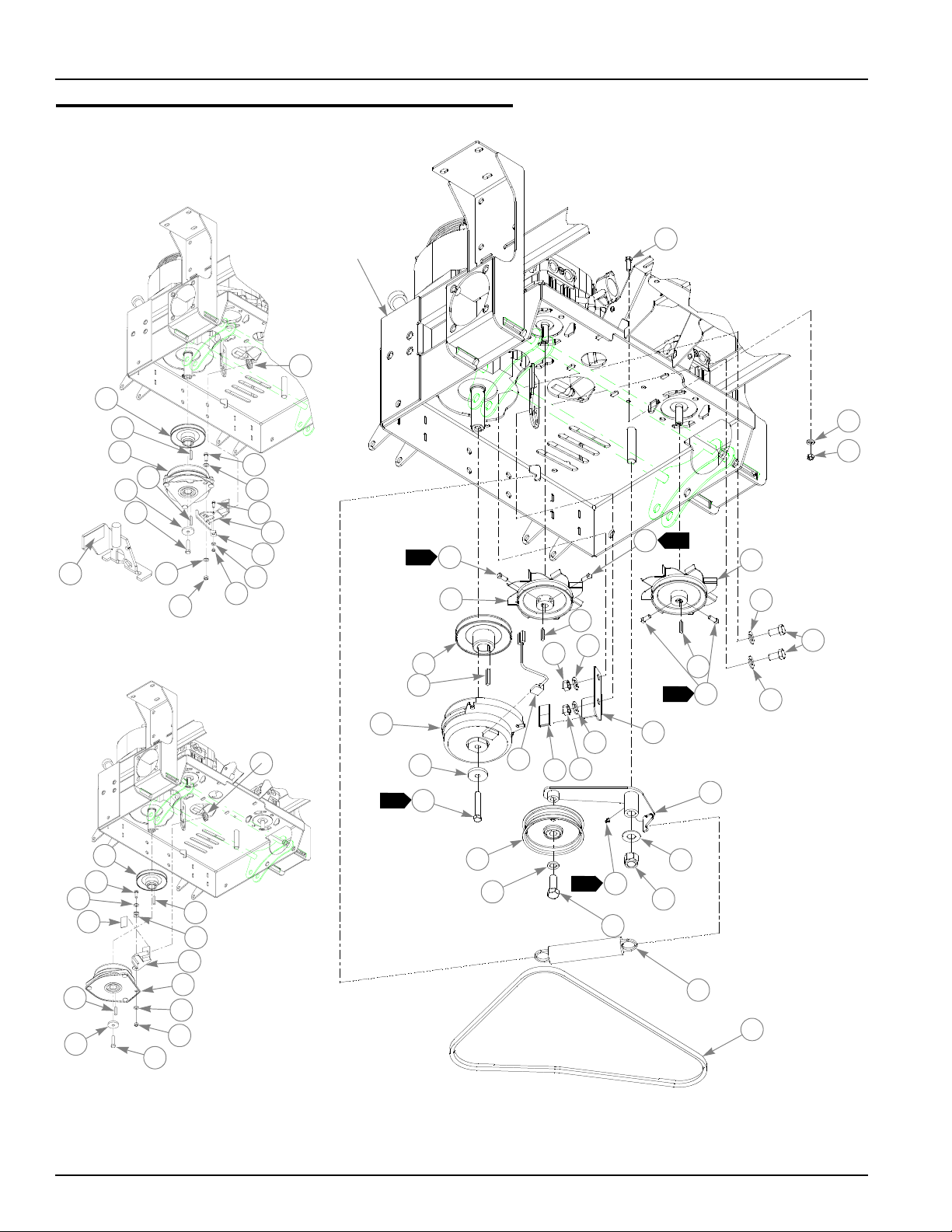
72" Deck Pulley Assembly
10
4
APPROXIMATE
LOCATION
OF BUMPERS
16
11
15
1
2
4
7
3
9
8
3
5
6
12
13
3
14
18
BELT GUIDE
POSITIONING
18
18
29
17
2
3
28
4
19
28
20
2
21
22
23
21
24
27
18
25
26
1
30
7-4 375535 6/06
Page 69

72" Deck Pulley Assembly
8 5
ITEM
NO.
1 784207 784207 1 B-SECTION BELT
2 016972 016972 2 NT .625-11 HX G5 ZNYC
3 028118 028118 3 FW .62 X 1.00X.134 ZN
4 781385 781385 2 6.00" IDLER PULLEY,
5 008573 008573 1 CS .500-13 X 2.500 HX G5 ZN
6 070037 070037 1 FW .530 X 1.06 X .19 HRD ZN
7 350561 350561 1 DECK IDLER BUSHING
8 015495 015495 1 STRAIGHT GREASE FITTING
9 349498 349498 1 IDLER ARM
10 781302 781302 1 IDLER SPRING
11 373191 059931 1 SIDE MOUNT CHAIN
12 794446 794446 1 CS .625-11 X 1.50 HX G5 ZN
13 347443 347443 1 TOP IDLER DECK BELT GUIDE
14 781856 781856 1 5.00" IDLER PULLEY
15 781617 781617 2 RUBBER BUMPER
16 348375 348375 1 R.S. PULLEY COVER
17 348524 348524 1 L.S. PULLEY COVER
18 792002 792002 4 5/16-18 X 3/4"MALE KNOB
7
19 784199 784199 3 CS .312-18 X 1.250 FLT SH ZNYC
20 783878 783878 1 IDLER CLAMP
21 016527 016527 15 CS .500-13 X 1.00 HX G5 ZN
22 078386 078386 3 FW .510 X 1.750 X .18 ZN
23 538850 538850 3 DRIVE PULLEY
24 767962 767962 12 FW .531 X 1.063 X .090 SAE HD ZN
25 796235 796235 3 SPINDLE HOUSING ASSEMBLY
6
25 350595K 350595 3 SPINDLE HOUSING ASSEMBLY
26 212472 212472 3 KEY 1/4 SQ X 1.00 LONG
27 795260 795260 3 BLADE,F23.86"-H-F-CW
8
8
28 782474 782474 5 CW .631 2.250 X .187 PNT
29 783738 783738 2 CS .625-11 X 3.00 FULL HX G5 ZN
30 029934 029934 3 CS .625-11 X 3.00 HX G5 ZNYC
SERVICE
PAR T NO.
075291 N/A 4 CLAMP KNOB
783977 N/A 3 24" OFFSET FLAT BLADE
794867 N/A 3 OPTIONAL BLADE, 23.86"-GAT-F-CW
784728 N/A 3 OPTIONAL 24" GATOR BLADE CW
MFG.
PART NO.
QTY DESCRIPTION
NOTES:
1. Torque to 118 ft. lbs.
2. Torque to 67-75 ft. lbs.
3. Apply grease to zerk (see owner’s manual).
4. See ’’Deck Belt Routing and Tensioning” in Chapter 8 on page 8-4 for
belt tensioning.
5. See ’’Spindle Assembly - 350595K” in Chapter 7 on page 7-19 for
breakdown.
6. See ’’Spindle Assembly - 796235” in Chapter 7 on page 7-20 for
breakdown.
375535 6/06 7-5
Page 70

7. Used on mowers with serial number prior to 04032000.
8. Used on mowers with serial number pior to 05011098.
7-6 375535 6/06
Page 71

This page intentionally left blank.
375535 6/06 7-7
Page 72

60" Deck Assembly
3
2
1
4
5
4
16
9
8
12
15
12
11
13
9
17
5
4
6
7
14
8
1
10
17
4
14
8
12
15
12
11
11
13
12
8
13
15
5
9
4
11
12
15
13
12
9
7-8 375535 6/06
Page 73

60" Deck Assembly
INDEX NO.
1 545277 349100 1 60" DECK CRATED
3
2 349324 349324 1 DISCHARGE CHUTE
3 052860 052860 2 CS .375-16 X 1.250 HX G5 ZN
4 767954 767954 18 FW .406 X .812 X .060 SAE HD ZN
5 054502 054502 8 NT .375-16 HX GRD 5 ZN
6 349522 349522 1 DISCHARGE CHUTE MOUNT BRACKET
7 086660 086660 2 NT .375-16 HX LK NY
8 808485 808485 4 5/16-18 THREAD RIVET NUT
9 781708 N/A 4 CS .500-13 X 4.25 HX G5 ZN
10 349803 349803 1 PUSHER
11 053199 N/A 4 NT .500-13 HX JAM ZN
12 767962 N/A 8 FW .531 X 1.063 X .090 SAE HD ZN
13 781567 781567 4 NT .50-13 HX LK NY
14 015495 015495 2 STRAIGHT GREASE FITTING
15 031997 N/A 4 ANTI-SCALP WHEEL
16 781880 781880 1 BUMPER
17 036244 036244 8 CS .375-16X1.000 HX G5 ZN
2
SERVICE
PAR T NO.
788166 788166 4 ANTI SCALP WHEEL ASSY
MFG.
PART NO.
QTY. DESCRIPTION
NOTES:
1. Do not torque, Item 2 (349324 Discharge Chute) must pivot freely.
2. Includes items 9, 11, 12, and 15.
3. Service part deck includes decals (see ’’72" and 60" Deck Decals” in
Chapter 9 on page 9-4 for listing of decals) and item 2 (Discharge
Chute).
375535 6/06 7-9
Page 74

60" Deck Pulley Assembly
2
1
19
7
10
11
3
4
5
14
2
2
5
8
9
26
20
27
26
21
19
18
19
13
5
6
3
12
6
28
17
4
16
15
60" DECK
BELT GUIDE
POSITIONING
19
29
22
25
25
1
30
7-10 375535 6/06
23
24
APPROXIMATE
LOCATION
OF BUMPERS
Page 75

60" Deck Pulley Assembly
INDEX
NO.
1 781310 781310 1 B-SECTION BELT
2 016972 016972 2 NT .625-11 HX G5 ZNYC
3 794446 794446 1 CS .625-11 X 1.50 HX G5 ZN
4 347443 347443 1 TOP IDLER DECK BELT GUIDE
5 028118 028118 3 FW .62 X 1.00X.134 ZN
6 781385 781385 2 6.00" IDLER PULLEY,
7 008573 008573 1 CS .500-13 X 2.500 HX G5 ZN
8 784199 784199 3 CS .312-18X1.250 FLT SH ZNYC
9 783878 783878 1 IDLER CLAMP
10 070037 070037 1 FW .530 X 1.06 X .19 HRD ZN
11 350561 350561 1 DECK IDLER BUSHING
12 015495 015495 1 STRAIGHT GREASE FITTING
13 349498 349498 1 IDLER ARM
14 781856 781856 1 5.00" IDLER PULLEY
15 781302 781302 1 IDLER SPRING
16 373191 059931 1 SIDE MOUNT CHAIN
17 349381 349381 1 R.S. PULLEY COVER
18 349399 349399 1 L.S. PULLEY COVER
19 792002 792002 4 5/16-18 X 3/4"MALE KNOB
7
20 078386 078386 3 FW .510 X 1.750 X .18 ZN
21 781328 781328 3 B-SECTION 6.10 E.O.D PULLEY
22 350595 350595 3 SPINDLE HOUSING ASSEMBLY
85
22 796235 796235 3 SPINDLE HOUSING ASSEMBLY
5
23 212472 212472 3 KEY 1/4 SQ X 1.00 LONG
24 782516 N/A 3 21"X 42D X0.631 CW BLADE
8
24 795252 795252 3 BLADE,F20.95"-H-F-CW
8
25 782474 782474 5 CW .631 2.250 X .187 PNT
26 016527 016527 15 CS .500-13 X 1.00 HX G5 ZN
27 767962 767962 12 FW .531 X 1.063 X .090 SAE HD ZN
28 781617 781617 2 RUBBER BUMPER
SERVICE
PAR T NO.
075291 N/A 4 CLAMP KNOB
782557 N/A 3 BLADE,20.95"-GAT-O-CW
794859 N/A 3 BLADE, 20.95"-GAT-F-CW
783738 783738 2 CS .625-11 X 3.00 FULL HX G5 ZN
029934 029934 3 CS .625-11 X 3.00 HX G5 ZNYC
MFG.
PART NO.
QTY. DESCRIPTION
NOTES:
1. Torque to 118 ft. lbs.
2. Torque to 65-75 ft. lbs.
3. Apply grease to zerk (see owner’s manual).
4. See ’’Deck Belt Routing and Tensioning” in Chapter 8 on page 8-4 for
belt tensioning.
5. See ’’Spindle Assembly - 350595K” in Chapter 7 on page 7-19 for
breakdown.
6. See ’’Spindle Assembly - 796235” in Chapter 7 on page 7-20 for
breakdown.
375535 6/06 7-11
Page 76

7. Used on mowers with serial number prior to 04032000.
8. Used on mowers with serial number prior to 05011098.
7-12 375535 6/06
Page 77

This page intentionally left blank.
375535 6/06 7-13
Page 78

52" Deck Assembly
2
4
1
3
5
4
10
9
17
9
11
10
13
11
11
12
13
4
6
8
1
8
16
8
12
13
10
12
12
13
10
11
15
14
16
4
8
5
9
7-14 375535 6/06
4
9
Page 79

52" Deck Assembly
INDEX NO.
1 545343 347195 1 52" DECK CRATED
3
2 347971 347971 1 52" DISCHARGE CHUTE
3 052860 052860 2 CS .375-16 X 1.25 HX G5 ZN
4 767954 767954 18 FW .406 X .812 X .060 SAE HD ZN
5 054502 054502 8 NT .375-16 HX GRD 5 ZN
6 086660 086660 2 NT .375-16 HX LK NY
7 317073 317073 1 DISCHARGE CHUTE MOUNT BRACKET
8 N/A 808485 4 5/16-18 THREAD RIVET NUT
9 781708 N/A 4 CS .500-13 X 4.25 HX G5 ZN
10 767962 N/A 8 FW .531 X 1.063 X.090 SAE HD ZN
11 053199 N/A 4 NT .500-13 HX JAM ZN
12 781567 781567 4 NT .50-13 HX LK NY
13 031997 N/A 4 ANTI-SCALP WHEEL
14 015495 015495 2 STRAIGHT GREASE FITTING
15 349803 349803 1 PUSHER
16 036244 036244 8 CS .375-16 X1.00 HX G5 ZN
17 781880 781880 1 BUMPER
2
SERVICE
PAR T NO.
788166 788166 4 ANTI-SCALP WHEEL ASSEMBLY
MFG.
PART NO.
QTY. DESCRIPTION
NOTES:
1. Do not torque, Item 2 (347971 Discharge Chute) must pivot freely.
2. Includes items 9, 10, 11, and 13.
3. .Service part deck includes decals (see ’’52" Deck Decals” in Chapter 9
on page 9-5 for listing of decals) and item 2 (Discharge Chute).
375535 6/06 7-15
Page 80

52" Deck Pulley Assembly
2
4
5
1
16
52" DECK
4
12
15
16
13
5
6
3
14
2
7
8
28
3
9
4
10
11
2
17
4
29
18
17
20
19
21
16
BELT GUIDE
POSITIONING
4
26
25
27
7-16 375535 6/06
16
1
30
22
23
24
25
Page 81

52" Deck Pulley Assembly
INDEX
NO.
1 782292 782292 1 B-SECTION BELT
2 016972 016972 2 NT .625-11 HX G5 ZNYC
3 794446 794446 1 CS .625-11 X 1.50 HX G5 ZN
4 028118 028118 6 FW .62 X 1.00 X .134 ZN
5 781385 781385 2 6.00" IDLER PULLEY
6 008573 008573 1 CS .500-13 X 2.50 HX G5 ZN
7 070037 070037 1 FW .530 X 1.06 X .19 HRD ZN
8 350561 350561 1 DECK IDLER BUSHING
9 347443 347443 1 DECK BELT IDLER TOP GUIDE
10 781856 781856 1 5.00" IDLER PULLEY
11 349498 349498 1 DECK IDLER ARM
12 373191 059931 1 SIDE MOUNT CHAIN
13 781302 781302 1 IDLER SPRING
14 015495 015495 1 STRAIGHT GREASE FITTING
15 347898 347898 1 RS 52" DECK PULLEY COVER
16 792002 792002 4 5/16-18 X 3/4"MALE KNOB
7
17 016527 016527 15 CS .500-13 X 1.00 HX G5 ZN
18 078386 078386 3 FW .510 X 1.75 X .18 ZN
19 768168 768168 3 DECK DRIVE PULLEY
20 767962 767962 12 FW .531 X 1.063 X .090 SAE HD ZN
21 347914 347914 1 LS 52" DECK PULLEY COVER
22 212472 212472 3 KEY 1/4 SQ X 1.00 LONG
23 796235 796235 3 DECK SPINDLE ASSY
6
8
5
24 795526 795526 3 BLADE, F17.86"-H-F-CW
8
9
89
25 782474 782474 4 CW .631 X 2.250 X .187 PNT
26 783787 783787 1 CS .625-11 X 3.00 SH 2.50"MIN TH
27 783738 783738 1 CS .625-11X3.00 FULL HX G5 ZN
28 784199 784199 3 CS .312-1 8X 1.250 FLT SH ZNYC
29 783878 783878 1 IDLER CLAMP
30 029934 029934 3 CS .625-11 X 3.00 HX G5 ZNYC
SERVICE
PAR T NO.
075291 N/A 4 CLAMP KNOB
350595 350595 3 DECK SPINDLE ASSY
781898 N/A 3 BLADE, 17.86"-M-O-CW
783753 N/A 3 OPTIONAL BLADE,17.86"-L-F-CW
785436 N/A 3 OPTIOAL BLADE, 17.86"-GAT-F-CW
782532 N/A 3 OPTIONAL BLADE, 17.86"-GAT-O-CW
MFG.
PART NO.
QTY. DESCRIPTION
NOTES:
1. Torque to 118 ft. lbs.
2. Torque to 65-75 ft. lbs.
3. Apply grease to zerk (see owner’s manual).
4. See ’’Deck Belt Routing and Tensioning” in Chapter 8 on page 8-4 for
belt tensioning.
5. See ’’Spindle Assembly - 350595K” in Chapter 7 on page 7-19 for
breakdown.
6. See ’’Spindle Assembly - 796235” in Chapter 7 on page 7-20 for
375535 6/06 7-17
Page 82

breakdown.
7. Used on mowers with serial number prior to 04032000.
8. Used on mowers with serial number prior to 05011098.
9. Used with mulch kit only.
7-18 375535 6/06
Page 83

Spindle Assembly - 350595K
4
5
1
1
2
3
2
1
6
INDEX
NO.
1 077123 N/A 2 BEARING W/O COLLAR
2 766204 N/A 1 BLADE SPINDLE BUSHING
3 034843 N/A 1 CAST SPINDLE HOUSING
4 012005 N/A 1 GREASE FITTING
5 072272 N/A 1 FW 1.06 X 2.00 X.134 SAE ZN
6 788547 N/A 1 SADDLELESS SPINDLE SHAFT
SERVICE
PAR T NO.
MFG.
PART NO.
QTY. DESCRIPTION
NOTES:
1. Install upper bearing with extended inner race up.
2. Install lower bearing with extended inner race down.
3. Used on mowers with serial number prior to ?
375535 6/06 7-19
Page 84

Spindle Assembly - 796235
4
5
1
1
2
3
2
1
6
INDEX
NO.
1 077123 N/A 2 BEARING W/O COLLAR
2 766204 N/A 1 BLADE SPINDLE BUSHING
3 034843 N/A 1 CAST SPINDLE HOUSING
4 012005 N/A 1 GREASE FITTING
5 072272 N/A 1 FW 1.06 X 2.00 X.134 SAE ZN
6 796227 N/A 1 SADDLELESS SPINDLE SHAFT
SERVICE
PAR T NO.
MFG.
PAR T NO.
QTY. DESCRIPTION
NOTES:
1. Install upper bearing with extended inner race up.
2. Install lower bearing with extended inner race down.
7-20 375535 6/06
Page 85

Chapter 8 Contents
Deck Installation . . . . . . . . . . . . . . . . . . . . . . . . . . . . . . . . . . . . . . . . 8-2
Deck Belt Routing and Tensioning. . . . . . . . . . . . . . . . . . . . . . . . . . . 8-4
Seat Installation . . . . . . . . . . . . . . . . . . . . . . . . . . . . . . . . . . . . . . . . . 8-6
375535 6/06 8-1
Page 86

Deck Installation
TRACTOR
ASSEMBLY
1
1
4
3
2
5
DECK
ASSEMBLY
5
8-2 375535 6/06
Page 87

Deck Installation
ITEM
NO.
1 055749 055749 4 CS .437-14 X 1.750 HX G5 ZN
2 061101 061101 2 NT .750-10 HX NL ZN
3 025296 025296 4 FW .760 X 1.625 X.08 ZN
4 051169 051169 2 CS .750-10 X 3.000 HX G5 ZN
5 704643 704643 8 NT .437-14 HX FLG ZN
SERVICE
PART NO.
MFG.
PART NO.
QTY DESCRIPTION
NOTES:
1. 60" Deck installation is shown, 52" and 72" Deck installations are similar.
375535 6/06 8-3
Page 88

Deck Belt Routing and Tensioning
1
DECK
ASSEMBLY
8-4 375535 6/06
Page 89

NOTES:
1. Spring length after tensioning belt. Measure spring from outside of hook
to outside of hook.
2. Route belt as shown.
375535 6/06 8-5
Page 90

Seat Installation
15
8
5
14
3
4
5
17
16
1
4
3
1
2
1
8
9
6
7
10
13
4
5
5
11
12
12
8-6 375535 6/06
Page 91

Seat Installation
INDEX
NO.
1 793661 793661 1 MICHIGAN STANDARD SEAT
2
3
2 350041 350041 1 SEAT PAN
3 000331 000331 3 BLACK CABLE TIE
4
4 086660 086660 3 NT .375-16 HX LK NY
5 767954 767954 7 FW .406 X .812 X .060 SAE HD ZN
6 724716 724716 1 FIBER WASHER
7 350421 350421 1 SEAT PAN STOP
8 036244 036244 3 CS .375-16 X 1.000 HX G5 ZN
9 052860 052860 2 CS .375-16 X1.250 HX G5 ZN
10 768523 768523 4 FW .343 X .687 X .051/.080 HD ZN/Y
11 034272 034272 4 NT .312-18 HX G5 ZN
12 781880 781880 2 BUMPER
13 080358 080358 1 GM .50 X 1.00 X .75 X .12 GROMMET
14 748756 748756 1 LATCH SPRING PLUNGER
15 350462 350462 1 SEAT LATCH BRACKET
16 781617 781617 3 RUBBER BUMPER
17 722199 722199 1 2" WIDE SCOTCH POLYURETHANE 5.55" LONG
SERVICES
PART NO.
792051 792051 1 MICHIGAN SUSPENSION SEAT
MFG.
PART NO.
QTY DESCRIPTION
NOTES:
1. Must pivot freely.
2. Used on 926667, 926881, 926915, and 926931 only.
3. Used on 926675, 926923, 926949, 926964, 927111, and 927160 only.
4. Use quantity of 3 for 926667, 926881, 926915, and 926931 and quantity
of 2 for 926675, 926923, 926949, 926964, 927111, and 927160 (do not
use rear strap for 926675, 926923, 926949, 926694, 927111, and
927160).
5. Service parts available for Michigan Standard seat;
PART NO.
793695 SLIDE KIT
797464 L.H. ARMREST ASSMBLY
797472 R.H. ARMREST ASSMBLY
793315 SEAT SWITCH
797480 MOLDED ARMREST KIT (INCLUDES BOTH ARMRESTS)
793273 ARMREST STOP ASSY
DESCRIPTION
6. Service parts available for Michigan Suspension seats:
PART NO.
793307 SLIDE KIT
793323 KNOB KIT
793281 BACK CUSHION KI
793299 SEAT CUSHION KIT
793315 SEAT SWITCH
797480 MOLDED ARMREST (FITS BOTH SIDES)
DESCRIPTION
375535 6/06 8-7
Page 92

PART NO.
793273 ARMREST STOP ASSEMBLY
797571 SEAT BACK PANEL KIT
7. Service parts available for Milsco seats:
DESCRIPTION
PART NO.
782144 ADJUSTER, STANDARD AND LOW PROFILE SUSPENSION SEAT
782151 ARMREST FOR STANDARD SEAT
782169 ARMREST FOR LOW PROFILE SUSPENSION SEAT
782177 OPERATOR PRESENCE SWITCH FOR BOTH SEATS
782185 CUSHION/PAN FOR LOW PROFILE SUSPENSION SEAT
783472 Z ARMREST ONLY KIT
DESCRIPTION
8-8 375535 6/06
Page 93

Chapter 9 Contents
Tractor Decals . . . . . . . . . . . . . . . . . . . . . . . . . . . . . . . . . . . . . . . . . . 9-2
72" and 60" Deck Decals . . . . . . . . . . . . . . . . . . . . . . . . . . . . . . . . . . 9-4
52" Deck Decals . . . . . . . . . . . . . . . . . . . . . . . . . . . . . . . . . . . . . . . . 9-5
375535 6/06 9-1
Page 94

Tractor Decals
A
4
2
8
1
17
6
A
3
5
9
TOP OF
SEAT PAN
10
BOTTOM OF
SEAT PAN
11
12
7
9-2 375535 6/06
13
14
15
Page 95

Tractor Decals
16
INDEX
NO.
1 781427 781427 1 DECK HEIGHT INDICATOR DECAL
2 779280 779280 1 HOT & HYDRAULIC OIL DECAL
3 784702 784702 1 INSTRUMENT PANEL DECAL (SEPARATE CHOKE)
4 727008 727008 1 HYD PRESSURE DECAL
5 791830 791830 1 FUEL INDICATOR DECAL
6 782136 782136 1 Z OPERATION DECAL
7 788968 788968 1 ENGINE COMPARTMENT DECAL
8 785188 785188 1 Z ARMREST WARNING DECAL
9 782128 782128 1 Z SERVICE DECAL
10 727016 727016 1 BATTERY DECAL
11 771436 771436 1 STABILIZER DECAL
12 727172 727172 1 MADE IN USA DECAL
13 N/A 083279 1 TURF PROD SERIAL NO PLATE
14 782573 782573 1 FIRST ZERO TURN DECAL
15 793588 793588 1 HUSTLER NAME PLATE
16 786426 786426 1 HUSTLER Z ID DECAL
17 600899 600899 1 PUMP BELT WARNING DECAL
SERVICE
PAR T NO.
MFG.
PAR T NO.
QTY. DESCRIPTION
NOTES:
375535 6/06 9-3
Page 96

72" and 60" Deck Decals
1
8
3
4
2
7
6
4
5
3
INDEX
NO.
1 786277 786277 1 60" SIDE DISCHARGE DECK ID DECAL
2 781419 781419 1 BELT ROUTING DECAL
3 727438 727438 2 WHIRLING BLADES DECAL
4 727453 727453 2 BELT & PULLEY DECAL
5 727420 727420 1 DEFLECTOR SHIELD DECAL
6 727172 727172 1 "MADE IN U.S.A." DECAL
7 760637 760637 1 MOWER DECK QUICK REFERENCE DECAL
8 797845 797845 1 FUSION DECAL
SERVICE
PAR T NO.
786285 786285 1 72" SIDE DISCHARGE DECK ID DECAL
MFG.
PAR T NO.
QTY. DESCRIPTION
NOTES:
9-4 375535 6/06
Page 97

52" Deck Decals
1
2
7
6
8
4
5
3
4
3
INDEX
NO.
1 785535 785535 1 52" SIDE DISCHARGE DECK ID DECAL
2 781419 781419 1 BELT ROUTING DECAL
3 727438 727438 2 WHIRLING BLADES DECAL
4 727453 727453 2 BELT & PULLEY DECAL
5 727420 727420 1 DEFLECTOR SHIELD DECAL
6 727172 727172 1 "MADE IN U.S.A." DECAL
7 760637 760637 1 MOWER DECK QUICK REFERENCE DECAL
8 797845 797845 1 FUSION DECAL
SERVICE
PAR T NO.
MFG.
PART NO.
QTY. DESCRIPTION
NOTES:
375535 6/06 9-5
Page 98

9-6 375535 6/06
Page 99

Chapter 10 Contents
72" and 60" Mulch Kits. . . . . . . . . . . . . . . . . . . . . . . . . . . . . . . . . . . 10-2
72" Mulch Kit–352419 . . . . . . . . . . . . . . . . . . . . . . . . . . . . . . . . . . . 10-3
60" Mulch Kit–352427 . . . . . . . . . . . . . . . . . . . . . . . . . . . . . . . . . . . 10-4
52" Mulch Kit - 344929 . . . . . . . . . . . . . . . . . . . . . . . . . . . . . . . . . . 10-5
52" Mulch Kit–352435 . . . . . . . . . . . . . . . . . . . . . . . . . . . . . . . . . . . 10-6
375535 6/06 10-1
Page 100

72" and 60" Mulch Kits
3
1
2
2
1
2
3
4
1
2
5
6
1
2
INDEX
NO.
SERVICE
PART NO.
1 054502 054502 7 NT .375-16 HX GRD 5 ZN
2 767954 767954 9 FW .406 X .812 X.060 SAE HD ZN
3 036244 036244 2 CS .375-16 X 1.00 HX G5 ZN
4 011320 011320 1 CB .375-16 X .750 STD ZN
5 346056 346056 1 RIGHT MULCH BAFFLE
6 346023 346023 2 60" COMMON MULCH BAFFLE
348599 348599 2 72” COMMON MULCH BAFFLE
MFG. PART
NO.
QTY. DESCRIPTION
NOTES:
1. 60" Mulch Kit - 346411
2. 72" Mulch Kit - 357608
3. Used on mowers with serial number prior to 05011098.
6
10-2 375535 6/06
 Loading...