

Page 1

Hustler Z Bac Vac
Parts Manual
353326 Rev. 6/06
•••••••
Hustler Turf Equipment
•••••
P.O. Box 7000
•••
Hesston, Kansas
•
67062-2097
Page 2

Page 3

Table of Contents
Chapter 1
General Information . . . . . . . . . . . . . . . . . . . . . . . . . . . . . . . . . . . . 1-1
Chapter 2 Contents
Hopper Front Assembly . . . . . . . . . . . . . . . . . . . . . . . . . . . . . . . . . 2-2
Door Assembly . . . . . . . . . . . . . . . . . . . . . . . . . . . . . . . . . . . . . . . . 2-4
Hopper Assembly 353219. . . . . . . . . . . . . . . . . . . . . . . . . . . . . . . . 2-6
Chapter 3 Contents
Blower Assembly 544510 . . . . . . . . . . . . . . . . . . . . . . . . . . . . . . . . 3-2
Transition Chute Assembly 544510 . . . . . . . . . . . . . . . . . . . . . . . . 3-4
Spindle Housing Assembly 520627 . . . . . . . . . . . . . . . . . . . . . . . . 3-6
Chapter 4 Contents
Blower Installation, 72" Deck . . . . . . . . . . . . . . . . . . . . . . . . . . . . . 4-2
Blower Installation, 60" Deck . . . . . . . . . . . . . . . . . . . . . . . . . . . . . 4-4
Blower Installation, 52" Deck . . . . . . . . . . . . . . . . . . . . . . . . . . . . . 4-6
Blower Installation, 72" XR7 Deck . . . . . . . . . . . . . . . . . . . . . . . . . 4-8
Blower Installation, 66" XR7 Deck . . . . . . . . . . . . . . . . . . . . . . . . . 4-10
Blower Installation, 60" XR7 Deck . . . . . . . . . . . . . . . . . . . . . . . . . 4-12
Blower Installation, 54" XR7 Deck . . . . . . . . . . . . . . . . . . . . . . . . . 4-14
Bac-Vac Installation . . . . . . . . . . . . . . . . . . . . . . . . . . . . . . . . . . . . 4-16
Weight Installation. . . . . . . . . . . . . . . . . . . . . . . . . . . . . . . . . . . . . . 4-18
Index . . . . . . . . . . . . . . . . . . . . . . . . . . . . . . . . . . . . . . . . . . . . . . . . . . . . . . . . i-1
353326 6/06
Page 4

353326 6/06
Page 5

Chapter 1
General Information
This Manual covers 353177K Hustler Z Bac Vac for 52" Deck, 353185K Hustler Z Bac Vac for 60"
Deck, 357582K Hustler Z Bac Vac for 72" Deck, 926337 Hustler Z Bac Vac Assembly, 928218 Hustler Z XR7 Bac Vac Assembly, 353193 Hustler Z 52” Deck Adapter Kit, 353201 Hustler Z 60" Deck
Adapter Kit, and 325084 Hustler Z 72" Deck Adapter Kit, 107110 54" XR7 Adapter Kit, 107128 60"
XR7 Adapter Kit, 107136 66" XR7 Adapter Kit, and 107144 72" XR7 Adapter Kit.
Service Literature
PART NO. DESCRIPTION
353318 Hustler Z Bac Vac Owner’s Manual
107086 XR7 Bac Vac Owner’s Manual
353326 Parts Manual
Note: When ordering parts, yo u must use the part number as shown for each part, not the index number . Always give
the model and serial number to your parts and service represen tative.
Note: Items sold in bulk such as seals and hoses are sold by the foot.
Using this manual
Illustrations used were current at the time of printing, but subsequent production changes may cause your machine to
vary slightly in detail. Excel Industries, Inc. reserves the right to redesign and change the machine as deemed nece ssary, without notification. If a change has been made to your machine which is not reflected in this parts manual, see
your Hustler dealer for current information and parts.
353326 6/06 1-1
Page 6

Hardware Description Codes & Abbreviations
The following codes are used throughout this parts manual. Refer to this list when ordering parts.
ABBREVIATION DESCRIPTION
CB Carriage Bolt
CE Clevis Pin
CP Cotter Pin
CS Cap Screw
CW Cup Washer
FDRW Fender Washer
FW Flat Washer
HX Hex Head
LW Lock Washer
MB Machine Bushing
MS Machine Screw
NT Nut
SC Self Tapping Cap Screw
SH Socket Head
SB Shoulder Bolt
SS Set Screw
OD Outside Diameter
ID Inside Diameter
Standard Torques
The following chart lists the standard torque va lues for the threaded fasteners found in this manual. Torque all cap
screws, nuts and set screws to these values unless a different torq ue is shown in the Notes section n ext to the fastener
SIZE FT-LBS NM SIZE FT-LBS NM
.250 8.2 11.1 M3 1 1.3
.312 17 23 M4 2.2 3
.375 30 40 M5 4.5 6.1
.438 48 65 M6 7.7 10.4
.500 73 99 M8 18.5 25
.562 105 143 M10 37 50
.625 145 200 M12 64 87
.750 260 350 M16 160 215
.875 420 565 M20 320 435
1.00 625 850 M24 555 750
NOTE:
Lubricate all grease zerks.
1-2 353326 6/06
Page 7

Chapter 2 Contents
Hopper Front Assembly . . . . . . . . . . . . . . . . . . . . . . . . . . . . . . . . . . 2-2
Door Assembly . . . . . . . . . . . . . . . . . . . . . . . . . . . . . . . . . . . . . . . . . 2-4
Hopper Assembly 353219 . . . . . . . . . . . . . . . . . . . . . . . . . . . . . . . . . 2-6
353326 6/06 2-1
Page 8
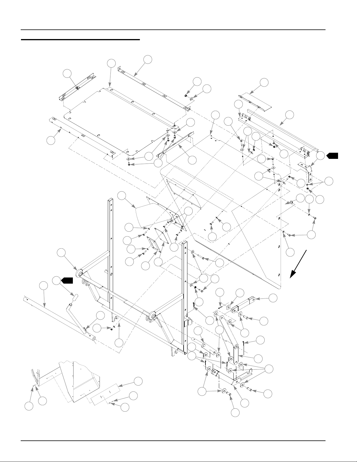
Hopper Front Assembly
22
3
5
6
15
9
7
7
8
18
23
1
13
11
13
20
24
10
16
7
12
7
14
13
18
19
13
8
17
12
2
13
A
13
2
1
4
21
13
18
36
13
18
12
34
13
35
VIEW A
6
26
31
28
27
25
27
28
28
29
32
28
27
30
28
32
33
32
1
37
12
13
38
18
7
28
27
2-2 353326 6/06
Page 9

Hopper Front Assembly
INDEX
NO.
10 301119 301119 1 SPOUT DEFLECTOR
11 008581 008581 1 CS .250-20X1.500 HX G5 ZN
12 068551 068551 13 NT .250-20 HX NL ZN
13 017079 017079 26 FW .250X .560X.04 SAE ZN
14 704163 704163 4 CS .250-20 X 2.00 HX G5 ZN
15 300848 300848 1 HINGE
16 737536 737536 1 SEAL .43 X .75 29" LONG
17 499327 499327 1 LH CORNER SUPPORT
18 056077 056077 16 CS .250-20 X 1.00 HX G5 ZN
19 758789 758789 6 NT .312-18 CAMTAINER FASTNER
20 055939 055939 1 CS .250-20 X .75 HX G5 ZN
21 499426 499426 1 SPOUT
22 301770 301770 1 WINDOW TRIM
23 760512 760512 1 OVERFLOW WINDOW
24 064345 064345 4 CS .312-18 X 2.00 HX G5 ZN
25 036236 036236 6 CS .312-18 X 1.00 HX G5 ZN
26 017004 017004 6 LW .312 MED SPRING ZN
27 011387 011387 10 CP .125D X 1.250 LG HML ZN
28 443549 443549 24 PIVOT BEARING DISC
29 496588 496588 2 DOOR LINKAGE
30 499459 499459 2 DOOR STRAP LINKAGE
31 496554 496554 1 LH PIVOT LINKAGE
32 027714 027714 6 CE .500 X 1.25 .156 X 1.093 ZN
33 496562 496562 1 RH DOOR LATCH LINKAGE
34 347765 347765 1 HANDLE
35 758854 758854 1 UV .75 ID X 5" LG BLACK GRIP
36 496513 496513 1 BAC VAC FRAME
37 758631 758631 2 RP .250 X 1.375 HEAVY SPIRAL
38 374843 374843 1 CLOSE OUT PLATE
SERVICE
PART NO.
1 300871 300871 2 SIDE MOUNTING SCREEN ANGLE
2 300822 300822 1 HOPPER SCREEN
3 300897 300897 1 HOPPER SCREEN STRAP
4 300863 300863 1 REAR MOUNTING SCREEN ANGLE
5 058776 058776 4 NT .312-18 HX NL ZN
6 712927 712927 14 FW .344 X 1.00 X.12 HRD ZN
7 704304 704304 26 FDW 1.00 X .281 X .06 ZN
8 064329 064329 17 CS .25-20 X .625 HX G5 ZN
9 757278 757278 1 FIBERGLASS HOPPER
499319 499319 1 RH CORNER SUPPORT
496547 496547 1 RH PIVOT LINKAGE
496570 496570 1 LH DOOR LATCH LINKAGE
MFG. PART
NO.
QTY. DESCRIPTION
NOTES:
1. Glue with 750265 Scotch™ Grip Plastic Adhesive.
2. Adjust both corner supports to the upper corners and tighten top bolts on
hinge first then side bolts.
353326 6/06 2-3
Page 10
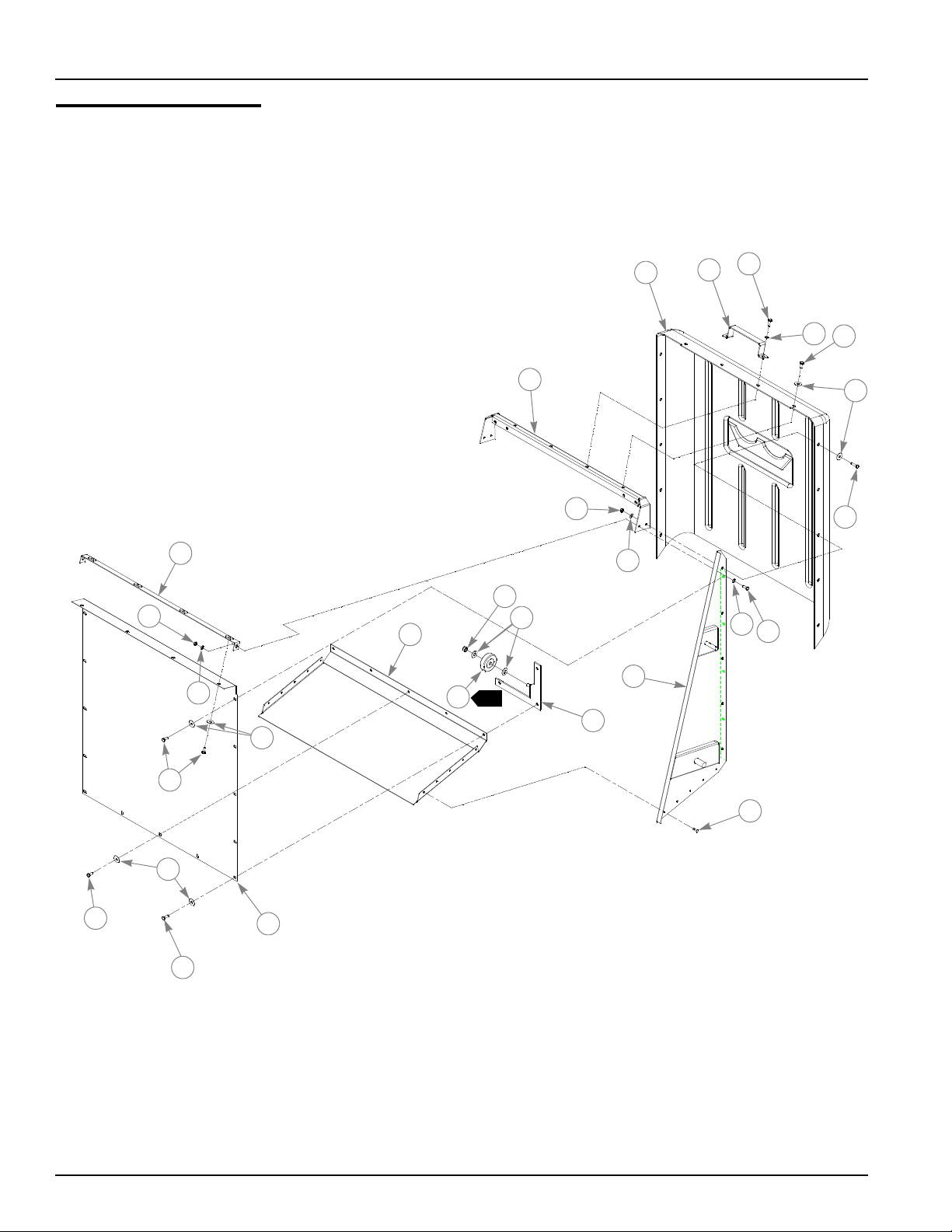
Door Assembly
3
1
2
4
5
10
11
10
17
14
13
16
4
6
5
15
1
12
4
4
3
8
9
6
7
6
5
3
18
2-4 353326 6/06
Page 11

Door Assembly
INDEX
NO.
10 068551 068551 4 NT .250-20 HX NL ZN
11 499400 499400 1 DOOR CHANNEL
12 301036 301036 1 LH WHEEL BRACKET
13 076422 076422 4 FW .406 X 1.000 X .06 ZN
14 086660 086660 2 NT .375-16 HX LK NY
15 760181 760181 2 2.5X.75 3/8 BORE GRAY WHEEL
16 300855 300855 1 BOTTOM PLATE
17 300889 300889 1 DOOR SCREEN STRAP
18 300814 300814 1 DOOR SCREEN
SERVICE
PART NO.
1 496232 496232 1 REAR DOOR COVER
2 301101 301101 1 HANDLE
3 055939 055939 10 CS .250-20 X .750 H X G5 ZN
4 017079 017079 8 FW .250 X .560 X .04 SAE ZN
5 064329 064329 21 CS .250-20 X .625 HX G5 ZN
6 704304 704304 29 FDW 1.000 X .281 X .06 ZN
7 056077 056077 2 CS .250-20 X1.000 HX G5 ZN
8 499301 499301 1 LH DOOR
499293 499293 1 RH DOOR
9 760140 760140 10 RIVET .187 X .375 X .375 HD DIA
301028 301028 1 RH WHEEL BRACKET
MFG. PART
NO.
QTY. DESCRIPTION
1. Wheel to turn freely.
NOTES:
353326 6/06 2-5
Page 12
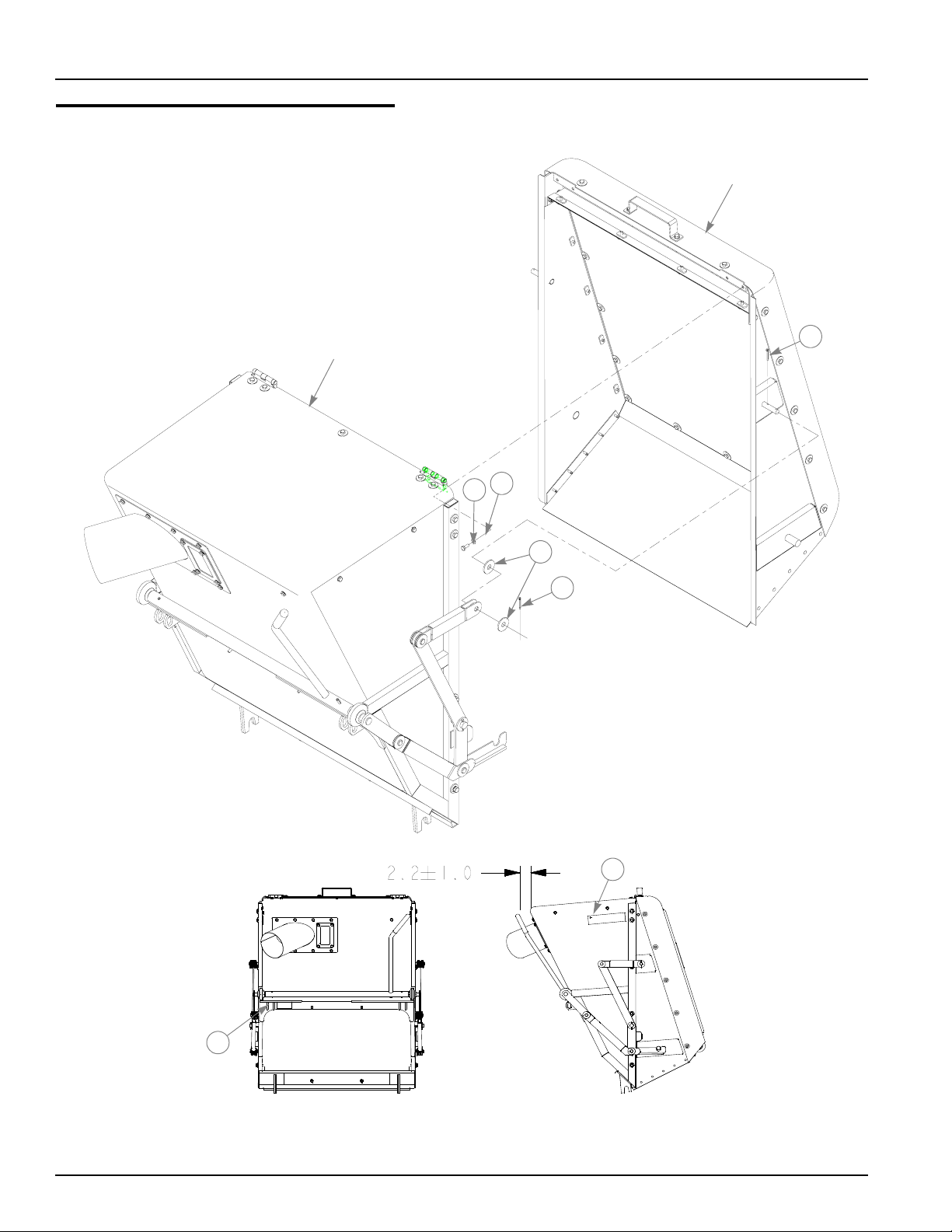
Hopper Assembly 353219
HOPPER DOOR
ASSEMBLY
HOPPER FRONT
ASSEMBLY
4
2
1
3
4
6
5
2-6 353326 6/06
Page 13

Hopper Assembly 353219
INDEX
NO.
SERVICE
PART NO.
1 064329 064329 4 CS .250-20 X .625 HX G5 ZN
2 017079 017079 4 FW .250 X .560 X.04 SAE ZN
3 443549 443549 4 PIVOT BEARING DISC
4 011387 011387 4 CP .125D X 1.250 LG HML ZN
5 741264 741264 1 MADE IN U.S.A.-COMBO DECAL
6 758532 758532 2 BAC VAC ID DECAL
MFG. PART
NO.
QTY. DESCRIPTION
NOTES:
1. Door to be flush with top surface of hopper assembly. Adjust door until
sides align evenly with hopper. If needed, continue to adjust door until
door assembly rests against the hopper in the closed position. Finish
installing linkage.
2. Rotate handle several times to ensure proper opening and closing of
door assembly, adjust as required.
3. Adjust 374843 (Close Out Plate) to close gap between front assembly
and door assembly see ‘Chapter 2, ‘Hopper Front Assembly” on
page 2-2
353326 6/06 2-7
Page 14

2-8 353326 6/06
Page 15

Chapter 3 Contents
Blower Assembly 544510 . . . . . . . . . . . . . . . . . . . . . . . . . . . . . . . . . 3-2
Transition Chute Assembly 544510. . . . . . . . . . . . . . . . . . . . . . . . . . 3-4
Spindle Assembly 520627. . . . . . . . . . . . . . . . . . . . . . . . . . . . . . . . . 3-6
353326 6/06 3-1
Page 16

Blower Assembly 544510
1
1
3
11
12
2
5
2
4
13
14
21
22
2
20
23
25
24
15
17
16
22
18
30
25
3
6
7
3
6
8
10
3
2
1
1
16
19
1
2
3
4
9
11
26
10
2
33
34
35
36
27
2
20
3
11
28
2
1
3-2 353326 6/06
19
17
32
24
22
29
31
23
22
Page 17

Blower Assembly 544510
INDEX
NO.
10 212472 212472 4 KEY
11 045765 045765 5 FW 1.030 X 1.50 X .134 ZN
12 705194 705194 4 CS .50-13 X .750 HX G5 ZN
13 034272 034272 6 NT .312-18 HX G5 ZN
14 768523 768523 6 FW .343 X .687 X .051/.080 HD ZN
15 324319 324319 1 BLOWER HOUSING
16 074252 074252 2 CS .50-13 X 1.50 HX G5 ZN
17 263517 263517 2 BEARING DISK
18 324343 324343 1 UPPER IDLER ARM
19 068759 068759 6 CW .560 X 1.340 X .050 PN
20 023317 023317 2 NT .50-13 UNT LK G5 ZN
21 705178 705178 1 CS .375-16 X 1.750 HX G5 ZN
22 767954 767954 7 FW .406 X .812 X .060 SAE HRD ZN
23 022772 022772 2 FLAT IDLER PULLEY
24 036384 036384 2 SPRING 1/4 COIL PL 1.23
25 259812 259812 2 DECK LIFT SPRING CHAIN
26 520627 426296 1 SPINDLE HOUSING ASSEMBLY
27 016527 016527 4 CS .50-13 X 1.00 HX G5 ZN
28 301317 301317 1 PULLEY
29 324293 324293 1 LOWER IDLER ARM
30 705731 705731 1 CS .375-16 X 2.750 G5 ZN
31 324350 324350 1 IDLER SPACER
32 054502 054502 1 NT .375-16 HX G5 ZN
33 079194 079194 6 MS .25-20 X .750 TH CR ZN
34 324335 324335 1 BLOWER INLET
35 768515 768515 6 FW .281 X .625 X .051/.080 HD ZN
36 024927 024927 6 NT .25-20 HX G5 ZN
SERVICE
PART NO.
1 078378 078378 4 CS .50-20 X 1.50 HX G5 ZN
2 017046 017046 12 LW .50 MEDIUM SPRING ZN
3 078386 078386 4 FW .510 X 1.750 X .180 ZN
4 301267 301267 2 DRIVE PULLEY
5 324327 324327 1 BLOWER TOP
6 077123 077123 2 BEARING W/O COLLAR
7 022582 022582 1 CAST SPINDLE HOUSING
8 758565 758565 1 IMPELLER 11”
9 758730 758730 1 JACK SHAFT
MFG PART
NO.
QTY. DESCRIPTION
NOTES:
1. Torque bottom bolt to 65 ft. lbs. first then torque top bolt to 65 ft. lbs.
2. Tighten to snug up assembly and still allow idler to rotate. Apply Loctite® 242.
3. Assemble bearings in spindle housing with extended race to the inside.
353326 6/06 3-3
Page 18

Transition Chute Assembly 544510
1
2
5
3
4
10
11
6
2
BLOWER
ASSEMBLY
1
9
8
7
3-4 353326 6/06
Page 19

Transition Chute Assembly 544510
INDEX
NO.
10 727453 727453 1 BELT & PULLEY DECAL
11 727438 727438 1 WHIRLING BLADES DECAL
SERVICE
PART NO.
1 064329 064329 4 CS .25-20 X .625 HX G5 ZN
2 768515 768515 10 FW .281 X .627 X .051/.080 HD ZN
3 770180 770180 1 PULLEY COVER
4 770404 770404 1 UPPER BLOWER BELT
5 024927 024927 6 NT .25-20 HX G5 ZN
6 017038 017038 6 LW .25 MEDIUM SPRING ZN
7 757245 757245 1 TRANSITION CHUTE
8 079194 079194 6 MS .25-20 X .750 TH CR ZN
9 767012 767012 1 DANGER BLOWER DECAL
MFG PART
NO.
QTY. DESCRIPTION
NOTES:
1. Decal to be readable from blower outlet (hose) side.
353326 6/06 3-5
Page 20

Spindle Housing Assembly 520627
1
1
2
4
3
1
1
3-6 353326 6/06
Page 21

Spindle Housing Assembly 520627
ITEM
NO.
SERVICE
PART NO.
1 077123 N/A 2 BEARING W/O COLLAR
2 034843 N/A 1 CAST SPINDLE HOUSING
3 008805 N/A 1 SPINDLE SHAFT
4 012005 N/A 1 GREASE FITTING
MFG. PART
NO.
QTY DESCRIPTION
NOTES:
1. Install upper bearing with extended inner race up and lower bearing with
extended inner race down.
353326 6/06 3-7
Page 22

3-8 353326 6/06
Page 23

Chapter 4 Contents
Blower Installation, 72" Deck. . . . . . . . . . . . . . . . . . . . . . . . . . . . . . . 4-2
Blower Installation, 60" Deck. . . . . . . . . . . . . . . . . . . . . . . . . . . . . . . 4-4
Blower Installation, 52" Deck. . . . . . . . . . . . . . . . . . . . . . . . . . . . . . . 4-6
Blower Installation, 72" XR7 Deck. . . . . . . . . . . . . . . . . . . . . . . . . . . 4-8
Blower Installation, 66" XR7 Deck. . . . . . . . . . . . . . . . . . . . . . . . . . 4-10
Blower Installation, 60" XR7 Deck. . . . . . . . . . . . . . . . . . . . . . . . . . 4-12
Blower Installation, 54" XR7 Deck. . . . . . . . . . . . . . . . . . . . . . . . . . 4-14
Bac Vac Installation . . . . . . . . . . . . . . . . . . . . . . . . . . . . . . . . . . . . . 4-16
Weight Installation . . . . . . . . . . . . . . . . . . . . . . . . . . . . . . . . . . . . . . 4-18
353326 6/06 4-1
Page 24

Blower Installation, 72" Deck
2
BLOWER
ASSEMBLY
11
12
11
5
13
1
3
4
1
2
11
14
11
12
8
9
6
EXISTING
HARDWARE
7
EXISTING
HARDWARE
EXISTING
HARDWARE
EXISTING
HARDWARE
10
72" DECK
EXISTING
HARDWARE
11
12
11
12
4-2 353326 6/06
Page 25

Blower Installation, 72" Deck
INDEX
NO.
10 019471 019471 1 CE .380 X 1.75 .150 X 1.60 ZN
11 767954 767954 6 FW .406 X .812 X .060 SAE HD ZN
12 054502 054502 4 NT .375-16 HX GRD 5 ZN
13 325100 325100 1 LOWER BLOWER IDLER COVER
14 101089 101089 1 72" DISCHARGE ADAPTER
3
SERVICE
PART NO.
1 770412 770412 1 LOWER BLOWER BELT
2 036244 036244 2 CS .375-16 X 1.00 HX G5 ZNYC
3 365163 365163 1 PULLEY COVER
4 011320 011320 1 CB .375-16 X .750 STD ZN
5 324301 324301 1 BLOWER PIVOT MOUNT
6 078378 078378 1 CS .500-13 X 1.500 HX G5 ZNYC
7 770388 770388 1 PULLEY
8 023036 023036 1 HP .148 X 2.690 ZN
9 324285 324285 1 BLOWER MOUNT
MFG. PART
NO.
QTY. DESCRIPTION
NOTES:
1. Torque to 65-75 ft. lbs.
2. All components are contained in 325084 Deck Adapter Kit for Hustler Z
Bac Vac except 365163 (Pulley Cover) which is contained in 357582K.
3. Used on mowers with serial numbers after 05011098.
353326 6/06 4-3
Page 26

Blower Installation, 60" Deck
BLOWER
ASSEMBLY
1
2
3
4
1
5
12
7
EXISTING
HARDWARE
8
EXISTING
HARDWARE
EXISTING
HARDWARE
10
11
EXISTING
HARDWARE
6
9
EXISTING
HARDWARE
60" DECK
12
13
12
13
4-4 353326 6/06
12
13
Page 27

Blower Installation, 60" Deck
INDEX
NO.
4
4
3
10 324285 324285 1 BLOWER MOUNT
11 019471 019471 1 CE .380 X 1.75 .150 X 1.60 ZN
12 767954 767954 2 FW .406 X .812 X .060 SAE HD ZN
13 054502 054502 2 NT .375-16 HX GRD 5 ZN
SERVICE
PART NO.
1 770396 770396 1 LOWER BLOWER BELT
2 347468 347468 1 PULLEY COVER
3 011320 011320 1 CB .375-16 X .750 STD ZN
4 324301 324301 1 BLOWER PIVOT MOUNT
5 036244 036244 2 CS .375-16 X 1.00 HX G5 ZNYC
6 101071 101071 1 60" DISCHARGE ADAPTER
7 078378 078378 1 CS .500-20 X 1.500 HX G5 ZN
7 074252 074252 1 CS .500-13 X 1.500 HX G5 ZNYC
8 524785 524785 1 PULLEY
9 023036 023036 1 HP .148 X 2.690 ZN
MFG. PART
NO.
QTY. DESCRIPTION
NOTES:
1. Torque to 65-75 ft. lbs.
2. All components are contained in 353201 Deck Adapter Kit for Hustler Z
Bac Vac , except 347468 (Pulley Cover) which is contained in 353201.
3. Use on deck with saddless spindle assemblies.
4. Used on mowers with serial numbers after 05011098.
353326 6/06 4-5
Page 28

Blower Installation, 52" Deck
BLOWER
ASSEMBLY
1
3
2
4
EXISTING
HARDWARE
EXISTING
HARDWARE
52" DECK
6
11
10
5
9
1
7
8
EXISTING
HARDWARE
EXISTING
HARDWARE
EXISTING
HARDWARE
4-6 353326 6/06
12
13
13
Page 29

Blower Installation, 52" Deck
INDEX
NO.
3
3
10 353268 353268 1 BLOWER MOUNT
11 019471 019471 1 CE .380 X 1.75 .150 X 1.60 ZN
12 767954 767954 4 FW .406 X .812 X .060 SAE HD ZN
13 054502 054502 2 NT .375-16 HX GRD 5 ZN
SERVICE
PART NO.
1 782565 782565 1 LOWER BLOWER BELT
2 353367 353367 1 PULLEY COVER
3 011320 011320 1 CB .375-16 X .750 STD ZN
4 353011 353011 1 BLOWER PIVOT BRACKET
5 025395 025395 2 CB .375-16 X 1.00 STD CD
6 352336 352336 1 52" DISCHARGE ADAPTER
7 074252 074252 1 CS .500-13 X 1.500 HX G5 ZNYC
8 524785 524785 1 PULLEY
9 023036 023036 1 HP .148 X 2.690 ZN
MFG. PART
NO.
QTY. DESCRIPTION
NOTES;
1. Torque to 65 - 75 ft. lbs.
2. All components are contained in 353193 Deck Adapter Kit for Hustler Z
Bac Vac , except 353367 (Pulley Cover) which is contained in 353193.
3. Used on mowers with serial numbers after 05011098.
353326 6/06 4-7
Page 30

Blower Installation, 72" XR7 Deck
2
BLOWER
ASSEMBLY
3
1
3
4
EXISTING
HARDWARE
EXISTING
HARDWARE
8
72" DECK
7
10
5
4
1
6
EXISTING
HARDWARE
9
EXISTING
HARDWARE
11
4-8 353326 6/06
Page 31

Blower Installation, 72" XR7 Deck
INDEX
NO.
10 103036 103036 1 CHUTE MOUNT
11 025395 025395 2 CB .375-16 X 1.00 STD CD
SERVICE
PART NO.
1 787986 787986 1 LOWER BLOWER BELT
2 107622 107622 1 PULLEY COVER
3 086660 086660 2 NT .375-16 HXZY NL
4 767954 767954 2 FW .406 X .812 X .060 SAE
5 102913 102913 1 BLOWER PIVOT MOUNT
6 016527 016527 1 CS .500-13 X 1.00 HX G5 Z
7 023036 023036 1 HP .148 X 2.690 ZN
8 019471 019471 1 CE .380 X 1.75 .150 X 1.60 ZN
9 770388 770388 1 PULLEY
MFG. PART
NO.
QTY. DESCRIPTION
NOTES:
1. Torque to 65-75 ft. lbs.
2. All components are contained in 107144 Deck Adapter Kit for Hustler Z
XR7 72" Bac Vac .
353326 6/06 4-9
Page 32

Blower Installation, 66" XR7 Deck
2
1
BLOWER
ASSEMBLY
EXISTING
HARDWARE
EXISTING
HARDWARE
66" DECK
3
4
7
8
10
3
4
5
1
6
EXISTING
HARDWARE
9
EXISTING
HARDWARE
EXISTING
HARDWARE
11
4-10 353326 6/06
Page 33

Blower Installation, 66" XR7 Deck
INDEX
NO.
10 103036 103036 1 CHUTE MOUNT
11 025395 025395 2 CB .375-16 X 1.00 STD CD
SERVICE
PART NO.
1 787978 787978 1 LOWER BLOWER BELT
2 107622 107622 1 PULLEY COVER 66" XR7 DECK
3 086660 086660 2 NT .375-16 HXZY NL
4 767954 767954 2 FW .406 X .812 X .060 SAE
5 102913 102913 1 BLOWER PIVOT MOUNT
6 016527 016527 1 CS .500-13 X 1.00 HX G5 Z
7 023036 023036 1 HP .148 X 2.690 ZN
8 019471 019471 1 CE .380 X 1.75 .150 X 1.60 ZN
9 524785 711499 1 PULLEY
MFG. PART
NO.
QTY. DESCRIPTION
NOTES:
1. Torque to 65-75 ft. lbs.
2. All components are contained in 107136 Deck Adapter Kit for Hustler Z
XR7 66" Bac Vac .
353326 6/06 4-11
Page 34

Blower Installation, 60" XR7 Deck
BLOWER
ASSEMBLY
2
EXISTING
HARDWARE
7
1
3
4
4
5
1
6
EXISTING
HARDWARE
9
60" DECK
EXISTING
HARDWARE
8
EXISTING
HARDWARE
10
11
4-12 353326 6/06
Page 35

Blower Installation, 60" XR7 Deck
INDEX
NO.
10 103036 103036 1 CHUTE MOUNT
11 025395 025395 1 CB .375-16 X 1.00 STD CD
SERVICE
PART NO.
1 787978 787978 1 LOWER BLOWER BELT
2 103218 103218 1 PULLEY COVER
3 086660 086660 2 NT .375-16 HXZY NL
4 767954 767954 2 FW .406 X .812 X .060 SAE
5 102913 102913 1 BLOWER PIVOT MOUNT
6 016527 016527 1 CS .500-13 X 1.00 HX G5 Z
7 023036 023036 1 HP .148 X 2.690 ZN
8 019471 019471 1 CE .380 X 1.75 .150 X 1.60 ZN
9 524785 711499 1 PULLEY
MFG. PART
NO.
QTY. DESCRIPTION
NOTES:
1. Torque to 65-75 ft. lbs.
2. All components are contained in 107128 Deck Adapter Kit for Hustler Z
XR7 60" Bac Vac .
353326 6/06 4-13
Page 36

Blower Installation, 54" XR7 Deck
2
1
BLOWER
ASSEMBLY
54" DECK
EXISTING
HARDWARE
8
3
4
7
10
4
5
1
6
EXISTING
HARDWARE
9
EXISTING
HARDWARE
EXISTING
HARDWARE
11
4-14 353326 6/06
Page 37

Blower Installation, 54" XR7 Deck
INDEX
NO.
10 103036 103036 1 CHUTE MOUNT
11 025395 025395 1 CB .375-16 X 1.00 STD CD
SERVICE
PART NO.
1 770396 770396 1 LOWER BLOWER BELT
2 104000 104000 1 PULLEY COVER
3 086660 086660 2 NT .375-16 HXZY NL
4 767954 767954 2 FW .406 X .812 X .060 SAE
5 107784 107784 1 BLOWER PIVOT MOUNT
6 016527 016527 1 CS .500-13 X 1.00 HX G5 Z
7 023036 023036 1 HP .148 X 2.690 ZN
8 019471 019471 1 CE .380 X 1.75 .150 X 1.60 ZN
9 600650 600650 1 PULLEY
MFG. PART
NO.
QTY. DESCRIPTION
NOTES:
1. Torque to 65-75 ft. lbs.
2. All components are contained in 107110 Deck Adapter Kit for Hustler Z
XR7 54" Bac Vac .
353326 6/06 4-15
Page 38

Bac-Vac Installation
3
BAC VAC
ASSEMBLY
1
2
1
HUSTLER Z
TRACTOR
11
10
4
5
EXISTING
HARDWARE
8
7
6
9
8
4-16 353326 6/06
Page 39

Bac-Vac Installation
INDEX
NO.
10 769299 769299 1 SC #10 X .750 PHILLIPS TYAB ZN
11 378760 378760 1 TAIL PIPE EXTENSION (HONDA/KAWASAKI)
SERVICE
PART NO.
1 760306 760306 1 FLEXIBLE TRANSFER TUBE
600775 600775 1 XR7 BAC VAC FLEXIBLE TRANSFER TUBE
2 022608 022608 2 HOSE CLAMP
3 373795 373795 1 MMZ BAC VAC MOUNT BRACKET
4 023036 023036 2 HP .148 X 2.690 ZN
5 728030 728030 4 FW .656 X 1.312 X .090 ZN
6 063560 063560 2 CE .625 X 2.00 .156 X 1.84 ZN
7 705954 705954 2 CS .500-13 X 1.25 HX G5 ZNYC
8 767962 767962 4 FW .531 X 1.063 X .090 SAE HD ZN
9 008193 008193 2 NT .500-13 HX G5 ZNYC
788919 788919 1 TAIL PIPE EXTENSION (27 KOHLER)
MFG. PART
NO.
QTY. DESCRIPTION
NOTES:
1. Second clamp is installed on Flexible Transfer Tube at Blower Outlet.
353326 6/06 4-17
Page 40

Weight Installation
2
3
2
1
3
1
4
TRACTOR
FRAME
4
4-18 353326 6/06
Page 41

Weight Installation
INDEX
NO.
SERVICE
PART NO.
1 353243 353243 2 BAC VAC WEIGHT
2 722108 722108 4 WG NT .375-16 ZN
3 712893 712893 4 FW .406 X 1.25 X.12 HRD ZN
4 782599 782599 2 2.00 SQ BOTTOM 3/8-16 U-BOLT
MFG. PART
NO.
QTY. DESCRIPTION
NOTES:
353326 6/06 4-19
Page 42

4-20 353326 6/06
Page 43

Numerical Index
Part Page
No. No.
Index
Numerics
008193 4-17
008581 2-3
008805 3-7
011320 4-3
011387 2-3
012005 3-7
016527 3-3
017004 2-3
017038 3-5
017046 3-3
017079 2-3
019471 4-3
022582 3-3
022608 4-17
022772 3-3
023036 4-3
023317 3-3
024927 3-3
025395 4-7
027714 2-3
034272 3-3
034843 3-7
036236 2-3
036244 4-3
036384 3-3
045765 3-3
054502 3-3
055939 2-3
056077 2-3
058776 2-3
063560 4-17
064329 2-3
064345 2-3
068551 2-3
068759 3-3
074252 3-3
076422 2-5
077123 3-3
078378 3-3
078386 3-3
079194 3-3
086660 2-5
101071 4-5
101089 4-3
102913 4-9
103036 4-9
, 4-5, 4-7
, 2-7
, 4-9, 4-11, 4-13,
4-15
, 2-5, 2-7
, 4-5, 4-7, 4-9,
4-11, 4-13, 4-15
, 4-5, 4-7, 4-9,
4-11, 4-13, 4-15, 4-17
, 3-5
, 4-9, 4-11, 4-13,
4-15
, 4-5
, 4-3, 4-5, 4-7
, 2-5
, 2-5
, 2-5, 2-7, 3-5
, 2-5
, 4-5, 4-7
, 3-7
, 4-3, 4-5
, 3-5
, 4-9, 4-11, 4-13,
4-15
, 4-11, 4-13
, 4-11, 4-13, 4-15
Part Page
No. No.
103218 4-13
104000 4-15
107086 1-1
107110 4-15
107128 4-13
107136 4-11
107144 4-9
107622 4-9
107784 4-15
212472 3-3
259812 3-3
263517 3-3
300814 2-5
300822 2-3
300848 2-3
300855 2-5
300863 2-3
300871 2-3
300889 2-5
300897 2-3
301028 2-5
301036 2-5
301101 2-5
301119 2-3
301267 3-3
301317 3-3
301770 2-3
324285 4-3
324293 3-3
324301 4-3
324319 3-3
324327 3-3
324335 3-3
324343 3-3
324350 3-3
325084 1-1
325100 4-3
347468 4-5
347765 2-3
352336 4-7
353011 4-7
353177K 1-1
353185K 1-1
353193 1-1
353201 1-1
353219 2-6
353243 4-19
353268 4-7
353318 1-1
353326 1-1
353367 4-7
357582K 1-1
, 4-11
, 4-5
, 4-5
, 4-3
, 4-7
, 4-5
, 2-7
, 4-3
Part Page
No. No.
365163 4-3
373795 4-17
374843 2-3
378760 4-17
426296 3-3
443549 2-3
496232 2-5
496513 2-3
496547 2-3
496554 2-3
496562 2-3
496570 2-3
496588 2-3
499293 2-5
499301 2-5
499319 2-3
499327 2-3
499400 2-5
499426 2-3
499459 2-3
520627 3-3
524785 4-5
600650 4-15
600775 4-17
704163 2-3
704304 2-3
705178 3-3
705194 3-3
705731 3-3
705954 4-17
711499 4-11
712893 4-19
712927 2-3
722108 4-19
727438 3-5
727453 3-5
728030 4-17
737536 2-3
741264 2-7
750265 2-3
757245 3-5
757278 2-3
758532 2-7
758565 3-3
758631 2-3
758730 3-3
758789 2-3
758854 2-3
760140 2-5
760181 2-5
760306 4-17
760512 2-3
, 2-7
, 4-7, 4-11, 4-13
, 2-5
, 4-13
353326 6/06 i-1
Page 44

Part Page
No. No.
Part Page
No. No.
Part Page
No. No.
767012 3-5
767954 3-3
4-9, 4-11, 4-13, 4-15
767962 4-17
768515 3-3
768523 3-3
, 4-3, 4-5, 4-7,
, 3-5
769299 4-17
770180 3-5
770388 4-3
770396 4-5
770404 3-5
770412 4-3
, 4-9
, 4-15
782565 4-7
782599 4-19
787978 4-11
787986 4-9
788919 4-17
926337 1-1
, 4-13
i-2 353326 6/06
 Loading...