

Page 1

Hustler Super Z Diesel
Parts Manual
350702 Rev. 4/05
•••••
P.O. Box 7000
•••
Hesston, Kansas
•
67062-2097
Page 2

Page 3

Chapter 1
General Information . . . . . . . . . . . . . . . . . . . . . . . . . . . . . . . . . . . . 1-1
Chapter 2 Contents
Tractor Frame Rivet Nut Installation. . . . . . . . . . . . . . . . . . . . . . . . 2-2
Seat Latch & Belt Guard Rivet Nut Installation . . . . . . . . . . . . . . . . 2-3
Seat Support Rivet Nut Installation. . . . . . . . . . . . . . . . . . . . . . . . . 2-4
Cooling System Rivet Nut Installation. . . . . . . . . . . . . . . . . . . . . . . 2-5
Foot Rest Assembly . . . . . . . . . . . . . . . . . . . . . . . . . . . . . . . . . . . . 2-6
Chapter 3 Contents
Hydraulic Component Fittings. . . . . . . . . . . . . . . . . . . . . . . . . . . . . 3-2
Hydraulic Component Mounting . . . . . . . . . . . . . . . . . . . . . . . . . . . 3-4
Hydraulic Line Connections . . . . . . . . . . . . . . . . . . . . . . . . . . . . . . 3-6
Chapter 4 Contents
Battery Installation. . . . . . . . . . . . . . . . . . . . . . . . . . . . . . . . . . . . . . 4-2
Deck Lift Assembly . . . . . . . . . . . . . . . . . . . . . . . . . . . . . . . . . . . . . 4-4
Steering and Park Brake Assembly . . . . . . . . . . . . . . . . . . . . . . . . 4-6
Table of Contents
Chapter 5 Contents
Engine Idler. . . . . . . . . . . . . . . . . . . . . . . . . . . . . . . . . . . . . . . . . . . 5-2
Air Cleaner Breakdown. . . . . . . . . . . . . . . . . . . . . . . . . . . . . . . . . . 5-3
Seat Support Assembly. . . . . . . . . . . . . . . . . . . . . . . . . . . . . . . . . . 5-4
Cooler Assembly. . . . . . . . . . . . . . . . . . . . . . . . . . . . . . . . . . . . . . . 5-6
Muffler Assembly. . . . . . . . . . . . . . . . . . . . . . . . . . . . . . . . . . . . . . . 5-7
Engine Assembly . . . . . . . . . . . . . . . . . . . . . . . . . . . . . . . . . . . . . . 5-8
Engine Installation. . . . . . . . . . . . . . . . . . . . . . . . . . . . . . . . . . . . . . 5-10
Fuel Tank Assemblies. . . . . . . . . . . . . . . . . . . . . . . . . . . . . . . . . . . 5-12
Fuel System Installation . . . . . . . . . . . . . . . . . . . . . . . . . . . . . . . . . 5-14
Instrument Panel Assembly . . . . . . . . . . . . . . . . . . . . . . . . . . . . . . 5-16
Electrical Schematic—795336 . . . . . . . . . . . . . . . . . . . . . . . . . . . . 5-18
Electrical Schematic—795831 . . . . . . . . . . . . . . . . . . . . . . . . . . . . 5-20
Chapter 6 Contents
Front Axle Assembly. . . . . . . . . . . . . . . . . . . . . . . . . . . . . . . . . . . . 6-2
Front Wheel Breakdown—791897 . . . . . . . . . . . . . . . . . . . . . . . . . 6-4
Drive Wheel Assembly Installation . . . . . . . . . . . . . . . . . . . . . . . . . 6-5
Anti-Rollover Wheel Assembly . . . . . . . . . . . . . . . . . . . . . . . . . . . . 6-6
Chapter 7 Contents
72" Side Discharge Deck Assembly . . . . . . . . . . . . . . . . . . . . . . . . 7-2
72" Side Discharge Deck Pulley Assembly. . . . . . . . . . . . . . . . . . . 7-4
Side Discharge Deck Hydraulic Motor Installation . . . . . . . . . . . . . 7-6
60" Side Discharge Deck Assembly . . . . . . . . . . . . . . . . . . . . . . . . 7-8
60" Side Discharge Deck Pulley Assembly. . . . . . . . . . . . . . . . . . . 7-10
72" Rear Discharge Deck Assembly. . . . . . . . . . . . . . . . . . . . . . . . 7-12
72" Rear Discharge Deck Pulley Assembly . . . . . . . . . . . . . . . . . . 7-14
Rear Discharge Deck Hydraulic Motor Installation . . . . . . . . . . . . . 7-16
350702 4/05 c-1
Page 4

60" Rear Discharge Deck Assembly . . . . . . . . . . . . . . . . . . . . . . . 7-18
60" Rear Discharge Deck Pulley Assembly . . . . . . . . . . . . . . . . . . 7-20
Spindle Assembly—796235. . . . . . . . . . . . . . . . . . . . . . . . . . . . . . 7-22
Spindle Assembly—796680. . . . . . . . . . . . . . . . . . . . . . . . . . . . . . 7-23
Chapter 8 Contents
Deck Installation. . . . . . . . . . . . . . . . . . . . . . . . . . . . . . . . . . . . . . . 8-2
Side Discharge Deck Belt Routing and Tensioning . . . . . . . . . . . . 8-4
Deck Belt Routing and Tensioning–Rear Discharge . . . . . . . . . . . 8-5
ROPS Installation. . . . . . . . . . . . . . . . . . . . . . . . . . . . . . . . . . . . . . 8-7
Seat Installation . . . . . . . . . . . . . . . . . . . . . . . . . . . . . . . . . . . . . . . 8-8
Chapter 9 Contents
Tractor Decals . . . . . . . . . . . . . . . . . . . . . . . . . . . . . . . . . . . . . . . . 9-2
Side Discharge Deck Decals . . . . . . . . . . . . . . . . . . . . . . . . . . . . . 9-4
Rear Discharge Deck Decals. . . . . . . . . . . . . . . . . . . . . . . . . . . . . 9-5
Index. . . . . . . . . . . . . . . . . . . . . . . . . . . . . . . . . . . . . . . . . . . . . . . . . . . . . . . . 1-1
c-2 350702 4/05
Page 5

Chapter 1
General Information
This Manual covers Hustler Super Z Diesel model 927327 34/60, Hustler Super Z Diesel model
927335 34/72, Hustler Super Z Diesel Rear Discharge model 927608 34/72, & Hustler Super Z
Diesel Rear Discharge model 927616 34/60,.
Frequently Ordered Parts
PART NO. DESCRIPTION
027912 Lubrizol 7 oz. Bottle
027920 Lubrizol 10 oz. Bottle
783936 Hydraulic Oil Filter
792267 Pump Drive Belt
791970 B-Section 60" Diesel Z Belt
791988 B-Section 72" Diesel Z Belt
797159 72" Diesel Z Rear Discharge Deck B elt
795773 60" Diesel Z Rear Discharge Deck B elt
795815 Fuel Filter
785261 Air Filter
795799 Engine Oil Filter
Service Literature
PART NO. DESCRIPTION
351254 Super Diesel Z Owner’s Manual
795807 Caterpillar 3013 User’s Handbook
Note: When ordering parts, you must use the part number as shown for each part, not the index number. Always give
the model and serial number to your parts and service representative.
Note: Items sold in bulk such as seals and hoses are sold by the foot.
Using this manual
Illustrations used were current at the time of printing, but subsequent production changes may cause your machine to
vary slightly in detail. Excel Industries, Inc. reserves the right to redesign and change the machine as deemed neces
sary, without notification. If a change has been made to your machine which is not reflected in this parts manual, see
your Hustler dealer for current information and parts.
-
350702 4/05 1-1
Page 6

Hardware Description Codes & Abbreviations
The following codes are used throughout this parts manual. Refer to this list when ordering parts.
ABBREVIATION DESCRIPTION
CB Carriage Bolt
CE Clevis Pin
CP Cotter Pin
CS Cap Screw
CW Cup Washer
FDRW Fender Washer
FW Flat Washer
HX Hex Head
LW Lock Washer
MB Machine Bushing
MS Machine Screw
NT Nut
SC Self Tapping Cap Screw
SH Socket Head
SB Shoulder Bolt
SS Set Screw
OD Outside Diameter
ID Inside Diameter
Standard Torques
The following chart lists the standard torque values for the threaded fasteners found in this manual. Torque all cap
screws, nuts and set screws to these values unless a different torque is shown in the Notes section next to the
SIZE FT. LBS NM SIZE FT.-LBS NM
.250 8.2 11.1 M3 1 1.3
.312 17 23 M4 2.2 3
.375 30 40 M5 4.5 6.1
.438 48 65 M6 7.7 10.4
.500 73 99 M8 18.5 25
.562 105 143 M10 37 50
.625 145 200 M12 64 87
.750 260 350 M16 160 215
.875 420 565 M20 320 435
1.00 625 850 M24 555 750
NOTE:
Loctite® 592 to be used on all pipe threads.
Lubricate all grease zerks.
fastener.
1-2 350702 4/05
Page 7

Chapter 2 Contents
Tractor Frame Rivet Nut Installation . . . . . . . . . . . . . . . . . . . . . . . . . 2-2
Seat Latch Rivet Nut Installation . . . . . . . . . . . . . . . . . . . . . . . . . . . . 2-3
Seat Latch & Belt Guard Rivet Nut Installation . . . . . . . . . . . . . . . . . 2-4
Cooling System Rivet Nut Installation . . . . . . . . . . . . . . . . . . . . . . . . 2-5
Foot Rest Assembly. . . . . . . . . . . . . . . . . . . . . . . . . . . . . . . . . . . . . . 2-6
350702 4/05 2-1
Page 8
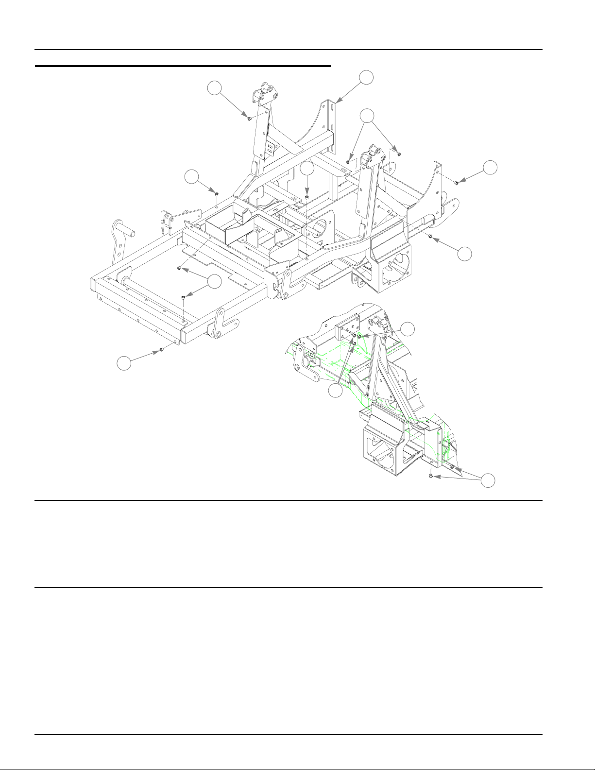
Tractor Frame Rivet Nut Installation
2
1
2
2
2
2
2
2
2
2
2
INDEX NO.
1 547067 382010 1 DIESEL Z TRACTOR FR A ME
2 N/A 808493 44 3/8-16 THREAD RIVET NUT
SERVICE
PART NO.
MFG. PART
NO.
QTY. DESCRIPTION
NOTES:
2-2 350702 4/05
2
Page 9
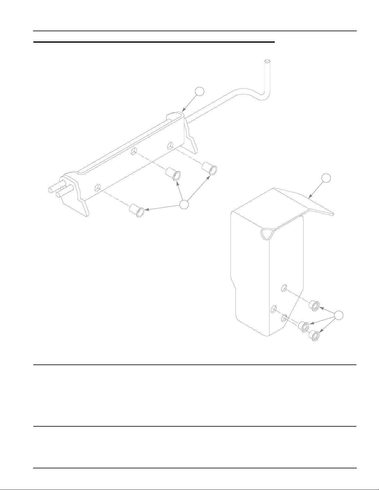
Seat Latch & Belt Guard Rivet Nut Installation
1
2
3
INDEX NO.
1 334060 334060 1 SEAT CATCH
2 808493 808493 6 3/8-16 THREAD RIVET NUT
3 352476 352476 1 FAN END BELT COVER
SERVICE
PART NO.
MFG. PART
NO.
QTY. DESCRIPTION
NOTES:
350702 4/05 2-3
2
Page 10
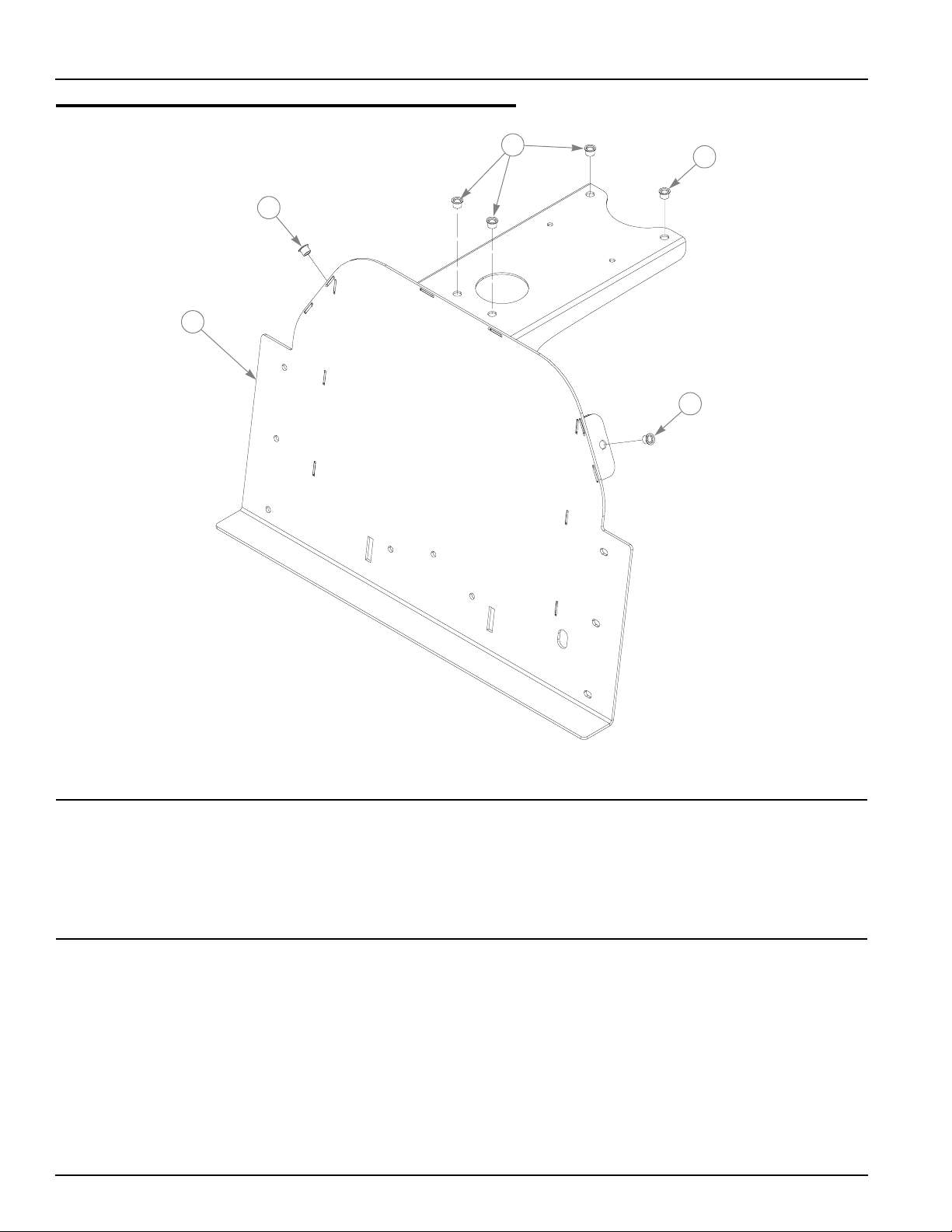
Seat Support Rivet Nut Installation
2
2
2
1
2
INDEX NO.
1 333492 333492 1 SEAT SUPPORT
2 808493 808493 6 3/8-16 THREAD RIVET NUT
SERVICE
PART NO.
MFG. PART
NO.
QTY. DESCRIPTION
2-4 350702 4/05
Page 11

Cooling System Rivet Nut Installation
1
3
2
INDEX NO.
1 101402 791939 1 COOLER PACKAGE
1
2 338996 338996 1 OVERFLOW BOTTLE MOUNT
3 N/A 808493 12 3/8-16 THREAD RIVET NUT
SERVICE
PART NO.
MFG. PART
NO.
1. Service part includes rivet nuts.
3
3
QTY. DESCRIPTION
NOTES:
350702 4/05 2-5
Page 12
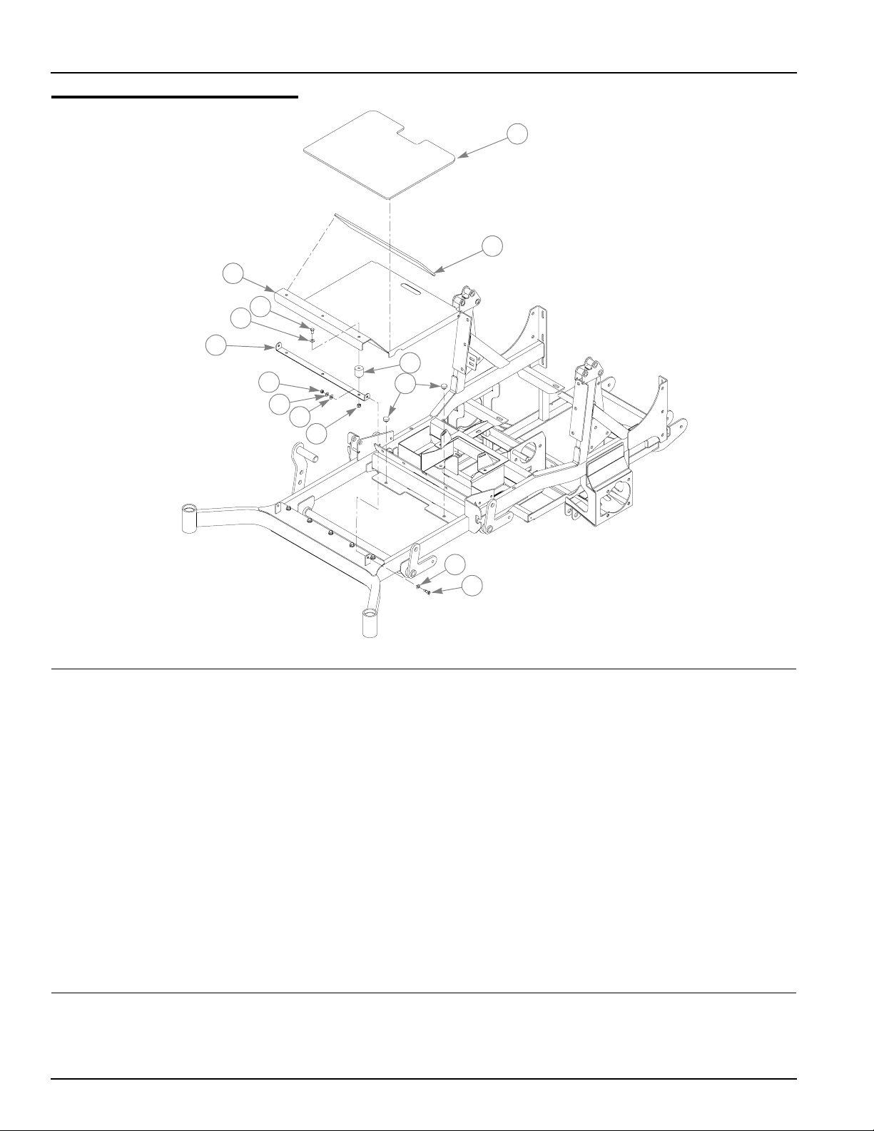
Foot Rest Assembly
3
4
5
6
7
8
1
2
9
11
5
10
5
12
INDEX NO.
1 795104 795104 1 FOOTPAN HORIZONTAL SOUNDMAT
2 795088 795088 1 FOOTPAN VERTICAL SOUNDMAT
3 314633 314633 1 FLOORPLATE
4 056069 056069 3 CS .375-16 X .625 HX G5 ZN
5 767954 767954 7 FW .406 X .812 X .060 SAE HD ZN
6 314716 314716 1 PIVOTING SUPPORT
7 058776 058776 2 NT .312-18 HX NL ZNYC
8 713685 713685 2 FW .312 X .75 X .06 ZNYC
9 796276 796276 3 3/8 M/F ROUND VIBRATION MOUNT
10 086660 086660 3 NT .375-16 HX LK NY
11 781880 781880 2 BUMPER
SERVICE
PART NO.
063297 063297 2 SB .375 X .500 SH .312-18 TD ZN
MFG. PART
NO.
QTY. DESCRIPTION
NOTES:
2-6 350702 4/05
Page 13

Chapter 3 Contents
Hydraulic Component Fittings . . . . . . . . . . . . . . . . . . . . . . . . . . . . . . 3-2
Hydraulic Component Mounting . . . . . . . . . . . . . . . . . . . . . . . . . . . . 3-2
Hydraulic Line Connections. . . . . . . . . . . . . . . . . . . . . . . . . . . . . . . . 3-6
350702 4/05 3-1
Page 14
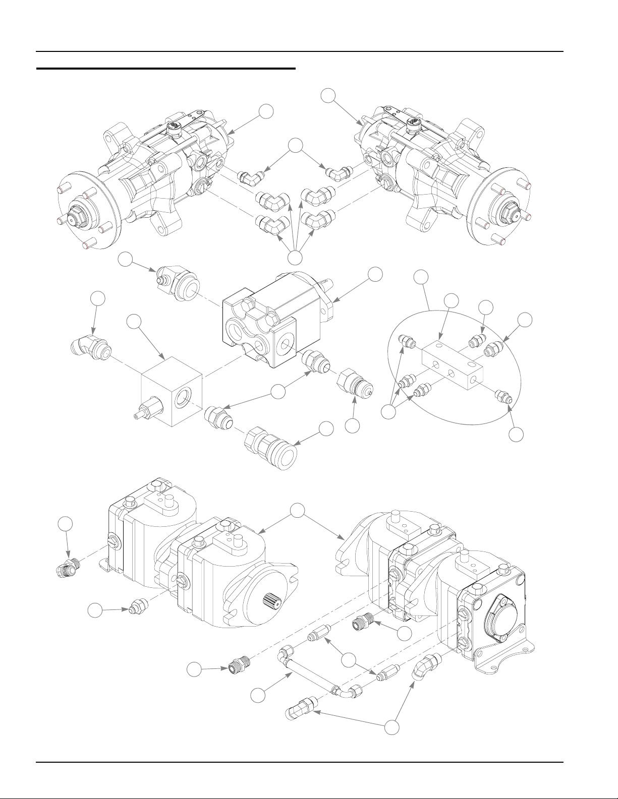
Hydraulic Component Fittings
1
2
3
15
7
8
6
4
5
9
13
11
10
16
21
12
13
14
13
17
18
19
18
20
4
3-2 350702 4/05
Page 15

Hydraulic Component Fittings
INDEX NO.
1 792069 792069 1 WHEEL MOTOR, PDM RH PORTS
2 794743 794743 1 WHEEL MOTOR, PDM LH PORTS
3 795922 N/A 2 FITTING, 90-6MORB/-6MJIC
1
4 781542 N/A 6 FITTING, 90-8MORB/-8MSL
1
5 793877 793877 1 PERMCO PUMP
6 793752 793752 1 VALVE ASSEMBLY-DIESEL
7 795401 795401 1 FITTING, T 20MORB.12MJIC.6MJ IC
8 796144 N/A 1 FITTING, 45-12MORB/-12MJIC
1
9 795930 N/A 2 FITTING, STR - 12MORB/-12MJI C
1
10 796110 N/A 1 FITTING,QC-12FORB/-12F
1
11 796128 N/A 1 FITTING,QC-12FORB/-12M
1
12 796284 N/A 1 CASE DRAIN MANIFOLD
2
13 779132 N/A 5 FITTING, STR-6MORB/-6JIC
2
14 796706 N/A 1 FITTING, STR-6MORB/-8MORB
2
15 771311 N/A 1 FITTING, 90-8MORB/-8MJIC
1
16 792200 792200 1 HYDRO-GEAR TANDOM PUMP
17 795914 N/A 1 FITTING, STR-6MJIC/-8MORB
1
18 781534 N/A 2 FITTING, STR-8MORB/-8MSL
1
19 771303 N/A 2 FITTING, STR-4MORB/-6MJIC
1
20 796060 N/A 1 HOSE,LP PUMP TO PUMP
1
21 796292 N/A 1 CASE DRAIN MANIFOLD
1
SERVICE
PART NO.
MFG. PART
NO.
QTY. DESCRIPTION
NOTES:
1. Included in 794727 Hydraulic Kit.
2. Included in Item 21 (796292 Case Drain Manifold)
350702 4/05 3-3
Page 16
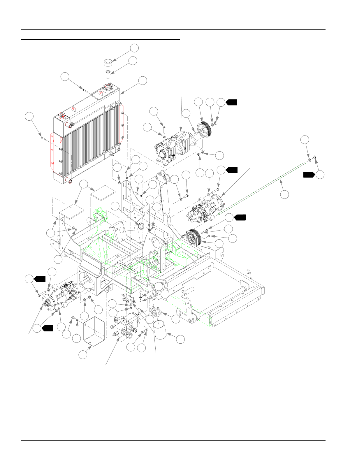
Hydraulic Component Mounting
1
2
4
4
23
25
32
23
21
23
3
22
6
12
24
TRANSPORT
PUMPS
8
9
5
11
11
7
13
12
11
11
17
10
14
1
LEFT SIDE
WHEEL MOTOR
1
2
20
19
18
16
11
1
15
24
11
1
14
11
1
15
LEFT SIDE
WHEEL MOTOR
26
22
21
6
12
11
6
27
28
DECK
PUMP
26
29
6
MANIFOLD
30
31
3-4 350702 4/05
Page 17

Hydraulic Component Mounting
INDEX NO.
1 032763 032763 1 BREATHER CAP
2 032771 032771 1 STRAINER
3 791939 791939 1 COOLER PACKAGE
4 050161 050161 6 CS .312-18 X 1.75 HX G5 ZNYC
5 056036 056036 2 CS .375-16 X 2.25 HX G5 ZNYC
6 767954 767954 8 FW .406 X .812 X .060 SAE HD ZN
7 712372 712372 1 1/4 SQ X 0.66 LONG KEY
8 794263 794263 1 8 GROOVE MIRCO V PULLEY
9 028118 028118 1 FW .625 X 1.00 X .134 ZNYC
10 021634 021634 1 NT .625-18 HX PN
11 767962 767962 16 FW .531 X 1.063 X .090 SAE HD ZN
12 781567 781567 6 NT .50-13 HX LK NY ZNYC
13 074252 074252 2 CS .500-13 X 1.50 HX G5 ZNYC
14 721910 721910 4 CS .500-13 X 2.75 HX G5 ZNYC
15 795153 795153 4 NT .50-13 SERRATED HX FLANGE
16 794958 794958 2 AT,1/2-13 X 42.00" B7 ZINC
17 794438 794438 1 DECK PUMP CLUTCH
18 016147 016147 4 CS .250-20 X .750 HXFLK ZNYC
19 795492 795492 1 FW .32 X .875 X .187
20 795518 795518 1 CS .312-24 X 1.50 HX W/ LK PATCH
21 029868 029868 2 CS .250-20 X .625 HXFLK ZNYC
22 782029 782029 2 LW .250 INT-EXT TOOTH Z
23 712927 712927 12 FW .344 X 1.00 X .12 HRD ZNYC
24 058776 058776 6 NT .312-18 HX NL ZNYC
25 795567 795567 3 DIESEL Z FUEL TANK FOAM
26 029751 029751 4 CS .375-16 X 1.00 HXFLK ZNYC
27 350850 350850 1 FILTER GUARD
28 086660 086660 2 NT .375-16 HX LK NY
29 015719 015719 1 WOODRUFF .156X.625 SAE# 6
30 783928 783928 1 FILTER HEAD ZAF SERIES
31 783936 783936 1 FILTER ELEMENT
32 796367 796367 1 1.625 X 2.00 X .188 RUBBER GROMMET
SERVICE
PART NO.
MFG. PART
NO.
QTY. DESCRIPTION
NOTES:
1. Torque to 75 ft. lbs.
2. Torque to 25-28 ft. Lbs.
3. Hydraulic system capacity: Fill reservoir to 3.5" below top of fill neck—12
Qts.
4. Electric clutch burnishing procedure: With engine at half throttle—
approximately 2400 RPM—engage clutch for 15 seconds, then
disengage for 15 seconds for 10 cycles.
350702 4/05 3-5
Page 18
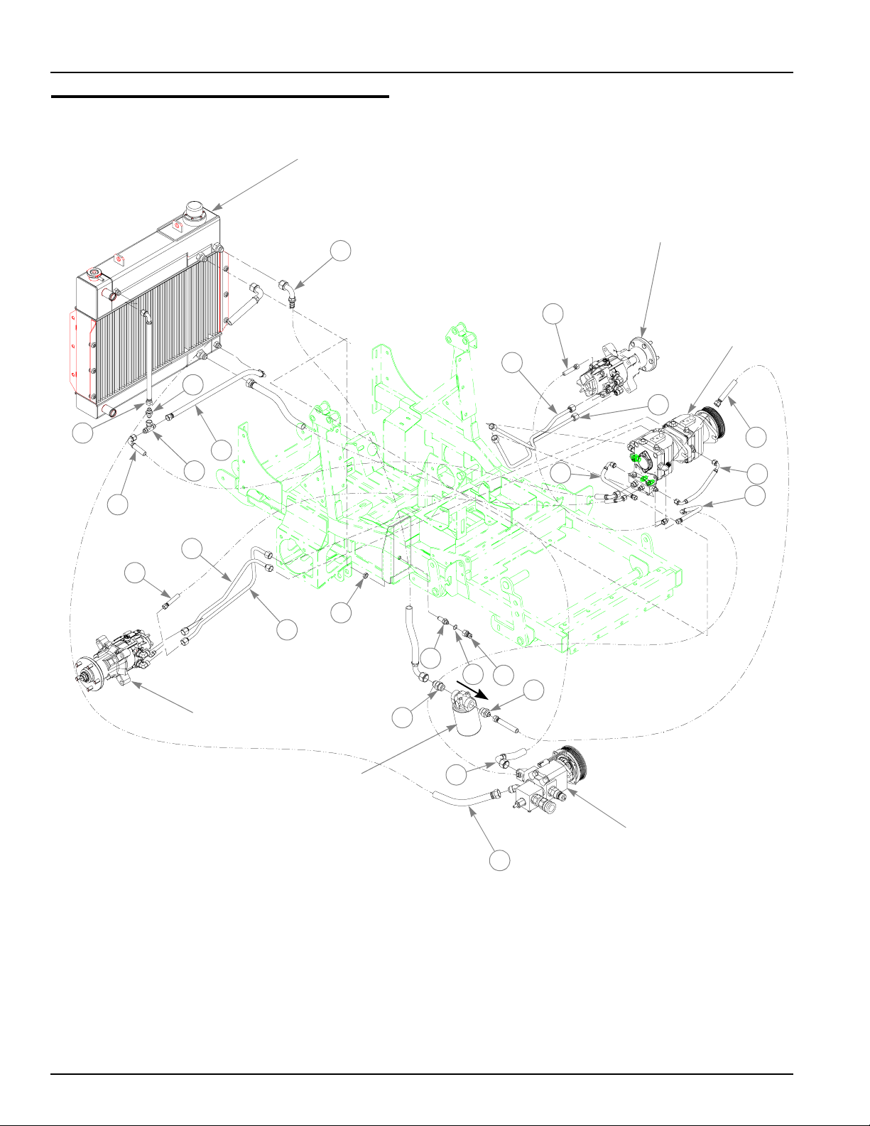
Hydraulic Line Connections
COOLER PACKAGE
5
LEFT WHEEL
MOTOR
10
1
9
8
6
12
11
7
3
RIGHT WHEEL
MOTOR
17
4
18
19
20
21
16
22
TRANSPORT
PUMPS
2
13
14
15
OIL FILTER
ASSEMBLY
WITH OIL FLOW
IN ARROW DIRECTION
3-6 350702 4/05
23
DECK
PUMP
24
Page 19

Hydraulic Line Connections
INDEX NO.
1 795856 N/A 1 MOTOR TO PUMP TUBE
2 795872 N/A 1 MOTOR TO PUMP TUBE
3 796185 N/A 1 MOTOR TO PUMP TUBE
4 796193 N/A 1 MOTOR TO PUMP TUBE
5 796086 N/A 1 HOSE,LP COOLER TO FILTER
6 796771 N/A 1 HOSE
7 796789 N/A 1 FITTING
8 796821 N/A 1 HOSE
9 796797 N/A 1 RELIEF VALVE, 10PSI -8MJIC/-8MJIC
10 796011 N/A 1 HOSE,LP CASE-DRAIN LH MT R
11 796029 N/A 1 HOSE,LP CASE-DRAIN RH MTR
12 796052 N/A 1 HOSE,LP CASE-DRAIN RES
13 796102 N/A 1 HOSE,LP FILTER TO PUMP
14 796045 N/A 1 HOSE,LP CASE-DRAIN PUMP
15 796078 N/A 1 HOSE
16 796037 N/A 1 HOSE,LP CASE-DRAIN BH
17 795989 N/A 1 NT-6 BULKHEAD
18 795971 N/A 1 FITTING,STRBH-6MJIC/-6MJIC
19 795997 N/A 1 06 O-RING
20 796003 N/A 1 FITTING, QC-6FORB/-6M
21 795930 N/A 1 FITTING, STR - 12MORB/-12MJI C
22 796151 N/A 1 FITTING,STR-8MJIC/-12MORB
23 796177 N/A 1 HOSE,LP COOL ER TO PUMP
24 796169 N/A 1 HOSE,LP VALVE TO COOLER
SERVICE
PART NO.
MFG. PART
NO.
QTY. DESCRIPTION
NOTES:
1. All parts included with 794727 Diesel Z Tractor Hydro Kit.
350702 4/05 3-7
Page 20

3-8 350702 4/05
Page 21

Chapter 4 Contents
Battery Installation. . . . . . . . . . . . . . . . . . . . . . . . . . . . . . . . . . . . . . . 4-2
Deck Lift Assembly . . . . . . . . . . . . . . . . . . . . . . . . . . . . . . . . . . . . . . 4 -4
Steering and Park Brake Assembly. . . . . . . . . . . . . . . . . . . . . . . . . . 4-6
350702 4/05 4-1
Page 22
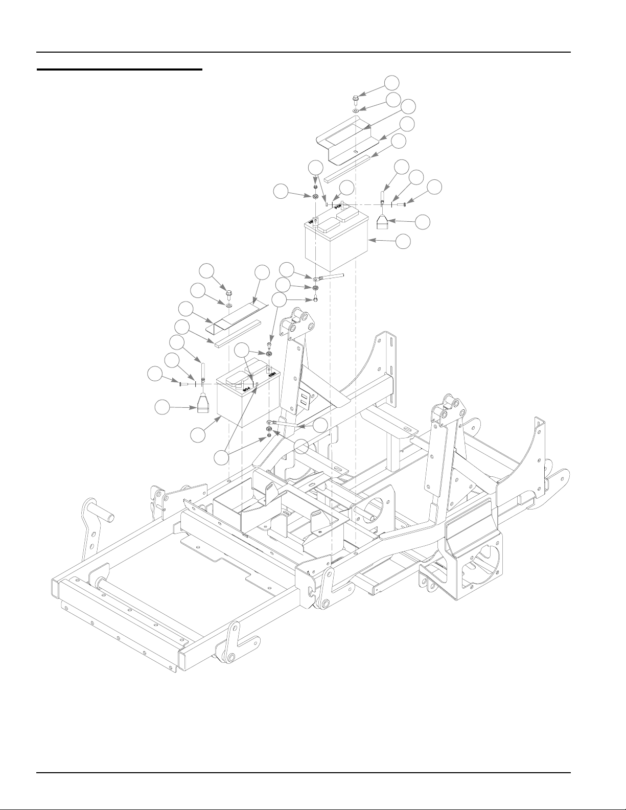
Battery Installation
1
2
4
3
5
9
7
1
2
3
5
13
7
6
10
11
7
9
12
4
7
6
7
7
14
8
7
6
10
11
4-2 350702 4/05
Page 23

Battery Installation
INDEX NO.
1 029751 029751 2 CS .375-16 X 1.00 HXFLK ZNYC
2 767954 767954 2 FW .406 X .812 X .060 SAE HD ZN
3 351288 351288 2 BATTERY COVER
4 722199 722199 2 2" WIDE SCOTCH POLYURETHANE
5 713198 713198 2 SEAL 3/8 X 3/4 X 8.50 LG
6 016154 016154 4 CS .250-20 X 1.00 HXFLK ZNYC
7 029868 029868 8 LW .250 INT-EXT TOOTH ZNYC
8 793216 793216 1 24" POSITIVE BATTERY CABLE
9 024927 024927 4 NT .250-20 HX GR.5 ZNYC
10 771428 771428 2 RED BATTERY CABLE BOOT
11 740696 740696 2 BATTERY VU1LH-8
12 796219 796219 1 36" NEGATIVE BATTERY CABLE
13 786632 786632 1 30" POSITIVE BATTERY CABLE
14 785071 785071 1 NEGATIVE BATTERY CABLE
SERVICE
PART NO.
MFG. PART
NO.
QTY. DESCRIPTION
NOTES:
1. When performing service on mower, disconnect battery ground cables
and do not reconne ct to batteries unt il engine is rea dy to be started. Se e
Owners Manual.
350702 4/05 4-3
Page 24
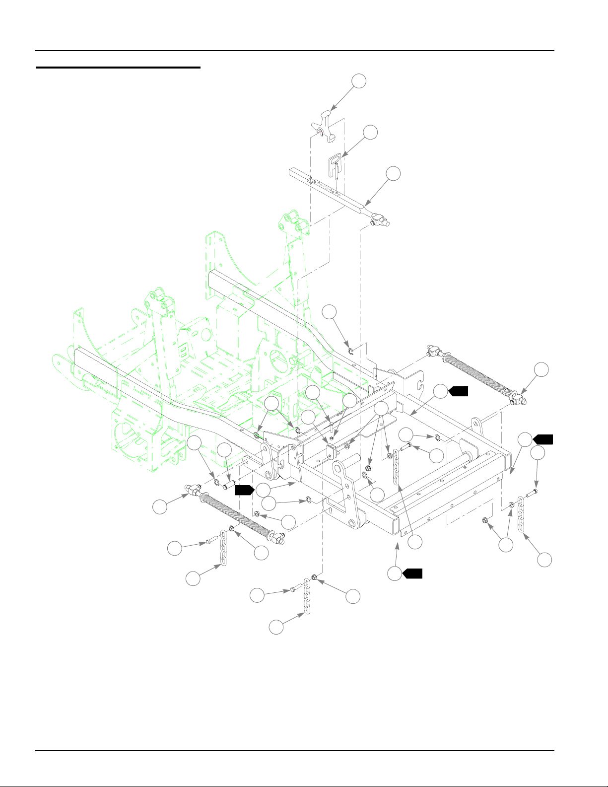
Deck Lift Assembly
1
2
3
4
14
14
1
11
1
13
9
1
13
9
8
11
5
4
7
4
12
1
13
4
8
9
11
8
10
11
6
8
4
4
13
8
4-4 350702 4/05
Page 25

Deck Lift Assembly
INDEX NO.
1 348318 348318 1 STOP HANDLE
2 348284 348284 1 HEIGHT ADJUSTMENT STOP
3 783001 783001 1 DECK LIFT INDICATOR
4 781294 781294 7 E CLIP, 1.00 X.625X .050
5 756270 756270 1 CS .312-18 X 1.50 FLTHR GR5 ZNYC
6 034272 034272 1 NT .312-18 HX G5 ZNYC
7 348458 348458 1 DECK LEVELER YOKE
8 704643 704643 8 NT .437-14 HX FLG ZN
9 055749 055749 3 CS .437-14 X 1.75 HX G5 ZNYC
10 781831 781831 1 CS .437-14 X 1.75 FULTH G5 ZNYC
11 348391 348391 4 DECK LIFT CHAIN
12 781229 781229 1 CE .750 X 2.25 X 1.75 HEADLESS
13 015495 015495 4 STRAIGHT GREASE FITTING
14 782995 782995 2 DECK LIFT SPRING
SERVICE
PART NO.
MFG. PART
NO.
QTY. DESCRIPTION
NOTES:
1. Apply grease at zerks, see owner’s manual.
350702 4/05 4-5
Page 26
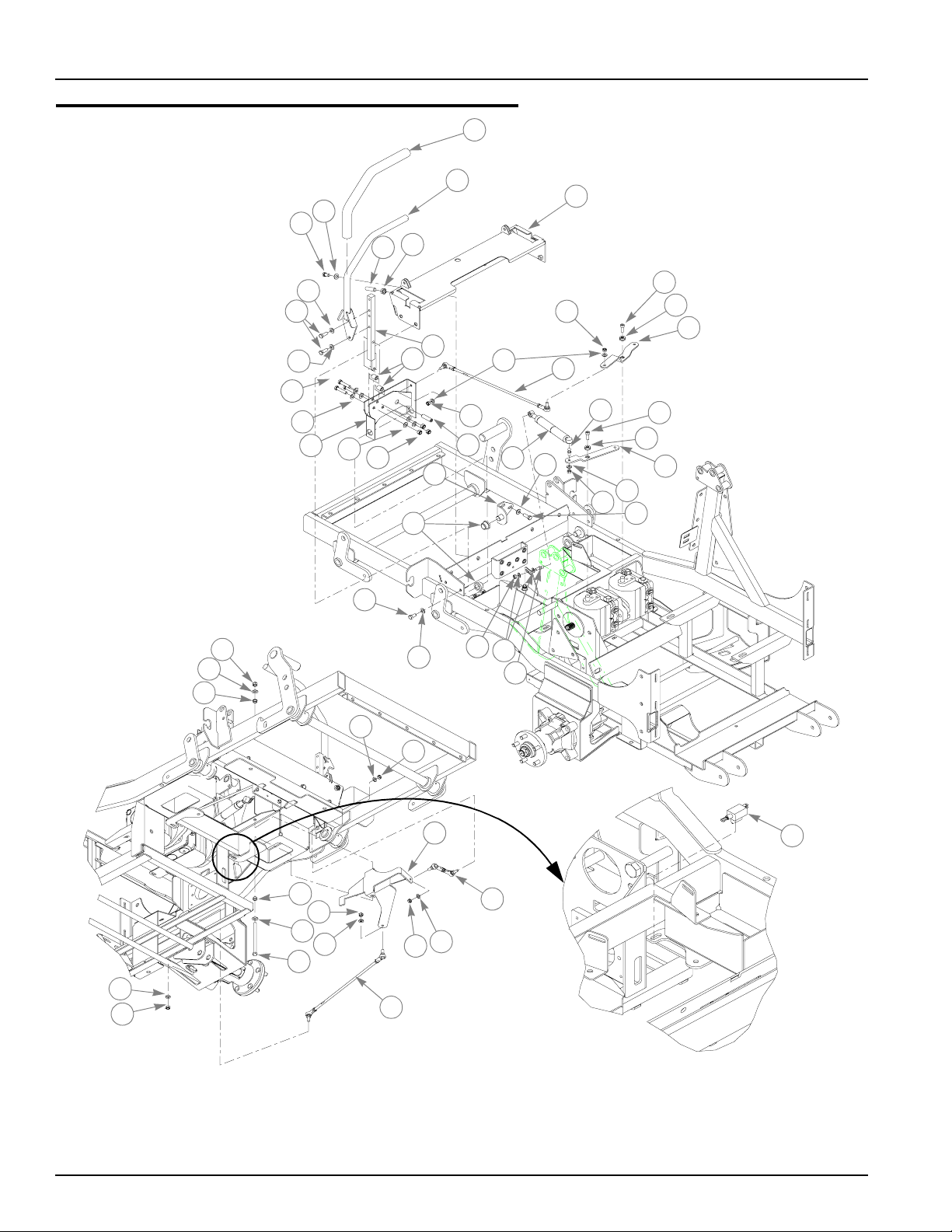
Steering and Park Brake Assembly
1
2
5
4
7
6
3
26
5
8
9
5
{
12
5
11
13
5
{
5
15
10
{
{
13
24
25
4
5
30
14
6
23
15
22
15
21
14
20
21
5
23
16
17
18
16
17
19
15
8
15
14
26
27
28
14
5
15
20
30
15
29
4-6 350702 4/05
31
Page 27

Steering and Park Brake Assembly
INDEX NO.
1 781260 781260 2 STEERING BAR GRIP
2 348755 348755 2 STEERING BAR
3 348987 348987 1 STEERING CONTROL PANEL
4 055822 055822 8 CS .375-16 X .75 HX G5 ZNYC
5 767954 767954 3 FW .406 X .812 X .060 SAE HD ZN
6 781716 781716 4 SS .500-13 X 2.00 SH ZNYC
7 053199 053199 2 NT .500-13 HX JAM ZNYC
8 036244 036244 10 CS .375-16 X 1.00 HX G5 ZNYC
9 348946 348946 2 STEERING ARM MOUNT
10 348862 348862 4 STEERLEVER BUSHING
11 348888 348888 1 LEFT STEERLEVER SUPPOR T
12 705178 705178 6 CS .375-16 X 1.75 HX G5 ZNYC
13 086660 086660 8 NT .375-16 HX LK NY
14 023655 023655 8 NT .312-24 HX NL ZNYC
15 768523 768523 12 FW .343 X .687 X .051/.080 HD ZNYC
16 795377 795377 2 CS M 8-1.25 X 25 SH BO NYLK
17 795369 795369 2 HYDRO GEAR PUMP ARM RETAINER
18 333344 333344 1 RIGHT SIDE PUM P AR M
19 333351 333351 1 LEFT SIDE PUMP ARM
20 781286 781286 4 PUMP ROD ADJUSTER ASSEMBLY
21 781922 781922 4 DAMPER BALL STUD
22 795351 795351 2 STEERING DAMPER
23 034272 034272 4 NT .312-18 HX G5 ZNYC
24 348797 348797 2 ADJUSTABLE PIVOT
25 781153 781153 4 BUSHING
26 765339 765339 4 IGUS#MFI-0608_05 BUSHING
27 748913 748913 2 CS .375-16 X 5.50 GR5 ZN
28 351171 351171 1 LEFT BRAKE ARM
29 781583 781583 2 BRAKE ROD ASSEMBLY
30 041152 041152 4 NT .312-24 HX ZNYC
31 795625 795625 2 SNAP MOUNT PLUNG E R SW ITCH
SERVICE
PART NO.
348714 348714 1 RIGHT STEERLEVER SUPPORT
351168 351168 1 RIGHT BRAKE ARM
MFG. PART
NO.
QTY. DESCRIPTION
NOTES:
350702 4/05 4-7
Page 28

4-8 350702 4/05
Page 29

Chapter 5 Contents
Engine Idler . . . . . . . . . . . . . . . . . . . . . . . . . . . . . . . . . . . . . . . . . . . . 5-2
Air Cleaner Breakdown . . . . . . . . . . . . . . . . . . . . . . . . . . . . . . . . . . . 5-3
Seat Support Assembly. . . . . . . . . . . . . . . . . . . . . . . . . . . . . . . . . . . 5-4
Cooler Assembly . . . . . . . . . . . . . . . . . . . . . . . . . . . . . . . . . . . . . . . . 5-6
Muffler Assembly . . . . . . . . . . . . . . . . . . . . . . . . . . . . . . . . . . . . . . . . 5-7
Engine Assembly. . . . . . . . . . . . . . . . . . . . . . . . . . . . . . . . . . . . . . . . 5 -8
Engine Installation. . . . . . . . . . . . . . . . . . . . . . . . . . . . . . . . . . . . . . 5-10
Fuel Tank Assemblies . . . . . . . . . . . . . . . . . . . . . . . . . . . . . . . . . . . 5-12
Fuel System Installation. . . . . . . . . . . . . . . . . . . . . . . . . . . . . . . . . . 5-14
Instrument Panel Assembly. . . . . . . . . . . . . . . . . . . . . . . . . . . . . . . 5-16
Electrical Schematic—795336. . . . . . . . . . . . . . . . . . . . . . . . . . . . . 5-18
Electrical Schematic—795831. . . . . . . . . . . . . . . . . . . . . . . . . . . . . 5-20
350702 4/05 5-1
Page 30

Engine Idler
1
5
1
2
3
4
INDEX NO.
1 335638 335638 1 ARM IDLER
2 792275 792275 1 IDLER BACKSIDE PULLEY
3 028118 028118 1 FW .625 X 1.00 X .134 ZNYC
4 016642 016642 1 CS .625-11 X 2.00 HX G5 ZNY C
5 015495 015495 1 STRAIGHT GREASE FITTING
SERVICE
PART NO.
1. Apply grease to zerk.
MFG. PART
NO.
QTY. DESCRIPTION
NOTES:
5-2 350702 4/05
Page 31

Air Cleaner Breakdown
1
2
3
3
4
5
6
7
4
8
INDEX NO.
1 775353 775353 1 CENTRIFICAL PRECLEANER
2 057661 N/A 1 HOSE CLAMP
1
3 795138 795138 1 AIR FILTER INDICATOR
4 782763 782763 1 AIR CLEANER
5 785279 785279 1 AIR FILTER SAFETY ELEMENT
6 785261 N/A 1 AIR FILTER MAIN ELEMENT
2
7 785741 785741 1 MOUNTING BAND
8 763318 N/A 1 VACUATOR VALVE
2
SERVICE
PART NO.
MFG. PART
NO.
QTY. DESCRIPTION
NOTES:
1. Included with Item 1 (775353 Centrifical Precleaner).
2. Included with item 4 (782763 Air Cleaner).
3. Orient outlet of precleaner to rear of mower as shown.
350702 4/05 5-3
Page 32

Seat Support Assembly
1
2
AIR CLEANER
10
11
10
4
5
2
3
8
SEAT SUPPORT
6
5
4
12
13
SEAT LATCH
4
5
4
5
9
SEAT SUPPORT
5-4 350702 4/05
7
5
4
Page 33

Seat Support Assembly
INDEX NO.
1 079186 079186 2 CS .312-18 X 1.25 HX G5 ZNYC
2 768523 768523 4 FW .343 X .687 X .051/.080 HD ZNYC
3 058776 058776 2 NT .312-18 HX NL ZNYC
4 029751 029751 9 CS .375-16 X 1.00 HXFLK ZNYC
5 767954 767954 9 FW .406 X .812 X .060 SAE HD ZN
6 335133 335133 1 DIESEL Z LEFT SIDE HOOD
7 334987 334987 1 DIESEL Z RIGHT SIDE HOOD
8 795716 795716 1 LEFT SIDE ENGINE COVER FOAM
9 795708 795708 1 RIGHT SIDE ENGI N E COVER FOAM
10 795542 795542 1 FUEL VALVE
11 795294 795294 1 SEAT SUPPORT SOUNDMAT
12 795724 795724 1 INNER SEAT SUPPORT CENTER FOAM
13 795583 795583 1 TORSION SPRING
SERVICE
PART NO.
MFG. PART
NO.
QTY. DESCRIPTION
NOTES:
350702 4/05 5-5
Page 34

Cooler Assembly
1
2
3
COOLER PACKAGE
4
9
5
7
8
6
14
6
5
6
10
7
12
13
8
14
6
10
15
8
11
INDEX NO.
1 791400 791400 1 HOSE 36" LONG
2 041491 041491 1 HOSE CLAMP
3 076919 N/A 1 RADIATOR CAP—14 ±2 LB
4 713198 713198 1 SEAL 3/8 X 3/4 28" LONG
5 068551 068551 8 NT .250-20 HX NL ZNYC
6 017079 017079 16 FW .250 X .560 X .04 SAE ZNYC
7 059832 059832 4 NT #10-24 HX NL ZN
8 035691 035691 8 FW .210 X .500 X .046 ZNYC
9 344598 344598 1 SHROUD
10 055939 055939 8 CS .250-20 X .750 HX G5 ZNYC
11 714998 714998 4 MS #10-24 X .625 HX ZN
12 029751 029751 6 CS .375-16 X 1.00 HXFLK ZNYC
13 767954 767954 6 FW .406 X .812 X .060 SAE HD ZN
14 792812 792812 2 ELECTRIC COOLING FAN (16")
15 795500 795500 2 FAN REVERSAL SWITCH
SERVICE
PART NO.
MFG. PART
NO.
QTY. DESCRIPTION
NOTES:
5-6 350702 4/05
Page 35

Muffler Assembly
1
2
INDEX NO.
1 102558 1 SDZ MUFFLER KIT
1
2 N/A 808493 3 RIVET NUT, 3/8-16 THREAD
SERVICE
PART NO.
MFG. PART
NO.
QTY. DESCRIPTION
NOTES:
1. Kit includes muffler with rivet nuts in stalle d, 10196 4 (SDZ M uffle r Mount)
and hardware required for installation.
350702 4/05 5-7
Page 36

Engine Assembly
4
2
3
2
5
2
5
2
8
8
8
3
2
6
31
11
10
10
1
12
MUFFLER
ASSEMBLY
25
26
2
7
11
8
13
27
14
2
7
23
29
24
9
1
16
15
3
17
18
16
19
22
21
4
20
10
32
10
16
4
20
21
30
19
16
28
5-8 350702 4/05
17
3
Page 37

Engine Assembly
INDEX NO.
1 792143 792143 1 CATERPILLER 3013C ENGINE
2 101964 101964 1 MUFFLER MOUNT
3 767954 767954 4 FW .406 X .812 X .060 SAE
4 029751 029751 3 CS .375-16 X 1.00 HXFLK
5 720516 720516 2 CS M8 X 1.25 X 16 G10.9 HX
6 720110 720110 1 CS M10-1.5 X 20 10.9 HXFL
7 720177 720177 6 CS M 8-1.25 X 20 10.9 HX FL ZNYC
8 796540 796540 8 LW .312 NORD-LOCK NL8
9 795765 795765 1 CAT 3013C EXHAUST GASKET
10 713040 713040 4 HOSE CLAMP
11 057661 057661 2 HOSE CLAMP
12 792432 792432 1 DIESEL Z AIR CLEANER HO SE
13 794271 794271 1 8 GROOVE MIRCO V PULLEY
14 767962 767962 3 FW .531 X 1.063 X .090 SAE HD ZN
15 794164 794164 3 CS M12-1.75 X 70 HX FL ZNYC
16 712919 712919 8 FW .406 X 1.00 X .12 HRD ZNYC
17 016410 016410 4 CS .375-16 X 2.00 G5 ZNYC
18 314682 314682 1 RIGHT SIDE FRONT ENGINE MOUNT
19 086660 086660 4 NT .375-16 HX LK NY
20 793729 793729 8 M14-1.50 X 30 ZNYC
21 028118 028118 8 FW .625 X 1.00 X .134 ZNYC
22 330670 330670 1 FAN END ENGINE MOUNT
23 338962 338962 1 THROTTLE CABLE SUPPORT
24 739144 739144 2 CS M 6-1.0 X 12 10.9 HXFL ZN
25 060731 060731 1 CS 10-24 X .500 HXFLK ZNYC
26 011841 011841 1 CONDUIT CLIP
27 346957 346957 1 THROTTLE CABLE PIN
28 314666 314666 1 LEFT SIDE FRONT ENGINE MOUNT
29 017079 017079 2 FW .250 X .560 X .04 SAE ZNYC
30 314641 314641‘ 1 FAN END ALTERNATOR SIDE ENGINE MOUNT
31 792416 792416 1 UPPER RADIAT OR HOSE
32 792424 792424 1 LOWER RADIATOR HOSE
SERVICE
PART NO.
MFG. PART
NO.
QTY. DESCRIPTION
NOTES:
1. Torque to 55 ft. lbs.
2. Torque to 30 ft.-lbs.
3. Torque to 48 ft. lbs.
4. Torque to 80 ft. lbs.
350702 4/05 5-9
Page 38

Engine Installation
Seat Support Assembly
13
14
ENGINE ASSEMBLY
2
1
1
3
1
4
1
3
4
2
6
ENGINE IDLER
COOLER ASSEMBLY
5
6
10
11
12
8
9
22
3
6
7
6
2
23
2
2
3
2
17
2
15
7
TRACTOR FRAME
2
21
20
16
18
5
18
19
4
5-10 350702 4/05
Page 39

Engine Installation
INDEX NO.
1 029751 029751 12 CS .375-16 X 1.00 HXFLK ZNYC
2 767954 767954 12 FW .406 X .812 X .060 SAE HD ZN
3 721910 721910 4 CS .500-13 X 2.75 HX G5 ZNYC
4 344267 344267 4 FW .510 X 2.15 X .187 SPL ZNYC
5 792366 792366 4 SHOCK MOUNT
6 767962 767962 8 FW .531 X 1.063 X .090 SAE HD ZN
7 781567 781567 4 NT .50-13 HX LK NY ZNYC
8 061101 061101 1 NT .750-10 HX NL ZN
9 025296 025296 A/R FW .760 X 1.625 X .08 ZNYC
10 792267 792267 1 8 GROOVE MIRCO V BELT
11 781302 781302 1 IDLER SPRING
12 373191 373191 1 SIDE MOUNT CHAIN
13 350876 350876 1 COOLER GUARD
14 781880 781880 4 BUMPER
15 704932 704932 1 FW .219 X .500 X .048 ZNYC
16 741132 741132 1 NT M5-0.8 HX ZN NYLOC
17 720219 720219 1 CS M 8-1.25 X 30 LG. HXFLG
18 076547 076547 2 FW .344 X .688 X .065 SAE ZNYC
19 782664 782664 1 NT M8-1.25 HX STAINLESS STEEL
20 044255 044255 1 NT #10-32 HX ZN
21 017079 017079 1 FW .250 X .560 X .04 SAE ZNYC
22 795336 795336 1 WIRE HARNESS
23 795831 795831 1 DIESEL Z FANS WIRE HARNESS
SERVICE
PART NO.
MFG. PART
NO.
QTY. DESCRIPTION
NOTES:
1. Torque to 73 ft. lbs.
2. Part of Item 22 (795336 Wire Harness).
3. Part of Item 23 (795831 Diesel Z Fans Wire Harness).
4. To positive battery terminals.
5. To negative battery terminals.
6. Engine high RPM to be set at 3100±50 with transport pump load only.
7. Engine low idle RPM to be set at 1400±100 with transport pump load
only .
8. Engine oil capacity; 6.3 qts. including filter.
9. Engine coolant capacity; 2.8 gal.
350702 4/05 5-11
Page 40

Fuel Tank Assemblies
6
8
9
10
1
5
4
15
2
4
5
11
12
4
2
5
1
3
12
13
4
11
7
14
15
12
4
2
5
4
2
5
5-12 350702 4/05
Page 41

Fuel Tank Assemblies
INDEX NO.
1 779306 779306 2 3.5" FUEL CAP
2 792333 792333 1 LEFT SIDE FUEL TANK
3 792325 792325 1 RIGHT SIDE FUEL TANK
4 767954 767954 21 FW .406 X .812 X .060 SAE HD ZN
5 055822 055822 18 CS .375-16 X .750 HX G5 ZNYC
6 347666 347666 1 LEFT SIDE FUEL TANK SUPPORT
7 347625 347625 1 RIGHT SIDE FUEL TANK SUPPORT
8 338996 N/A 1 OVERFLOW BOTTLE MOUNT
9 761023 761023 1 2 QT. COOLANT BOTTLE
10 041491 041491 1 HOSE CLAMP
11 023143 023143 5 CS .250-20 X .500 HXFLK ZNYC
12 017079 017079 5 FW .250 X .560 X .04 SAE ZNYC
13 029751 029751 3 CS .375-16 X 1.00 HXFLK ZNYC
14 352476 N/A 1 FAN END BELT COVER
15 795567 795567 2 DIESEL Z FOAM
SERVICE
PART NO.
MFG. PART
NO.
QTY. DESCRIPTION
NOTES:
1. Service parts for fuel system not shown;
2. Torque to 20 ft. lbs.
785295 FUEL GROMMET
794107 FUEL SUCTION TUBE
794081 FUEL FILTER SCREEN
792986 SITE-LINE TANKS FUEL FITTING
794735 FUEL RETURN ASSEMBL Y
350702 4/05 5-13
Page 42

Fuel System Installation
LEFT SIDE
FUEL TANK
ASSEMBLY
1
5
1
2
14
9
3
12
11
10
11
10
RIGHT SIDE
FUEL TANK
ASSEMBLY
3
4
2
6
3
14
12
8
13
3
2
4
3
3
1
7
13
9
5-14 350702 4/05
Page 43

Fuel System Installation
INDEX NO.
1 795542 N/A 1 FUEL VALVE
2 041483 041483 2 HOSE CLAMP
3 000323 000323 8 HOSE CLAMP
4 041491 041491 2 HOSE CLAMP
5 038398 038398 1 FUEL HOSE, 29.5" LONG
6 791400 791400 1 FUEL LINE 33" LONG
7 015818 015818 1 FUEL LINE 15.5" LONG
8 015818 015818 1 FUEL LINE 16.5" LONG
9 015818 015818 2 FUEL LINE 53.5" LONG
10 767954 767954 8 FW .406 X .812 X .060 SAE HD ZN
11 029751 029751 8 CS .375-16 X 1.00 HXFLK ZNYC
12 785295 N/A 4 GROMMET
3
13 792986 N/A 2 FUEL FITTING SITE-LINE TANKS
3
14 794735 N/A 2 FUEL RETURN ASSEMBLY
3
16 796847 N/A 1 HOSE COVERING 12” LG (NOT SHOWN)
4
SERVICE
PART NO.
MFG. PART
NO.
QTY. DESCRIPTION
NOTES:
1. Connected to engine fuel rail fuel return.
2. Connected to engine fuel pump inlet.
3. Supplied with new fuel tank.
4. Fuel line, return fuel line and leads for fuel shut-off and oil pressure are
covered by this part.
350702 4/05 5-15
Page 44

Instrument Panel Assembly
1
2
4
5
6
9
10
1
11
7
8
5
8
3
7
8
1
11
9
8
1
11
12
1
2
1
13
8
15
7
8
9
10
30a
15 a
14
8
15 a
10 a
5-16 350702 4/05
Page 45

Instrument Panel Assembly
INDEX NO.
1 712257 712257 3 RED INDICATOR LIGHT
2 769166 769166 1 HOUR METER
3 795484 795484 1 PANEL MOUNT ROCKER SWITCH
4 083022 N/A 2 IGNITION KEY
5 045898 045898 1 KEY SWITCH
6 776476 776476 1 PTO SWITCH
7 714998 714998 6 MS #10-24 X .625 HX ZN
8 704932 704932 12 FW .219 X .500 X .048 ZNYC
9 059832 059832 6 NT #10-24 HX NL ZN
10 794347 794347 2 ULTRA LOUD WARBLE TONE ALARM
11 026237 N/A 6 RELAY
12 337477 337477 1 DIESEL INSTRUMENT PANEL
13 762195 N/A 1 DELAY MODULE
14 795328 795328 1 THROTTLE CONTROL
15 762070 762070 1 HANDLE
SERVICE
PART NO.
785808 785808 1 INDAK COATED KEY
MFG. PART
NO.
QTY. DESCRIPTION
NOTES:
1. Part of 795336 (Tractor Wire Harness)
350702 4/05 5-17
Page 46

Electrical Schematic—795336
5-18 350702 4/05
Page 47

Electrical Schematic—795336
350702 4/05 5-19
Page 48

Electrical Schematic—795831
5-20 350702 4/05
Page 49

Chapter 6 Contents
Front Axle Assembly . . . . . . . . . . . . . . . . . . . . . . . . . . . . . . . . . . . . . 6-2
Front Wheel Breakdown—791897. . . . . . . . . . . . . . . . . . . . . . . . . . . 6-4
Drive Wheel Assembly Installation . . . . . . . . . . . . . . . . . . . . . . . . . . 6-5
Anti-Rollover Wheel Assembly . . . . . . . . . . . . . . . . . . . . . . . . . . . . . 6-6
350702 4/05 6-1
Page 50

Front Axle Assembly
1
2
3
4
3
5
6
3
5
14
15
1
2
3
4
11
10
7
14
15
3
5
8
13
10
2
9
10
6
3
5
7
8
10
11
1
12
1
12
6-2 350702 4/05
Page 51

Front Axle Assembly
INDEX NO.
1 705954 705954 2 CS .500-13 X 1.25 HX G5 ZNYC
2 344267 344267 2 FW .510 X 2.15 X .187 SPL ZNYC
3 712976 712976 2 FW .531 X 1.375 X .125 ZNYC
4 263517 263517 2 BEARING DISC
5 784223 784223 4 BEARING
6 387035 387035 2 SPACER, 1.07 X 1.312 X 2.793
7 045765 045765 2 FW 1.030 X 1.500 X .134 ZNYC
8 311969 311969 2 FORK
9 061101 061101 2 NT .750-10 HX NL ZN
10 025296 025296 4 FW .760 X 1.625 X .08 ZNYC
11 041475 041475 2 CS .750-10 X 9.50 HX ZNYC
12 791897 791897 2 WHEEL/TIRE ASSEMBLY
13 314518 314518 1 AXLE 72"
14 029751 029751 10 CS .375-16 X 1.00 HXFLK ZNYC
15 767954 767954 10 FW .406 X .812 X .060 SAE HD ZN
SERVICE
PART NO.
314500 314500 1 AXLE 60"
MFG. PART
NO.
QTY. DESCRIPTION
NOTES:
1. Apply grease to zerk (see owner’s manual).
2. Torque to 100 ft. lbs.
3. Assemble w i th extended inner race toward item 6 (387035 Spacer,
1.07x 1.312 x 2.793)
350702 4/05 6-3
Page 52

Front Wheel Breakdown—791897
1
2
1
3
4
1
6
5
INDEX NO.
1 039677 N/A 2 WHEEL BEARING
2 791913 N/A 1 15 X 6.00-6 4 PLY TIRE
3 747832 N/A 1 6 X 4.5 WHEEL
4 782771 N/A 1 BEARING SPACER
5 015511 N/A 1 45° DEG ¼" GREASE FITTING
6 019521 N/A 1 TIRE VALVE
SERVICE
PART NO.
1. Inflate tire to 8–10 psi.
MFG. PART
NO.
QTY. DESCRIPTION
NOTES:
6-4 350702 4/05
Page 53

Drive Wheel Assembly Installation
1
3
1
4
2
2
5
INDEX NO.
1 791871 791871 2 WHEEL/TIRE ASSY FOR 72" (QTY PER TRACTOR)
2 747899 N/A TIRE 26X12X12
3 784066 N/A WHEEL ASSY 12 X 8.50 FOR 72"
4 061077 061077 10 WHEEL NUT (QTY PER TRACTOR)
5 019521 N/A 1 TIRE VALVE
1 791889 791889 2 WHEEL/TIRE ASSY FOR 60" (QTY PER TRACTOR)
2 747899 N/A TIRE 26X12X12
3 781252 N/A WHEEL ASSY 12 X 8.50 FOR 60"
4 061077 061077 10 WHEEL NUT (QTY PER TRACTOR)
5 019521 N/A 1 TIRE VALVE
SERVICE
PART NO.
1. Torque to 65–75 ft. lbs.
2. Inflate tire to 8–10 psi.
MFG. PART
NO.
QTY. DESCRIPTION
NOTES:
350702 4/05 6-5
Page 54

Anti-Rollover Wheel Assembly
2
1
1
2
2
1
3
2
4
INDEX NO.
1 051151 051151 2 CS .500-13 X 5.00 HX G5 ZNYC
2 767962 767962. 4 FW .531 X 1.063 X .090 SAE HD ZN
3 781567 781567 2 NT .50-13 HX LK NY ZNYC
4 031997 031997 2 ANTI-SCALP WHEE L
SERVICE
PART NO.
MFG. PART
NO.
QTY. DESCRIPTION
NOTES:
1. Do not torque, wheel must turn freely.
4
6-6 350702 4/05
Page 55

Chapter 7 Contents
72" Side Discharge Deck Assembly . . . . . . . . . . . . . . . . . . . . . . . . . 7-2
72" Side Discharge Deck Pulley Assembly . . . . . . . . . . . . . . . . . . . . 7-4
Side Discharge Deck Hydraulic Motor Installation. . . . . . . . . . . . . . . 7-6
60" Side Discharge Deck Assembly . . . . . . . . . . . . . . . . . . . . . . . . . 7-8
60" Side Discharge Deck Pulley Assembly . . . . . . . . . . . . . . . . . . . 7-10
72" Rear Discharge Deck Assembly . . . . . . . . . . . . . . . . . . . . . . . . 7-12
72" Rear Discharge Deck Pulley Assembly. . . . . . . . . . . . . . . . . . . 7-14
Rear Discharge Deck Hydraulic Motor Installation . . . . . . . . . . . . . 7-16
60" Rear Discharge Deck Assembly . . . . . . . . . . . . . . . . . . . . . . . . 7-18
60" Rear Discharge Deck Pulley Assembly. . . . . . . . . . . . . . . . . . . 7-20
Spindle Assembly—796235. . . . . . . . . . . . . . . . . . . . . . . . . . . . . . . 7-22
Spindle Assembly—796680. . . . . . . . . . . . . . . . . . . . . . . . . . . . . . . 7-23
350702 4/05 7-1
Page 56

72" Side Discharge Deck Assembly
2
1
4
3
5
12
7
9
9
15
12
11
9
15
13
12
16
8
17
4
6
10
15
12
11
8
13
1
8
14
17
4
8
13
14
11
12
15
12
12
11
12
13
12
15
4
5
9
13
7-2 350702 4/05
11
12
12
15
12
9
9
Page 57

72" Side Discharge Deck Assembly
ITEM
NO.
1 547273 308114 1 72" DECK CRATED
4
2 349324 349324 1 DISCHARGE CHUTE
3 052860 052860 2 CS .375-16 X 1.250 HX G5 ZN
4 767954 767954 18 FW .406 X .812 X .060 SAE HD ZN
5 054502 054502 8 NT .375-16 HX GRD 5 ZN
6 349522 349522 1 DISCHARGE CHUTE MOUNT BRACKET
7 086660 086660 2 NT .375-16 HX LK NY
8 N/A 808485 4 5/16-18 THREAD RIVET NUT
9 781708 N/A 6 CS .500-13 X 4.25 HX G5 ZN
10 349803 349803 1 PUSHER
11 053199 N/A 6 NT .500-13 HX JAM ZN
12 767962 N/A 12 FW .531 X 1.063 X .090 SAE HD ZN
13 781567 781567 6 NT .50-13 HX LK NY
14 015495 015495 2 STRAIGHT GREASE FITTING
15 031997 N/A 6 ANTI-SCALP WHEEL
16 781880 781880 1 BUMPER
17 036244 036244 8 CS .375-16 X1.000 HX G5 ZN
32
SERVICE
PART NO.
788166 788166 4 ANTI SCALP WHEE L ASSE MB LY
MFG.
PART NO.
QTY DESCRIPTION
NOTES:
1. Do not torque, Item 2 (349324 Discharge Chute) must pivot freely.
2. Factory assembled in top hole for shipping purposes.
3. Includes Items 9, 11,12, and 15.
4. Service part deck included decals, see “Side Discharge Deck Decals” Chapter 9
on page 9–4.
350702 4/05 7-3
Page 58

72" Side Discharge Deck Pulley Assembly
2
3
4
1
10
6
12
11
5
6
7
8
3
9
13
1
26
23
72" DECK
25
30
26
17
3
30
2
4
14
15
18
16
4
3
19
20
21
19
22
27
26
24
26
28
32
30
2
31
7-4 350702 4/05
29
Page 59

72" Side Discharge Deck Pulley Assembly
ITEM
NO.
1 791988 791988 1 B-SECTION 72" DI ESE L Z BELT
2 016972 016972 2 NT .625-11 HX G5 ZNYC
3 028118 028118 3 FW .62 X 1.00X.134 ZN
4 781385 781385 2 6.00" IDLER PULLEY,
5 008573 008573 1 CS .500-13 X 2.500 HX G5 ZN
6 070037 070037 1 FW .530 X 1.06 X .19 HRD ZN
7 350561 350561 1 DECK IDLER BUSHING
8 794446 794446 1 CS .625-11 X 1.50 HX G5 ZNYC
9 781856 781856 1 5.00" IDLER PULLEY
10 015495 015495 1 STRAIGHT GREASE FITTING
11 781302 781302 1 IDLER SPRING
12 373191 373191 1 SIDE MOUNT CHAIN
13 349498 349498 1 IDLER ARM
14 041541 N/A 1 NT .500-20 HX G5 ZNYC
15 017137 017137 1 FW .560 X 1.370 X .109 SAE ZNYC
16 796268 796268 1 DIESEL DECK MOTOR PULL EY
17 784199 784199 3 CS .312-18 X 1.250 FLT SH ZNYC
18 783878 783878 1 IDLER CLAMP
19 016527 016527 15 CS .500-13 X 1.00 HX G5 ZN
20 078386 078386 3 FW .510 X 1.750 X .18 ZN
21 538850 538850 3 DRIVE PULLEY
22 767962 767962 12 FW .531 X 1.063 X .090 SAE HD ZN
23 348375 348375 1 R.S. PULLEY COVER
24 348524 348524 1 L.S. PULLEY COVER
25 781617 781617 2 RUBBER BUM PER
26 792002 792002 4 5/16-18 X 3/4" MALE KNOB
27 212472 212472 3 KEY 1/4 SQ X 1.00 LONG
28 796235 796235 3 SPINDLE HOU S IN G ASSEMBLY
5
29 795260 795260 3 23.86" 1.09" HIGH SAIL BLADE
30 782474 782474 5 CW .631 2.250 X .187 PNT
31 029934 029934 3 CS .625-11 X 3.00 HX G5 ZNYC
32 783738 783738 2 CS .625-11 X 3.00 FULL HX G5 ZN
SERVICE
PART NO.
794867 794867 3 BLADE, 23.86"-GAT-F-CW
MFG.
PART NO.
QTY DESCRIPTION
NOTES:
1. Apply grease to zerk (see ow ners manual).
2. Torque to 118 ft. lbs.
3. Torque to 65-75 ft. lbs.
4. Torque to 75 ft. lbs.
5. See “Spindle Assembly—796235” Chapter 7 on page 7–22 for breakdown.
6. See “Side Discharg e D eck Be lt Rou t ing a nd Tensioning” Chapter 8 on page 8–4
for belt tensioning.
350702 4/05 7-5
Page 60

Side Discharge Deck Hydraulic Motor Installation
14
5
1
13
72" OR 60"
DECK
12
11
2
5
10
8
3
2
5
6
16
7
6
15
5
7
9
8
2
4
18
17
7-6 350702 4/05
Page 61

Side Discharge Deck Hydraulic Motor Installation
INDEX
NO.
1 005116 005116 2 CS .375-16 X 1.375 HX G5 ZNYC
2 767954 767954 8 FW .406 X .812 X .060 SAE HD ZN
3 036244 036244 4 CS .375-16 X 1.00 HX G5 ZNYC
4 054502 054502 2 NT .375-16 HX GRD 5 ZNYC
5 793430 N/A 4 FITTING, 90-12MORB/-12 MSL
6 793448 N/A 2 DIESEL Z DECK STEEL TUBE
7 793422 N/A 2 FITTING , STR-12MORB/-12MSL
8 779132 N/A 2 FITTING, STR-6MORB/-6MSL
9 795898 N/A 1 LP CASE-DRAIN HOSE
10 795849 N/A 1 FITTING, QC-6FORB/-6F
11 795864 N/A 1 HOSES COVERED W/NHS-159
12 796110 N/A 1 FITTING,QC-12FORB/-12F
13 795880 N/A 1 HOSES COVERED W/NHS-159
14 796128 N/A 1 FITTING,QC-12FORB/-12M
15 791863 N/A 1 PARKE R MOTOR
16 795641 N/A 1 KEY
17 314088 314088 1 DZ 72" DECK MOTOR COVER
18 N/A 808493 4 3/8-16 THREAD RIVET NUT
SERVICE
PART NO.
314070 314070 1 DZ 60" DECK MOTOR COVER
MFG.
PART NO.
QTY. DESCRIPTION
NOTES:
350702 4/05 7-7
Page 62

60" Side Discharge Deck Assembly
2
1
3
4
5
7
4
6
15
14
12
15
11
13
12
11
15
12
9
9
9
16
12
15
12
11
9
12
15
12
12
8
13
17
11
8
13
1
8
4
13
11
12
5
10
17
4
14
8
13
11
15
12
9
9
7-8 350702 4/05
Page 63

60" Side Discharge Deck Assembly
INDEX
NO.
1 547356 307884 1 60" DECK CRATED
4
2 349324 349324 1 DISCHARGE CHUTE
3 052860 052860 2 CS .375-16 X 1.250 HX G5 ZN
4 767954 767954 18 FW .406 X .812 X .060 SAE HD ZN
5 054502 054502 8 NT .375-16 HX GRD 5 ZN
6 349522 349522 1 DISCHARGE CHUTE MOUNT BRACKET
7 086660 086660 2 NT .375-16 HX LK NY
8 N/A 808485 4 5/16-18 THREAD RIVET NUT
9 781708 N/A 4 CS .500-13 X 4.25 HX G5 ZN
10 349803 349803 1 PUSHER
11 053199 N/A 4 NT .500-13 HX JAM ZN
12 767962 N/A 8 FW .531 X 1.063 X .090 SAE HD ZN
13 781567 781567 4 NT .50-13 HX LK NY
14 015495 015495 2 STRAIGHT GREASE FITTING
15 031997 N/A 4 ANTI-SCALP WHEEL
16 781880 781880 1 BUMPER
17 036244 036244 7 CS .375-16X1.000 HX G5 ZN
32
SERVICE
PART NO.
788166 788166 4 ANTI SCALP WHEE L ASSE MBLY
MFG.
PART NO.
QTY. DESCRIPTION
NOTES:
1. Do not torque, Item 2 (349324 Discharge Chute) must pivot freely.
2. Factory assembled in top hole for shipping purposes.
3. Includes Items 9, 11,12, and 15.
4. Service part deck includes decals, see “Side Discharge Deck Decals” Chapter 9
on page 9–4.
350702 4/05 7-9
Page 64

60" Side Discharge Deck Pulley Assembly
1
20
2
3
4
1
6
13
19
18
12
8
2
3
20
5
6
7
9
3
10
11
4
4
14
15
16
3
23
21
22
24
25
23
26
17
20
60" DECK
20
27
29
27
28
27
7-10 350702 4/05
32
30
31
2
Page 65

60" Side Discharge Deck Pulley Assembly
INDEX NO.
1 791970 791970 1 B-SECTION 60" DI ESEL Z BELT
2 016972 016972 2 NT .625-11 HX G5 ZNYC
3 028118 028118 3 FW .625 X 1.00 X .134 ZNYC
4 781385 781385 2 6.00" IDLER PULLEY
5 008573 008573 1 CS .500-13 X 2.50 HX G5 ZNYC
6 070037 070037 1 FW .530 X 1.06 X .19 HRD ZNYC
7 350561 350561 1 DECK IDLER BUSHING
8 015495 015495 1 GREASE FITTING STRAIGHT
9 794446 794446 1 CS .625-11 X 1.50 HX G5 ZNY C
10 781856 781856 1 PULLEY, IDLER NHI 5.00"
11 349498 349498 1 DECK IDLER ARM
12 781302 781302 1 IDLER SPRING
13 373191 373191 1 SIDE MOUNT CHAIN
14 041541 N/A 1 NT .500-13 HX G5 ZNYC
15 017137 017137 1 FW .560 X 1.370 X .109 SAE ZNYC
16 796268 796268 1 DIESEL DECK MOTOR PULLEY
17 349399 349399 1 LS PULLEY COVER
18 349381 349381 1 RS PULLEY COVE R
19 781617 781617 2 RUBBER BUMPER
20 792002 792002 4 MALE KNOB, 5/16-18 X 3/4"
21 784199 784199 3 CS .312-18 X 1.25 FLT SH ZNYC
22 783878 783878 1 IDLER CLAMP
23 016527 016527 15 CS .500-13 X 1.00 HX G5 ZNYC
24 078386 078386 3 FW .510 X 1.750 X .18 ZNYC
25 781328 781328 3 B-SECTION 6.10 E.O.D PULLEY
26 767962 767962 12 FW .531 X 1.063 X .090 SAE HD ZN
27 782474 782474 5 CW .631 2.250 X .187 PNT
28 783738 783738 2 CS .625-11 X 3.00 FULL HX G5 ZN
29 212472 212472 3 1/4 SQ X 1.00 LONG KEY
30 796235 796235 3 DECK SPINDLE ASSEMBLY
5
31 795252 795252 3 20.95" 1.09" HIGH SAIL BLADE
32 029934 029934 3 CS .625-11 X 3.00 HX G5 ZNY C
SERVICE
PART NO.
794859 794859 3 BLADE, 20.95"-GAT-F-CW
MFG. PART
NO.
QTY. DESCRIPTION
NOTES:
1. Apply grease to zerk (see ow ners manual).
2. Torque to 118 ft. lbs.
3. Torque to 65–75 ft. lbs.
4. Torque to 75 ft. lbs.
5. See “Spindle Assembly—796235” Chapter 7 on page 7–22 for breakdown.
6. See “Side Discharg e D eck Be lt Rou t ing a nd Tensioning” Chapter 8 on page 8–4
for belt tensioning.
350702 4/05 7-11
Page 66

72" Rear Discharge Deck Assembly
2
3
4
1
7
8
12
12
13
15
14
15
13
11
16
9
4
4
13
6
10
15
6
4
12
5
6
4
9
16
14
13
12
16
15
4
9
6
14
8
3
2
5
7-12 350702 4/05
Page 67

72" Rear Discharge Deck Assembly
INDE
X NO.
3
10 054502 054502 6 NT .375-16 HX GRD 5 ZNY
11 101477 101477 1 72" REAR DISCHARGE FRONT ANGLE
12 781708 N/A 4 CS .500-13 X 4.25 HX G5 ZN
13 767962 N/A 8 FW .531 X 1.063 X.090 SAE HD ZN
14 053199 N/A 4 NT .500-13 HX JAM ZN
15 031997 N/A 4 ANTI-SCALP WHEEL
16 781567 781567 2 NT .500-13 HX LK NY
21
SERVICE
PART NO.
1 547448 102210 1 72" REAR DISCHARGE DECK
2 101360 101360 2 DECK STIFFENER ANGLE
3 086660 086660 6 NT .375-16 HX LK NY
4 767954 767954 28 FW .406 X .812 X .060 SAE HD ZN
5 025395 025395 6 CB .375-16 X 1.00 STD CD
6 N/A 808485 6 5/16-18 THREAD RIVET NUT
7 349803 349803 1 PUSHER
8 015495 015495 2 STRAIGHT GREASE FITTING
9 036244 036244 16 CS .375-16 X 1.00 HX G5 ZN
788166 788166 4 ANTI SCALP WHEEL ASSEMBLY
MFG.
PART NO.
QTY. DESCRIPTION
NOTES:
1. Factory assembled in top hole for shipping purposes.
2. Includes Items 12 through 15.
3. Service part deck includes decals, see “Rear Discharge Deck Decals” Chapter 9
on page 9–5.
350702 4/05 7-13
Page 68

72" Rear Discharge Deck Pulley Assembly
2
6
7
10
3
9
8
5
11
1
16
14
20
17
5
7
7
16
4
5
4
32
33
4
5
7
26
13
15
12
34
17
18
3
2
19
17
20
16
25
26
31
30
16
22
26
30
7-14 350702 4/05
28
29
23
26
1
27
21
24
Page 69

72" Rear Discharge Deck Pulley Assembly
INDEX
NO.
1 797159 797159 1 REAR DISCHARGE DECK BELT
2 101345 101345 1 RIGHT 72" REAR DISCHARGE PULLEY COVER
3 101352 101352 1 LEFT 72" REAR DISCHARGE PULLEY COVER
4 016972 016972 4 NT .625-11 HX G5 ZNYC
5 028118 028118 7 FW .62 X 1.00 X .134 ZN
6 025007 025007 1 CS .625-11 X 1.750 HX G5
7 796714 796714 5 6" HB IDLER PULLEY RD
8 781302 781302 1 IDLER SPRING
9 373191 373191 1 SIDE MOUNT CHAIN
10 784199 784199 6 CS .312-18 X 1.250 FLT SH ZNYC
11 785832 785832 2 UHMW DECK IDLER CLAMP
12 350884 350884 1 REAR DISCHARGE DECK IDLER
13 787069 787069 2 UHMW DECK IDLER RISER
14 017129 017129 6 FW .440 X 1.00 X .083 ZNY
15 786335 786335 1 .03 THICK UHMW
16 792002 792002 4 5/16-18 X 3/4" MALE KNOB
17 016527 016527 15 CS .500-13 X 1.00 HX G5 ZN
18 078386 078386 3 FW .510 X 1.75 X .18 ZN
19 723486 723486 3 DRIVE PULLEY
20 767962 767962 12 FW .531 X 1.063 X .090 SAE HD ZN
21 796235 796235 2 DECK SPINDLE ASSY
4
22 796680 796680 1 REAR DISCHARGE DECK SPINDLE ASSEMBLY
5
23 212472 212472 3 KEY 1/4 SQ X 1.00 LONG
24 796839 796839 2 BLADE, 23.86-H-F-CW
25 796508 796508 1 BLADE, 23.86-L-F-CCW
26 782474 782474 6 CW .631 X 2.250 X .187 PNT
27 029934 029934 2 CS .625-11 X 3.00 HX G5 ZNYC
28 768523 768523 4 FW .343 X .687 X .051/.080 HD ZN
29 058776 058776 4 NT .312-18 HX NL ZNYC
30 783738 783738 3 CS .625-11X3.00 FULL HX G5 ZN
31 796722 796722 1 CS .625-11 X 3.00 LH HX G
32 041541 041541 1 NT .500-20 HX G5 ZNYC
33 017137 017137 1 FW .560 X 1.370 X .109 SAE
34 796268 796268 1 DIESEL DECK MOTOR PULLEY
SERVICE
PART NO.
MFG.
PART NO.
QTY. DESCRIPTION
NOTES:
1. Torque to 118 ft. lbs.
2. Torque to 65-75 ft. lbs.
3. See“Deck Belt Routing and Te nsio ning–R ear Discha rge” Chap ter 8 o n p age 8–5.
4. Torque to 75 ft. lbs.
5. See “Spindle Assembly—796235” Chapter 7 on page 7–22 for breakdown.
6. See “Spindle Assembly—796680” Chapter 7 on page 7–23 for breakdown.
350702 4/05 7-15
Page 70

Rear Discharge Deck Hydraulic Motor Installation
14
13
1
2
4
5
12
10
5
17
8
3
72" OR 60"
DECK
9
18
11
5
16
7
6
5
15
19
7
6
8
18
20
21
22
7-16 350702 4/05
Page 71

Rear Discharge Deck Hydraulic Motor Installation
INDEX
NO.
1 034280 034280 2 CS .312-18X .750 HX G5
2 768523 768523 2 FW .343 X .687 X .051/.080 HD ZNYC
3 796367 796367 1 RUBBER GROMMET 1.625 X 2.00 X .188
4 100651 100651 2 RD DZ FITTING COVER
5 793430 N/A 4 FITTING, 90-12MORB/-12 MSL
6 793448 N/A 2 DIESEL Z DECK STEEL TUBE
7 793422 N/A 2 FITTING , STR-12MORB/-12MSL
8 779132 N/A 2 FITTING, STR-6MORB/-6MSL
9 795898 N/A 1 LP CASE-DRAIN HOSE
10 795849 N/A 1 FITTING, QC-6FORB/-6F
11 795864 N/A 1 HOSES COVERED W/NHS-159
12 796110 N/A 1 FITTING,QC-12FORB/-12F
13 795880 N/A 1 HOSES COVERED W/NHS-159
14 796128 N/A 1 FITTING,QC-12FORB/-12M
15 791863 N/A 1 PARKE R MOTOR
16 795641 N/A 1 KEY
17 005116 005116 2 CS .375-16 X 1.375 HX G5
18 767954 767954 4 FW .406 X .812 X .060 SAE
19 054502 054502 2 NT .375-16 HX GRD 5 ZNYC
20 100537 100537 1 RD DZ MOTOR COVER
21 767954 767954 7 FW .406 X .812 X .060 SAE
22 036244 036244 7 CS .375-16 X 1.00 HX G5 ZNYC
SERVICE
PART NO.
MFG.
PART NO.
QTY. DESCRIPTION
NOTES:
350702 4/05 7-17
Page 72

60" Rear Discharge Deck Assembly
12
12
15
13
15
4
1
5
11
6
14
4
9
16
6
3
2
8
6
6
10
7
8
9
4
3
4
6
5
13
14
16
13
16
15
4
9
12 12
14
13
4
15
7-18 350702 4/05
Page 73

60" Rear Discharge Deck Assembly
INDE
X NO.
3
10 054502 054502 6 NT .375-16 HX GRD 5 ZNY
11 352591 352591 1 60" REAR DISCHARGE FRONT ANGLE
12 781708 N/A 4 CS .500-13 X 4.25 HX G5 ZN
13 767962 N/A 8 FW .531 X 1.063 X.090 SAE HD ZN
14 053199 N/A 4 NT .500-13 HX JAM ZN
15 031997 N/A 4 ANTI-SCALP WHEEL
16 781567 781567 2 NT .500-13 HX LK NY
21
SERVICE
PART NO.
1 547430 100479 1 60" REAR DISCHARGE DECK
2 351676 351676 2 DECK STIFFENER ANGLE
3 086660 086660 6 NT .375-16 HX LK NY
4 767954 767954 28 FW .406 X .812 X .060 SAE HD ZN
5 025395 025395 6 CB .375-16 X 1.00 STD CD
6 N/A 808485 6 5/16-18 THREAD RIVET NUT
7 349803 349803 1 PUSHER
8 015495 015495 2 STRAIGHT GREASE FITTING
9 036244 036244 16 CS .375-16 X 1.00 HX G5 ZN
788166 788166 4 ANTI SCALP WHEEL ASSEMBLY
MFG.
PART NO.
QTY. DESCRIPTION
NOTES:
1. Factory assembled in top hole for shipping purposes.
2. Includes Items 12 through 15.
3. Service part deck includes decals, see “Rear Discharge Deck Decals” Chapter 9
on page 9–5.
350702 4/05 7-19
Page 74

60" Rear Discharge Deck Pulley Assembly
2
6
5
10
4
9
4
5
7
17
20
8
14
4
5
7
4
5
7
16
32
33
5
3
5
11
12
13
15
34
17
1
7
17
18
2
19
3
16
25
26
30
26
31
20
26
16
22
30
7-20 350702 4/05
28
29
26
1
27
23
21
24
16
Page 75

60" Rear Discharge Deck Pulley Assembly
INDEX
NO.
1 795773 795773 1 REAR DISCHARGE DECK BELT
2 351924 351924 1 RIGHT 60" REAR DISCHARGE PULLEY COVER
3 351932 351932 1 LEFT 60" REAR DISCHARGE PULLEY COVER
4 016972 016972 4 NT .625-11 HX G5 ZNYC
5 028118 028118 7 FW .62 X 1.00 X .134 ZN
6 025007 025007 1 CS .625-11 X 1.750 HX G5
7 796714 796714 5 6" HB IDLER PULLEY RD
8 781302 781302 1 IDLER SPRING
9 373191 373191 1 SIDE MOUNT CHAIN
10 784199 784199 6 CS .312-18 X 1.250 FLT SH ZNYC
11 785832 785832 2 UHMW DECK IDLER CLAMP
12 350884 350884 1 REAR DISCHARGE DECK IDLER
13 787069 787069 2 UHMW DECK IDLER RISER
14 017129 017129 6 FW .440 X 1.00 X .083 ZNY
15 786335 786335 1 .03 THICK UHMW
16 792002 792002 4 5/16-18 X 3/4" MALE KNOB
17 016527 016527 15 CS .500-13 X 1.00 HX G5 ZN
18 078386 078386 3 FW .510 X 1.75 X .18 ZN
19 781328 781328 3 B-SECTION 6.10 PULLEY
20 767962 767962 12 FW .531 X 1.063 X .090 SAE HD ZN
21 796235 796235 2 DECK SPINDLE ASSY
4
22 796680 796680 1 REAR DISCHARGE DECK SPINDLE ASSEMBLY
5
23 212472 212472 3 KEY 1/4 SQ X 1.00 LONG
24 793794 793794 2 BLADE, 20.50"-L-F-CW
25 795633 795633 1 BLADE, 20.50"-L-F-CCW
26 782474 782474 6 CW .631 X 2.250 X .187 PNT
27 029934 029934 2 CS .625-11 X 3.00 HX G5 ZNYC
28 768523 768523 4 FW .343 X .687 X .051/.080 HD ZN
29 058776 058776 4 NT .312-18 HX NL ZNYC
30 783738 783738 3 CS .625-11X3.00 FULL HX G5 ZN
31 796722 796722 1 CS .625-11 X 3.00 LH HX G
32 041541 041541 1 NT .500-20 HX G5 ZNYC
33 017137 017137 1 FW .560 X 1.370 X .109 SAE
34 796268 796268 1 DIESEL DECK MOTOR PULLEY
SERVICE
PART NO.
MFG.
PART NO.
QTY. DESCRIPTION
NOTES:
1. Torque to 118 ft. lbs.
2. Torque to 65-75 ft. lbs.
3. Torque to 75 ft. lbs.
4. See“Deck Belt Routing and Tensioning–Rear Discharge” Chapter 8 o n page 8–5
5. See “Spindle Assembly—796235” Chapter 7 on page 7–22 for breakdown.
6. See “Spindle Assembly—796680” Chapter 7 on page 7–23 for breakdown.
350702 4/05 7-21
Page 76

Spindle Assembly—796235
4
1
1
2
3
1
2
5
6
INDEX
NO.
1 077123 N/A 2 BEARING W/O COLLAR
2 766204 N/A 1 BLADE SPINDLE BUSHING
3 034843 N/A 1 CAST SPINDLE HOUSING
4 012005 N/A 1 GREASE FITTING
5 072272 N/A 1 FW 1.06 X 2.00 X.134 SAE ZN
6 796227 N/A 1 SADDLELESS SPINDLE SHAFT
SERVICE
PART NO.
MFG.
PART NO.
QTY. DESCRIPTION
NOTES;
1. Install upper bearing with extended inner race up.
2. Install lower bearing with extended inner race down.
7-22 350702 4/05
Page 77

Spindle Assembly—796680
4
5
1
1
2
3
2
1
6
INDEX
NO.
1 077123 N/A 2 BEARING W/O COLLAR
2 766204 N/A 1 BLADE SPINDLE BUSHING
3 034843 N/A 1 CAST SPINDLE HOUSING
4 012005 N/A 1 GREASE FITTING
5 072272 N/A 1 FW 1.06 X 2.00 X.134 SAE ZN
6 796698 N/A 1 SPINDLE SHAFT
SERVICE
PART NO.
MFG.
PART NO.
QTY. DESCRIPTION
NOTES;
1. Install upper bearing with extended inner race up.
2. Install lower bearing with extended inner race down.
350702 4/05 7-23
Page 78

7-24 350702 4/05
Page 79

Chapter 8 Contents
Deck Installation . . . . . . . . . . . . . . . . . . . . . . . . . . . . . . . . . . . . . . . . 8-2
Side Discharge Deck Belt Routing and Tensioning . . . . . . . . . . . . . . 8-4
Deck Belt Routing and Tensioning–Rear Discharge . . . . . . . . . . . . . 8 -5
ROPS Installation . . . . . . . . . . . . . . . . . . . . . . . . . . . . . . . . . . . . . . . 8-7
Seat Installation. . . . . . . . . . . . . . . . . . . . . . . . . . . . . . . . . . . . . . . . . 8-8
350702 4/05 8-1
Page 80

Deck Installation
TRACTOR
ASSEMBLY
1
4
3
2
5
DECK
ASSEMBLY
5
5
8-2 350702 4/05
Page 81

Deck Installation
INDEX NO.
1 055749 055749 4 CS .437-14 X 1.70 HX G5 ZNYC
2 061101 061101 2 NT .750-10 HX NL ZN
3 025296 025296 4 FW .760 X 1.625 X .08 ZNYC
4 051169 051169 2 CS .750-10 X 3.00 HX G5 ZNYC
5 704643 704643 8 NT .437-14 HX FLG ZN
SERVICE
PART NO.
MFG. PART
NO.
QTY. DESCRIPTION
NOTES:
1. 72" Deck installation shown, 60" Deck installation is similar.
350702 4/05 8-3
Page 82

Side Discharge Deck Belt Routing and Tensioning
1
NOTES:
1. Spring le ngth af ter tens ioning be lt. Inst alled spr ing lengt h should be 9.0 "
±.3”, measured from outside of hook to outside of hook.
2. Route bel t as shown.
8-4 350702 4/05
Page 83

Deck Belt Routing and Tensioning–Rear Discharge
NOTES:
1. Spring le ngth af ter tens ioning be lt. Inst alled spr ing lengt h should be 9.0 "
±.3”, measured from outside of hook to outside of hook.
2. Route bel t as shown.
350702 4/05 8-5
Page 84

This page intentionally left blank.
8-6 350702 4/05
Page 85

ROPS Installation
1
5
3
TRACTOR
FRAME
7
4
6
1
2
INDEX NO.
1 314559 314559 1 DIESEL Z ROPS
2 N/A 2 NT .50-13 HX LK NY ZNYC
3 N/A 2 CS .500-13 X 3.25 HX G5 ZNYC
4 N/A 2 PULL PIN WITH LANYARD
5 N/A 2 HP .125 X 2.375 ZN
6 N/A 2 LANYARD
7 796896 N/A 1 ROPS HARDWARE KIT
SERVICE
PART NO.
MFG. PART
NO.
QTY. DESCRIPTION
NOTES:
1. Torque to 52 Ft. Lbs.
2. Items 2 through 6 are included in item 7.
3. Item 1 includes item 7.
350702 4/05 8-7
Page 86

Seat Installation
16
15
2
14
18
5
3
4
6
17
4
12
9
10
9
13
14
15
1
4
9
6
8
7
10
5
3
2
1
10
9
11
16
20
19
9
8
8
8-8 350702 4/05
20
7
Page 87

Seat Installation
INDEX NO.
1 792051 792051 1 MICHIGAN SUSPENSION SEAT
2 797076 797076 2 CS .437-20 X 1.0 G8 ZNYC
3 728147 728147 2 FW .468 X 1.00 X .090 HT TRT
4 746131 746131 4 SPACER, .493 X .675 X .250
5 784140 784140 1 SEAT BELT
2
6 746081 746081 2 SEAT TETHER
7 052860 052860 4 CS .375-16 X 1.25 HX G5 ZNYC
8 076422 076422 2 FW .406 X 1.00 X .06 ZNYC
9 767954 767954 13 FW .406 X .812 X .060 SAE HD ZN
10 086660 086660 9 NT .375-16 HX LK NY
11 795161 795161 3 VIBRATION MOUNT
12 768523 768523 4 FW .343 X .687 X .051/.080 HD ZNYC
13 058446 058446 4 NT .312-18 HX NL ZNYC
14 724716 724716 2 FIBER WASHER
15 350421 350421 2 SEAT PAN STOP
16 036244 036244 2 CS .375-16 X 1.00 HX G5 ZNYC
17 000331 000331 1 SMALL/SHORT WIRE TIE
18 333260 333260 1 SEAT PAN
19 080358 080358 1 GM .50 X 1.00 X .75 X .12
20 722199 722199 2 2" WIDE SCOTCH POLYURETHANE
SERVICE
PART NO.
MFG. PART
NO.
QTY. DESCRIPTION
NOTES:
1. Torque to 48 Ft. Lbs.
2. May be installe d w ith r et ra ctable side on either side of seat according to
user preference.
3. Service parts available for Michigan Suspension seats:
PART NO. DESCRIPTION
793307 SLIDE KIT
793323 KNOB KIT
793281 BACK CUSHION KIT
793299 SEAT CUSHION KIT
793315 SEAT SWITCH
793265 MOLDED ARMREST (FITS BOTH ARMRESTS)
793273 ARMREST STOP ASSEMBLY
797571 SEAT BACK PANEL KIT
350702 4/05 8-9
Page 88

8-10 350702 4/05
Page 89

Chapter 9 Contents
Tractor Decals . . . . . . . . . . . . . . . . . . . . . . . . . . . . . . . . . . . . . . . . . . 9-2
Side Discharge Deck Decals. . . . . . . . . . . . . . . . . . . . . . . . . . . . . . . 9-4
Rear Discharge Deck Decal . . . . . . . . . . . . . . . . . . . . . . . . . . . . . . . 9-5
350702 4/05 9-1
Page 90

Tractor Decals
1
2
3
11
4
12
18
20
6
7
8
5
9
19
21
10
15
14
13
16
17
9-2 350702 4/05
Page 91

Tractor Decals
INDEX NO.
1 782573 782573 1 FIRST ZERO TURN DECAL
2 782615 782615 1 SUPER Z ID DECAL
3 727172 727172 1 'MADE IN U.S.A.' DECAL
4 727008 727008 1 HYD PRESSURE DECAL
5 795740 795740 1 SUPER Z DIESEL FUEL LINE DECAL
6 795476 795476 1 SUPER Z DIESL DASH PANEL DECAL
7 796466 796466 1 CUTTING HEIGHT DECAL
8 793588 793588 1 HUSTLER NAME PLATE
9 N/A 083279 1 SERIAL NO PLATE TURF PROD
10 795468 795468 2 CAT DIESEL POWER DECAL
11 779280 779280 1 HOT & HYD OIL DECAL
12 771436 771436 1 STABILIZER DECAL
13 727016 727016 1 BATTERY DECAL
14 796342 796342 1 SUPER Z DIESEL SERVICE DECAL
15 785188 785188 1 Z ARMREST WARNING DECAL
16 782136 782136 1 Z OPERATION DECAL
17 788968 788968 1 ENGINE COMPARTMENT DECAL
18 N/A N/A 1 ROPS SERIAL NUMBER DECAL
19 796862 N/A 1 PROTECTIVE WARNING DECAL
20 796870 N/A 1 USE SEAT BELT WARNING DECAL
21 796888 N/A 1 ROPS POSITION WARNING DECAL
SERVICE
PART NO.
MFG. PART
NO.
QTY. DESCRIPTION
NOTES:
350702 4/05 9-3
Page 92

Side Discharge Deck Decals
1
2
7
6
4
3
4
5
3
INDEX
NO.
1 786277 786277 1 60" SIDE DISCHARGE DECK ID DECAL
2 781419 781419 1 BELT ROUTING DECAL
3 727438 727438 2 WHIRLING BLADES DECAL
4 727453 727453 2 BELT & PULLEY DECAL
5 727420 727420 1 DEFLECTOR SHIELD DECAL
6 727172 727172 1 "MADE IN U.S.A." DECAL
7 760637 760637 1 MOWER DECK QUICK REFERENCE DECAL
SERVICE
PART NO.
786285 786285 1 72" SIDE DISCHARGE DECK ID DECAL
MFG.
PART NO.
QTY. DESCRIPTION
NOTES:
9-4 350702 4/05
Page 93

Rear Discharge Deck Decals
1
2
4
3
5
4
6
3
4
4
7
3
3
7
INDEX
NO.
1 786285 786285 1 72" DECK ID DECAL
2 760637 760637 1 MOWER DECK QUICK DECAL
3 727453 727453 4 BELT & PULLEY DECAL
4 727438 727438 4 WHIRLING BLADES DECAL
5 727172 727172 1 'MADE IN U.S.A.' DECAL
6 796953 796953 1 REAR DISCHARGE DECK ROUTING DECAL
7 727529 727529 2 HDDT DEFLECTOR DECAL
SERVICE
PART NO.
786277 786277 1 60" DECK ID DECAL
MFG.
PART NO.
QTY. DESCRIPTION
350702 4/05 9-5
Page 94

Numerical Index
Part Page
No. No.
Index
Part Numbers
000323 5-15
000331 8-9
008573 7-5, 7-11
011841 5-9
012005 7-22, 7-23
015495 5-2, 7-3, 7-5, 7-9, 7-
11, 7-13, 7-19
015511 6-4
015719 3-5
015818 5-15
016147 3-5
016154 4-3
016410 5-9
016527 7-5, 7-11, 7-15, 7-21
016642 5-2
016972 7-5, 7-11, 7-15, 7-21
017079 5-6, 5-9, 5-11, 5-13
017129 7-15, 7-21
017137 7-5, 7-11, 7-15, 7-21
021634 3-5
023143 5-13
023655 4-7
024927 4-3
025007 7-15, 7-21
025296 5-11, 6-3
025395 7-13, 7-19
026237 5-17
027912 1-1
027920 1-1
028118 3-5, 5-2, 5-9, 7-5, 7-
11, 7-15, 7-21
029751 3-5, 4-3, 5-5, 5-6, 5-
9, 5-11, 5-13, 5-15, 6-
3
029868 3-5, 4-3
029934 7-5, 7-11, 7-15, 7-21
031997 6-6, 7-3, 7-9, 7-13, 7-
19
032763 3-5
032771 3-5
034272 4-7
034843 7-22, 7-23
035691 5-6
036244 4-7, 7-3, 7-9, 7-13, 7-
17, 7-19, 8-9
038398 5-15
039677 6-4
041152 4-7
041475 6-3
041483 5-15
041491 5-6, 5-13, 5-15
Part Page
No. No.
041541 7-5, 7-11, 7-15, 7-21
044255 5-11
045765 6-3
045898 5-17
050161 3-5
051151 6-6
052860 7-3, 7-9, 8-9
053199 4-7, 7-3, 7-9, 7-13, 7-
19
054502 7-3, 7-9, 7-13, 7-19
055822 4-7, 5-13
055939 5-6
056036 3-5
056069 2-6
057661 5-3, 5-9
058446 8-9
058776 2-6, 3-5, 5-5, 7-15, 7-
21
059832 5-6, 5-17
060731 5-9
061101 5-11, 6-3
063297 2-6
068551 5-6
070037 7-5, 7-11
072272 7-22, 7-23
074252 3-5
076422 8-9
076547 5-11
076919 5-6
077123 7-22, 7-23
078386 7-5, 7-11, 7-15, 7-21
079186 5-5
080358 8-9
083022 5-17
083279 9-3
086660 2-6, 3-5, 4-7, 5-9, 7-
3, 7-9, 7-13, 7-19, 8-9
100479 7-19
101345 7-15
101352 7-15
101360 7-13
101402 2-5
101477 7-13
101964 5-9
102210 7-13
102558 5-7
212472 7-5, 7-11, 7-15, 7-21
263517 6-3
307884 7-9
308114 7-3
311969 6-3
314500 6-3
Part Page
No. No.
314518 6-3
314559 8-7
314633 2-6
314641 5-9
314666 5-9
314682 5-9
314716 2-6
330670 5-9
333260 8-9
333344 4-7
333351 4-7
333492 2-4
334060 2-3
334987 5-5
335133 5-5
335638 5-2
337477 5-17
338962 5-9
338996 2-5, 5-13
344267 5-11, 6-3
344598 5-6
346957 5-9
347625 5-13
347666 5-13
348375 7-5
348524 7-5
348714 4-7
348755 4-7
348797 4-7
348862 4-7
348888 4-7
348946 4-7
348987 4-7
349324 7-3, 7-9
349381 7-11
349399 7-11
349498 7-5, 7-11
349522 7-3, 7-9
349803 7-3, 7-9, 7-13, 7-19
350421 8-9
350561 7-5, 7-11
350850 3-5
350876 5-11
350884 7-15, 7-21
351168 4-7
351171 4-7
351254 1-1
351288 4-3
351676 7-19
351924 7-21
351932 7-21
352476 2-3, 5-13
350702 4/05 i-1
Page 95

Part Page
No. No.
Part Page
No. No.
Part Page
No. No.
352591 7-19
373191 5-11, 7-5, 7-11, 7-15,
7-21
382010 2-2
387035 6-3
538850 7-5
547273 7-3
547356 7-9
547430 7-19
547448 7-13
704932 5-11, 5-17
705178 4-7
705954 6-3
712257 5-17
712372 3-5
712919 5-9
712927 3-5
712976 6-3
713040 5-9
713198 4-3, 5-6
713685 2-6
714998 5-6, 5-17
720110 5-9
720177 5-9
720219 5-11
720516 5-9
721910 3-5, 5-11
722199 4-3, 8-9
723486 7-15
724716 8-9
727008 9-3
727016 9-3
727172 9-3, 9-4, 9-6
727420 9-4
727420CE 9-5
727438 9-4, 9-6
727438CE 9-5
727453 9-4, 9-6
727453CE 9-5
727529 9-6
728147 8-9
739144 5-9
740696 4-3
741132 5-11
746081 8-9
746131 8-9
747832 6-4
748913 4-7
760637 9-4, 9-6
761023 5-13
762070 5-17
762195 5-17
763318 5-3
765339 4-7
766204 7-22, 7-23
767954 2-6, 3-5, 4-3, 4-7, 5-
5, 5-6, 5-9, 5-11, 5-13,
5-15, 6-3, 7-3, 7-9, 713, 7-17, 7-19, 8-9
767962 3-5, 5-9, 5-11, 6-6, 7-
3, 7-5, 7-9, 7-11, 7-13,
7-15, 7-19, 7-21
768523 4-7, 5-5, 7-15, 7-21,
8-9
769166 5-17
771303 3-3
771311 3-3
771428 4-3
771436 9-3
775353 5-3
776476 5-17
779132 3-3
779280 9-3
779306 5-13
781153 4-7
781260 4-7
781286 4-7
781302 5-11, 7-5, 7-11, 7-15,
7-21
781328 7-11, 7-21
781385 7-5, 7-11
781419 9-4
781419CE 9-5
781534 3-3
781542 3-3
781567 3-5, 5-11, 6-6, 7-3, 7-
9, 7-13, 7-19
781583 4-7
781617 7-5, 7-11
781708 7-3, 7-9, 7-13, 7-19
781716 4-7
781856 7-5, 7-11
781880 2-6, 5-11, 7-3, 7-9
781922 4-7
782029 3-5
782136 9-3
782474 7-5, 7-11, 7-15, 7-21
782573 9-3
782615 9-3
782664 5-11
782763 5-3
782771 6-4
782995 4-5
783738 7-5, 7-11, 7-15, 7-21
783878 7-5, 7-11
783928 3-5
783936 1-1, 3-5
784140 8-9
784199 7-5, 7-11, 7-15, 7-21
784223 6-3
785071 4-3
785188 9-3
785261 1-1, 5-3
785279 5-3
785295 5-13, 5-15
785741 5-3
785808 5-17
785832 7-15, 7-21
786277 9-4, 9-5
786285 9-4, 9-5
786335 7-15, 7-21
786632 4-3
787069 7-15, 7-21
788166 7-3, 7-9, 7-13, 7-19
788968 9-3
789685CE 9-5
789701CE 9-5
789719CE 9-5
791400 5-6, 5-15
791897 6-3
791913 6-4
791939 2-5, 3-5
791970 1-1, 7-11
791988 1-1, 7-5
792002 7-5, 7-11, 7-15, 7-21
792051 8-9
792069 3-3
792143 5-9
792200 3-3
792267 1-1, 5-11
792275 5-2
792325 5-13
792333 5-13
792366 5-11
792416 5-9
792424 5-9
792432 5-9
792812 5-6
792986 5-13, 5-15
793216 4-3
793265 8-9
793273 8-9
793281 8-9
793299 8-9
793307 8-9
793315 8-9
793323 8-9
793588 9-3
793729 5-9
793752 3-3
793794 7-21
793877 3-3
i-2 350702 4/05
Page 96

Part Page
No. No.
Part Page
No. No.
Part Page
No. No.
794081 5-13
794107 5-13
794164 5-9
794263 3-5
794271 5-9
794347 5-17
794438 3-5
794446 7-5, 7-11
794727 3-3, 3-7
794735 5-13, 5-15
794743 3-3
794859 7-11
794867 7-5
794958 3-5
795088 2-6
795104 2-6
795138 5-3
795153 3-5
795161 8-9
795252 7-11
795260 7-5
795294 5-5
795328 5-17
795336 5-11, 5-17
795351 4-7
795369 4-7
795377 4-7
795401 3-3
795468 9-3
795476 9-3
795484 5-17
795492 3-5
795500 5-6
795518 3-5
795542 5-5, 5-15
795567 3-5, 5-13
795583 5-5
795625 4-7
795633 7-21
795641 7-7, 7-17
795708 5-5
795716 5-5
795724 5-5
795740 9-3
795765 5-9
795773 7-21
795799 1-1
795807 1-1
795815 1-1
795831 5-11
795849 7-7, 7-17
795856 3-7
795864 7-7, 7-17
795872 3-7
795880 7-7, 7-17
795898 7-7, 7-17
795914 3-3
795922 3-3
795930 3-3, 3-7
795971 3-7
795989 3-7
795997 3-7
796003 3-7
796011 3-7
796029 3-7
796037 3-7
796045 3-7
796052 3-7
796060 3-3
796078 3-7
796086 3-7
796102 3-7
796110 3-3, 7-7, 7-17
796128 3-3, 7-7, 7-17
796144 3-3
796151 3-7
796169 3-7
796177 3-7
796185 3-7
796193 3-7
796219 4-3
796227 7-22
796235 7-5, 7-11, 7-15, 7-21
796268 7-5, 7-11, 7-15, 7-21
796276 2-6
796284 3-3
796342 9-3
796367 3-5
796466 9-3
796508 7-15
796540 5-9
796680 7-15, 7-21
796698 7-23
796706 3-3
796714 7-15, 7-21
796722 7-15, 7-21
796771 3-7
796789 3-7
796797 3-7
796821 3-7
796839 7-15
796847 5-15
796862 9-3
796870 9-3
796888 9-3
796953 9-6
797076 8-9
797159 7-15
797571 8-9
808485 7-3, 7-9, 7-13, 7-19
808493 2-2, 2-3, 2-4, 2-5, 5-7
927327 1-1
927335 1-1
350702 4/05 i-3
 Loading...