

Page 1

Hustler Z
Parts Manual
350165 Rev. 5/0 2
•••••••
Hustler Turf Equipment
•••••
P.O. Box 7000
•••
Hesston, Kansas
•
67062-2097
Page 2

Page 3

Chapter 1
General Information . . . . . . . . . . . . . . . . . . . . . . . . . . . . . . . . . . . . 1-1
Chapter 2 Contents
Nutserts Installation. . . . . . . . . . . . . . . . . . . . . . . . . . . . . . . . . . . . . 2-2
Footrest Assembly . . . . . . . . . . . . . . . . . . . . . . . . . . . . . . . . . . . . . 2-3
Chapter 3 Contents
Hydraulic System Installation . . . . . . . . . . . . . . . . . . . . . . . . . . . . . 3-2
Chapter 4 Contents
Battery Installation. . . . . . . . . . . . . . . . . . . . . . . . . . . . . . . . . . . . . . 4-2
Deck Lift Assembly . . . . . . . . . . . . . . . . . . . . . . . . . . . . . . . . . . . . . 4-4
Steering and Park Brake Assembly . . . . . . . . . . . . . . . . . . . . . . . . 4-6
Pump Belt and Pulleys Installation . . . . . . . . . . . . . . . . . . . . . . . . . 4-10
Deck Lift Spring 782995 . . . . . . . . . . . . . . . . . . . . . . . . . . . . . . . . . 4-12
Deck Lift Indicator 783001 . . . . . . . . . . . . . . . . . . . . . . . . . . . . . . . 4-13
Chapter 5 Contents
Kawasaki Engine Installation . . . . . . . . . . . . . . . . . . . . . . . . . . . . . 5-2
Fuel System Installation . . . . . . . . . . . . . . . . . . . . . . . . . . . . . . . . . 5-4
Instrument Panel Assembly/Installation . . . . . . . . . . . . . . . . . . . . . 5-6
Electrical Schematic . . . . . . . . . . . . . . . . . . . . . . . . . . . . . . . . . . . . 5-8
Table of Contents
Chapter 6 Contents
Front Wheel Assembly . . . . . . . . . . . . . . . . . . . . . . . . . . . . . . . . . . 6-2
Front Wheel Breakdown - 747782 . . . . . . . . . . . . . . . . . . . . . . . . . 6-4
Drive Wheel Assembly Installation . . . . . . . . . . . . . . . . . . . . . . . . . 6-5
Anti-Rollover Wheel Assembly . . . . . . . . . . . . . . . . . . . . . . . . . . . . 6-6
Chapter 7 Contents
72" Deck Assembly. . . . . . . . . . . . . . . . . . . . . . . . . . . . . . . . . . . . . 7-2
72" Deck Pulley Assembly . . . . . . . . . . . . . . . . . . . . . . . . . . . . . . . 7-4
60" Deck Assembly. . . . . . . . . . . . . . . . . . . . . . . . . . . . . . . . . . . . . 7-6
60" Deck (with Blade Saddles) Pulley Assembly . . . . . . . . . . . . . . 7-8
60" Deck (No Blade Saddles) Pulley Assembly . . . . . . . . . . . . . . . 7-10
52" Deck Assembly. . . . . . . . . . . . . . . . . . . . . . . . . . . . . . . . . . . . . 7-12
52" Deck Pulley Assembly . . . . . . . . . . . . . . . . . . . . . . . . . . . . . . . 7-14
Spindle Housing Assembly - 520627 . . . . . . . . . . . . . . . . . . . . . . . 7-16
Spindle Assembly - 350595 . . . . . . . . . . . . . . . . . . . . . . . . . . . . . . 7-17
Chapter 8 Contents
Deck Installation . . . . . . . . . . . . . . . . . . . . . . . . . . . . . . . . . . . . . . . 8-2
Deck Belt Routing and Tensioning . . . . . . . . . . . . . . . . . . . . . . . . . 8-4
Chapter 9 Contents
Tractor Decals. . . . . . . . . . . . . . . . . . . . . . . . . . . . . . . . . . . . . . . . . 9-2
72" and 60" Deck Decals . . . . . . . . . . . . . . . . . . . . . . . . . . . . . . . . 9-4
52" Deck Decals . . . . . . . . . . . . . . . . . . . . . . . . . . . . . . . . . . . . . . . 9-5
926253 5/02 c-1
Page 4

Chapter 10 Contents
Seat Installation . . . . . . . . . . . . . . . . . . . . . . . . . . . . . . . . . . . . . . . 10-2
Chapter 11 Contents
72” and 60" Mulch Kits . . . . . . . . . . . . . . . . . . . . . . . . . . . . . . . . . . 2-2
52" Mulch Kit - 344929. . . . . . . . . . . . . . . . . . . . . . . . . . . . . . . . . . 2-3
Fuel Valve Kit - 353748 . . . . . . . . . . . . . . . . . . . . . . . . . . . . . . . . . 2-4
Index. . . . . . . . . . . . . . . . . . . . . . . . . . . . . . . . . . . . . . . . . . . . . . . . . . . . . . . . i-1
c-2 926253 5/02
Page 5

Chapter 1
General Information
This Manual covers Hustler Z models 926253, 926295, 926311, 926345, 926451,926469, 926550, and 926568.
Frequently Ordered Parts
PART NO. DESCRIPTION
027912 LUBRIZOL 7 OZ. BOTTLE
027920 LUBRIZOL 10 OZ. BOTTLE
768341 HYDRAULIC OIL FILTER
781443 PUMP DRIVE B EL T
784207 B-SECTION BELT, 72" DECK
781310 B-SECTION BELT, 60" DECK
782292 B-SECTION BELT, 52" DECK
068478 FUEL FILTER
780171 AIR FILTER ELEMENT ASSEMBLY
780155 PRECLEANER AIR FILTER
772079 ENGINE OIL FILTER
777391 21" HIGH SAIL CW BLADE
781898 18 " CW BLADE FOR SADDLESS
782516 21 " CW BLADE FOR SADDLESS
783977 24" OFFSET FLATBLADE
Service Literature
PART NO. DESCRIPTION
350157 HUSTLER Z OWNER’S MANUAL
778423 ENGINE MANUAL
Note: When ordering parts, you must use the part number as shown for each part, not the index number. Always give
the model and serial number to your parts and service representative.
Note: Items sold in bulk such as seals and hoses are sold by the foot.
Using this manual
Illustrations used were current at the time of printing, but subsequent production changes may cause your machine to
vary slightly in detail. Excel Industries, Inc. reserves the right to redesign and change the machine as deemed necessary, without notification. If a change has been made to your machine which is not reflected in this parts manual, see
your Hustler dealer for current information and parts.
350165 5/02 1-1
Page 6

Hardware Description Codes & Abbreviations
The following codes are used throughout this parts manual. Refer to this list when ordering parts.
ABBREVIATION DESCRIPTION
CB CARRIAGE BOLT
CE CLEVIS PIN
CP COTTER PIN
CS CAP SCREW
CW CUP WASHER
FDRW FENDER WASHER
FW FLAT WASHER
HX HEX HEAD
LW LOCK WASHER
MB MACHINE BUSHING
MS MACHINE SCREW
NT NUT
SC SELF TAPPING CAP SCREW
SH SOCKET HEAD
SB SHOULDER BOLT
SS SET SCREW
Standard Torques
The following chart lists the standard torque values for the threaded fasteners found in this manual. Torque all cap
screws, nuts and set screws to these values unless a different torque is shown in the Notes section next to the fastener
SIZE FT-LBS NM SIZE FT-LBS NM
.250 8.2 11.1 M3 1 1.3
.312 17 23 M4 2.2 3
.375 30 40 M5 4.5 6.1
.438 48 65 M6 7.7 10.4
.500 73 99 M8 18.5 25
.562 105 143 M10 37 50
.625 145 200 M12 64 87
.750 260 350 M16 160 215
.875 420 565 M20 320 435
1.00 625 850 M24 555 750
NOTE:
Loctite 592 to be used on all pipe threads.
Lubricate all grease zerks.
1-2 350165 5/02
Page 7

Chapter 2 Contents
Nutsert Installation. . . . . . . . . . . . . . . . . . . . . . . . . . . . . . . . . . . . . . . 2-2
Foot Rest Assembly. . . . . . . . . . . . . . . . . . . . . . . . . . . . . . . . . . . . . . 2-4
350165 5/02 2-1
Page 8
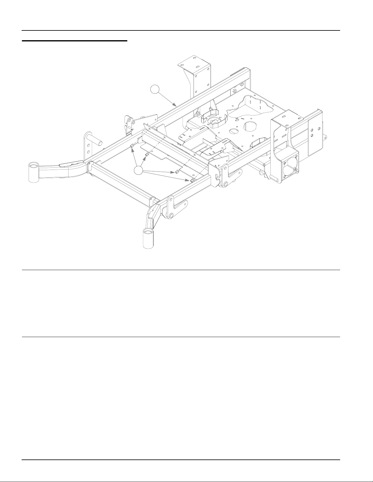
Nutserts Installation
1
2
INDEX
NO.
1 545285 349605 1 TRACTOR FRAME (60")
2 N/A 808493 4 3/8-16 THREAD NUTSERT
SERVICE
PART NO.
545350 347534 1 TRACTOR FRAME (52")
545806 362657 1 TRACTOR FRAME (72”)
MFG.
PART NO.
QTY DESCRIPTION
NOTES:
2-2 350165 5/02
Page 9
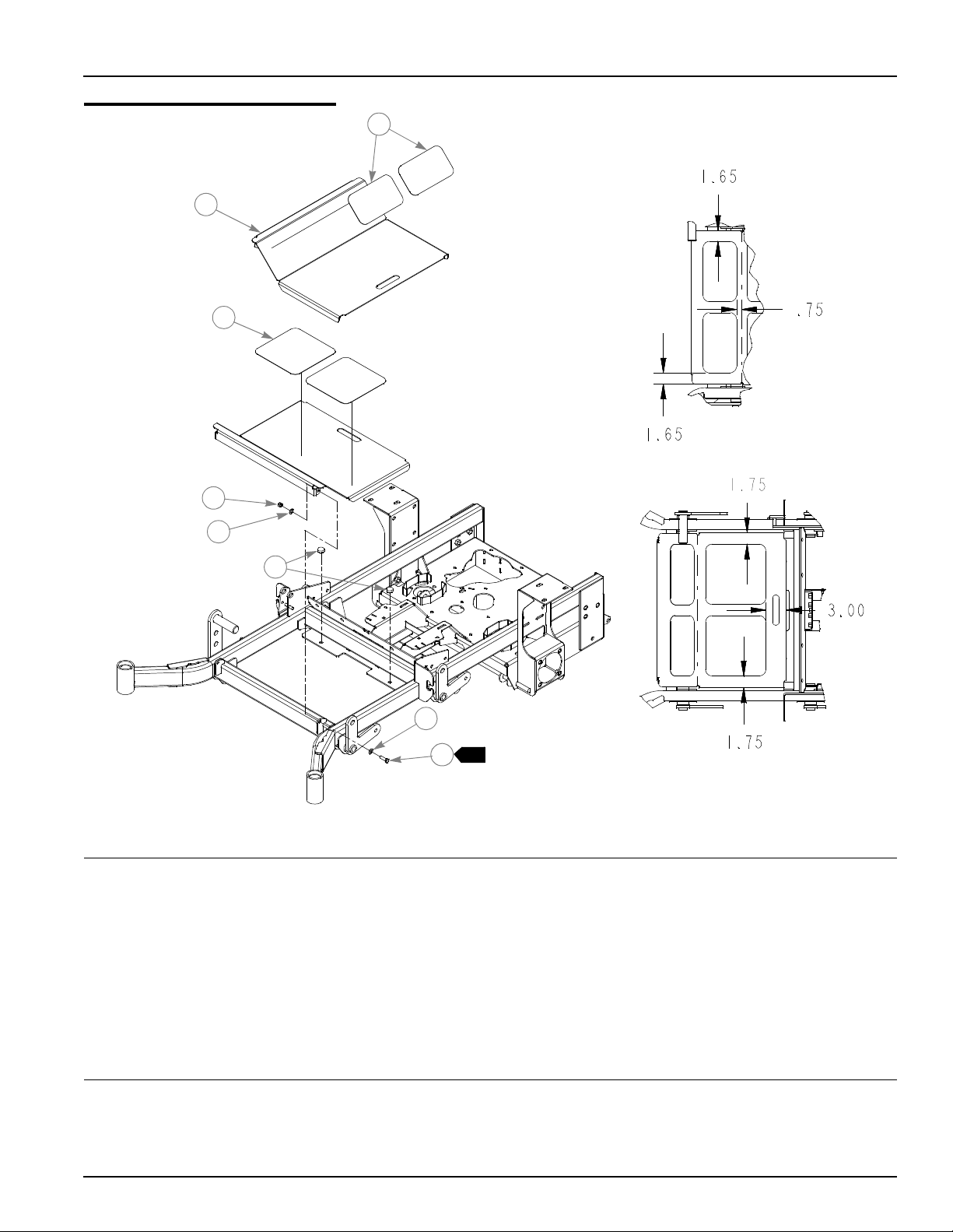
Footrest Assembly
2
3
4
5
1
6
5
1
7
INDEX
NO.
1 359547 359547 2 STEP TREAD
2 348276 348276 1 FLOOR
3 305615 305615 2 PLATFORM STEP TREAD
4 086660 086660 2 NT .375-16 HX LK NY
5 767954 767954 4 FW .406 X .812 X .060 SAE HD ZN
6 781880 781880 2 RUBBER BUMPER
7 052860 052860 2 CS .375-16 X 1.250 HX G5 ZN
SERVICE
PART NO.
MFG.
PART NO.
QTY DESCRIPTION
NOTES:
1. Do not tighten, Item 2 (348276 Floor) must be able to pivot on these
bolts.
350165 5/02 2-3
Page 10

2-4 350165 5/02
Page 11

Chapter 3 Contents
Hydraulic System Installation. . . . . . . . . . . . . . . . . . . . . . . . . . . . . . . 3-2
350165 5/02 3-1
Page 12
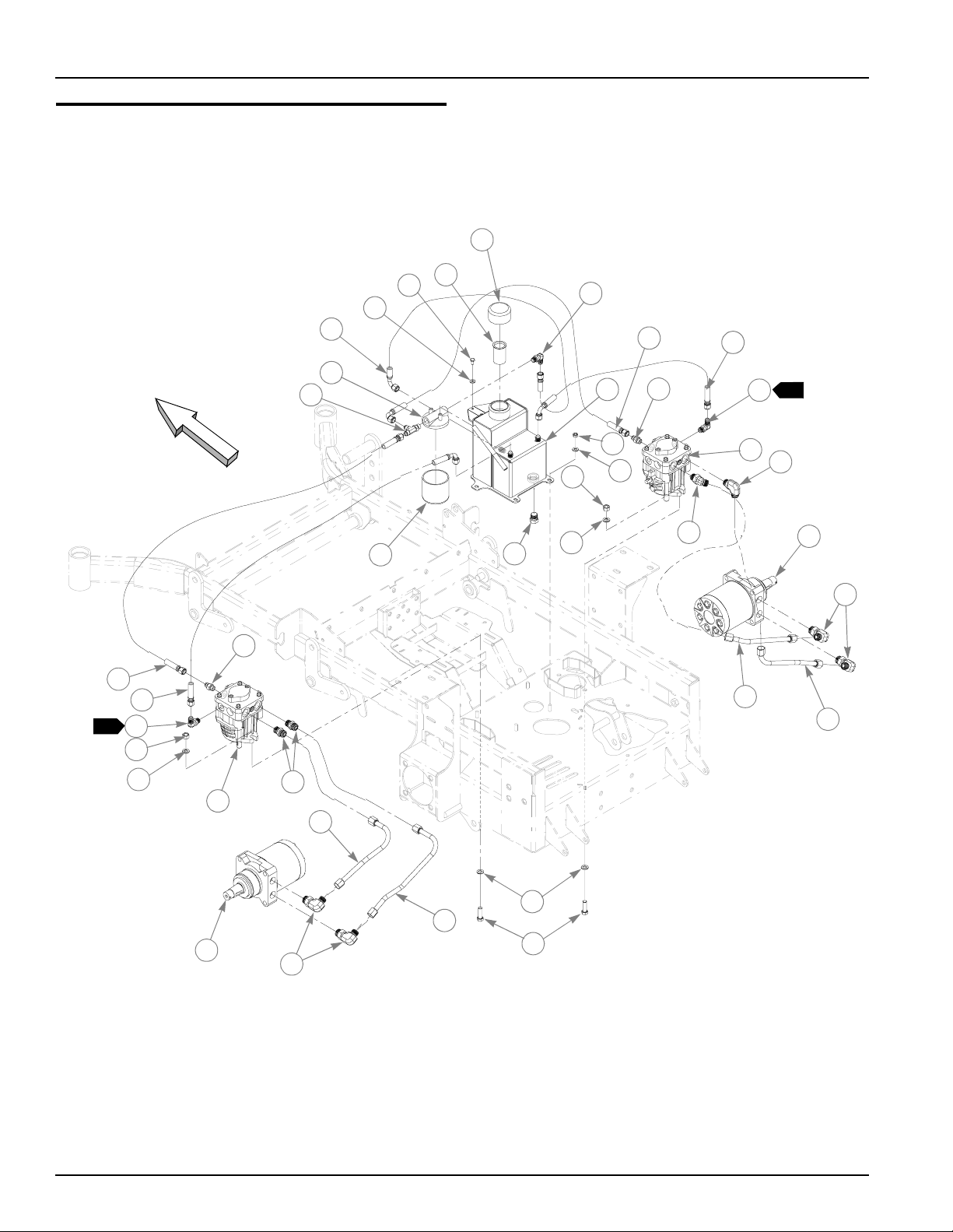
Hydraulic System Installation
2
1
16
15
31
4
3
17
19
5
20
18
17
3
FRONT
30
18
3
17
10
11
6
10
14
20
29
9
28
23
11
7
21
26
8
22
12
24
25
12
11
27
13
24
3-2 350165 5/02
Page 13

Hydraulic System Installation
ITEM
NO.
1 768515 768515 2 FW .281 X .625 X .051/.080 HD ZN/YL
2 055947 055947 2 CS .250-20 X .500 HX G5 ZN
3 032771 032771 1 STRAINER
4 032763 032763 1 BREATHER CAP
5 349860 349860 1 RESERVOIR
6 034272 034272 4 NT .312-18 HX G5 ZN
7 768523 768523 4 FW .343 X .687 X .051/.080 HD ZN/YL
8 781062 781062 1 HYDRO-GEAR PUMP, BDP-10A-300
9 781047 781047 1 HYDRO-GEAR PUMP BDP-10A-400
10 041707 041707 4 NT .437-14 HX G5 ZN
11 704742 704742 8 FW .453 X .812 X .060 ZN
12 781054 781054 2 ROSS/PARKER WHEEL MOTOR, MB-15
13 705186 705186 4 CS .437-14 X 1.375 HX G5 ZN
14 768341 768341 1 FILTER ELEMENT
15 768333 768333 1 FILTER HEAD
16 781575 N/A 1 -6STR -6 90°, PUSHLO C H O SE 4.75"
17 763946 N/A 3 90°, -6 O-RING/-6 JIC FITTING
18 778985 N/A 2 -6STR -6 90°, PUSHLOC HOSE, 13.00"
19 781591 N/A 1 -6STR -6 90°, PUSHLOC HOSE, 15.00"
20 779132 N/A 2 STR-6MORB/-6JIC FITTING
21 781559 N/A 1 45°, -8MORB/-8MSL FITTING
22 781542 N/A 1 90°,-8MORB/-8MSL FITTING
23 781658 N/A 1 STR-8-MORB/HEX PLUG
24 781526 N/A 4 90°, -10MORB/-8MSL FITTING
25 781500 N/A 1 RIGHT LOOP/RP-BM HYDRO TUBE
26 781492 N/A 1 RIGHT LOOP/LP-TM HYDRO TUBE
27 781484 N/A 1 LEFT LOOP/RP-BM HYDRO TUBE
28 781476 N/A 1 LEFT LOOP/LP-TM HYDRO TUBE
29 781534 N/A 2 STR-8MORB/-8MSL FITTING
30 781518 N/A 1 -6STR -6STR PUSHLOC HOSE, 9.00"
31 763953 N/A 1 -6 O-RING/-6JIC/6JIC T FITTING
SERVICE
PART NO.
N/A 781469 1 MMZ HYDRAULIC KIT (INCLUDES 16-31)
MFG.
PART NO.
QTY DESCRIPTION
NOTES:
1. Add 3.5 oz. Lubrizol (027912) to new system or when hydraulic oil is
changed (see Owner’s Manual).
2. Hydraulic system capacity is 5 US quarts. Fill reservoir to within 1" of top
of Item 3 (032771 Strainer)
3. Two of Items 17 (7 63 946 9 0°, - 6 O-Rin g/-6 JIC Fit ting) mu st be instal led
to pumps prior to installing pumps in tractor.
350165 5/02 3-3
Page 14

HYDRAULIC SYSTEM CHARGING PROCEDURE
1. Set handles in the neutral position.
2. Start engine at idle.
3. Let run for a minimu m of 30 seconds.
4. Stroke handles to forward position.
5. If motors do not turn in 15 se conds r eturn handle s to neutr al and
repeat step 3 and 4 (one time).
6. If motors do not turn after second attempt, shut off the engine
and check for oil at the pump.
7. Increase throttle to half speed and work handles through forward
and reverse position until the motor operates smoothly
throughout the entire speed range.
3-4 350165 5/02
Page 15

Chapter 4 Contents
Battery Installation. . . . . . . . . . . . . . . . . . . . . . . . . . . . . . . . . . . . . . . 4-2
Deck Lift Assembly . . . . . . . . . . . . . . . . . . . . . . . . . . . . . . . . . . . . . . 4-4
Steering and Brake Assembly . . . . . . . . . . . . . . . . . . . . . . . . . . . . . . 4-6
Pump Belt and Pulley Installation . . . . . . . . . . . . . . . . . . . . . . . . . . 4-10
Deck Lift Spring 782995 . . . . . . . . . . . . . . . . . . . . . . . . . . . . . . . . . 4-12
Deck Lift Indicator 783001. . . . . . . . . . . . . . . . . . . . . . . . . . . . . . . . 4-13
350165 5/02 4-1
Page 16
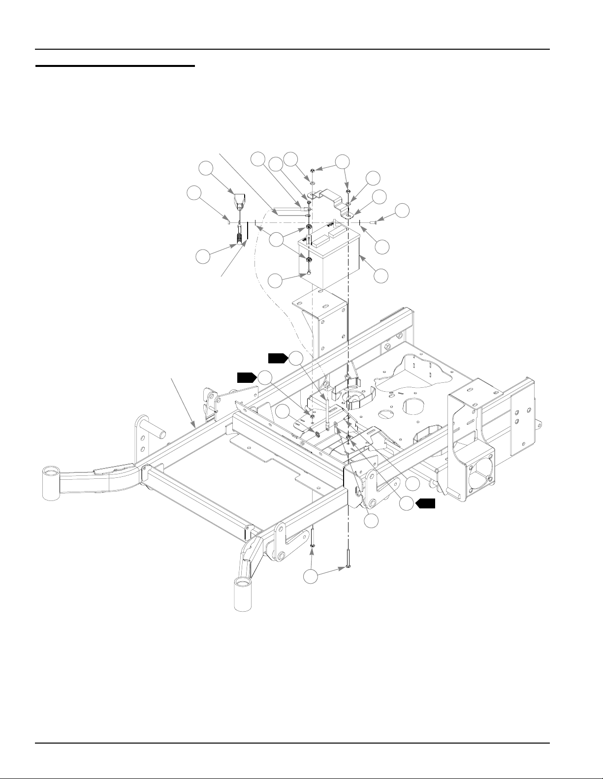
Battery Installation
BLACK WIRE,
PART OF WIRE
HARNESS
2
3
1
5
1
6
5
7
8
RED WIRE,
PART OF WIRE
HARNESS
TRACTOR
FRAME
9
4
8
1
3
2
11
14
9
10
12
2
11
5
13
4-2 350165 5/02
Page 17

Battery Installation
INDEX
NO.
1 024927 024927 2 NT .250-20 HX GR.5 ZN
2 771428 771428 1 RED BA TTERY CABLE BOOT
3 768820 768820 1 BATTERY GROUND CABLE
4 744276 744276 1 POSITIVE BATTERY CABLE
5 768523 768523 3 FW .343 X .687 X .051/.080 HD ZN/YL
6 058776 058776 2 NT .312-18 HX NL ZN
7 348417 348417 1 BATTERY CLAMP STRAP
8 055939 055939 2 CS .250-20 X .750 HX G5 ZN
9 029868 029868 4 LW .250 INT-EXT TOOTH ZN
10 740696 740696 1 BATTERY
11 034272 034272 2 NT .312-18 HX G5 ZN
12 034280 034280 1 CS .312-18 X .750 HX G5 ZN
13 779850 779850 2 CB .312-18 X 3.00 FUL ZN
14 029876 029876 1 LW .312 INT-EXT TOOTH ZN
SERVICE
PART NO.
MFG.
PART NO.
QTY DESCRIPTION
NOTES:
1. Battery ground cable and b lack wire of harness should not be conn ected
to battery until engine is ready to be started. See Owners Manual.
2. Items 12 (034272 NT .312-18 HX G5 ZN) to be tightened against frame
to lock Items 14 (779850 CB .312-18 X 3.00 FUL ZN) to frame.
350165 5/02 4-3
Page 18
Deck Lift Assembly
1
2
4
5
TRACTOR
FRAME
5
6
7
10
4
3
5
12
11
4
5
13
1
5
10
10
4
6
4
1
1
5
1
8
9
10
4
8
4
14
8
4
9
4-4 350165 5/02
9
Page 19

Deck Lift Assembly
ITEM
NO.
1 348318 348318 1 STOP HANDLE
2 348284 348284 1 HEIGHT ADJ STOP
3 783001 783001 1 DECK LIFT INDICATOR SUBASSEMBLY
4 704643 704643 8 NT .437-14 HX FLG ZN
5 781294 781294 7 CLIP E, 1.00 X .625 X .050
6 782995 782995 2 DECK LIFT SPRING SUBASS EM BLY
7 781229 781229 1 CE .750 X 2.25 X 1.75 HEADLESS
8 055749 055749 3 CS .437-14 X 1.750 HX G5 ZN
9 348391 348391 4 DECK LIFT CHAIN
10 015495 015495 4 STRAIGHT GREASE FITTING
11 034272 034272 1 NT .312-18 HX G5 ZN
12 756270 756270 1 CS .312-18 X 1.50 FUL THR GR5 ZN
13 348458 348458 1 DECK LEVELER YOKE
14 781831 781831 1 CS .437-14 X 1.750 FUL THD G5 ZN
SERVICE
PART NO.
MFG.
PART NO.
QTY DESCRIPTION
NOTES:
1. Apply grease to zerks on new assemblies.
350165 5/02 4-5
Page 20
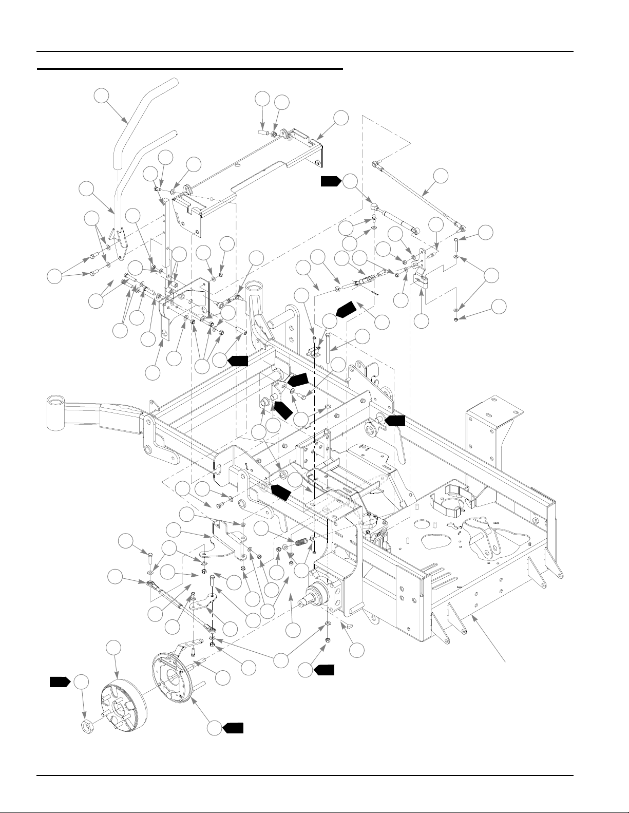
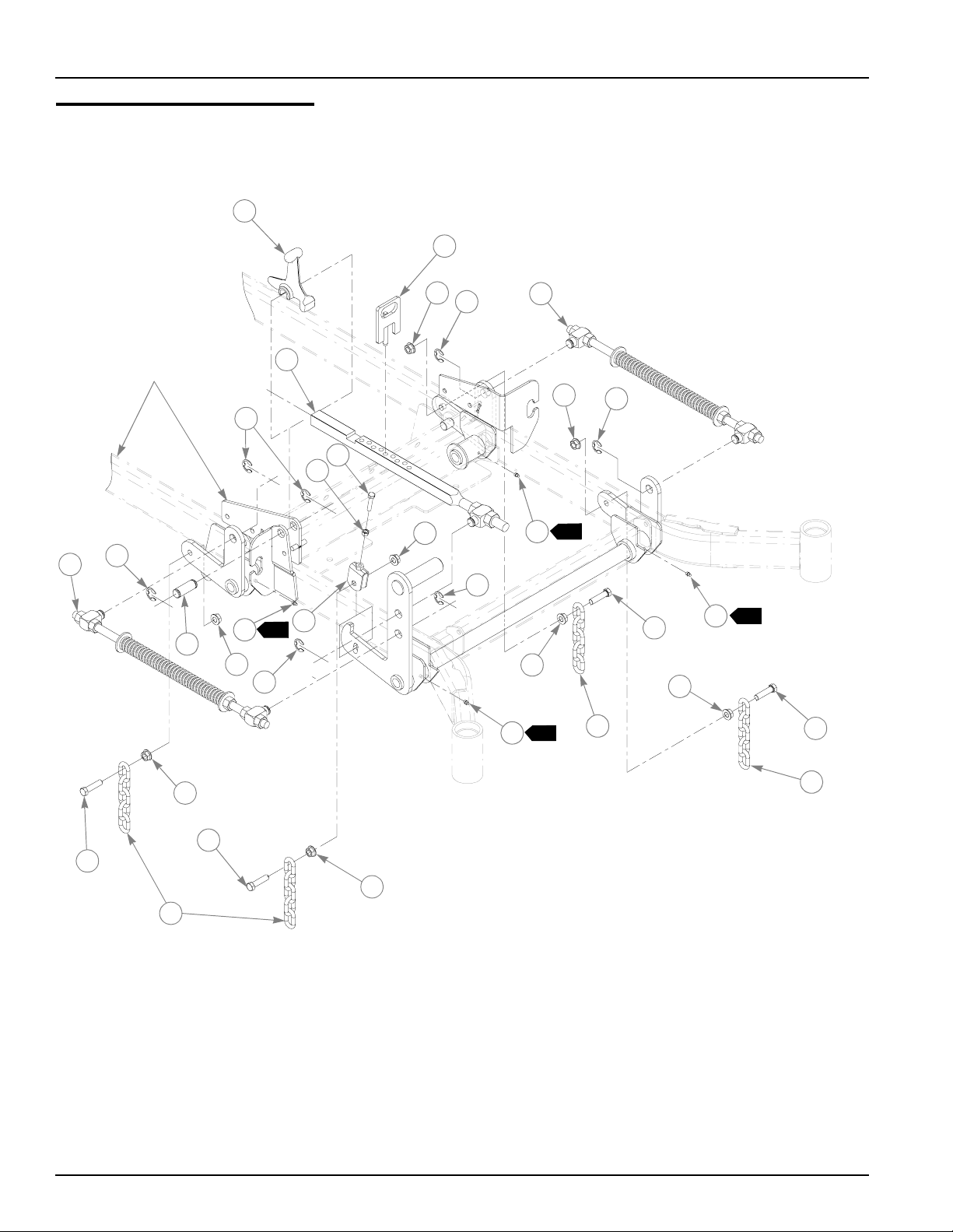
Steering and Park Brake Assembly
1
11
12
13
10
8
2
3
6
7
4
5
5
3
3
9
3
14
3
28
24
22
25
26
27
6
23
24
18
7
33
6
7
16
17
7
6
3
20
3
9
21
7
19
43
15
1047
5
4
3
30
29
3
3
40
10
3
3
39
45
31
38
3
32
31
41
6
42
3
39
32
7
3
33
46
3
4
15
TRACTOR
FRAME
33
7
37
34
1
44
36
35
2
4-6 350165 5/02
Page 21

Steering and Park Brake Assembly
ITEM
NO.
1 781260 781260 2 STEERING BAR GRIP
2 348755 348755 2 STEERING BAR
3 767954 767954 48 FW .406 X .812 X .060 SAE HD ZN
4 036244 036244 10 CS .375-16 X 1.000 HX G5 ZN
5 705178 705178 6 CS .375-16 X 1.750 HX G5 ZN
6 041152 041152 8 NT .312-24 HX ZN
7 768523 768523 18 FW .343X .687 X .051/.080 HD ZN/YL
8 348946 348946 2 STEERING ARM MOUNT
9 348888 348888 1 STEERLEVER SUPPORT LH
10 055822 055822 8 CS .375-16 X .750 HX G5 ZN
11 781716 781716 2 SS .500-13 X 1.75 SH ZN
12 053199 053199 2 NT .500-13 HX JAM ZN
13 348987 348987 1 STEERING CONTROL PANEL
14 348862 348862 4 STEERLEVER BUSHING
15 086660 086660 8 NT .375-16 HX LK NY
16 781583 781583 2 BRAKE ROD ASSEMB LY
17 350413 350413 2 NEUT RAL STOP YOKE ASSEMBY
18 076745 076745 2 CE .375 X 1.125 .15 X .968 ZN
19 760199 760199 2 CP .125D X .750 LG ZN
20 063198 063198 4 CS 10-24 X .750 HXFLK ZN
21 781211 781211 2 PUSH BUTTON SWITCH
22 781286 781286 2 PUMP ROD ADJUSTER ASSEMBLY
23 781088 781088 2 DAMPENER
24 781922 781922 4 DAMPENER BALL STUD
25 704163 704163 2 CS .250-20 X 2.00 HX G5 ZN
26 768515 768515 4 FW .281 X .625 X .051/.080 HD ZN/YL
27 068551 068551 2 NT .250-20 HX NL ZN
28 350454 350454 1 L.S PUMP ARM
29 348797 348797 2 ADJUSTABLE PIVOT
30 781153 781153 4 BUSHING
31 005116 005116 4 CS .375-16 X 1.375 HX G5 ZN
32 054502 054502 4 NT .375-16 HX GRD 5 ZN
33 034272 034272 8 NT .312-18 HX G5 ZN
34 781765 781765 2 BRAKE DRUM-HUB ASSEMBLY
35 781112 781112 1 BRAK E ASS EM BLY
7
8
36 036236 036236 4 CS .312-18 X 1.000 HX G5 ZN
37 350272 350272 2 BRAKE ARM EXTENS ION
38 350264 350264 1 R.S. BRAKE PIVOT ARM
39 765339 765339 4 BUSHING
40 059832 059832 4 NT #10-24 HX NL ZN
41 018861 018861 2 COMPRESSION SPRING
42 718791 718791 2 NT .375-24 NYLOCK ZN
43 782979 782979 2 CS .375-16 X 4.75 HX G5 ZN
44 065516 N/A 2 ROSS CASTLE NUT
45 350397 350397 2 BRAKE LINK TURNBUCKLE
SERVICE
PART NO.
348714 348714 1 STEERLEVER SUPPORT RH
348979 348979 1 R.S PUMP ARM
781351 781351 1 BRAKE ASSEM BLY
350330 350330 1 L.S. BRAKE PIVOT ARM
MFG.
PART NO.
QTY DESCRIPTION
350165 5/02 4-7
Page 22
ITEM
NO.
46 064337 N/A 2 ROSS KEY
47 781716 781716 2 SS .500-13 X 1.75 SH ZN
SERVICE
PART NO.
MFG.
PART NO.
QTY DESCRIPTION
NOTES:
1. Torque to 350-375 ft.-lbs. Included with wheel motor.
2. Torque brake assembly mounting bolts to 100 ft.-lbs.
3. Pin to be clean and free of rust. Apply thin coat of grease prior to
installing Item 30 (781153 Bushing).
4. Do not torque this fastener, should be snug but allow Item 38 (350330
Brake Pivot Arm) to pivot freely.
5. Item 29 (348797 Adjustable Pivot) to be adjusted such that Item 9
(348888/348714 Steerlever Support) has no end play.
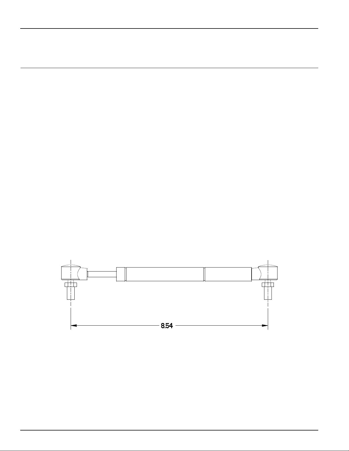
6. See Fig. 1 for initial ins tallation of Item 23 (Dampener)
7. 781112 used on right wheel.
8. 781351 used on left wheel.
9. With Steering Bars in park position, adjust Push Button Switch (Item 21)
outboard until switch is activated by Brake Pivot Arm (Item 38). Repeat
for opposite side.
10. Apply Loctite 609 on threads. Fill hex of set screw with 3M EC-1252
tamper proof sealant after adjustments are complete.
NEUTRAL ADJUSTMENT
Fig. 1
4-8 350165 5/02
Page 23

This page inte ntionally left blank.
350165 5/02 4-9
Page 24
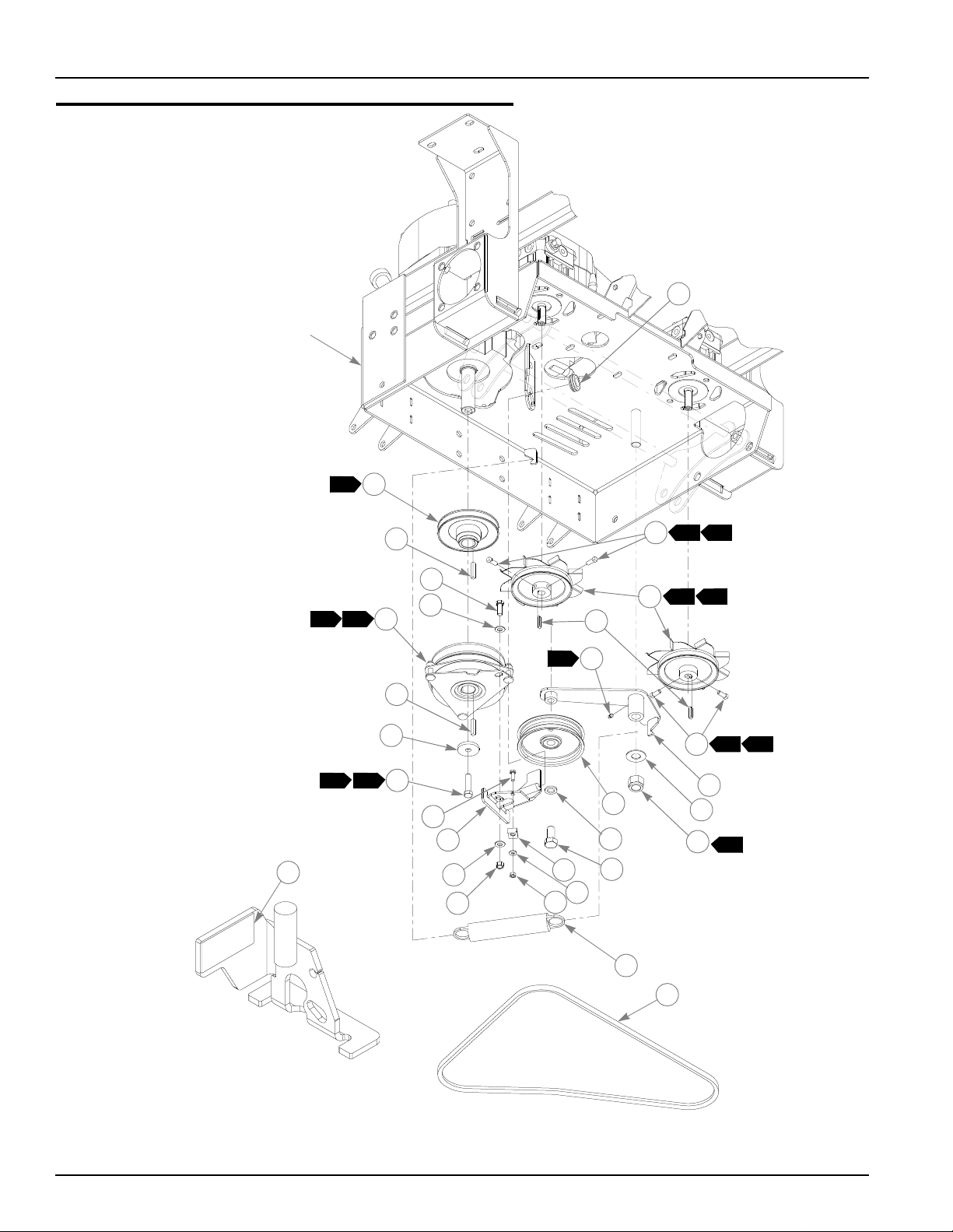
Pump Belt and Pulleys Installation
TRACTOR
FRAME
1
2
3
1
6 4
9
27
4
1
8
6
11
5
15
1
5
10
2
3
7
34
8
16
19
22
17
18
23
20
5
21
24
9
13
14
6 4
12
7
25
26
LOCATION OF
RUBBER BUMPER
4-10 350165 5/02
Page 25

Pump Belt and Pulleys Installation
INDEX
NO.
1 748681 748681 1 GM .75 X 1.35 X 1.06 X .18 GROMMET
2 779876 779876 1 ENGINE SC SINGLE PULLEY
3 212076 212076 2 KEY 1/4 SQ X 1.50 LONG
4 036244 036244 1 CS .375-16 X 1.000 HX G5 ZN
5 767954 767954 2 FW .406 X .812 X .060 SAE HD ZN
6 781039 781039 1 CLUTCH
7 783829 783829 1 FW .460 X 1.750 X .250 ZNYC
8 763391 763391 1 CS .437-20 X 1.750 G5 ZN
9 083196 083196 4 SS .312-18 X .750 SQ-HD ZN
9
10 325308 325308 2 PULLEY & FAN
11 768127 768127 2 KEY 5MM X 30MM RADIUS ENDS
12 349761 349761 1 PUMP IDLER ARM
13 025296 025296 1 FW .760 X 1.625 X .08 ZN
14 061101 061101 1 NT .750-10 HX NL ZN
15 015495 015495 1 STRAIGHT GREASE FITTING
16 781856 781856 1 IDLER PULLEY
17 028118 028118 1 FW .62 X 1.00 X.134 ZN
18 781872 781872 1 CS .625-11 X 1.25 HX G5 ZN
19 055939 055939 1 CS .250-20 X .750 HX G5 ZN
20 362392 362392 1 CLUTCH ANCHOR BRACKET
21 054502 054502 1 NT .375-16 HX GRD 5 ZN
22 778738 778738 1 .312 WIRING CLAMP
23 768515 768515 1 FW .281 X .625 X .051/.080 HD ZN/YL
24 024927 024927 1 NT .250-20 HX GR.5 ZN
25 781302 781302 1 IDLER SPRING
26 781443 781443 1 A-SEC PUMP IDLER BELT
27 781918 781918 1 RUBBER BUMPER
SERVICE
PART NO.
030601 N/A 4 SS .312-18 X .500 SH NL
MFG.
PART NO.
QTY DESCRIPTION
NOTES:
1. Coat ID with anti seize.
2. Set blade tips .12"±.03" from surface of engine plate.
3. Torque to 45-48 ft-lbs.
4. Use Loctite 242 on threads.
5. Apply grease at zerk.
6. Torque to 12-15 ft-lbs.
7. Do not torque Item 14 (NT .750-10 HX NL ZN), Item 12 (349761 Pump
Idler Arm) should pivot freely.
8. Electric clutch burnishing procedure: After installing a new clutch it is
important to burnish the clutch to insure maximum deck clutch lif e . In an
open area with n o bystand ers set the engine spee d to half thr ottle. C ycle
the deck clutch on for 15 seconds, and then off for 15 seconds. Repeat
this operation 10 times, it will require about 5 minutes to complete.
9. On tractors with serial numbers prior to 01082125.
350165 5/02 4-11
Page 26

Deck Lift Spring 782995
1
3
5
2
4
3
1
2
1
INDEX
NO.
1 016972 N/A 5 NT .625-11 HX G5 ZNYC
2 781187 N/A 2 DECK LIFT BLOCK
3 017152 N/A 2 FW .680 X 1.750 X .14 SAE ZNYC
4 781401 N/A DECK LIFT SPRING
5 781138 N/A 1 DECK LIFT THREADED ROD
SERVICE
PART N O.
MFG.
PART N O.
QTY DESCRIPTION
NOTES:
4-12 350165 5/02
Page 27
Deck Lift Indicator 783001
1
2
3
2
INDEX
NO.
1 781203 N/A 1 DECK LIFT HEIGHT INDICATOR
2 008417 N/A 2 N .750-10 HX G ZNYC
3 781930 N/A 1 DECK LIFT 3/4" BLOCK
SERVICE
PART NO.
MFG.
PART NO.
QTY DESCRIPTION
NOTES:
350165 5/02 4-13
Page 28

4-14 350165 5/02
Page 29

Chapter 5 Contents
Kawasaki Engine Installation. . . . . . . . . . . . . . . . . . . . . . . . . . . . . . . 5-2
Fuel System Installation. . . . . . . . . . . . . . . . . . . . . . . . . . . . . . . . . . . 5-4
Instrument Panel Assembly/Installation. . . . . . . . . . . . . . . . . . . . . . . 5-6
Electrical Schematic . . . . . . . . . . . . . . . . . . . . . . . . . . . . . . . . . . . . . 5 -8
350165 5/02 5-1
Page 30

Kawasaki Engine Installation
RED/BLK
6
TRACTOR
FRAME
2
3
6
2
8
PURPLE
POSITIVE
BATTERY
CABLE
5
6
7
12
13
1
2
6
2
4
10
11
TO ENGINE
15
SENSOR
YELLOW
14
16
17
P/O ENGINE
2
TAN/RED
TO BULLET
TERMINALS
TO SPADE
TERMINAL
9
2
BLK
2
2
21
20
1
29
23
27
28
18
19
HOUR METER
CONNECTION
24
25
22
11
26
5-2 350165 5/02
Page 31

Kawasaki Engine Installation
ITEM
NO.
1 777656 777656 1 KAWASAKI 23 HP ENGINE (FH680V, 3600 RPM)
5
6
2 024927 024927 3 NT .250-20 HX GR.5 ZN
3 044255 044255 1 NT #10-32 HX ZN
4 768820 768820 1 BATTERY CABLE
5 771428 771428 1 RED BATTERY CABLE BOOT
6 768515 768515 5 FW .281 X .625 X .051/.080 HD ZN/YL
7 055947 055947 2 CS .250-20 X .500 HX G5 ZN
8 030817 030817 1 STARTER SOLENOID
9 781450 781450 1 TRACTOR WIRE HARNESS
10 034272 034272 4 NT .312-18 HX G5 ZN
11 768523 768523 6 FW .343 X .687 X .051/.080 HD ZN/YL
12 781732 781732 1 MUFFLER MANIFOLD
13 781724 781724 1 MUFFLER
14 780783 780783 1 KAWASAKI OIL DRAIN EXTENSION
15 780775 780775 1 OIL DRAIN ADPT O-RING
16 780841 780841 2 KAW (23) MUFFLER GASKET
17 360693 360693 1 HEAT SHIELD
18 017004 017004 4 LW .312 MED SPRING ZN
19 782664 782664 4 NT M8-1.25 HX STAINLESS STEEL
20 782649 782649 1 KAW (23) EXHAUST PIPE CLAMP
21 720177 720177 2 CS M 8-1.25 X 20 10.9 HXFL ZN
22 029876 029876 4 LW .312 INT-EXT TOOTH ZN
23 052837 052837 4 CS .312-18 X 1.500 HX G5 ZN
24 350371 350371 1 MUFFLER GUARD
25 349704 349704 1 ENGINE CAGE MOUNT PLATE
26 064006 064006 2 CS .312-18 X .625 HX G5 ZN
27 767962 767962 6 FW .531 X 1.063 X .090 SAE HD ZN
28 016527 016527 6 CS .500-13 X 1.00 HX G5 ZN
29 769166 769166 1 HOUR METER
SERVICE
PART NO .
782318 782318 1 KAWASAKI 25 HP ENGINE (FH721V, 3600 RMP)
MFG.
PART NO.
QTY DESCRIPTION
NOTES:
1. Includes mounting hardware.
2. Part of Item 9 (781450 Tractor Wire Harness).
3. Engine oil capacity; 2 US quarts.
4. Engine RP M to be set at 3600± 50.
5. 23 HP engine used in 926253, 926295, 926311, and 926345 only.
6. 25 HP engine used in 926345, 926469, 926550, and 926568 only.
350165 5/02 5-3
Page 32

Fuel System Installation
6
5
1
2
4
5
6
7
5
15
12
11
10
13
15
18
15
5
6
8
1
14
15
3
11
10
17
16
9
16
17
5
6
TRACTOR FRAME
WITH ENGINE
5-4 350165 5/02
Page 33

Fuel System Installation
ITEM
NO.
1 784181 784181 2 FUEL TANK CAP
2 781179 781179 1 LEFT SIDE FUEL TANK
3 781161 781161 1 RIGHT SIDE FUEL TANK
4 349944 349944 1 REAR SEAT SUPPORT
5 767954 767954 14 FW .406 X .812 X .060 SAE HD ZN
6 055822 055822 12 CS .375-16 X .750 HX G5 ZN
1
7 000398 000398 1 CLAMP
8 036244 036244 2 CS .375-16 X 1.000 HX G5 ZN
9 045088 045088 1 HOSE CLAMP 1"
10 783944 N/A 2 FUEL SHUT-OFF VALVE
2
11 784348 N/A 2 GROMMET,FUEL SHUT-OFF VALVE
2
12 015818 015818 1 FUEL LINE 35” TOTAL
13 015818 015818 1 FUEL LINE 6” TOTAL
14 015818 015818 1 FUEL LINE 12” TOTAL
15 000323 000323 6 CLIP
16 016527 016527 8 CS .500-13 X 1.00 HX G5 ZN
17 767962 767962 8 FW .531 X 1.063 X .090 SAE HD ZN
18 781633 781633 1 ‘T’ FITTING, -6BARB/-6BARB/-6BARB
SERVICE
PART NO.
000331 000331 3 BLACK CABLE TIE (NOT SHOWN)
MFG.
PART NO.
QTY DESCRIPTION
1. Torque to 20 ft.-lbs
2. Supplied with new fuel tank.
NOTES:
350165 5/02 5-5
Page 34

Instrument Panel Assembly/Installation
1
2
4
1
5
1
6
3
10
8
14
7
9
3
14
8
7
1
7
4
11
12
13
FUSE SIZE
AND LOCATION
10a
FUSE SIZE
AND LOCATION
5a
20a
RIGHT SIDE
FUEL TANK
12
11
5-6 350165 5/02
Page 35

Instrument Panel Assembly/Installation
ITEM
NO.
1 776476 776476 1 PTO SWITCH
2 083022 N/A 1 IGNITION KEY
3
3 045898 045898 1 KEY SWITCH
4 059832 059832 6 NT #10-24 HX NL ZN
5 026237 N/A 3 RELAY
6 762195 N/A 1 DELAY MODULE
7 704932 704932 6 FW .219 X .500 X .048 ZN
8 714998 714998 3 MS #10-24 X .625 HX ZN
9 778365 778365 1 THROTTLE/CHOKE CABLE
10 712257 712257 1 RED INDICATOR LIGHT
11 055947 055947 3 CS .250-20 X .500 HX G5 ZN
12 768515 768515 3 FW .281 X .625 X .051 /.080 HD ZN/YL
13 349308 349308 1 INSTRUMENT PANEL
14 785030 785030 1 Z CHOKE CABLE
SERVICE
PART NO.
2 785808 785808 1 INDAK COATED KEY
MFG.
PART NO.
QTY DESCRIPTION
NOTES:
1. Part of 781450 (Tractor Wire Harness)
2
2. Used on units with serial number above 01102176.
350165 5/02 5-7
Page 36

Electrical Schematic
5-8 350165 5/02
Page 37

Electrical Schematic
350165 5/02 5-9
Page 38

5-10 350165 5/02
Page 39

Chapter 6 Contents
Front Wheel Assembly. . . . . . . . . . . . . . . . . . . . . . . . . . . . . . . . . . . . 6-2
Front Wheel Breakdown . . . . . . . . . . . . . . . . . . . . . . . . . . . . . . . . . . 6-4
Drive Wheel Assembly. . . . . . . . . . . . . . . . . . . . . . . . . . . . . . . . . . . . 6-5
Anti-Rollover Wheel Assembly. . . . . . . . . . . . . . . . . . . . . . . . . . . . . . 6-6
350165 5/02 6-1
Page 40

Front Wheel Assembly
1
2
3
3
4
5
3
4
6
7
8
9
9
2
10
5
3
4
6
TRACTOR
FRAME
1
2
3
3
4
11
7
9
9
1
11
1
8
6-2 350165 5/02
Page 41

Front Wheel Assembl y
INDEX
NO.
1 705954 705954 2 CS .500-13 X 1.25 HX G5 ZN
2 344267 344267 2 FW .510 X 2.15 X .187 SPL ZN
3 712976 712976 2 FW .531 X 1.375 X .125 ZNYC
4 784223 784223 4 BEARING W/O COLLAR
5 387035 387035 2 SPACER, 1.07 X 1.312 X 2.793
6 045765 045765 2 FW 1.030 X 1.500 X.134 ZN
7 349266 349266 2 FORK
8 041475 041475 2 CS .750-10 X 9.50 HX ZN
9 025296 025296 4 FW .760 X 1.625 X .08 ZN
10 061101 061101 2 NT .750-10 HX NL ZN
11 747782 747782 2 WHEEL & TIRE ASSY
SERVICE
PART NO.
MFG.
PART NO.
QTY DESCRIPTION
NOTES:
1. Apply grease to zerks.
2. Torque to 100 ft.-lbs.
3. Assemble with extended inner race towa rd i tem 5 ( 38 703 5 Spacer, 1.07
x 1.312 x 2.793).
350165 5/02 6-3
Page 42

Front Wheel Breakdown - 747782
1
1
2
3
4
1
ITEM
NO.
1 039677 N/A 2 WHEEL BEARING
2 747741 N/A 1 13 X 6.50 TIRE
3 747832 N/A 1 6 X 4.5 WHEEL
4 782771 N/A 1 BEARING SPACER
5 019521 N/A 1 TIRE VALVE
SERVICE
PART NO.
1. Inflate tire to 8-10 psi.
MFG.
PART NO.
5
QTY DESCRIPTION
NOTES:
6-4 350165 5/02
Page 43

Drive Wheel Assembly Installation
1
6
2
2
MFG.
3
QTY DESCRIPTION
1
5
INDEX
NO.
4
SERVICE
PART NO.
1 784058 784058 2 WHEEL & TIRE ASSY FOR 72" (QTY PER TRACTOR)
2 781245 N/A TIRE, 12 X 12 X 24 FOR 72”
3 784066 N/A WHEEL ASSY 12 X 8.50 FOR 72”
4 019521 N/A TIRE VALVE
5 061077 061077 5 WHEEL NUT (QTY PER WHEEL)
1 781237 781237 2 WHEEL & TIRE ASSY FOR 60"(QTY PER TRACTOR)
2 781245 N/A TIRE, 12 X 12 X 24 FOR 60"
3 781252 N/A 2 WHEEL ASSEMBLY 12 X 8.50 FOR 60”
4 019521 N/A 2 TIRE VALVE
5 061077 061077 5 WHEEL NUT (QTY PER WHEEL)
1 782078 782078 2 WHEEL & TIRE ASSY FOR 52"
2 782284 N/A TIRE, 23 X 9.50-12 FOR 52”
3 782086 N/A WHEEL ASSY 12 X 7.00 FOR 52”
4 019521 N/A 2 TIRE VALVE
5 061077 061077 5 WHEEL NUT (QTY PER WHEEL)
6 770859 N/A 10 1/2" WHEEL LUG STUD
PART NO.
NOTES:
1. Torque to 65-75 ft. lbs.
2. Inflate tire to 8-10 psi.
350165 5/02 6-5
Page 44

Anti-Rollover Wheel Assembly
TRACTOR
FRAME
1
1
3
3
1
4
3
2
3
INDEX
NO.
1 068239 068239 2 CS .500-13 X 4.500 HX G5 ZN
2 031997 031997 2 ANTI-SCALP WHEEL
3 767962 767962 4 FW .531 X 1.063 X .090 SAE HD ZN
4 781567 781567 2 NT .50-13 HX LK NY
SERVICE
PART NO.
MFG.
PART NO.
QTY DESCRIPTION
NOTES:
1. Do not torque, wheel must turn freely.
2
6-6 350165 5/02
Page 45

Chapter 7 Contents
72" Deck Assembly . . . . . . . . . . . . . . . . . . . . . . . . . . . . . . . . . . . . . . 7-2
72" Deck Pulley Assembly. . . . . . . . . . . . . . . . . . . . . . . . . . . . . . . . . 7-4
60" Deck Assembly . . . . . . . . . . . . . . . . . . . . . . . . . . . . . . . . . . . . . . 7-6
60" Deck (with Blade Saddles) Pulley Assembly . . . . . . . . . . . . . . . 7-8
60" Deck (No Blade Saddles) Pulley Assembly. . . . . . . . . . . . . . . . 7-10
52" Deck Assembly . . . . . . . . . . . . . . . . . . . . . . . . . . . . . . . . . . . . . 7-12
52" Deck Pulley Assembly. . . . . . . . . . . . . . . . . . . . . . . . . . . . . . . . 7-14
Spindle Housing Assembly - 520627. . . . . . . . . . . . . . . . . . . . . . . . 7-16
Spindle Assembly - 350595. . . . . . . . . . . . . . . . . . . . . . . . . . . . . . . 7-17
350165 5/02 7-1
Page 46

72" Deck Assembly
3
11
14
8
11
8
10
15
6
12
1
2
4
5
2
3
5
4
11
14
3
4
11
8
7
10
12
1
13
1
16
4
4
9
13
12
1
10
11
16
8
11
3
14
11
4
12
8
1
10
11
3
14
11
18
5
4
12
5
1
10
11
3
14
11
8
5
4
5
3
14
17
7-2 350165 5/02
Page 47

72" Deck Assembly
INDEX
NO.
1 545764 348052 1 72" DECK CRATED
2 349324 349354 1 DISCHARGE CHUTE
3 052860 052860 2 CS .375-19 X 1.250 HX G5 ZN
4 767954 767954 18 FW .406 X .812 .060 SAE HD ZN
5 054502 054502 8 NT .375-16 HX G5 ZN
6 349522 349522 1 DISCHARGE CHUTE MOUNT BRACKET
7 086660 086660 2 NT .375-16 HX LK NY
8 781708 781708 6 CS .500-13 X 4.25 HX G5 ZN
9 349803 349803 1 PUSHER
10 053199 053199 6 NT .500-13 HX JAM ZN
11 767962 767962 12 FW .531 X 1.063 X .090 SAE HD ZN
12 781567 781567 6 NT .50-13 HX LK NY
13 015495 015495 2 STRAIGHT GREASE FITTING
14 031997 031997 6 ANTI-SCALP WHEEL
15 781880 781880 1 BUMPER
16 036244 036244 7 CS .375-16 X 1.000 HX G5 ZN
17 318626 318626 1 BAFFLE
5
18 011320 011320 1 CB .375-16 X .750 STD ZN
5
SERVICE
PART NO.
MFG.
PART NO.
QTY DESCRIPTION
NOTES:
1. Secure Item 10 (053199 Nt. .500-13 Hx Jam Zn) to bolt with a drop of
Loctite (271 Red). Tighten Item 10 to shank of Item 8 (781708 Cs .50013 x 4.25 Hx G5 Zn). Anti-scalp wheel must turn freely.
2. Do not torque, Item 2 (349324 Discharge Chute) must pivot freely.
3. Factory assembled in top hole for shipping purposes.
4. Item 9 (349803 Pusher) installed as shown with zerks pointing upward,
apply grease to zerks (see owners manual).
5. Used on mowers with serial number prior to 02012156.
350165 5/02 7-3
Page 48

72" Deck Pulley Assembly
10
6
APPROXIMATE
LOCATION
OF BUMPERS
16
11
15
1
2
4
7
1
9
8
3
5
6
12
13
3
14
18
BELT GUIDE
POSITIONING
18
18
3
30
17
2
28
28
4
19
20
21
22
23
21
24
25
3
18
4 5
26
27
2
29
7-4 350165 5/02
Page 49

72" Deck Pulley Assembly
ITEM
NO.
1 784207 784207 1 B-SECTION BELT
2 016972 016972 2 NT .625-11 HX G5 ZNYC
3 028118 028118 3 FW .62 X 1.00X.134 ZN
4 781385 781385 2 6.00" IDLER PULLEY ,
5 008573 008573 1 CS .500-13 X 2.500 HX G5 ZN
6 070037 070037 1 FW .530 X 1.06 X .19 HRD ZN
7 350561 350561 1 DECK IDLER BUSHING
8 015495 015495 1 STRAIGHT GREASE FITTING
9 349498 349498 1 IDLER ARM
10 781302 781302 1 IDLER SPRING
11 373191 373191 1 SIDE MOUNT CHAIN
12 781872 781872 1 CS .625-11 X 1.25 HX G5 ZN
13 347443 347443 1 TOP IDLER DECK BELT GUIDE
14 781856 781856 1 5.00" IDLER PULLEY
15 781617 781617 2 RUBBER BUMPER
16 348375 348375 1 R.S. PULLEY COVER
17 348524 348524 1 L.S. PULLEY COVER
18 075291 075291 4 CLAMP KNOB
19 784199 784199 3 CS .312-18 X 1.250 FLT SH ZNYC
20 783878 783878 1 IDLER CLAMP
21 016527 016527 15 CS .500-13 X 1.00 HX G5 ZN
22 078386 078386 3 FW .510 X 1.750 X .18 ZN
23 538850 538850 3 DRIVE PULLEY
24 767962 767962 12 FW .531 X 1.063 X .090 SAE HD ZN
25 350595 350595 3 SPINDLE HOUSING ASSEMBLY
26 212472 212472 3 KEY 1/4 SQ X 1.00 LONG
27 783977 783977 3 24" OFFSET FLAT BLADE
28 782474 782474 5 CW .631 2.250 X .187 PNT
29 781872 781872 3 CS .625-11 X 1.25 HX G5 ZNYC
30 783738 783738 2 CS .625-11 X 3.00 FULL HX G5 ZN
SERVICE
PART NO.
779660 N/A 3 OPTIONAL 24" GATOR BLADE CW
MFG.
PART NO.
QTY DESCRIPTION
NOTES:
1. Apply grease to zerk (see owners manual).
2. Torque to 118 ft. lbs.
3. Apply an tisieze to pulley bore.
4. Assemble spindles with grease zerk oriented forward.
5. See “Spindle Assembly - 350595” on page 7-17 for breakdown.
6. See “Deck Belt Routing and Tensioning” on page 8-4 for belt tensioning.
350165 5/02 7-5
Page 50

60" Deck Assembly
3
11
14
8
2
2
3
4
5
4
11
6
3
14
11
10
1
4
9
13
5
4
7
4
2
8
12
17
8
1
18
4
13
11
1
10
1
10
12
18
11
14
3
11
11
3
14
10
11
1
12
10
11
3
14
8
5
11
4
12
12
1
10
8
11
3
14
11
5
4
6
16
4
5
15
7-6 350165 5/02
Page 51

60" Deck Assembly
INDEX NO.
1 545277 349100 1 60" DECK CRATED
2 349324 349324 1 DISCHA RGE CHUTE
3 052860 052860 2 CS .375-16 X 1.250 HX G5 ZN
4 767954 767954 18 FW .406 X .812 X .060 SAE HD ZN
5 054502 054502 8 N T .375-16 HX GRD 5 ZN
6 349522 349522 1 DISCHA RGE CHUTE MOUNT BRACKET
7 086660 086660 2 NT .375-16 HX LK NY
8 781708 781708 6 CS .500-13 X 4.25 HX G5 ZN
9 349803 349803 1 PUSHER
10 053199 053199 6 N T .500-13 HX JAM ZN
11 767962 767962 12 FW .531 X 1.063 X .090 SAE HD ZN
12 781567 781567 6 N T .50-13 HX LK NY
13 015495 015495 2 STRAIGHT GREASE FITTING
14 031997 031997 6 ANTI-SCALP WHEEL
6
6
17 781880 781880 1 BUMP ER
18 036244 036244 7 CS .375-16X1.000 HX G5 ZN
SERVICE
PART N O.
15 318626 318626 1 BAFFLE
16 011320 011320 1 CB .375-16 X .750 STD ZN
MFG.
PART N O.
QTY. DESCRIPTION
5
NOTES:
1. Secure Item 10 (Nt .500-13 Hx Jam Zn) to bolt with a drop of loctite (271
Red). Tighten Item 10 to shank of Item 8 (781708 Cs .500-13 x 4.25 Hx
G5 Zn). Anti-scalp wheel must turn freely.
2. Do not torque, Item 2 (349324 Discharge Chute) must pivot freely.
3. Factory assembled in top hole for shipping purposes.
4. Item 9 (349803 Pusher) installed as shown with zerks pointing upward.
5. Part numbers 784199 (CS .312-18 X 1.250 FLT SH ZNYC) and 783878
(Idler Clamp) must also be ordered when ordering this part for mowers
with serial number 01082000 and higher (see “60" Deck (No Blade
Saddles) Pulley Assembly” on page 7-10).
6. Used on mowers with serial number prior to 02012156.
350165 5/02 7-7
Page 52

60" Deck (with Blade Saddles) Pulley Assembly
APPROXIMATE
LOCATION
OF BUMPERS
1
2
5
6
17
20
60" DECK
18
32
16
7
7
20
13
14
7
6
9
1
10
7
8
3
4
5
12
15
11
2
21
2
4
6
19
22
3
23
30
31
20
BELT GUIDE
POSITIONING
20
25
4
33
24
5
34
26
27
28
2
29
7-8 350165 5/02
Page 53

60" Deck (with Blade Saddles) Pulley Assembly
INDEX
NO.
1 781310 781310 1 B-SECTION BELT
2 016972 016972 2 NT .625-11 HX G5 ZNYC
3 781872 781872 1 CS .625-11 X 1.25 HX G5 ZN
4 347443 347443 1 TOP IDLER DECK BELT GUIDE
5 028118 028118 3 FW .62 X 1.00X.134 ZN
6 781385 781385 2 6.00" IDLER PULLEY ,
7 008573 008573 1 CS .500-13 X 2.500 HX G5 ZN
8 070037 070037 1 FW .530 X 1.06 X .19 HRD ZN
9 350561 350561 1 DECK IDLER BUSHING
10 015495 015495 1 STRAIGHT GREASE FITTING
11 349498 349498 1 IDLER ARM
12 781856 781856 1 5.00" IDLER PULLEY
13 728550 728550 1 SB .50 X .75 SH .375-16 TD ZN
14 728568 728568 1 CW .560 X 1.34 X .05 ZN
15 781682 781682 2 FW .650 X 2.000 X .187 UHMW
16 781302 781302 1 IDLER SPRING
17 373191 373191 1 SIDE MOUNT CHAIN
18 349381 349381 1 R.S. PULLEY COVER
19 349399 349399 1 L.S. PULLEY COVER
20 075291 075291 4 CLAMP KNOB
21 078378 078378 3 CS .500-20 X 1.500 HX G5 ZN
22 078386 078386 3 FW .510 X 1.750 X .18 ZN
23 781328 781328 3 B-SECTION 6.10 E.O.D PULLEY
24 520627 426296 3 SPINDLE HOUSING ASSEMBLY
5
25 212472 212472 6 KEY 1/4 SQ X 1.00 LONG
26 504365 035808 3 BLADE SADDLE
27 777391 777391 3 21" HIGH SAIL CW BLADE
28 752386 752386 3 CW .515 X 2.25 X .204 ZN
29 753798 753798 3 CS .500-20 X 1.75 HX G5 ZN
30 016527 016527 12 CS .500-13 X 1.00 HX G5 ZN
31 767962 767962 12 FW .531 X 1.063 X .090 SAE HD ZN
32 781617 781617 2 RUBBER BUMPER
33 782474 782474 2 CW .631 X 2.250 X .187 PNT
34 783738 783738 2 CS .625-11 X 3.00 FULL HX G5 ZN
SERVICE
PART NO.
779652 N/A 3 OPTIONAL 21" GATOR CW BLADE
MFG.
PART NO.
QTY. DESCRIPTION
NOTES:
1. Apply grease to zerk.
2. Torque to 65-75 ft. lbs.
3. Apply an tisieze to pulley bore.
4. Assemble spindles with grease zerk oriented forward.
5. See “Spindle Housing Ass em bly - 520627” on pa ge 7-16 for breakdown.
6. See “Deck Belt Routing an d Tensioning ” on pag e 8-4 for belt tensio ning.
7. These part used on deck with serial number prior to 01082000. See “60"
Deck (No Blade Saddles) Pulley Assembly” on page 7-10 for later
decks.
350165 5/02 7-9
Page 54

60" Deck (No Blade Saddles) Pulley Assembly
1
2
6
19
60" DECK
16
17
28
15
13
19
5
6
1
12
7
2
5
6
8
10
7
7
9
11
3
18
14
4
5
20
26
26
27
21
2
3
19
BELT GUIDE
POSITIONING
19
25
29
4
22
23
24
25
2
3
7-10 350165 5/02
5
APPROXIMATE
LOCATION
OF BUMPERS
Page 55

60" Deck (No Blade Saddles) Pulley Assembly
INDEX
NO.
1 781310 781310 1 B-SECTION BELT
2 016972 016972 2 NT .625-11 HX G5 ZNYC
3 781872 781872 4 CS .625-11 X 1.25 HX G5 ZN
4 347443 347443 1 TOP IDLER DECK BELT GUIDE
5 028118 028118 3 FW .62 X 1.00X.134 ZN
6 781385 781385 2 6.00" IDLER PULLEY ,
7 008573 008573 1 CS .500-13 X 2.500 HX G5 ZN
8 784199 784199 3 CS .312-18X1.250 FLT SH ZNYC
9 783878 783878 1 IDLER CLAMP
10 070037 070037 1 FW .530 X 1.06 X .19 HRD ZN
11 350561 350561 1 DECK IDLER BUSHING
12 015495 015495 1 STRAIGHT GREASE FITTING
13 349498 349498 1 IDLER ARM
14 781856 781856 1 5.00" IDLER PULLEY
15 781302 781302 1 IDLER SPRING
16 373191 373191 1 SIDE MOUNT CHAIN
17 349381 349381 1 R.S. PULLEY COVER
18 349399 349399 1 L.S. PULLEY COVER
19 075291 075291 4 CLAMP KNOB
20 078386 078386 3 FW .510 X 1.750 X .18 ZN
21 781328 781328 3 B-SECTION 6.10 E.O.D PULLEY
22 350595 350595 3 SPINDLE HOUSING ASSEMBLY
23 212472 212472 3 KEY 1/4 SQ X 1.00 LONG
24 782516 782516 3 21"X 42D X0.631 CW BLADE
25 782474 782474 5 CW .631 2.250 X .187 PNT
26 016527 016527 15 CS .500-13 X 1.00 HX G5 ZN
27 767962 767962 12 FW .531 X 1.063 X .090 SAE HD ZN
28 781617 781617 2 RUBBER BUMPER
29 783738 783738 2 CS .625-11 X 3.00 FULL HX G5 ZN
SERVICE
PART NO.
782557 N/A 3 OPTIONAL 21"X GATOR X0.631 CW BLADE
MFG.
PART NO.
QTY. DESCRIPTION
NOTES:
1. Apply grease to zerk.
2. Torque to 118 ft. lbs.
3. Apply an tisieze to pulley bore.
4. Assemble spindles with grease zerk oriented forward.
5. See “Spindle Assembly - 350595” on page 7-17 for breakdown.
6. See “Deck Belt Routing and Tensioning” on page 8-4 for belt tensioning
7. Used on decks with serial number 01082000 and higher.
8. This style deck used on tractors with serial number 01072273 and
higher.
350165 5/02 7-11
Page 56

52" Deck Assembly
2
4
4
4
2
3
7
18
3
12
8
9
1
10
11
8
3
12
6
16
2
3
5
4
15
4
8
9
10
14
16
4
1
10
9
12
1
3
11
1
8
3
12
9
1
10
11
11
3
12
5
4
1
10
9
10
9
1
8
12
11
3
5
8
4
6
16
4
15
5
7-12 350165 5/02
Page 57

52" Deck Assembly
INDEX NO.
1 545343 347195 1 52" DECK CRATED
2 347971 347971 1 52" DISCHARGE CHUTE
3 052860 052860 2 CS .375-16 X 1.25 HX G5 ZN
4 767954 767954 18 FW .406 X .812 X .060 SAE HD ZN
5 054502 054502 8 N T .375-16 HX GRD 5 ZN
6 086660 086660 2 NT .375-16 HX LK NY
7 317073 317073 1 DISCHA RGE CHUTE MOUNT BRACKET
8 781708 781708 6 CS .500-13 X 4.25 HX G5 ZN
9 767962 767962 12 FW .531 X 1.063 X.090 SAE HD ZN
10 053199 053199 6 N T .500-13 HX JAM ZN
11 781567 781567 6 N T .50-13 HX LK NY
12 031997 031997 6 ANTI-SCALP WHEEL
6
14 015495 015495 2 STRAIGHT GREASE FITTING
15 349803 349803 1 PUS HER
16 036244 036244 7 CS .375-16 X 1.00 HX G5 ZN
6
18 781880 781880 1 BUMP ER
SERVICE
PART N O.
13 011320 011320 1 CB .375-16 X .750 STD ZN
17 318626 318626 1 BAFFLE
MFG.
PART N O.
QTY. DESCRIPTION
5
NOTES:
1. Secure Item 10 (053199 Jam Nut) to bolt with a drop of loctite (271
Red). Tighten Item 10 (053199 Nt .500-13 Hx Jam Zn) to shank of Item
8 (781708 Cs .500-13 X 4.25 Hx G5 Zn). Anti-scalp wheel must turn
freely.
2. Do not torque, Item 2 (347971 Discharge Chute) must pivot freely.
3. Factory assembled in top hole for shipping purposes.
4. Item 15 (349803 Pusher) i nsta l le d as shown with zerks point ing upward.
5. Part numbers 784199 (CS .312-18 X 1.250 FLT SH ZNYC) and 783878
(Idler Clamp) must also be ordered when ordering this part for mowers
with serial number 01082000 and higher (see “52" Deck Pulley
Assembly” on page 7-14).
6. Used on mowers with serial number prior to 02012156.
350165 5/02 7-13
Page 58

52" Deck Pulley Assembly
16
17
18
1
19
6
22
4
31
32
5
3
7
8
21
4
20
9
10
11
7
20
23
24
19
2
4
6
12
15
13
1
14
3
52" DECK
BELT GUIDE
POSITIONING
19
28
30
7-14 350165 5/02
4
29
25
2
3
28
26
27
4
5
Page 59

52" Deck Pulley Assembly
INDEX
NO.
1 782292 782292 1 B-SECTION BELT
2 016972 016972 2 NT .625-11 HX G5 ZNYC
3 781872 781872 4 CS .625-11 X 1.25 HX G5 ZN
4 028118 028118 6 FW .62 X 1.00 X .134 ZN
5 781385 781385 2 6.00" IDLER PULLEY
6 008573 008573 1 CS .500-13 X 2.50 HX G5 ZN
7 070037 070037 1 FW .530 X 1.06 X .19 HRD ZN
8 350561 350561 1 DECK IDLER BUSHING
9 347443 347443 1 DECK BELT IDLER TOP GUIDE
10 781856 781856 1 5.00" IDLER PULLEY
11 349498 349498 1 DECK IDLER ARM
12 373191 373191 1 SIDE MOUNT CHAIN
13 781302 781302 1 IDLER SPRING
14 015495 015495 1 STRAIGHT GREASE FITTING
15 347898 347898 1 RS 52" DECK PULLEY COVER
16 728550 N/A 1 SB .50 X .75SH .375-16 TD ZN
8
17 728568 N/A 1 CW .560 X 1.34 X .05 ZN
8
18 781682 N/A 2 FW .650 X 2.00 X .187 UHMW
8
19 075291 075291 4 CLAMP KNOB
20 016527 016527 15 CS .500-13 X 1.00 HX G5 ZN
21 078386 078386 3 FW .510 X 1.75 X .18 ZN
22 768168 768168 3 DECK DRIVE PULLEY
10
23 767962 767962 12 FW .531 X 1.063 X .090 SAE HD ZN
24 347914 347914 1 LS 52" DECK PULLEY COVER
25 212472 212472 3 KEY 1/4 SQ X 1.00 LONG
26 350595 350595 3 DECK SPINDLE ASSY
27 781898 781898 3 CW BLADE
11
28 782474 782474 4 CW .631 X 2.250 X .187 PNT
29 783787 783787 1 CS .625-11 X 3.00 SH 2.50"MIN TH
30 783738 783738 1 CS .625-11X3.00 FULL HX G5 ZN
31 784199 784199 3 CS .312-1 8X 1.250 FLT SH ZNYC
9
32 783878 783878 1 IDLER CLAMP
9
SERVICE
PART NO.
770842 770842 3 DECK DRIVE PULLEY
782532 N/A 3 OPTIONAL 18"X GATOR X0.631 CW BLADE
MFG.
PART NO.
QTY. DESCRIPTION
NOTES:
1. Apply grease to zerk.
2. Torque to 118 ft. lbs.
3. Apply an tisieze to pulley bore.
4. Assemble spindles with grease zerk oriented forward.
5. See “Spindle Assembly - 350595” on page 7-17 for breakdown.
6. See “Deck Belt Routing and Tensioning” on page 8-4 for belt tensioning.
7. Torque to 65-75 ft. lbs.
8. Used on mowers with serial number prior to 01082000.
9. Used on mowers with serial number 01082000 and higher.
10. Used on mowers with s erial number prior to 01082076.
11. Used with mulch kit only.
350165 5/02 7-15
Page 60

Spindle Housing Assembly - 520627
4
1
1
2
3
INDEX
NO.
1 077123 N/A 2 BEARING W/O COLLAR
2 034843 N/A 1 CAST SPINDLE HOUSING
3 008805 N/A 1 SPINDLE SHAFT
4 012005 N/A 1 GREASE FITTING
SERVICE
PART NO.
MFG.
PART NO.
QTY. DESCRIPTION
NOTES:
1. Install upper bearing with extended inner race up.
2. Install lower bearing with extended inner race down.
2
1
7-16 350165 5/02
Page 61

Spindle Assembly - 350595
4
5
1
1
2
3
2
1
6
INDEX
NO.
1 077123 N/A 2 BEARING W/O COLLAR
2 766204 N/A 1 BLADE SPINDLE BUSHING
3 034843 N/A 1 CAST SPINDLE HOUSING
4 012005 N/A 1 GREASE FITTING
5 072272 N/A 1 FW 1.06 X 2.00 X.134 SAE ZN
6 781666 N/A 1 SADDLELESS SPINDLE SHAFT
SERVICE
PART NO.
MFG.
PART NO.
QTY. DESCRIPTION
NOTES:
1. Install upper bearing with extended inner race up.
2. Install lower bearing with extended inner race down.
350165 5/02 7-17
Page 62

7-18 350165 5/02
Page 63

Chapter 8 Contents
Deck Installation . . . . . . . . . . . . . . . . . . . . . . . . . . . . . . . . . . . . . . . . 8 -2
Deck Belt Routing and Tensioning. . . . . . . . . . . . . . . . . . . . . . . . . . . 8-4
350165 5/02 8-1
Page 64

Deck Installation
TRACTOR
ASSEMBLY
1
1
4
3
2
5
DECK
ASSEMBLY
5
8-2 350165 5/02
Page 65

Deck Installation
ITEM
NO.
1 055749 055749 4 CS .437-14 X 1.750 HX G5 ZN
2 061101 061101 2 NT .750-10 HX NL ZN
3 025296 025296 4 FW .760 X 1.625 X.08 ZN
4 051169 051169 2 CS .750-10 X 3.000 HX G5 ZN
5 704643 704643 8 NT .437-14 HX FLG ZN
SERVICE
PART NO.
MFG.
PART NO.
QTY DESCRIPTON
NOTES:
1. 60" Deck installation is shown, 52" and 72" Deck installations are similar.
350165 5/02 8-3
Page 66

Deck Belt Routing and Tensioning
1
DECK
ASSEMBLY
DECK
CLUTCH
8-4 350165 5/02
Page 67

1. Spring length after tensioning belt.
2. Route belt as shown.
NOTES:
350165 5/02 8-5
Page 68

8-6 350165 5/02
Page 69

Chapter 9 Contents
Tractor Decals . . . . . . . . . . . . . . . . . . . . . . . . . . . . . . . . . . . . . . . . . . 9-2
72" and 60" Deck Decals. . . . . . . . . . . . . . . . . . . . . . . . . . . . . . . . . . 9-4
52" Deck Decals . . . . . . . . . . . . . . . . . . . . . . . . . . . . . . . . . . . . . . . . 9-5
350165 5/02 9-1
Page 70

Tractor Decals
11
4
13
2
1
TOP OF
3
SEAT PAN
14
6
7
BOTTOM OF
SEAT PAN
5
8
9
12
10
9-2 350165 5/02
Page 71

Tractor Decals
INDEX
NO.
1 781427 781427 1 DECK HEIGHT INDICATOR DECAL
2 779280 779280 1 HOT & HYDRAULIC OIL DECAL
3 784702 784702 1 INSTRUMENT PANEL DECAL (SEPARATE CHOK E)
2
4 782136 782136 1 Z OPERATION DECAL
5 771436 771436 1 STABILIZER DECAL
6 782128 782128 1 Z SERVICE DECAL
7 727016 727016 1 BATTERY DECAL
8 727172 727172 1 MADE IN USA DECAL
9 N/A 083279 1 TURF PROD SERIAL NO PLATE
10 781674 781674 1 HUSTLER Z FRONT DECAL
11 727008 727008 1 HYD PRESSURE DECAL
12 782573 782573 1 FIRST ZERO TURN DECAL
13 785188 785188 1 Z ARMREST WARNING DECAL
14 786426 786426 1 HUSTLER Z ID DECAL
SERVICE
PART NO.
781435 781435 1 INSTRUMENT PANEL DECAL
MFG.
PART NO.
QTY. DESCRIPTION
NOTES:
1. All decal locations are ±0.25".
2. Used on units with serial number 0110217 6 and lower.
350165 5/02 9-3
Page 72

72" and 60" Deck Decals
1
3
4
2
7
6
4
5
3
INDEX
NO.
1 786277 786277 1 60" SIDE DISCHARGE DECK ID DECAL
2 781419 781419 1 BELT ROUTING DECAL
3 727438 727438 2 WHIRLING BLADES DECAL
4 727453 727453 2 BELT & PULLEY DECAL
5 727420 727420 1 DEFLECTOR SHIELD DECAL
6 727172 727172 1 "MADE IN U.S.A." DECAL
7 760637 760637 1 MOWER DECK QUICK REFERENCE DECAL
SERVICE
PART NO.
786285 786285 1 72" SIDE DISCHARGE DECK ID DECAL
MFG.
PART NO.
QTY. DESCRIPTION
1. Decal locations ±0.25".
NOTES:
9-4 350165 5/02
Page 73

52" Deck Decals
1
7
2
6
4
5
3
4
3
INDEX
NO.
1 785535 785535 1 52" SIDE DISCHARGE DECK ID DECAL
2 781419 781419 1 BEL T R OUTING DECAL
3 727438 727438 2 WHIRLING BLADES DECAL
4 727453 727453 2 BELT & PULLEY DECAL
5 727420 727420 1 DEFLECTOR SHIELD DECAL
6 727172 727172 1 "MADE IN U.S.A." DECAL
7 760637 760637 1 MOWER DECK QUICK REFERENCE DECAL
SERVICE
PART NO.
MFG.
PART NO.
QTY. DESCRIPTION
NOTES:
1. Decal locations ±0.25".
350165 5/02 9-5
Page 74

9-6 350165 5/02
Page 75

Chapter 10 Contents
Seat Installation . . . . . . . . . . . . . . . . . . . . . . . . . . . . . . . . . . . . . . . 10-2
350165 5/02 10-1
Page 76

Seat Installation
8
5
15
5
14
17
3
4
5
4
3
16
1
1
2
1
8
9
6
7
10
13
4
5
5
11
1212
12
10-2 350165 5/02
Page 77

Seat Installation
INDEX
NO.
1 781104 781104 1 STANDARD SEAT
2
3
2 350041 350041 1 SEAT PAN
3 000331 000331 3 BLACK CABLE TIE
4
4 086660 086660 3 NT .375-16 HX LK NY
5 767954 767954 7 FW .406 X .812 X .060 SAE HD ZN
6 724716 724716 1 FIBER WASHER
7 350421 350421 1 SEAT PAN STOP
8 036244 036244 3 CS .375-16 X 1.000 HX G5 ZN
9 052860 052860 2 CS .375-16 X1.250 HX G5 ZN
10 768523 768523 4 FW .343 X .687 X .051/.080 HD ZN/Y
11 034272 034272 4 NT .312-18 HX G5 ZN
12 781880 781880 2 BUMPER
13 080358 080358 1 GM .50 X 1.00 X .75 X .12 GROMMET
14 748756 748756 1 LATCH SPRING PLUNGER
15 350462 350462 1 SEAT LATCH BRACKET
16 781617 781617 3 RUBBER BUMPER
17 722199 722199 1 2" WIDE SCOTCH POLYURETHANE 5.55" LONG
SERVICES
PART NO.
781849 781849 1 LOW PROFILE SUSPENSION SEAT
MFG.
PART NO.
QTY DESCRIPTION
NOTES:
1. Must pivot freely.
2. Used on 926253 and 926311only.
3. Used on 926295 and 926345only.
4. Use quantity of 3 for 926253, 926311, and 926550 and quantity of 2 for
926295, 926345 an d 926 56 8 ( do no t use rea r strap for 926295 , 92 6345
and 926568).
5. Adjust item 15 (35046 2 Sea t Latch Br ac k e t) to wit hin . 06" o f side of sea t
pan.
6. Service parts available for Hustler Z seats:
PART NO.
782144 ADJUSTER, STANDARD AND LOW PROFILE SUSPENSION SEAT
782151 ARMREST FOR STANDARD SEAT
782169 ARMREST FOR LOW PROFILE SUSPENSION SEAT
782177 OPERATOR PRESENCE SWITCH FOR BOTH SEATS
782185 CUSHION/PAN FOR LOW PROFILE SUSPENSION SEAT
783472 Z ARMREST ONLY KIT
DESCRIPTION
350165 5/02 10-3
Page 78

10-4 350165 5/02
Page 79

Chapter 11 Contents
72” and 60" Mulch Kits. . . . . . . . . . . . . . . . . . . . . . . . . . . . . . . . . . . 11-2
52" Mulch Kit - 344929 . . . . . . . . . . . . . . . . . . . . . . . . . . . . . . . . . . 11-4
Fuel Valve Kit - 353748 . . . . . . . . . . . . . . . . . . . . . . . . . . . . . . . . . . 11-6
350165 5/02 11-1
Page 80

72” and 60" Mulch Kits
1
3
2
2
2
1
4
1
2
5
6
6
2
INDEX
NO.
1 054502 054502 7 NT .375-16 HX GRD 5 ZN
2 767954 767954 9 FW .406 X .812 X.060 SAE HD ZN
3 036244 036244 2 CS .375-16 X 1.00 HX G5 ZN
4 011320 011320 1 CB .375-16 X .750 STD ZN
5 346056 346056 1 RIGHT MULCH BAFFLE
6 346023 346023 2 60" COMMON MULCH BAFFLE
1
SERVICE
PART N O.
348599 348599 2 72” COMMON MULCH BAFFLE
MFG. PA RT
NO.
QTY. DESCRIPTION
1. 60" Mulch Kit - 346411
2. 72" Mulch Kit - 357608
NOTES:
11-2 350165 5/02
Page 81

52" Mulch Kit - 344929
3
2
4
1
2
5
2
2
6
1
INDEX
NO.
SERVICE
PART N O.
1 054502 054502 5 NT .375-16 HX GRD 5 ZN
2 767954 767954 7 FW .406 X .812 X.060 SAE HD ZN
3 036244 036244 2 CS .375-16 X 1.00 HX G5 ZN
4 011320 011320 1 CB .375-16 X .750 STD ZN
5 344796 344796 1 RIGHT MULCH BAFFLE
6 344945 344945 2 60" COMMON MULCH BAFFLE,
MFG. PA RT
NO.
QTY. DESCRIPTION
NOTES:
350165 5/02 11-3
Page 82

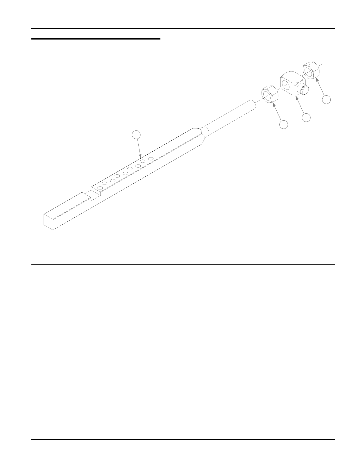
Fuel Valve Kit - 353748
1
5
3
1
HUSTLER Z
TRACTOR
7
6
4
EXISTING
HARDWARE
EXISTING
HARDWARE
11-4 350165 5/02
Page 83

Fuel Valve Kit - 353748
INDEX NO.
1 745059 745059 1 3-WAY FUEL VALVE
2 347989 347989 1 FUEL SHUT-OFF BRACKET
3 767954 767954 1 FW .406 X .812 X .060 SAE HD ZN
4 036244 036244 1 CS .375-16 X 1.00 HX G5 ZN
5 015818 015818 1 FUEL LINE 50"
6 015818 015818 1 FUEL LINE 7"
7 015818 015818 FUEL LINE 21"
SERVICE
PART NO.
000331 000331 5 BLACK CABLE TIE
MFG. PART
NO.
QTY DESCRIPTION
NOTES:
350165 5/02 11-5
Page 84

11-6 350165 5/02
Page 85

Numerical Index
Part Page
No. No.
Index
Numerics
000323 5-5
000331 5-5
000398 5-5
005116 4-7
008417 4-13
008573 7-5
008805 7-16
011320 7-3
012005 7-16
015495 4-5
015818 5-5
016527 5-3
016972 4-12
017004 5-3
017152 4-12
018861 4-7
019521 6-4
024927 4-3
025296 4-11
026237 5-7
027912 1-1
027920 1-1
028118 4-11
029868 4-3
029876 4-3
030601 4-11
030817 5-3
031997 6-6
032763 3-3
032771 3-3
034272 3-3
034280 4-3
034843 7-16
035808 7-9
036236 4-7
036244 4-7
039677 6-4
041152 4-7
041475 6-3
041707 3-3
044255 5-3
045088 5-5
, 10-3
, 7-9, 7-11, 7-15
, 7-7, 7-13, 2-2,
2-3
, 7-17
, 4-11, 7-3, 7-5,
7-7, 7-9, 7-11, 7-13,
7-15
, 5-5, 7-5, 7-9,
7-11, 7-15
, 7-5, 7-9, 7-11,
7-15
, 6-5
, 4-11, 5-3
, 6-3, 8-3
, 3-3
, 7-5, 7-9, 7-11,
7-15
, 5-3
, 7-3, 7-7, 7-13
, 4-3, 4-5, 4-7,
5-3, 10-3
, 7-17
, 4-11, 5-5, 7-3,
7-7, 7-13, 10-3, 2-2,
2-3
Part Page
No. No.
045765 6-3
045898 5-7
051169 8-3
052837 5-3
052860 2-3
053199 4-7
054502 4-7
055749 4-5
055822 4-7
055939 4-3
055947 3-3
058776 4-3
059832 4-7
061077 6-5
061101 4-11
063198 4-7
064006 5-3
064337 4-8
065516 4-7
068239 6-6
068478 1-1
068551 4-7
070037 7-5
072272 7-17
075291 7-5
076745 4-7
077123 7-16
078378 7-9
078386 7-5
080358 10-3
083022 5-7
083196 4-11
083279 9-3
086660 2-3
212076 4-11
212472 7-5
305615 2-3
317073 7-13
318626 7-3
325308 4-11
344267 6-3
344796 2-3
344929 2-3
344945 2-3
346023 2-2
346056 2-2
346411 2-2
347195 7-13
347443 7-5
, 7-3, 7-7, 7-13,
10-3
, 7-3, 7-7, 7-13
, 4-11, 7-3, 7-7,
7-13, 2-2, 2-3
, 8-3
, 5-5
, 4-11
, 5-3, 5-7
, 5-7
, 7-9, 7-11, 7-15
, 7-9, 7-11, 7-15
, 7-9, 7-11, 7-15
, 4-7, 7-3, 7-7,
7-13, 10-3
, 7-9, 7-11, 7-15
, 7-7, 7-13
, 7-9, 7-11, 7-15
, 6-3, 8-3
, 7-17
Part Page
No. No.
347534 2-2
347898 7-15
347914 7-15
347971 7-13
348276 2-3
348284 4-5
348318 4-5
348375 7-5
348391 4-5
348417 4-3
348458 4-5
348524 7-5
348599 2-2
348714 4-7
348755 4-7
348797 4-7
348862 4-7
348888 4-7
348946 4-7
348979 4-7
348987 4-7
349100 7-7
349266 6-3
349308 5-7
349324 7-3
349381 7-9
349399 7-9
349498 7-5
349522 7-3
349605 2-2
349704 5-3
349761 4-11
349803 7-3
349860 3-3
349944 5-5
350041 10-3
350157 1-1
350264 4-7
350272 4-7
350330 4-7
350371 5-3
350397 4-7
350413 4-7
350421 10-3
350454 4-7
350462 10-3
350561 7-5
350595 7-5
357608 2-2
359547 2-3
360693 5-3
362392 4-11
, 4-8
, 4-8
, 7-7
, 7-11
, 7-11
, 7-9, 7-11, 7-15
, 7-7
, 7-7, 7-13
, 4-8
, 7-9, 7-11, 7-15
, 7-11, 7-15
350165 5/02 i-1
Page 86

Part Page
No. No.
Part Page
No. No.
Part Page
No. No.
362657 2-2
373191 7-5
387035 6-3
426296 7-9
504365 7-9
520627 7-9
538850 7-5
545277 7-7
545285 2-2
545343 7-13
545350 2-2
545764 7-3
545806 2-2
704163 4-7
704643 4-5
704742 3-3
704932 5-7
705178 4-7
705186 3-3
705954 6-3
712257 5-7
712976 6-3
714998 5-7
718791 4-7
720177 5-3
722199 10-3
724716 10-3
727016 9-3
727172 9-3
727420 9-4
727438 9-4
727453 9-4
728550 7-9
728568 7-9
740696 4-3
744276 4-3
747741 6-4
747782 6-3
747832 6-4
748681 4-11
748756 10-3
752386 7-9
753798 7-9
756270 4-5
760199 4-7
760637 9-4
762195 5-7
763391 4-11
763946 3-3
763953 3-3
765339 4-7
766204 7-17
, 7-9, 7-11, 7-15
, 7-16
, 8-3
, 9-4, 9-5
, 9-5
, 9-5
, 9-5
, 7-15
, 7-15
, 9-5
767954 2-3
7-3, 7-7, 7-13, 10-3,
2-2, 2-3
767962 5-3
7-5, 7-7, 7-9, 7-11,
7-13, 7-15
768127 4-11
768168 7-15
768333 3-3
768341 1-1
768515 3-3
5-7
768523 3-3
10-3
768820 4-3
769166 5-3
770842 7-15
770859 6-5
771428 4-3
771436 9-3
772079 1-1
776476 5-7
777391 1-1
777656 5-3
778365 5-7
778423 1-1
778738 4-11
778985 3-3
779132 3-3
779280 9-3
779652 7-9
779660 7-5
779850 4-3
779876 4-11
780155 1-1
780171 1-1
780775 5-3
780783 5-3
780841 5-3
781039 4-11
781047 3-3
781054 3-3
781062 3-3
781088 4-7
781104 10-3
781112 4-7
781138 4-12
781153 4-7
781161 5-5
781179 5-5
781187 4-12
781203 4-13
781211 4-7
781229 4-5
, 4-7, 4-11, 5-5,
, 5-5, 6-6, 7-3,
, 3-3
, 4-7, 4-11, 5-3,
, 4-3, 4-7, 5-3,
, 5-3
, 5-3
, 7-9
, 4-8
781237 6-5
781245 6-5
781252 6-5
781260 4-7
781286 4-7
781294 4-5
781302 4-11
7-15
781310 1-1
781328 7-9
781351 4-7
781385 7-5
781401 4-12
781419 9-4
781427 9-3
781435 9-3
781443 1-1
781450 5-3
781469 3-3
781476 3-3
781484 3-3
781492 3-3
781500 3-3
781518 3-3
781526 3-3
781534 3-3
781542 3-3
781559 3-3
781567 6-6
781575 3-3
781583 4-7
781591 3-3
781617 7-5
781633 5-5
781658 3-3
781666 7-17
781674 9-3
781682 7-9
781708 7-3
781716 4-7
781724 5-3
781732 5-3
781765 4-7
781831 4-5
781849 10-3
781856 4-11
7-15
781872 4-11
7-15
781880 2-3
10-3
781898 1-1
781918 4-11
781922 4-7
, 7-5, 7-9, 7-11,
, 7-9, 7-11
, 7-11
, 7-9, 7-11, 7-15
, 9-5
, 4-11
, 7-3, 7-7, 7-13
, 7-9, 7-11, 10-3
, 7-15
, 7-7, 7-13
, 4-8
, 7-5, 7-9, 7-11,
, 7-5, 7-9, 7-11,
, 7-3, 7-7, 7-13,
, 7-15
i-2 350165 5/02
Page 87

Part Page
No. No.
Part Page
No. No.
Part Page
No. No.
781930 4-13
782078 6-5
782086 6-5
782128 9-3
782136 9-3
782144 10-3
782151 10-3
782169 10-3
782177 10-3
782185 10-3
782284 6-5
782292 1-1
782318 5-3
782474 7-5
782516 1-1
782532 7-15
782557 7-11
782649 5-3
782664 5-3
, 7-15
, 7-9, 7-11, 7-15
, 7-11
782771 6-4
782979 4-7
782995 4-5
783001 4-5
783472 10-3
783738 7-5
783787 7-15
783829 4-11
783878 7-5
783944 5-5
783977 1-1
784058 6-5
784066 6-5
784181 5-5
784199 7-5
784207 1-1
784223 6-3
784348 5-5
784702 9-3
, 7-9, 7-11, 7-15
, 7-11, 7-15
, 7-5
, 7-11, 7-15
, 7-5
785030 5-7
785188 9-3
785535 9-5
785808 5-7
786277 9-4
786285 9-4
786426 9-3
808493 2-2
926253 1-1
926295 1-1
926311 1-1
926311only 10-3
926345 1-1
926345only 10-3
926451 1-1
926469 1-1
926550 1-1
926568 1-1
, 10-3
, 10-3
350165 5/02 i-3
 Loading...