

Page 1

72" Quadcycler
TM
Quadcycler Deck
Parts Manual
339622 8/06
•••••••
Hustler Turf Equipment
•••••
P.O. Box 7000
•••
Hesston, Kansas
•
67062-2097
Page 2

Page 3

Table of Contents
Chapter 1
General Information . . . . . . . . . . . . . . . . . . . . . . . . . . . . . . . . . . . . 1-1
Chapter 2 Contents
Deck Assembly . . . . . . . . . . . . . . . . . . . . . . . . . . . . . . . . . . . . . . . . 1-2
Deck Subassembly . . . . . . . . . . . . . . . . . . . . . . . . . . . . . . . . . . . . . 1-4
Spindle Assembly - 506212 . . . . . . . . . . . . . . . . . . . . . . . . . . . . . . 1-7
Chapter 3 Contents
Gauge Arm Assembly - 466888 . . . . . . . . . . . . . . . . . . . . . . . . . . . 3-2
Chapter 4 Contents
Gearbox Breakdown - 532861 (WSI) . . . . . . . . . . . . . . . . . . . . . . . 4-2
Gearbox Breakdown - 532861 (Agrigear) . . . . . . . . . . . . . . . . . . . . 4-4
Chapter 5 Contents
Air Deflector Kit - 470344 . . . . . . . . . . . . . . . . . . . . . . . . . . . . . . . . 5-2
Floatation Kit - 469189 . . . . . . . . . . . . . . . . . . . . . . . . . . . . . . . . . . 5-4
Chapter 6 Contents
Decal Group . . . . . . . . . . . . . . . . . . . . . . . . . . . . . . . . . . . . . . . . . . 6-2
Index . . . . . . . . . . . . . . . . . . . . . . . . . . . . . . . . . . . . . . . . . . . . . . . . . . . . . . . . i-1
336229 9/00
Page 4

336229 9/00
Page 5

Chapter 1
General Information
This manual covers 72” Quadcycler Deck model: 925107
Frequently Ordered Parts
PART NO. DESCRIPTON
084178 Double Angle V-Belt
754853 24" Blade
506212 Spindle Housing Assembly
Service Literature
PART N O DESCRIPTION
084210 72" Quadcycler Owner’s Manual
033514 72” Quadcycler Deck Assembly Instructions
Note: When ordering parts, you must use the service part number as shown for each part, not the index number.
Always give the tractor model and serial number and the engine model and serial number to your parts and service rep
resentative.
Note: Items sold in bulk such as seals and hoses are sold by the foot.
Using this manual
Illustrations used were current at the time of printing, but subsequent production changes may cause your machine to
vary slightly in detail. Excel Industries, Inc. reserves the right to redesign and change the machine as deemed neces
sary, without notification. If a change has been made to your machine which is not reflected in this parts manual, see
your Hustler dealer for current information and parts.
-
-
339622 8/06 1-1
Page 6

Hardware Description Codes & Abbreviations
The following codes are used throughout this parts manual. Refer to this list when ordering parts..
ABBREVIATION DESCRIPTION
CB Carriage Bolt
CE Clevis Pin
CP Cotter Pin
CS Cap Screw
CW Cup Washer
FDRW Fender Washer
FW Flat Washer
HX Hex Head
ID Inside Diameter
LW Lock Washer
MB Machine Bushing
MS Machine Screw
NT Nut
OD Outside Diameter
SC Self Tapping Cap Screw
SH Socket Head
SB Shoulder Bolt
SS Set Screw
Standard Torques
The following chart lists the standard torque values for the threaded fasteners found in this manual. Torque all cap
screws, nuts and set screws to these values unless a different torque is shown in the Notes section next to the fastener.
SIZE FT-LBS NM SIZE FT-LBS NM
.250 8.2 11.1 M3 1 1.3
.312 17 23 M4 2.2 3
.375 30 40 M5 4.5 6.1
.438 48 65 M6 7.7 10.4
.500 73 99 M8 18.5 25
.562 105 143 M10 37 50
.625 145 200 M12 64 87
.750 260 350 M16 160 215
.875 420 565 M20 320 435
1.00 625 850 M24 555 750
NOTE:
Lubricate all grease zerks
1-2 339622 8/06
Page 7

Chapter 2 Contents
Deck Assembly . . . . . . . . . . . . . . . . . . . . . . . . . . . . . . . . . . . . . . . . . 2-2
Deck Subassembly . . . . . . . . . . . . . . . . . . . . . . . . . . . . . . . . . . . . . . 2-4
Spindle Assembly . . . . . . . . . . . . . . . . . . . . . . . . . . . . . . . . . . . . . . . 2-7
339622 8/06 2-1
Page 8
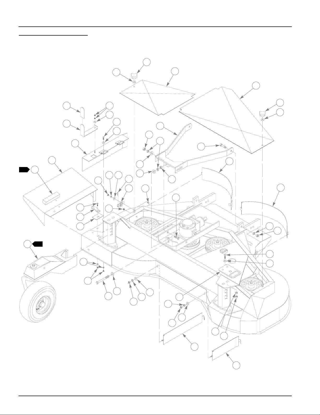
Deck Assembly
1
2
28
19
20
29
33
22
23
20
31
30
8
9
11
32
17
18
21
15
1
16
25
26
3
4
1
2
5
7
6
13
8
14
10
38
27
2
24
19
11
12
19
24
20
37
24
20
19
7
8
34
35
7
8
36
9
2-2 339622 8/06
Page 9

Deck Assembly
INDEX
NO.
10 028274 028274 2 CB .50-13 X 1.50 FULL ZN
11 058875 058875 2 MB .510 X .870 X .050 ZN
12 025601 025601 1 CS .50-13 X 4.620 ZN
13 467266 467266 1 RIGHT REAR DISCHARGE DOOR
14 467241 467241 1 CENTER REAR DISCHARGE DOOR
15 474445 474452 1 DEFLECTOR
16 054528 054528 1 BUMPER
17 074559 074559 1 GRIP
18 467258 467258 1 HANDLE
19 024927 024927 10 NT .25-20 HX G5 ZN
20 017079 017079 7 FW .250 X .560 X .040 SAE ZN
21 467274 467274 1 SIDE DISCHARGE COVER
22 055939 055939 4 CS .25-20 X .750 HX G5 ZN
23 089789 089789 4 FW .266 X .750 X .060 ZN
24 017038 017038 8 LW .250 MEDIUM SPRING ZN
25 056077 056077 2 CS .25-20 X 1.00 HX G5 ZN
26 287649 287649 1 SIDE DISCHARGE CLIP
27 315465 315465 1 CLIP PLATE
28 035626 035626 4 NT 10-24 HX ZN
29 056176 056176 4 LW #10 MEDIUM SPRING ZN
30 758821 758821 2 OVER CENTER LATCH
31 025320 025320 2 HP .091 X 1.875 ZN
32 016048 016048 4 MS 10-24 X .625 TH SL ZN
33 467118 467118 4 PLUG BUTTON
34 467175 467175 1 R/H MULCHER BAFFLE
35 467167 467167 1 L/H MULCHER BAFFLE
36 016527 016527 2 CS .50-13 X 1.00 HX G5 ZN
37 537175 480228 2 TIE DOWN BRACKET
38 N/A 466888 2 GAUGE ARM ASSEMBLY
SERVICE
PART N O .
1 075291 075291 2 CLAMPING KNOB
2 076547 076547 2 FW .344 X .688 X .065 SAE ZN
3 307124 307140 1 R/H DECK COVER
4 307132 307157 1 L/H DECK COVER
5 467126 467126 1 ADJUSTER ARM
6 074252 074252 2 CS .50-13 X 1.50 HX G5 ZN
7 017046 017046 7 LW .50 MEDIUM SPRING ZN
8 008193 008193 7 NT .50-13 HX G5 ZN
9 017137 017137 4 FW .560 X 1.370 X .109 SAE ZN
MFG. PART
NO.
QTY. DESCRIPTION
NOTES:
1. Supplied with item 15 but may be ordered separately.
2. See Chapter 3 for breakdown.
339622 8/06 2-3
Page 10
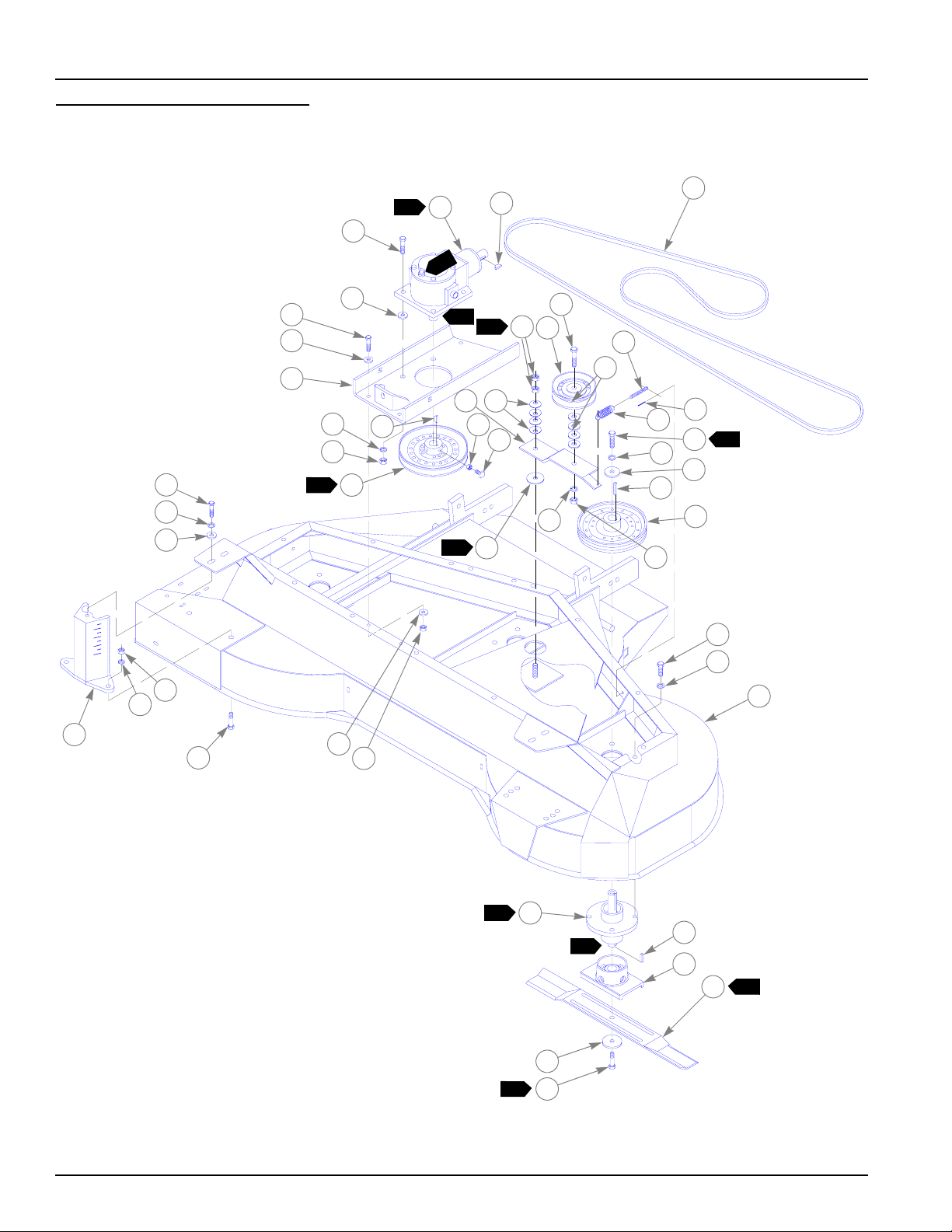
Deck Subassembly
36
5
20
12
13
8
4
4
7
2
24
1
1
3
8
5
18
6
19
22
20
16
15
5
7
6
11
10
21
23
3
25
5
26
1
9
5
6
17
27
28
6
29
37
5
6
5
1
13
2
14
2
30
7
31
32
9
33
34
3
35
2-4 339622 8/06
Page 11

Deck Subassembly
INDEX
NO.
10
SERVICE
PART N O .
1 532820 467316 1 72" 4-WAY DECK ASSEMBLY
2 074252 074252 8 CS .50-13 X 1.50 HX G5 ZN
3 028118 028118 4 FW .620 X 1.00 X .134 ZN
4 532861 466664 1 GEARBOX
5 017046 017046 26 LW .50 MEDIUM SPRING ZN
6 008193 008193 11 NT .50-13 HX G5 ZN
7 036715 036715 2 WOODRUFF KEY
8 467100 467100 1 GEARBOX SUPPORT
9 467324 467324 1 PULLEY 8”
10 042051 042051 2 SS .375-16 X 1.00 SQ-HD ZN
11 706168 706168 2 NT .375-16 HX JAM G5 ZN
12 773242 773242 4 CS .437-14 X 1.250 HX G5 ZN
13 773259 773259 8 FW .50 X 1.250 X .064/.104 SAE F436 ZN
14 041707 041707 4 NT .437-14 HX G5 ZN
15 068759 068759 4 CW .560 X 1.340 X .050 PN
16 315291 315291 1 IDLER ARM BRACKET
17 263517 263517 1 BEARING DISC
18 078949 078949 1 CS .50-13 X 2.00 G5 ZN
19 503748 503748 1 IDLER PULLEY
20 017137 017137 6 FW .560 X 1.370 X .109 SAE ZN
21 036384 036384 1 IDLER SPRING
22 244384 244384 1 IDLER CHAIN
23 017277 017277 1 CP .187 X 1.00 LG HML ZN
24 084178 084178 1 DOUBLE ANGLE V-BELT
25 078378 078378 3 CS .50-20 X 1.50 HX G5 ZN
26 078386 078386 3 FW .510 X 1.750 X .187 ZN
27 212076 212076 3 KEY .250 X .250 X 1.50
28 504142 504142 3 DRIVE PULLEY 8"
29 016527 016527 12 CS .50-13 X 1.00 HX G5 ZN
30 506212 249318 3 SPINDLE HOUSING ASSEMBLY
31 712372 712372 3 KEY .250 X .250 X .660
32 035808 035808 3 BLADE SADDLE
33 754853 754853 3 24" BLADE
34 752386 752386 3 CW .515 X 2.250 X .204 ZN
35 753798 753798 3 CS .50-20 X 1.750 HX G5 ZN
36 705954 705954 2 CS .50-13 X 1.250 HX G5 ZN
37 532887 466631 2 GAUGE ARM MOUNT
MFG. PART
NO.
QTY. DESCRIPTION
339622 8/06 2-5
Page 12

Deck Subassembly
1. Item 9, pulley, must be in the same horizontal plane as the item 28, drive
pulleys, within ± .03" tolerance.
2. Assemble item 30, spindle housing, so the grease zerk faces the front of
the deck.
3. Torque to 65-75 Ft. Lbs.
4. Item 4, gearbox, to be filled to center of sight gauge upon installation
with Amaco 80W-10 or equivalent gear lube.
5. Tighten item 6, nut, to 20 Ft. Lbs. then loosen 1/4 turn.
6. Apply lubrication to both sides of bearing disc. Use Vasoline or 716555
grease.
7. Shaft & exposed end of bearings must be free of rust & wiped clean.
Then coat entire shaft & exposed end of bearings with antiseize
lubricant 705715.
8. Wipe clean & coat entire surface of shaft with antiseize lubricant
705715.
NOTES:
9. To check proper blade alignment, both ends of center blade must align
with both end of outer blades. When blade tips are closest together they
must be within .20" vertically.
10. See 2-7 for breakdown.
11. Air vent must be free of paint.
2-6 339622 8/06
Page 13

Spindle Assembly - 506212
1
2
3
4
1
INDEX
NO.
SERVICE
PART N O .
1 077123 N/A 2 BEARING
2 712364 N/A 1 SPINDLE SHAFT
3 034843 N/A 1 SPINDLE HOUSING
4 012005 N/A 1 GREASE ZERK
MFG. PART
NO.
QTY. DESCRIPTION
339622 8/06 2-7
Page 14

2-8 339622 8/06
Page 15

Chapter 3 Contents
Gauge Arm Assembly . . . . . . . . . . . . . . . . . . . . . . . . . . . . . . . . . . . . 3-2
339622 8/06 3-1
Page 16

Gauge Arm Assembly - 466888
6
23
20
24
26
25
22
5
7
19
1
2
3
4
5
6
5
4
8
25
21
1
10
14
9
11
12
13
2
11
10
17
1
15
16
3
18
4
3-2 339622 8/06
Page 17

Gauge Arm Assembly - 466888
INDEX
NO.
SERVICE
PART NO.
1 016527 016527 1 CS .50-13 X 1.00 HX G5 ZN
2 017046 017046 1 LW .50 MEDIUM SPRING ZN
3 344267 344267 1 FW .510 X 2.150 X .187 SPL ZN
4 082180 082180 2 MB 1.00 X 1.50 X .049 PN
5 077123 077123 2 BEARING
6 310185 310185 1 SPACER
7 532911 083584 1 GAUGE WHEEL ARM
8 506428 506428 1 GAUGE WHEEL FORK
9 049148 049148 1 OIL SEAL
10 049155 049155 2 BEARING
11 049163 049163 2 BEARING CUP
12 747410 747410 1 GAUGE WHEEL 6 X 3.5
13 019521 019521 1 VALVE STEM
14 747402 747402 1 TIRE 13 X 5 X 6
15 048850 048850 1 MACHINE BUSHING
16 048868 048868 1 NT .75-16 HXSL PN
17 011387 011387 1 CP .125 X 1.250 LG HML ZN
18 049171 049171 1 DUST CUP
19 017350 017350 1 SS .25-20 X .250 SH BO
20 466698 466698 1 GAUGE WHEEL ARM HANDLE
21 315226 315226 1 HANDLE PIN
22 466680 466680 1 LOCK LINKAGE
23 315234 315234 1 LINKAGE PIN
24 017277 017277 1 CP .187 X 1.00 LG HML ZN
25 068759 068759 15 CW .560 X 1.340 X .050 PN
26 466672 466672 1 LOCK PIN
747428 747428 TIRE & WHEEL ASSEMBLY (INCLUDES ITEMS 11-14)
MFG. PART
NO.
QTY. DESCRIPTION
NOTES:
1. Pack wheel bearings thoroughly with grease before installing.
2. Fill wheel hub cavity between bearings approximately 2/3 full with
grease.
3. To adjust wheel bearing, raise wheel off floor, tighten item 16, nut, while
rotating the wheel, until there is a slight bind to be sure all bearing
surfaces are in contact.Then back off nut 1/6-1/4 turn to nearest locking
hole or sufficiently to allow wheel to rotate freely within limits of .001".010" (ref) end play. Lock nut at this position by installing cotter pin.
4. Fill cap 3/4 full with grease then press into wheel hub.
5. Do not fully spread item 24, cotter pin, for quicker adjustment of
washers.
6. Use as spares.
339622 8/06 3-3
Page 18

3-4 339622 8/06
Page 19

Chapter 4 Contents
Gearbox Breakdown (532861 WSI). . . . . . . . . . . . . . . . . . . . . . . . . . 4-2
Gearbox Breakdown (532861 Agrigear) . . . . . . . . . . . . . . . . . . . . . . 4-4
339622 8/06 4-1
Page 20

Gearbox Breakdown - 532861 (WSI)
WSI P/N TAG
1
2
3
4
24
23
5
7
8
9
10
6
5
13
16
17
19
6
5
2
1
22
9
20
18
6
11
12
14
15
11
21
4-2 339622 8/06
Page 21

Gearbox Breakdown - 532861 (WSI)
INDEX
NO.
10 045567 N/A 1 CROSS SHAFT
11 045476 N/A 3 RETAINING RING
12 045450 N/A A/R SHIM .003
13 N/A 1 CASE
14 035345 N/A 2 PLUG .25 NPT
15 045658 N/A 1 SHAFT SEAL
16 045518 N/A A/R SHIM .003
17 045682 N/A 1 NT .625-18 HX NL
18 017145 N/A 1 MB .62 X 1.12 X .08 PN
19 045526 N/A 1 L/H GEAR
20 045575 N/A 1 PINION HOUSING
21 049106 N/A 1 BEARING CUP
22 048991 N/A 1 BEARING CONE
23 045559 N/A 1 PINION SHAFT
24 045666 N/A 1 SHAFT SEAL
SERVICE
PART N O .
1 036707 N/A 8 CS .312-18 X .875 HX G5 BO
2 017004 N/A 8 LW .312 MEDIUM SPRING ZN
3 036046 N/A 1 RELIEF VALVE
4 046656 N/A 1 END PLATE
5 045633 N/A 3 BEARING CUP
6 045641 N/A 3 BEARING CONE
7 045484 N/A 1 RING SEAL
8 045534 N/A 1 R/H GEAR
9 081752 N/A 2 WOODRUFF KEY
045468 N/A A/R SHIM .005
045443 N/A A/R SHIM .02
045500 N/A A/R SHIM .005
045492 N/A A/R SHIM .02
MFG. PART
NO.
QTY. DESCRIPTION
NOTES:
339622 8/06 4-3
Page 22

Gearbox Breakdown - 532861 (Agrigear)
2
1
4
3
24
23
12
22
21
6
7
8
9
11
6
12
18
19
7
6
20
7
1
5
10
7
13
14
15
16
17
25
6
4-4 339622 8/06
Page 23

Gearbox Breakdown - 532861 (Agrigear)
INDEX
NO.
10 034736 N/A 1 GEAR SHAFT
11 036673 N/A 1 GEAR SHAFT SPACER
12 036624 N/A 2 SEAL
13 N/A 1 CASE
14 740829 N/A 1 SIGHT GLASS
15 036665 N/A 2 SEAL CAP SHIM
16 036558 N/A 1 SEAL CAP
17 055939 N/A 4 CS .25-20 X .750 HX G5 ZN
18 036632 N/A 2 CARRIER SHIM
19 034751 N/A 1 PINION SHAFT (19 TEETH)
20 036533 N/A 1 PINION CARRIER
21 036681 N/A 1 LOCK WASHER
22 036699 N/A 1 LOCK NUT
23 036657 N/A 2 SEAL CAP SHIM
24 036541 N/A 1 CARRIER SEAL CAP
25 036723 N/A 4 MS 10-24 X .750 FT SH BO
SERVICE
PART N O .
1 036707 N/A 8 CS .312-18 X .875 HX G5 BO
2 036046 N/A 1 RELIEF VALVE
3 036731 N/A 1 REDUCER BUSHING
4 036525 N/A 1 BEARING CAP
5 036640 N/A 2 BEARING CAP SHIM
6 036608 N/A 4 BEARING CUP
7 036616 N/A 4 BEARING CONE
8 034769 N/A 1 GEAR (25 TEETH)
9 036715 N/A 1 WOODRUFF KEY
MFG. PART
NO.
QTY. DESCRIPTION
NOTES:
339622 8/06 4-5
Page 24

4-6 339622 8/06
Page 25

Chapter 5 Contents
Air Deflector Kit - 470344. . . . . . . . . . . . . . . . . . . . . . . . . . . . . . . . . . 5-2
Floatation Kit - 469189. . . . . . . . . . . . . . . . . . . . . . . . . . . . . . . . . . . . 5-4
339622 8/06 5-1
Page 26

Air Deflector Kit - 470344
72" QUADCYCLER DECK
4
5
4
5
4
1
2
2
9
1
2
2
8
1
7
4
5
1
2
4
5
1
6
1
2
1
3
5-2 339622 8/06
Page 27

Air Deflector Kit - 470344
INDEX
NO.
SERVICE
PART N O .
1 034280 N/A 7 CS .312-18 X .750 HX G5 ZN
2 076547 N/A 9 FW .344 X .688 X .065 ZN
3 471318 N/A 1 LEFT SIDE AIR DEFLECTOR
4 017004 N/A 9 LW .312 MEDIUM SPRING ZN
5 034272 N/A 9 NT .312-18 HX G5 ZN
6 471292 N/A 1 CENTER AIR DEFLECTOR
7 471300 N/A 1 RIGHT SIDE AIR DEFLECTOR
8 079186 N/A 2 CS .312-18 X 1.250 HX G5 ZN
9 471326 N/A 1 FILL PANEL
MFG. PART
NO.
QTY. DESCRIPTION
NOTES:
1. After installation, the 3 air deflectors should be positioned .25" above
blade tips.
2. Part installed when High Lift Bac Vac blower is used.
339622 8/06 5-3
Page 28

Floatation Kit - 469189
4
3
8
10
12
4
3
6
7
14
5
9
11
7
13
1
4
3
2
1
18
72" QUADCYCLER DECK
3
4
1
15
16
17
15
5-4 339622 8/06
Page 29

Floatation Kit - 469189
INDEX
NO.
10 469924 N/A 4 SPACER .250
11 469882 N/A 2 SPACER .50
12 469916 N/A 6 SPACER 1.00
13 470674 N/A 2 CASTER MOUNT
14 089938 N/A 2 CS .50-13 X 4.00 HX G5 ZN
15 025296 N/A 4 FW .760 X 1.625 X .080 ZN
16 025288 N/A 2 CASTER WHEEL
17 025262 N/A 2 SPANNER BUSHING
18 023317 N/A 2 NT .50-13 UNT LK G5 ZN
SERVICE
PART N O .
1 705954 N/A 8 CS .50-13 X 1.250 HX G5 ZN
2 533877 N/A 1 RIGHT SIDE CASTER ARM
3 017046 N/A 8 LW .50 MEDIUM SPRING ZN
4 008193 N/A 8 NT .50-13 HX G5 ZN
5 527788 N/A 1 LEFT SIDE CASTER ARM
6 078634 N/A 2 LINCH PIN
7 045765 N/A 4 FW 1.060 X 1.50 X .134 ZN
8 015495 N/A 2 GREASE FITTING
9 018747 N/A 4 BRONZE BUSHING
MFG. PART
NO.
QTY. DESCRIPTION
NOTES:
339622 8/06 5-5
Page 30

Floatation Kit - 469189
9
SPRING
BRACKET
6
5
7
2
1
4
10
8
72‘” QUADCYCLER DECK
3
5-6 339622 8/06
Page 31

Floatation Kit - 469189
INDEX
NO.
10 370494 N/A 2 DECK SPRING STRAP
SERVICE
PART N O .
1 036236 N/A 2 CS .312-18 X 1.00 HX G5 ZN
2 470708 N/A 1 TIGHTENER
3 034272 N/A 2 NT .312-18 HX G5 ZN
4 025502 N/A 1 SPRING TIHGTENER
5 334052 N/A 1 LOWER SPRING MOUNT
6 735670 N/A 1 TIGHTENER DECAL
7 011379 N/A 3 DECK SPRING
8 370452 N/A 1 UPPER SPRING MOUNT
9 023036 N/A 3 HAIRPIN
MFG. PART
NO.
QTY. DESCRIPTION
NOTES:
339622 8/06 5-7
Page 32

Floatation Kit - 469189
5
2
4
3
EXISTING
HARDWARE
1
72" QUADCYCLER DECK
EXISTING
HARDWARE
2
1
3
4
5-8 339622 8/06
Page 33

Floatation Kit - 469189
INDEX
NO.
SERVICE
PART N O .
1 728550 N/A 2 SB .50 X .750 SH .375-16 TD ZN
2 058875 N/A 8 MB .510 X .870 X .050 ZN
3 712919 N/A 4 FW .406 X 1.00 X .120 HRD ZN
4 016865 N/A 4 NT .375-16 UNT LK ZN
5 740878 N/A 2 SB .50 X 1.00 SH .375-16 TH
MFG. PART
NO.
QTY. DESCRIPTION
NOTES:
1. Discard lock washer and move nut to location shown.
339622 8/06 5-9
Page 34

5-10 339622 8/06
Page 35

Chapter 6 Contents
Decal Group - 925107 . . . . . . . . . . . . . . . . . . . . . . . . . . . . . . . . . . . . 6-2
339622 8/06 6-1
Page 36

Decal Group
LOCATE ALONG CORNER
& EDGE OF STRINGER
AS SHOWN (2 PLACES)
4
3
5
2
.25
2.0
2
1
1
.50
11
.25
8.0
1.0
1.50
5
8.0
20.07
10.25
2.0
3.0
10
1
9
.50
8.0
1.0
1.0
1
8
1
1.50
7
6
6-2 339622 8/06
Page 37

Decal Group
INDEX
NO.
10 727420 727420 1 DEFLECTOR SHIELD DECAL
11 N/A 083279 1 SERIAL NUMBER PLATE
12 757112K N/A 1 DECAL KIT (INCLUDES ITEMS 1-12)
SERVICE
PART N O .
1 727438 727438 3 WHIRLING BLADES DECAL
2 359547 359547 2 STEP TREAD
3 760637 760637 1 MOWER DECK QUICK REFERENCE DECAL
4 727842 727842 1 PTO SHAFT DECAL
5 727453 727453 2 BELT & PULLEY DECAL
6 728519 728519 1 HUSTLER LOGO DECAL
7 727685 727685 1 72” 4-WAY DECK DECAL
8 727917 727917 1 PATENT NUMBER DECAL
9 741264 741264 1 MADE IN U.S.A. DECAL
1. .25 between decals
MFG. PART
NO.
QTY. DESCRIPTION
NOTES:
339622 8/06 6-3
Page 38

6-4 339622 8/06
Page 39

Numerical Index
Part Page
No. No.
Index
Numerics
008193 1-3, 1-5, 5-5
011379 5-7
011387 3-3
012005 1-7
015495 5-5
016048 1-3
016527 1-3, 1-5, 3-3
016865 5-9
017004 4-3, 5-3
017038 1-3
017046 1-3, 1-5, 3-3, 5-5
017079 1-3
017137 1-3, 1-5
017145 4-3
017277 1-5, 3-3
017350 3-3
018747 5-5
019521 3-3
023036 5-7
023317 5-5
024927 1-3
025262 5-5
025288 5-5
025296 5-5
025320 1-3
025502 5-7
025601 1-3
028118 1-5
028274 1-3
034272 5-3, 5-7
034280 5-3
034736 4-5
034751 4-5
034769 4-5
034843 1-7
035345 4-3
035626 1-3
035808 1-5
036046 4-3, 4-5
036236 5-7
036384 1-5
036525 4-5
036533 4-5
036541 4-5
036558 4-5
036608 4-5
036616 4-5
036624 4-5
036632 4-5
036640 4-5
036657 4-5
Part Page
No. No.
036665 4-5
036673 4-5
036681 4-5
036699 4-5
036707 4-3, 4-5
036715 1-5, 4-5
036723 4-5
036731 4-5
041707 1-5
042051 1-5
045443 4-3
045450 4-3
045468 4-3
045476 4-3
045484 4-3
045492 4-3
045500 4-3
045518 4-3
045526 4-3
045534 4-3
045559 4-3
045567 4-3
045575 4-3
045633 4-3
045641 4-3
045658 4-3
045666 4-3
045682 4-3
045765 5-5
046656 4-3
048850 3-3
048868 3-3
048991 4-3
049106 4-3
049148 3-3
049155 3-3
049163 3-3
049171 3-3
054528 1-3
055939 1-3, 4-5
056077 1-3
056176 1-3
058875 1-3, 5-9
068759 1-5, 3-3
074252 1-3, 1-5
074559 1-3
075291 1-3
076547 1-3, 5-3
077123 1-7, 3-3
078378 1-5
078386 1-5
078634 5-5
Part Page
No. No.
078949 1-5
079186 5-3
081752 4-3
082180 3-3
083279 6-3
083584 3-3
084178 1-5
089789 1-3
089938 5-5
212076 1-5
244384 1-5
249318 1-5
263517 1-5
287649 1-3
307124 1-3
307132 1-3
307140 1-3
307157 1-3
310185 3-3
315226 3-3
315234 3-3
315291 1-5
315465 1-3
334052 5-7
344267 3-3
359547 6-3
370452 5-7
370494 5-7
466631 1-5
466664 1-5
466672 3-3
466680 3-3
466698 3-3
466888 1-3
467100 1-5
467118 1-3
467126 1-3
467167 1-3
467175 1-3
467241 1-3
467258 1-3
467266 1-3
467274 1-3
467316 1-5
467324 1-5
469189 5-4, 5-5, 5-6, 5-7,
5-8, 5-9
469882 5-5
469916 5-5
469924 5-5
470344 5-2, 5-3
470674 5-5
336229 9/00 i-1
Page 40

Part Page
No. No.
Part Page
No. No.
Part Page
No. No.
470708 5-7
471292 5-3
471300 5-3
471318 5-3
471326 5-3
474445 1-3
480228 1-3
503748 1-5
504142 1-5
506212 1-5
506428 3-3
527788 5-5
532820 1-5
532861 1-5, 4-2, 4-3, 4-4, 4-5
532887 1-5
532911 3-3
533877 5-5
537175 1-3
705715 1-6
705954 1-5, 5-5
706168 1-5
712364 1-7
712372 1-5
712919 5-9
716555 1-6
727420 6-3
727438 6-3
727453 6-3
727685 6-3
727842 6-3
727917 6-3
728519 6-3
728550 5-9
735670 5-7
740829 4-5
740878 5-9
741264 6-3
747402 3-3
747410 3-3
747428 3-3
752386 1-5
753798 1-5
754853 1-5
757112K 6-3
758821 1-3
760637 6-3
773242 1-5
773259 1-5
925107 6-1
i-2 336229 9/00
 Loading...