

Page 1

Hustler Super Z XR7
Parts Manual
106575 Rev. 7/06
•••••••
Hustler Turf Equipment
•••••
P.O. Box 7000
•••
Hesston, Kansas
•
67062-2097
Page 2
WARNING:
The engine exhaust from this product
contains chemicals known to the State
of California to cause cancer, birth
defects or other reproductive harm.
IMPORTANT: This engine is not equipped with a spark arrester muffler. It is a violation of California Public Resource Code
Section 4442 to use or operate this engine on any fores t-covered, brush-covered, or grass-covered unimproved land. Other
states or federal areas may have similar laws.
This spark ignition system complies with Canadian ICES-002.
The Engine Owner’s Manual provides information regarding the U.S. Environmental Protection Agency (EPA) and the
California Emission Control Regulation of emission systems, maintenance and warranty.
Keep Engine Owner’s Manual with your unit. Should the Engine Owner’s Manual become damaged or illegible, replace immediately. Replacements may be ordered pe r the information found in the Produc t Information sec tion of the
owner’s manual.
Page 3

Chapter 1
General Information . . . . . . . . . . . . . . . . . . . . . . . . . . . . . . . . . . . . 1-1
Chapter 2 Contents
Frame Rivet Nut Installation . . . . . . . . . . . . . . . . . . . . . . . . . . . . . . 2-2
Seat Support Rivet Nut Installation . . . . . . . . . . . . . . . . . . . . . . . . . 2-3
Footrest Assembly . . . . . . . . . . . . . . . . . . . . . . . . . . . . . . . . . . . . . 2-4
Chapter 3 Contents
Hydraulic System Installation–All Air Cooled Engines . . . . . . . . . . 3-2
Hydraulic System Installation–Kawasaki 26HP Engine . . . . . . . . . 3-6
Chapter 4 Contents
Battery Installation. . . . . . . . . . . . . . . . . . . . . . . . . . . . . . . . . . . . . . 4-2
Deck Lift Assembly . . . . . . . . . . . . . . . . . . . . . . . . . . . . . . . . . . . . . 4-4
Steering and Park Brake Assembly . . . . . . . . . . . . . . . . . . . . . . . . 4-6
Pump Belt and Pulleys Installation . . . . . . . . . . . . . . . . . . . . . . . . . 4-10
Chapter 5 Contents
Kawasaki 25 HP Engine Installation . . . . . . . . . . . . . . . . . . . . . . . . 5-2
Kawasaki 26 HP Engine Installation . . . . . . . . . . . . . . . . . . . . . . . . 5-6
Kawasaki 26 HP Engine Installation . . . . . . . . . . . . . . . . . . . . . . . . 5-10
Honda 24 HP Engine Installation . . . . . . . . . . . . . . . . . . . . . . . . . . 5-14
Kohler 27 & 30 HP Engine Installation . . . . . . . . . . . . . . . . . . . . . . 5-18
Kohler 28 HP EFI Engine Installation . . . . . . . . . . . . . . . . . . . . . . . 5-22
Kohler 28 HP EFI Engine Installation . . . . . . . . . . . . . . . . . . . . . . . 5-26
Fuel System–Air Cooled W/Carburetor. . . . . . . . . . . . . . . . . . . . . . 5-30
Fuel System–Liquid Cooled . . . . . . . . . . . . . . . . . . . . . . . . . . . . . . 5-32
Fuel System –With EFI . . . . . . . . . . . . . . . . . . . . . . . . . . . . . . . . . . 5-34
Fuel System –With EFI . . . . . . . . . . . . . . . . . . . . . . . . . . . . . . . . . . 5-36
Instrument Panel Assembly–Air Cooled W/Carb. . . . . . . . . . . . . . . 5-38
Instrument Panel–Liquid Cooled . . . . . . . . . . . . . . . . . . . . . . . . . . . 5-40
Instrument Panel–Liquid Cooled . . . . . . . . . . . . . . . . . . . . . . . . . . . 5-42
Instrument Panel Assembly–With EFI. . . . . . . . . . . . . . . . . . . . . . . 5-44
Instrument Panel Assembly–With EFI. . . . . . . . . . . . . . . . . . . . . . . 5-46
Electrical Schematic - Common Air Cooled (799320). . . . . . . . . . . 5-48
Electrical Schematic - Kawasaki LC (796599) . . . . . . . . . . . . . . . . 5-49
Electrical Schematic - Kawasaki LC (799338) . . . . . . . . . . . . . . . . 5-50
Electrical Schematic - Kohler EFI (789560) . . . . . . . . . . . . . . . . . . 5-51
Electrical Schematic - Kohler EFI (799346) . . . . . . . . . . . . . . . . . . 5-52
Table of Contents
Chapter 6 Contents
Front Wheel Assembly . . . . . . . . . . . . . . . . . . . . . . . . . . . . . . . . . . 6-2
Front Wheel Breakdown–747782 . . . . . . . . . . . . . . . . . . . . . . . . . . 6-4
Optional Semi-Pneumatic Tire/Wheel–789537 . . . . . . . . . . . . . . . . 6-5
Drive Wheel Assembly . . . . . . . . . . . . . . . . . . . . . . . . . . . . . . . . . . 6-6
Anti-Rollover Wheel Assembly . . . . . . . . . . . . . . . . . . . . . . . . . . . . 6-7
Chapter 7 Contents
106575 7/06 c-1
Page 4

72" Side Discharge Deck Assembly . . . . . . . . . . . . . . . . . . . . . . . . 7-2
72" Side Discharge Deck Pulley Assembly . . . . . . . . . . . . . . . . . . 7-4
66" Side Discharge Deck Assembly . . . . . . . . . . . . . . . . . . . . . . . . 7-6
66" Side Discharge Deck Pulley Assembly . . . . . . . . . . . . . . . . . . 7-8
60" Side Discharge Deck Assembly . . . . . . . . . . . . . . . . . . . . . . . 7-10
60" Side Discharge Deck Pulley Assembly . . . . . . . . . . . . . . . . . . 7-12
54" Deck Assembly . . . . . . . . . . . . . . . . . . . . . . . . . . . . . . . . . . . . 7-14
54" Side Discharge Deck Pulley Assembly . . . . . . . . . . . . . . . . . . 7-16
72" Rear Discharge Deck Assembly . . . . . . . . . . . . . . . . . . . . . . . 7-18
72" Rear Discharge Deck Pulley Assembly . . . . . . . . . . . . . . . . . . 7-20
60" Rear Discharge Deck Assembly . . . . . . . . . . . . . . . . . . . . . . . 7-22
60" Rear Discharge Deck Pulley Assembly . . . . . . . . . . . . . . . . . . 7-24
Spindle Assembly–796235 . . . . . . . . . . . . . . . . . . . . . . . . . . . . . . . 7-26
Spindle Assembly–796680 . . . . . . . . . . . . . . . . . . . . . . . . . . . . . . . 7-27
Chapter 8 Contents
Deck Installation–Side Discharge. . . . . . . . . . . . . . . . . . . . . . . . . . 8-2
Deck Installation–Rear Discharge . . . . . . . . . . . . . . . . . . . . . . . . . 8-4
72", 66", & 54" Deck Belt Routing and Tensioning. . . . . . . . . . . . . 8-6
60" Side Discharge Deck Belt Routing and Tensioning . . . . . . . . . 8-7
72" & 60" Rear Discharge Deck Belt Routing and Tensioning . . . . 8-8
Seat Installation . . . . . . . . . . . . . . . . . . . . . . . . . . . . . . . . . . . . . . . 8-10
Chapter 9 Contents
Tractor Decals . . . . . . . . . . . . . . . . . . . . . . . . . . . . . . . . . . . . . . . . 9-2
72", 66" & 60" Side Discharge Deck Decals. . . . . . . . . . . . . . . . . . 9-4
54" Side Discharge Deck Decals . . . . . . . . . . . . . . . . . . . . . . . . . . 9-5
72" and 60" Rear Discharge Deck Decals . . . . . . . . . . . . . . . . . . . 9-6
Chapter 10 Contents
Maintenance & Adjustments Safety Precautions . . . . . . . . . . . . . 10-3
Maintenance . . . . . . . . . . . . . . . . . . . . . . . . . . . . . . . . . . . . . . . . . 10-7
Adjustments . . . . . . . . . . . . . . . . . . . . . . . . . . . . . . . . . . . . . . . . 10-17
Index. . . . . . . . . . . . . . . . . . . . . . . . . . . . . . . . . . . . . . . . . . . . . . . . . . . . . . . . i-1
c-2 106575 7/06
Page 5

Chapter 1
General Information
This Manual covers Hustler XR7 Super Z models: 927467, 927624, 927673, 927681, 927848,
927855, 927871, 927889, 927897, 927913, 927921, 927939, 927947, 927970, 927988, 927996,
928002, 928010, 928028, 928036, 928044, 928051, 928069.
Frequently Ordered Parts
PART NO. DESCRIPTON
027912 Lubrizol 7 oz. Bottle
027920 Lubrizol 10 oz. Bottle
768341 Hydraulic Oil Filter
781443 Pump Drive Belt
797696 Blade, F18.50"-H-F-CW
794685 Blade, F20.50"-H-F-CW (60" Deck)
798496 Blade, F22.50"-H-F-CW (66" Deck)
798702 Blade, F24.50"-H-F-CW(72" Deck)
793794 Blade, 20.50"-L-F-CW
795633 Blade 20.50"-L-F-CCW
796839 Blade, 23.86-L-F-CW
796508 Blade, 23.86-L-F-CCW
797928 Belt, B-Section (54" Deck)
797720 Belt, B-Section (60" Deck)
797936 Belt, B-Section (66" Deck)
784207 Belt, B-Section (72" Deck)
795781 60" Rear Discharge Deck Belt
797167 72" Rear Discharge Deck Belt
068478 Fuel Filter
785261 Main Air Filter Element
785279 Safety Air Filter Element
772079 Kawasaki Engine Oil Filter
785634 Honda Engine Oil Filter
747303 Kohler Engine Oil Filter
Service Literature
PART NO. DESCRIPTION
375527 Owner’s Manual
785642 Honda 18/20/24 Engine Owner’s Manual
778423 Kawasaki 19–25 hp Engine Owner’s Manual
742684 Kohler Engine Owner’s Manual
Note: When ordering parts, you must use the part number as shown for each part, not the index number. Always give
the model and serial number to your parts and service representative.
Note: Items sold in bulk such as seals and hoses are sold by the foot.
106575 7/06 1-1
Page 6

Using this manual
Illustrations used were current at the time of printing, but subsequent production changes may cause your machine to
vary slightly in detail. Excel Industries, Inc. reserves the right to redesign and change the machine as deemed neces
sary, without notification. If a change has been made to your machine which is not reflected in this parts manual, see
your Hustler dealer for current information and parts.
Hardware Description Codes & Abbreviations
The following codes are used throughout this parts manual. Refer to this list when ordering parts.
ABBREVIATION DESCRIPTION
CB
CE
CP
CS
CW
FDRW
FW
HX
LW
MB
MS
NT
SC
SH
SB
SS
OD
ID
Carriage Bolt
Clevis Pin
Cotter Pin
Cap Screw
Cup Washer
Fender Washer
Flat Washer
Hex Head
Lock Washer
Machine Bushing
Machine Screw
Nut
Self Tapping Cap Screw
Socket Head
Shoulder Bolt
Set Screw
Outside Diameter
Inside Diameter
-
Standard Torques
The following chart lists the standard torque values for the threaded fasteners found in this manual. Torque all cap
screws, nuts and set screws to these values unless a different torque is shown in the Notes section next to the fastener.
SIZE FT-LBS NM SIZE FT-LBS NM
.250 8.2 11.1 M3 1 1.3
.312 17 23 M4 2.2 3
.375 30 40
.438 48 65
.500 73 99 M8 18.5 25
.562 105 143
.625 145 200
.750 260 350
.875 420 565
1.00 625 850 M20 320 435
NOTE:
Loctite® 592 to be used on all pipe threads.
Lubricate all grease zerks.
M5 4.5 6.1
M6 7.7 10.4
M10 37 50
M12 64 87
M14 80 108.5
M16 160 215
M24 555 750
1-2 106575 7/06
Page 7

Chapter 2 Contents
Frame Rivet Nut Installation . . . . . . . . . . . . . . . . . . . . . . . . . . . . . . . 2-2
Seat Support Rivet Nut Installation . . . . . . . . . . . . . . . . . . . . . . . . . . 2-3
Footrest Assembly . . . . . . . . . . . . . . . . . . . . . . . . . . . . . . . . . . . . . . . 2-4
106575 7/06 2-1
Page 8
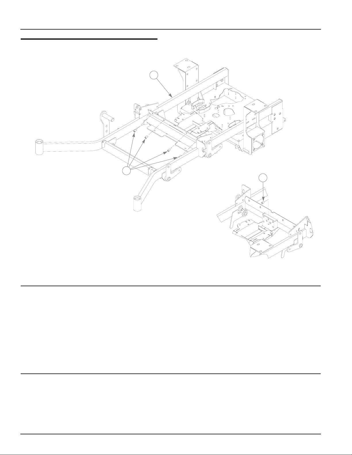
Frame Rivet Nut Installation
1
2
2
INDEX NO.
1 547992 103531 1
2 N/A 808493 10
SERVICE
PAR T NO.
547760 352278 1
547752 103952 1
547984 107616 1
548016 100412 1
548024 101808 1
MFG. PART
NO.
QTY. DESCRIPTION
TRACTOR FRAME (54")
TRACTOR FRAME (60")
TRACTOR FRAME (66")
TRACTOR FRAME (72")
60" RD TRACTOR FRAME
72" RD TRACTOR FRAME
3/8-16 THREAD RIVET NUT
NOTES:
2-2 106575 7/06
Page 9
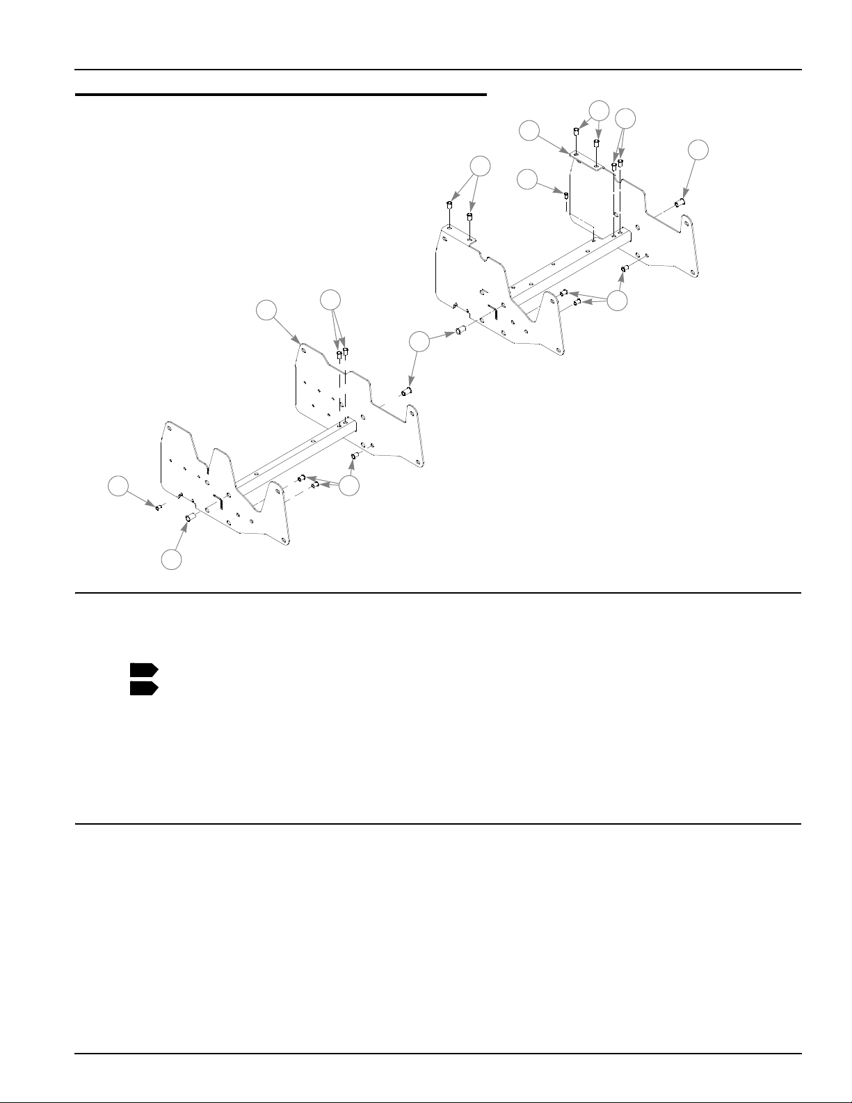
Seat Support Rivet Nut Installation
3
4
2
5
3
6
6
INDEX NO.
1
5
SERVICE
PAR T NO.
1 547950 106732 1
1
2 547968 348615 1
2
3 N/A 808485 4
4 N/A 808493 5
4 N/A 808493 5
5 N/A 600961 8
6 N/A 808477 2
6 N/A 808477 3
MFG. PART
NO.
4
5
4
QTY. DESCRIPTION
XR7 MMZ SEAT SUPPORT
26HP KAWASAKI SEAT SUPPORT
5/16-18 THREAD RIVET NUT (KAWASAKI LIQUID COOLED ONLY)
3/8-16 THREAD RIVET NUT (FOR AIR COOLED)
3/8-16 THREAD RIVET NUT (FOR LIQUID COOLED)
1/2-13 THREAD RIVET NUT (PER EACH SUPPORT)
1/4-20 THREAD RIVET NUT (KAWASAKI AIR COOLED ONLY)
1/4-20 THREAD RIVET NUT (KAWASAKI LIQUID COOLED ONLY)
4
NOTES:
1. Used on all mowers with air cooled engines (service part includes rivet
nuts).
2. Used only on mowers with liquid cooled engines (service part includes
rivet nuts).
106575 7/06 2-3
Page 10
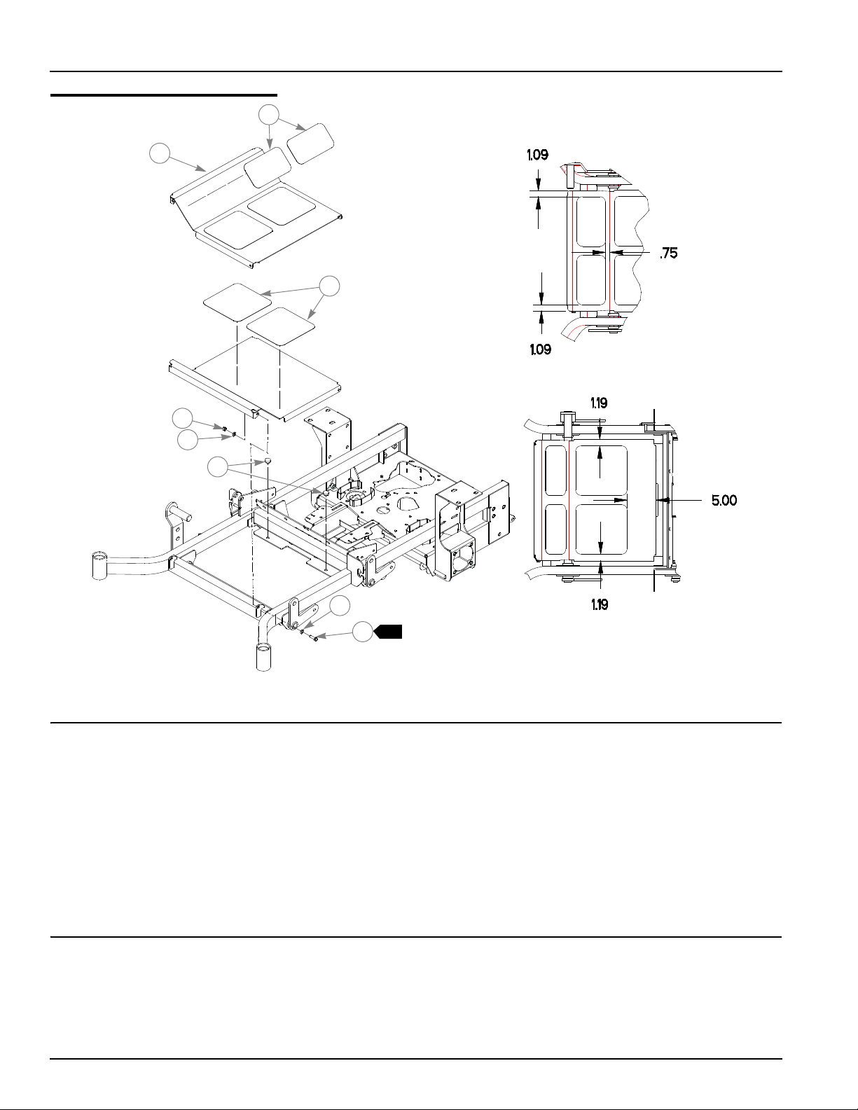
Footrest
Assembly
1
2
3
4
5
6
5
1
7
INDEX
NO.
1 359547 359547 2
2 395533 395533 1
3 305615 305615 2
4 086660 086660 2
5 767954 767954 4
6 781880 781880 2
7 052860 052860 2
SERVICE
PART NO.
MFG.
PART NO.
QTY DESCRIPTION
STEP TREAD
FLOOR
PLATFORM STEP TREAD
NT .375-16 HX LK NY
FW .406 X .812 X .060 SAE HD ZN
RUBBER BUMPER
CS .375-16 X 1.250 HX G5 ZN
NOTES:
1. Do not tighten, Item 2 (395533 Floor) must be able to pivot on these
bolts.
2-4 106575 7/06
Page 11

Chapter 3 Contents
Hydraulic System Installation–All Air Cooled Engines. . . . . . . . . . . . 3-2
Hydraulic System Installation–Kawasaki 26HP Engine . . . . . . . . . . . 3-6
106575 7/06 3-1
Page 12
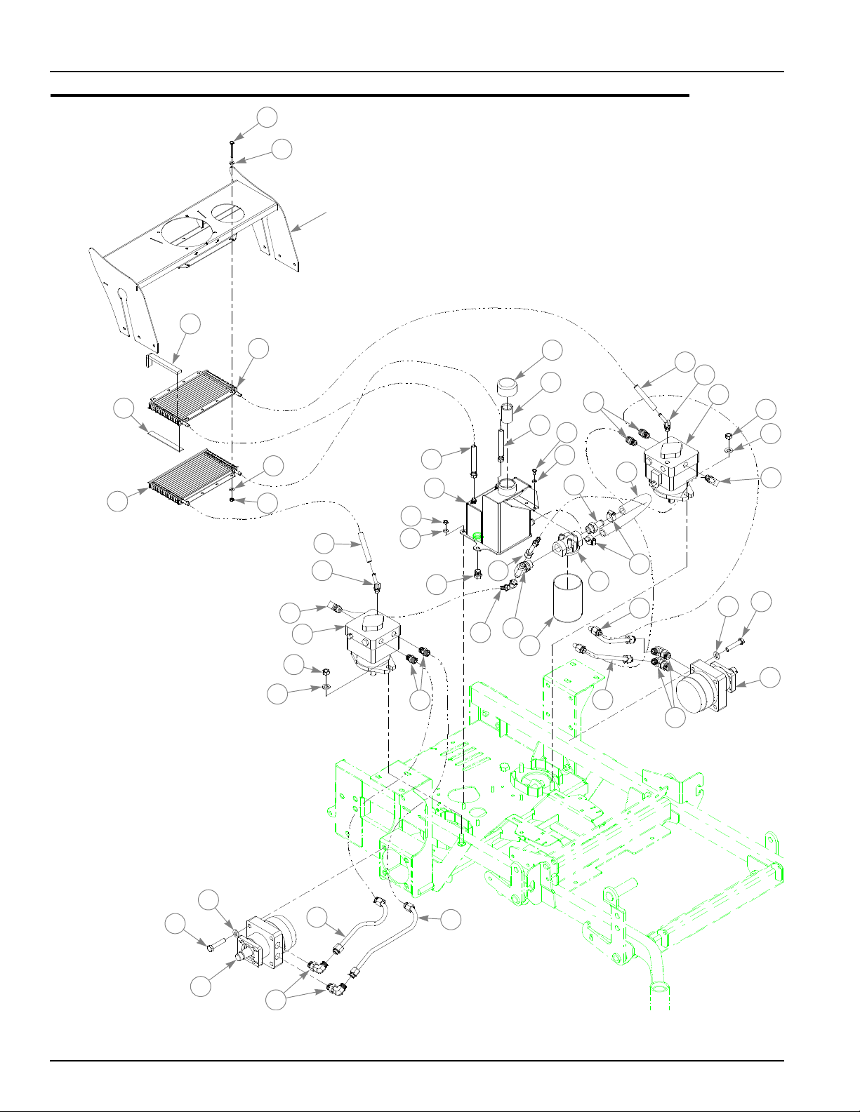
Hydraulic System Installation–All Air Cooled Engines
1
2
SUPER Z
HOOD
3
4
5
11
12
25
21
10
26
28
27
29
2
4
6
22
23
24
13
14
15
17
21
7
8
25
9
2
31
30
20
16
32
33
36
22
23
13
15
14
15
24
18
19
18
19
15
36
35
34
3-2 106575 7/06
Page 13

Hydraulic System Installation–All Air Cooled Engines
INDEX
NO.
10 357616 357616 1 SUPER Z RESERVOIR
11 034272 034272 4 NT .312-18 HX G5 ZNYC
12 768523 768523 4 FW .343 X .687 X .051/.080 HD ZNYC
13 788042 788042 2 PUMP, HYDRO-GEAR BDP-21L-408
14 008193 008193 4 NT .500-13 HX G5 ZNYC
15 767962 767962 12 FW .531 X 1.063 X .090 SAE HD ZN
16 783928 783928 1 ZAF SERIES FILTER HEAD
17 783936 783936 1 FILTER ELEMENT
18 008573 008573 8 CS .500-13 X 2.50 HX G5 ZNYC
19 782383 782383 2 WHITE MOTOR CE782383-18
20 700484 700484 2 HOSE CLAMP
21 784132 N/A 2 RETURN HOSE ASSY, #6 17.375" LONG
22 784124 N/A 2 RETURN HOSE, #6 16.5" LONG
23 784108 N/A 2 FITTING, #6 BEADED TUBE-ORB 45°
24 784082 N/A 2 FITTING, #8 BEADED TUBE-ORB 90°
25 781534 N/A 4 FITTING, STR-8MORB/-8MSL
26 781658 N/A 1 HEX PLUG FITTING, STR-8MORB
27 784025 N/A 1 SUCTION HOSE ASSY, FILTER-PUMP
28 783993 N/A 1 SUCTION HOSE, TANK-FILTER
29 788174 N/A 1 FITTING, T -8MJIC/8MJIC
30 783985 N/A 1 FITTING, 10 FX05-S
31 784116 N/A 1 SUCTION HOSE, #12 16" LONG
32 782870 N/A 1 TUBE, HYDRAULIC LINE
33 782880 N/A 1 TUBE, HYDRAULIC LINE
34 782458 N/A 1 TUBE, HYDRAULIC LINE
35 782441 N/A 1 TUBE, HYDRAULIC LINE
36 781526 N/A 4 FITTING, 90-10MORB/-8MSL
37 N/A 783720 1 HYDRO KIT (INCLUDES ITEMS 21-36)
SERVICE
PART NO.
1 705608 705608 4 CS .250-20 X 2.25 HX G5 ZNYC
2 768515 768515 10 FW .281 X .625 X .051/.080 HD ZNYC
3 713198 713198 2 SEAL 3/8 X 3/4 X 7.25" LONG
4 783704 783704 2 OIL COOLER
5 033035 033035 2 WEATHERSTRIP 1/8 X 3/4 X 5.88" LONG
6 068551 068551 4 NT .250-20 HX NL ZNYC
7 032763 032763 1 BREATHER CAP
8 032771 032771 1 STRAINER
9 055947 055947 2 CS .250-20 X .50 HX G5 ZNYC
MFG. PART
NO.
QTY DESCRIPTION
NOTES:
1. Add 3.5 oz.Lubrizol (027912) to new system or when hydraulic oil is
changed (see Owner’s Manual).
2. Hydraulic system capacity is 5 US quarts. Fill reservoir to within 1" of top
of Item 8 (032771 Strainer).
106575 7/06 3-3
Page 14

HYDRAULIC SYSTEM CHARGING PROCEDURE
1. Set handles in the neutral position.
2. Start engine at idle.
3. Let run for a minimum of 30 seconds.
4. Stroke handles to forward position.
5. If motors do not turn in 15 seconds return handles to neutral and
repeat step 3 and 4 (one time).
6. If motors do not turn after second attempt, shut off the engine
and check for oil at the pump.
7. Increase throttle to half speed and work handles through forward
and reverse position until the motor operates smoothly
throughout the entire speed range.
Note:
Seal Kit for hydraulic pump; 784983 (BDP21L Overhaul Seal Kit).
3-4 106575 7/06
Page 15

This page intentionally left blank.
106575 7/06 3-5
Page 16
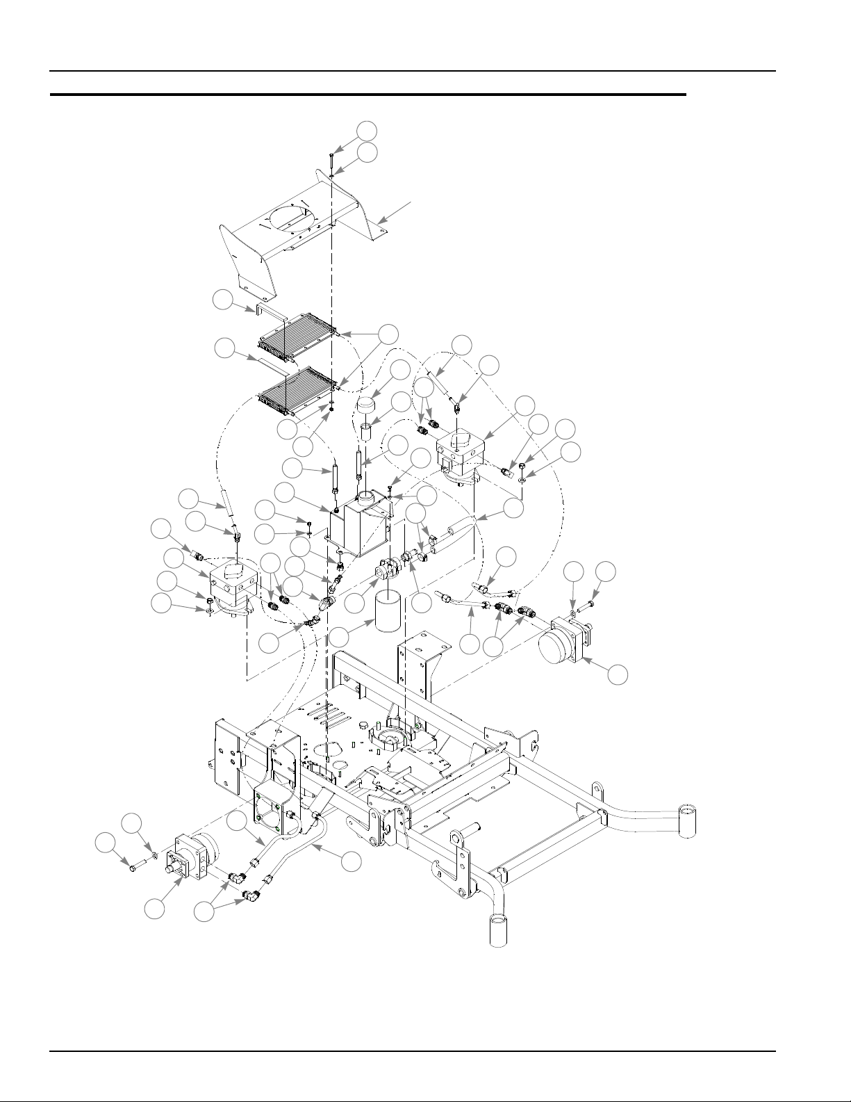
Hydraulic System Installation–Kawasaki 26HP Engine
1
2
KAWASAKI 26HP
HOOD
3
25
15
14
13
23
24
4
2
6
22
9
10
11
27
26
28
30
29
17
5
7
8
21
18
16
26
12
31
23
24
13
25
14
15
2
34
37
33
32
15
19
20
19
15
20
36
35
37
3-6 106575 7/06
Page 17

Hydraulic System Installation–Kawasaki 26HP Engine
INDEX
NO.
10 034272 034272 4 NT .312-18 HX G5 ZNYC
11 768523 768523 4 FW .343 X .687 X .051/.080 HD ZNYC
12 055947 055947 2 CS .250-20 X .50 HX G5 ZNYC
13 788042 788042 2 PUMP, HYDRO-GEAR BDP-21L-408
14 008193 008193 4 NT .500-13 HX G5 ZNYC
15 767962 767962 12 FW .531 X 1.063 X .090 SAE HD ZN
16 783928 783928 1 ZAF SERIES FILTER HEAD
17 783936 783936 1 FILTER ELEMENT
18 700484 700484 2 HOSE CLAMP
19 008573 008573 8 CS .500-13 X 2.50 HX G5 ZNYC
20 782383 782383 2 WHITE MOTOR CE782383-18
21 796920 N/A 1 COOLER-RESERVOIR HOSE ASSY, 25" LONG
22 796912 N/A 1 COOLER-RESERVOIR HOSE ASSY, 29" LONG
23 783993 N/A 1 SUCTION HOSE, TANK-FILTER
24 784108 N/A 2 FITTING, #6 BEADED TUBE-ORB 45°
25 784082 N/A 2 FITTING, #8 BEADED TUBE-ORB 90°
26 781534 N/A 4 FITTING, STR-8MORB/-8MSL
27 781658 N/A 1 HEX PLUG FITTING, STR-8MORB
28 784025 N/A 1 SUCTION HOSE ASSY, FILTER-PUMP
29 783993 N/A 1 SUCTION HOSE ASSY, FILTER-PUMP
30 788174 N/A 1 FITTING, T -8MJIC/8MJIC
31 783985 N/A 1 FITTING, 10 FX05-S
32 784116 N/A 1 SUCTION HOSE, #12 16" LONG
33 782870 N/A 1 TUBE, HYDRAULIC LINE
34 782880 N/A 1 TUBE, HYDRAULIC LINE
35 782458 N/A 1 TUBE, HYDRAULIC LINE
36 782441 N/A 1 TUBE, HYDRAULIC LINE
37 781526 N/A 4 FITTING, 90-10MORB/-8MSL
SERVICE
PART NO.
1 705608 705608 4 CS .250-20 X 2.25 HX G5 ZNYC
2 768515 768515 10 FW .281 X .625 X .051/.080 HD ZNYC
3 713198 713198 2 SEAL 3/8 X 3/4 X 7.25" LONG
4 033035 033035 2 WEATHERSTRIP 1/8 X 3/4 X 5.88" LONG
5 783704 783704 2 OIL COOLER
6 068551 068551 4 NT .250-20 HX NL ZNYC
7 032763 032763 1 BREATHER CAP
8 032771 032771 1 STRAINER
9 357616 357616 1 SUPER Z RESERVOIR
N/A 796730 1 HYDRO KIT (INCLUDES ITEMS 21-37)
MFG. PART
NO.
QTY DESCRIPTION
NOTES:
1. Add 3.5 oz.Lubrizol (027912) to new system or when hydraulic oil is
changed (see Owner’s Manual).
2. Hydraulic system capacity is 5 US quarts. Fill reservoir to within 1"of top
of Item 8 (032771 Strainer).
106575 7/06 3-7
Page 18

HYDRAULIC SYSTEM CHARGING PROCEDURE
1. Set handles in the neutral position.
2. Start engine at idle.
3. Let run for a minimum of 30 seconds.
4. Stroke handles to forward position.
5. If motors do not turn in 15 seconds return handles to neutral and
repeat step 3 and 4 (one time).
6. If motors do not turn after second attempt, shut off the engine
and check for oil at the pump.
7. Increase throttle to half speed and work handles through forward
and reverse position until the motor operates smoothly
throughout the entire speed range.
Note:
Seal Kit for hydraulic pump; 784983 (BDP21L Overhaul Seal Kit)
3-8 106575 7/06
Page 19

Chapter 4 Contents
Battery Installation . . . . . . . . . . . . . . . . . . . . . . . . . . . . . . . . . . . . . . . 4-2
Deck Lift Assembly . . . . . . . . . . . . . . . . . . . . . . . . . . . . . . . . . . . . . . 4-4
Steering and Brake Assembly . . . . . . . . . . . . . . . . . . . . . . . . . . . . . . 4-6
Pump Belt and Pulley Installation . . . . . . . . . . . . . . . . . . . . . . . . . . 4-10
106575 7/06 4-1
Page 20
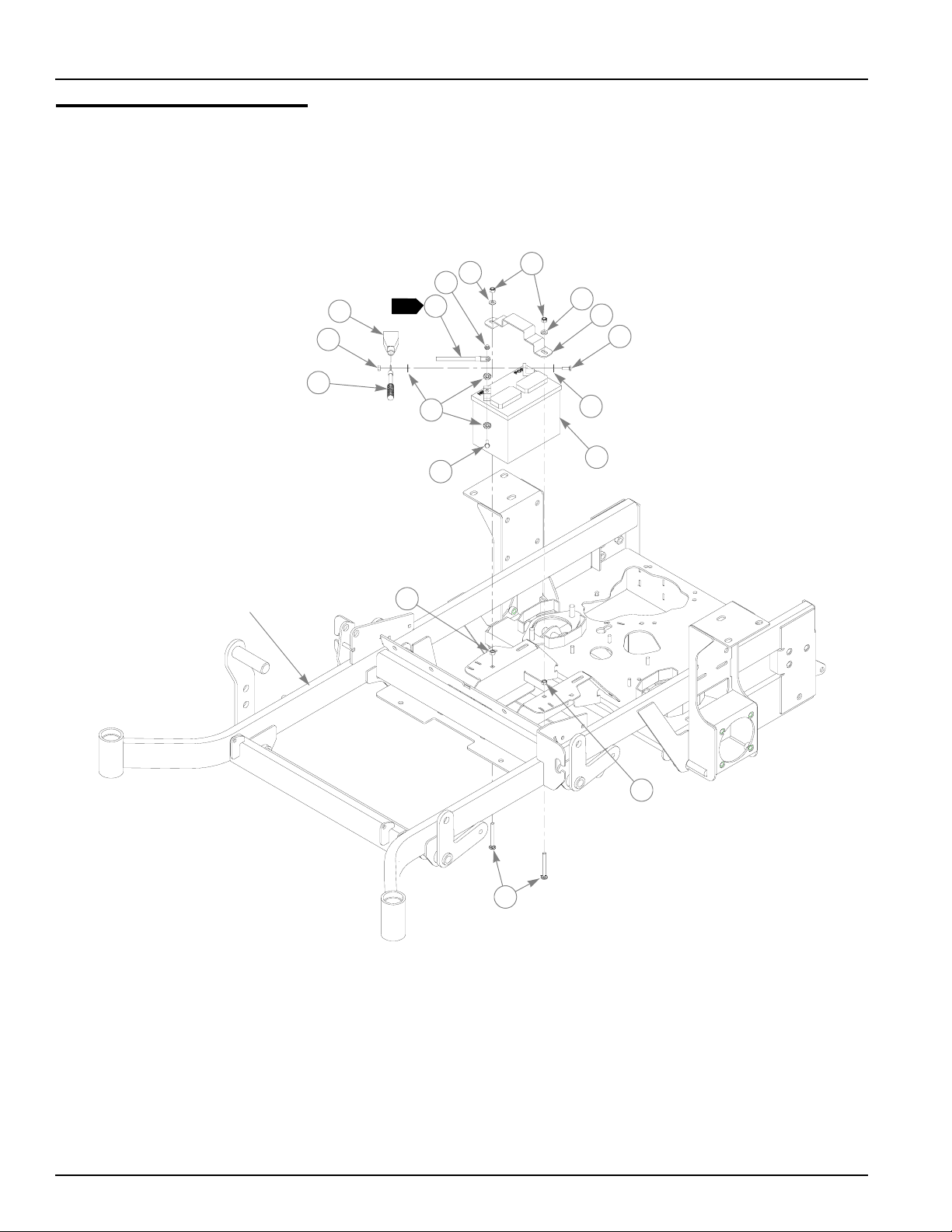
Battery Installation
TRACTOR
FRAME
5
1
1
2
1
4
3
9
8
11
6
5
7
8
9
10
11
12
4-2 106575 7/06
Page 21

Battery Installation
ITEM
NO.
10 740696 740696 1 BATTERY
11 034272 034272 2 NT .312-18 HX G5 ZN
12 779850 779850 2 CB .312-18 X 3.00 FUL ZN
SERVICE
PART NO.
1 024927 024927 2 NT .250-20 HX GR 5 ZN
2 771428 771428 1 RED BATTERY CABLE BOOT
3 796219 796219 1 36" NEGATIVE BATTERY CABLE
4 744276 744276 1 POSITIVE BATTERY CABLE
5 768523 768523 2 FW .343 X .687 X .051/.080 HD ZNYC
6 058776 058776 2 NT .312-18 HX NL ZN
7 348417 348417 1 BATTERY CLAMP STRAP
8 055939 055939 2 CS .250-20 X .750 HX G5 ZN
9 029868 029868 4 LW .250 INT-EXT TOOTH ZN
MFG.
PART NO.
QTY DESCRIPTION
NOTES:
1. When performing service on mower, disconnect battery ground cable
and do not reconnect to battery until engine is ready to be started. See
Owners Manual.
106575 7/06 4-3
Page 22
Deck Lift Assembly
1
2
4
5
6
6
TRACTOR
FRAME
4
8
3
4
5
5
10
1
7
5
13
7
4
14
11
12
1
5
4
5
4
1
8
4
1
7
9
4
7
8
9
4-4 106575 7/06
Page 23

Deck Lift Assembly
{
INDEX
NO.
1 348318 348318 1 STOP HANDLE
2 600437 600437 1 DECK HEIGHT W/A 1/2" PIN
2
3 783001 783001 1 DECK LIFT INDICATOR
4 704643 704643 8 NT .437-14 HX FLG ZN
5 781294 781294 7 CLIP E, 1.00 X.625X .050
6 782995 782995 2 DECK LIFT SPRING ASSEMBLY
7 015495 015495 4 STRAIGHT GREASE FITTING
8 055749 055749 3 CS .437-14X1.750 HX G5 ZNYC
9 348391 018846 4 DECK LIFT CHAIN (5 LINKS)
10 756270 756270 1 CS .312-18 X 1.50 FLTHR GR5 ZNYC
11 034272 034272 1 NT .312-18 HX G5 ZNYC
12 348458 348458 1 DECK LEVELER YOKE W/A
13 781229 781229 1 CE .750X2.25 X1.75 HEADLESS
14 781831 781831 1 CS .437-14 X 1.750 FULTH G5 ZNYC
SERVICE
PART NO.
348284 N/A 1 HEIGHT ADJUSTMENT STOP 3/8"
MFG.
PART NO.
QTY DESCRIPTION
NOTES:
1. Apply grease to zerks (see owners manual).
2. Verify pin diameter prior to ordering replacement part. For mowers with
3/8" diameter pins, order 348284; for mowers with 1/2" pins, order
600437. For replacement purposes, item 3 comes with item 2 (600437).
106575 7/06 4-5
Page 24
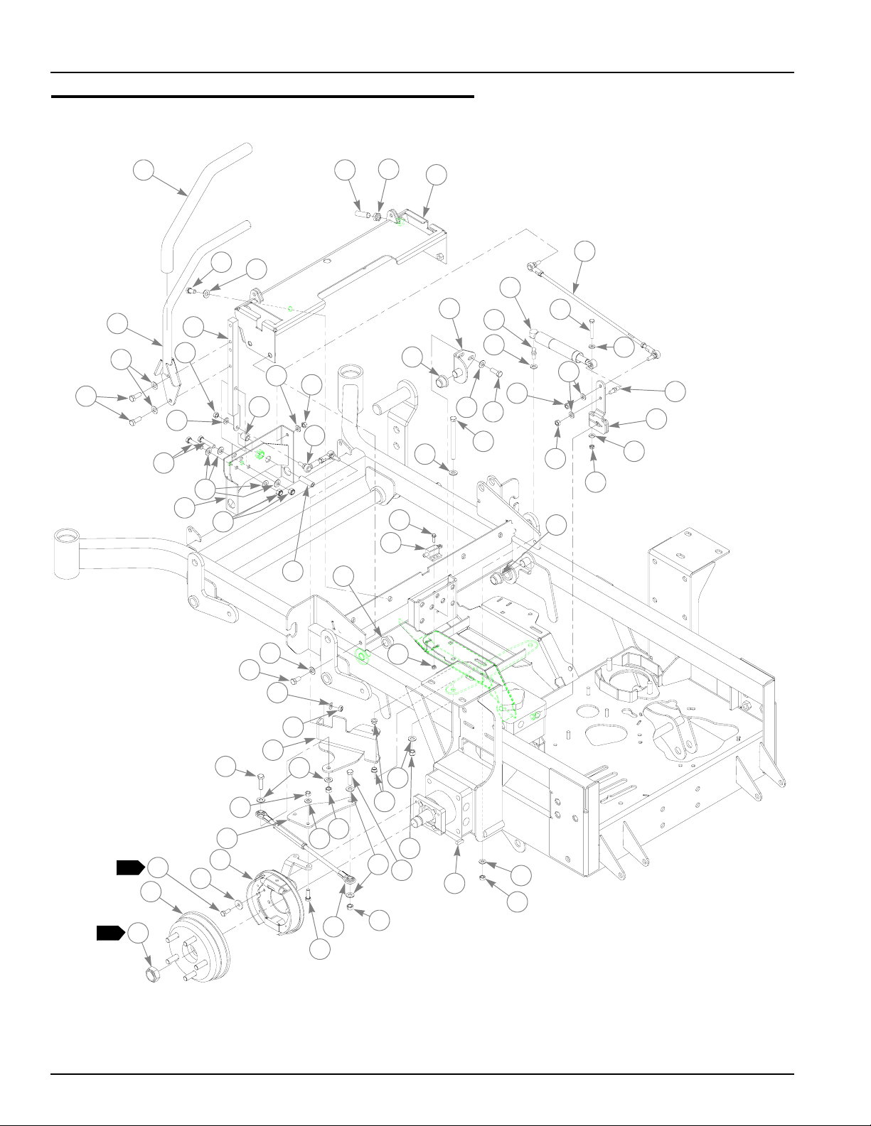
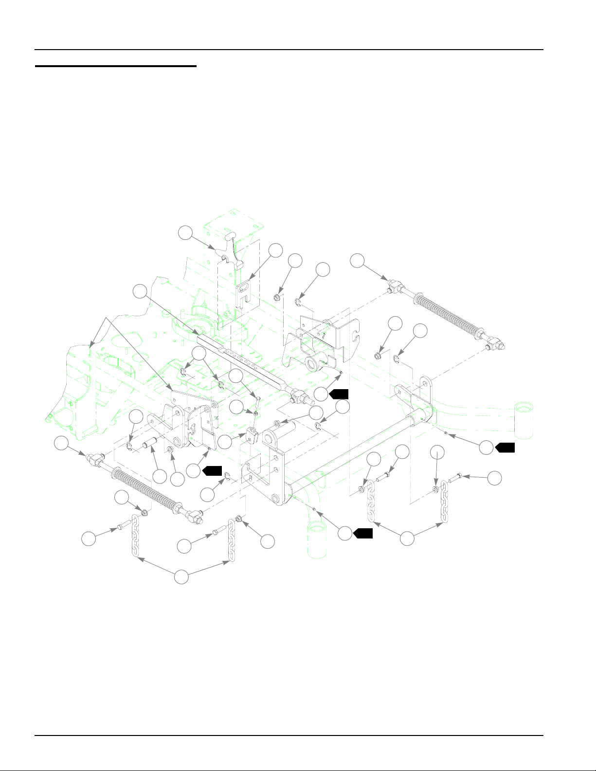
Steering and Park Brake Assembly
1
5
3
2
3
4
9
10
11
12
11
13
3
14
15
6
6
10
16
27
7
29
28
27
8
17
18
26
3
19
11
3
10
4
25
20
24
27
21
11
19
22
21
23
3
5
11
10
31
34
24
37
2
41
42
1
43
39
40
3
33
11
36
38
3
33
32
30
3
34
15
35
11
24
4-6 106575 7/06
Page 25

Steering and Park Brake Assembly
ITEM
NO.
1 781260 N/A 2 STEERING BAR GRIP
2 348755 348755 2 STEERING BAR
5
3 767954 767954 43 FW .406 X .812 X .060 SAE HD ZN
4 036244 036244 10 CS .375-16 X 1.000 HX G5 ZN
5 055822 055822 8 CS .375-16 X .750 HX G5 ZN
6 781716 781716 4 SS .500-13 X 1.75 SH ZN
7 053199 053199 2 NT .500-13 HX JAM ZN
8 348987 348987 1 STEERING CONTROL PANEL
9 348946 348946 2 STEERING ARM MOUNT
10 041152 041152 8 NT .312-24 HX ZN
11 768523 768523 14 FW .34 3X .687 X .051/.080 HD ZN/YL
12 348862 348862 4 STEERLEVER BUSHING
13 705178 705178 6 CS .375-16 X 1.750 HX G5 ZN
14 348888 348888 1 STEERLEVER SUPPORT LH
15 086660 086660 8 NT .375-16 HX LK NY
16 781583 781583 2 BRAKE ROD ASSEMBLY
17 781286 781286 2 PUMP ROD ADJUSTER ASSEMBLY
18 783696 783696 2 CENTERING DAMPENER
19 781922 781922 4 DAMPENER BALL STUD
20 704163 704163 2 CS .250-20 X 2.00 HX G5 ZN
21 768515 768515 4 FW .281 X .625 X .051/.080 HD ZN/YL
22 347684 347684 2 SUPER Z PUMP ARM
23 068551 068551 2 NT .250-20 HX NL ZN
24 034272 034272 8 NT .312-18 HX G5 ZN
25 782979 782979 2 CS .375-16 X 4.75 HX G5 ZN
26 348797 348797 2 ADJUSTABLE PIVOT
27 781153 781153 4 BUSHING
28 063198 063198 4 CS 10-24 X .750 HXFLK ZN
29 781211 781211 2 PUSH BUTTON SWITCH
30 059832 059832 4 NT #10-24 HX NL ZN
31 350330 350330 1 L.S. BRAKE PIVOT ARM
32 765339 765339 4 BUSHING
33 054502 054502 4 NT .375-16 HX GRD 5 ZN
34 005116 005116 4 CS .375-16 X 1.375 HX G5 ZN
35 783852 N/A 2 KEY FOR WHITE MOTOR
36 350397 350397 2 BRAKE LINK TURNBUCKLE
37 354035 354035 2 WHITE BRAKE LEVER EXTENSION
38 036236 036236 4 CS .312-18 X 1.000 HX G5 ZN
39 783126 783126 1 LH WHITE BRAKE ASSY
3
4
40 712927 712927 8 FW .344 X 1.00 X .12 HRD ZNYC
41 048876 048876 8 CS .312-18 X .750 HX G8 ZNYC
42 782953 782953 2 WHITE HUB ASSEMBLY
43 783845 N/A 2 NUT FOR WHITE MOTOR
SERVICE
PART NO.
348714 348714 1 STEERLEVER SUPPORT RH
350264 350264 1 R.S. BRAKE PIVOT ARM
783118 783118 1 RH WHITE BRAKE ASSY
MFG.
PART NO.
QTY DESCRIPTION
106575 7/06 4-7
Page 26

NOTES:
1. Torque to 280-310 ft.-lbs. Included with wheel motor.
2. Torque to 24 ft.-lbs.
3. 783126 used on left wheel.
4. 783118 used on right wheel.
5. Includes Item 1 (781260 Steering Bar Grip).
4-8 106575 7/06
Page 27

This page intentionally left blank.
106575 7/06 4-9
Page 28
Pump
Belt and Pulleys Installation
TRACTOR
FRAME
7
24
25
26
2
6
2
6
8
1
5
2
3
4
1
5
18
19
20
9
13
15
8
2
6
23
3
10
12
10
14
16
17
7
10
11
10
4
22
21
4-10 106575 7/06
Page 29

Pump Belt and Pulleys Installation
INDEX
NO.
1 783761 783761 1 SUPER Z SINGLE ENGINE PULLEY
2 212076 212076 1 KEY 1/4 SQ X 1.50 LONG
3 787366 787366 1 WARNER CLUTCH
4 783829 783829 1 FW .460 X 1.750 X .250 ZNYC (AIR COOLED ENGINES ONLY)
5 785659 785659 1 CS .437-20 X 2.50 HX G5 ZNYC (AIR COOLED ENGINES ONLY)
6 083196 083196 4 SS .312-18X .750 SQ-HD ZN
7 782466 782466 2 PULLEY & FAN FOR BDP-21
8 783712 783712 2 KEY FOR BDP21L
9 008193 008193 2 NT .500-13 HX G5 ZNYC
10 767962 767962 4 FW .531 X 1.063 X .090 SAE HD ZN
11 016527 016527 2 CS .500-13 X 1.00 HX G5 ZNYC
12 366765 366765 1 CLUTCH ANCHOR ANGLE
13 784918 784918 2 RUBBER BUMPER
14 349761 349761 1 PUMP IDLER ARM
15 015495 015495 1 STRAIGHT GREASE FITTING
16 025296 025296 1 FW .760 X 1.625 X .08 ZN
17 061101 061101 1 NT .750-10 HX NL ZN
18 781856 781856 1 IDLER PULLEY
19 028118 028118 1 FW .62 X 1.00 X.134 ZN
20 794446 794446 1 CS .625-11 X 1.50 HX G5 ZN
21 781302 781302 1 IDLER SPRING
22 781443 781443 1 A-SEC PUMP IDLER BELT
23 791251 791251 1 CLUTCH PIGTAIL HARNESS WITH DIODE
24 036236 036236 1 CS .312-18 X 1.00 HX G5 ZNYC
25 768523 768523 1 FW .343 X .687 X .051/.080 HD ZNYC
26 034272 034272 1 NT .312-18 HX G5 ZNYC
SERVICE
PART NO.
712893 712893 1 FW .406X 1.25X.12 HRD ZN (26 HP KAWASAKI ONLY)
797142 797142 1 CS M10-1.5X 65 HX ZY G8.8 (26 HP KAWASAKI ONLY)
MFG.
PART NO.
QTY DESCRIPTION
NOTES:
1. Torque to 45-48 ft-lbs.
2. Torque to 12-15 ft-lbs
3. Apply grease at zerk (see owners manual).
4. Do not torque Item 17 (NT .750-10 HX NL ZN), Item 14 (349761 Pump
Idler Arm) should pivot freely.
5. Included with Honda 24 HP engine (785014).
6. Electric clutch burnishing procedure: After installing a new clutch it is
important to burnish the clutch to insure maximum deck clutch life. In an
open area with no bystanders set the engine speed to half throttle.
Cycle the deck clutch on for 15 seconds, and then off for 15 seconds.
Repeat this operation 10 times, it will require about 5 minutes to
complete.
106575 7/06 4-11
Page 30

4-12 106575 7/06
Page 31

Chapter 5 Contents
Kawasaki 25 HP Engine Installation . . . . . . . . . . . . . . . . . . . . . . . . . 5-2
Kawasaki 26 HP Engine Installation . . . . . . . . . . . . . . . . . . . . . . . . . 5-6
Kawasaki 26 HP Engine Installation . . . . . . . . . . . . . . . . . . . . . . . . 5-10
Honda 24 HP Engine Installation. . . . . . . . . . . . . . . . . . . . . . . . . . . 5-14
Kohler 27 & 30 HP Engine Installation. . . . . . . . . . . . . . . . . . . . . . . 5-18
Kohler 28 HP EFI Engine Installation . . . . . . . . . . . . . . . . . . . . . . . 5-22
Kohler 28 HP EFI Engine Installation . . . . . . . . . . . . . . . . . . . . . . . 5-26
Fuel System–Air Cooled W/Carburetor . . . . . . . . . . . . . . . . . . . . . . 5-30
Fuel System Installation–Liquid Cooled. . . . . . . . . . . . . . . . . . . . . . 5-32
Fuel System Installation–With EFI. . . . . . . . . . . . . . . . . . . . . . . . . . 5-34
Fuel System Installation–With EFI. . . . . . . . . . . . . . . . . . . . . . . . . . 5-36
Instrument Panel Assembly–Air Cooled W/Carb . . . . . . . . . . . . . . . 5-38
Instrument Panel Assembly–Liquid Cooled . . . . . . . . . . . . . . . . . . . 5-40
Instrument Panel Assembly–Liquid Cooled . . . . . . . . . . . . . . . . . . . 5-42
Instrument Panel Assembly–With EFI . . . . . . . . . . . . . . . . . . . . . . . 5-44
Instrument Panel Assembly–With EFI . . . . . . . . . . . . . . . . . . . . . . . 5-46
Electrical Schematic–Common Air Cooled(799320) . . . . . . . . . . . . 5-48
Electrical Schematic–Kawasaki LC (796599) . . . . . . . . . . . . . . . . . 5-49
Electrical Schematic–Kawasaki LC (799338) . . . . . . . . . . . . . . . . . 5-50
Electrical Schematic–Kohler EFI (789560) . . . . . . . . . . . . . . . . . . . 5-51
Electrical Schematic–Kohler EFI (799346) . . . . . . . . . . . . . . . . . . . 5-52
106575 7/06 5-1
Page 32

Kawasaki 25 HP Engine Installation
2
2
TAN/ R ED
TO ENGINE
SENSOR,
YELLOW
RED/BLK
5
6
12
6
13
14
PURPLE
POSITIVE
BATTERY
CABLE
2
5
2
10
11
2
BLK
5
6
7
TO SPADE
TERMINAL
5
6
TRACTOR
FRAME
HOUR METER
CONNECTION
9
1
TO BULLET
TERMINALS
4
8
2
3
15
2
2
3
8
NEGATIVE
BATTERY
CABLE
19
18
24
6
25
26
9
A
3
17
29
17
16
21
17
6
20
21
3
22
3
23
24
6
28
A
27
HOOD
3
45
2
3
30
23
3
31
44
39
38
43
42
3
32
33
3
37
15
40
36
35
3
34
41
1
5-2 106575 7/06
Page 33

Kawasaki 25 HP Engine Installation
ITEM
NO.
1 782318 N/A 1 KAWASAKI 25 HP 3600RPM ENGINE
2 058776 058776 4 NT .312-18 HX ZYNL
3 768523 768523 24 FW .343 X .687 X .051/.080 HD ZN/YL
4 029876 029876 1 LW .312 INT-EXT TOOTH ZN
5 024927 024927 3 NT .250-20 HX GR.5 ZN
6 768515 768515 11 FW .281 X .625 X .051/.080 HD ZN/YL
7 792762 792762 1 BATTERY CABLE
8 799312 799312 1 KAW (23 & 25 HP) WIRE HARNESS ADAPTER
9 799320 799320 1 XR7 COMMON WIRE HARNESS
10 044255 044255 1 NT #10-32 HX ZN
11 771428 771428 1 RED BATTERY CABLE BOOT
12 030817 030817 1 STARTER SOLENOID
13 055947 055947 2 CS .250-20 X .500 HX G5 ZN
14 792192 792192 1 STARTER RELAY GROUND WIRE
15 050161 050161 4 CS .312-18 X 1.75 HX G5 ZN
16 786673 786673 1 DONALDSON AIR CLEANER CAP
17 057661 057661 HOSE CLAMP
18 782763 782763 1 AIR CLEANER
19 788943 788943 1 AIR FILTER INDICATOR
20 785741 785741 1 MOUNTING BAND
21 034272 034272 7 NT .312-18 HX G5 ZN
22 357780 357780 1 SUPER Z HOOD SCOOP
23 036236 036236 3 CS .312-18 X 1.00 HX G5 ZNYC
24 055939 055939 6 CS .250-20 X .75 HX G5 ZNYC
25 783837 783837 1 ELECTRIC COOLER FAN
26 044818 044818 4 CN ZN TIN-C7343-1420
27 356121 356121 1 SUPER Z HOOD
28 778738 778738 1 .312 WIRING CLAMP
29 786038 786038 1 REMOTE AIR FILTER HOSE
30 796524 796524 1 M20X2.5 OIL DRAIN VALVE
31 034280 034280 4 CS .312-18 X .750 HX G5 ZNYC
32 350371 350371 1 MUFFLER GUARD
33 380618 380618 1 SUPER Z ENGINE GUARD
34 064006 064006 2 CS .312-18 X .625 HX G5 ZN
35 767962 767962 6 FW .531 X 1.063 X .090 SAE HD ZN
36 016527 016527 6 CS .500-13 X 1.00 HX G5 ZN
37 780841 780841 2 KAW (23) MUFFLER GASKET
38 781732 781732 1 MUFFLER MANIFOLD
39 360693 360693 1 HEAT SHIELD
40 017004 017004 4 LW .312 MED SPRING ZN
41 782664 782664 4 NT M8-1.25 HX STAINLESS STEEL
42 782649 782649 1 KAW (23) EXHAUST PIPE CLAMP
1
43 720177 720177 2 CS M 8-1.25 X 20 10.9 HXFL ZN
44 781724 781724 1 MUFFLER
45 047654 047654 2 CLIP
SERVICE
PART NO.
MFG.
PART NO.
QTY DESCRIPTION
106575 7/06 5-3
Page 34

NOTES:
1. Includes mounting hardware.
2. Part of Item 9 (799312 Super Z Tractor Wire Harness).
3. Engine oil capacity; 2 US quarts.
4. Engine RPM to be set at 3600±50.
5. Supplied with engine.
6. Includes one (1) of 057661 Hose Clamp.
7. When installing lower hose clamp on air cleaner hose, install as low as
possible (against carburetor inlet).
8. Ground wires from main wire harness (799320) and starter solenoid
(item 11–030817).
9. Wires from main wire harness (799320).
10. Air filter service parts:
785261 MAIN AIR FILTER ELEMENT
763318 VACUATOR VALVE
5-4 106575 7/06
Page 35

This page intentionally left blank.
106575 7/06 5-5
Page 36

Kawasaki 26 HP Engine 6Installation
1
11
13
12
11
2
TAN/ R ED
BLK
2
13
2
1
7
10
8
3
4
5
6
8
9
17
18
19
20
PART OF
ENGINE
23
25
11
14
16
20
HOUR METER
CONNECTION
15
KAWASAKI
ENGINE
SCREEN
19
20
21
24
22
22
26
NEGATIVE
BATTERY
CABLE
29
35
32
33
34
POSITIVE
BATTERY
CABLE
2
13
27
28
31
29
30
9
8
5-6 106575 7/06
Page 37

Kawasaki 26 HP Engine Installation
6
ITEM
NO.
1 795617 795617 1 KAWASAKI FD731V ENGINE
2 796748 796748 1 KAWASAKI 26HP EXHAUST MANIFOLD
3 780841 780841 2 KAW (23) MUFFLER GASKET
4 017004 017004 4 LW .312 MED SPRING ZN
5 782664 782664 4 NT M8-1.25 HX STAINLESS STEEL
6 796755 796755 1 KAWASAKI 26HP LC MUFFLER
7 785378 785378 1 1.50" MUFFLER CLAMP
8 767962 767962 14 FW .531 X 1.063 X .090 SAE HD ZN
9 016527 016527 10 CS .500-13 X 1.00 HX G5 ZN
10 008193 008193 4 NT .500-13 HX G5 ZNYC
11 055939 055939 9 CS .250-20 X .75 HX G5 ZNYC
12 357780 357780 1 SUPER Z HOOD SCOOP
13 768515 768515 9 FW .281 X .625 X .051/.080 HD ZN/YL
14 783837 783837 1 ELECTRIC COOLER FAN
15 348672 348672 1 KAWASAKI LC 26HP HOOD
16 044818 044818 4 CN ZN TIN-C7343-1420
17 036236 036236 4 CS .312-18 X 1.00 HX G5 ZNYC
18 768523 768523 4 FW .343 X .687 X .051/.080 HD ZN/YL
19 024927 024927 2 NT .250-20 HX GR. 5 ZNYC
20 073866 073866 4 FW .281 X .500 X .06 ZNYC
21 104133 104133 1 SCREEN SUPPORT
22 064329 064329 2 CS .250-20 X .625 HX G5
23 030437 030437 2 MS #10-24 X .375 RD SL
24 035626 035626 2 NT #10-24 HX ZN
25 010470 010470 1 OVER CENTER LATCH ZINC
26 796524 796524 1 M20 X 2.5 OIL DRAIN VALVE
27 100800 100800 1 ENGINE AIR DEFLECTOR
28 769166 769166 1 HOUR METER
29 029876 029876 5 LW .312 INT-EXT TOOTH ZN
30 028035 028035 4 CS M 8-1.25 X 20 HX G8.8
31 100495 100495 1 SUPER Z ENGINE GUARD
32 017079 017079 1 FW .250 X .560 X .04 SAE Z
33 077545 N/A 1 NT M8-1.25-10-HX ZNYC
34 796599 N/A 1 26HP KAWASAKI WIRE HARNESS
35 720516 720516 1 CS M8 X1.25 X 16 G10.9 HX
SERVICE
PART NO.
MFG.
PART NO.
QTY DESCRIPTION
NOTES:
1. Includes mounting hardware.
2. Part of Item 24 (796599 Tractor Wire Harness).
3. Engine oil capacity, 2.4 US quarts (including filter).
4. Engine coolant capacity, 2.9 US quarts.
5. Engine RPM to be set at 3600±50.
6. Used on mowers with serial number prior to 0506000.
106575 7/06 5-7
Page 38

7. Air filter service parts (see engine manual other engine service parts):
785261 MAIN AIR FILTER ELEMENT
785279 SAFETY AIR FILTER ELEMENT
5-8 106575 7/06
Page 39

This page intentionally left blank.
106575 7/06 5-9
Page 40

Kawasaki 26 HP Engine 6Installation
18
17
11
13
1
2
3
4
5
6
2
BLK
2
11
TAN/ R ED
13
14
A
HOUR METER
CONNECTION
15
12
A
10
1
7
8
8
9
PART OF
ENGINE
11
13
19
20
23
27
29
16
KAWASAKI
ENGINE
SCREEN
19
20
21
24
25
22
26
22
20
28
HOOD
NEGATIVE
BATTERY
CABLE
31
36
POSITIVE
BATTERY
CABLE
33
34
2
35
45
32
18
31
9
5-10 106575 7/06
8
Page 41

Kawasaki 26 HP Engine Installation
6
ITEM
NO.
1 795617 795617 1 KAWASAKI FD731V ENGINE
2 796748 796748 1 KAWASAKI 26HP EXHAUST MANIFOLD
3 780841 780841 2 KAW (23) MUFFLER GASKET
4 017004 017004 4 LW .312 MED SPRING ZN
5 782664 782664 4 NT M8-1.25 HX STAINLESS STEEL
6 796755 796755 1 KAWASAKI 26HP LC MUFFLER
7 785378 785378 1 1.50" MUFFLER CLAMP
8 767962 767962 14 FW .531 X 1.063 X .090 SAE HD ZN
9 016527 016527 10 CS .500-13 X 1.00 HX G5 ZN
10 008193 008193 4 NT .500-13 HX G5 ZNYC
11 055939 055939 9 CS .250-20 X .75 HX G5 ZNYC
12 357780 357780 1 SUPER Z HOOD SCOOP
13 768515 768515 9 FW .281 X .625 X .051/.080 HD ZN/YL
14 783837 783837 1 ELECTRIC COOLER FAN
15 348672 348672 1 KAWASAKI LC 26HP HOOD
16 044818 044818 4 CN ZN TIN-C7343-1420
17 036236 036236 4 CS .312-18 X 1.00 HX G5 ZNYC
18 768523 768523 8 FW .343 X .687 X .051/.080 HD ZN/YL
19 024927 024927 2 NT .250-20 HX GR. 5 ZNYC
20 073866 073866 4 FW .281 X .500 X .06 ZNYC
21 104133 104133 1 SCREEN SUPPORT
22 064329 064329 2 CS .250-20 X .625 HX G5
23 030437 030437 2 MS #10-24 X .375 RD SL
24 035626 035626 2 NT #10-24 HX ZN
25 010470 010470 1 OVER CENTER LATCH ZINC
26 033035 033035 2 .12 X .75 WEATHERSTRIP (
27 033035 033035 2 .12 X .75 WEATHERSTRIP
28 796524 796524 1 M20 X 2.5 OIL DRAIN VALVE
29 100800 100800 1 ENGINE AIR DEFLECTOR
30 029876 029876 1 LW .312 INT-EXT TOOTH ZN
31 028035 028035 4 CS M 8-1.25 X 20 HX G8.8
32 100495 100495 1 SUPER Z ENGINE GUARD
33 017079 017079 1 FW .250 X .560 X .04 SAE Z
34 077545 N/A 1 NT M8-1.25-10-HX ZNYC
35 799338 799338 1 26HP KAWASAKI WIRE HARNESS
36 720516 720516 1 CS M8 X1.25 X 16 G10.9 HX
37 047654 047654 2 CLIP
SERVICE
PART NO.
MFG.
PART NO.
QTY DESCRIPTION
NOTES:
1. Includes mounting hardware.
2. Part of Item 24 (799338 Tractor Wire Harness).
3. Engine oil capacity, 2.4 US quarts (including filter).
4. Engine coolant capacity, 2.9 US quarts.
5. Engine RPM to be set at 3600±50.
6. Used on mowers with serial numbers 05060000 and higher.
106575 7/06 5-11
Page 42

7. Air filter service parts (see engine manual other engine service parts):
785261 MAIN AIR FILTER ELEMENT
785279 SAFETY AIR FILTER ELEMENT
5-12 106575 7/06
Page 43

This page intentionally left blank.
106575 7/06 5-13
Page 44

Honda 24 HP Engine Installation
2
TAN/RE D
BLK
2
HOOD
1
HOUR METER
2
3
CONNECTION
5
16
18
42
14
17
8
7
6
1
4
6
6
5
23
10
21
22
15
24
23
11
12
10
13
9
25
A
26
15
10
30
YEL
40
15
3
6
NEGATIVE
BATTERY
CABLE
POSITIVE
BATTERY
CABLE
3
ORG
BRN
41
3
28
GRA
PUR
6
3
2
27
14
15
15
32
6
39
6
A
17
3
RED/BLK
31
17
30
15
24
19
15
15
33
29
20
15
38
34
15
33
37
15
36
35
24
5-14 106575 7/06
Page 45

Honda 24 HP Engine Installation
ITEM
NO.
1 785014 785014 1 HONDA 24HP ENGINE
2 784843 784843 1 MUFFLER
3 720177 720177 2 CS M 8-1.25 X 20 10.9 HXFL ZN
4 785378 785378 1 1.50" MUFFLER CLAMP
1
5 782664 N/A 4 NT M8-1.25 HX STAINLESS STEEL
6 017004 N/A 4 LW .312 MED SPRING ZN
7 785543 N/A 2 HONDA (20) MUFFLER GASKET
8 784959 784959 1 MUFFLER MANIFOLD
9 056077 056077 2 CS .250-20 X 1.00 HX G5 ZNYC
10 768515 768515 8 FW .281 X .625 X .051/.080HD ZNYC
11 785477 N/A 1 HONDA 20 AMP RECTIFIER
12 017038 017038 2 LW .250 MED SPRING ZNYC
13 024927 024927 2 NT .250-20 HX GR.5 ZNYC
14 034272 034272 7 NT .312-18 HX G5 ZN
15 768523 768523 27 FW .343 X .687 X .051/.080 HD ZN/YL
16 775353 775353 1 ENGINE CENTRIFICAL PRECLEANER
17 057661 057661 2 HOSE CLAMP
18 785741 785741 1 MOUNTING BAND
19 787689 787689 1 HONDA OIL DRAIN VALVE
20 787713 787713 1 0.50" LOW PRESSURE HOSE, 3.00" LONG
21 782763 782763 1 AIR CLEANER
22 357780 357780 1 HOOD SCOOP
23 055939 055939 6 CS .250-20 X .750 HX G5 ZNYC
24 036236 036236 6 CS .312-18 X 1.00 HX G5 ZNYC
25 783837 783837 1 ELECTRIC COOLER FAN
26 044818 044818 4 CN ZN TIN-C7343-1420
27 356121 356121 1 SUPER Z HOOD
28 778738 778738 1 .312 WIRING CLAMP
29 034280 034280 4 CS .312-18X .750 HX G5 ZNYC
30 058776 058776 4 NT .312-18 HX ZYNL
31 785675 785675 1 REMOTE AIR FILTER HOSE
32 029876 029876 1 LW .312 INT-EXT TOOTH ZN
33 050161 050161 4 CS .312-18 X 1.75 HX G5 ZN
34 380691 380691 1 SUPER Z ENGINE GUARD
35 016527 016527 6 CS .500-13 X 1.00 HX G5 ZNYC
36 767962 767962 6 FW .531 X 1.063 X .090 SAE HD ZN
37 377994 377994 1 MMZ ROLLER HEAT SHIELD
38 382168 382168 1 MUFFLER GUARD
39 077545 N/A 1 NT M8-1.25 X 10 HX ZNYC
40 799320 799320 1 XR7 COMMON WIRE HARNESS
41 799304 799304 1 HONDA 24HP WIRE HARNESS ADAPTER
42 047654 047654 2 CLIP
SERVICE
PART NO.
MFG.
PART NO.
QTY DESCRIPTION
106575 7/06 5-15
Page 46

NOTES:
1. Includes mounting hardware.
2. Part of Item 40 (799320 XR7 Common Wire Harness).
3. Part of Item 41 (799304 Honda 24hp Wire Harness Adapter).
4. Engine oil capacity; 2 US quarts.
5. Engine RPM to be set at 3600± 50.
6. Includes one (1) of 057661 Hose Clamp.
7. Supplied with engine.
8. When installing lower hose clamp on air cleaner hose, install as low as
possible (against carburetor inlet).
9. Air filter service parts:
785261 MAIN AIR FILTER ELEMENT
763318 VACUATOR VALVE
5-16 106575 7/06
Page 47

This page intentionally left blank.
106575 7/06 5-17
Page 48

Kohler 27 & 30 HP Engine Installation
2
1
6
4
2
TAN/RED
1
2
5
BLK
5
8
11
12
9
35
6
3
33
10
36
6
13
26
NEGATIVE
BATTERY
CABLE
2
RED/BLK
2
6
PUR (P/O ENGINE)
RED
POSITIVE
BATTERY
CABLE
6
17
18
13
9
20
A
13
19
18
21
A
A
12
13
16
17
22
23
13
7
BLK
2
25
13
27
9
36
13
HOUR METER
CONNECTION
34
32
31
13
13
27
19
13
30
24
15
13
14
28
29
19
5-18 106575 7/06
Page 49

Kohler 27 & 30 HP Engine Installation
ITEM
NO.
1 788216 788216 1 KOHLER 27HP ENGINE CV740
2 788018 788018 1 MUFFLER
3 788026 788026 1 MUFFLER MANIFOLD
4 785378 785378 1 1.50" MUFFLER CLAMP
1
5 029751 029751 2 CS .375-16 X 1.00 HXFLK ZNYC
6 705137 705137 4 FW .391 X 1.250 X .060 ZNYC
7 016899 016899 2 NT .375-16 HXFLK ZNYC
8 786673 786673 1 DONALDSON AIR CLEANER CAP
9 057661 057661 2 HOSE CLAMP
10 782763 782763 1 AIR CLEANER
11 785741 785741 1 MOUNTING BAND
12 034272 034272 7 NT .312-18 HX G5 ZN
13 768523 768523 25 FW .343 X .687 X .051/.080 HD ZN/YL
14 796672 796672 1 3/8-18 OIL DRAIN VALVE
15 787713 787713 1 0.50" LOW PRESSURE HOSE
16 357780 357780 1 HOOD SCOOP
17 055939 055939 6 CS .250-20 X .750 HX G5 ZNYC
18 768515 768515 6 FW .281 X .625 X .051/.080 HD ZNYC
19 036236 036236 6 CS .312-18 X 1.00 HX G5 ZNYC
20 783837 783837 1 ELECTRIC COOLER FAN
21 044818 044818 4 CN ZN TIN-C7343-1420
22 356121 356121 1 SUPER Z HOOD
23 778738 778738 1 .312 WIRING CLAMP
24 034280 034280 4 CS .312-18X .750 HX G5 ZNYC
25 795310 795310 1 REMOTE AIR FILTER HOSE
26 029876 029876 1 LW .312 INT-EXT TOOTH ZN
27 050161 050161 4 CS .312-18 X 1.75 HX G5
28 382168 382168 1 MUFFLER GUARD
29 380691 380691 1 SUPER Z ENGINE GUARD
30 767962 767962 6 FW .531 X 1.063 X .090 SAE HD ZN
31 016527 016527 6 CS .500-13 X 1.00 HX G5 ZNYC
32 377994 377994 1 MMZ ROLLER HEAT SHIELD
33 799320 799320 1 COMMON AIR COOLED WIRE HARNESS
34 047654 047654 2 CLIP
35 788943 788943 1 AIR FILTER INDICATOR
36 058776 058776 4 NT .312-18 HX ZYNL
SERVICE
PART NO.
799296 799296 1 KOHLER 30 HP ENGINE CV750
MFG.
PART NO.
QTY DESCRIPTION
106575 7/06 5-19
Page 50

NOTES:
1. Includes mounting hardware.
2. Part of Item 33 (799320 Tractor Wire Harness).
3. Engine oil capacity; 2 US quarts.
4. 27 HP Engine RPM to be set at 3600± 50. 30 HP Engine RPM is set at
3600±50 RPM for high speed and 1800±100 RPM low speed
(Governed).
5. Includes one (1) of 057661 Hose Clamp.
6. Supplied with engine.
7. Air filter service parts:
785261 MAIN AIR FILTER ELEMENT
763318 VACUATOR VALVE
5-20 106575 7/06
Page 51

This page intentionally left blank.
106575 7/06 5-21
Page 52

Kohler 28 HP EFI Engine 7Installation
1
2
1
2
TAN/RED
3
6
12
43
5
15
9
10
16
6
7
44
13
11
17
4
5
6
14
21
22
23
20
17
24
25
28
A
29
30
7
22
17
31
17
21
27
8
BLK
2
13
16
26
25
A
45
45
17
35
NEGATIVE
BATTERY
CABLE
42
HOUR METER
34
17
CONNECTION
32
18
19
23
POSITIVE
BATTERY
CABLE
13
33
23
6
RED/BLK
2
17
37
17
38
36
17
17
36
41
40
39
23
5-22 106575 7/06
Page 53

Kohler 28 HP EFI Engine Installation
7
ITEM
NO.
1 788224 788224 1 KOHLER CV745 EFI ENGINE
2 789123 789123 1 MUFFLER
3 791442 N/A 1 KOHLER EFI OXYGEN SENSOR
4 788026 788026 1 MUFFLER MANIFOLD
5 785378 785378 1 1.50" MUFFLER CLAMP
1
6 029751 029751 2 CS .375-16 X 1.00 HXFLK ZNYC
7 705137 705137 4 FW .391 X 1.250 X .060 ZNYC
8 016899 016899 2 NT .375-16 HXFLK ZNYC
9 301986 301986 1 FUSE/RELAY MOUNT PLATE
10 042960 042960 1 CLIP CFV-0609
11 060731 060731 3 CS 10-24X .500 HXFLK ZNYC
12 786673 786673 1 DONALDSON AIR CLEANER CAP
13 057661 057661 2 HOSE CLAMP
14 782763 782763 1 AIR CLEANER
15 785741 785741 1 MOUNTING BAND
16 034272 034272 7 NT .312-18 HX G5 ZN
17 768523 768523 25 FW .343 X .687 X .051/.080 HD ZN/YL
18 796672 796672 1 3/8-18 OIL DRAIN VALVE
19 787713 787713 1 0.50" LOW PRESSURE HOSE
20 357780 357780 1 HOOD SCOOP
21 055939 055939 6 CS .250-20 X .750 HX G5 ZNYC
22 768515 768515 6 FW .281 X .625 X .051/.080 HD ZNYC
23 036236 036236 10 CS .312-18 X 1.00 HX G5 ZNYC
24 791434 791434 2 CS 10-24 X 2.00 HX G5 ZNYC
25 704932 704932 4 FW .219 X .500 X .048 ZNYC
26 059832 059832 2 NT #10-24 HX NL ZN
27 789602 N/A 1 KOHLER EFI ECU
28 783837 783837 1 ELECTRIC COOLER FAN
29 044818 044818 4 CN ZN TIN-C7343-1420
30 356121 356121 1 SUPER Z HOOD
31 778738 778738 1 .312 WIRING CLAMP
32 034280 034280 3 CS .312-18X .750 HX G5 ZNYC
33 769166 769166 1 HOUR METER
34 788034 788034 1 REMOTE AIR FILTER HOSE
35 029876 029876 1 LW .312 INT-EXT TOOTH ZN
36 050161 050161 4 CS .312-18 X 1.75 HX G5
37 382168 382168 1 MUFFLER GUARD
38 380691 380691 1 SUPER Z ENGINE GUARD
39 767962 767962 6 FW .531 X 1.063 X .090 SAE HD ZN
40 016527 016527 6 CS .500-13 X 1.00 HX G5 ZNYC
41 377994 377994 1 MMZ ROLLER HEAT SHIELD
42 789560 789560 1 SUPER Z KOHLER EFI WIRE HARNESS
43 047654 047654 2 CLIP
44 788943 788943 1 AIR FILTER INDICATOR
45 058776 058776 4 NT .312-18 HX ZYNL
SERVICE
PART NO.
MFG.
PART NO.
QTY DESCRIPTION
106575 7/06 5-23
Page 54

NOTES:
1. Includes mounting hardware.
2. Part of Item 42 (789560 Tractor Wire Harness).
3. Engine oil capacity; 2 US quarts.
4. Engine RPM to be set at 3600± 50.
5. Includes one (1) of 057661 Hose Clamp.
6. Supplied with engine.
7. Used on mowers with serial numbers prior to 05060000.
8. Air filter service parts:
785261 MAIN AIR FILTER ELEMENT
763318 VACUATOR VALVE
5-24 106575 7/06
Page 55

This page intentionally left blank.
106575 7/06 5-25
Page 56

Kohler 28 HP EFI Engine 7Installation
1
3
9
2
6
6
7
43
42
12
13
15
5
16
11
10
17
4
6
1
5
14
21
22
23
20
17
24
25
28
21
22
A
7
8
2
TAN/RED
BLK
29
30
2
13
16
17
31
17
25
27
A
26
45
44
17
34
NEGATIVE
BATTERY
CABLE
HOUR METER
CONNECTION
POSITIVE
33
13
17
18
BATTERY
CABLE
19
32
23
6
RED/BLK
2
17
41
36
37
17
35
17
23
35
17
40
38
39
5-26 106575 7/06
Page 57

Kohler 28 HP EFI Engine Installation
7
ITEM
NO.
1 788224 788224 1 KOHLER CV745 EFI ENGINE
2 789123 789123 1 MUFFLER
3 791442 N/A 1 KOHLER EFI OXYGEN SENSOR
4 788026 788026 1 MUFFLER MANIFOLD
5 785378 785378 1 1.50" MUFFLER CLAMP
1
6 029751 029751 2 CS .375-16 X 1.00 HXFLK ZNYC
7 705137 705137 4 FW .391 X 1.250 X .060 ZNYC
8 016899 016899 2 NT .375-16 HXFLK ZNYC
9 301986 301986 1 FUSE/RELAY MOUNT PLATE
10 042960 042960 1 CLIP CFV-0609
11 060731 060731 3 CS 10-24X .500 HXFLK ZNYC
12 786673 786673 1 DONALDSON AIR CLEANER CAP
13 057661 057661 2 HOSE CLAMP
14 782763 782763 1 AIR CLEANER
15 785741 785741 1 MOUNTING BAND
16 034272 034272 7 NT .312-18 HX G5 ZN
17 768523 768523 25 FW .343 X .687 X .051/.080 HD ZN/YL
18 796672 796672 1 3/8-18 OIL DRAIN VALVE
19 787713 787713 1 0.50" LOW PRESSURE HOSE
20 357780 357780 1 HOOD SCOOP
21 055939 055939 6 CS .250-20 X .750 HX G5 ZNYC
22 768515 768515 6 FW .281 X .625 X .051/.080 HD ZNYC
23 036236 036236 7 CS .312-18 X 1.00 HX G5 ZNYC
24 791434 791434 2 CS 10-24 X 2.00 HX G5 ZNYC
25 704932 704932 4 FW .219 X .500 X .048 ZNYC
26 059832 059832 2 NT #10-24 HX NL ZN
27 789602 N/A 1 KOHLER EFI ECU
28 783837 783837 1 ELECTRIC COOLER FAN
29 044818 044818 4 CN ZN TIN-C7343-1420
30 356121 356121 1 SUPER Z HOOD
31 778738 778738 1 .312 WIRING CLAMP
32 034280 034280 3 CS .312-18 X .750 HX G5
33 788034 788034 1 REMOTE AIR FILTER HOSE
34 029876 029876 1 LW .312 INT-EXT TOOTH ZN
35 050161 050161 4 CS .312-18 X 1.75 HX G5
36 382168 382168 1 MUFFLER GUARD
37 380691 380691 1 SUPER Z ENGINE GUARD
38 767962 767962 6 FW .531 X 1.063 X .090 SAE HD ZN
39 016527 016527 6 CS .500-13 X 1.00 HX G5 ZNYC
40 377994 377994 1 MMZ ROLLER HEAT SHIELD
41 799346 799346 1 SUPER Z KOHLER EFI WIRE HARNESS
42 047654 047654 2 CLIP
43 788943 788943 1 AIR FILTER INDICATOR
44 058776 058776 4 NT .312-18 HX ZYNL
SERVICE
PART NO.
MFG.
PART NO.
QTY DESCRIPTION
106575 7/06 5-27
Page 58

NOTES:
1. Includes mounting hardware.
2. Part of Item 42 (789560 Tractor Wire Harness).
3. Engine oil capacity; 2 US quarts.
4. Engine RPM to be set at 3600± 50.
5. Includes one (1) of 057661 Hose Clamp.
6. Supplied with engine.
7. Used on mowers with serial numbers 05060000 and higher.
8. Air filter service parts:
785261 MAIN AIR FILTER ELEMENT
763318 VACUATOR VALVE
5-28 106575 7/06
Page 59

This page intentionally left blank.
106575 7/06 5-29
Page 60

Fuel System2–Air Cooled W/Carburetor
1
6
1
7
1
3
13
11
9
4
2
13
5
8
15
13
10
8
5
14
6
7
1
16
17
7
5
16
13
14
15
12
6
7
1
5-30 106575 7/06
Page 61

Fuel System–Air Cooled W/Carburetor
2
ITEM
NO.
1 779306 779306 2 FUEL TANK CAP
2 793240 793240 1 LEFT SIDE FUEL TANK
3 793232 793232 1 RIGHT SIDE FUEL TANK
4 106732 N/A 1 REAR SEAT SUPPORT
5 767954 767954 3 FW .406 X .812 X .060 SAE HD ZN
6 712919 712919 11 FW .406 X 1.00 X .12 HRD ZN
7 055822 055822 12 CS .375-16 X .750 HX G5 ZN
8 036244 036244 2 CS .375-16 X 1.000 HX G5 ZN
9 045088 045088 1 HOSE CLAMP 1"
10 015818 015818 1 FUEL LINE 45.5” TOTAL
11 015818 015818 1 FUEL LINE 26.5” TOTAL
12 015818 015818 1 FUEL LINE 22.5” TOTAL (KAWASAKI)
13 000323 000323 6 CLIP
14 705954 705954 8 CS .500-13X1.25 HX G5 Z
15 767962 767962 8 FW .531 X 1.063 X .090 SAE HD ZN
16 797084 797084 1 3-WAY FUEL VALVE
17 347989 347989 1 FUEL SHUT-OFF BRACKET
SERVICE
PART NO.
015818 015818 1 FUEL LINE 36” TOTAL (HONDA)
015818 015818 1 FUEL LINE 38” TOTAL (KOHLER)
000331 000331 3 BLACK CABLE TIE (NOT SHOWN)
MFG.
PART NO.
QTY DESCRIPTION
NOTES:
1. Torque to 20 ft.-lbs.
2. Used on mowers with serial number 05042114 and higher.
3. Service parts for fuel tanks (not shown):
PART NO. DESCRIPTION
785295 FLANGE GROMMET
794107 1/4 ID, 3/8 OD, 1/16 WALL TUBING
794081 1/4 DIP TUBE WEIGHT FITTING
792986 1/4 X 1/4 ELBOW FITTING
106575 7/06 5-31
Page 62

Fuel System–Liquid Cooled
1
5
4
1
2
1
3
18
7
14
13
7
6
17
15
12
7
16
7
6
11
8
10
10
9
5
6
7
11
19
13
14
6
5
6
5
5-32 106575 7/06
Page 63

Fuel System–Liquid Cooled
ITEM
NO.
1 779306 779306 2 3.5" FUEL TANK CAP
2 793240 793240 1 LEFT SIDE Z FUEL TANK
3 793232 793232 1 RIGHT SIDE Z FUEL TANK
4 348615 N/A 1 REAR SEAT SUPPORT
5 055822 055822 12 CS .375-16 X .750 HX G5 ZN
6 767954 767954 14 FW .406 X .812 X .060 SAE HD ZN
7 000323 000323 8 CLIP
8 068478 068478 1 IN-LINE FUEL FILTER
9 797035 797035 1 1.75"DIA RUBBER COATED CLAMP
10 797084 797084 1 3-WAY NYLON FUEL VALVE
11 036244 036244 2 CS .375-16 X 1.00 HX G5 ZNYC
12 347989 347989 1 FUEL SHUT-OFF BRACKET
13 705954 705954 8 CS .500-13X1.25 HX G5 Z
14 767962 767962 8 FW .531 X 1.063 X .090 SAE HD ZN
15 015818 015818 1 FUEL LINE 6.00" LONG
16 015818 015818 1 FUEL LINE 26.75" LONG
17 015818 015818 1 FUEL LINE 45.38” LONG
18 015818 015818 1 FUEL LINE 29.00” LONG
19 045088 045088 1 HOSE CLAMP 1"
SERVICE
PART NO.
000331 000331 3 BLACK CABLE TIE (NOT SHOWN)
MFG.
PART NO.
QTY DESCRIPTION
NOTES:
1. Torque to 20 ft.-lbs.
2. Service parts for fuel tanks (not shown):
PART NO. DESCRIPTION
785295 FLANGE GROMMET
794107 1/4 ID, 3/8 OD, 1/16 WALL TUBING
794081 1/4 DIP TUBE WEIGHT FITTING
792986 1/4 X 1/4 ELBOW FITTING
106575 7/06 5-33
Page 64

Fuel System –With 2EFI
26
18
27
22
23
14
19
16
20
14
15
8
16
14
4
5
6
28
29
14
25
1
14
3
1
21
12
11
6
13
31
7
9
1
6
12
8
14
33
8
1
2
14
33
10
11
32
8
20
17
8
30
23
24
34
15
26
12
1
6
26
25
12
1
6
TRACTOR FRAME
WITH ENGINE
5-34 106575 7/06
Page 65

Fuel System–With EFI
2
ITEM
NO.
1 784181 784181 2 FUEL TANK CAP
2 794602 794602 1 LEFT SIDE SUPER Z FUEL TANK
3 794594 794594 1 RIGHT SIDE SUPER Z FUEL TANK
4 349944 N/A 1 REAR SEAT SUPPORT
5 767954 767954 14 FW .406 X .812 X .060 SAE HD ZN
6 055822 055822 14 CS .375-16 X .750 HX G5 ZN
7 789628 N/A 1 KOHLER EFI FUEL FILTER
8 791418 791418 6 5/16 CRIMP FUEL LINE CLAMP
9 791301 791301 1 CLAMP
10 036236 N/A 1 CS .312-18 X 1.00 HX G5 ZNYC
11 768523 N/A 2 FW .343X.687X.051/.080HD ZNYC
12 712919 712919 11 FW .406X 1.00X.12 HRD ZNYC
13 034272 N/A 1 NT .312-18 HX G5 ZN
14 000323 000323 10 CLIP
15 041491 041491 2 HOSE CLAMP
16 791269 791269 1 3-WAY DOUBLE FUEL VALVE
17 789636 N/A 1 KOHLER EFI FUEL REGULATOR
18 398370 398370 1 EFI FUEL MOUNT
19 024927 024927 2 NT .250-20 HX GR.5 ZNYC
20 768515 768515 4 FW .281 X .625 X .051/.080 HD ZNYC
21 055939 055939 2 CS .250-20 X .75 HX G5 ZNYC
22 714998 714998 4 MS #10-24 X .625 HX ZN
23 704932 704932 8 FW .219 X .500 X .048 ZNYC
24 059832 059832 4 NT #10-24 HX NL ZN
25 016527 016527 8 CS .500-13 X 1.00 HX G5 ZN
26 767962 767962 8 FW .531 X 1.063 X .090 SAE HD ZN
27 015818 015818 2 FUEL LINE 36.5”
28 015818 015818 1 FUEL LINE 8.25”
29 791400 791400 1 MULTI FUEL INJECTION FUEL LINE 13.0”
30 791400 791400 1 MULTI FUEL INJECTION FUEL LINE 36.5”
31 791400 791400 1 MULTI FUEL INJECTION FUEL LINE 21.5”
32 791400 791400 1 MULTI FUEL INJECTION FUEL LINE 18.0”
33 015818 015818 2 FUEL LINE 47.0”
34 789610 789610 1 KOHLER EFI FUEL PUMP
SERVICE
PART NO.
000331 000331 3 BLACK CABLE TIE (NOT SHOWN)
MFG.
PART NO.
QTY DESCRIPTION
NOTES:
1. Torque to 20 ft.-lbs.
2. Used with mowers with serial numbers prior to 05060000.
3. Service parts for fuel tanks (not shown):
PART NO. DESCRIPTION
785295 FLANGE GROMMET
794081 1/4 DIP TUBE WEIGHT FITTING
794735 FUEL RETURN ASSEMBLY
796607 FITTING, 1/4 HOSE BARB
106575 7/06 5-35
Page 66

Fuel System –With 2EFI
26
1
3
10
14
11
12
11
1
6
9
13
31
7
1
6
8
12
1
2
19
20
27
30
14
23
14
16
24
15
8
16
34
22
23
15
14
18
29
28
4
5
6
14
32
8
14
21
20
17
8
25
26
12
1
6
33
8
33
14
26
25
12
1
6
TRACTOR FRAME
WITH ENGINE
5-36 106575 7/06
Page 67

Fuel System–With EFI
2
ITEM
NO.
1 784181 784181 2 FUEL TANK CAP
2 796425 796425 1 LEFT SIDE SUPER Z FUEL TANK
3 796417 796417 1 RIGHT SIDE SUPER Z FUEL TANK
4 106732 106732 1 REAR SEAT SUPPORT
5 767954 767954 2 FW .406 X .812 X .060 SAE HD ZN
6 055822 055822 14 CS .375-16 X .750 HX G5 ZN
7 789628 N/A 1 KOHLER EFI FUEL FILTER
8 791418 791418 6 5/16 CRIMP FUEL LINE CLAMP
9 791301 791301 1 CLAMP
10 036236 N/A 1 CS .312-18 X 1.00 HX G5 ZNYC
11 768523 N/A 2 FW .343X.687X.051/.080HD ZNYC
12 712919 712919 12 FW .406X 1.00X.12 HRD ZNYC
13 034272 N/A 1 NT .312-18 HX G5 ZN
14 000323 000323 10 CLIP
15 041491 041491 2 HOSE CLAMP
16 791269 791269 1 3-WAY DOUBLE FUEL VALVE
17 789636 N/A 1 KOHLER EFI FUEL REGULATOR
18 398370 398370 1 EFI FUEL MOUNT
19 024927 024927 2 NT .250-20 HX GR.5 ZNYC
20 768515 768515 4 FW .281 X .625 X .051/.080 HD ZNYC
21 055939 055939 2 CS .250-20 X .75 HX G5 ZNYC
22 714998 714998 4 MS #10-24 X .625 HX ZN
23 704932 704932 8 FW .219 X .500 X .048 ZNYC
24 059832 059832 4 NT #10-24 HX NL ZN
25 705954 705954 8 CS .500-13X1.25 HX G5 Z
26 767962 767962 8 FW .531 X 1.063 X .090 SAE HD ZN
27 015818 015818 2 FUEL LINE 36.5”
28 015818 015818 1 FUEL LINE 8.25”
29 791400 791400 1 MULTI FUEL INJECTION FUEL LINE 13.0”
30 791400 791400 1 MULTI FUEL INJECTION FUEL LINE 36.5”
31 791400 791400 1 MULTI FUEL INJECTION FUEL LINE 21.5”
32 791400 791400 1 MULTI FUEL INJECTION FUEL LINE 18.0”
33 015818 015818 2 FUEL LINE 47.0”
34 789610 N/A 1 KOHLER EFI FUEL PUMP
SERVICE
PART NO.
000331 000331 3 BLACK CABLE TIE (NOT SHOWN)
MFG.
PART NO.
QTY DESCRIPTION
NOTES:
1. Torque to 20 ft.-lbs.
2. Used with mowers with serial numbers 05060000 and higher.
3. Service parts for fuel tanks (not shown):
PART NO. DESCRIPTION
785295 FLANGE GROMMET
794081 1/4 DIP TUBE WEIGHT FITTING
794735 FUEL RETURN ASSEMBLY
796607 FITTING, 1/4 HOSE BARB
106575 7/06 5-37
Page 68

Instrument Panel Assembly–Air Cooled W/Carb.
1
4
2
3
7
6
5
8
3
10
4
11
8
9
1
RIGHT SIDE
FUEL TANK
12
13
14
13
12
FUSE SIZE
AND LOCATION
15a
15a
10a
5-38 106575 7/06
Page 69

Instrument Panel Assembly–Air Cooled W/Carb
ITEM
NO.
1 776476 776476 1 PTO SWITCH
2 083022 N/A 2 IGNITION KEY
3 045898 045898 1 KEY SWITCH
4 785030 785030 1 Z CHOKE CABLE (KAWASAKI)
5 712257 712257 1 RED INDICATOR LIGHT
6 000430 000430 2 TIE STRAP
7 714998 714998 2 MS #10-24 X .625 HX ZN
8 704932 704932 4 FW .219 X .500 X .048 ZN
9 059832 059832 2 NT #10-24 HX NL ZN
10 769166 769166 1 HOUR METER
11 778365 778365 1 THROTTLE CABLE (ALL, EXCEPT FOR 30 HP KOHLER)
12 055947 055947 3 CS .250-20 X .500 HX G5 ZN
13 768515 768515 3 FW .281 X .625 X .051 /.080 HD ZN/YL
14 106633 106633 1 INSTRUMENT PANEL
SERVICE
PART NO.
785808 785808 1 INDAK COATED KEY
786657 786657 1 CHOKE CABLE (HONDA/KOHLER 27 CARB.)
786657 786657 1 CHOKE CABLE (KOHLER 30 CARB.)
787788 787788 1 THROTTLE CABLE (30 HP KOHLER, ONLY)
026237 N/A 6 RELAY (NOT SHOWN)
762195 N/A 1 DELAY MODULE (NOT SHOWN)
MFG.
PART NO.
QTY DESCRIPTION
1. Part of 799320 (Wire Harness)
NOTES:
106575 7/06 5-39
Page 70

Instrument Panel–Liquid 2Cooled
1
2
6
1
9
1
10
8
7
11
3
4
8
4
12
7
5
8
13
14
11
1
8
6
RIGHT SIDE
FUEL TANK
15
14
13
FUSE SIZE
AND LOCATION
15a
5-40 106575 7/06
20a
Page 71

Instrument Panel–Liquid Cooled
2
ITEM
NO.
1 785030 785030 1 CHOKE CABLE
2 776476 776476 1 PTO SWITCH
3 083022 N/A 2 IGNITION KEY
4 045898 045898 1 KEY SWITCH
5 712257 712257 3 RED INDICATOR LIGHT
6 059832 059832 6 NT #10-24 HX NL ZN
7 714998 714998 3 MS #10-24 X .625 HX ZN
8 704932 704932 6 FW .219 X .500 X .048 ZN
9 026237 N/A 3 RELAY
10 762195 N/A 1 DELAY MODULE
11 794347 794347 1 ULTRA LOUD WARBLE ALARM
12 787788 787788 1 THROTTLE CABLE
13 055947 055947 3 CS .250-20 X .500 HX G5 ZN
14 768515 768515 3 FW .281 X .625 X .051 /.080 HD ZN/YL
15 352716 352716 1 INSTRUMENT PANEL
SERVICE
PART NO.
785808 785808 1 INDAK COATED KEY
MFG.
PART NO.
1. Part of 796599 (Wire Harness)
QTY DESCRIPTION
NOTES:
2. Used on mowers with serial numbers prior to 05060000.
106575 7/06 5-41
Page 72

Instrument Panel–Liquid 2Cooled
1
2
3
4
4
9
11
5
6
7
12
13
9
10
1
7
8
RIGHT SIDE
FUEL TANK
14
13
12
FUSE SIZE
AND LOCATION
10a
5-42 106575 7/06
15a
Page 73

Instrument Panel–Liquid Cooled
2
ITEM
NO.
1 785030 785030 1 CHOKE CABLE
2 776476 776476 1 PTO SWITCH
3 083022 N/A 2 IGNITION KEY
4 045898 045898 1 KEY SWITCH
5 712257 712257 3 RED INDICATOR LIGHT
6 714998 714998 2 MS #10-24 X .625 HX ZN
7 704932 704932 4 FW .219 X .500 X .048 ZN
8 059832 059832 2 NT #10-24 HX NL ZN
9 794347 794347 1 ULTRA LOUD WARBLE ALARM
10 769166 769166 1 HOUR METER
11 787788 787788 1 THROTTLE CABLE
12 055947 055947 3 CS .250-20 X .500 HX G5 ZN
13 768515 768515 3 FW .281 X .625 X .051 /.080 HD ZN/YL
14 106633 106633 1 INSTRUMENT PANEL
SERVICE
PART NO.
785808 785808 1 INDAK COATED KEY
026237 N/A 6 RELAY (NOT SHOWN)
762195 N/A 1 DELAY MODULE (NOT SHOWN)
MFG.
PART NO.
QTY DESCRIPTION
NOTES:
1. Part of 796566 (Wire Harness)
2. Used on mowers with serial numbers 05060000 and higher.
106575 7/06 5-43
Page 74

Instrument Panel Assembly–2With EFI
1
2
4
1
5
3
7
3
1
6
9
10
8
7
1
7
8
7
4
11
12
13
15a
FUSE SIZE
AND LOCATION
20a
RIGHT SIDE
FUEL TANK
12
11
5-44 106575 7/06
Page 75

Instrument Panel Assembly–With EFI
2
ITEM
NO.
1 776476 776476 1 PTO SWITCH
2 083022 N/A 2 IGNITION KEY
3 045898 045898 1 KEY SWITCH
4 059832 059832 2 NT #10-24 HX NL ZN
5 026237 N/A 2 RELAY
6 762195 N/A 1 DELAY MODULE
7 704932 704932 6 FW .219 X .500 X .048 ZN
8 714998 714998 3 MS #10-24 X .625 HX ZN
9 787788 787788 1 THROTTLE CABLE
10 712257 712257 2 RED INDICATOR LIGHT
11 055947 055947 3 CS .250-20 X .500 HX G5 ZN
12 768515 768515 3 FW .281 X .625 X .051 /.080 HD ZN/YL
13 349608 349608 1 INSTRUMENT PANEL
SERVICE
PART NO.
785808 785808 1 INDAK COATED KEY
MFG.
PART NO.
QTY DESCRIPTION
NOTES:
1. Part of 789560 (Wire Harness).
2. Used on mowers with serial numbers prior to 0506000.
106575 7/06 5-45
Page 76

Instrument Panel Assembly–2With EFI
1
2
4
5
3
3
9
6
7
1
6
8
10
11
12
15a10a
FUSE SIZE
AND LOCATION
RIGHT SIDE
FUEL TANK
11
10
5-46 106575 7/06
Page 77

Instrument Panel Assembly–With EFI
2
ITEM
NO.
1 776476 776476 1 PTO SWITCH
2 083022 N/A 2 IGNITION KEY
3 045898 045898 1 KEY SWITCH
4 712257 712257 2 RED INDICATOR LIGHT
5 714998 714998 3 MS #10-24 X .625 HX ZN
6 704932 704932 6 FW .219 X .500 X .048 ZN
7 769166 769166 1 HOUR METER
8 059832 059832 2 NT #10-24 HX NL ZN
9 787788 787788 1 THROTTLE CABLE
10 055947 055947 3 CS .250-20 X .500 HX G5 ZN
11 768515 768515 3 FW .281 X .625 X .051 /.080 HD ZN/YL
12 106633 106633 1 INSTRUMENT PANEL
SERVICE
PART NO.
785808 785808 1 INDAK COATED KEY
026237 N/A 5 RELAY (NOT SHOWN)
762195 N/A 1 DELAY MODULE (NOT SHOWN)
MFG.
PART NO.
QTY DESCRIPTION
NOTES:
1. Part of 799346 (Wire Harness).
2. Used on mowers with serial numbers 0506000 and higher.
106575 7/06 5-47
Page 78

Electrical Schematic - Common Air Cooled (799320)
5-48 106575 7/06
Page 79

Electrical Schematic - 1Kawasaki LC (796599)
1. Used on mowers with serial numbers prior to 05060000.
106575 7/06 5-49
Page 80

Electrical Schematic - 1Kawasaki LC (799338)
1. Used on mowers with serial numbers 05060000 and higher.
5-50 106575 7/06
Page 81

Electrical Schematic - Kohler EFI 1(789560)
1. Used on mowers with serial numbers prior to 0506000.
106575 7/06 5-51
Page 82

Electrical Schematic - Kohler EFI 1(799346)
1. Used on mowers with serial numbers 05060000 and higher.
5-52 106575 7/06
Page 83

Chapter 6 Contents
Front Wheel Assembly. . . . . . . . . . . . . . . . . . . . . . . . . . . . . . . . . . . . 6-2
Front Wheel Breakdown–747782 . . . . . . . . . . . . . . . . . . . . . . . . . . . 6-4
Optional Semi-Pneumatic Tire/Wheel–789537 . . . . . . . . . . . . . . . . . 6-5
Drive Wheel Assembly. . . . . . . . . . . . . . . . . . . . . . . . . . . . . . . . . . . . 6-6
Anti-Rollover Wheel Assembly . . . . . . . . . . . . . . . . . . . . . . . . . . . . . 6-7
106575 7/06 6-1
Page 84

Front Wheel Assembly
1
2
3
4
3
5
6
3
5
TRACTOR
FRAME
1
2
3
3
10
4
3
5
6
5
7
8
10
9
7
8
9
10
1
12
10
2
11
12
1
6-2 106575 7/06
Page 85

Front Wheel Assembly
INDEX
NO.
1 705954 705954 2 CS .500-13 X 1.25 HX G5 ZN
2 344267 344267 2 FW .510 X 2.15 X .187 SPL ZN
3 798603 798603 2 FW .515 X 1.65 X .125 HD ZY
4 263517 263517 2 BEARING DISC
5 784223 784223 4 BEARING W/O COLLAR
6 387035 387035 2 SPACER, 1.07 X 1.312 X 2.793
7 045765 045765 2 FW 1.030 X 1.500 X.134 ZN
8 349266 349266 2 FORK
9 041475 041475 2 CS .750-10 X 9.50 HX ZN
10 025296 025296 4 FW .760 X 1.625 X .08 ZN
11 061101 061101 2 NT .750-10 HX NL ZN
12 747782 747782 2 WHEEL & TIRE ASSY
SERVICE
PART NO.
MFG.
PART NO.
QTY DESCRIPTION
NOTES:
1. Apply grease to zerks (see owners manual).
2. Torque to 100 ft.-lbs.
3. Assemble with extended inner race toward item 6 (387035 Spacer, 1.07
x 1.312 x 2.793).
106575 7/06 6-3
Page 86

Front Wheel Breakdown–747782
1
1
2
3
4
1
ITEM
NO.
1 039677 N/A 2
2 747741 N/A 1
3 747832 N/A 1
4 782771 N/A 1
5 019521 N/A 1
6 015511 N/A 1
SERVICE
PART NO.
1. Inflate tire to 8-10 psi.
MFG.
PART NO.
6
5
QTY DESCRIPTION
WHEEL BEARING
13 X 6.50 TIRE
6 X 4.5 WHEEL
BEARING SPACER
TIRE VALVE
GREASE FITTING 45 DEG 1/4
NOTES:
6-4 106575 7/06
Page 87

Optional Semi-Pneumatic Tire/Wheel–789537
1
2
3
4
1
ITEM
NO.
1 039677 N/A 2
2 789537 N/A 1
3 015511 N/A 1
4 782771 N/A 1
SERVICE
PART NO.
MFG.
PART NO.
QTY DESCRIPTION
WHEEL BEARING
TIRE/WHEEL ASSEMBLY
GREASE FITTING 45 DEG 1/4
BEARING SPACER
NOTES:
106575 7/06 6-5
Page 88

Drive Wheel Assembly
1
1
5
6
2
2
4
INDEX
NO.
1 784058 784058 2
2 781245 N/A
3 784066 N/A
4 019521 N/A
5 061077 061077 5
1 781237 781237 2
2 781245 N/A
3 781252 N/A 2
4 019521 N/A 2
5 061077 061077 5
SERVICE
PART NO.
PART NO.
1. Torque to 65-75 ft. lbs.
MFG.
3
QTY DESCRIPTION
WHEEL & TIRE ASSY FOR 66" SD, 60" RD & 72" RD
(QTY PER TRACTOR)
TIRE, 12 X 12 X 24 FOR 72”
WHEEL ASSY 12 X 8.50 FOR 72” SD
TIRE VALVE
WHEEL NUT (QTY PER WHEEL)
WHEEL & TIRE ASSY FOR 60" & 54" (QTY PER TRACTOR)
TIRE, 12 X 12 X 24 FOR 60" & 54"
WHEEL ASSEMBLY 12 X 8.50 FOR 60” & 54" SD
TIRE VALVE
WHEEL NUT (QTY PER WHEEL)
NOTES:
2. Inflate tire to 8-10 psi.
6-6 106575 7/06
Page 89

Anti-Rollover Wheel Assembly
1
3
3
1
4
2
TRACTOR
FRAME
1. Do not torque, wheel must turn freely.
1
3
INDEX
NO.
1 068239 068239 2
2 031997 031997 2
3 767962 767962 4
4 781567 781567 2
SERVICE
PART NO.
MFG.
PART NO.
3
2
QTY DESCRIPTION
CS .500-13 X 4.500 HX G5 ZN
ANTI-SCALP WHEEL
FW .531 X 1.063 X .090 SAE HD ZN
NT .50-13 HX LK NY
NOTES:
106575 7/06 6-7
Page 90

6-8 106575 7/06
Page 91

Chapter 7 Contents
72" Side Discharge Deck Assembly . . . . . . . . . . . . . . . . . . . . . . . . . 7-2
72" Side Discharge Deck Pulley Assembly . . . . . . . . . . . . . . . . . . . . 7-4
66" Side Discharge Deck Assembly . . . . . . . . . . . . . . . . . . . . . . . . . 7-6
66" Side Discharge Deck Pulley Assembly . . . . . . . . . . . . . . . . . . . . 7-8
60" Side Discharge Deck Assembly . . . . . . . . . . . . . . . . . . . . . . . . 7-10
60" Side Discharge Deck Pulley Assembly . . . . . . . . . . . . . . . . . . 7-12
54" Side Discharge Deck Assembly . . . . . . . . . . . . . . . . . . . . . . . . 7-14
54" Side Discharge Deck Pulley Assembly . . . . . . . . . . . . . . . . . . 7-16
72" Rear Discharge Deck Assembly . . . . . . . . . . . . . . . . . . . . . . . . 7-18
72" Rear Discharge Deck Pulley Assembly. . . . . . . . . . . . . . . . . . . 7-20
60" Rear Discharge Deck Assembly . . . . . . . . . . . . . . . . . . . . . . . . 7-22
60" Rear Discharge Deck Pulley Assembly. . . . . . . . . . . . . . . . . . . 7-24
Spindle Assembly - 796235 . . . . . . . . . . . . . . . . . . . . . . . . . . . . . . . 7-26
Spindle Assembly–796680 . . . . . . . . . . . . . . . . . . . . . . . . . . . . . . . 7-27
106575 7/06 7-1
Page 92

72" Side Discharge Deck Assembly
2
1
3
4
7
9
4
7
8
12
5
6
9
5
10
4
15
11
12
4
5
1
14
13
3
4
14
12
16
5
4
15
11
4
10
9
8
7
8
10
11
7
9
8
10
16
11
10
4
9
8
16
11
7
10
5
12
9
8
4
7
5
17
4
5
7-2 106575 7/06
18
Page 93

72" Side Discharge Deck Assembly
INDEX
NO.
1 547935 107375 1 72" DECK CRATED
3
2 798694 798694 1 RUBBER CHUTE ASSEMBLY
3 052860 052860 8 CS .375-19 X 1.250 HX G5 ZN
4 767954 767954 30 FW .406 X .812 .060 SAE HD ZN
5 086660 086660 18 NT .375-16 HXZY NL
6 103010 103010 1 DISCHARGE CHUTE MOUNT BRACKET
7 781708 N/A 6 CS .500-13 X 4.25 HX G5 ZN
8 767962 N/A 12 FW .531 X 1.063 X .090 SAE HD ZN
9 031997 N/A 6 ANTI-SCALP WHEEL
10 053199 N/A 6 NT .500-13 HX JAM ZN
11 781567 781567 6 NT .50-13 HX LK NY
12 808485 808485 4 5/16-18 THREAD RIVET NUT
13 314104 314104 1 PUSHER
14 015495 015495 2 STRAIGHT GREASE FITTING
15 103184 103184 2 REAR ANTI-SCALP BRACKET
16 025395 025395 6 CB .375-16 X 1.00 STD CD
17 107629 107629 2 72, AIR FLOW FLOOR
18 808493 808493 2 3/8-16 THREAD RIVET NUT
19 005116 005116 4 CS .375-16X1.375 HX G5
2
SERVICE
PAR T NO.
788166 788166 6 ANTI SCALP WHEEL ASSY
MFG.
PART NO.
QTY DESCRIPTION
NOTES:
1. Do not torque, Item 2 (798694 Discharge Chute) must pivot freely.
2. Includes items 7, 8, 9, and 10.
3. Service part deck includes decals (see ’’72", 66" & 60" Side Discharge
Deck Decals” in Chapter 9 on page 9-4 for listing of decals).
106575 7/06 7-3
Page 94

72"
Side Discharge Deck Pulley Assembly
5
6
7
2
8
7
4
11
12
13
4
9
10
7
3
18
1
14
72" DECK ASSY
17
BELT GUIDE
INDEXING
17
16
17
30
30
15
28
19
7
16
2
21
23
24
20
22
17
25
26
27
1
29
7-4 106575 7/06
Page 95

72" Side Discharge Deck Pulley Assembly
ITEM
NO.
1 784207 784207 1 B-SECTION BELT
2 797910 797910 6 CS .312-18 X 1.50 FLT SH ZNYC
3 600189 600189 1 RS IDLER UHMW SLIDE
4 600171 600171 1 LS IDLER UHMW SLIDE
5 025007 025007 1 CS .625-11 X 1.75 HX G5 ZNYC
6 347443 347443 1 DECK BELT IDLER GUIDE
7 028118 028118 5 FW .62 X 1.00X.134 ZN
8 781856 781856 1 5.00" IDLER PULLEY
9 259812 059931 1 CHAIN DECK LIFT SPRING (13 LINKS)
10 781302 781302 1 IDLER SPRING
11 350884 350884 1 DECK IDLER
12 786335 786335 1 .03 THICK UHMW
13 107620 107620 1 RS PULLEY COVER 72" XR7
14 107621 107621 1 LS PULLEY COVER 72" XR7
15 016972 016972 2 NT .625-11 HX G5 ZNYC
16 781385 781385 2 6.00" IDLER PULLEY
17 792002 792002 4 5/16-18 X 3/4"MALE KNOB
18 016527 016527 3 CS .500-13 X 1.00 HX G5 ZN
19 078386 078386 3 FW .510 X 1.750 X .18 ZN
20 538850 538850 3 DRIVE PULLEY DB-112
21 705954 705954 12 CS .500-13 X 1.25 HX G5 ZNYC
22 767962 767962 12 FW .531 X 1.063 X .090 SAE HD ZN
23 768523 768523 6 FW .343 X .687 X .051/.080 HD ZN
24 058776 058776 6 NT .312-18 HXZY NL
25 212472 212472 3 KEY 1/4 SQ X 1.00 LONG
26 796235 796235 3 SPINDLE HOUSING ASSEMBLY
27 798702 798702 3 BLADE, F24.50"-H-F-CW
28 782474 782474 5 CW .631 2.250 X .187 PNT
29 029934 029934 3 CS .625-11 X 3.00 HX G5 ZNYC
30 783738 783738 2 CS .625-11 X 3.00 FULL HX G5 ZN
SERVICE
PAR T NO.
798728 N/A 3 OPTIONAL BLADE, 24.50"-GAT-F-CW
MFG.
PART NO.
QTY DESCRIPTION
NOTES:
1. Torque to 118 ft. lbs.
2. Torque to 67-75 ft. lbs.
3. Apply grease to zerk (see owner’s manual).
4. See ’’72", 66", & 54" Deck Belt Routing and Tensioning” in Chapter 8 on
page 8-6 for belt tensioning.
5. See ’’Spindle Assembly–796235” in Chapter 7 on page 7-26 for
breakdown.
106575 7/06 7-5
Page 96

66" Side Discharge Deck Assembly
2
5
6
4
5
4
1
3
7
8
10
12
9
11
14
13
3
4
14
7
8
10
7
8
9
11
12
9
10
15
15
11
9
11
4
8
7
5
10
1
12
11
10
9
12
8
9
8
7
7
15
4
5
17
16
4
5
7-6 106575 7/06
Page 97

66" Side Discharge Deck Assembly
INDEX
NO.
1 547737 103929 1 66" DECK CRATED
3
2 798694 798694 1 RUBBER CHUTE ASSEMBLY
3 052860 052860 8 CS .375-16 X 1.250 HX G5 ZN
4 767954 767954 22 FW .406 X .812 .060 SAE HD ZN
5 086660 086660 14 NT .375-16 HXZY NL
6 103010 103010 1 DISCHARGE CHUTE MOUNT BRACKET
7 781708 N/A 6 CS .500-13 X 4.25 HX G5 ZN
8 767962 N/A 12 FW .531 X 1.063 X .090 SAE HD ZN
9 031997 N/A 6 ANTI-SCALP WHEEL
10 053199 N/A 6 NT .500-13 HX JAM ZN
11 781567 781567 6 NT .50-13 HX LK NY
12 808485 808485 4 5/16-18 THREAD RIVET NUT
13 314104 314104 1 PUSHER
14 015495 015495 2 STRAIGHT GREASE FITTING
15 025395 025395 6 CB .375-16 X 1.00 STD CD
16 103713 103713 2 66, AIR FLOW FLOOR
17 808493 808493 2 3/8-16 THREAD RIVET NUT
2
SERVICE
PAR T NO.
788166 788166 6 ANTI SCALP WHEEL ASSY
MFG.
PART NO.
QTY DESCRIPTION
NOTES:
1. Do not torque, Item 2 (798694 Discharge Chute) must pivot freely.
2. Includes 6 each of items 7, 8, 9, and 10.
3. Service part deck includes decals (see ’’72", 66" & 60" Side Discharge
Deck Decals” in Chapter 9 on page 9-4 for listing of decals).
106575 7/06 7-7
Page 98

66"
Side Discharge Deck Pulley Assembly
4
13
9
10
7
16
2
15
1
5
6
7
8
7
4
3
11
12
66" DECK ASSY
17
BELT GUIDE
INDEXING
17
30
30
17
7
19
2
21
23
24
28
1
29
18
16
20
22
25
26
27
14
17
7-8 106575 7/06
Page 99

66" Side Discharge Deck Pulley Assembly
ITEM
NO.
1 797936 797936 1 B-SECTION BELT
2 797910 797910 6 CS .312-18 X 1.50 FLT SH ZNYC
3 600171 600171 1 LS IDLER UHMW SLIDE
4 600189 600189 1 RS IDLER UHMW SLIDE
5 025007 025007 1 CS .625-11 X 1.75 HX G5 ZNYC
6 347443 347443 1 DECK BELT IDLER GUIDE
7 028118 028118 5 FW .62 X 1.00X.134 ZN
8 781856 781856 1 5.00" IDLER PULLEY
9 373191 059931 1 SIDE MOUNT CHAIN (21 LINKS)
10 781302 781302 1 IDLER SPRING
11 350884 350884 1 DECK IDLER
12 786335 786335 1 .03 THICK UHMW
13 103721 103721 1 RS 66" XR7 PULLEY COVER
14 103739 103739 1 LS 66" XR7 PULLEY COVER
15 016972 016972 2 NT .625-11 HX G5 ZNYC
16 781385 781385 2 6.00" IDLER PULLEY,
17 792002 792002 4 5/16-18 X 3/4"MALE KNOB
18 016527 016527 3 CS .500-13 X 1.00 HX G5 ZN
19 078386 078386 3 FW .510 X 1.750 X .18 ZN
20 798975 798975 3 B-SEC 6.32 EOD PULLEY
21 705954 705954 12 CS .500-13 X 1.25 HX G5 ZNYC
22 767962 767962 12 FW .531 X 1.063 X .090 SAE HD ZN
23 768523 768523 6 FW .343 X .687 X .051/.080 HD ZN
24 058776 058776 6 NT .312-18 HXZY NL
25 212472 212472 3 KEY 1/4 SQ X 1.00 LONG
26 796235 796235 3 SPINDLE HOUSING ASSEMBLY
27 798496 798496 3 BLADE, F22.50"-H-F-CW
28 782474 782474 5 CW .631 2.250 X .187 PNT
29 029934 029934 3 CS .625-11 X 3.00 HX G5 ZNYC
30 783738 783738 2 CS .625-11 X 3.00 FULL HX G5 ZN
SERVICE
PAR T NO.
798512 N/A 3 OPTIONAL BLADE, 22.50"-GAT-F-CW
MFG.
PART NO.
QTY DESCRIPTION
NOTES:
1. Torque to 118 ft. lbs.
2. Torque to 67-75 ft. lbs.
3. Apply grease to zerk (see owner’s manual).
4. See ’’72", 66", & 54" Deck Belt Routing and Tensioning” in Chapter 8 on
page 8-6 for belt tensioning.
5. See ’’Spindle Assembly–796235” in Chapter 7 on page 7-26 for
breakdown.
106575 7/06 7-9
Page 100

60"
Side Discharge Deck Assembly
2
4
5
6
14
4
4
11
8
4
11
9
5
12
1
12
4
8
11
5
7
10
9
13
16
5
15
3
4
4
12
11
4
14
13
16
4
14
10
8
9
7
4
1
3
8
7
10
9
14
4
7
8
9
10
7
9
12
11
18
8
11
10
7
17
4
5
18
4
5
7-10 106575 7/06
19
 Loading...