


For Husqvarna Parts Call 606-678-9623 or 606-561-4983
www.mymowerparts.com

For Husqvarna Parts Call 606-678-9623 or 606-561-4983
www.mymowerparts.com

For Husqvarna Parts Call 606-678-9623 or 606-561-4983
TABLE OF CONTENTS
GENERAL INFORMATION....................................................SECTION 1
Model Plate, Parts Stock, Training Books, Bolt Torques,
Lubrication, Spark Plug, RPM Settings
TRACTOR BRAKE ADJUSTMENTS......................................SECTION 2
Lawn, Yard, And Garden Tractors
TRANSAXLES AND HYDRO INFORMATION ..................SECTION 3
Hydro Oil/Filter Change, Hydro Troubleshooting Charts
MOWER DECKS, BLADES, BAGGER INFORMATION ....SECTION 4
Deck Leveling, Deck Belts Replacing, Deck Safety Guards,
Deck Repairing And Service Tips, Blade Listing
1
2
3
4
BELT INFORMATION..............................................................SECTION 5
ELECTRICAL AND BATTERIES ............................................SECTION 6
Battery Testing And Charging, Troubleshooting Starter Circuits,
Electric Clutch Adjusting, Operator Presents System
TRACTOR FRAME AND STEERING....................................SECTION 7
Tractor Frame And Steering Repairs
ENGINE INFORMATION .......................................................SECTION 8
CRT TILLERS.............................................................................SECTION 9
5
6
7
8
9
SPECIALTY TOOLS AND TEST EQUIPMENT....................SECTION 10
Part No. 163578 - REV 4
www.mymowerparts.com
10

For Husqvarna Parts Call 606-678-9623 or 606-561-4983
NOTES
4
www.mymowerparts.com

For Husqvarna Parts Call 606-678-9623 or 606-561-4983
FRIGIDAIRE HOME PRODUCTS
MODEL AND SERIAL NUMBER DECAL PLATE
HOW TO READ THE MODEL AND SERIAL DECAL PLATE
TO DETERMINE THE YEAR THE PRODUCT WAS PRODUCED
Model No., Serial Plate Location Model No., Serial Plate Location
1
OLD
(JULIAN DATE SYSTEM)
One white bar means the
product has one year warranty
CONFORMS TO ANSI B71.1-1990 SAFETY STANDARDS
MODEL NO. SERIAL NO.
917.255970
FOR SERVICE AND PARTS ALWAYS GIVE THE MODEL NO.
SEARS, ROEBUCK AND CO., Hoffman Estates, IL 60179 Made in U.S.A.
MODEL #
917.255970
{
{
MODEL #
SOURCE
3155S 001227
315 - Represents the
315th day of the
year.
5 - Last Digit of Year
1985
S - Plat Code
1227 - Number of Units
Produced
{
138037
NEW 1993
(CALANDER DATE SYSTEM)
Two white bars means the
product has two year warranty
CONFORMS TO ANSI B71.1-1990 SAFETY STANDARDS
MODEL NO. SERIAL NO.
917.255970
FOR SERVICE AND PARTS ALWAYS GIVE THE MODEL NO.
SEARS, ROEBUCK AND CO., Hoffman Estates, IL 60179 Made in U.S.A.
012793A - Calendar date of production
001765 - The last six (6) digits
012793A 001765
(January 27, 1993). The
Alpha character is Final
Assembly Line (A, B, C, D,
etc.
designate the number of the
units produced for a specific
model #. Each new unit will
start with 001001 and will
continue in consecutive
order.
{
138038
5
www.mymowerparts.com

For Husqvarna Parts Call 606-678-9623 or 606-561-4983
1
RECOMMENDED PARTS STOCK TRACTOR & TILLER
DIV. PLS. PART # DESCRIPTION DIV. PLS. PART # DESCRIPTION
O71 917 25034 44" STD Lift Blade O71 917 148698 Terminal Ring
O71 917 25036 38" STD Lift Blade O71 917 148763 Primary Deck Belt
O71 917 25321 42" STD Lift Blade O71 917 150280 Clutch Bolt Kit
O71 917 25741 38" STD Lift Blade O71 917 151785 Cam Roller Kit
O71 917 59904 Tube 5.3 / 4.5 X 6 O71 917 152443 46" Prem Mulch Blade
O71 917 65139 Valve Stem O71 917 153535 Pulley
O71 917 71208 Bushing O71 917 154963 PTO Switch
O71 917 127218 Link Front O71 917 155106 Bushing Kit
O71 917 128774 Man Housing 38/42 O71 917 155132 Hood Repair Kit
O71 917 129895 Bearing O71 917 156109 Belt Keeper Kit
O71 917 129963 Washer O71 917 157353 46" Blade Hi Lift
O71 917 130171 Trunion O71 917 157722 Screw
O71 917 130652 44" Prem Hi Lift Blade O71 917 158818 Primary Deck Belt
O71 917 130759 Latch O71 917 158913 Ignition Switch
O71 917 130794 Mandrel O71 917 160793 Bagger Latch
O71 917 130968 Deflector 42" O71 917 12000029 E-Ring
O71 917 130969 Primary Deck Belt O71 917 12000039 E-Ring
O71 917 131006 Ground Drive Belt O71 917 17490612 Screw
O71 917 131264 Primary Deck Belt O71 917 17580520 Bolt
O71 917 131290 Primary Deck Belt O71 917 71161010 Screw
O71 917 131340 Bolt shoulder O71 917 532124029 Lens
O71 917 131494 Flat Idler O71 917 532126938 Bumper
O71 917 131845 Brake Pad O71 917 532132800 Knob
O71 917 132673 Pin Clevis / Shear Pin O71 917 101342N Belt
O71 917 133957 Gauge Wheel O71 917 102403X Flat Idler
O71 917 134148 38" Mulch Blade O71 917 104239X Bearing
O71 917 134149 42" Mulch Blade O71 917 104418X 38"Cross Blade
O71 917 134998 38" Prem Mulch Blade O71 917 104445X Switch
O71 917 136321 Runner RH O71 917 1044R Washer
O71 917 136420 Mulch Cover O71 917 104757X Hub Cap
O71 917 136819 Mandrel O71 917 105709X Spring
O71 917 136874 Sector O71 917 106085X Ground Drive Belt
O71 917 136888 Baffle O71 917 106412X Belt
O71 917 137153 Ground Drive Belt O71 917 106578X Brake Mandrel
O71 917 137380 50" Prem Hi Lift Blade O71 917 106729X Ground Drive
O71 917 137553 Shaft 44/46/50 O71 917 106888X Brake Spring
O71 917 137644 Bolt shoulder O71 917 106909X Screw
O71 917 137646 Shaft Mandrel 38/42 O71 917 106932X Knob
O71 917 138255 Primary Deck Belt O71 917 106933X Knob
O71 917 138497 38" Hi Lift Blade O71 917 108597X Belt
O71 917 138498 42" Hi Lift Blade O71 917 108824X Fuse
O71 917 138971 42" Prem Hi Lift Blade O71 917 109310X Key Ignition
O71 917 139774 38" Prem Mulch Blade O71 917 109553X Switch
6
www.mymowerparts.com

For Husqvarna Parts Call 606-678-9623 or 606-561-4983
RECOMMENDED PARTS STOCK TRACTOR & TILLER
DIV. PLS. PART # DESCRIPTION DIV. PLS. PART # DESCRIPTION
O71 917 139775 42" Prem Mulch Blade O71 917 109808X Hood Latch
O71 917 139868 Arm Support O71 917 109816X Nyliner T
O71 917 140080 Bolt O71 917 110452X Push Nut
O71 917 140218 Ground Drive Belt O71 917 110485X Bearing
O71 917 140301 Ignition Switch O71 917 110883X Belt
O71 917 140403 Key Ignition O71 917 110884X Belt
O71 917 144200 Primary Deck Belt O71 917 120951X Brake Puck
O71 917 144959 Primary Deck Belt O71 917 120961X Brake Puck
O71 917 145960 Primary Deck Belt O71 917 121263X 38" High Lift
O71 917 145967 Belt O71 917 121687X Mandrel
O71 917 145956 Belt O71 917 121748X Washer
O71 917 146077 Bumper O71 917 121749X Washer
O71 917 146154 Solenoid Kit O71 917 121798X 50" STD Lift
O71 917 146525 Wing nut O71 917 123549X Fuel Cap
O71 917 146682 Spring O71 917 123713X Spring
O71 917 123796X Belt O71 502 91954 Bulb
O71 917 124035X Support O71 502 424285 Solenoid
O71 917 124035X Shaft O71 502 456246 30" Blade
O71 917 125907X Belt O71 502 492574 Housing
O71 917 126847X Bushing O71 502 54390E701 Blade
O71 917 126875X Rivet O71 502 91742E701 Blade
O71 917 2029J Weld Nut O71 502 91871E701 Blade 40"
O71 917 3366R Bearing O71 502 92117E701 Blade
O71 917 4921H Clip Retainer O71 536 330278 Blade
O71 917 4921H Retainer Ring O71 536 339093 Belt
O71 917 6266H Washer
O71 917 6554J Tine CRT
O71 917 6555J Tine CRT Spark Plugs
O71 917 6941R Belt O98 661 H10C H10C/216
O71 917 7152J Tube 18X 9.5— 8 O98 661 J17LM J17LM/245
O71 917 7631J Runner O98 661 PM-4 J19LM/458
O71 917 7662J Bulb O98 661 RC12YC PLUG
O71 917 8134H Tube 16 X 6.5 / 7.5 —8 O98 661 RJ12C RJ12C/308
O71 917 9040H Bearing Wheel O98 661 RJ12YC RJ12YC/85
O71 917 9180R Belt O98 661 RL86C L86C/RL86C
O71 O71 24101 Belt O98 661 DP26 RV154C
O71 O71 24102 Belt O98 661 N4C PLUG
O71 O71 24103 Belt O98 661 RJ19LM PLUG
O71 O71 24655 Blade Prem O98 661 RV17YC PLUG
O71 O71 24694 Belt
O71 O71 33500 Fuel Stabil Standard Parts
O71 O71 96145 Battery O98 980 STD365402Switch
O71 143 34279B Filter O98 980 STD624010Hitch Pin
O71 143 35403 Air Cleaner O98 980 STD560907PIN 8 PK
O71 143 35404 Filter
1
7
www.mymowerparts.com

For Husqvarna Parts Call 606-678-9623 or 606-561-4983
1
RECOMMENDED PARTS STOCK TRACTOR & TILLER
DIV. PLS. PART # DESCRIPTION DIV. PLS. PART # DESCRIPTION
O71 143 632633 Inlet Assy Recommended Supplies
O71 143 799021 Brake Pads *O92 192 730301 48 OZ. SAE 30 OIL
O71 247 736-0242 Washer *O92 192 25-357-06 10W30 Kohler Oil 32 OZ.
O71 500 222698 Key O92 192 144335 Tire Sealant 5 Gal Pail
O71 500 270843 Air Filter O92 192 100035 Pump for Tire Sealant
O71 500 271962 Air Filter *O92 Or buy oil Locally in bulk
O71 500 272403 Filter
O71 500 272490 Air Filter Recommended Tools
O71 500 280104 Gear Starter O92 150 DS-100 Deck Straightening tool
O71 500 291675 Seal Oil O92 150 19435 Starter Drive install tool
O71 500 394018 Cartridge O92 150 19436 Starter Drive tool for Briggs
O71 500 394019 Cartridge O92 150 25-761-18 Starter Drive tool for Kholer
O71 500 399806 Cartridge
O71 500 491588 Filter Service Kit for Current Service Flashes
O71 500 495878 Drive O71 917 158739 Debris Guard (SF71-364)
O71 500 496894 Air Filter O71 917 159258 Washer Kit (SF71-365)
O71 501 12-050-01 Oil Filter O71 917 139573 V Belt (SF71-366)
O71 501 12-083-05 Air Filter O71 917 159717 Belt Kit (SF71-378)
O71 501 12-083-08 Precleaner
O71 501 25-050-02 Fuel Filter Special 46" Blades for Bahia, Field or Pasture type Grass
O71 501 45-083-01 Precleaner O71 917 157033 46" Blade (SF71-390)
O71 501 45-083-02 Air Filter O71 917 159705 46" Bahia Blade (SF71-390)
O71 501 47-083-03 Filter
O71 501 52-050-02 Oil Filter Service Kits For High Volume Rough Service Markets
O71 502 54211 Adapter O71 917 137797 Frame Kit (SF71-243)
O71 502 55547 Flange O71 917 140342 Bushing Kit 96 Update Book
O71 502 91178 Pulley O71 917 149681 Kit Steering (SF71-297)
O71 502 91334 Bearing Wheel O71 917 149684 Kit Steering (SF71-297)
071 917 151786 Ring Kit
SEARS STEALTH HOOD TRACTOR MANUALS IN 1998
OMITTED THE HEADLIGHT SOCKET 71/917/163996
4152J
163996
8
www.mymowerparts.com
For Husqvarna Parts Call 606-678-9623 or 606-561-4983
1
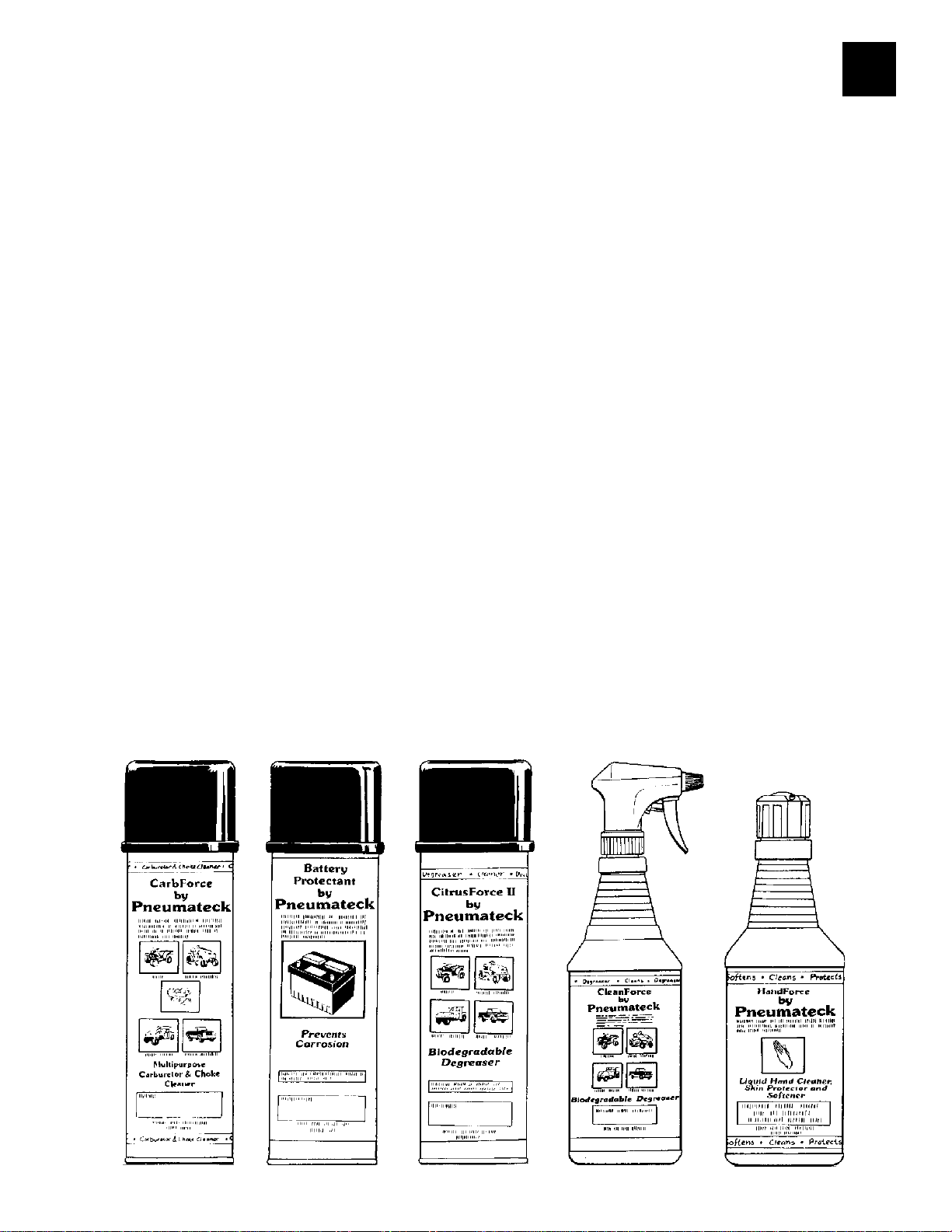
Cleaners and Lubricants
Sold in Case Lots Only
DIV. PLS PART # DESCRIPTION SIZE CASE SIZE
O92 192 81010C Multi-Purpose Cleaners & Degreaser 14oz can 12 cans
Biodegradable Citrus Force
O92 192 84010C Multi-Purpose Penetrant, Lubricant, Corrosion Preventive 15oz can 12 cans
& Moisture Displacer Fourway Force Case
O92 192 85010C Multi-Purpose White Lithium Grease Lithium Force 14oz can 12 cans
O92 192 87010C ‘Multi-Purpose Carburetor & Choke Cleaner Carb Force 15oz can 12 cans
O92 192 88010C ‘Multi-Purpose Battery Spray Protection Battery Protection 14oz can 12 cans
O92 192 89010C Contact Cleaners (Elec. Components) Refrigeration 14oz can 12 cans
O92 192 81410C Dry Teflon, Lubricant 10oz can 12 can
O92 192 82010C Multi-Purpose Cleaner and Degreaser Clean Force 32oz bottle12 bottles
O92 192 86010C Multi-Purpose Hand Cleaner and Skin Softener Hand Force 16oz bottle12 bottles
9
www.mymowerparts.com

For Husqvarna Parts Call 606-678-9623 or 606-561-4983
TECHNICAL TRAINING and SERVICE INFORMATION BOOKSTECHNICAL TRAINING and SERVICE INFORMATION BOOKS
TECHNICAL TRAINING and SERVICE INFORMATION BOOKS
1
Part NumberPart Number
Part Number
Part NumberPart Number
163578 Tractor & CRT Tiller Service Information Book
169291 1999 Craftsman & Wizzard Tractor, Mowers, Tiller Accessories
169418 1999 Craftsman & Wizard Tractor Wiring Schematics Book
168830 1999 Service Update Information Book
158222 1997 FHP Tractor Quick Reference Book
158223 1997 FHP Mowers / Tillers Quick Reference Book
158224 1997 FHP Tractor Wiring Schematics Book
168695 Deck Leveling Video
169287 Automatic Transmission/Drive System Video
139132 Electrical & Charging Systems Book
BLN-50432 HYDRO GEAR LT Hydro IHT Service & Repair Manual
BLN-50334 HYDRO GEAR GT Hydro 3010L Service & Repair Manual
99924-2041-01 KAWASAKI Engine Model FD590V 18HP Service Manual
TECHNICAL TRAINING and SERVICE INFORMATION BOOKSTECHNICAL TRAINING and SERVICE INFORMATION BOOKS
DescriptionDescription
Description
DescriptionDescription
from F.H.P. Source 917 order from D92/192
Book
Part NumberPart Number
Part Number
Part NumberPart Number
MS-8518 Troubleshooting Magnetron Ignition Systems (1985 Update)
MS-8798
MS-9152
MS-9557 Troubleshooting Carburetion Systems (1988 Update)
MS-9884
MS-2285 Carburetor Problem Solving Chart, page 10 (1991Update)
MS-2857 Troubleshooting Governor Systems (1993 Update)
MS-0279 Float Style Carburetor Leakage, page 27 (1994 Update)
MS-0575
MS-0981 Troubleshooting Carburetors (1996 Update)
MS-0709 OHV Gasket Chart
MS-0710 V-Twin OHV Gasket Chart
MS-2288 Alternator Chart
MS-3957 Air Filter Charts (2)
MS-3992 Handy Repair Check Chart
MS-5437 Single Cylinder L-Head Gasket Chart
MS-5441 Opposed Twin Gasket Chart
270962 Single Cylinder L-Head Engine MANUAL
271172 Opposed Twin Engine MANUAL
Part NumberPart Number
Part Number
Part NumberPart Number
692509 3 to 10 HP 4 Cycle "L" Head Engine MANUAL
691462A 8 to 18 HP Cast iron Engine MANUAL
691218 PEERLESS PowerTrain Components MANUAL
695244A 4 Cycle Overhead Valve Engines MANUAL
695907 Carburetor Troubleshooting Booklet
695590 4 Cycle Engine Failure Analysis Booklet
695933 Quick Reference Chart / Booklet
694862 Special Tools Booklet
DescriptionDescription
Description
DescriptionDescription
from BRIGGS & STRATTON Training & Ref. Mtl. (D92/192)
Quick Check, an Effective Troubleshooting Tool (1986 Update)
Systematically Troubleshooting Ignition, Carbureton and Compression
Troubleshooting Ignition, Starting, and Charging Systems (1991Update)
Troubleshooting - Ignition Tester, DC Shunt, Leakdown Tester (1995 Update)
DescriptionDescription
Description
DescriptionDescription
from TECUMSEH Source 143 Training & Ref. Mtl. order D92/192
Part NumberPart Number
Part Number
Part NumberPart Number
TP-2339 Command Single Cylinder CV11-CV16 Service Manual
TP-2450 Command Twin Cylinder CV18-CV25 Service Manual
TP-2289 Magnum Twin Cylinder MV18-MV20 Service Manual
TP-2131 Troubleshooting Flow Chart & Guidebook
ES-103 General Maintenance Video An Ounce of Prevention
ES-2007 Product Specifications; Sales Brochure on Models
TP-2372 Specifications & Tollerances Wallchart
ENS-967 Gaskets Wallchart
TP-2067 Air Cleaner Elements Wallchart
DescriptionDescription
Description
DescriptionDescription
from KOHLER Source 501 Training & Ref. Mti. order D92/192
10
www.mymowerparts.com

For Husqvarna Parts Call 606-678-9623 or 606-561-4983
Blade Bolt / Mandrel Nut
Blade Bolt to 30-35 Ft. Lbs.
Mandrel Nut to 55-65 Ft.
IMPORTANT BOLT TORQUES
TRACTORS:
Electric Clutch Bolt
Grade 5 Bolt
Torque to 50 Ft. Lbs.
Mechanical Clutch Bolt
Grade 5 Bolt
Torque to 35 Ft. Lbs.
1
Engine Mounting Bolts
Grade 5 Bolts
Torque to 35 Ft. Lbs.
STANDARD TORQUE VALUES
BOLTS, SCREWS, NUTS, AND FASTENERS
ASSEMBLED INTO CAST IRON OR STEEL.
11
www.mymowerparts.com

For Husqvarna Parts Call 606-678-9623 or 606-561-4983
1
TECUMSEH ENGINES OEM PLUG# GAP STD PLUG# OIL GRADE OIL CAPACITY
3HP thru 6.2HP, L Head
and HTL Rotary RJ19LM .030 PM4 30W 20.OZ
5HP thru 6.6HP Hi Torque
w/Extruded Carb. RJ19LM .030 PM4 30W 27.OZ
4HP, 5HP, OHV Rotary 6HP
OHV Slant Horizontal RN4C .030 NONE 30W 20.OZ
8HP, 10HP Vertical L Head RJ17LM .030 NONE 30W 32.OZ
12HP, 12.5HP Vertical
w/Stationary Cooling Air
Inlet Screen RL86C .030 NONE 30W 32.OZ
12HP, 12.5HP, 16.5HP OHV
Vertical w/Rotating Cooling
Air Inlet Screen NC4 .030 NONE 30W 32.OZ
BRIGGS AND STRATTON
3HP, 3.5HP, Classic 4HP, 5HP,
Quantum RJ19LM .030 PM4 30W 20.OZ
5HP Horizontal L Head RJ19LM .030 PM4 30W 20.OZ
8HP Horizontal L Head RJ19LM .030 PM4 30W 44.OZ
12HP, 12.5HP, 13HP Singles Cyl. RJ19LM .030 PM4 30W 48.OZ
15HP, 15.5HP OHV RC12YC .030 NONE 30W 48.OZ
14HP, 16HP, 18HP, 19HP,
Opposed Twins RJ19LM .030 PM4 30W 48.OZ
20HP Opposed Twin w/Filter RJ19LM .030 PM4 30W 56.OZ
13HP, 14HP, 15HP, 16HP, 17HP
Vanguard Single OHV + Intek/V RC12YC .030 NONE 30W 56.OZ
14HP, 16HP, 18HP, 20HP, 22HP
Vanguard Twin OHV+ Intek/V RC12YC .030 NONE 30W 56.OZ
KOHLER ENGINES
CV 12.5HP, 14HP, 14.5HP,
15HP, 15.5HP RC12YC .040 NONE 10W30 64.OZ
CV 20.5HP, 22HP
22.5HP, 25HP RC12YC .030 NONE 10W30 64.OZ
M18HP, 20HP, MV18HP,
18.5HP, 19HP, 20HP RV17YC .035 NONE 30W 56.OZ
HONDA ENGINE
5HP GXV140 NGK Brand NGKBPR5ES .030 NONE 30W 20.OZ
ONAN ENGINES
20HP RS14YC .025 NONE 30W 56.OZ
KAWASAKI
18HP NGK BPMRGA .025 CJ8 10W30 70.OZ
NOTE: Make sure the correct engine spark plug is used with (correct reach and heat range), as the use of a incorrect
spark plug will cause damage to the customer engine.
Tractor 1992 and newer with vented decks 3350 RPM + or - 50 RPM
Tractor 1991 and older with standard decks 3550 RPM + or - 50 RPM
Tractor low RPM single cylinder 1800 RPM
Tractor low RPM twin cylinder 1400 RPM
Rotary mower high RPM 3200 fast
Rotary mower low RPM 2600 slow
12
www.mymowerparts.com

For Husqvarna Parts Call 606-678-9623 or 606-561-4983
MAINTENANCE (M/A) CHECK
1
Tractor / Riding Mowers
• Tune engine, Check: rpm engine speed ,charging system , ignition, spark plug, throttle & choke
controls, clean engine cooling fins, replace air filter, change oil, oil filter, and fuel filter.
• Check & adjust tires for proper inflation.
• Lubricate moving parts, steering, linkage, and grease all fittings.
• Test overall operation of equipment and ensure that all safety features are operating properly.
• Check electrical system and clean battery terminals.
• Sharpen or replace cutting blades.
• Check blade mounting bolt Torque with Torque wrench ( 30 to 35 ft lbs).
• Check and adjust brakes & do brake test. See brake adjustment section for brake test.
• Compliance check operator present system and blade brake system, blades stop within 5 seconds
when disengaged.
• Check belts & pulleys.
• Adjust guage wheels, (off of ground).
• Check deck rake and level.
Tillers
• Remove fuel from tank & bowl.
• Tune engine , Check: rpm engine speed, Ignition, carburetor, clean or replace air filter and change
oil.
• Lubricate moving parts, pivot point and cable.
• Inspect, adjust or replace as needed all belts and chains as applicable.
• Test overall operation of equipment and ensure that all safety features are fully operational.
Snow Throwers
• Tune engine , Check: rpm engine speed , Ignition system, carburetor, battery, replace spark plug
and change oil winter weight only.
• Lubricate moving parts: pivot point, cables, auger shaft, grease zerk, and chains.
• Inspect, adjust or replace (as needed) all drive belts, belt guides.
• Check manual starter and electric starter if so equipped.
• Check and adjust disk drive assembly and auger cable.
• Check chute control rod and deflector.
• Test overall operation of the snow thrower.
• Check for proper operation of all safety features.
POKE HOLE IN TOP
OF FILTER HERE.
PREVENT OIL FROM SPILLING ALL OVER THE
WHEN CHANGING FILTER. POKING A HOLE
IN THE TOP OF THE FILTER WILL VENT SYSTEM
AND ALLOW OIL TO DRAIN OUT THROUGH
ENGINE SUMP.
13
www.mymowerparts.com
For Husqvarna Parts Call 606-678-9623 or 606-561-4983
1
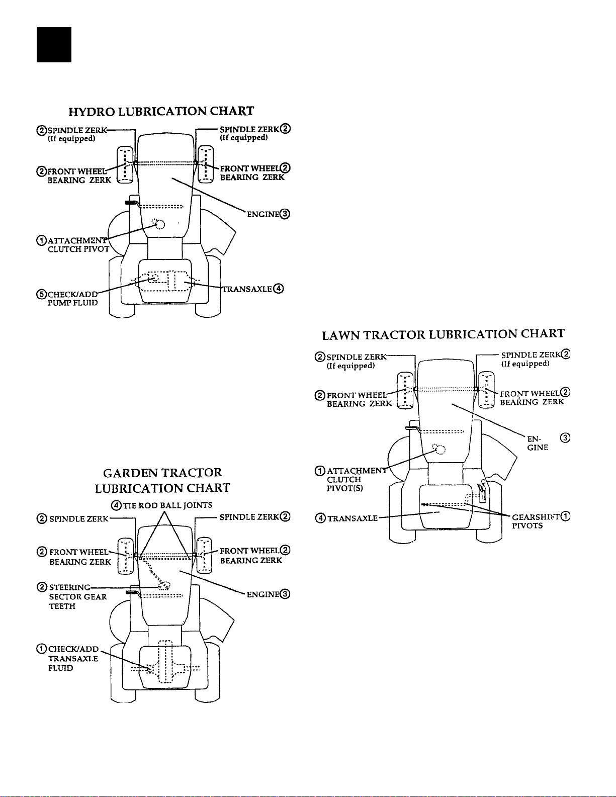
TRACTOR LUBRICATIONTRACTOR LUBRICATION
TRACTOR LUBRICATION
TRACTOR LUBRICATIONTRACTOR LUBRICATION
Important: do not oil or grease the pivot points which have special nylon bearings. Viscous
lubricants will attract dust and dirt that will shorten the life of the self-lubricating bearings. If you
feel they must be lubricated, use only a dry, powdered graphite type lubricant sparingly.
NOTE: HYDRO TRANSAXLE FLUID
Typically, a 20W-50 engine oil with an API
classification of SH/CD is recommended for
most normal operating conditions. In some
cases, such as northern climates where
temperatures commonly drop below 20°F it
may be necessary to perform seasonal oil and
filter changes to achieve the proper
performance levels expected from a hydrostatic
transmission. The recommended “winter” fluid
would then become a 10W-40 engine oil. An
alternative to seasonal fluid and filter changes
would be to use a synthetice engine oil such as
15W-50 Mobil 1. This choice offers not only
better cold weather performance, but also
improves high temperature protection over
both of the previously mentioned fluids. The
volume of fluid required to refill a transaxle is
approximately 2-1/2 quarts.
1. SAE 10W30 Motor Oil API-SG
2. General purpose grease
3. Refer to customer responsibilities "Engine"
section in owners manual.
4. Grease shell dorina type 0 20 oz.
5. SAE 20W50 Motor Oil API SG/CD
Lawn Tractor:
310-500, 310-650, 310-750 IHT Hydro
transmission holds approximately 80 oz.
20W50 motor oil.
Garden Tractor:
210-3010L GT Hydro transmission holds
approximately 60 oz. 20W50 motor oil or
10W40 or 15W50 Mobil 1 synthetic motor oil.
1. SAE 30 or 10W30 Motor oil API - SG
2. General purpose grease
3. Refer to customer responsibilities “Engine”
section in owner’s manual
4. Dana transaxle 16 oz. Shell dorina type 0
grease. Part number 120416X
1. SAE 30 Motor Oil API-SF/SG holds 128 oz.
2. General purpose grease.
3. Refer to customer responsibilities "Engine"
section.
4. Spray silicone lubricant (move boots to
lubricate)
www.mymowerparts.com
Peerless transaxle: 30 oz. Bentonite grease.
NOTE:NOTE:
NOTE: on transaxle with grease, only change or
NOTE:NOTE:
add grease when making repairs to the inside of
transaxle.
IMPORTANT:IMPORTANT:
IMPORTANT: do not oil or grease the Pivot
IMPORTANT:IMPORTANT:
points which have special nylon bearings.
Viscous lubricants will attract dust and dirt that
will shorten the life of the self-lubricating
bearings. If you feel they must be lubricated
use only a dry, powdered graphite type
lubricant sparingly.
14

For Husqvarna Parts Call 606-678-9623 or 606-561-4983
SERVICE ORDER DOCUMENTATION
1
It’s important to always document the reason for failure on the service order. On an in-warranty
product, do not close the service orders as in-warranty, if the failure is due to customer abuse, neglect
or even accident. Verify and document as much information as possible about a service call on the
service order. Especially when a major component has been replaced, here are a few examples of
acceptable and not acceptable service orders.
1 - NOT ACCEPTABLE
A. Service Requested: Won’t Run
B. Tech Comments: Replaced Engine
2 - ACCEPTABLE
A. Service Requested: Won’t Run
B. Tech Comments: Found black, dirty oil in pump, connecting rod broken.
Customer abuse, changed engine, tested for safety compliance and charged customer.
C. Call closed as collect
3 - ACCEPTABLE
A. Service Requested: Won’t Run
B. Tech Comments: Found engine locked. Oil normal, no external causes found.
Internal component failed. Replaced engine and tested.
C. Call closed as in-warranty
Note: The cost of an engine replacement must be supported by what you have determined caused the
failure.
Engine Replacement
Other than catastrophic internal engine failures, ordering a replacement engine is not
always the solution. Many perfectly good engines have been received and inspected
at the Dallas Rebuilding facility. Before replacing an engine check the following items
first:
Complaint:
Noisy
• Disconnect belt(s), run engine with no load.
• If an engine is noisy, determine where noise is coming from. If engine runs normally but has a knock,
pull head(s) and check for carbon buildup.
High Oil Consumption
• Is it leaking or burning oil?
• Check integrity of all seals and gaskets (as described in the Troubleshooting section of this manual).
• Ensure breather is operating properly.
• Check condition of spark plug. An oil-fouled plug will indicate engine is burning oil.
• Check oil type, quality and quantity.
• Does the engine smoke? If so, is the smoke black, white or blue?
Won't Run / Locked Up
• Disconnect belt(s), run engine with no load.
• Check external causes.
• Check starter drive to ensure it is not jammed in the flywheel.
15
www.mymowerparts.com
For Husqvarna Parts Call 606-678-9623 or 606-561-4983
2
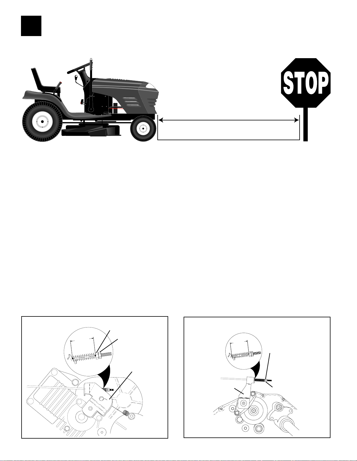
BRAKE ADJUSTMENTS
6 FEET
BRAKE TEST
A brake test should be performed whenever Service work is performed on a tractor. Tractor traveling at high speed in highest
gear must stop within 6 feet when the brakes are applied. If tractor requires more than 6 feet to stop, a brake adjustment
should be made before returning tractor to the customer.
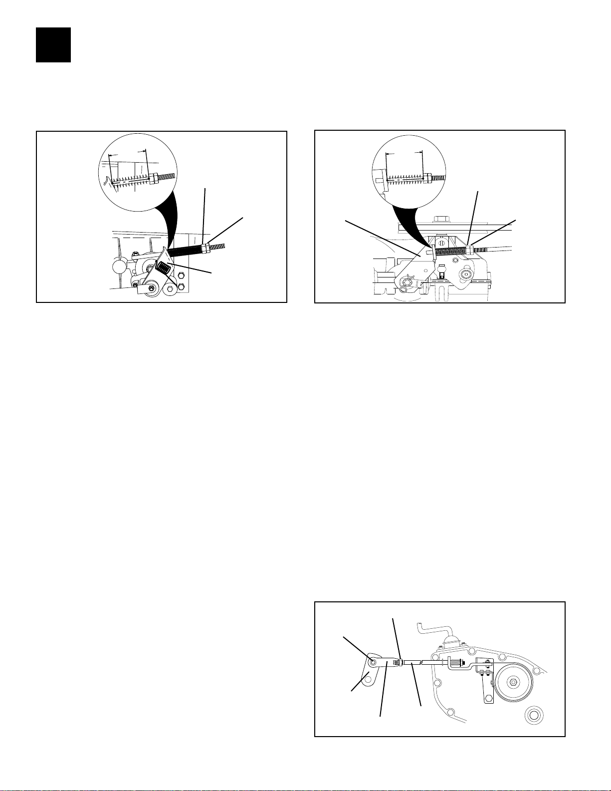
TO ADJUST BRAKE
Your tractor is equipped with an adjustable brake system which is mounted on the side of the transaxle.
• Depress clutch/brake pedal and engage parking brake.
• Measure distance between brake operating arm and nut “A” on brake rod.
• If distance is other than dimension shown for your type tractor, loosen jam nut and turn nut “A”
until correct distance is reached. Retighten jam nut against nut “A”.
VGT HYDRO TRANSAXLE AYP DISC BRAKE TRANSAXLE
WITH PARKING BRAKE “ENGAGED”
NUT
“A”
1-1/2"
JAM
NUT
OPERATING
ARM
WITH PARKING BRAKE “ENGAGED”
1-3/4"
NUT
“A”
OPERATING
ARM
16
www.mymowerparts.com
JAM NUT
For Husqvarna Parts Call 606-678-9623 or 606-561-4983
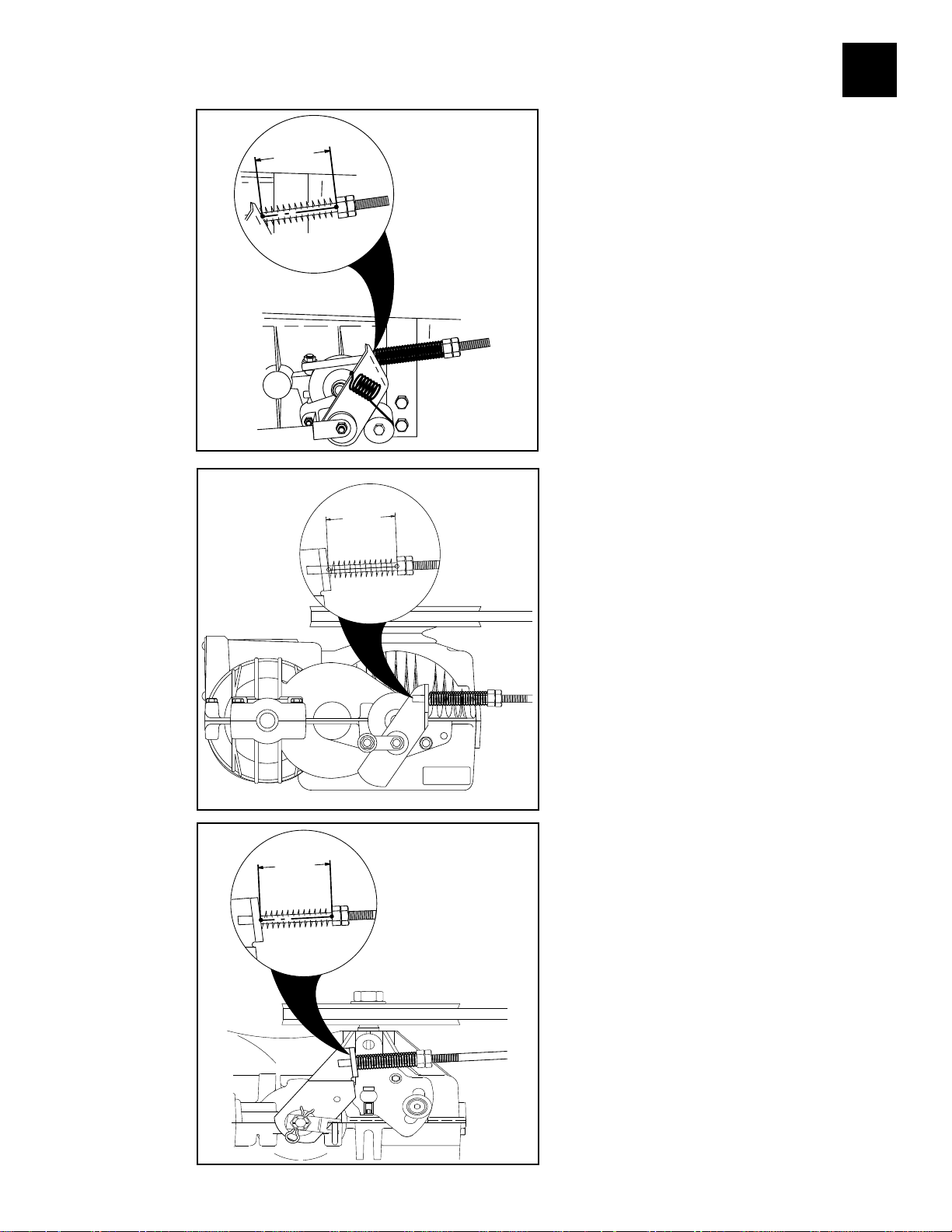
LAWN RIDER
1-1/2"
Brake adjustments
2
1-1/2"
PEERLESS HYDRO
Brake adjustments
1-1/2"
HYDRO GEAR 3000
Brake adjustments
17
www.mymowerparts.com
For Husqvarna Parts Call 606-678-9623 or 606-561-4983
2
BRAKE ADJUSTMENT
STEP-THRU LT/YT GEAR DRIVE
TRANSAXLES PEERLESS + DANA
SHOWN WITH
1-1/2"
PARKING BRAKE
"ENGAGED"
NUT "A"
JAM NUT
OPERATING
ARM
STEP-THRU LT/YT HYDROGEAR
0500/0650
SHOWN WITH
1-9/16"
OPERATING
ARM
PARKING BRAKE
"ENGAGED"
NUT "A"
JAM NUT
GT BRAKE BAUD BRAKE ADJUSTMENT
IMPORTANT: DO NOT OVER TIGHTEN BRAKE. WHEN DEPRESSING CLUTCH BRAKE PEDAL, THE MOTION DRIVE
BELT MUST STOP MOVING (DECLUTCH FROM ENGINE PULLEY) BEFORE BRAKE ENGAGES. IMPROPER
ADJUSTMENT WILL CAUSE HARD SHIFTING AND EXCESSIVE WEAR TO BRAKE LINING.
• Park and turn off the tractor on a level surface.
Place gear shift lever in neutral (N) position.
Disengage parking brake and be sure tractor
does not roll in either direction.
• Lower mower deck (if installed on tractor).
• Snap out access hole cover on left side of tractor
above footrest.
• Loosen jam nut at clevis which will allow brake
rod to be rotated.
• With pliers, from underside of frame, unscrew
brake rod from clevis four (4) to six (6) full turns.
• Start tractor with gear shift lever in neutral (N)
position.
• Slowly depress clutch/brake pedal to the point
where the motion drive belt stops moving. Hold
clutch/brake pedal in this position and engage
parking brake. If belt begins to move after engaging parking brake, reset parking brake by
depressing clutch/brake pedal slightly to next
notch on parking brake.
• Stop engine. Screw brake rod back into clevis
until clevis pin is against rear edge of slot in
brake arm. Do not over tighten (see “IMPORTANT” above).
• Tighten jam nut against clevis.
• Replace access hole cover.
• Road test tractor for proper stopping distance
and declutching as stated above. Readjust if
necessary. If proper adjustment cannot be
attained, replace brake band.
GT BAND BRAKE TRANSAXLE
JAM NUT
CLEVIS
PIN
BRAKE
ARM
CLEVIS
BRAKE
ROD
18
www.mymowerparts.com

For Husqvarna Parts Call 606-678-9623 or 606-561-4983
TRANSAXLES
3
WHAT YOU SHOULD CHECK BEFORE YOU REPLACE THE TRANSAXLE
Symptom: Hard Shifting / Transaxle locked up.
Eliminate all customer issues: Make sure customer is not shifting on the go or is trying to shift on
a hill. Shifting on the go will damage transaxle, shifting on a hill is incorrect due to the gear load.
Jerking is caused by clutch misuse. Do not replace transaxle, instruct customer how to use clutch.
Surging happens when a tractor goes down hill and momentarily picks up speed (this is normal).
Remember you cannot fix something on a transaxle that is normal (not broken).
1. Place tractor on level ground.
2. Remove drive belt from transaxle input pulley.
3. If transaxle shifts OK. Tractor has a belt guide out of adjustment or belt guide is missing.
4. Verify that both square axle keys are installed in each wheel hub.
5. Verify shift lever linkage is secure (all fasteners are tight).
6. Check brakes/clutch dwell setting for proper adjustment (verify brake return spring is installed).
7. If transaxle is still locked up you have a internal problem in the transaxle, repair or replace.
8. Note: 30% of all transaxles returned to the rebuild center have nothing wrong with them.
Set Parking Brake: Check the brake clearance it should be. 019"/.024" between the brake disc and
the outside friction puck while the brake lever contacts the brake jaw.
Compliance brake test: tractor on level ground at full speed in highest gear must stop within six (6)
feet or less. If unit fails, follow brake adjustment procedures on page 16, 17 and 18 of this manual.
BRAKE DISC
OUTSIDE FRICTION PACK
.019 BRAKE PUCK CLEARANCE
.024 WITH LEVER CONTACTING
BRAKE JAW BOSS
19
www.mymowerparts.com

For Husqvarna Parts Call 606-678-9623 or 606-561-4983
3
Oil and filter change should occur approximately every 200 hours of operation or when oil condition results in loss of power. More frequent oil and filter changes are recommended if operation
conditions are severe or adverse, such as pulling a plow or a tiller for an extended period, or
operating in very dusty conditions.
• Run tractor to heat up oil (Warm oil will drain more freely).
• Be sure tractor is on level surface and catch oil in a suitable container.
Lift tractor off the ground with lift at the drawbar of the tractor or block up tractor so the left rear
wheel is just off the ground and remove left rear tire (Be sure to keep tractor as level as possible).
(#1) Remove oil filter.
(#2) Remove hose from end of swivel fitting at oil drain location.
(#3) After oil has drained completely, replace hose end to swivel fitting and tighten securely
(#4) Put a small amount of oil on the filter rubber seal before installing. Install the new filter and
tighten 3/4 of one turn after the filter seal touches the filter mounting base, to prevent an air leak.
Order the proper replacement filter from AYP.
(#5) Remove oil level port plug.
(#6) Remove vent cap from end of oil fill tube and refill transaxle with about 45 ounces of 15w50
Synthetic Mobil one engine oil . Fill oil through the oil fill breather vent hose until just before the oil
starts to come out of the oil level port hole. Pour slowly do not overfill, let excess oil drain out of
oil level port hole.. Note the system holds 60 ounce of oil but you will only get out about 75%
during a oil change. About 25% of the oil will remain in the pump for a prime to restart the system
after the oil change.
(#7) Replace oil level plug and purge transaxle as follows:
• Engage parking brake and place freewheel control in “freewheel” position.
• Sit in seat, start engine and move throttle control to “slow” position.
• Put motion control lever in neutral (N) and slowly disengage clutch/brake pedal.
• Move motion control lever to full forward position and hold for five (5) seconds.
(#8) After purging the system of air andonce tractor has been running for one minute, the oil level
should be rechecked. Remove oil drain port hole plug and add 2 to 4 ounces or more oil if needed.
Reinstall oil drain port hole plug and the vent cap to oil fill tube. Refer to step#6.
HYDRO TRANSAXLES - GT OIL/FILTER CHANGE
Move lever to full reverse position and hold for five (5) seconds.
Repeat this procedure three (3) times.
OIL LEVEL
LEFT SIDE VIEW RIGHT SIDE VIEW
PARKING BRAKE ARM
BREATHER
VENT / OIL FILL
TUBE
FREEWHEEL CONTROL
OIL DRAIN SWIVEL PLUG
20
(BYPASS VALVE)
www.mymowerparts.com
OIL FILTER
For Husqvarna Parts Call 606-678-9623 or 606-561-4983
HYDRO TRANSAXLES - GT TROUBLESHOOTING
3
Symptom: Hydro Garden Tractor Won’t Drive.
Trouble shooting Cold starting for hydro (below 40 degrees F) after starting engine and before
driving , let the transmission warm up for (1) minute by placing the motion control lever in neutral
(N) position and releasing clutch/brake pedal.
1. Follow purge procedures described in step #7 on page 20 of this manual.
2. Place free wheel control in the drive position.
3. Check for proper installation and function of motion drive belt.
4. Verify that the axle engagement key is in place in both rear wheel hubs..
5. Verify motion control linkage is secure (all fastener are tight).
6. Verify proper oil level in transmission, remove oil level port plug and check oil level. Oil should
be at the bottom of the plug hole, but not running out.
7. Verify parking brake arm releases..
8. Test for system leaks ( fitting, hoses, seals, ect ) see test procedures.
PARKING BRAKE
The brake was factory set for specific running
clearance between the disc and pucks of 0.020".
Place a feeler gage between the disc and one puck,
if the clearance is not set properly remove the
cotter pin retaining the castle nut and set the correct clearance by adjusting the castle nut accordingly. Reinstall the cotter pin. Compliance brake
test: Check Brakes operation, tractor at full speed
in high gear must stop within six (6) feet or less
on level ground.
Test Procedure for System Leaks:
1. Remove vent from breather hose ( located at
the rear tractor on top of the hydro
transaxle).
2. Apply (5) to a maximum of (10) psi air pressure
to the hose.
3. If a leak is present, a puddle of oil should begin
to form under the transmission in less then (2)
minutes. Determine the origin of the leak.
4. If no leaks are found, change filter and oil.
5. If leak is found repair or replace defective
components.
6. Check level and top off with recommended oil.
7. Follow purge procedures as described in step #7
on previous page of this manual.
8. If tractor functions properly, check oil level and
top off with recommended oil if needed.
9. If tractor still won’t drive replace hydro/pump
(or) defective component) and follow
recommended start up purge procedures.
INSERT 0.020"
FEELER GAUGE
HERE
LEFT SIDE VIEW
PARKING BRAKE ARM
RIGHT SIDE VIEW
APPLY 5 TO 10 P.S.I. OF AIR
TO THE BREATHER HOSE
CHECK
FOR OIL
LEAKS IN
THESE
AREAS
(FITTINGS)
21
www.mymowerparts.com
For Husqvarna Parts Call 606-678-9623 or 606-561-4983
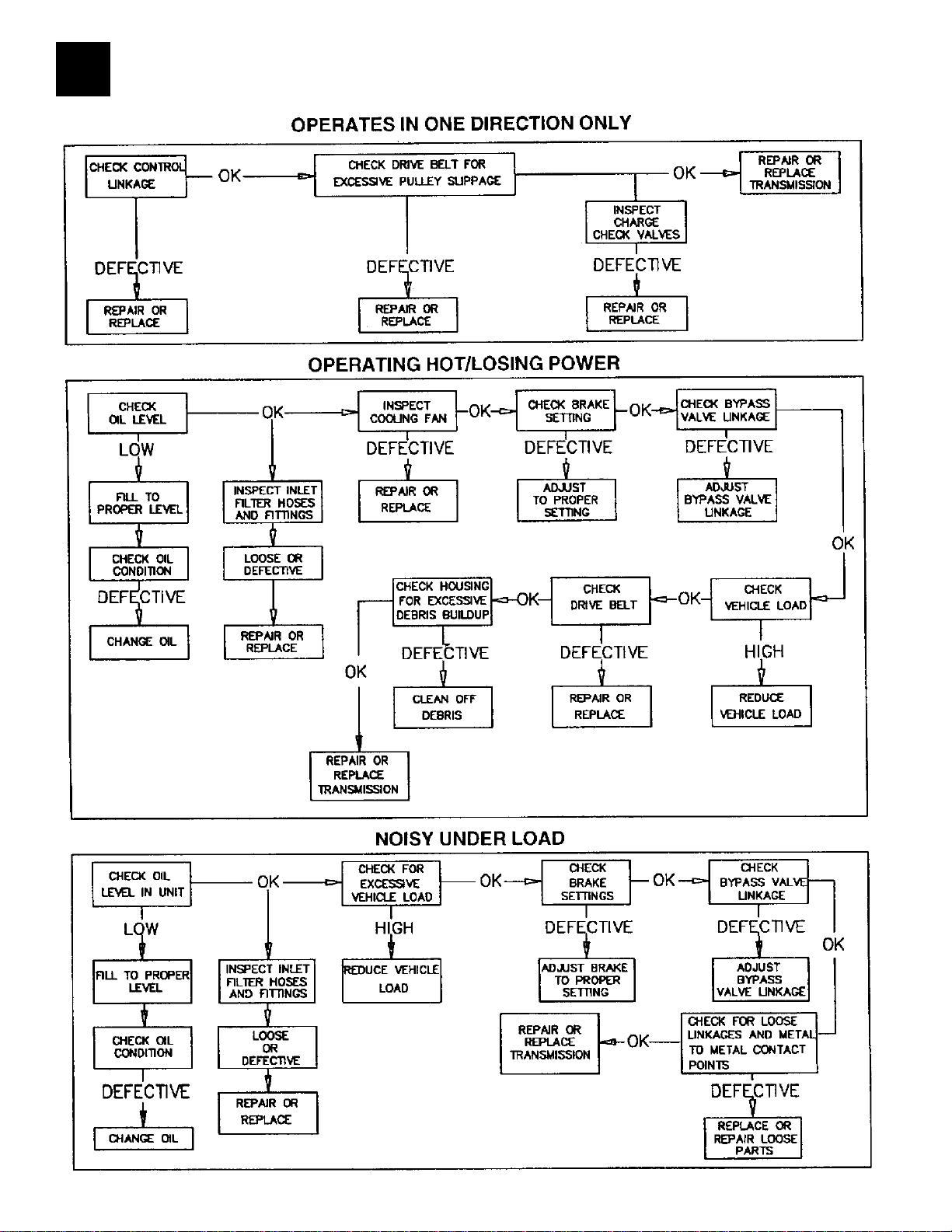
3
TROUBLESHOOTING CHART
GARDEN TRACTOR WITH HYDRO GEAR TRANSAXLE
22
www.mymowerparts.com

For Husqvarna Parts Call 606-678-9623 or 606-561-4983
HYDRO TRANSAXLES - LT REPLACEMENT
3
WHAT YOU SHOULD CHECK BEFORE YOU REPLACE THE TRANSAXLE
Symptom: Tractor has loss of drive. No forward / reverse motion.
1. Check to see that the freeweel control is “DISENGAGED” position.
2. Make sure the motion drive belt is not worn , damaged or broken.
3. Vehicle should be on level ground before performing adjustments.
4. Verify that square axle key are installed in each wheel hub.
5. Was air trapped in hydro transaxle during shipment? (PURGE TRANSAXLE.)
6. Adjust the neutral position. Make sure shift lever linkage is tight.
7. Does hydro transaxle have enough oil ? Check oil level and add if needed..
8. Check the parking brake setting.
Set Parking Brake :
1. Adjust the nut onto brake bolt until tight or until the brake arm will not move.
CAUTION! do not over tighten the nut or damage may occur to the brake assembly.
2. Back nut off 2/3 turn (4 to 5 flats); place a 0.030" feeler gauge between the two outer discs to set
air gap.
3. Reinstall the cotter pin or second new nylon insert locking nut to lock the brake setting.
Bolt without hole requires use of Spring and 2 Locknuts Bolt with hole requires the use of Spring and Cotter Pin
Place 0.030"
Feeler Gauge here
Back off nut 4 to 5 flats
(2/3 of one turn = 0.030")
23
www.mymowerparts.com
For Husqvarna Parts Call 606-678-9623 or 606-561-4983
3
HYDRO TRANSAXLES - TROUBLESHOOTING
SYMPTOM: TRANSAXLE NOISY
Note: The average Hydro-transaxle has a different sound level.
1. Check oil level as previously described, using a ruler for LT tractor and oil level port for GT.
2. Check cooling fan ( if applicable) for obstruction and/or broken fins, if fan blade is broken, re-
place, to keep the transaxle running at optimum performance keep the area clean. It’s recommended to use air to clean off debris. Although, using a garden hose (low pressure) with water is
acceptable as long as the transaxle is completely cooled down, for example clean with water before
the customer cuts the grass or after, as long as the tractor has sufficient time to cool down.
3. Check brake setting to ensure that it has the proper clearance and that the puck is not giving
resistance during freewheel. To check brake clearance; place a feeler gauge between the two outer
discs, if the clearance is out of range (.020"-.040" for LT tractor and .020"-.025" for GT tractors),
adjust the break retainer as needed to bring clearance into this range.
4. Check bypass valve linkage to insure that the bypass valve is fully opening and closing when the
actuator is activated.
5. Verify axle key is in place and in one piece.
HYDRO TRANSAXLES - LT TROUBLESHOOTING
SYMPTOM: ENGINE RUNS, TRACTOR WON’T DRIVE
1. Check bypass actuator to insure that it is in the “Drive” position.
2. Check belt integrity and that there is not excessive slippage on the input pulley. If the belt is
worn, dry rotten, broken, etc., replace and adjust.
3. Check oil level, the 310-0500 and 310-0750 holds approximately 80 ounces of 20W50 SG/CD
grade oil (or in cold weather 15W50 Mobil One synthetic oil is recommended) To check oil level:
remove vent hose and fitting. Put tape measure inside vent hole and measure oil level
On model 310-0500: the oil should be between 1.25" and 2.00" from top of housing.
On model 310-0650/0750: the oil should be between 1.00" and 1.75" from top of housing.
To add oil, remove vent hose and fitting. Add
oil until proper oil level for either type transaxle
is reached. Note: If oil level is found low, find
the cause of the problem, check the input seals,
bypass seals, and axle key. If needed, perform
the pressure test to find the leak.
4. If tractor still does not move, check shift
linkage to be sure the shift lever is fully actuated.
5. Check brake and verify that the brake is
adjusted properly and the tractor freewheels
when the transaxle is in the transport position.
TO ADD OIL: Remove breather hose and
fitting. Add oil until proper oil level for
transaxle type is reached.
BREATHER
HOSE
MEASURE
OIL LEVEL /
ADD OIL
HERE
RULER OR
TAPE MEASURE
24
www.mymowerparts.com
For Husqvarna Parts Call 606-678-9623 or 606-561-4983
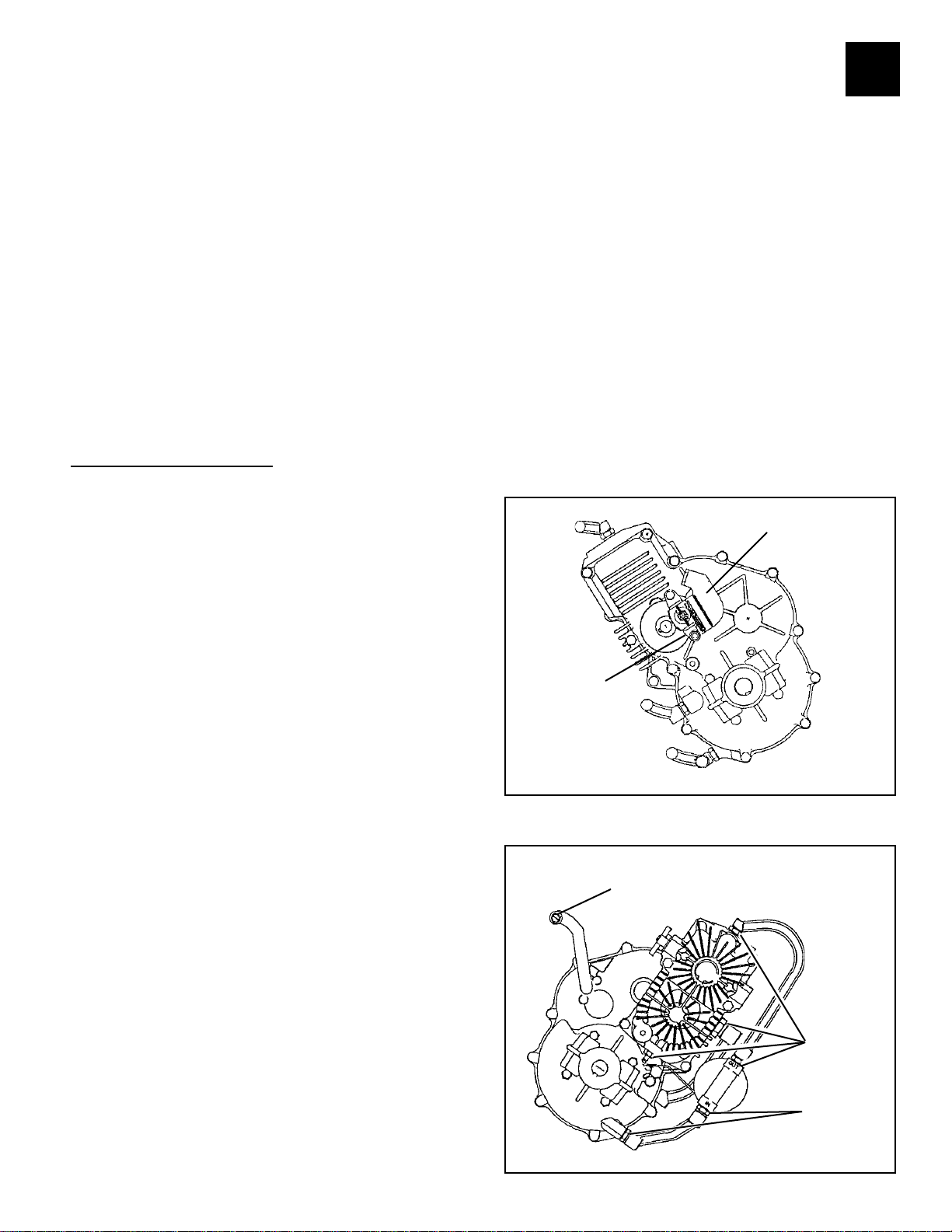
HOW TO ADJUST MOTION CONTROL LEVER ON VST PEERLESS HYDRO
The motion control lever has been preset at the factory and adjustment should
not be necessary.
If for any reason the motion control lever will not hold its position while at a
selected speed, it may be adjusted as follows:
• Park tractor on a level surface. Stop tractor by turning key to "OFF" `
position and engage parking brake.
NOTE: Transmission should not be warm when making this adjustment.
Allow transmission to cool to airtemperature before making this adjustment.
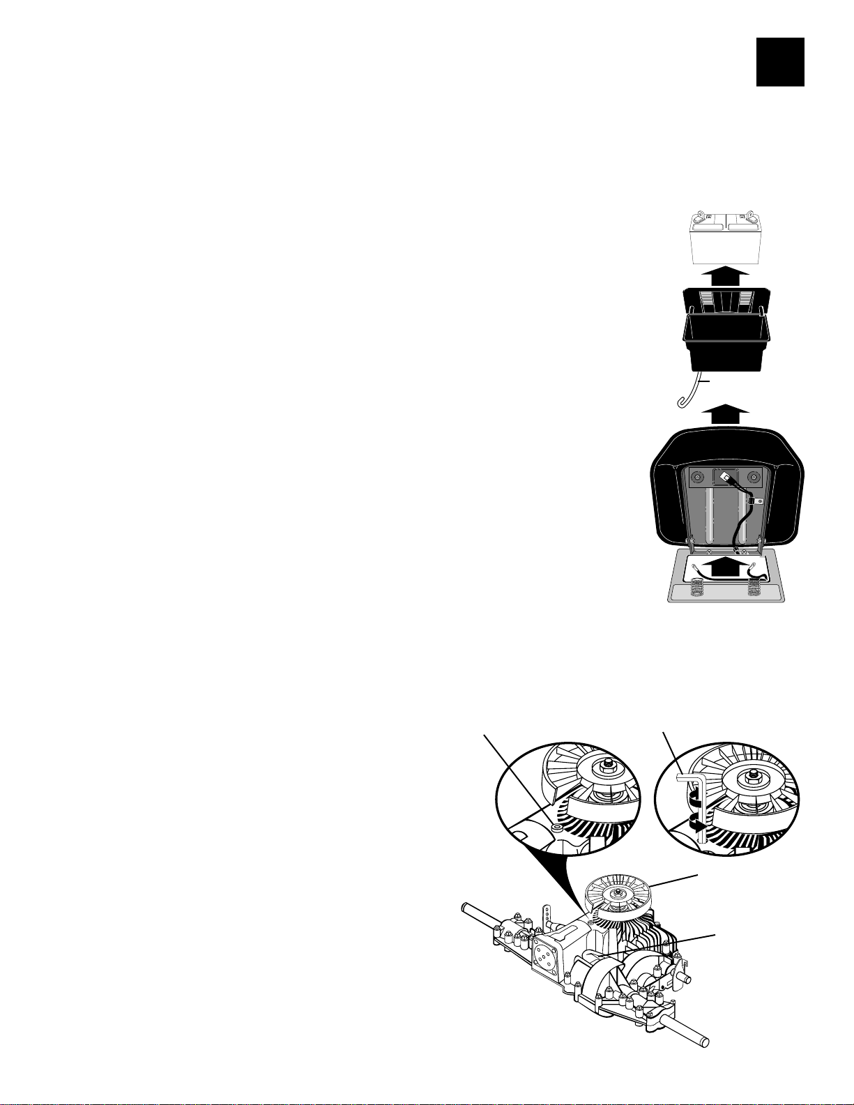
To access the transmission adjustment, it will be necessary to remove the
battery and the battery box from tractor.
• Raise seat and open battery box door. Disconnect BLACK battery cable
first, then the RED cable.
• Remove battery and battery box from tractoras shown.
NOTE: When reinstalling battery box, ensure that battery acid drain tube is
routed toward the rear and is clear of the cooling fan.
• Locate the access plug underthe cooling fan. This plug and surrounding
area must be cleaned to prevent contamination of internal parts during
this procedure. Before removing the plug, pack a cloth in the housing
pocket to absorb excess oil.
• Using needle nose pliers, remove the access plug described above.
When the plug is removed, a small quantity of oii will flow out of the
transmission. This is normal and will not effect-transmission function.
• Insert a #30 torx or 5/32 alien wrench into the access hole and locate the
adjustment screw. Adjust the screw clockwise 1/4 turn at a time to
increase motion control effort. An effort of 15-18 Ibs. at the motion
control lever knob is nommal.
NOTE: If for any reason the effort to move the motion control lever becomes
too excessive, reverse the above procedure by turning the adjustment screw
counterclockwise 1/4 turn.
• Clean the access plug and insert it into position using the torx or alien
wrench.
• Clean spilled oil from transmission and
reinstall battery box and battery
into tractor. When connecting battery be
sure to connect the RED bat
tery cable first. Road test tractor after
adjustment and repeat procedure
if necessary.
ACCESS PLUG
WRENCH
BATTERY ACID
DRAIN TUBE
3
25
www.mymowerparts.com
COOLING FAN
HOUSING
POCKET

For Husqvarna Parts Call 606-678-9623 or 606-561-4983
3
SECTION 11. VST TROUBLESHOOTING
The information on the following pages has been provided to help understand the internal operation of the VST. Do not use this information to attempt any internal repairs. Tecumseh's current
policy on hydrostatic transaxles that have internal failures is to replace the complete unit. This has
not changed. However, Tecumseh would like to provide a failure checklist to assist in making an
accurate evaluation of the complete tractor to eliminate any unnecessary replacements. Here is a list
of items to check and corrective actions to take.
To properly test the unit for power loss.
1. Allow the unit to cool before trying the following steps.
2. Put the shift lever in a position that is 1/2 of the travel distance from neutral to forward.
3. Place the tractor on a 17 degree grade.
4. Drive the tractor up the grade (without the mower deck engaged). The loss of power
experienced should be approximately 20%. This is considered normal. If the loss of power is
approximately 50%, this would be considered excessive.
5. Bring the unit to neutral, shift into forward and note the response. Care should be taken to
move the lever slowly to avoid an abrupt wheel lift.
To detemmine if the problem is with the hydro unit, all external problem possibilities must be
eliminated. Here are some potential problem areas.
1. Overheating: Heat can cause a breakdown in the viscosity of the oil which reduces the
pressure used to move the motor. Remove any grass, debris, or dirt buildup on the transaxle
cover and / or between the cooling fins and fan. Buildup of material will reduce the cooling
efficiency.
2. Belt slippage: A belt that is worn, stretched, or the wrong belt (too large or wide) can cause
belt slippage. This condition may have the same loss of power symptom as overheating.
Typically, the unit which has a slipping belt will exhibit a pulsatina type motion of the
mower. This can be verified visually by watching the beTt and pulley relationship. It the
belt is slipping, the belt will chatter or jump on the pulley. If the belt is good, a smooth
rotation will be seen. Replace the belt and inspect the pulley for damage.
26
www.mymowerparts.com
For Husqvarna Parts Call 606-678-9623 or 606-561-4983
3
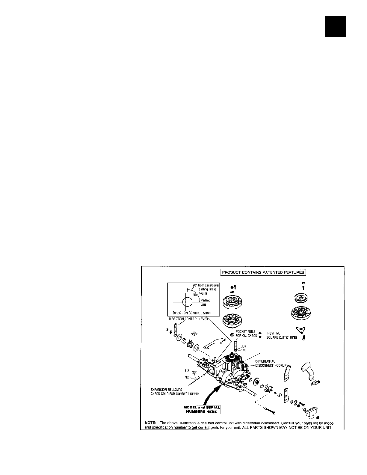
3. Leakage: The VST and 1800 Series have two oil reservoirs which can be checked for diagnostic
purposes. The first is the pump and motor expansion bellows, With a small diameter blunt or round
nose probe, check the bellows depth through the center vent hole. Proper depth from the edge of
that hole is 3-1/4 - 3-1/2 inches (8.25 - 8.9 cm).
The second chamber is for the output gears including the differential. FIRST make sure the tractor is
level, then remove the drain/fill plug. NOTE: Some units that do not have differential disconnect
will have two plugs. We recommend using only the primary plug. With a small pocket rule insert
until you touch bottom of case. You can then remove it and check for 1/4 - 3/8 inches (6.5 - 9.5 mm)
contact. This is full at its 8 oz. capacity of SAE EP 80W90 oil.
4. Low ground speed: If the linkage is not synchronized to absolute neutral, or the shift lever is not
properly fastened to the tapered control shaft, full forward travel may not be achieved. This may
cause a false reading and be misdiagnosed as a low power condition. This also could be caused by
the brake not releasing.
To detemmine absolute neutral, the hole in the tapered control shaft must face straight up and
down, at this point make sure the OEM linkage is in neutral. To properly fasten the control lever to
the shaft, torque the nut to 25-35 ft. Ibs. (34 - 48.3 NM) of torque with the shaft and the lever in
neutral.
When attaching the shifter arm to the shaft you must prevent any rotation during torquing. This
can be done by placing a long 5/16 bolt in the hole as shown in Illustration. Hold the bolt until the
tapers are locked and the nut torque is correct.
To make sure that the brake is not binding, drive the unit up a slight grade. Position the speed
control lever into neutral. The unit should coast backwards. If the unit does not coast back slowly,
the brake is not released from the brake disk. Adjust the brake linkage to release the brake completely when the foot pedal is released.
5. Hard to shift: Typically hard
to shift symptoms are not caused
by the hydrostatic unit. The shift
arm should move with relative
ease. Approximately 40-50 inch Ibs.
(4.48 - 5.6 NM) at the transaxle for
foot pedal units or 150-200 inch Ibs.
(16.8 - 22.4 NM) for hand operated
units. This varies depending on the
type of linkage. Binding may occur
in the linkage connections due to
rust or moisture. Lubricating these
connections and checking for bent
or damaged parts should resolve
hard shifting.
27
www.mymowerparts.com
For Husqvarna Parts Call 606-678-9623 or 606-561-4983
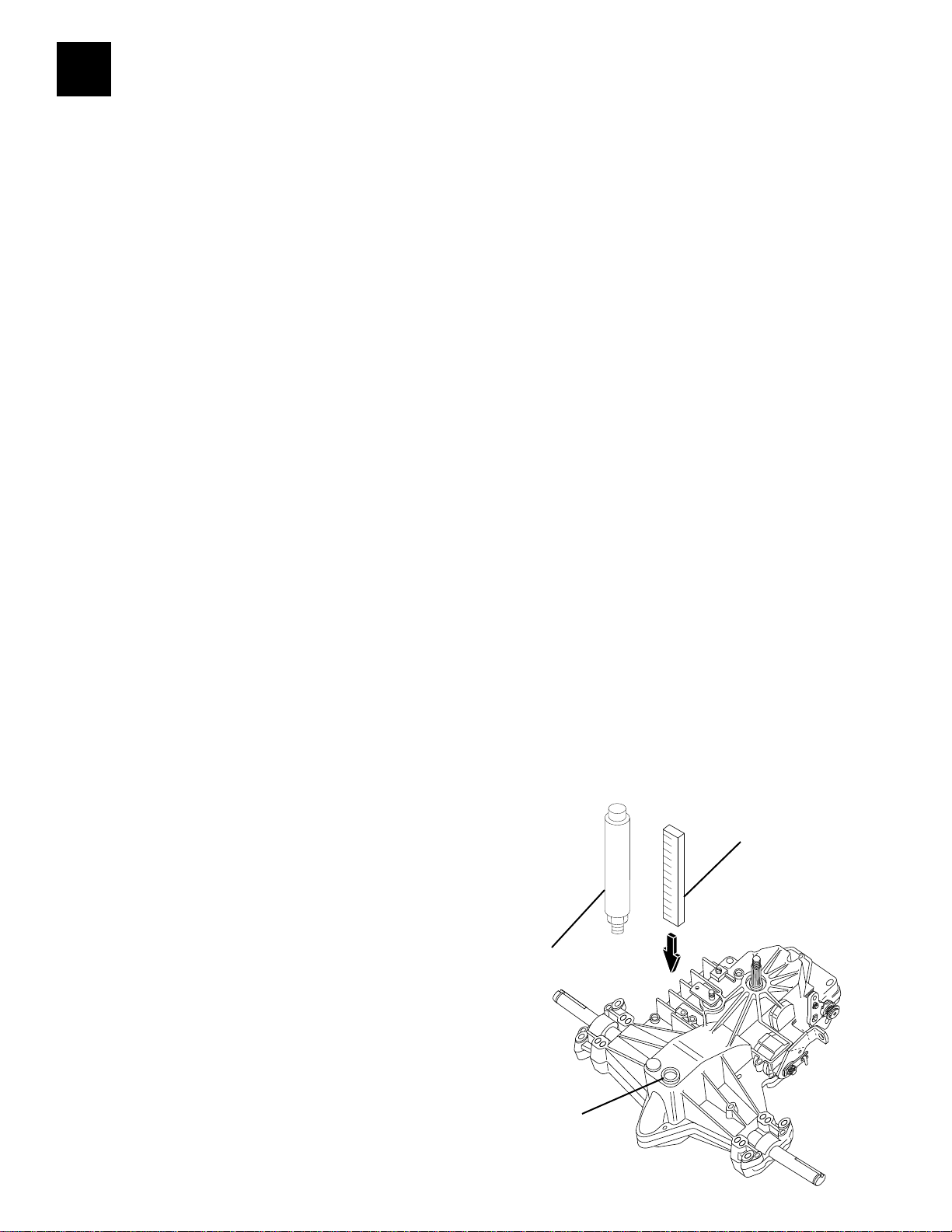
3
To install the friction pack kit first take these precautions. 1 ) Park the mower on a level surface. 2)
Make sure the parking brake has been set.
Raise the rear of the mower off of the ground and rest it on a stable support. Block the front wheels
to prevent the mower from rolling off the support. Remove the left rear wheel (in the operators
position) to expose the shifting linkage. Disconnect the turnbuckle shifting linkage at the pivot
point of the control arm and turn the control arm counter clockwise until it stops. To help accomplish this it may be necessary to place a 5/16 pin punch in the hole in the shifter shaft just behind
the control arm. Putting the punch in from the bottom side will provide increased leverage.
To mount the kit on the transaxle, angle the bracket so that it will clear the opening in the bracket
for the nut on the shifter shaft. Align the two bracket mounting holes up with the axle housing thru
holes. Fasten the bracket to the housing securing it with the two (2) 3/8" diameter self threading
bolts included in your kit.
FRICTION PACK KIT INSTALLATION 71/143 799026
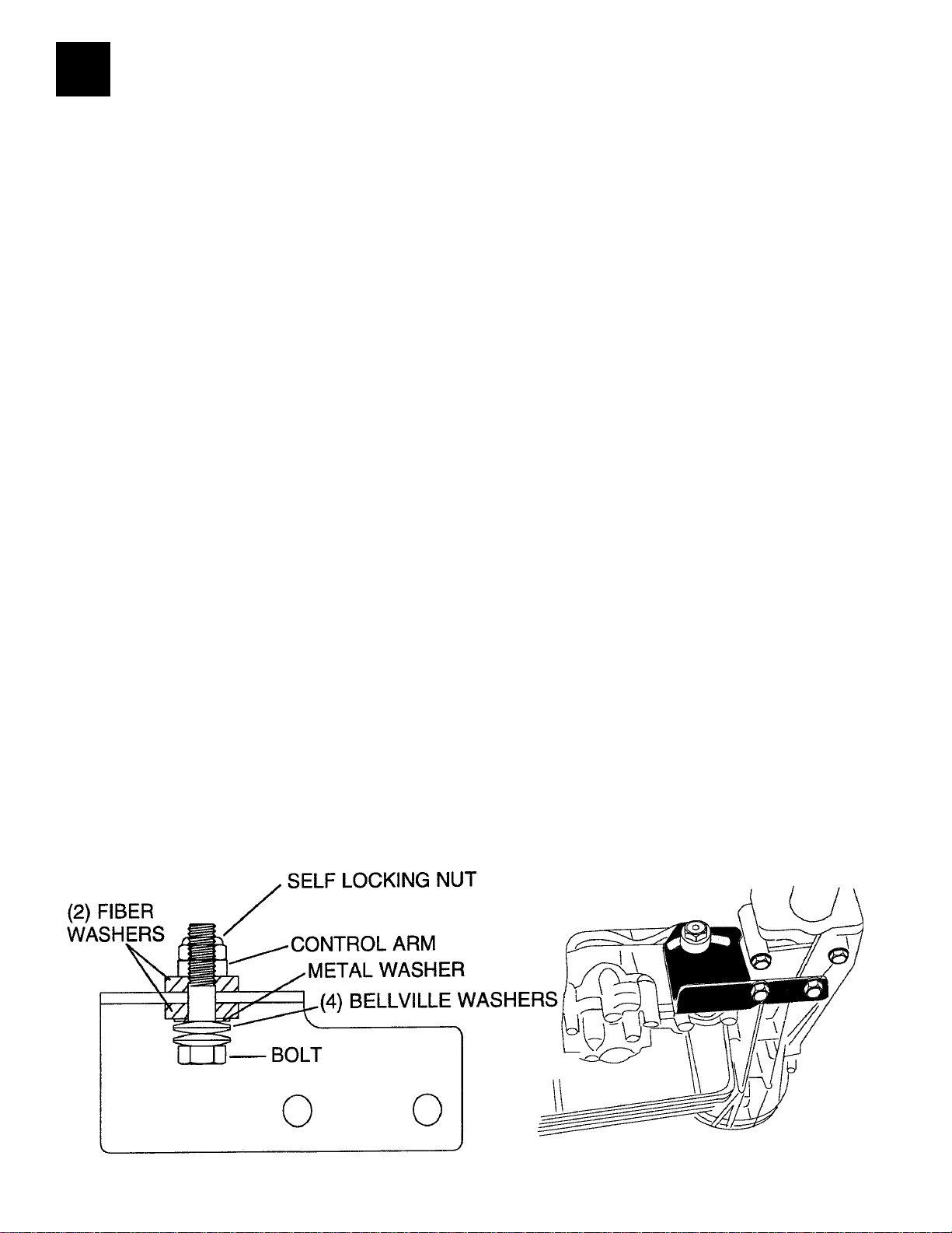
Place the four (4) belleville washers on the remaining bolt so that the cupped sides face each other,
followed by a metal washer and a fiber washer. Place this assembly through the arced slot in the
bracket and the second fiber washer and the control arm securing the entire assembly with the
compression nut. Return the control arm to the neutral position and connect the shifting linkage.
Adjust the friction kit by using a torque wrench (beam style or needle style) on the shifter shaft nut.
The torque required to move the shaft should be between 150 - 200 inch pounds. If the shaft moves
at less then this setting tighten the nut on the friction kit accordingly or so that the shift lever stays
in position when driving up an incline. CAUTION: For safety reasons never operate equipment on
inclines greater then 15 deg rees .
28
www.mymowerparts.com
For Husqvarna Parts Call 606-678-9623 or 606-561-4983
HYDRO TRANSAXLES - ADJUSTMENT
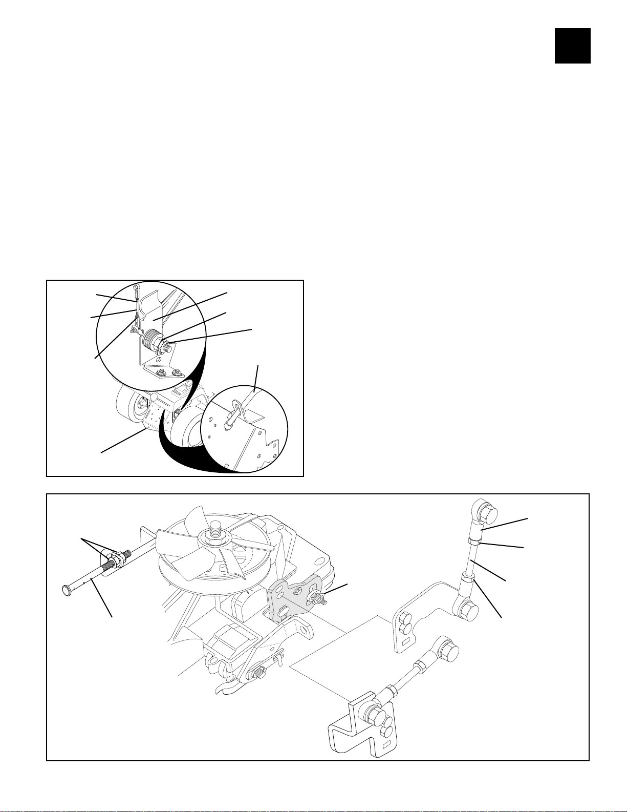
TO ADJUST MOTION CONTROL LEVER
The motion control lever has been preset at the factory and
adjustment should not be necessary.
If for any reason the motion control lever will not hold its
position while at a selected speed, it may be adjusted
at the friction pack located on the right side of transmission.
• Park tractor on level surface. Stop tractor by turning
ignition key to “OFF” position, and engage parking
brake.
LT (See Fig. 2):
•Adjust motion control lever by tightening adjustment locknut one half (1/2) turn.
GT (See Fig. 1):
•Place motion control lever in neutral (N) position.
•While holding locknut, loosen jam nut.
•Tighten locknut 1/4 turn.
•While holding locknut, tighten jam nut securely.
JAM NUT
LINKAGE
CONNECTING ROD
JAM NUT
DRAWBAR
TURNBUCKLE/
LINKAGE
LOCKNUT
JAM NUT
FREEWHEEL
CONTROL ROD
NOTE: If for any reason the effort to move
the motion control lever becomes too excessive, reverse the
above adjustment procedure by loosening locknut 1/
4 to 1/2 turn.
Road test tractor after adjustment and repeat procedure if
necessary.
TO ADJUST NEUTRAL POSITION
The Neutral (N) position of the motion control lever has
been preset at the factory and adjustment should not
be necessary.
If your tractor tends to "creep" when the motion control
lever is in the neutral (N) position, adjust the neutral
lever position as follows.
LT (See Fig. 2):
•Sit on the tractor in the normal operators position.
Start the engine and disengage the parking brake so
that the foot pedal is in the full up position.
•Move the motion control lever until the tractor no
longer moves forward or backwards. Stop the engine
and remove the key.
•Loosen the jam nuts on balljoint shift linkage and
twist connecting rod clockwise or counterclockwise
until motion control lever falls into the neutral slot.
Tighten jam nuts and retest.
GT (See Fig. 1):
•Place motion control lever in neutral position.
•Locate turnbuckle/linkage at top right corner of draw-
bar and loosen jam nuts.
•Place concrete block under drawbar to lift rear wheels
off ground. Start engine and turn linkage connecting
rod clockwise or counterclockwise until the rear tires
stop turning.
•Stop the engine and remove the key. Tighten jam
nuts and retest for creeping with fastest engine rpm
from both forward and reverse.
3
ROD NUTS
(IF EQUIPPED)
FREEWHEEL
CONTROL
ROD
FIG. 1
FIG. 2
29
MODEL 0750
TRANSAXLE
ADJUSTMENT
LOCKNUT
BALLJOINT
SHIFT
LINKAGE
JAM NUT
CONNECTING LINK
JAM NUT
MODEL 0500
TRANSAXLE
www.mymowerparts.com

For Husqvarna Parts Call 606-678-9623 or 606-561-4983
3
NEUTRAL ADJUSTMENT FOR AUTOMATIC DRIVE CONTROL LEVER
1. Place the tractor on a smooth paved level surface.
2. Loosen Adjustment Bolt in front of the right rear wheel, and lightly tighten using a 1/2" wrench.
3. Start Engine and move Lever until tractor does not move forward or backward.
Hold Control Lever in that position and do not move. Turn the engine off.
4. While holding the Control Lever to keep it from moving, loosen theAdjustment Bolt . Move the
Control Lever to the position indicated for Neutral on the fender. Tighten Adjustment Bolt
securely.
FINE TUNE THE NEUTRAL ADJUSTMENT ON AUTOMATIC DRIVE
1. Place the tractor on a smooth paved level surface.
2. Loosen the Adjustment Bolt using a 1/2" wrench. If the tractor is creeping forward, move the
Control Lever forward 1/4 to 1/2 inch. Move the Control Lever rearward 1/4 to 1/2 inch if the
tractor is creeping backwards. Tighten the Adjustment Bolt securely.
3. Start engine and test from both forward and reverse.
4. If tractor still creeps, repeat step # 2 until satisfied.
NOTE: If additional clearance is needed to get to adjustment bolt, move mower deck height to the
lowest position.
NEUTRAL ADJUSTMENT FOR GEAR DRIVE SHIFT LEVER
1. Place the tractor on a level surface.
2. With the engine off and the parking brake disengaged, push the tractor from behind while shifting
gears.When the tractor rear wheels move freely, the transaxle is in neutral. Leave in this position.
3. Loosen Adjustment Bolt in front of the right rear wheel,using a 1/2" wrench. Position the Lever
in the position indicated for Neutral.Tighten Adjustment Bolt securely.
NOTE: If additional clearance is needed to get to adjustment bolt, move mower deck height to the
lowest position.
30
www.mymowerparts.com
 Loading...