

Husqvarna TE250R-310R 2012, TXC250R-310R 2012 Owner's manual

TE 250R - 310R 2013
TE 310R 2013 USA
TXC 250R - 310R 2013 USA
Manuale utente_Owner’s manual_Manuel d’utilisateur_Benutzerhandbuch_Manual del usuario
TE
TXC
TE 250R - 310R 2013
TE 310R 2013 USA
EN
EN
Ed. 06-2012 - Rev. 00
Unless specified, data and prescription are referred to all the models.
TXC 250R - 310R 2013 USA
SPECIFICATIONS - OPERATION - MAINTENANCE
EN - 1

TABLE OF CONTENTS
PRESENTATION
...................................................................... 3
IMPORTANT NOTICES
IDENTIFICATION DATA
CONTROL LOCATION (TE)........................................................6
CONTROL LOCATION (TXC)
TECHNICAL DATA
LUBRICATION TABLE, SUPPLIES
CONTROLS
........................................................................... 10
................................................................................ 28
RIDING
APPENDIX
............................................................................50
PRE-DELIVERY INSPECTION
ALPHABETICAL INDEX
............................................................. 3
............................................................ 5
......................................................7
...................................................................8
............................................... 9
................................................... 51
........................................................... 52
Page
PERIODIC MAINTENANCE -ADJUSTMENT .................. Appendix
•References to the “left” or “right” of the motorcycle are in
Note
the sense of a person facing forwards.
•Z: number of teeth
• A: Austria
AUS: Australia
B: Belgium
BR: Brazil
CDN: Canada
CH: Switzerland
D: Germany
E: Spain
F: France
A
FIN: Finland
GB: Great Britain
I: Italy
J: Japan
USA: United States of America
•Where not specified, all the data and the instructions are
referred to any and all Countries.
SPECIFICATIONS - OPERATION - MAINTENANCE
EN - 2
PRESENTATION
Welcome to the Husqvarna motorcycling Family!
Your new Husqvarna motorcycle is designed and manufactured to be the finest in its field.
The instructions in this book have been prepared to provide
a simple and understandable guide for your motorcycle’s
operation and care.
Follow the instructions carefully to obtain maximum performance and your personal motorcycling pleasure. Your
owner’s manual contains instructions for owner care and
maintenance.
The main work of repair or maintenance requires the attention of a skilled mechanic and the use of special tools
and equipment.
Your Husqvarna dealer has the facilities, experience and original parts necessary to properly render this valuable service.
This “Owner’s Manual” is part and parcel of the motorcycle, hence, this had to
remain with the motorcycle even when
sold to another user.
This motorcycle uses components designed thanks to systems and state of the art technologies which are thereafter
tested in competition.
In competition motorcycles, every detail is verified after each
race in order to always guarantee better performance. For
correct functioning of the vehicle, it is necessary to follow the
maintenance and control table found on Appendix A.
IMPORTANT NOTICES
1) The TXC models are guaranteed COMPETITION motorcycles exempt from functional
defects, the suggested maintenance table for
competition use is shown on Appendix A.
2) TE vehicles are STREET LEGAL motorcycles (with LIMITED POWER ENGINE); they are
guaranteed exempt from functional defects
and covered with legal guarantee, if the
STANDARD CONFIGURATION is maintained
and the suggested maintenance table, shown
on Appendix A is observed.
If TE vehicles are transformed in COMPETITION MOTORCYCLES (with FULL POWER ENGINE), the suggested maintenance table for
competition use is shown on Appendix A.
TXC
TE
MOTOCROSS
EN
ENDURO
SPECIFICATIONS - OPERATION - MAINTENANCE
EN - 3

IMPORTANT
The reference for recognition of the guarantee will be the MOTORCYCLE CONFIGURATION, as shown below:
A) STANDARD MOTORCYCLE, STREET LEGAL: with LIMITED
POWER ENGINE
B) COMPETITION MOTORCYCLE, RACING USE: with FULL POWER
ENGINE
This motorcycles was not designed for long
trips with the engine always at maximum
rpm as can occur whilst travelling on roads
or highways. Long trips at full throttle can
cause severe damage to the engine.
This motorcycles is setup for competition use
and therefore guarantees maximum performance with the rider alone. It is thereby
not recommended to use the vehicle on circuits or off-road with a passenger.
ALWAYS keep in mind that these motorcycles have been designed strictly for competition use, that is, for conditions of
usage very different from those presented on the road.
ALWAYS keep in mind that these motorcycles
have been designed strictly for competition
use, that is, for conditions of usage very different from those presented on the road.
In order to maintain the vehicle’s “Guarantee of Functionality”, the client must follow
the maintenance program indicated in the
user’s manual by carrying out maintenance
checks at authorized HUSQVARNA dealers.
The cost for substituting parts and for the
labour necessary in order to respect the
maintenance plan, is charged to the client.
NOTE: the guarantee is EXTINGUISHED in the
case where the motorcycle is rented.
Important Notice
Read this manual carefully and pay special attention to statements preceeded by the following words:
Warning*: Indicates a possibility of severe
personal injury or loss of life if instructions
are not followed.
Caution*: Indicates a possibility of personal
injury or equipment damage if instructions
are not followed.
Note*: Gives helpful information.
Parts Replacement
When parts replacement is required, use only Husqvarna ORIGINAL parts.
Warning*: After an upset, inspect the motorcycle carefully. Make sure that the throttle,
brake, clutch and all other systems are undamaged. Riding with a damaged motorcycle can lead to a serious crash.
Warning*: Never attempt to start or operate
your motorcycle unless you are wearing appropriate protective clothing. Always wear a
motorcycle helmet, motorcycle boots, gloves,
goggles and other appropriate protective
clothing.
Warning*: This motorcycle is a state of the
art competition bike. Do not attempt to start
or ride this motorcycle until you have received expert instruction and are in excellent
physical condition.
PRECAUTIONS FOR CHILDREN
WARNING
• Park the vehicle where it is unlikely to
be bumped into or damaged. Even slight or
involuntary bumps can cause the vehicle to
topple over, with subsequent risk of serious
harm to people or children.
• To prevent the vehicle from tipping over,
never park it on soft or uneven ground, nor
on asphalt strongly heated by the sun.
•Engine and exhaust pipes become very hot
during riding. Always park your motorcycle where people or children can not easily
reach these parts, in order to avoid serious
burns.
SPECIFICATIONS - OPERATION - MAINTENANCE
EN - 4
IDENTIFICATION DATA
The engine number is printed on the upper side of the engine
case, whereas the frame number is printed on the steering tube.
Always state the number stamped on the frame
(and write it on this booklet), when placing orders for spare
parts, or when asking for informations about your motorcicle.
TE 250
ZKHA300AADV000001
(l) (▲) (♦)
TXC 250 - USA
ZKHTX253#DV000001
EN
(l) (▲) (♦)
FRAME NUMBER
VEHICLE IDENTIFICATION NUMBER (V.I.N.)
The full 17 digit serial, or Vehicle Identification Number, is
stamped on the steering head tube (R.H. side).
(l) = Model designation
(▲) = Model Year (2013)
(♦) = Progressive no.
1. Frame serial number
2. Engine serial number
1
TE 310
ZKHA301AADV000001
TE 310 USA
ZKHKCEDG#DV000001
2
(l) (▲) (♦)
(l) (▲) (♦)
SPECIFICATIONS - OPERATION - MAINTENANCE
TXC 310 - USA
ZKHTX313#DV000001
(l) (▲) (♦)
EN - 5
11
12
13
14
CONTROLS LOCATION (TE)
1. Front brake lever
2. Throttle twistgrip
3. Engine stop button
4. Engine start button
5. L.H. switch
6. Clutch control lever
4
7. Starting device
8. Gear shift pedal
2
1
9. Rear brake control pedal
10. Master cylinder
11. Kick start pedal
12. Fuel tank ller cap
13. Dashboard
14. FI Lamp - Operating failures
8
10
9
SPECIFICATIONS - OPERATION - MAINTENANCE
EN - 6
3
KEYS
Two keys are supplied with the motorcycle (one
of them is a spare key) to be used on steering
lock.
6
7
5
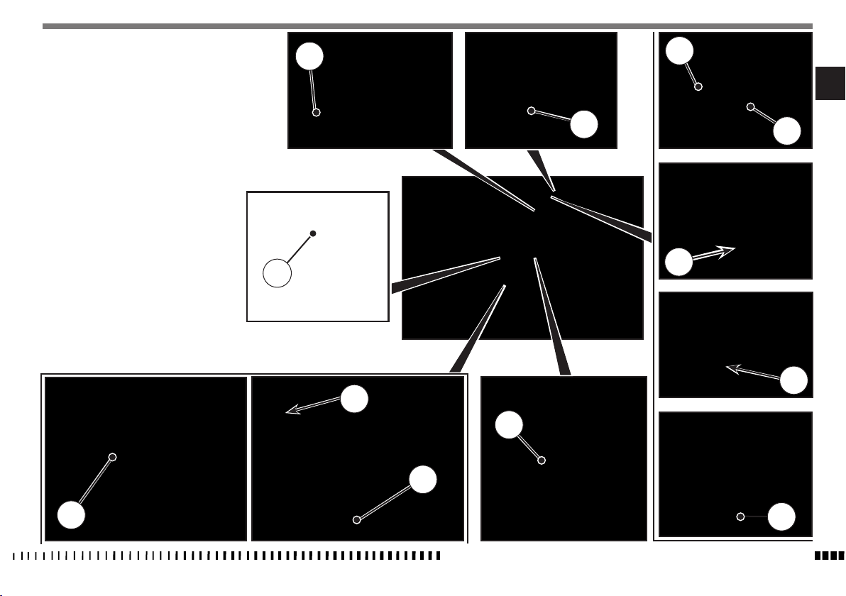
CONTROLS LOCATION (TXC)
1. Front brake lever
2. Throttle twistgrip
3. ENIGINE STOP button (engine stop)
4. Engine start button
5. Clutch control lever
6. Starting device (for cold start)
7. Fuel tank ller cap
8. Control panel
9. Gear shift pedal
10. Rear brake control pedal
11. Master cylinder
12. Kick start pedal
7
8
2
EN
1
12
3
4
11
6
10
9
SPECIFICATIONS - OPERATION - MAINTENANCE
5
EN - 7

TECHNICAL DATA
ENGINE
Type............................................single cylinder, 4 stroke
........................liquid, with electric fan on models
Cooling
TE-TXC 250
Bore ...............................................................3,11 in. (79 mm)
Stroke .....................................................2.00 in. (50,9 mm)
Displacement
Compression ratio
TE-TXC 310
................................15,22 cu. in. (249,5 cm
................................................. 13,6:1
3
Bore ............................................................ 3,23 in. (82 mm)
.......................................................2,26 in. (57,3 mm)
Stroke
Displacement
.............................. 18,46 cu. in. (302,44 cm
Compression ratio
.....................................................13:1
3
Starting................................................................ electric
TIMING SYSTEM
Type...............
4 titanium valves, controlled by twin finger
follower type camshafts, mixed chain/gear drive system
Valve clearance (with engine cold)
.............................................0,006 in. (0,15 mm)
Intake
...........................................0,008 in. (0,20 mm)
Exhaust
LUBRICATION
Type...wet crankcase, lobe pump and cartridge and mesh
filters
IGNITION
Type ...........Electronic, inductive discharge, with
adjustable advance (digital control)
Spark plug type
Spark plug gap
.........................................NGK CR9EIA-9
............... 0.031÷0,035 in. (0,8÷0,9 mm)
FUEL SYSTEM
Type......................................................Electronic injection feed
PRIMARY DRIVE
Drive pinion gear- Clutch ring gear
Transmission ratio
CLUTCH
)
Type...........oil bath multiple disc clutch, hydraulic control
............................................................ 3,176
............................Z 17- Z 54
TRANSMISSION
Type...........................................constant mesh gear type
Transmission ratio
)
............................................... 1,750 (z 28/16)
2nd gear
..............................................1,450 (z 29/26)
3rd gear
...............................................1,227 (z 27/22)
4th gear.
..............................................1,041 (z 25/24)
5 th gear.
...............................................0,884 (z 22/27)
6 th gear
............................................... 2,142 (z 30/14)
1st gear.
SECONDARY DRIVE
Transmission sprocket- Rear wheel sprocket
(TXC)
.........................................................................Z 13- Z 50
(TE)
...........................................................................Z 13- Z 40
Transmission ratio
(TXC)
...............................................................................3,846
(TE).
................................................................................ 3,076
FINAL RATIOS (TE)
1st gear
.....................................20,926
2nd gear
....................................17,096
3rd gear
....................................14,165
4th gear
.....................................11,987
5th gear
.....................................10,169
6th gear
......................................8,636
FINAL RATIOS (TXC)
1st gear
.....................................26,164
2nd gear
....................................21,376
3rd gear
....................................17,251
4th gear
.....................................14,987
5th gear
.....................................12,715
6th gear
.....................................10,797
FRAME
Type...............Steel single tube cradle (roud, rectangular,
ellipsoidal tubes); light alloy rear frame
FRONT SUSPENSION
Type ......”Upside-down” telescopic hydraulic front fork with
advanced axle (adjustable in compression and rebound stroke);
stanchions tubes Ø 1.89 in. (Ø 48 mm)
Legs axis stroke ................................. 11.8 in. (300 mm)
REAR SUSPENSION
Type......progressive with hydraulic single shock absorber
Wheel stroke
..................................... 11.6 in. (296 mm)
FRONT BRAKE
Type ... fixed disc Ø 10.23 in. (Ø 260 mm) “Wave” type with
hydraulic control and floating caliper
REAR BRAKE
Type.... floating disc,
Ø 9.45 in. (Ø 240 mm) “Wave” type
with hydraulic control and floating caliper
RIMS
Front
.......................................................in light alloy: 1,6x21”
Rear......................................................in light alloy: 2,15x18”
SPECIFICATIONS - OPERATION - MAINTENANCE
EN - 8

TIRES
Front . . . .
Rear (TE - TXC). . .
Rear (TE USA). . .
..............................90/90x21”
.......................120/90x18”
........................140/90x18”
Cold tire pressure
...........................0,9÷1,0 Kg/cm
front (*)
front (%) ................................1,1 Kg/cm
rear (*) ............................0,8÷0,9 Kg/cm
rear (%) ................................1,0 Kg/cm
(*) In case of racing use - (%) Road use
DIMENSION, WEIGHT, CAPACITY
Wheelbase ...................... 57.87 in. (1470 mm)
Overall length
...........................88.98 in. (2260 mm)
(TE)
..........................85.67 in. (2176 mm)
(TXC)
Overall width
2
2
Overall height
2
Saddle height
2
Minimum ground clearance
Kerb weight, without fuel
(TE )
250,22 lb. (113,5 kg) (310)
(TXC) .....................239,42 lb. (108,6 kg) (250)
240,52 lb. (109,1 kg) (310)
Fuel tank capacity .......................Imp. Gall. 1.87
U.S. Gall. 2.25
8,5 l
(Qt. reserve included 2.02 Imp. Qt./2.43 U.S. Qt. - 2,3 l)
Coolant capacity ......................0.79 Imp. Quarts
0.95 U.S. Quarts
900 cc
Transmission oil
Oil and oil filter replacement
U.S. Quarts 0.95
900 cc
Oil replacement .......................Imp. Quarts 0.75
U.S. Quarts 0.90
850 cc
.....................32.30 in. (820 mm)
...................50.79 in. (1290 mm)
...................... 37.4 in. (950 mm)
..........11.42 in. (290 mm)
....................... 249,12 lb. (113 kg) (250)
............Imp. Quarts 0.79,
TABLE FOR LUBRICATION, SUPPLIES
Engine, gearbox and primary drive lubricating oil
CASTROL POWER 1 RACING 10W-50
Engine coolant
CASTROL MOTORCYCLE COOLANT
Brake system fluid
CASTROL RESPONSE SUPER DOT 4
Clutch fluid
CASTROL RESPONSE SUPER DOT 4
Grease lubrication
CASTROL PASTE TA GREASE
Final drive chain lubrication
CASTROL CHAIN LUBE RACING
Front fork oil
Kayaba KHL15-11
Oil for rear shock absorber
CASTROL SYNTHETIC FORK OIL 5W
Electric contact protection
CASTROL METAL PARTS CLEANER
CASTROL MOTORCYCLE DWF
Fillers for radiator
AREXONS TURAFALLE LIQUIDO
EN
SPECIFICATIONS - OPERATION - MAINTENANCE
EN - 9
CONTROLS
FUEL COCK
There is an ON-OFF fuel cock (1) on the right side of the
tank; make sure it is always on “ON” position.
There is a screw-type fuel cock (2) on the right side of the
tank; make sure it is always in its max. opening position.
On these models, the cocks operate only as by-passes;
ON-OFF cock has a fuel level sensor which sends the reserve indication to a light on the instrument panel (TE) or
on the control panel (TXC).
WARNING*: Be careful not to touch the hot
engine while operating the fuel valve.
SIDE STAND
These models have a side stand (1) on the left side of the motorcycle.
WARNING*: The stand is designed to support the weight of the MOTORCYCLE ONLY. Do
not sit on the motorcycle using the stand for
support as this could cause structural failure
to the stand and could cause serious bodily
injury.
WARNING*: The motorcycle MUST be set on
the side stand ONLY AFTER the rider has got
off the vehicle. Stand AUTOMATICALLY folds
back to rest position once the vehicle is vertical, no longer resting on the ground.
Periodically check the side stand (see “Periodical maintenance
card”); check that the springs are not damaged and that the
side stand freely moves. If the side stand is noisy, lubricate the
fastening pivot (A).
1
1
2
SPECIFICATIONS - OPERATION - MAINTENANCE
EN - 10
A
FUEL
Recommended fuel: premium grade unleaded fuel. (R.O.N. 96
÷ 98).
WARNING*: Gasoline is extremely flammable and can be explosive under certain conditions. Always stop the engine and do not
smoke or allow flames or sparks in the area
where the motorcycle is refueled or gasoline
is stored.
WARNING*: Do not overfill the tank. After refueling, make sure the tank cap (2) is closed
securely.
COLD START
The motorcycle is equipped with a knob (1) positioned on throttle body for cold start. Pull the knob towards the outside to activate the starter, and on the opposite direction to deactivate it.
1
EN
2
SPECIFICATIONS - OPERATION - MAINTENANCE
EN - 11
DIGITAL INSTRUMENT, WARNING LIGHTS (TE)
- The instrument functions are the following, as shown below.
1- SPEED (Km/h or mph) / ODO
The motorcycle is equipped with a digital instrument; on
the instrument are located 3 warning lights too: high beam,
blinkers and fuel reserve.
1- BLUE warning light “HIGH BEAM”
2- GREEN warning light “BLINKERS”
3- ORANGE warning light “Fuel reserve”
The dashboard is activated only after the engine has been
started.
NOTES
- Every time the engine is started, the dashboard shows the SW
version for the first 2 seconds; after the check routine, the
dashboard shows the last planned function.
- A few seconds after the engine has been turned off, the dashboard is deactivated.
- To select the instrument functions and to set to zero the
functions, use the SCROLL knob (A).
2
1
3
1- SPEED / ODO
2- SPEED / CLOCK
3- SPEED / TRIP
4- SPEED / CHRONO
5- SPEED /
HOUR COUNTER (H)
1- SPEED / ODO
.................
- SPEED: motorcycle speed- maximum value: 299 Km/h or 299
mph;
- ODO: odometer- maximum value: 99999 km;
To go from Km to Miles or from Miles to Km, visit the nearest
Husqvarna dealer.
A
A
SPECIFICATIONS - OPERATION - MAINTENANCE
EN - 12
2- SPEED / CLOCK
- SPEED:
motorcycle speedmaximum value
mph;
- CLOCK:
clock- Reading from 0:00 to 23:59:59;
To reset the clock, push the knob SCROLL (A) for more than 3
seconds in order to increase the hours; release the knob and
then, after 3 seconds, it is possible to increase the minutes;
: 299 Km/h o 299
A
3- SPEED / TRIP
- SPEED:
motorcycle speedmaximum value
- TRP:
distance- maximum value: 999.9 km (the data will be lost
after battery detachment).
To reset TRIP, push the SCROLL button (A) and hold for more
than 3 seconds.
: 299 Km/h o 299 mph
A
4- SPEED / CHRONO
- SPEED:
motorcycle speedmaximum value
mph;
-
LPT: miles/kilometers covered time;
-
Reading from 0:00 to 99:59:59 (the data will be lost after
battery detachment).
To activate the function LPT, push the knob SCROLL (A) for more
than 3 seconds.
- 1st step: function ON;
- 2nd step: stop to the counters;
- 3rd step: LPT reset;
- 4th step: function ON;
- 5th step: stop to the counters;
.............................
and so following
(LPT)
: 299 Km/h o 299
A
5- SPEED /
- SPEED:
mph;
- H: it indicates engine operating hours and minutes.
- Data will be lost after disconnecting the battery.
- To activate the function hour counter (H), push the SCROLL
button (A) and hold for more than 3 seconds.
HOUR COUNTER (H)
motorcycle speedmaximum value
: 299 Km/h o 299
A
EN
SPECIFICATIONS - OPERATION - MAINTENANCE
EN - 13
FI LAMP - OPERATING FAILURES (TE)
FI Lamp (1) is located on the side of the digital dashboard.
WARNING LIGHTS PANEL (TXC)
The motorcycle is tted with a small warning lights panel
with two warning lights:
1 - Red “FI LAMP” warning light (operating failures)
2 - Yellow warning light “FUEL RESERVE”
NOTE: FI LAMP - OPERATING FAILURES (TE - TXC)
IN THE EVENT OF ENGINE AND/OR INJECTION
SYSTEM MALFUNCTION, THE WARNING LIGHT
WILL START BLINKING, THUS COMMUNICATING
A FAILURE.
IF THE WARNING LIGHT TURNS ON, PAY ATTENTION NOT TO RUN THE ENGINE AT FULL THROTTLE AND CONTACT THE NEAREST HUSQVARNA
DEALER.
1
SPECIFICATIONS - OPERATION - MAINTENANCE
EN - 14
TE
TXC
1
2
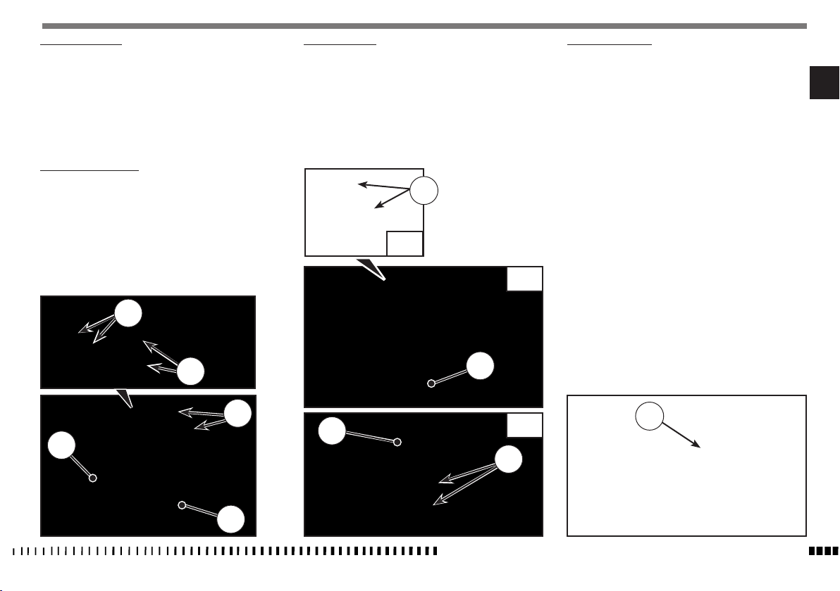
THROTTLE CONTROL
The throttle knob (1), is located on the right hand side of the
handlebar. The position of the throttle control can be adjusted
by loosening the two fastenig screws (A).
CAUTION
Do not forget to tighten the screws (A) after
the adjustment.
FRONT BRAKE CONTROL
The brake control lever (2) is located on the right hand side of
the handlebar. The position of the throttle control can be adjusted by loosening the two fastenig screws (B).
CLUTCH CONTROL
The hydraulic clutch control lever (3) is located on the left-hand
side of the handlebar and is protected against dirt with a rubber guard.
The position of the clutch control on handlebar can be adjusted
by loosening the retaining screws (C).
CAUTION
Do not forget to tighten the screws after the
adjustment.
C
STEERING LOCK (TE)
The motorcycle is equipped with a steering lock (1) on the R.H.
side of the steering head tube.
To lock it, procede as follows:
turn the handlebar leftwards, place the key in lock and turn
counterclockwise. Push the key inwards (if necessary, turn to
and from). Turn the key clockwise and remove it from the lock.
To unlock the steering lock, reverse the above procedure.
EN
CAUTION
Do not forget to tighten the screws (B) after
the adjustment.
B
A
B
1
2
TXC
TXC
3
3
TE
1
C
SPECIFICATIONS - OPERATION - MAINTENANCE
EN - 15
ENGINE START BUTTON
The engine start button (1) is located on the handlebar righthand side.
A
B
1
L.H. HANDLEBAR COMMUTATOR (TE)
Controls:
- Headlamp (A)
1) Selection control High beam
Selection control Low beam
- Turn signals (B), (C)
2) Left turn signals (automatic return)
Right turn signals (automatic return)
To deactivate the turn signals, press the control lever after its
returning to center.
3)
Warning horn
4) Engine stop button.
EN - 16
.
SPECIFICATIONS - OPERATION - MAINTENANCE
4
3
1
C
2
REAR BRAKE CONTROL
The rear brake control (1) is placed on the right-hand side of
the motorcycle.
GEAR SHIFT CONTROL
The lever (1) is placed on the left-hand side of the engine. The
operator must release the lever after each gear change to allow
it to return to its central position before another gear
change can be made.
Neutral position (N) is between first (low) and second gears.
First gear is engaged by pushing the lever downwards; all the
other gears are engaged, by pushing the lever upwards.
The position of the gear shift lever on the shaft can be varied by:
- loosening screw;
- pulling lever out;
- placing lever in new position on the shaft when the operation
is over tighten the screw and then tightening the screw.
CAUTION*: Do not shift gears without disengaging the clutch and closing the throttle. The
engine could be damaged by overspeed and
shock.
N: Neutral
6
5
4
3
2
WARNING*: Do not downshift when traveling
at a speed that would force the engine to
overrev in the next lower gear, or cause the
rear wheel to lose traction.
EN
N
1
1
1
SPECIFICATIONS - OPERATION - MAINTENANCE
EN - 17

RIDING
BEFORE EVERY RIDE MAKE FOLLOWING CHECKS
WARNING!
Before each ride, to prevent accidents or failures during ride,
make sure to go through following list.
1. Check all fluids
A. Engine-transmission oil level
B. fuel level
C. coolant level
Make sure all caps are properly adjusted.
WARNING*: Don’t remove radiator cap when
hot!
Check all controls
2.
A. Throttle handgrip
B. Clutch lever
Make sure cables are not damaged and turn smoothly.
3. Check brakes
Look for brake fluid leaks and worn hoses. Check for proper
functioning.
Check suspensions
4.
Compress fork and rear suspensions. Look for oil leaks and
ensure proper functioning.
Check wheels
5.
Check spokes and look for worn bearings.
Check rims and tyres.
Check tyre pressure.
6. Check chain rollers and sprockets
Check wear on chain rollers and sprockets
Ensure chain is correctly adjusted and lubricated.
7. Check air filter and intake system
Check that air filter is clean
Check all rubber connections and clamps.
8. Check exhaust system
Check hook up, look for cracks
Check muffler.
9. Check torque
A. Spark plug
B. General check of torque
10. Check steering action
Check bearing play.
11. Check the electric system (TE).
Start the engine and check that the front and rear lamps, the
stop light, the turn signals the cluster warning lights and the
horn are working correctly.
WARNING*: Failure to perform these checks
every day before you ride may result in serous damage or a severe accident.
.
RUNNING IN
Before using the motorcycle for sporting activities run in the
engine for two hours at least to increase the life and the performance of the engine.
During the first half-hour of driving we advise keeping a low
speed and avoiding sudden accelerations. Never open the throttle fully.
Change the oil and carry out all the necessary maintenance operations. After the first half-hour of driving, lightly increase the
rev number, but never run the engine at full throttle. Never keep
low speeds when the high gears are inserted.
Slowly drive the motorcycle for two hours before using it for
sporting activities.
CHECKS DURING RUNNING
- SPOKE TENSION OF WHEELS;
- TIGHTENING OF WHEELS;
- FORK PIN TIGHTENING;
- CHAIN ADJUSTMENT;
- STEERING BEARING PLAY;
- HANDLEBAR TIGHTENING;
- ENGINE GRIP TO FRAME;
- SUCTION FITTING GRIP;
- HEAD AND CYLINDER NUTS GRIP;
OFTEN CHECK THE BATTERY CHARGE CONDITION
SPECIFICATIONS - OPERATION - MAINTENANCE
EN - 18
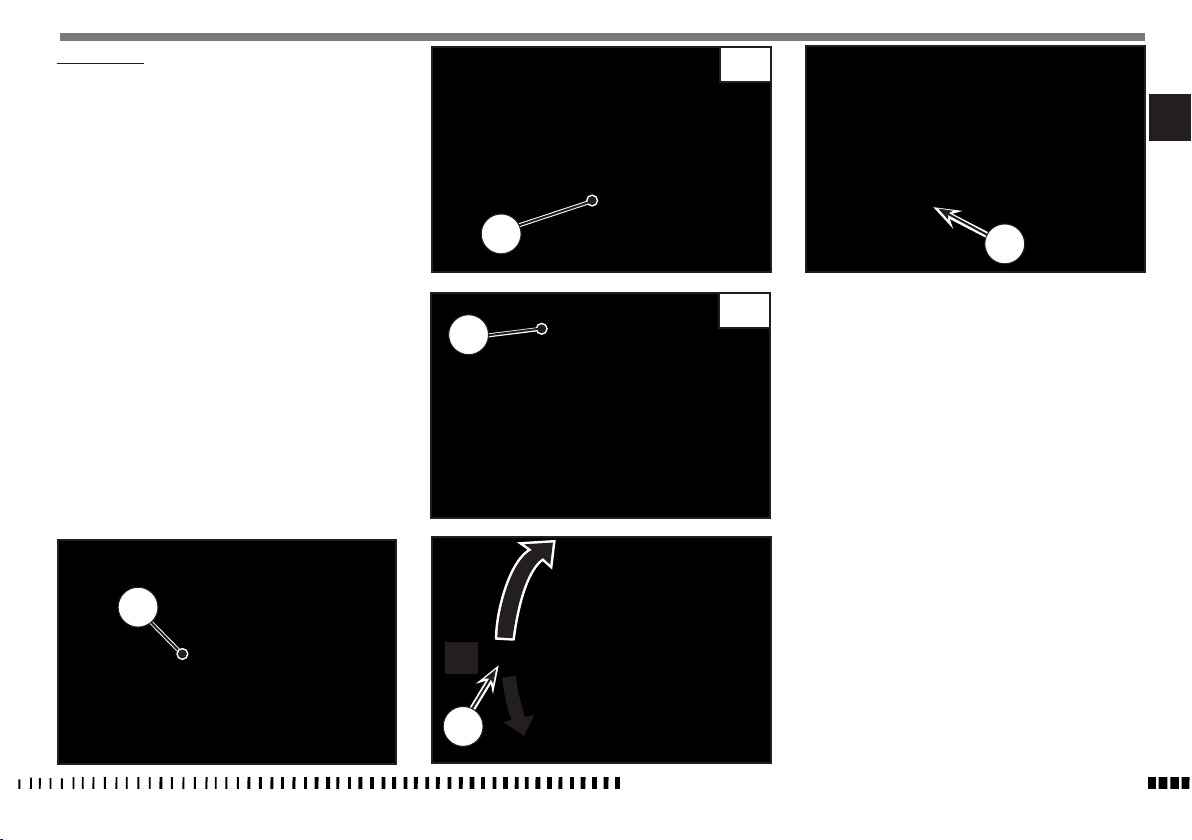
ENGINE START
With cold engine, as after a prolonged inactivity of the
motorcycle or in presence of a low external temperature,
proceed as follows:
1) pull knob (1) towards the outside;
2) pull clutch lever (2) and hold it in place;
3) shift gear pedal (3) to neutral position;
4) press start button (4);
5) release the clutch lever (2);
6) take starter knob (1) back to its initial position as soon as
engine stays idle.
When a cold engine has just been started, do not increase
revs, to ensure an adequate oil warm-up and circulation.
IMPORTANT
NEVER START WITH DISCONNECTED BATTERY.
IMPORTANT
DO NOT OPERATE THE THROTTLE CONTROL WHILE
STARTING-UP.
TXC
EN
2
4
TE
2
IMPORTANT NOTE IN CASE OF COLD STARTS AT
LOW TEMPERATURES
It is recommended to briefly warm-up the engine at idle until,
after having disengaged the starter, there is a normal response
from the engine when opening the throttle.
In this way the oil can reach all the surfaces needing lubrication
and the coolant will reach the necessary temperature for correct
engine function.Avoid overheating the engine.
6
5
1
4
3
2
N
1
Never accelerate the engine after a cold start.
WARNING*: Exhaust contains poisonous carbon monoxide gas. Never run the engine in a
closed garage or in a confined area.
IMPORTANT
3
SPECIFICATIONS - OPERATION - MAINTENANCE
EN - 19
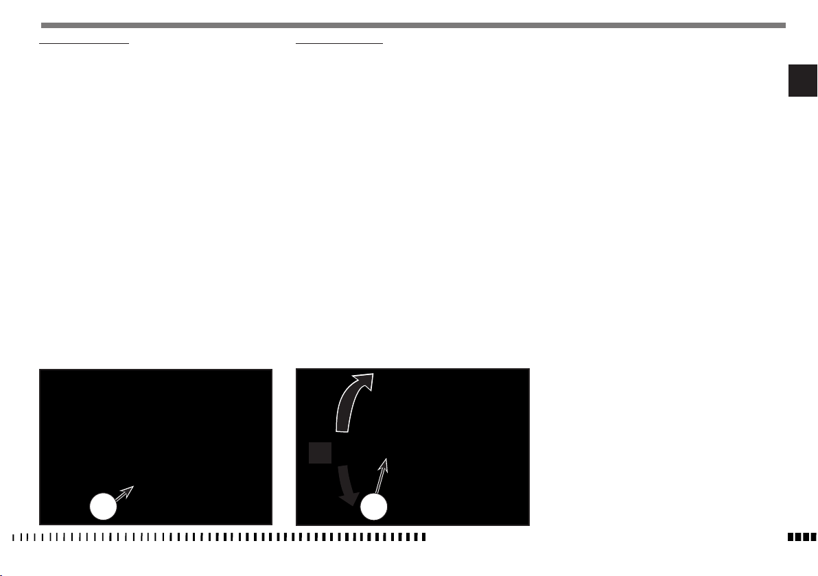
STOPPING THE MOTORCYCLE AND THE ENGINE
- Close the throttle (1) completely so that the engine will help slow
down the motorcycle.
- For normal braking, gradually apply both front and rear brakes
while down shifting (for maximum deceleration, apply the front
and rear brakes firmly).
- Before the motorcycle stops, pull the clutch lever and shift gear
lever (2) into neutral position.
1
- Press the engine stop button (3).
3
TXC
WARNING*: Independent use of the front or
rear brake may be advantageous under certain conditions. Use caution when using the
front brake, especially on slippery surfaces.
Improper use of the brakes can lead to a serious crash.
WARNING*:
or other malfunction that causes the engine to run uncontrollably, pull the clutch
lever IMMEDIATELY and press the engine
stop switch.
mal use of the brakes and steering while
holding the engine stop button down.
In the event of a stuck throttle
Control the motorcycle by nor-
2
SPECIFICATIONS - OPERATION - MAINTENANCE
EN - 20
3
TE
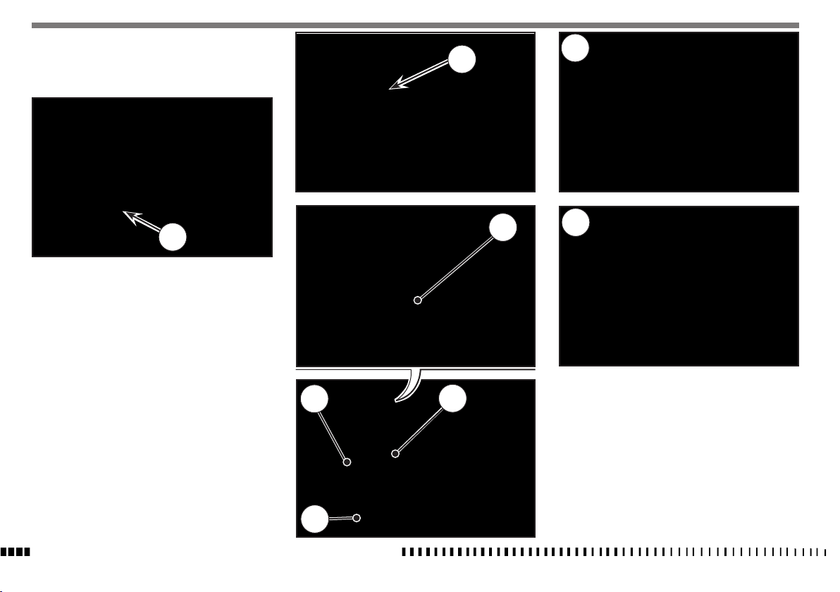
CHECKING THE OIL LEVEL
Keeping the motorbike level and in a vertical position, check the
oil level through the inspection (1) window on the right crankcase.
Make sure the level is in between the MIN and MAX notches.
To fill up, remove the filler cap (2).
Note*: Have this operation made with
warmed-up engine.
WARNING*: Be careful not to touch hot engine oil.
1
a
ENGINE OIL REPLACEMENT AND BAG FILTERS-FILTER
CARTRIDGE CLEANING OR REPLACEMENT
WARNING*: Be careful not to touch hot engine oil.
Drain the oil with WARM ENGINE; proceed as follows:
• remove oil filler cap (2);
• remove the engine lower guard (A);
• place an oil drain pan under the engine block;
TE - TXC 250
• Remove the oil drain cap (3), the mesh filter (4) and drain
the old oil;
TE - TXC 310
• loosen tie (3a) without disconnecting tube (3b);
• unscrew hose tail (3c), remove mesh filter (4) and drain the
used oil.
• Clean the mesh filter with benzine;
• in order to replace the filter cartridge (5), unscrew the three
fastening screws then the filter cartridge cover (6).
Once the oil filters have been cleaned-replaced, fit the parts
back in, in the opposite sequence to the disassembly, and pour
in the prescribed amount of oil, as listed in the LUBRICATION
TABLE.
5
EN
A
3
4
250
6
3c
310
3a
2
4
SPECIFICATIONS - OPERATION - MAINTENANCE
3b
EN - 21
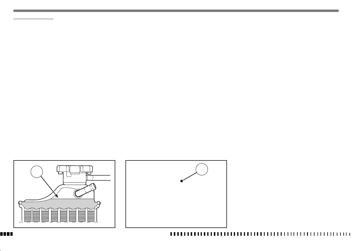
COOLANT LEVEL CHECK
Check level (1) in right-hand radiator when engine is cold (place
the motorcycle so that it is perpendicular to the ground). The
coolant should be approximately 10 mm above cells and besides.
The radiator cap (A) is provided of two unlocking positions, the
first being for the previous pressure discharge in the cooling
system.
WARNING
Avoid removing radiator cap when engine
is hot, as coolant may spout out and cause
scalding.
NOTE
Difficulties may arise in eliminating coolant
from varnished surfaces. If this occurs, wash
off with water.
1
SPECIFICATIONS - OPERATION - MAINTENANCE
EN - 22
A
REPLACEMENT OF COOLING FLUID
Place a vessel on the L.H. side of the cylinder, under the Piping (1).
Remove the exhaust pipe (a). Loosen the pipe strap (2) of the piping (1), take the pipe off the fitting that secures it to the engine, then
SLOWLY open the R.H. radiator cap (3); slope the motorcycle on the left
side to drain the coolant easily in the vessel.
When finished, refit the hose (1), secure it with the clamp (2)
and refit the drain hose.
Pour the necessary quantity of coolant in the radiator then warm
up the engine in order to eliminate any possible air bubbles.
Periodically check the connecting hoses (see “Periodical maintenance card”): this will avoid coolant leakages and consequent
engine seizure: If hoses (A) show cracks, swelling or hardenings
due to sheats desiccation, their replacement shall be advisable.
Check the correct tightening of the clamps (B).
A: Piping
B: Clamps
EN
B
A
B
a
A
3
1
2
SPECIFICATIONS - OPERATION - MAINTENANCE
A
B
EN - 23
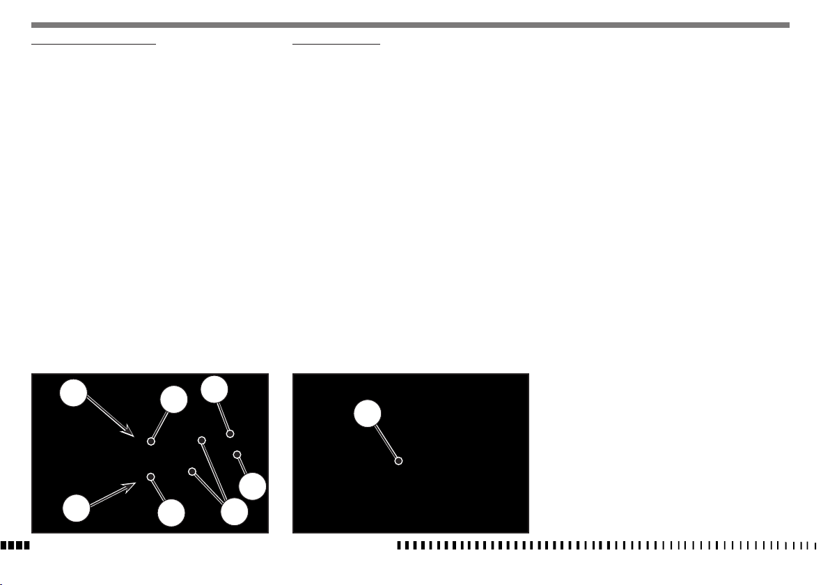
THROTTLE CABLE ADJUSTMENT
To check the correct adjustment of the throttle operate as follows:
- Remove rubber caps (1);
- by moving the opening cable (2) back and forth, check that
free play is 3 mm;
- by moving the closing cable (3) back and forth, check that free
play is 1 mm;
- if it does not happen, loosen the nut (4) and appropriately
turn the adjuster screw (5);
(loosen it to decrease clearance, tighten it to increase it);
- after adjustment block the nut (4).
WARNING*: Operation with damaged throttle cable could result in an unsafe riding condition.
WARNING*: Exhaust gas contains poisonous
carbon monoxide gas. Never run the engine
in a closed area or in a confined area.
ADJUSTING THE IDLE
Adjust the carburetor with warm engine and with the throttle
control in closed position. Proceed as follows:
- turn the knob (1) on the left side of the throttle body of about
34 clicks from the fully closed position, checking with the suitable device that revs are of about 1,950 RPM (turn clockwise
to increase the speed and counter clockwise to reduce it).
4
2
5
3
4
SPECIFICATIONS - OPERATION - MAINTENANCE
EN - 24
5
1
1
 Loading...